Embed Size (px)
Citation preview
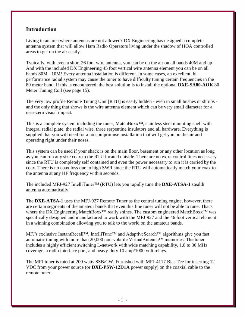
Auto Tuned Multi-Band HF
Stealth Antenna System DXE-ATSA-1
DXE-ATSA-1-INS Revision 0b
DXE-ATSA-1 shown with optional DXE-SA80-AOK
© DX Engineering 2012
P.O. Box 1491 ∙ Akron, OH 44309-1491 USA
Phone: (800) 777-0703 ∙ Tech Support and International: (330) 572-3200
Fax: (330) 572-3279 ∙ E-mail: [email protected]
- 1 -
Introduction
Living in an area where antennas are not allowed? DX Engineering has designed a complete
antenna system that will allow Ham Radio Operators living under the shadow of HOA controlled
areas to get on the air easily.
Typically, with even a short 26 foot wire antenna, you can be on the air on all bands 40M and up –
And with the included DX Engineering 45 foot vertical wire antenna element you can be on all
bands 80M - 10M! Every antenna installation is different. In some cases, an excellent, hi-
performance radial system may cause the tuner to have difficulty tuning certain frequencies in the
80 meter band. If this is encountered, the best solution is to install the optional DXE-SA80-AOK 80
Meter Tuning Coil (see page 15).
The very low profile Remote Tuning Unit [RTU] is easily hidden - even in small bushes or shrubs -
and the only thing that shows is the wire antenna element which can be very small diameter for a
near-zero visual impact.
This is a complete system including the tuner, MatchBoxx™, stainless steel mounting shelf with
integral radial plate, the radial wire, three serpentine insulators and all hardware. Everything is
supplied that you will need for a no compromise installation that will get you on the air and
operating right under their noses.
This system can be used if your shack is on the main floor, basement or any other location as long
as you can run any size coax to the RTU located outside. There are no extra control lines necessary
since the RTU is completely self contained and even the power necessary to run it is carried by the
coax. There is no coax loss due to high SWR since the RTU will automatically match your coax to
the antenna at any HF frequency within seconds.
The included MFJ-927 IntelliTuner™ (RTU) lets you rapidly tune the DXE-ATSA-1 stealth
antenna automatically.
The DXE-ATSA-1 uses the MFJ-927 Remote Tuner as the central tuning engine, however, there
are certain segments of the amateur bands that even this fine tuner will not be able to tune. That's
where the DX Engineering MatchBoxx™ really shines. The custom engineered MatchBoxx™ was
specifically designed and manufactured to work with the MFJ-927 and the 46 foot vertical element
in a winning combination allowing you to talk to the world on the amateur bands.
MFJ's exclusive InstantRecall™, IntelliTune™ and AdaptiveSearch™ algorithms give you fast
automatic tuning with more than 20,000 non-volatile VirtualAntenna™ memories. The tuner
includes a highly efficient switching L-network with wide matching capability, 1.8 to 30 MHz
coverage, a radio interface port, and heavy-duty 10 amp/1000 volt relays.
The MFJ tuner is rated at 200 watts SSB/CW. Furnished with MFJ-4117 Bias Tee for inserting 12
VDC from your power source (or DXE-PSW-12D1A power supply) on the coaxial cable to the
remote tuner.
- 2 -
Tools Required
Nut Drivers 1/4, 5/16, 3/8, 7/16
Open End Wrenches 5/16, 3/8, 7/16
Wire Cutter
Wire Stripper
Terminal Crimper
Optional (for radial wires) Soldering Iron and Solder
Please read and understand the instruction manual that comes with the MFJ-927 Remote
IntelliTuner™ Automatic Antenna Tuner.
There is information included in that manual that is critical to proper operation of both the
IntelliTuner™ Automatic Antenna Tuner and the Bias "T".
There is also troubleshooting information and tuner reset information that may be very
helpful.
Manual Updates
Every effort is made to supply the latest manual revision with each product. Occasionally a manual
will be updated between the time your DX Engineering product is shipped and when you receive it.
Please check the DX Engineering web site (www.DXEngineering.com) for the latest revision
manual.
Assembly Steps
The DXE-ATSA-1 Auto Tuned Multi-Band HF Stealth Antenna System is assembled in the
following steps:
Installing Ground Spikes and Antenna Insulator on Shelf
MatchBoxx™ installed on Shelf
MFJ-927 Tuner installed on Shelf
Connecting Ground Wire and Tuner Wires to Shelf and MatchBoxx™
Site Selection
Coaxial Cable Installation
Radial System and Attaching Ground Radial Wires to Shelf
Wire Antenna Element to MatchBoxx™
Attaching Wire Antenna Element to the End Insulators
Attaching Support Rope to the End Insulators
Bias "T" connections
Using the MFJ-927 Auto-Tuner
- 3 -
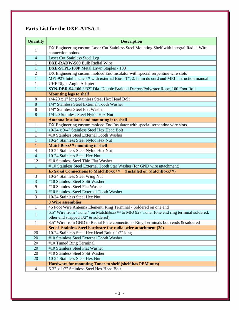
Parts List for the DXE-ATSA-1
Quantity Description
1 DX Engineering custom Laser Cut Stainless Steel Mounting Shelf with integral Radial Wire
connection points
4 Laser Cut Stainless Steel Leg
1 DXE-RADW-500 Bulk Radial Wire
1 DXE-STPL-100P Metal Lawn Staples - 100
2 DX Engineering custom molded End Insulator with special serpentine wire slots
1 MFJ-927 IntelliTuner™ with external Bias "T", 2.1 mm dc cord and MFJ instruction manual
1 UHF Right Angle Adapter
1 SYN-DBR-94-100 3/32" Dia. Double Braided Dacron/Polyester Rope, 100 Foot Roll
Mounting legs to shelf
8 1/4-20 x 1" long Stainless Steel Hex Head Bolt
8 1/4" Stainless Steel External Tooth Washer
8 1/4" Stainless Steel Flat Washer
8 1/4-20 Stainless Steel Nyloc Hex Nut
Antenna Insulator and mounting it to shelf
1 DX Engineering custom molded End Insulator with special serpentine wire slots
1 10-24 x 3/4" Stainless Steel Hex Head Bolt
1 #10 Stainless Steel External Tooth Washer
1 10-24 Stainless Steel Nyloc Hex Nut
1 MatchBoxx™ mounting to shelf
4 10-24 Stainless Steel Nyloc Hex Nut
4 10-24 Stainless Steel Hex Nut
12 #10 Stainless Steel Thin Flat Washer
1 # 10 Stainless Steel External Tooth Star Washer (for GND wire attachment)
External Connections to MatchBoxx ™ (Installed on MatchBoxx™)
3 10-24 Stainless Steel Wing Nut
3 #10 Stainless Steel Split Washer
9 #10 Stainless Steel Flat Washer
3 #10 Stainless Steel External Tooth Washer
3 10-24 Stainless Steel Hex Nut
3 Wire assemblies
1 45 Foot Wire Antenna Element, Ring Terminal - Soldered on one end
1 6.5" Wire from "Tuner" on MatchBoxx™ to MFJ 927 Tuner (one end ring terminal soldered,
other end stripped 1/2" & soldered)
1 3.5" Wire from GND to Radial Plate connection - Ring Terminals both ends & soldered
Set of Stainless Steel hardware for radial wire attachment (20)
20 10-24 Stainless Steel Hex Head Bolt x 1/2" long
20 #10 Stainless Steel External Tooth Washer
20 #10 Tinned Ring Terminal
20 #10 Stainless Steel Flat Washer
20 #10 Stainless Steel Split Washer
20 10-24 Stainless Steel Hex Nut
Hardware for mounting Tuner to shelf (shelf has PEM nuts)
4 6-32 x 1/2" Stainless Steel Hex Head Bolt
- 4 -
Recommended Optional Items
Quantity Description
1 DXE-PSW-12D1A AC Adapter 12 VDC/1000 ma
1 UMI-81343 Anti-Seize, 1 oz Squeeze Tube
1 SUM-900031 Automatic Wire Stripper/Crimper/Cutter, 24-10 Ga.
1 DXE-3M2155 3M Temflex™ 2155 Rubber Splicing Tape
1 TRM-06133 Scotch Super 33+ Vinyl Electrical Tape
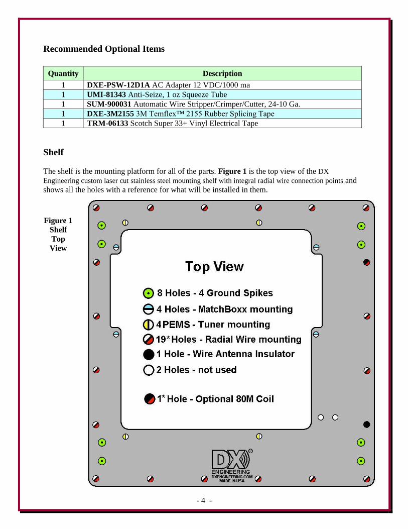
Shelf
The shelf is the mounting platform for all of the parts. Figure 1 is the top view of the DX
Engineering custom laser cut stainless steel mounting shelf with integral radial wire connection points and
shows all the holes with a reference for what will be installed in them.
Figure 1
Shelf
Top
View
- 5 -
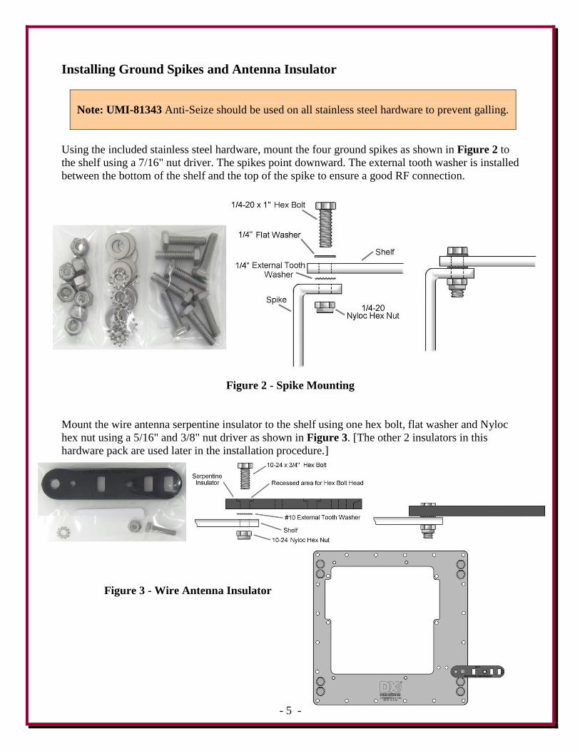
Installing Ground Spikes and Antenna Insulator
Note: UMI-81343 Anti-Seize should be used on all stainless steel hardware to prevent galling.
Using the included stainless steel hardware, mount the four ground spikes as shown in Figure 2 to
the shelf using a 7/16" nut driver. The spikes point downward. The external tooth washer is installed
between the bottom of the shelf and the top of the spike to ensure a good RF connection.
Figure 2 - Spike Mounting
Mount the wire antenna serpentine insulator to the shelf using one hex bolt, flat washer and Nyloc
hex nut using a 5/16" and 3/8" nut driver as shown in Figure 3. [The other 2 insulators in this
hardware pack are used later in the installation procedure.]
Figure 3 - Wire Antenna Insulator
- 6 -
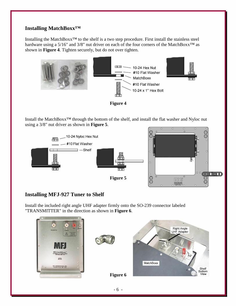
Installing MatchBoxx™
Installing the MatchBoxx™ to the shelf is a two step procedure. First install the stainless steel
hardware using a 5/16" and 3/8" nut driver on each of the four corners of the MatchBoxx™ as
shown in Figure 4. Tighten securely, but do not over tighten.
Figure 4
Install the MatchBoxx™ through the bottom of the shelf, and install the flat washer and Nyloc nut
using a 3/8" nut driver as shown in Figure 5.
Figure 5
Installing MFJ-927 Tuner to Shelf
Install the included right angle UHF adapter firmly onto the SO-239 connector labeled
"TRANSMITTER" in the direction as shown in Figure 6.
Figure 6
- 7 -
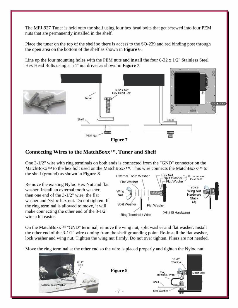
The MFJ-927 Tuner is held onto the shelf using four hex head bolts that get screwed into four PEM
nuts that are permanently installed in the shelf.
Place the tuner on the top of the shelf so there is access to the SO-239 and red binding post through
the open area on the bottom of the shelf as shown in Figure 6.
Line up the four mounting holes with the PEM nuts and install the four 6-32 x 1/2" Stainless Steel
Hex Head Bolts using a 1/4" nut driver as shown in Figure 7.
Figure 7
Connecting Wires to the MatchBoxx™, Tuner and Shelf
One 3-1/2" wire with ring terminals on both ends is connected from the "GND" connector on the
MatchBoxx™ to the hex bolt used on the MatchBoxx™. This wire connects the MatchBoxx™ to
the shelf (ground) as shown in Figure 8.
Remove the existing Nyloc Hex Nut and flat
washer. Install an external tooth washer,
then one end of the 3-1/2" wire, the flat
washer and Nyloc hex nut. Do not tighten. If
the ring terminal is allowed to move, it will
make connecting the other end of the 3-1/2"
wire a bit easier.
On the MatchBoxx™ "GND" terminal, remove the wing nut, split washer and flat washer. Install
the other end of the 3-1/2" wire coming from the shelf grounding point. Re-install the flat washer,
lock washer and wing nut. Tighten the wing nut firmly. Do not over tighten. Pliers are not needed.
Move the ring terminal at the other end so the wire is placed properly and tighten the Nyloc nut.
Figure 8
- 8 -
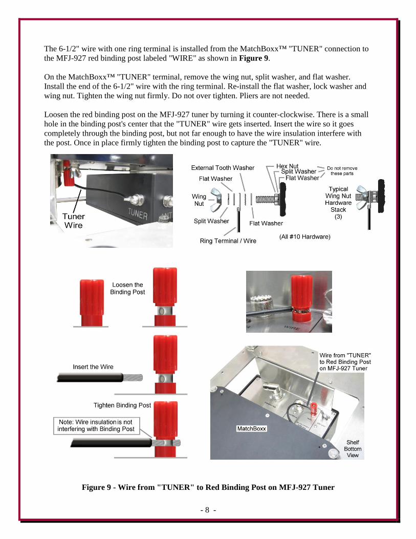
The 6-1/2" wire with one ring terminal is installed from the MatchBoxx™ "TUNER" connection to
the MFJ-927 red binding post labeled "WIRE" as shown in Figure 9.
On the MatchBoxx™ "TUNER" terminal, remove the wing nut, split washer, and flat washer.
Install the end of the 6-1/2" wire with the ring terminal. Re-install the flat washer, lock washer and
wing nut. Tighten the wing nut firmly. Do not over tighten. Pliers are not needed.
Loosen the red binding post on the MFJ-927 tuner by turning it counter-clockwise. There is a small
hole in the binding post's center that the "TUNER" wire gets inserted. Insert the wire so it goes
completely through the binding post, but not far enough to have the wire insulation interfere with
the post. Once in place firmly tighten the binding post to capture the "TUNER" wire.
Figure 9 - Wire from "TUNER" to Red Binding Post on MFJ-927 Tuner
- 9 -
Site Selection
Select a mounting location for the DXE-ATSA-1 clear from power lines, structures and other
antennas. Consider overhead power lines, utility cables and wires.
The vertical wire element should be mounted away from local noise sources or other metallic
objects which can re-radiate noise and affect the tuning, radiation pattern and SWR.
Adequate space should be available for the radial wires which will extend out from the DXE-
ATSA-1 in a 25 foot radius.
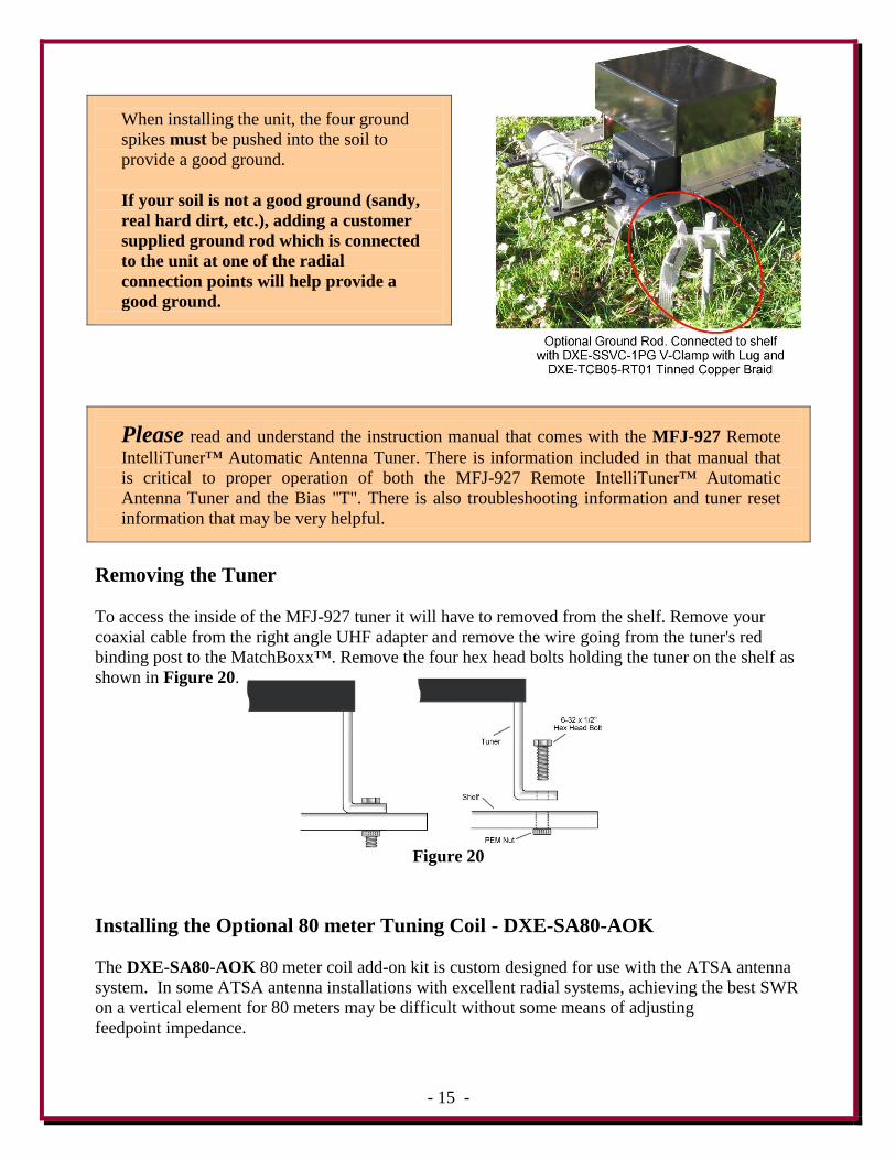
When installing the unit, the four ground spikes must be pushed into the
soil to provide a good RF ground.
If your soil is not a good RF ground (sandy, real hard dirt, etc.),
adding a customer supplied ground rod which is installed near the
DXE-ATSA-1 and connected to the DXE-ATSA-1 at one of the radial
wire connection points will help provide a good RF ground.
Refer to Figure 17 for examples of installation sites.
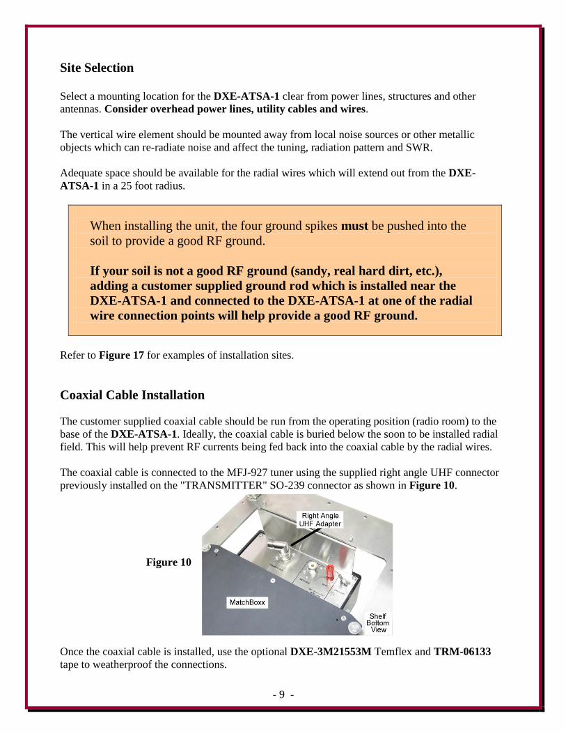
Coaxial Cable Installation
The customer supplied coaxial cable should be run from the operating position (radio room) to the
base of the DXE-ATSA-1. Ideally, the coaxial cable is buried below the soon to be installed radial
field. This will help prevent RF currents being fed back into the coaxial cable by the radial wires.
The coaxial cable is connected to the MFJ-927 tuner using the supplied right angle UHF connector
previously installed on the "TRANSMITTER" SO-239 connector as shown in Figure 10.
Figure 10
Once the coaxial cable is installed, use the optional DXE-3M21553M Temflex and TRM-06133
tape to weatherproof the connections.
- 10 -
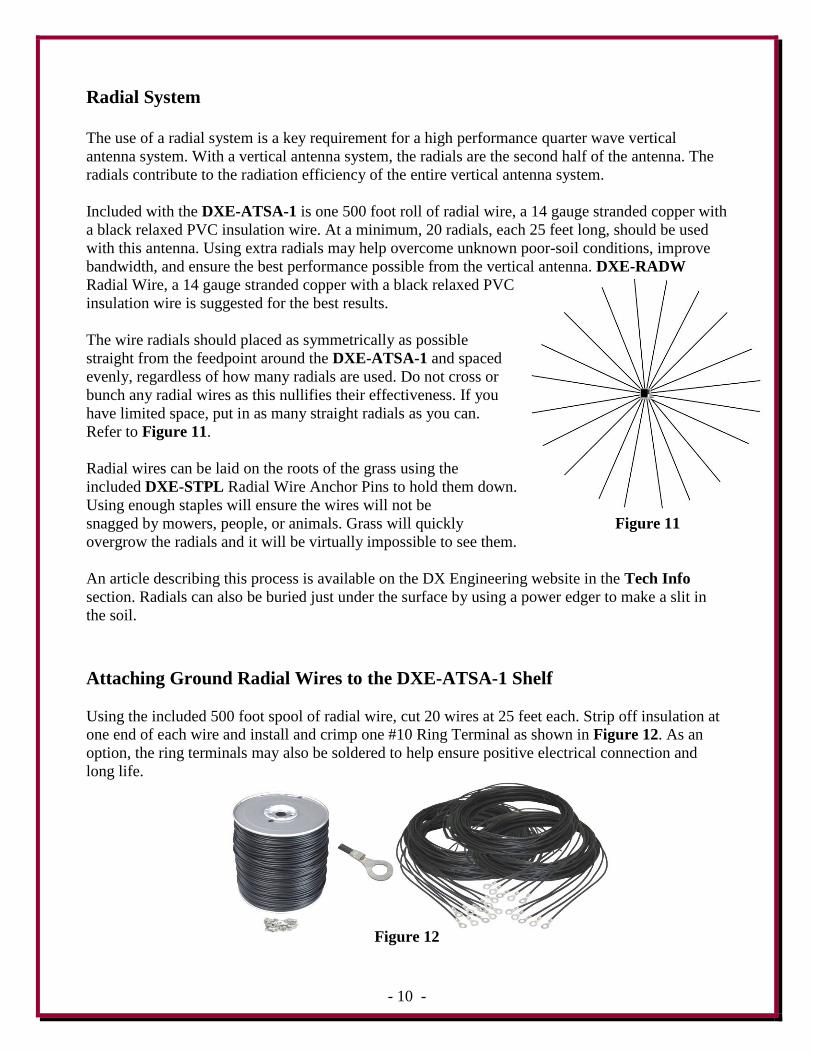
Radial System
The use of a radial system is a key requirement for a high performance quarter wave vertical
antenna system. With a vertical antenna system, the radials are the second half of the antenna. The
radials contribute to the radiation efficiency of the entire vertical antenna system.
Included with the DXE-ATSA-1 is one 500 foot roll of radial wire, a 14 gauge stranded copper with
a black relaxed PVC insulation wire. At a minimum, 20 radials, each 25 feet long, should be used
with this antenna. Using extra radials may help overcome unknown poor-soil conditions, improve
bandwidth, and ensure the best performance possible from the vertical antenna. DXE-RADW
Radial Wire, a 14 gauge stranded copper with a black relaxed PVC
insulation wire is suggested for the best results.
The wire radials should placed as symmetrically as possible
straight from the feedpoint around the DXE-ATSA-1 and spaced
evenly, regardless of how many radials are used. Do not cross or
bunch any radial wires as this nullifies their effectiveness. If you
have limited space, put in as many straight radials as you can.
Refer to Figure 11.
Radial wires can be laid on the roots of the grass using the
included DXE-STPL Radial Wire Anchor Pins to hold them down.
Using enough staples will ensure the wires will not be
snagged by mowers, people, or animals. Grass will quickly Figure 11
overgrow the radials and it will be virtually impossible to see them.
An article describing this process is available on the DX Engineering website in the Tech Info
section. Radials can also be buried just under the surface by using a power edger to make a slit in
the soil.
Attaching Ground Radial Wires to the DXE-ATSA-1 Shelf
Using the included 500 foot spool of radial wire, cut 20 wires at 25 feet each. Strip off insulation at
one end of each wire and install and crimp one #10 Ring Terminal as shown in Figure 12. As an
option, the ring terminals may also be soldered to help ensure positive electrical connection and
long life.
Figure 12
- 11 -
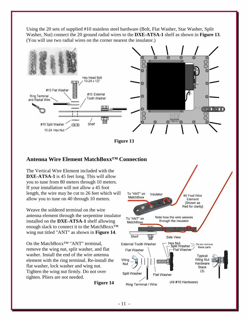
Using the 20 sets of supplied #10 stainless steel hardware (Bolt, Flat Washer, Star Washer, Split
Washer, Nut) connect the 20 ground radial wires to the DXE-ATSA-1 shelf as shown in Figure 13.
(You will use two radial wires on the corner nearest the insulator.)
Figure 13
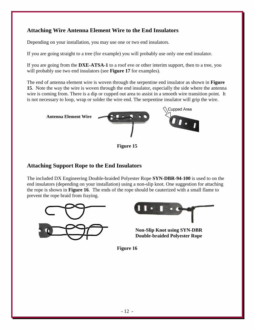
Antenna Wire Element MatchBoxx™ Connection
The Vertical Wire Element included with the
DXE-ATSA-1 is 45 feet long. This will allow
you to tune from 80 meters through 10 meters.
If your installation will not allow a 45 foot
length, the wire may be cut to 26 feet which will
allow you to tune on 40 through 10 meters.
Weave the soldered terminal on the wire
antenna element through the serpentine insulator
installed on the DXE-ATSA-1 shelf allowing
enough slack to connect it to the MatchBoxx™
wing nut titled "ANT" as shown in Figure 14.
On the MatchBoxx™ "ANT" terminal,
remove the wing nut, split washer, and flat
washer. Install the end of the wire antenna
element with the ring terminal. Re-install the
flat washer, lock washer and wing nut.
Tighten the wing nut firmly. Do not over
tighten. Pliers are not needed.
Figure 14
- 12 -
Attaching Wire Antenna Element Wire to the End Insulators
Depending on your installation, you may use one or two end insulators.
If you are going straight to a tree (for example) you will probably use only one end insulator.
If you are going from the DXE-ATSA-1 to a roof eve or other interim support, then to a tree, you
will probably use two end insulators (see Figure 17 for examples).
The end of antenna element wire is woven through the serpentine end insulator as shown in Figure
15. Note the way the wire is woven through the end insulator, especially the side where the antenna
wire is coming from. There is a dip or cupped out area to assist in a smooth wire transition point. It
is not necessary to loop, wrap or solder the wire end. The serpentine insulator will grip the wire.
Antenna Element Wire
Figure 15
Attaching Support Rope to the End Insulators
The included DX Engineering Double-braided Polyester Rope SYN-DBR-94-100 is used to on the
end insulators (depending on your installation) using a non-slip knot. One suggestion for attaching
the rope is shown in Figure 16. The ends of the rope should be cauterized with a small flame to
prevent the rope braid from fraying.
Non-Slip Knot using SYN-DBR
Double-braided Polyester Rope
Figure 16
- 13 -
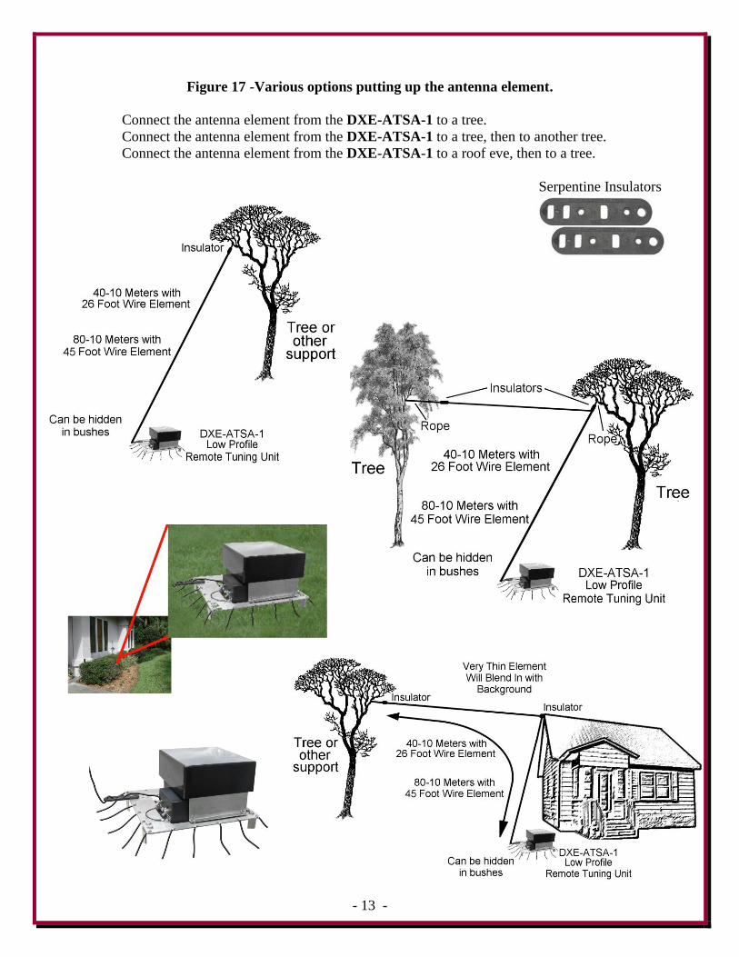
Figure 17 -Various options putting up the antenna element.
Connect the antenna element from the DXE-ATSA-1 to a tree.
Connect the antenna element from the DXE-ATSA-1 to a tree, then to another tree.
Connect the antenna element from the DXE-ATSA-1 to a roof eve, then to a tree.
Serpentine Insulators
- 14 -
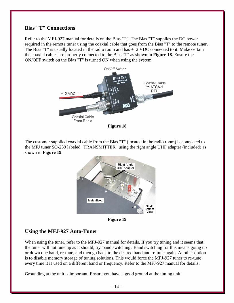
Bias "T" Connections
Refer to the MFJ-927 manual for details on the Bias "T". The Bias "T" supplies the DC power
required in the remote tuner using the coaxial cable that goes from the Bias "T" to the remote tuner.
The Bias "T" is usually located in the radio room and has +12 VDC connected to it. Make certain
the coaxial cables are properly connected to the Bias "T" as shown in Figure 18. Ensure the
ON/OFF switch on the Bias "T" is turned ON when using the system.
Figure 18
The customer supplied coaxial cable from the Bias "T" (located in the radio room) is connected to
the MFJ tuner SO-239 labeled "TRANSMITTER" using the right angle UHF adapter (included) as
shown in Figure 19.
Figure 19
Using the MFJ-927 Auto-Tuner
When using the tuner, refer to the MFJ-927 manual for details. If you try tuning and it seems that
the tuner will not tune up as it should, try 'band switching'. Band switching for this means going up
or down one band, re-tune, and then go back to the desired band and re-tune again. Another option
is to disable memory storage of tuning solutions. This would force the MFJ-927 tuner to re-tune
every time it is used on a different band or frequency. Refer to the MFJ-927 manual for details.
Grounding at the unit is important. Ensure you have a good ground at the tuning unit.
- 15 -
When installing the unit, the four ground
spikes must be pushed into the soil to
provide a good ground.
If your soil is not a good ground (sandy,
real hard dirt, etc.), adding a customer
supplied ground rod which is connected
to the unit at one of the radial
connection points will help provide a
good ground.
Please read and understand the instruction manual that comes with the MFJ-927 Remote
IntelliTuner™ Automatic Antenna Tuner. There is information included in that manual that
is critical to proper operation of both the MFJ-927 Remote IntelliTuner™ Automatic
Antenna Tuner and the Bias "T". There is also troubleshooting information and tuner reset
information that may be very helpful.
Removing the Tuner
To access the inside of the MFJ-927 tuner it will have to removed from the shelf. Remove your
coaxial cable from the right angle UHF adapter and remove the wire going from the tuner's red
binding post to the MatchBoxx™. Remove the four hex head bolts holding the tuner on the shelf as
shown in Figure 20.
Figure 20
Installing the Optional 80 meter Tuning Coil - DXE-SA80-AOK
The DXE-SA80-AOK 80 meter coil add-on kit is custom designed for use with the ATSA antenna
system. In some ATSA antenna installations with excellent radial systems, achieving the best SWR
on a vertical element for 80 meters may be difficult without some means of adjusting
feedpoint impedance.
- 16 -
The DXE-SA80-AOK allows easy adjustment for lowest SWR. The DXE-SA80-AOK will aid in
tuning a low impedance antenna to the minimum SWR in the customer selected portion of the 80
meter band without affecting operation on the other, higher frequency bands. The #12 AWG coil
wire is tin-nickel plated for high power handling, corrosion resistance, ease of soldering and long
term reliability.
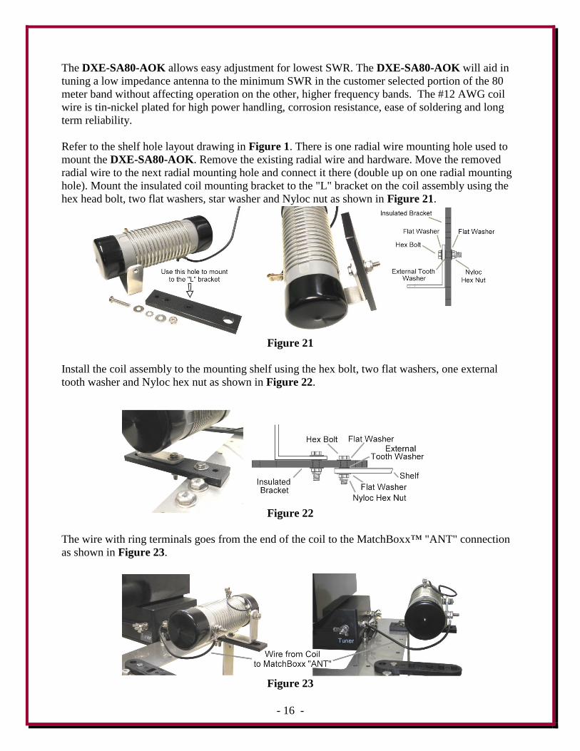
Refer to the shelf hole layout drawing in Figure 1. There is one radial wire mounting hole used to
mount the DXE-SA80-AOK. Remove the existing radial wire and hardware. Move the removed
radial wire to the next radial mounting hole and connect it there (double up on one radial mounting
hole). Mount the insulated coil mounting bracket to the "L" bracket on the coil assembly using the
hex head bolt, two flat washers, star washer and Nyloc nut as shown in Figure 21.
Figure 21
Install the coil assembly to the mounting shelf using the hex bolt, two flat washers, one external
tooth washer and Nyloc hex nut as shown in Figure 22.
Figure 22
The wire with ring terminals goes from the end of the coil to the MatchBoxx™ "ANT" connection
as shown in Figure 23.
Figure 23
- 17 -
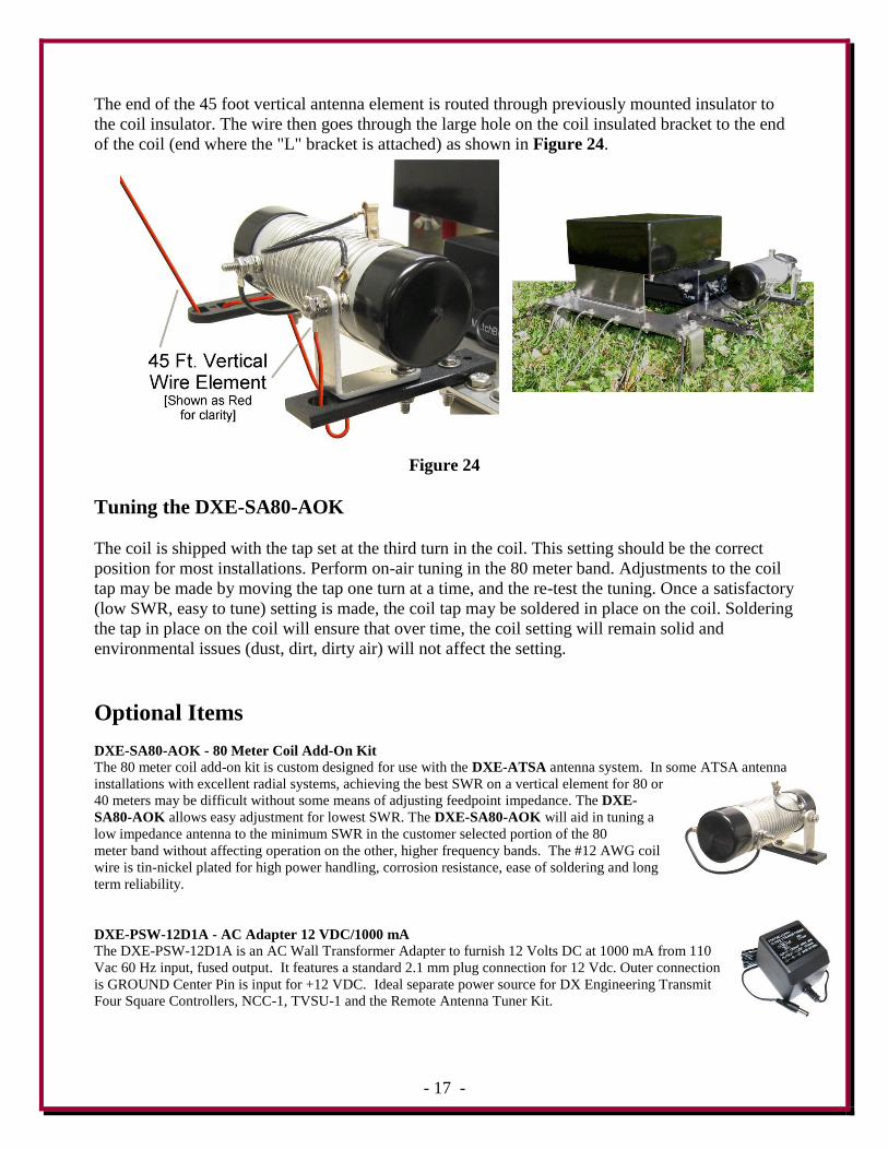
The end of the 45 foot vertical antenna element is routed through previously mounted insulator to
the coil insulator. The wire then goes through the large hole on the coil insulated bracket to the end
of the coil (end where the "L" bracket is attached) as shown in Figure 24.
Figure 24
Tuning the DXE-SA80-AOK
The coil is shipped with the tap set at the third turn in the coil. This setting should be the correct
position for most installations. Perform on-air tuning in the 80 meter band. Adjustments to the coil
tap may be made by moving the tap one turn at a time, and the re-test the tuning. Once a satisfactory
(low SWR, easy to tune) setting is made, the coil tap may be soldered in place on the coil. Soldering
the tap in place on the coil will ensure that over time, the coil setting will remain solid and
environmental issues (dust, dirt, dirty air) will not affect the setting.
Optional Items
DXE-SA80-AOK - 80 Meter Coil Add-On Kit
The 80 meter coil add-on kit is custom designed for use with the DXE-ATSA antenna system. In some ATSA antenna
installations with excellent radial systems, achieving the best SWR on a vertical element for 80 or
40 meters may be difficult without some means of adjusting feedpoint impedance. The DXE-
SA80-AOK allows easy adjustment for lowest SWR. The DXE-SA80-AOK will aid in tuning a
low impedance antenna to the minimum SWR in the customer selected portion of the 80
meter band without affecting operation on the other, higher frequency bands. The #12 AWG coil
wire is tin-nickel plated for high power handling, corrosion resistance, ease of soldering and long
term reliability.
DXE-PSW-12D1A - AC Adapter 12 VDC/1000 mA
The DXE-PSW-12D1A is an AC Wall Transformer Adapter to furnish 12 Volts DC at 1000 mA from 110
Vac 60 Hz input, fused output. It features a standard 2.1 mm plug connection for 12 Vdc. Outer connection
is GROUND Center Pin is input for +12 VDC. Ideal separate power source for DX Engineering Transmit
Four Square Controllers, NCC-1, TVSU-1 and the Remote Antenna Tuner Kit.
- 18 -
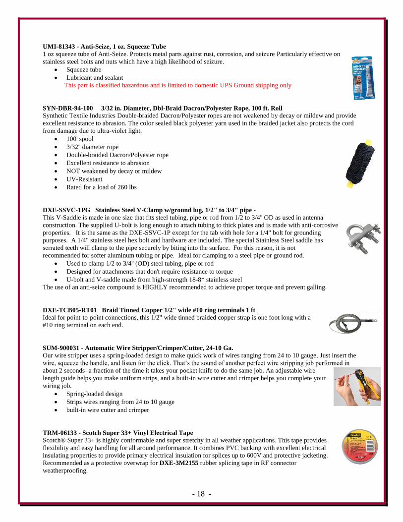
UMI-81343 - Anti-Seize, 1 oz. Squeeze Tube
1 oz squeeze tube of Anti-Seize. Protects metal parts against rust, corrosion, and seizure Particularly effective on
stainless steel bolts and nuts which have a high likelihood of seizure.
Squeeze tube
Lubricant and sealant
This part is classified hazardous and is limited to domestic UPS Ground shipping only
SYN-DBR-94-100 3/32 in. Diameter, Dbl-Braid Dacron/Polyester Rope, 100 ft. Roll
Synthetic Textile Industries Double-braided Dacron/Polyester ropes are not weakened by decay or mildew and provide
excellent resistance to abrasion. The color sealed black polyester yarn used in the braided jacket also protects the cord
from damage due to ultra-violet light.
100' spool
3/32'' diameter rope
Double-braided Dacron/Polyester rope
Excellent resistance to abrasion
NOT weakened by decay or mildew
UV-Resistant
Rated for a load of 260 lbs
DXE-SSVC-1PG Stainless Steel V-Clamp w/ground lug, 1/2" to 3/4" pipe -
This V-Saddle is made in one size that fits steel tubing, pipe or rod from 1/2 to 3/4'' OD as used in antenna
construction. The supplied U-bolt is long enough to attach tubing to thick plates and is made with anti-corrosive
properties. It is the same as the DXE-SSVC-1P except for the tab with hole for a 1/4" bolt for grounding
purposes. A 1/4" stainless steel hex bolt and hardware are included. The special Stainless Steel saddle has
serrated teeth will clamp to the pipe securely by biting into the surface. For this reason, it is not
recommended for softer aluminum tubing or pipe. Ideal for clamping to a steel pipe or ground rod.
Used to clamp 1/2 to 3/4'' (OD) steel tubing, pipe or rod
Designed for attachments that don't require resistance to torque
U-bolt and V-saddle made from high-strength 18-8* stainless steel
The use of an anti-seize compound is HIGHLY recommended to achieve proper torque and prevent galling.
DXE-TCB05-RT01 Braid Tinned Copper 1/2" wide #10 ring terminals 1 ft Ideal for point-to-point connections, this 1/2" wide tinned braided copper strap is one foot long with a
#10 ring terminal on each end.
SUM-900031 - Automatic Wire Stripper/Crimper/Cutter, 24-10 Ga. Our wire stripper uses a spring-loaded design to make quick work of wires ranging from 24 to 10 gauge. Just insert the
wire, squeeze the handle, and listen for the click. That’s the sound of another perfect wire stripping job performed in
about 2 seconds- a fraction of the time it takes your pocket knife to do the same job. An adjustable wire
length guide helps you make uniform strips, and a built-in wire cutter and crimper helps you complete your
wiring job.
Spring-loaded design
Strips wires ranging from 24 to 10 gauge
built-in wire cutter and crimper
TRM-06133 - Scotch Super 33+ Vinyl Electrical Tape
Scotch® Super 33+ is highly conformable and super stretchy in all weather applications. This tape provides
flexibility and easy handling for all around performance. It combines PVC backing with excellent electrical
insulating properties to provide primary electrical insulation for splices up to 600V and protective jacketing.
Recommended as a protective overwrap for DXE-3M2155 rubber splicing tape in RF connector
weatherproofing.
- 19 -
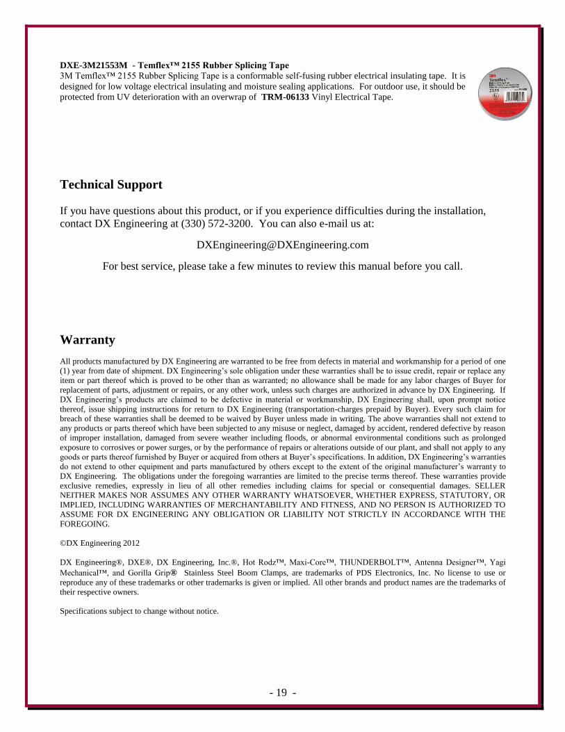
DXE-3M21553M - Temflex™ 2155 Rubber Splicing Tape
3M Temflex™ 2155 Rubber Splicing Tape is a conformable self-fusing rubber electrical insulating tape. It is
designed for low voltage electrical insulating and moisture sealing applications. For outdoor use, it should be
protected from UV deterioration with an overwrap of TRM-06133 Vinyl Electrical Tape.
Technical Support
If you have questions about this product, or if you experience difficulties during the installation,
contact DX Engineering at (330) 572-3200. You can also e-mail us at:
For best service, please take a few minutes to review this manual before you call.
Warranty
All products manufactured by DX Engineering are warranted to be free from defects in material and workmanship for a period of one
(1) year from date of shipment. DX Engineering’s sole obligation under these warranties shall be to issue credit, repair or replace any
item or part thereof which is proved to be other than as warranted; no allowance shall be made for any labor charges of Buyer for
replacement of parts, adjustment or repairs, or any other work, unless such charges are authorized in advance by DX Engineering. If
DX Engineering’s products are claimed to be defective in material or workmanship, DX Engineering shall, upon prompt notice
thereof, issue shipping instructions for return to DX Engineering (transportation-charges prepaid by Buyer). Every such claim for
breach of these warranties shall be deemed to be waived by Buyer unless made in writing. The above warranties shall not extend to
any products or parts thereof which have been subjected to any misuse or neglect, damaged by accident, rendered defective by reason
of improper installation, damaged from severe weather including floods, or abnormal environmental conditions such as prolonged
exposure to corrosives or power surges, or by the performance of repairs or alterations outside of our plant, and shall not apply to any
goods or parts thereof furnished by Buyer or acquired from others at Buyer’s specifications. In addition, DX Engineering’s warranties
do not extend to other equipment and parts manufactured by others except to the extent of the original manufacturer’s warranty to
DX Engineering. The obligations under the foregoing warranties are limited to the precise terms thereof. These warranties provide
exclusive remedies, expressly in lieu of all other remedies including claims for special or consequential damages. SELLER
NEITHER MAKES NOR ASSUMES ANY OTHER WARRANTY WHATSOEVER, WHETHER EXPRESS, STATUTORY, OR
IMPLIED, INCLUDING WARRANTIES OF MERCHANTABILITY AND FITNESS, AND NO PERSON IS AUTHORIZED TO
ASSUME FOR DX ENGINEERING ANY OBLIGATION OR LIABILITY NOT STRICTLY IN ACCORDANCE WITH THE
FOREGOING.
©DX Engineering 2012
DX Engineering®, DXE®, DX Engineering, Inc.®, Hot Rodz™, Maxi-Core™, THUNDERBOLT™, Antenna Designer™, Yagi
Mechanical™, and Gorilla Grip® Stainless Steel Boom Clamps, are trademarks of PDS Electronics, Inc. No license to use or
reproduce any of these trademarks or other trademarks is given or implied. All other brands and product names are the trademarks of
their respective owners.
Specifications subject to change without notice.