Embed Size (px)
DESCRIPTION
civil engineering
Citation preview
Journal of Constructional Steel Research 65 (2009) 260–268
Contents lists available at ScienceDirect
Journal of Constructional Steel Research
journal homepage: www.elsevier.com/locate/jcsr
Evaluation of yielding shear panel device for passive energy dissipationRicky W.K. Chan a,b, Faris Albermani b,∗, Martin S. Williams c
a City University of Hong Kong, Hong Kongb University of Queensland, Australiac University of Oxford, UK
a r t i c l e i n f o
Article history:Received 17 October 2007Accepted 25 March 2008
Keywords:Yielding shear panelEnergy dissipationSeismic retrofitting
a b s t r a c t
The paper describes an experimental investigation of a new earthquake damper, the yielding shear paneldevice (YSPD), for civil structures. It utilizes energy dissipation through plastic shear deformation of a thindiaphragm steel plate welded inside a square hollow section (SHS). Its performance is verified by nineteenmonotonic and cyclic tests. Experiments showed that certain specimens exhibited stable behavior andwere capable of dissipating a significant amount of energy. The performance is influenced by thediaphragm plate slenderness and by the in-plane rigidity of the surrounding SHS. Slender plates undergoelastoplastic shear buckling and exhibit stable though slightly pinched hysteresis response. Stocky platesimpose high deformation demand on the surrounding SHS that hinders their cyclic performance. Theequivalent viscous damping offered by the test specimens, on their own, and the cumulative energydissipation are quantified. Fabrication, implementation and replacement of the damper proved to be easyand inexpensive. The YSPD offers a potentially viable alternative for seismic retrofitting of existing framestructures.
© 2008 Elsevier Ltd. All rights reserved.
1. Introduction
Interest in the development of passive energy dissipation inearthquake risk mitigation of civil structures has greatly increasedin the last two decades. [1,2] During an earthquake, a largeamount of energy is imparted to a structure. The traditionaldesign approach relies on the energy dissipation as a consequenceof inelastic deformation of particular structural zones. Thepermanent damage of the post-disaster structure is often soserious that it would be expensive to repair, if at all possible. Theconcept of passive energy dissipation, however, attempts to reducesuch permanent damage to the structure. With designated energydissipative devices installed within a structure, a portion of theinput seismic energy could be diverted into these devices; as aresult damage of the parent structure can be effectively reduced.The inclusion of dissipative devices in a structure is expected toalter its stiffness and damping and hence influence its structuralresponse [3]. In addition, by strategically locating these devices,repair and/or replacement of the devices following an earthquakecan be carried out with minimal interruption to occupancy, acrucial benefit to building owners and occupants.
A number of dissipative devices utilizing plastic deformation ofmetals have been proposed. Devices which make use of flexural
∗ Corresponding author. Tel.: +61 7 3365 4126; fax: +61 7 3365 4599.E-mail address: [email protected] (F. Albermani).
0143-974X/$ – see front matter © 2008 Elsevier Ltd. All rights reserved.doi:10.1016/j.jcsr.2008.03.017
deformation of metals include the patented ADAS [4], its variantsTADAS [5] and Cu-ADAS [6] and the Steel Slit Damper (SSD) [7]. TheBuckling-restrained brace (BRB) [8], on the other hand, makes useof the axial deformation of steel.
Devices such as the ADAS, SSD and the proposed YSPD areusually envisaged to be connected between the top of an invertedV-brace (chevron brace) system and a floor beam in a structuralpanel (Fig. 1). This results in the device being connected in seriesto the bracing system. The resultant in-plane lateral stiffness ofthe brace-device assembly kbd, can be obtained from the individualstiffness of the brace, kb, and the device, kd,
kbd =1
1kb+
1kd
=kbkd
kb + kd. (1)
Eq. (1) indicates that the brace stiffness is compromised by theinsertion of a flexible damper. If the brace stiffness is required towithstand in-service lateral loads, a relatively high device-to-bracestiffness is then necessary. Dampers which rely on plastic flexuraldeformation are generally flexible; hence multiple plates are usedto build up the required stiffness.
On the other hand, the in-plane shear strength and stiffness ofsteel plates has been used by designers as a primary lateral loadresistant system. The steel plate shear wall (SPSW) is one suchapplication that has been used in Europe, North America and Japan.The SPSW provides high in-plane stiffness to resist lateral loadsand represents an alternative to conventional reinforced concretewalls. Thin steel plates buckle elastically at a rather low level
R.W.K. Chan et al. / Journal of Constructional Steel Research 65 (2009) 260–268 261
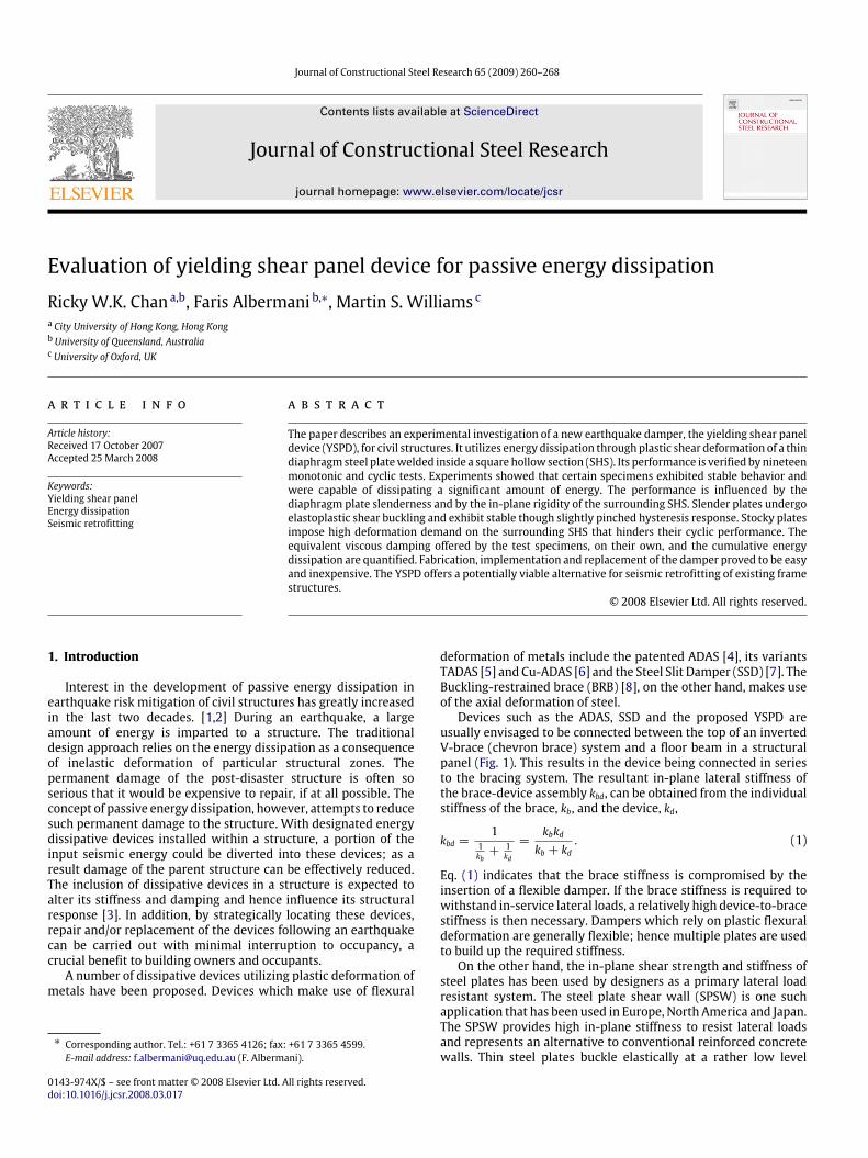
Fig. 1. Frame-brace-device assembly.
of shear stress; however plate buckling is not synonymous withfailure if the plate is adequately supported along its boundaries.Basler [9] demonstrated that in the presence of tension field action,steel plates offer substantially higher strength and ductility thanconcrete walls. The cyclic behavior of steel plate shear wall panelshas been investigated by a number of researchers [10–13].
Generally, a good metallic device for seismic applicationsmust exhibit: (1) adequate elastic stiffness to withstand in-service lateral load (e.g. wind); (2) a yield strength of thedamper exceeding the expected in-service lateral loads; (3)large energy dissipative capability; and (4) a stable hystereticforce–displacement response which can be modeled numerically.
To utilize the high in-plane stiffness and energy dissipativecapability of shearing actions in steel plates, a new metallicdamper, the Yielding Shear Panel Device (YSPD) has been proposedby Schmidt et al. [14] and further developed by Williams andAlbermani [15]. They performed quasi-static tests on a half-scaledmoment resisting frame equipped with a YSPD and showed thata considerable amount of energy was dissipated through thedamper [15].
This paper concentrates on the performance of the YSPDitself (isolated from the parent frame structure). A series of sub-assemblage tests on half-scaled YSPD specimens is conducted. Aspecially designed test setup was developed for this purpose. Atotal of 19 tests were conducted using various plate slendernessand device configurations. These tests are presented and discussedin this paper. In addition a simple analytical design method of thedevice is presented together with a hysteretic model that can becalibrated using the obtained experimental results.
2. Yielding shear panel device (YSPD)
Figs. 2 and Fig. 8 show the yielding shear panel device tested inthis research. It was fabricated using a short segment of a squarehollow section (SHS, dimension D × DxT) with a steel diaphragmplate (thickness t) welded inside it. The square section was chosenin this study since it was expected to be more effective than arectangular section in developing 45 degree tension field.
The length of the SHS section was chosen to equal its width(i.e. D). The relative horizontal displacement between the top andbottom connections causes the diaphragm plate to deform in shear(Fig. 2(c)). When the displacement is sufficiently large the platedeforms plastically, and as a result input energy is dissipated.Fabrication and installation of the device is simple and inexpensive.
3. Preliminary design of YSPD
Assuming a minor contribution from SHS, the theoretical elasticin-plane lateral stiffness of the device kd is given by,
kd = Gtd/d = Gt (2)
Fig. 2. Yielding shear panel device (YSPD) (a) Elevation (b) Top view (c) Deformedshape.
where G is shear modulus and t is the thickness of the diaphragmplate. For a compact diaphragm plate the yield strength can betaken as the shear yield strength (assuming a von Mises yieldcriterion);
Fy =fy√
3td (3)
where d is the width of steel plate and fy is its tensile yield stress.Consequently, the yield displacement of the device is,
uy =Fykd=
fyd√
3G. (4)
For a device with a slender diaphragm plate, elastic shear bucklingwill take place. The critical shear stress for a simply supported plateis given by,
τcr = ksπ2E
12(1− ν2)
(t
d
)2(5)
where ks depends on the aspect ratio of the plate, and equals 9.35for square plates. E and ν are Young’s modulus and Poisson’s ratiorespectively. Taking ν = 0.3 and E = 205 GPa, the limiting plateslenderness ratio at which buckling occurs is
d/t = 1732/√fy (6)
where fy is the tensile yield strength of the diaphragm plate (MPa).
4. Test program
Performance of passive energy devices is often influencedby factors such as connection details, the surrounding SHS andpossible fabrication flaws. Therefore, it is essential to conducta testing program to verify the cyclic performance and energydissipation capacity of the proposed YSPD.
4.1. Specimens
Twelve specimens similar to Fig. 2 were fabricated at thestructures laboratory of the City University of Hong Kong. Twodifferent SHS sections (100×100×4 and 120×120×5) and threediaphragm plate thicknesses (2, 3, and 4 mm) were used, resulting

262 R.W.K. Chan et al. / Journal of Constructional Steel Research 65 (2009) 260–268
Table 1Material properties for test specimens
Elements Measured thickness (mm) Tensile yield strength (N/mm2)
2 mm PL 1.86 211.33 mm PL 2.83 321.34 mm PL 3.78 351.2100× 100× 4 3.76 414.9120× 120× 5 4.91 333.3
Table 2Test specimen details
Test no. Specimen SHS Test regime Plate slenderness
1 100-0M
Monotonic
–2 100-2M 49.53 100-3M 32.54 100-4M 24.35 100-0C 100× 100× 4
Cyclic
–6 100-2C 49.57 100-3C 32.58 100-4C 24.39 100-2CS 49.5
10 100-3CS 32.511 100-4CS 24.312 120-0M
Monotonic
–13 120-2M 59.114 120-3M 38.915 120-4M 120× 120× 5 29.116 120-0C
Cyclic
–17 120-2C 59.118 120-3C 38.919 120-4C 29.1
in six different diaphragm plate-to-SHS combinations. Slendernessratios of all diaphragm plates are lower than the elastic bucklinglimit of Eq. (6). Four bolt holes spaced at s = 50 mm were drilled oneach of the two opposite SHS flanges for connecting the specimento the test setup (Fig. 2). The square diaphragm plates (d×d) werecut to slightly smaller than the internal dimensions of the SHS. Thefour corners were coped, and then the plate was positioned insidethe SHS, spot-welded at four corners and subsequently weldedalong the plate’s edges from both sides. The fillet weld’s leg sizewas approximately 3 mm.
Experimental details are listed in Tables 1 and 2. The measuredplate and wall thicknesses are listed in Table 1 together with themeasured yield stress from coupon tests. The measured diaphragmplate thicknesses are within 86%–96% of the nominal thickness. Thefollowing notation is adopted to identify different specimens usedin the test; D− tM or D− tC, where D indicates the size of the SHSsection (either 100 or 120 mm), t is the thickness of the diaphragmplate used (either 2, 3 or 4 mm). A zero plate thickness indicatesno diaphragm plate is used inside the SHS. The letter M indicates amonotonic test while C is a cyclic test. Three specimens are shownas 100-2CS, 100-3CS and 100-4CS; here the S indicates a stiffenedsection (Fig. 3).
Four control tests of SHS without a diaphragm plate wereconducted to identify the contribution of the SHS. Further, in orderto investigate the effect of stiffening of the SHS connecting flanges,three additional specimens with stiffened flanges were fabricated.In these specimens, two pieces of 19.5 mm thick mild steel plateswere welded to the two connected flanges of the SHS as shown inFig. 3.
4.2. Test setup and instrumentation
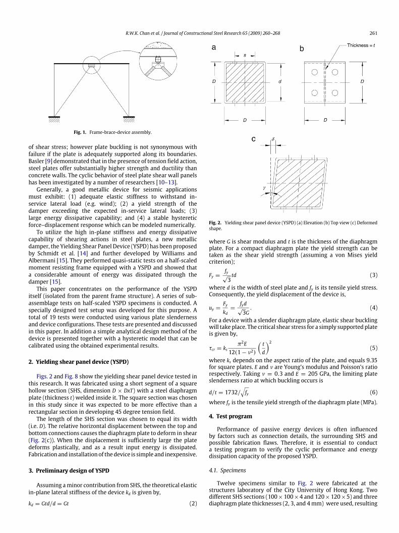
Fig. 4 shows a schematic view and Fig. 5 an overview of theexperimental platform used in this study. The test specimens wereinstalled between a ground beam and an L-beam, securely fastenedby four M16 bolts (snug tight) on each side. Forced displacement
Fig. 3. YSPD with stiffened flanges.
was applied by an MTS 100 kN capacity computer-controlledactuator quasi-statically to the specimen via the L-beam. To ensurethe verticality of the applied load, a pantograph system was weldedto the right hand side of the L-beam. To prevent the L-beamfrom deflecting out-of-plane, lateral supports (with rollers) wereinitially provided (not shown for clarity). However, these supportswere later removed as it was noticed that the pantograph systemwas adequate to prevent the L-girder from deflecting out-of-plane. The complete test setup rested on a reaction frame whichwas significantly stiffer. The centerline of the actuator implied aneccentricity, e, to the specimen. A free-run of the setup (i.e. withoutthe specimen installed) was performed, and the result showed thateffect of friction and gravity was negligible.
Following the ECCS recommendation for simulating groundmotion [16], a quasi-static loading history comprised of 3 repeatedcycles at 0.5, 1.0, 3.0, 5.0, 10.0 and 20.0 mm amplitudes (atotal of 18 cycles) as shown in Fig. 6 was adopted. A positiveamplitude indicates a downward movement of the actuator.Based on previous test results conducted on a half-scaled bracedframe [15], a maximum amplitude of 20 mm of device deformationcorresponds to 2.67% drift factor which is more than thepermissible drift limit used in practice [14].
Displacements of the specimens were measured independentlyby a set of LVDT’s, marked as 1 through 3 in Fig. 4. While LVDT1 measures the elastic deformation of the support, the differenceacross LVDT 1 and 2 measured the absolute deformation of the testspecimen. With LVDT 3 and the distance between LVDT 2 and 3measured, in-plane rotation of the L-beam could be monitored. Formonotonic tests, strain rosette gages were positioned at the centerof the diaphragm plates to monitor the actual strain behavior.
4.3. Test observations
The test setup was robust and repeatable, and no visibledamage occurred after all tests were carried out. The pantographsystem effectively restrained the force delivery vertically. In-planerotation of the L-beam were measured (LVDT 2 and 3) and itwas found to be less than one degree. Its effect is considerednegligible. The ground support deflection (LVDT 1) was elastic.Average shear strain of specimens is defined as γ = δ/D, whereδ is the displacement difference across LVDT 1 and 2.
4.3.1. Monotonic testsMonotonic tests were terminated when the actuator reached
an absolute displacement of 20 mm. Due to elastic deformationof the experimental setup, the deformation of the test specimens(difference across LVDT 1 and 2) is less than the imposed
R.W.K. Chan et al. / Journal of Constructional Steel Research 65 (2009) 260–268 263
Fig. 4. Experimental setup.
Table 3Summary of monotonic test results
Specimen Experimental PredictedInitial stiffness (kN/mm) Yield (kN) Yield disp. (mm) Ω10 Initial stiffness (kN/mm)
(Eq. (2))Yield (kN)(Eq. (3))
Elastic buckling (kN)(Eq. (5))
100-0M 1.3 6.3 5.2 1.34 – – –100-2M 14.6 22.1 1.8 1.59 130.2 22.7 111.5100-3M 26.3 27.4 1.2 1.77 198.1 52.5 392.6100-4M 29.4 30.8 1.2 2.32 264.6 76.6 935.7120-0M 2.4 6.3 3.5 1.40 – – –120-2M 44.9 15.7 0.7 2.51 132.3 26.1 97.5120-3M 18.5 37.1 2.6 1.64 198.1 63.0 327.2120-4M 58.9 17.7 0.7 4.03 256.2 89.1 707.8
Fig. 5. Overview of test setup.
displacement. Control tests of the SHS without diaphragm platesindicated low stiffness and yield strengths (Table 3), suggestingthat the contribution of the SHS is minimal.
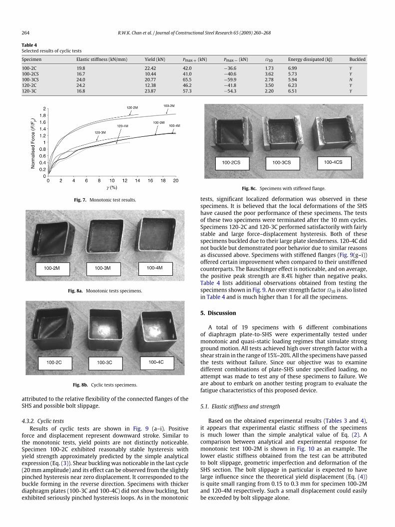
Normalized force-shear strain curves of monotonic tests areshown in Fig. 7. Distinct yield points were not noticeable; insteadthere was a smooth transition from the elastic to inelastic regime.Yielding is taken at 0.2% strain offset and is shown in Table 3. Anover strength factor Ω10, defined as the force sustained at a shearstrain γ = 10%, divided by the experimental yield strength is alsoshown in Table 3. All the specimens offer an over strength fac-tor much higher than 1. The nominated 10% strain corresponds to1.5% inter-story drift factor which is consistent with practical lim-its [15].
Fig. 6. Displacement history for cyclic tests.
The 2 mm specimens (100-2M and 120-2M) performedsimilarly, with strength approaching 1.8Fy towards the end ofthe tests. These two specimens, unlike other specimens withthicker diaphragm plates, showed inelastic shear buckling (Fig. 8a).Specimens with 3 and 4 mm diaphragm plates were not ableto reach a force higher than the theoretical yield strength (Eq.(3)). A closer inspection of these specimens after test revealedlocalized distortion of the SHS. Due to the high in-plane stiffnessof the thicker plates, the SHS sustained more deformation. Thedeformation was mainly in the vicinity of bolt holes and at mid-length of the SHS where the diaphragm plate is welded. The poorperformance of specimens with thicker diaphragm plates can be
264 R.W.K. Chan et al. / Journal of Constructional Steel Research 65 (2009) 260–268
Table 4Selected results of cyclic tests
Specimen Elastic stiffness (kN/mm) Yield (kN) Pmax+ (kN) Pmax− (kN) Ω10 Energy dissipated (kJ) Buckled
100-2C 19.8 22.42 42.0 −36.6 1.73 6.99 Y100-2CS 16.7 10.44 41.0 −40.6 3.62 5.73 Y100-3CS 24.0 20.77 65.5 −59.9 2.78 5.94 N120-2C 24.2 12.38 46.2 −41.8 3.50 6.23 Y120-3C 16.8 23.87 57.3 −54.3 2.20 6.51 Y
Fig. 7. Monotonic test results.
Fig. 8a. Monotonic tests specimens.
Fig. 8b. Cyclic tests specimens.
attributed to the relative flexibility of the connected flanges of theSHS and possible bolt slippage.
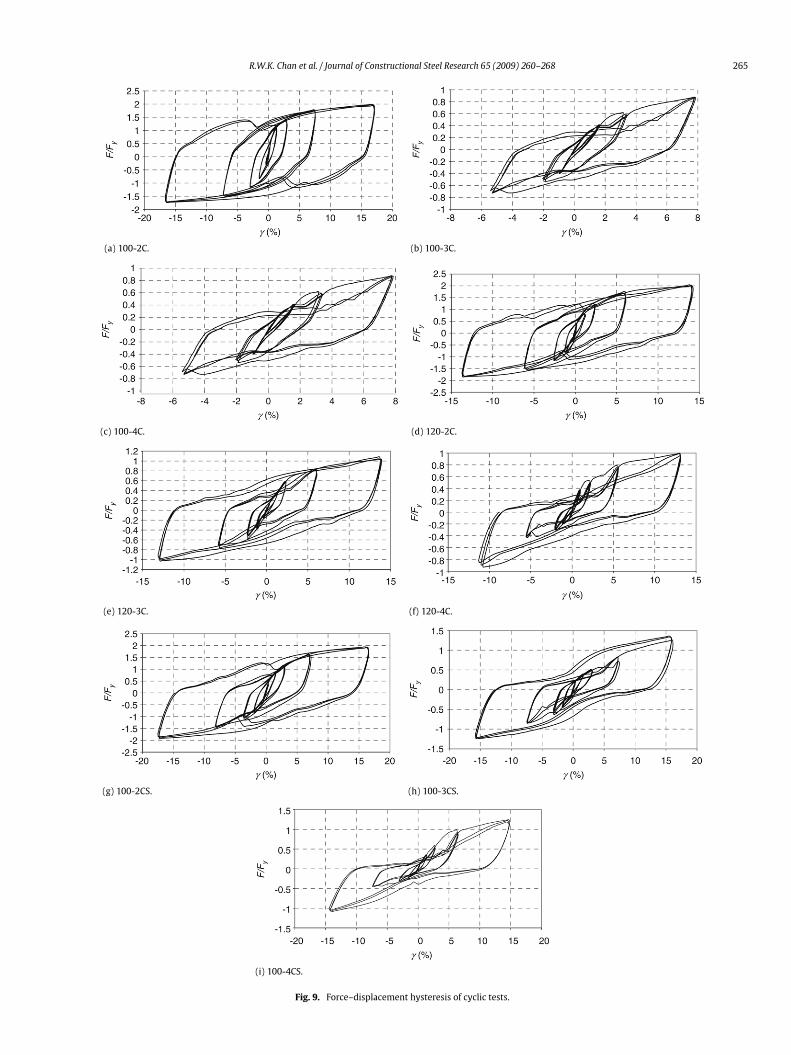
4.3.2. Cyclic testsResults of cyclic tests are shown in Fig. 9 (a–i). Positive
force and displacement represent downward stroke. Similar tothe monotonic tests, yield points are not distinctly noticeable.Specimen 100-2C exhibited reasonably stable hysteresis withyield strength approximately predicted by the simple analyticalexpression (Eq. (3)). Shear buckling was noticeable in the last cycle(20 mm amplitude) and its effect can be observed from the slightlypinched hysteresis near zero displacement. It corresponded to thebuckle forming in the reverse direction. Specimens with thickerdiaphragm plates (100-3C and 100-4C) did not show buckling, butexhibited seriously pinched hysteresis loops. As in the monotonic
Fig. 8c. Specimens with stiffened flange.
tests, significant localized deformation was observed in thesespecimens. It is believed that the local deformations of the SHShave caused the poor performance of these specimens. The testsof these two specimens were terminated after the 10 mm cycles.Specimens 120-2C and 120-3C performed satisfactorily with fairlystable and large force–displacement hysteresis. Both of thesespecimens buckled due to their large plate slenderness. 120-4C didnot buckle but demonstrated poor behavior due to similar reasonsas discussed above. Specimens with stiffened flanges (Fig. 9(g–i))offered certain improvement when compared to their unstiffenedcounterparts. The Bauschinger effect is noticeable, and on average,the positive peak strength are 8.4% higher than negative peaks.Table 4 lists additional observations obtained from testing thespecimens shown in Fig. 9. An over strength factor Ω10 is also listedin Table 4 and is much higher than 1 for all the specimens.
5. Discussion
A total of 19 specimens with 6 different combinationsof diaphragm plate-to-SHS were experimentally tested undermonotonic and quasi-static loading regimes that simulate strongground motion. All tests achieved high over strength factor with ashear strain in the range of 15%–20%. All the specimens have passedthe tests without failure. Since our objective was to examinedifferent combinations of plate-SHS under specified loading, noattempt was made to test any of these specimens to failure. Weare about to embark on another testing program to evaluate thefatigue characteristics of this proposed device.
5.1. Elastic stiffness and strength
Based on the obtained experimental results (Tables 3 and 4),it appears that experimental elastic stiffness of the specimensis much lower than the simple analytical value of Eq. (2). Acomparison between analytical and experimental response formonotonic test 100-2M is shown in Fig. 10 as an example. Thelower elastic stiffness obtained from the test can be attributedto bolt slippage, geometric imperfection and deformation of theSHS section. The bolt slippage in particular is expected to havelarge influence since the theoretical yield displacement (Eq. (4))is quite small ranging from 0.15 to 0.3 mm for specimen 100-2Mand 120-4M respectively. Such a small displacement could easilybe exceeded by bolt slippage alone.
R.W.K. Chan et al. / Journal of Constructional Steel Research 65 (2009) 260–268 265
(a) 100-2C. (b) 100-3C.
(c) 100-4C. (d) 120-2C.
(e) 120-3C. (f) 120-4C.
(g) 100-2CS. (h) 100-3CS.
(i) 100-4CS.
Fig. 9. Force–displacement hysteresis of cyclic tests.

266 R.W.K. Chan et al. / Journal of Constructional Steel Research 65 (2009) 260–268
Fig. 10. Comparison between experimental and predicted results for 100-2M.
Fig. 11. Maximum principal strain measured on diaphragm plates.
Fig. 12. Principal tensile strain angle.
All the specimens offered quite good over strength factorswhich were generally much higher than 1. Although the simpleanalytical model (Eqs. (2) and (3)) over-estimates the elasticstiffness and under-estimate the capacity, it remains a useful toolfor preliminary selection of the device.
5.2. Principal strains
Principal strains in the plate diaphragms under monotonicloading were obtained using rosette gages. Fig. 11 shows theprincipal strain plotted against the normalized applied load forvarious monotonic tests. From this figure it appears that nearlyall specimens start yielding at approximately 0.7F/Fy, with thebuckled specimens 100-2M and 120-2M offering the highest strainhardening. Fig. 12 shows the measured direction of principal strainat the center of the diaphragm plates with respect to the horizontaldirection. Specimen 100-2M clearly maintains the principal strainclose to 45 degrees in both pre- and post-buckling stages. Thisobservation indicates an approximate pure-shear condition wasset in the pre-buckling stage and a tension field was formeddiagonally within the square plate confined by the SHS in the post-buckling stage.
Fig. 13. Cumulative energy dissipation of specimens.
Fig. 14. Effective stiffness and energy dissipated in a cycle.
5.3. Energy dissipation
The cumulative energy dissipation of the cyclic test specimensis plotted as a function of cumulative device displacement inFig. 13. Specimen 100-2C dissipated the largest amount of energy(close to 7 kJ) among the tested combinations. This specimen alsooffers the highest rate of dissipation. Specimen 120-3C and 120-2Cfollowed. Again, specimens with higher plate slenderness offer su-perior performance, and inelastic shear buckling did not cause in-stability of the device. Stiffened specimen 100-2CS dissipated theleast energy among the tests. The decrease in energy dissipationmay be attributed to an increase in eccentricity due to the stiff-ening plates. This increase in eccentricity between the centerlineof applied load and the centerline of the specimen will make thestress field in the diaphragm plate deviate from a pure shear state.This will require further investigation on the effect of eccentricity.
5.4. Equivalent device stiffness and damping
It is generally accepted that energy dissipated in cyclic strainingof metals is rate-independent. For practical use it is sometimespreferable to express the device properties in an equivalent viscoussystem. This is basically a single degree of freedom oscillator withan equivalent stiffness keff defined as (see Fig. 14),
keff =|Pmax| − |Pmin|
|δmax| − |δmin|. (7)
R.W.K. Chan et al. / Journal of Constructional Steel Research 65 (2009) 260–268 267
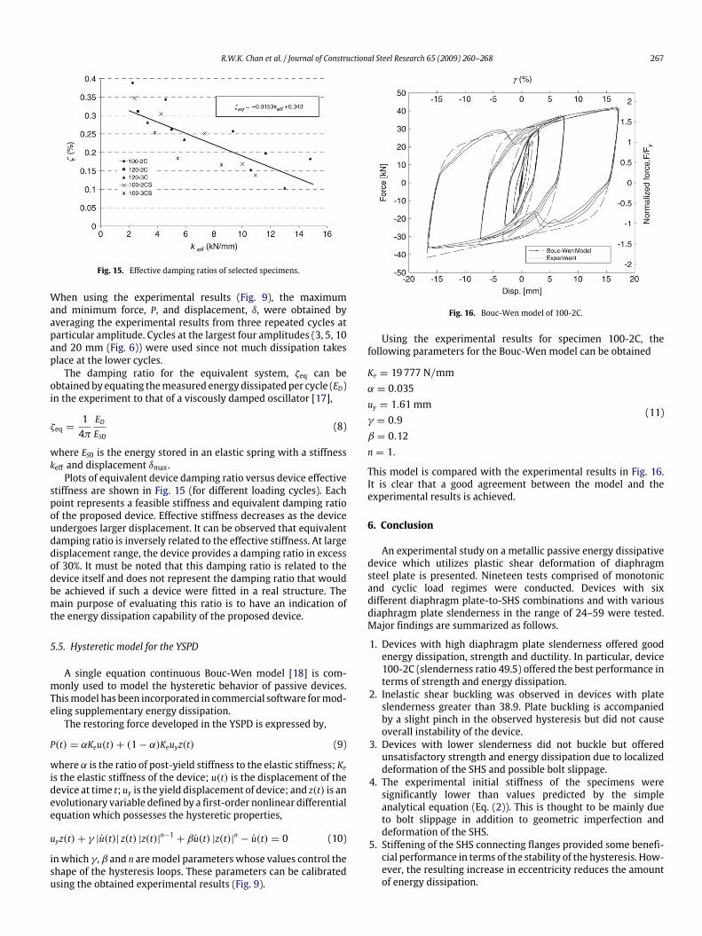
Fig. 15. Effective damping ratios of selected specimens.
When using the experimental results (Fig. 9), the maximumand minimum force, P, and displacement, δ, were obtained byaveraging the experimental results from three repeated cycles atparticular amplitude. Cycles at the largest four amplitudes (3, 5, 10and 20 mm (Fig. 6)) were used since not much dissipation takesplace at the lower cycles.
The damping ratio for the equivalent system, ζeq can beobtained by equating the measured energy dissipated per cycle (ED)in the experiment to that of a viscously damped oscillator [17],
ζeq =1
4πEDES0
(8)
where ES0 is the energy stored in an elastic spring with a stiffnesskeff and displacement δmax.
Plots of equivalent device damping ratio versus device effectivestiffness are shown in Fig. 15 (for different loading cycles). Eachpoint represents a feasible stiffness and equivalent damping ratioof the proposed device. Effective stiffness decreases as the deviceundergoes larger displacement. It can be observed that equivalentdamping ratio is inversely related to the effective stiffness. At largedisplacement range, the device provides a damping ratio in excessof 30%. It must be noted that this damping ratio is related to thedevice itself and does not represent the damping ratio that wouldbe achieved if such a device were fitted in a real structure. Themain purpose of evaluating this ratio is to have an indication ofthe energy dissipation capability of the proposed device.
5.5. Hysteretic model for the YSPD
A single equation continuous Bouc-Wen model [18] is com-monly used to model the hysteretic behavior of passive devices.This model has been incorporated in commercial software for mod-eling supplementary energy dissipation.
The restoring force developed in the YSPD is expressed by,
P(t) = αKeu(t)+ (1− α)Keuyz(t) (9)
where α is the ratio of post-yield stiffness to the elastic stiffness; Ke
is the elastic stiffness of the device; u(t) is the displacement of thedevice at time t; uy is the yield displacement of device; and z(t) is anevolutionary variable defined by a first-order nonlinear differentialequation which possesses the hysteretic properties,
uyz(t)+ γ |u(t)| z(t) |z(t)|n−1+ βu(t) |z(t)|n − u(t) = 0 (10)
in which γ, β and n are model parameters whose values control theshape of the hysteresis loops. These parameters can be calibratedusing the obtained experimental results (Fig. 9).
Fig. 16. Bouc-Wen model of 100-2C.
Using the experimental results for specimen 100-2C, thefollowing parameters for the Bouc-Wen model can be obtained
Ke = 19 777 N/mmα = 0.035uy = 1.61 mmγ = 0.9β = 0.12n = 1.
(11)
This model is compared with the experimental results in Fig. 16.It is clear that a good agreement between the model and theexperimental results is achieved.
6. Conclusion
An experimental study on a metallic passive energy dissipativedevice which utilizes plastic shear deformation of diaphragmsteel plate is presented. Nineteen tests comprised of monotonicand cyclic load regimes were conducted. Devices with sixdifferent diaphragm plate-to-SHS combinations and with variousdiaphragm plate slenderness in the range of 24–59 were tested.Major findings are summarized as follows.
1. Devices with high diaphragm plate slenderness offered goodenergy dissipation, strength and ductility. In particular, device100-2C (slenderness ratio 49.5) offered the best performance interms of strength and energy dissipation.
2. Inelastic shear buckling was observed in devices with plateslenderness greater than 38.9. Plate buckling is accompaniedby a slight pinch in the observed hysteresis but did not causeoverall instability of the device.
3. Devices with lower slenderness did not buckle but offeredunsatisfactory strength and energy dissipation due to localizeddeformation of the SHS and possible bolt slippage.
4. The experimental initial stiffness of the specimens weresignificantly lower than values predicted by the simpleanalytical equation (Eq. (2)). This is thought to be mainly dueto bolt slippage in addition to geometric imperfection anddeformation of the SHS.
5. Stiffening of the SHS connecting flanges provided some benefi-cial performance in terms of the stability of the hysteresis. How-ever, the resulting increase in eccentricity reduces the amountof energy dissipation.

268 R.W.K. Chan et al. / Journal of Constructional Steel Research 65 (2009) 260–268
6. The energy dissipation capability of the YSPD can be repre-sented by an equivalent damping ratio. This damping ratio canbe in excess of 30% at large displacement range.
7. The YSPD response can be simulated using a Bouc-Wenhysteretic model calibrated against the obtained experimentalresults.
References
[1] Soong TT, Dargush GF. Passive energy dissipation systems in structuralengineering. John Wiley & Sons; 1997.
[2] Soong TT, Spencer Jr BF. Supplemental energy dissipation: State-of-the-art andstate-of-the-practice. Eng Struct 2002;24:243–59.
[3] Whittaker AS, Bertero VV, Thompson CL, Alonso LJ. Seismic testing of steelplate energy dissipation devices. Earthq Spectra 1991;7(4):563–604.
[4] Bergman DM, Goel SC. Evaluation of cyclic testing of steel plate devices foradded damping and stiffness. Report no. UMCE87-10. Ann Arbor (MI, USA):The University of Michigan; 1987.
[5] Tsai K, Chen H, Hong C, Su Y. Design of steel triangular plate energy absorbersfor seimic-resistant construction. Earthquake Spectra 1993;9(3):505–28.
[6] De la Llera J, Esguerra C, Almazan JL. Earthquake behavior of structures withcopper energy dissipators. Earthq Eng Struct Dyn 2004;33:329–58.
[7] Chan RWK, Albermani F. Experimental study of steel slit damper for passiveenergy dissipation. Eng Struct 2007. doi:10.1016/j.engstruct.2007.07.005.
[8] Clark PW, Aiken ID, Tajirian F, Kasai K, Ko E, Kimura I. Design proceduresfor buildings incorporating hysteretic damping devices. In: Proc. int. post-SmiRT conf. seminar on seismic isolation, passive energy dissipation and activecontrol of vibrations of structures. 1999.
[9] Basler K. Strength of plate girders in shear. J Struct Div, ASCE 1961;87(7).[10] Elgaaly M, Caccese V, Du C. Postbuckling behavior of steel-plate shear walls
under cyclic loads. J Struct Engrg 1993;119(2).[11] Driver RG, Kulak GL, Kennedy DJK, Elwi AE. Cyclic test of four-story steel plate
shear wall. J Struct Engrg, ASCE 1998;124(2).[12] Lubell AS, Prion HGL, Ventura CE, Rezai M. Unstiffened steel plate shear wall
performance under cyclic loading. J Struct Engrg, ASCE 2000;126(4).[13] Vian D, Bruneau M. Testing of special LYS steel plate shear walls. Paper no. 978.
In: 13th WCEE. 2004.[14] Schmidt K, Dorka UE, Taucer F, Magnonette G. Seismic retrofit of a steel
frame and an RC frame with HYDE systems. Institute for the Protection andthe Security of the Citizen European Laboratory for Structural Assessment.European Commission Joint Research Centre; 2004.
[15] Williams MS, Albermani F. Monotonic and cyclic tests on shear diaphragmdissipaters for steel frames. Adv Steel Constr 2006;2(1):1–21.
[16] European Convention for Construction of Steelworks. Recommended testingprocedure for assessing the behaviour of steel elements under cyclic loads.Technical Committee 1. TWG 1.3. 1986.
[17] Chopra AK. Dynamics of structures: Theory and applications to earthquakeengineering. Englewood Cliffs (NJ): Prentice Hall; 1995.
[18] Wen YK. Method for random vibration of hysteretic systems. J Engr Mech1976;102:249–63.


![Estimating number of simultaneously yielding …bruneau/Engineering Structures 2017b... · Estimating number of simultaneously yielding stories in a shear building ... [3], [4])](https://img.pdfslide.us/doc/110x75/5b5df2587f8b9a057e8b49d8/estimating-number-of-simultaneously-yielding-bruneauengineering-structures-2017b.jpg)