Embed Size (px)
Citation preview

Seats and Restraint Systems ........................... 1-1Front Seats ............................................... 1-2Rear Seats ............................................... 1-6Safety Belts ............................................. 1-23Child Restraints ....................................... 1-42Airbag System ......................................... 1-77Restraint System Check ............................ 1-91
Features and Controls ..................................... 2-1Keys ........................................................ 2-3Doors and Locks ...................................... 2-10Windows ................................................. 2-24Theft-Deterrent Systems ............................ 2-27Starting and Operating Your Vehicle ........... 2-31Mirrors .................................................... 2-43Object Detection Systems .......................... 2-44OnStar® System ...................................... 2-47Universal Home Remote System ................ 2-51Storage Areas ......................................... 2-56
Instrument Panel ............................................. 3-1Instrument Panel Overview .......................... 3-4Climate Controls ...................................... 3-24Warning Lights, Gages, and Indicators ........ 3-34Driver Information Center (DIC) .................. 3-50Audio System(s) ....................................... 3-84
Driving Your Vehicle ....................................... 4-1Your Driving, the Road, and Your Vehicle ..... 4-2Towing ................................................... 4-27
Service and Appearance Care .......................... 5-1Service ..................................................... 5-3Fuel ......................................................... 5-5Checking Things Under the Hood ............... 5-10Headlamp Aiming ..................................... 5-41Bulb Replacement .................................... 5-42Windshield Wiper Blade Replacement ......... 5-47Tires ...................................................... 5-48Appearance Care ..................................... 5-90Vehicle Identification ................................. 5-98Electrical System ...................................... 5-99Capacities and Specifications ................... 5-105
Maintenance Schedule ..................................... 6-1Maintenance Schedule ................................ 6-2
Customer Assistance Information .................... 7-1Customer Assistance and Information ........... 7-2Reporting Safety Defects ........................... 7-14Vehicle Data Recording and Privacy ........... 7-16
Index ................................................................ 1
2008 Chevrolet Uplander Owner Manual M

GENERAL MOTORS, GM, the GM Emblem,CHEVROLET, the CHEVROLET Emblem, and thename UPLANDER are registered trademarks ofGeneral Motors Corporation.
This manual includes the latest information at the time itwas printed. We reserve the right to make changesafter that time without further notice. For vehicles firstsold in Canada, substitute the name “General Motors ofCanada Limited” for Chevrolet Motor Division wheneverit appears in this manual.
This manual describes features that may be available inthis model, but your vehicle may not have all of them.For example, more than one entertainment system maybe offered or your vehicle may have been orderedwithout a front passenger or rear seats.
Keep this manual in the vehicle, so it will be there if it isever needed when you are on the road. If the vehicleis sold, leave this manual in the vehicle.
Canadian OwnersA French language copy of this manual can be obtainedfrom your dealer/retailer or from:
Helm, IncorporatedP.O. Box 07130Detroit, MI 48207
1-800-551-4123www.helminc.com
Propriétaires CanadiensOn peut obtenir un exemplaire de ce guide en françaisauprès de concessionnaire ou à l’adresse suivante:
Helm IncorporatedP.O. Box 07130Detroit, MI 48207
1-800-551-4123www.helminc.com
Using this ManualMany people read the owner manual from beginningto end when they first receive their new vehicle tolearn about the vehicle’s features and controls.Pictures and words work together to explain things.
Litho in U.S.A.Part No. 15869263 A First Printing ©2007 General Motors Corporation. All Rights Reserved.
ii

IndexA good place to quickly locate information about thevehicle is the Index in the back of the manual. It isan alphabetical list of what is in the manual andthe page number where it can be found.
Safety Warnings and SymbolsThere are a number of safety cautions in this book.A box with the word CAUTION is used to tell aboutthings that could hurt you or others if you were toignore the warning.
{CAUTION:
These mean there is something that could hurtyou or other people.
We tell you what the hazard is and what to do to helpavoid or reduce the hazard. Please read these cautions.If you do not, you or others could be hurt.
A circle with a slashthrough it is a safetysymbol which means“Do Not,” “Do Not dothis” or “Do Not letthis happen.”
iii

Vehicle Damage WarningsYou will also find notices in this manual.
Notice: These mean there is something that coulddamage your vehicle.
A notice tells about something that can damage thevehicle. Many times, this damage would not be coveredby your vehicle’s warranty, and it could be costly.The notice tells what to do to help avoid the damage.
When you read other manuals, you might see CAUTIONand NOTICE warnings in different colors or in differentwords.
There are also warning labels on the vehicle which usethe same words, CAUTION or NOTICE.
Vehicle SymbolsThe vehicle has components and labels that usesymbols instead of text. Symbols are shown along withthe text describing the operation or informationrelating to a specific component, control, message,gage, or indicator.
iv

Front Seats ......................................................1-2Manual Seats ................................................1-2Power Seats ..................................................1-3Heated Seats .................................................1-3Reclining Seatbacks ........................................1-4Head Restraints .............................................1-6
Rear Seats .......................................................1-6Rear Seat Operation .......................................1-6Bucket Seats .................................................1-6Captain Chairs .............................................1-14Third Row Seat ............................................1-18
Safety Belts ...................................................1-23Safety Belts: They Are for Everyone ................1-23How to Wear Safety Belts Properly .................1-28Lap-Shoulder Belt .........................................1-36Safety Belt Use During Pregnancy ..................1-41Safety Belt Extender .....................................1-42
Child Restraints .............................................1-42Older Children ..............................................1-42Infants and Young Children ............................1-46Child Restraint Systems .................................1-49Where to Put the Restraint .............................1-52
Lower Anchors and Tethers forChildren (LATCH) ......................................1-53
Securing a Child Restraint in aRear Seat Position ....................................1-61
Securing a Child Restraint in theRight Front Seat Position ............................1-64
Built-In Child Restraint ...................................1-68Airbag System ...............................................1-77
Where Are the Airbags? ................................1-80When Should an Airbag Inflate? .....................1-82What Makes an Airbag Inflate? .......................1-83How Does an Airbag Restrain? .......................1-83What Will You See After an
Airbag Inflates? .........................................1-84Passenger Sensing System ............................1-85Servicing Your Airbag-Equipped Vehicle ...........1-90Adding Equipment to Your Airbag-Equipped
Vehicle ....................................................1-90Restraint System Check ..................................1-91
Checking the Restraint Systems ......................1-91Replacing Restraint System Parts
After a Crash ............................................1-92
Section 1 Seats and Restraint Systems
1-1

Front Seats
Manual Seats
Use the lever located onthe front of the seat toadjust the seat forward orrearward. Pull up onthe lever to unlock theseat. Slide the seatto where you want it andrelease the lever.
{CAUTION:
You can lose control of the vehicle if you try toadjust a manual driver’s seat while the vehicleis moving. The sudden movement could startleand confuse you, or make you push a pedalwhen you do not want to. Adjust the driver’sseat only when the vehicle is not moving.
To make sure the seat is locked into place, try to movethe seat back and forth with your body.
1-2

Power Seats
If the vehicle has powerseats, the controls used tooperate them are locatedon the outboard side ofthe seats.
To adjust the seat, do any of the following:
• Move the seat forward or rearward by sliding thecontrol forward or rearward.
• Raise or lower the front part of the seat cushion bymoving the front of the control up or down.
• Raise or lower the rear part of the seat cushion bymoving the rear of the control up or down.
Heated SeatsYour vehicle may have this feature. If it does, the heatedseat buttons are located on the climate control panel.
This feature will heat the lower cushions of the driver’sand front passenger’s seats.
Press this button onceto turn the heated seaton to the high setting.
Both indicator lights next to the heated seat symbolwill be lit to indicate that it is on the high setting.Press the button a second time to go to the low setting.One indicator will be lit. Press the button a third timeto turn the heated seat off.
This feature will turn off automatically when theignition is turned off.
Driver’s Side Buttonshown, Passenger’s
Side similar
1-3

Reclining Seatbacks
{CAUTION:
You can lose control of the vehicle if you try toadjust a manual driver’s seat while the vehicleis moving. The sudden movement could startleand confuse you, or make you push a pedalwhen you do not want to. Adjust the driver’sseat only when the vehicle is not moving.
{CAUTION:
If the seatback is not locked, it could moveforward in a sudden stop or crash. That couldcause injury to the person sitting there. Alwayspush and pull on the seatback to be sure itis locked.
Your seats have manual reclining seatbacks. The leverused to operate them is located on the outboard side ofthe seats.
1. Lift the recline lever.2. Move the seatback to the desired position, then
release the lever to lock the seatback in place.3. Push and pull on the seatback to make sure it
is locked.
To return the seatback to an upright position, do thefollowing:
1. Lift the lever fully without applying pressure to theseatback and the seatback will return to the uprightposition.
2. Push and pull on the seatback to make sure itis locked.
1-4

{CAUTION:
Sitting in a reclined position when your vehicleis in motion can be dangerous. Even if youbuckle up, your safety belts cannot do theirjob when you are reclined like this.
The shoulder belt cannot do its job because itwill not be against your body. Instead, it will bein front of you. In a crash, you could go into it,receiving neck or other injuries.
The lap belt cannot do its job either. In a crash,the belt could go up over your abdomen. Thebelt forces would be there, not at your pelvicbones. This could cause serious internalinjuries.
For proper protection when the vehicle is inmotion, have the seatback upright. Then sitwell back in the seat and wear your safety beltproperly.
Do not have a seatback reclined if your vehicle is moving.
1-5

Head Restraints
Adjust the head restraint so that the top of the restraintis at the same height as the top of the occupant’shead. This position reduces the chance of a neck injuryin a crash.The height of the head restraints can be adjusted onthe first and second row seats. Pull the head restraintup or push it down to adjust it.The head restraints on the third row seat cannot beadjusted.
Rear Seats
Rear Seat OperationThe rear seats in your vehicle have levers and strapsused to adjust, remove, and reinstall the seats. By usingthe levers and straps in the correct order, you caneasily remove the seats from the vehicle. If your vehiclehas second row captain chairs with airbags, the seatscannot be removed.
When reinstalling the seats, make sure the seats are inthe proper positions.
If your vehicle has a second row center console, it canbe removed. See Second Row Center Console onpage 2-59. Do not put a seat in the center positionbecause the safety belt cannot be worn properly in thisposition. See Safety Belts: They Are for Everyoneon page 1-23.
Bucket SeatsYour vehicle may have bucket seats in the second row.These seats can be adjusted several different ways.
1-6
Fold and Tumble Feature
{CAUTION:
Using the third row seating position while thesecond row is folded, or folded and tumbled,could cause injury in a sudden stop or crash.Be sure to return the seat to the passengerseating position. Push and pull on the seat tomake sure it is locked into place.
The second row bucket seats can be folded andtumbled forward. Use this feature for exiting andentering third row seats, if the vehicle has them.
1. Make sure the adjustable head restraints are inthe fully lowered position.
Notice: Folding a rear seat with the safety beltsstill fastened may cause damage to the seat or thesafety belts. Always unbuckle the safety beltsand return them to their normal stowed positionbefore folding a rear seat.
2. Fold the seatback flaton the seat.
You can do this by either pulling on the nylon strap,located on the rear right hand side of the seat, orby lifting the recline lever, located on the front righthand side of the seatback.
3. Slide the seat all the way back in this position.
1-7
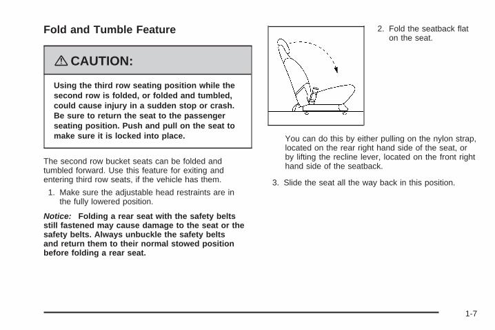
4. Release the rear set ofseat hooks from thefloor pins by pulling thenylon strap, locatedat the base of the seat.Use the strap toguide the seat forward.
To return the seat to the original position, do thefollowing:
1. Align the seat so that the rear hooks on the seatare over the rear floor pins. Push down firmly onthe rear of the seat so that the rear hooks attachto the rear floor pins.
2. Try to raise the seat to check that it is locked tothe floor.
3. Pull the nylon strap, located on the rear right handside of the seat, or lift the recline lever, locatedon the front right hand side of the seatback, toraise the seatback to the upright position.
{CAUTION:
If the seatback is not locked, it could moveforward in a sudden stop or crash. That couldcause injury to the person sitting there. Alwayspush and pull on the seatback to be sure itis locked.
4. Push and pull on the seatback to check that itis locked.
One of the bucket seats may be equipped with a built-inchild restraint. See Built-In Child Restraint on page 1-68.
1-8

Adjusting the Bucket Seats Forwardand RearwardThere are two adjustment levers on the second rowbucket seats that enable them to move forward orrearward.
One is located below the front of the seat.
The other lever is locatedon the rear of the seat.
To adjust the second row bucket seats forward orrearward, do the following:
1. Lift up either lever and slide the seat forward orrearward.
2. Release the lever when the seat is in the desiredposition.
3. Push and pull on the seat to make sure it is locked.
1-9

Folding or Reclining the SeatbacksThe seatback on a bucket seat can either be foldedforward or reclined using the nylon strap or therecline lever.
To fold the seatback forward, do the following:
1. Pull the nylon strap, located on the rear right handside of the seat, or lift the recline lever, locatedon the front right hand side of the seatbackto release the seatback.
Notice: Folding a rear seat with the safety beltsstill fastened may cause damage to the seat or thesafety belts. Always unbuckle the safety beltsand return them to their normal stowed positionbefore folding a rear seat.
2. Fold the seatback forward.
{CAUTION:
If the seatback is not locked, it could moveforward in a sudden stop or crash. That couldcause injury to the person sitting there. Alwayspush and pull on the seatback to be sure itis locked.
To raise the seatback to the upright position from areclined position, do the following:
1. Pull the nylon strap or lift the recline lever whileraising the seatback until it locks to the uprightposition.
2. Push and pull on the seatback to check that itis locked.
Nylon Strap Recline Lever
1-10

To recline the seatback, do the following:
1. Pull the nylon strap or lift the recline lever.
2. Press back on the seatback until it is in thedesired position
3. Let go of the strap or lever.
Removing the Bucket SeatsTo remove the bucket seats, do the following:
1. Make sure the head restraint is in the fullylowered position.
Notice: Folding a rear seat with the safety beltsstill fastened may cause damage to the seat or thesafety belts. Always unbuckle the safety beltsand return them to their normal stowed positionbefore folding a rear seat.
2. Fold the seatback flat on the seat, by either pullingon the nylon strap, located on the rear right handside of the seat, or by lifting the recline lever,located on the front right hand side of the seatback.
3. Lift either one of the adjuster levers and slide theseat to the most rearward position. See “Adjustingthe Bucket Seats Forward and Rearward” earlierin this section.
4. Release the rear set of hooks from the floor pins bypulling the nylon strap, located at the base of theseat. Use the strap to guide the seat forward.
1-11

5. To release the front seat hooks from the floor pins,squeeze the angled bar, located beneath the seattoward the straight crossbar.
6. Remove the seat by rocking it slightly forward, thentoward the rear of the vehicle while pulling it out.This should be done in one motion.
Reinstalling the Bucket Seats
{CAUTION:
A safety belt that is improperly routed, notproperly attached, or twisted will not providethe protection needed in a crash. The personwearing the belt could be seriously injured.After installing the seat, always check to besure that the safety belts are properly routedand attached, and are not twisted.
Do not install the seat facing the rear of the vehicle,as it will not lock into place. If more storage roomis needed behind the seat, slide the seat forward.
Make sure the seat is in the full rear position beforebeginning this procedure.
1-12

To reinstall the bucket seats, do the following:
1. With the seat folded, squeeze the angled barbeneath the seat toward the straight crossbar,while placing the front hooks of the seat intothe front two floor pins.
2. Make sure the seat isangled so that thefront seat hooksclear the floor pins.If the front hooksare not attachedcorrectly, the seat’srear hooks willnot attach to therear set of floor pins.
If the front hooks are not attaching correctly,check that the seat is in the full rear position.
3. Firmly push the rear seat hooks into the rear floorpins by pushing down the rear of the seat.
{CAUTION:
A seat that is not locked into place properlycan move around in a collision or sudden stop.People in the vehicle could be injured. Be sureto lock the seat into place properly wheninstalling it.
4. Check that the seat is locked by trying to raisethe seat.
1-13

5. Pull the nylon strap, located on the rear right handside of the seat, or lift the recline lever, locatedon the front right hand side of the seatback,to raise the seatback to the upright position.
{CAUTION:
If the seatback is not locked, it could moveforward in a sudden stop or crash. That couldcause injury to the person sitting there. Alwayspush and pull on the seatback to be sure itis locked.
6. Push and pull on the seatback to make sure thatit is locked.
Captain ChairsYour vehicle may have second row captain chairs.If so, they can be adjusted forward or rearward andthe seatbacks can be adjusted.
Adjusting the Captain Chairs Forwardand RearwardThere are two manual adjustment bars on each seat.One is located under the front of the seat cushion.The other one is located under the rear of the seatcushion.
Lift up either bar to slide the seat forward or rearward.Release the lever. Push and pull on the seat tomake sure it is locked into place.
1-14

Folding or Reclining the Seatbacks
{CAUTION:
If the seatback is not locked, it could moveforward in a sudden stop or crash. That couldcause injury to the person sitting there. Alwayspush and pull on the seatback to be sure itis locked.
To recline the seatback, lift up on the recliner leverlocated on the outboard side of the seat, then movethe seatback to the desired position.To raise the seatback, lift up on the recliner leverwithout applying pressure to the seatback. Push andpull on the seatback to make sure it is locked in place.
Notice: Folding a rear seat with the safety beltsstill fastened may cause damage to the seat or thesafety belts. Always unbuckle the safety beltsand return them to their normal stowed positionbefore folding a rear seat.To fold the seatback forward, lift up fully on the reclinerlever. Push the seatback forward until it is flat.
1-15

The armrests can be lowered or raised for easierentry or exit of the vehicle. If your vehicle hascaptain chairs with side impact airbags, they willhave one armrest on the inboard side.
Removing a Captain Chair(without a Side Impact Airbag)If your vehicle has captain chairs with side impactairbags, the seats cannot be removed. See Where Arethe Airbags? on page 1-80 for more information.
To remove a captain chair, do the following:
1. Pull the nylon strap behind the seat to release therear hooks from the floor pins.
2. The seat can then be lifted off the front floor pinsand removed from the vehicle.
1-16

Installing a Captain Chair(without a Side Impact Airbag)
{CAUTION:
A safety belt that is improperly routed, notproperly attached, or twisted will not providethe protection needed in a crash. The personwearing the belt could be seriously injured.After installing the seat, always check to besure that the safety belts are properly routedand attached, and are not twisted.
Do not put the seats in so they face rearward becausethey will not latch that way. For the second row,if you want more storage room behind the seat,adjust the seat by sliding it forward.
Make sure the seatbacks are in the upright position,the seat belts are on the correct side of the seats andthe seats are in the full rear position before beginningthis procedure.
To install a captain chair, do the following:
1. Hook the front latches over the front floor pins.
1-17

2. Push the rear of the seat down to lock the rearlatches onto the rear set of floor pins.
{CAUTION:
A seat that is not locked into place properlycan move around in a collision or sudden stop.People in the vehicle could be injured. Be sureto lock the seat into place properly wheninstalling it.
3. Push and pull on the seat to be sure it is properlyattached.
Third Row SeatYour vehicle may have a third row seat. It is a fullbench seat and may come with the convenience center.See Convenience Center on page 2-62 for moreinformation. The third row seat can be removed andreplaced, or with the seatback folded, it will lie flat withthe convenience center.
1-18

Folding the Seatback(s)
Notice: Folding a rear seat with the safety beltsstill fastened may cause damage to the seat or thesafety belts. Always unbuckle the safety beltsand return them to their normal stowed positionbefore folding a rear seat.
To fold down either side of the 50/50 split bench seat,lift the lever located on the back of the seat you want tofold, and push the seatback down.
Returning the Seatback to anUpright Position
{CAUTION:
If the seatback is not locked, it could moveforward in a sudden stop or crash. That couldcause injury to the person sitting there. Alwayspush and pull on the seatback to be sure it islocked.
To raise the seatback, do the following:
1. Move the second row seat completely forward byusing the manual adjustment bar under either thefront or rear of the seat cushion.
2. Open the liftgate.
1-19

3. From the rear of the vehicle, locate the pullstrapattached to the lever on the back of the seat andpull it to raise the seat.
4. Push and pull on the seatback to make sure that itis locked into place.
Removing the Third Row Seat1. Remove the convenience center, if equipped.
See Convenience Center on page 2-62 for moreinformation.
2. Make sure all items are off the seat.
Notice: Folding a rear seat with the safety beltsstill fastened may cause damage to the seat or thesafety belts. Always unbuckle the safety beltsand return them to their normal stowed positionbefore folding a rear seat.
3. Put the seatback in its folded position beforeremoving the seat. See “Folding the Seatback(s)”earlier in this section.
1-20

4. From behind the seat, squeeze the release handleuntil the pin indicators are fully out. This indicatesthat the rear latches are released from the floor.For ease of removing the seat, squeeze the handlewith the palm of your hand up.
5. Lift the seat slightly from the floor to ensure thelatches are clear of the floor pins.
6. Pull the seat rearward and out of the vehicle.The release handle can be used to carry the seat.
Installing the Third Row Seat
{CAUTION:
A safety belt that is improperly routed, notproperly attached, or twisted will not providethe protection needed in a crash. The personwearing the belt could be seriously injured.After installing the seat, always check to besure that the safety belts are properly routedand attached, and are not twisted.
Do not put the third row seat in so it faces rearwardbecause it will not latch that way. The seat needsto be installed before the convenience center. SeeConvenience Center on page 2-62 for more information.
Notice: Folding a rear seat with the safety beltsstill fastened may cause damage to the seat or thesafety belts. Always unbuckle the safety beltsand return them to their normal stowed positionbefore folding a rear seat.
1-21

For ease of installing the seat, put the seat in the foldedposition before beginning this procedure.
1. From the rear of the vehicle, place the front hooksof the seat onto the front floor pins in the third row.To do this, the seat will need to be angledapproximately 8-10 inches (20-25 cm) from thefloor so the front hooks clear the rear floor pinsand rear floor cups. Use the release handle toguide the seat into place.If the front hooks are not attached correctly,the rear latches will not attach to the rear setof floor pins.
2. Firmly push the rear latches into the rear floorpins by pushing down on the rear of the seat.
{CAUTION:
A seat that is not locked into place properlycan move around in a collision or sudden stop.People in the vehicle could be injured. Be sureto lock the seat into place properly wheninstalling it.
3. Try to raise the seat to make sure that it is lockeddown. The indicator pins will no longer stick outwhen the seat is properly latched into place.
{CAUTION:
If the seatback is not locked, it could moveforward in a sudden stop or crash. That couldcause injury to the person sitting there. Alwayspush and pull on the seatback to be sure itis locked.
4. Return the seatback to its upright position. See“Returning the Seatback to an Upright Position”earlier in this section.
1-22

Safety Belts
Safety Belts: They Are for EveryoneThis part of the manual tells you how to use safetybelts properly. It also tells you some things you shouldnot do with safety belts.
{CAUTION:
Do not let anyone ride where he or she cannotwear a safety belt properly. If you are in acrash and you are not wearing a safety belt,your injuries can be much worse. You canhit things inside the vehicle harder or beejected from it and be seriously injured orkilled. In the same crash, you might not be,if you are buckled up. Always fasten yoursafety belt, and check that your passenger(s)are restrained properly too.
{CAUTION:
It is extremely dangerous to ride in a cargoarea, inside or outside of a vehicle. In acollision, people riding in these areas are morelikely to be seriously injured or killed. Do notallow people to ride in any area of your vehiclethat is not equipped with seats and safetybelts. Be sure everyone in your vehicle is in aseat and using a safety belt properly.
Your vehicle has indicators as a reminder to buckle yoursafety belts. See Safety Belt Reminders on page 3-36.In most states and in all Canadian provinces, thelaw requires wearing safety belts. Here is why:You never know if you will be in a crash. If you do havea crash, you do not know if it will be a serious one.A few crashes are mild, and some crashes can be soserious that even buckled up, a person would not survive.But most crashes are in between. In many of them, peoplewho buckle up can survive and sometimes walk away.Without belts they could have been badly hurt or killed.After more than 40 years of safety belts in vehicles,the facts are clear. In most crashes buckling up doesmatter... a lot!
1-23

Why Safety Belts WorkWhen you ride in or on anything, you go as fast as it goes.
Take the simplest vehicle. Suppose it is just a seat onwheels.
Put someone on it.
1-24

Get it up to speed. Then stop the vehicle.The rider does not stop.
The person keeps going until stopped by something.In a real vehicle, it could be the windshield...
1-25

or the instrument panel... or the safety belts!
With safety belts, you slow down as the vehicle does.You get more time to stop. You stop over more distance,and your strongest bones take the forces. That is whysafety belts make such good sense.
1-26
Questions and Answers AboutSafety Belts
Q: Will I be trapped in the vehicle after a crash ifI am wearing a safety belt?
A: You could be — whether you are wearing a safetybelt or not. But your chance of being consciousduring and after an accident, so you can unbuckleand get out, is much greater if you are belted.And you can unbuckle a safety belt, even if youare upside down.
Q: If my vehicle has airbags, why should I haveto wear safety belts?
A: Airbags are supplemental systems only; so theywork with safety belts — not instead of them.Whether or not an airbag is provided, all occupantsstill have to buckle up to get the most protection.That is true not only in frontal collisions, butespecially in side and other collisions.
Q: If I am a good driver, and I never drive far fromhome, why should I wear safety belts?
A: You may be an excellent driver, but if you are ina crash — even one that is not your fault — youand your passenger(s) can be hurt. Being agood driver does not protect you from thingsbeyond your control, such as bad drivers.
Most accidents occur within 25 miles (40 km)of home. And the greatest number of seriousinjuries and deaths occur at speeds of less than40 mph (65 km/h).
Safety belts are for everyone.
1-27

How to Wear Safety Belts ProperlyThis section is only for people of adult size.
Be aware that there are special things to know aboutsafety belts and children. And there are differentrules for smaller children and babies. If a child will beriding in your vehicle, see Older Children on page 1-42or Infants and Young Children on page 1-46. Followthose rules for everyone’s protection.
It is very important for all occupants to buckle up.Statistics show that unbelted people are hurt more oftenin crashes than those who are wearing safety belts.
Occupants who are not buckled up can be thrown outof the vehicle in a crash. And they can strike othersin the vehicle who are wearing safety belts.
First, before you or your passenger(s) wear a safetybelt, there is important information you should know.
Sit up straight and always keep your feet on the floor infront of you. The lap part of the belt should be worn lowand snug on the hips, just touching the thighs. In a crash,this applies force to the strong pelvic bones and youwould be less likely to slide under the lap belt. If you slidunder it, the belt would apply force on your abdomen.This could cause serious or even fatal injuries. Theshoulder belt should go over the shoulder and across thechest. These parts of the body are best able to take beltrestraining forces.
The shoulder belt locks if there is a sudden stop or crash.
1-28

Q: What is wrong with this?
A: The shoulder belt is too loose. It will not give nearlyas much protection this way.
{CAUTION:
You can be seriously hurt if your shoulder beltis too loose. In a crash, you would moveforward too much, which could increase injury.The shoulder belt should fit snugly againstyour body.
1-29

Q: What is wrong with this?
A: The lap belt is too loose. It will not give as muchprotection this way.
{CAUTION:
You can be seriously hurt if your lap belt istoo loose. In a crash, you could slide underthe lap belt and apply force on your abdomen.This could cause serious or even fatal injuries.The lap belt should be worn low and snug onthe hips, just touching the thighs.
1-30

Q: What is wrong with this?
A: The belt is buckled in the wrong place.
{CAUTION:
You can be seriously injured if your belt isbuckled in the wrong place like this. In a crash,the belt would go up over your abdomen.The belt forces would be there, not on thepelvic bones. This could cause serious internalinjuries. Always buckle your belt into thebuckle nearest you.
1-31

Q: What is wrong with this?
A: The belt is over an armrest.
{CAUTION:
You can be seriously injured if your belt goesover an armrest like this. The belt would bemuch too high. In a crash, you can slide underthe belt. The belt force would then be appliedon the abdomen, not on the pelvic bones,and that could cause serious or fatal injuries.Be sure the belt goes under the armrests.
1-32

Q: What is wrong with this?
A: The shoulder belt is worn under the arm.It should be worn over the shoulder at all times.
{CAUTION:
You can be seriously injured if you wear theshoulder belt under your arm. In a crash, yourbody would move too far forward, which wouldincrease the chance of head and neck injury.Also, the belt would apply too much force tothe ribs, which are not as strong as shoulderbones. You could also severely injure internalorgans like your liver or spleen. The shoulderbelt should go over the shoulder and acrossthe chest.
1-33

Q: What is wrong with this?
A: The belt is behind the body.
{CAUTION:
You can be seriously injured by not wearingthe lap-shoulder belt properly. In a crash,you would not be restrained by the shoulderbelt. Your body could move too far forwardincreasing the chance of head and neck injury.You might also slide under the lap belt. Thebelt force would then be applied right on theabdomen. That could cause serious or fatalinjuries. The shoulder belt should go over theshoulder and across the chest.
1-34

Q: What is wrong with this?
A: The belt is twisted across the body.
{CAUTION:
You can be seriously injured by a twisted belt.In a crash, you would not have the full widthof the belt to spread impact forces. If a beltis twisted, make it straight so it can workproperly, or ask your dealer/retailer to fix it.
1-35

Lap-Shoulder BeltAll seating positions in your vehicle have alap-shoulder belt.
Here is how to wear a lap-shoulder belt properly.
1. Adjust the seat, if the seat is adjustable, so you cansit up straight. To see how, see “Seats” in the Index.
2. Pick up the latch plate and pull the belt across you.Do not let it get twisted.The lap-shoulder belt may lock if you pull the beltacross you very quickly. If this happens, let the beltgo back slightly to unlock it. Then pull the beltacross you more slowly.If you ever pull the shoulder portion of a passengerbelt out all the way, you may engage the childrestraint locking feature. If this happens, just let thebelt go back all the way and start again.Engaging the child restraint locking feature mayaffect the passenger sensing system. SeePassenger Sensing System on page 1-85.
3. Push the latch plate into the buckle until it clicks.Pull up on the latch plate to make sure it is secure.If the belt is not long enough, see Safety BeltExtender on page 1-42.Make sure the release button on the buckle ispositioned so you would be able to unbuckle thesafety belt quickly if necessary.
4. If equipped with a shoulder belt height adjuster,move it to the height that is right for you. Impropershoulder belt height adjustment could reducethe effectiveness of the safety belt in a crash.See “Shoulder Belt Height Adjustment” later inthis section.
1-36

5. To make the lap part tight, pull up on theshoulder belt.It may be necessary to pull stitching on the safetybelt through the latch plate to fully tighten thelap belt on smaller occupants.
To unlatch the belt, push the button on the buckle.The belt should go back out of the way.
Before you close a door, be sure the belt is out ofthe way. If you slam the door on it, you can damageboth the belt and your vehicle.
1-37
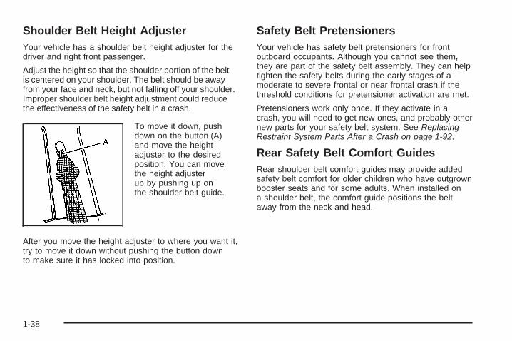
Shoulder Belt Height AdjusterYour vehicle has a shoulder belt height adjuster for thedriver and right front passenger.
Adjust the height so that the shoulder portion of the beltis centered on your shoulder. The belt should be awayfrom your face and neck, but not falling off your shoulder.Improper shoulder belt height adjustment could reducethe effectiveness of the safety belt in a crash.
To move it down, pushdown on the button (A)and move the heightadjuster to the desiredposition. You can movethe height adjusterup by pushing up onthe shoulder belt guide.
After you move the height adjuster to where you want it,try to move it down without pushing the button downto make sure it has locked into position.
Safety Belt PretensionersYour vehicle has safety belt pretensioners for frontoutboard occupants. Although you cannot see them,they are part of the safety belt assembly. They can helptighten the safety belts during the early stages of amoderate to severe frontal or near frontal crash if thethreshold conditions for pretensioner activation are met.
Pretensioners work only once. If they activate in acrash, you will need to get new ones, and probably othernew parts for your safety belt system. See ReplacingRestraint System Parts After a Crash on page 1-92.
Rear Safety Belt Comfort GuidesRear shoulder belt comfort guides may provide addedsafety belt comfort for older children who have outgrownbooster seats and for some adults. When installed ona shoulder belt, the comfort guide positions the beltaway from the neck and head.
1-38

There is one guide for each second row passengerposition. If your vehicle has a third row, there isone guide for each outboard position. Here is howto install a comfort guide to the shoulder belt:
1. Remove the guide from its storage pocket onthe side of the seatback.
2. Place the guide over the belt and insert thetwo edges of the belt into the slots of the guide.
1-39

3. Be sure that the belt is not twisted and it lies flat.The elastic cord must be under the belt and theguide on top.
{CAUTION:
A safety belt that is not properly worn maynot provide the protection needed in a crash.The person wearing the belt could be seriouslyinjured. The shoulder belt should go over theshoulder and across the chest. These parts ofthe body are best able to take belt restrainingforces.
1-40

4. Buckle, position, and release the safety belt asdescribed in previously in this section. Makesure that the shoulder belt crosses the shoulder.
To remove and store the comfort guide, squeeze thebelt edges together so that you can take them out ofthe guide. Slide the guide into the storage pocket.
Safety Belt Use During PregnancySafety belts work for everyone, including pregnantwomen. Like all occupants, they are more likely to beseriously injured if they do not wear safety belts.
A pregnant woman should wear a lap-shoulder belt,and the lap portion should be worn as low as possible,below the rounding, throughout the pregnancy.
The best way to protect the fetus is to protect themother. When a safety belt is worn properly, it is morelikely that the fetus will not be hurt in a crash. Forpregnant women, as for anyone, the key to makingsafety belts effective is wearing them properly.
1-41

Safety Belt ExtenderIf the vehicle’s safety belt will fasten around you,you should use it.
But if a safety belt is not long enough, yourdealer/retailer will order you an extender. When yougo in to order it, take the heaviest coat you willwear, so the extender will be long enough for you.To help avoid personal injury, do not let someone elseuse it, and use it only for the seat it is made to fit.The extender has been designed for adults. Neveruse it for securing child seats. To wear it, attach it tothe regular safety belt. For more information, seethe instruction sheet that comes with the extender.
Child Restraints
Older Children
Older children who have outgrown booster seats shouldwear the vehicle’s safety belts.
1-42

The manufacturer’s instructions that come with thebooster seat, state the weight and height limitations forthat booster. Use a booster seat with a lap-shoulderbelt until the child passes the below fit test:
• Sit all the way back on the seat. Do the knees bendat the seat edge? If yes, continue. If no, return tothe booster seat.
• Buckle the lap-shoulder belt. Does the shoulder beltrest on the shoulder? If yes, continue. If no, tryusing the rear safety belt comfort guide. See “RearSafety Belt Comfort Guides” under Lap-ShoulderBelt on page 1-36 for more information. If theshoulder belt still does not rest on the shoulder,then return to the booster seat.
• Does the lap belt fit low and snug on the hips,touching the thighs? If yes, continue. If no, returnto the booster seat.
• Can proper safety belt fit be maintained for thelength of the trip? If yes, continue. If no, returnto the booster seat.
Q: What is the proper way to wear safety belts?
A: An older child should wear a lap-shoulder belt andget the additional restraint a shoulder belt canprovide. The shoulder belt should not cross the faceor neck. The lap belt should fit snugly below thehips, just touching the top of the thighs. This appliesbelt force to the child’s pelvic bones in a crash.It should never be worn over the abdomen, whichcould cause severe or even fatal internal injuriesin a crash.
Also see “Rear Safety Belt Comfort Guides” underLap-Shoulder Belt on page 1-36.
According to accident statistics, children and infantsare safer when properly restrained in the rear seatingpositions than in the front seating positions.
In a crash, children who are not buckled up can strikeother people who are buckled up, or can be thrownout of the vehicle. Older children need to use safetybelts properly.
1-43

{CAUTION:
Never do this.
Here two children are wearing the same belt.The belt cannot properly spread the impactforces. In a crash, the two children can becrushed together and seriously injured. A beltmust be used by only one person at a time.
1-44

{CAUTION:
Never do this.
Here a child is sitting in a seat that has alap-shoulder belt, but the shoulder part isbehind the child. In a crash, the child wouldnot be restrained by the shoulder belt. Thechild might slide under the lap belt. The beltforce would then be applied right on theabdomen. That could cause serious or fatalinjuries. The child could also move too farforward increasing the chance of head andneck injury. The shoulder belt should goover the shoulder and across the chest.
1-45

Infants and Young ChildrenEveryone in a vehicle needs protection! This includesinfants and all other children. Neither the distancetraveled nor the age and size of the traveler changesthe need, for everyone, to use safety restraints. In fact,the law in every state in the United States and inevery Canadian province says children up to some agemust be restrained while in a vehicle.
{CAUTION:
Children can be seriously injured or strangledif a shoulder belt is wrapped around theirneck and the safety belt continues to tighten.Never leave children unattended in a vehicleand never allow children to play with thesafety belts.
Every time infants and young children ride in vehicles,they should have the protection provided by appropriaterestraints. Children who are not restrained properly canstrike other people, or can be thrown out of the vehicle.In addition, young children should not use the vehicle’sadult safety belts alone; they need to use a child restraint.
{CAUTION:
People should never hold a baby in their armswhile riding in a vehicle. A baby does not weighmuch — until a crash. During a crash a baby willbecome so heavy it is not possible to hold it.For example, in a crash at only 25mph(40km/h),a 12 lb (5.5 kg) baby will suddenly become a240 lb (110 kg) force on a person’s arms. A babyshould be secured in an appropriate restraint.
1-46

{CAUTION:
Children who are up against, or very close to,any airbag when it inflates can be seriouslyinjured or killed. Airbags plus lap-shoulderbelts offer protection for adults and olderchildren, but not for young children andinfants. Neither the vehicle’s safety belt systemnor its airbag system is designed for them.Young children and infants need the protectionthat a child restraint system can provide.
1-47

Q: What are the different types of add-on childrestraints?
A: Add-on child restraints, which are purchased by thevehicle’s owner, are available in four basic types.Selection of a particular restraint should takeinto consideration not only the child’s weight, height,and age but also whether or not the restraint willbe compatible with the motor vehicle in which itwill be used.
For most basic types of child restraints, there aremany different models available. When purchasinga child restraint, be sure it is designed to beused in a motor vehicle. If it is, the restraint willhave a label saying that it meets federal motorvehicle safety standards.
The restraint manufacturer’s instructions that comewith the restraint state the weight and heightlimitations for a particular child restraint. In addition,there are many kinds of restraints available forchildren with special needs.
{CAUTION:
Newborn infants need complete support,including support for the head and neck.This is necessary because a newborn infant’sneck is weak and its head weighs so muchcompared with the rest of its body. In a crash,an infant in a rear-facing seat settles intothe restraint, so the crash forces can bedistributed across the strongest part of aninfant’s body, the back and shoulders. Infantsshould always be secured in appropriateinfant restraints.
1-48

{CAUTION:
The body structure of a young child is quiteunlike that of an adult or older child, for whomthe safety belts are designed. A young child’ship bones are still so small that the vehicle’sregular safety belt may not remain low on thehip bones, as it should. Instead, it may settleup around the child’s abdomen. In a crash,the belt would apply force on a body area thatis unprotected by any bony structure. Thisalone could cause serious or fatal injuries.Young children should always be secured inappropriate child restraints.
Child Restraint Systems
A rear-facing infantseat (A) provides restraintwith the seating surfaceagainst the back ofthe infant.
The harness system holds the infant in place and, in acrash, acts to keep the infant positioned in the restraint.
A forward-facing childseat (B) provides restraintfor the child’s bodywith the harness.
1-49

A booster seat (C-D) is a child restraint designed toimprove the fit of the vehicle’s safety belt system.A booster seat can also help a child to see outthe window.
Securing an Add-On Child Restraint inthe Vehicle
{CAUTION:
A child can be seriously injured or killed ina crash if the child restraint is not properlysecured in the vehicle. Make sure the childrestraint is properly installed in the vehicleusing the vehicle’s safety belt or LATCHsystem, following the instructions that camewith that restraint, and also the instructionsin this manual.
1-50

To help reduce the chance of injury, the child restraintmust be secured in the vehicle. Child restraint systemsmust be secured in vehicle seats by lap belts or thelap belt portion of a lap-shoulder belt, or by the LATCHsystem. See Lower Anchors and Tethers for Children(LATCH) on page 1-53 for more information. A childcan be endangered in a crash if the child restraint isnot properly secured in the vehicle.
When securing an add-on child restraint, refer to theinstructions that come with the restraint which may beon the restraint itself or in a booklet, or both, and to thismanual. The child restraint instructions are important,so if they are not available, obtain a replacementcopy from the manufacturer.
Keep in mind that an unsecured child restraint canmove around in a collision or sudden stop and injurepeople in the vehicle. Be sure to properly secureany child restraint in your vehicle — even when nochild is in it.
Securing the Child Within theChild Restraint
{CAUTION:
A child can be seriously injured or killedin a crash if the child is not properly securedin the child restraint. Because there aredifferent systems, it is important to refer tothe instructions that come with the restraint.Make sure the child is properly secured,following the instructions that came withthat restraint.
1-51

Where to Put the RestraintAccident statistics show that children are safer if theyare restrained in the rear rather than the front seat.
We recommend that children and child restraintsbe secured in a rear seat, including: an infant or a childriding in a rear-facing child restraint; a child riding ina forward-facing child seat; an older child riding ina booster seat; and children, who are large enough,using safety belts.
A label on your sun visor says, “Never put a rear-facingchild seat in the front.” This is because the risk to therear-facing child is so great, if the airbag deploys.
{CAUTION:
A child in a rear-facing child restraint can beseriously injured or killed if the right frontpassenger’s airbag inflates. This is becausethe back of the rear-facing child restraintwould be very close to the inflating airbag.
Even though the passenger sensing system isdesigned to turn off the right front passenger’sfrontal airbag if the system detects a rear-facingchild restraint, no system is fail-safe, andno one can guarantee that an airbag will notdeploy under some unusual circumstance,even though it is turned off. We recommendthat rear-facing child restraints be secured in arear seat, even if the airbag is off.
If you secure a forward-facing child restraint inthe right front seat, always move the frontpassenger seat as far back as it will go. It isbetter to secure the child restraint in a rear seat.
See Passenger Sensing System on page 1-85for additional information.
1-52

If your vehicle does not have a rear seat that willaccommodate a rear-facing child restraint, werecommend that rear-facing child restraints not betransported in your vehicle, even if the airbag is off.
When securing a child restraint in a rear seatingposition, study the instructions that came withyour child restraint to make sure it is compatiblewith this vehicle.
Wherever you install a child restraint, be sure tosecure the child restraint properly.
Keep in mind that an unsecured child restraint canmove around in a collision or sudden stop and injurepeople in the vehicle. Be sure to properly secureany child restraint in your vehicle — even whenno child is in it.
Lower Anchors and Tethers forChildren (LATCH)The LATCH system holds a child restraint duringdriving or in a crash. This system is designed to makeinstallation of a child restraint easier. The LATCHsystem uses anchors in the vehicle and attachmentson the child restraint that are made for use withthe LATCH system.
Make sure that a LATCH-compatible child restraintis properly installed using the anchors, or use thevehicle’s safety belts to secure the restraint, followingthe instructions that came with that restraint, andalso the instructions in this manual. When installinga child restraint with a top tether, you must alsouse either the lower anchors or the safety belts toproperly secure the child restraint. A child restraintmust never be installed using only the top tetherand anchor.
1-53

In order to use the LATCH system in your vehicle, youneed a child restraint that has LATCH attachments.The child restraint manufacturer will provide youwith instructions on how to use the child restraint and itsattachments. The following explains how to attach achild restraint with these attachments in your vehicle.
Not all vehicle seating positions or child restraints havelower anchors and attachments or top tether anchorsand attachments.
Lower Anchors
Lower anchors (A) are metal bars built into the vehicle.There are two lower anchors for each LATCH seatingposition that will accommodate a child restraint withlower attachments (B).
1-54

Top Tether Anchor
A top tether (A, C) anchors the top of the child restraintto the vehicle. A top tether anchor is built into thevehicle. The top tether attachment (B) on the childrestraint connects to the top tether anchor in the vehiclein order to reduce the forward movement and rotationof the child restraint during driving or in a crash.
Your child restraint may have a single tether (A) or adual tether (C). Either will have a single attachment (B)to secure the top tether to the anchor.
Some child restraints that have a top tether are designedfor use with or without the top tether being attached.Others require the top tether always to be attached.In Canada, the law requires that forward-facingchild restraints have a top tether, and that the tether beattached. Be sure to read and follow the instructionsfor your child restraint.
If the child restraint does not have a top tether, one canbe obtained, in kit form, for many child restraints.Ask the child restraint manufacturer whether or not akit is available.
1-55

Lower Anchor and Top Tether AnchorLocations
i (Top Tether Anchor):Seating positions withtop tether anchors.
j (Lower Anchor):Seating positions withtwo lower anchors.
i (Top Tether Anchor):Seating positions withtop tether anchors.
To assist you in locatingthe lower anchors, eachseating position with loweranchors has two labels,near the crease betweenthe seatback and theseat cushion.
For the second row seating positions, the top tetheranchors are located on the seatback, near the base ofeach seat. Be sure to use an anchor located on thesame side of the vehicle as the seating position wherethe child restraint will be placed.
Second Row
Third Row
1-56

For the center third row position, if your vehicle hasone, the top tether anchor is located on the seatback,near the center of the third row seating position.This anchor can accommodate only one top tether.
Do not secure a child restraint in a position without atop tether anchor if a national or local law requires thatthe top tether be attached, or if the instructions thatcome with the child restraint say that the top tethermust be attached.
Accident statistics show that children are safer if theyare restrained in the rear rather than the front seat.See Where to Put the Restraint on page 1-52 foradditional information.
Second Row
Third Row
1-57

Securing a Child Restraint Designed forthe LATCH System
{CAUTION:
If a LATCH-type child restraint is not attached toanchors, the restraint will not be able to protectthe child correctly. In a crash, the child couldbe seriously injured or killed. Make sure that aLATCH-type child restraint is properly installedusing the anchors, or use the vehicle’s safetybelts to secure the restraint, following theinstructions that came with that restraint,and also the instructions in this manual.
{CAUTION:
Each top tether anchor and lower anchor inthe vehicle is designed to hold only one childrestraint. Attaching more than one childrestraint to a single anchor could cause theanchor or attachment to come loose or evenbreak during a crash. A child or others couldbe injured if this happens. To help preventinjury to people and damage to your vehicle,attach only one child restraint per anchor.
1-58

{CAUTION:
Children can be seriously injured or strangledif a shoulder belt is wrapped around theirneck and the safety belt continues to tighten.Secure any unused safety belts behind thechild restraint so children cannot reach them.Pull the shoulder belt all the way out of theretractor to set the lock, if your vehicle hasone, after the child restraint has been installed.Be sure to follow the instructions of the childrestraint manufacturer.
Notice: Contact between the child restraint LATCHattachment parts and the vehicle’s safety beltassembly may cause damage to these parts. Makesure when securing unused safety belts behindthe child restraint that there is no contact betweenthe child restraint LATCH attachment parts andthe vehicle’s safety belt assembly.
Folding an empty rear seat with the safety beltssecured may cause damage to the safety belt or theseat. When removing the child restraint, alwaysremember to return the safety belts to their normal,stowed position before folding the rear seat.
1. Attach and tighten the lower attachments to thelower anchors. If the child restraint does not havelower attachments or the desired seating positiondoes not have lower anchors, secure the childrestraint with the top tether and the safety belts.Refer to your child restraint manufacturerinstructions and the instructions in this manual.
1.1. Find the lower anchors for the desiredseating position.
1.2. Put the child restraint on the seat.1.3. Attach and tighten the lower attachments on
the child restraint to the lower anchors.
1-59

2. If the child restraint manufacturer recommends thatthe top tether be attached, attach and tighten thetop tether to the top tether anchor, if equipped.Refer to the child restraint instructions andthe following steps:
2.1. Find the top tether anchor.2.2. Route, attach, and tighten the top tether
according to your child restraint instructionsand the following instructions:
If the position you areusing does not have aheadrest or head restraintand you are using asingle tether, route thetether over the seatback.
If the position you areusing does not have aheadrest or head restraintand you are using adual tether, route the tetherover the seatback.
If the position you areusing has an adjustableheadrest or head restraintand you are using adual tether, route the tetheraround the headrest orhead restraint.
1-60

If the position you areusing has an adjustableheadrest or head restraintand you are using asingle tether, raise theheadrest or head restraintand route the tetherunder the headrest orhead restraint andin between the headrestor head restraint posts.
3. Push and pull the child restraint in differentdirections to be sure it is secure.
Securing a Child Restraint in aRear Seat PositionWhen securing a child restraint in a rear seatingposition, study the instructions that came with your childrestraint to make sure it is compatible with this vehicle.
If your child restraint has the LATCH system, see LowerAnchors and Tethers for Children (LATCH) on page 1-53for how to install your child restraint using LATCH. If yousecure a child restraint using a safety belt and it uses atop tether, see Lower Anchors and Tethers for Children(LATCH) on page 1-53 for top tether anchor locations.
Do not secure a child seat in a position without a toptether anchor if a national or local law requires thatthe top tether be anchored, or if the instructionsthat come with the child restraint say that the top strapmust be anchored.
In Canada, the law requires that forward-facing childrestraints have a top tether, and that the tether beattached.
If your child restraint does not have the LATCH system,you will be using the safety belt to secure the childrestraint in this position. Be sure to follow the instructionsthat came with the child restraint. Secure the child inthe child restraint when and as the instructions say.
1-61

If you need to install more than one child restraint in therear seat, be sure to read Where to Put the Restrainton page 1-52.
1. Put the child restraint on the seat.
2. Pick up the latch plate, and run the lap and shoulderportions of the vehicle’s safety belt through oraround the restraint. The child restraint instructionswill show you how.
3. Push the latch plate into the buckle until it clicks.Make sure the release button is positioned so youwould be able to unbuckle the safety belt quicklyif necessary.
4. Pull the rest of the shoulder belt all the way out ofthe retractor to set the lock.
1-62
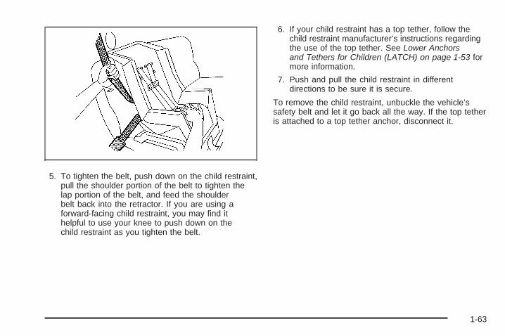
5. To tighten the belt, push down on the child restraint,pull the shoulder portion of the belt to tighten thelap portion of the belt, and feed the shoulderbelt back into the retractor. If you are using aforward-facing child restraint, you may find ithelpful to use your knee to push down on thechild restraint as you tighten the belt.
6. If your child restraint has a top tether, follow thechild restraint manufacturer’s instructions regardingthe use of the top tether. See Lower Anchorsand Tethers for Children (LATCH) on page 1-53 formore information.
7. Push and pull the child restraint in differentdirections to be sure it is secure.
To remove the child restraint, unbuckle the vehicle’ssafety belt and let it go back all the way. If the top tetheris attached to a top tether anchor, disconnect it.
1-63

Securing a Child Restraint in theRight Front Seat PositionYour vehicle has airbags. A rear seat is a safer placeto secure a forward-facing child restraint. See Whereto Put the Restraint on page 1-52.
In addition, your vehicle has a passenger sensingsystem which is designed to turn off the right frontpassenger’s frontal airbag and seat-mounted sideimpact airbag (if equipped) under certain conditions.See Passenger Sensing System on page 1-85 andPassenger Airbag Status Indicator on page 3-38for more information on this, including importantsafety information.
A label on your sun visor says, “Never put a rear-facingchild seat in the front.” This is because the risk to therear-facing child is so great, if the airbag deploys.
{CAUTION:
A child in a rear-facing child restraint can beseriously injured or killed if the right frontpassenger’s airbag inflates. This is becausethe back of the rear-facing child restraintwould be very close to the inflating airbag.
Even though the passenger sensing system isdesigned to turn off the right front passenger’sfrontal airbag if the system detects a rear-facingchild restraint, no system is fail-safe, andno one can guarantee that an airbag will notdeploy under some unusual circumstance,even though it is turned off. We recommendthat rear-facing child restraints be secured ina rear seat, even if the airbag is off.
If you secure a forward-facing child restraint inthe right front seat, always move the frontpassenger seat as far back as it will go. It isbetter to secure the child restraint in a rear seat.
See Passenger Sensing System on page 1-85for additional information.
1-64

If your vehicle does not have a rear seat that willaccommodate a rear-facing child restraint, werecommend that rear-facing child restraints not betransported in your vehicle, even if the airbag is off.
If your child restraint has the LATCH system, see LowerAnchors and Tethers for Children (LATCH) on page 1-53for how to install your child restraint using LATCH. If yousecure a child restraint using a safety belt and it uses atop tether, see Lower Anchors and Tethers for Children(LATCH) on page 1-53 for top tether anchor locations.
Do not secure a child seat in a position without a toptether anchor if a national or local law requires thatthe top tether be anchored, or if the instructionsthat come with the child restraint say that the topstrap must be anchored.
In Canada, the law requires that forward-facing childrestraints have a top tether, and that the tether beattached.
You will be using the lap-shoulder belt to secure thechild restraint in this position. Follow the instructions thatcame with the child restraint.
1. Move the seat as far back as it will go beforesecuring the forward-facing child restraint.When the passenger sensing system has turnedoff the right front passenger’s frontal airbagand seat-mounted side impact airbag (if equipped),the off indicator on the passenger airbag statusindicator should light and stay lit when you start thevehicle. See Passenger Airbag Status Indicatoron page 3-38.
2. Put the child restraint on the seat.
3. Pick up the latch plate, and run the lap and shoulderportions of the vehicle’s safety belt through oraround the restraint. The child restraint instructionswill show you how.
1-65

4. Push the latch plate into the buckle until it clicks.Make sure the release button is positioned so youwould be able to unbuckle the safety belt quicklyif necessary.
5. Pull the rest of the shoulder belt all the way out ofthe retractor to set the lock.
1-66

6. To tighten the belt, push down on the child restraint,pull the shoulder portion of the belt to tighten thelap portion of the belt and feed the shoulderbelt back into the retractor. If you are using aforward-facing child restraint, you may find ithelpful to use your knee to push down on thechild restraint as you tighten the belt.
7. If your vehicle does not have a rear seat and yourchild restraint has a top tether, follow the childrestraint manufacturer’s instructions regarding theuse of the top tether. See Lower Anchors andTethers for Children (LATCH) on page 1-53 formore information.
8. Push and pull the child restraint in differentdirections to be sure it is secure.
If the airbag or airbags are off, the off indicator in thepassenger airbag status indicator will come on andstay on when the vehicle is started.
If a child restraint has been installed and on indicatoris lit, turn the vehicle off. Remove the child restraintfrom the vehicle and reinstall the child restraint.
If, after reinstalling the child restraint and restarting thevehicle, the on indicator is still lit, is still not lit, checkto make sure that the vehicle’s seatback is not pressingthe child restraint into the seat cushion. If this happens,slightly recline the vehicle’s seatback and adjust theseat cushion if possible. Also make sure the childrestraint is not trapped under the vehicle head restraint.If this happens, adjust the head restraint.
Remove any additional material from the seat suchas blankets, cushions, seat covers, seat heaters orseat massagers before reinstalling or securing thechild restraint.
If the off symbol is still not lit, secure the child in thechild restraint in a rear seat position in the vehicle,if one is available, and check with your dealer/retailer.
To remove the child restraint, unbuckle the vehicle’ssafety belt and let it go back all the way. If the toptether is attached to a top tether anchor, disconnect it.
1-67

Built-In Child Restraint
WARNING! DEATH or SERIOUS INJURYcan occur:• Follow all instruction on the child restraint and in
the vehicle’s owner’s manual.
If your vehicle has this feature, the built-in childrestraint is located in the passenger-side positionin the second row.
This child restraint system conforms to all applicableFederal Motor Vehicle Safety Standards.
Use only with children who weigh between 22 and40 lbs (10 and 18 kg) and whose height is between33.5 and 40 in (850 and 1 016 mm). Use only withchildren whose shoulders are below the shoulderbelt slots for the harness system and who arecapable of sitting upright alone.The child should also be at least one year old. It isimportant to use a rear-facing infant restraint until thechild is at least one year old. A rear-facing restraint givesthe infant’s head, neck and body the support theywould need in a crash. See Older Children on page 1-42or Infants and Young Children on page 1-46.
A child whose weight is over 40 lbs (18 kg), whoseheight is over 40 in (1 016 mm) or whose shoulders areabove the shoulder belt slots for the harness system,should be restrained in an add-on booster seatappropriate for the child’s size. See Child RestraintSystems on page 1-49. Once the booster seat isoutgrown, the child should sit on the vehicle’s regularseat and use the vehicle’s safety belts.
1-68

{CAUTION:
Using the vehicle’s built-in child restraint as abooster seat for a larger child could causeinjury to the child in a sudden stop or crash.A child whose weight is over 40 lbs (18 kg),whose height is over 40 in (1 016 mm) orwhose shoulders are above the shoulder beltslots for the harness system should use arestraint system that is appropriate for theirsize, either an add-on booster seat or thevehicle’s safety belt. See Child RestraintSystems on page 1-49 or Older Childrenon page 1-42.
Securing a Child in the Built-In ChildRestraint
1. Raise the head restraint until the lower edge of thehead restraint is even with the top of the seatback.
1-69

2. Rotate the head restraint rearward until it touchesthe top of the seatback. Make sure there is no gapbetween the lower edge of the head restraintand the top of the seatback.
3. Lower the child restraint cushion.
1-70

You will be using the child restraint’s harness (A)to secure your child. Do not use the vehicle’ssafety belts.
{CAUTION:
Using the vehicle’s regular safety belts on achild seated on the built-in child restraintcushion can cause serious injury to the childin a sudden stop or crash. Secure the childusing the built-in child restraint’s harness.
WARNING: FAILURE TO FOLLOW THEMANUFACTURER’S INSTRUCTIONS ON THEUSE OF THIS CHILD RESTRAINT SYSTEMCAN RESULT IN YOUR CHILD STRIKING THEVEHICLE’S INTERIOR DURING A SUDDENSTOP OR CRASH.SNUGLY ADJUST THE BELTS PROVIDED WITHTHIS CHILD RESTRAINT AROUND YOUR CHILD.
4. Before placing the child in the child restraint,add slack to the shoulder harness. Pull theblack shoulder harness release strap firmly.At the same time pull both shoulder harnessstraps through the slots in the seatback as shown.
1-71

5. Place the child on the child restraint cushion.
6. Select only one side of the harness. Place theharness over the child’s shoulder.
7. Push the latch plate (A) into the buckle until it clicks.Be sure the buckle is free of any foreign objectsthat may prevent you from securing the latch plates.If you can not secure a latch plate, see your dealer/retailer for service before using the child restraint.
8. Place the other side of the harness over thechild’s shoulder.
9. Push the latch plate into the buckle until it clicks.
10. Pull up on the latch plates to make sure theyare secure.
1-72
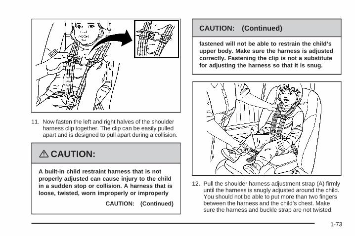
11. Now fasten the left and right halves of the shoulderharness clip together. The clip can be easily pulledapart and is designed to pull apart during a collision.
{CAUTION:
A built-in child restraint harness that is notproperly adjusted can cause injury to the childin a sudden stop or collision. A harness that isloose, twisted, worn improperly or improperly
CAUTION: (Continued)
CAUTION: (Continued)
fastened will not be able to restrain the child’supper body. Make sure the harness is adjustedcorrectly. Fastening the clip is not a substitutefor adjusting the harness so that it is snug.
12. Pull the shoulder harness adjustment strap (A) firmlyuntil the harness is snugly adjusted around the child.You should not be able to put more than two fingersbetween the harness and the child’s chest. Makesure the harness and buckle strap are not twisted.
1-73

13. Adjust the position of the harness on the child’sshoulder by moving the clip along the harness until itis level with the child’s armpits. On each side of theharness, the shoulder part should be centered on thechild’s shoulder. The harness should be away fromthe child’s face and neck, but not falling from thechild’s shoulders.If you expect that the child will sleep while riding,you can recline the seatback. See Bucket Seatson page 1-6.
Removing the Child from the Built-InChild Restraint
1. Unfasten the shoulder harness clip.
1-74

2. Unlatch the harness by pushing the button onthe buckle.
3. Move one side of the harness off the child’sshoulder.
4. Move the other side of the harness off thechild’s shoulder.
5. Remove the child from the child restraint cushion.
Storing the Built-In Child RestraintAlways properly store the built-in child restraint beforeusing the vehicle’s lap-shoulder belt.
1. Move both latch plates and both sides of theshoulder harness clip to the bottom of theharness straps.
1-75

2. Fold the child restraint cushion and leg rest upinto the seatback.
3. Press the child restraint cushion firmly into theseatback.
4. Then press the leg rest firmly into the seatback,and secure it by pressing the upper cornersagainst the fastener strips on the seatback.
1-76

5. Rotate the head restraint forward and push it allthe way down.
Just like the other restraint systems in your vehicle,your built-in child restraint needs to be periodicallychecked and may need to have parts replaced aftera crash. See Checking the Restraint Systems onpage 1-91 and Replacing Restraint System PartsAfter a Crash on page 1-92.
Airbag SystemYour vehicle has the following airbags:
• A frontal airbag for the driver.
• A frontal airbag for the right front passenger.
Your vehicle may have the following airbags:
• A seat-mounted side impact airbag for the driver.
• A seat-mounted side impact airbag for the rightfront passenger.
• Seat-mounted side impact airbags are available forthe second row captain’s chairs (if equipped).
For frontal airbags, the word AIRBAG will appear on themiddle part of the steering wheel for the driver andon the instrument panel for the right front passenger.
With seat-mounted side impact airbags, the wordAIRBAG will appear on the side of the seatback closestto the door.
1-77

Airbags are designed to supplement the protectionprovided by safety belts. Even though today’s airbagsare also designed to help reduce the risk of injuryfrom the force of an inflating bag, all airbags mustinflate very quickly to do their job.
Here are the most important things to know about theairbag system:
{CAUTION:
You can be severely injured or killed in a crashif you are not wearing your safety belt — evenif you have airbags. Wearing your safety beltduring a crash helps reduce your chance ofhitting things inside the vehicle or beingejected from it. Airbags are “supplementalrestraints” to the safety belts. All airbags aredesigned to work with safety belts, but do notreplace them.
{CAUTION:
Frontal airbags are designed to deploy inmoderate to severe frontal and near frontalcrashes. They are not designed to inflate inrollover, rear crashes, or in many side crashes.
Seat-mounted side impact airbags aredesigned to inflate in moderate to severecrashes where something hits the side of yourvehicle. They are not designed to inflate infrontal, in rollover, or in rear crashes.
Everyone in your vehicle should wear a safetybelt properly — whether or not there is anairbag for that person.
1-78

{CAUTION:
Airbags inflate with great force, faster thanthe blink of an eye. Anyone who is up against,or very close to, any airbag when it inflatescan be seriously injured or killed. Do not situnnecessarily close to the airbag, as youwould be if you were sitting on the edge ofyour seat or leaning forward. Safety beltshelp keep you in position before and duringa crash. Always wear your safety belt, evenwith airbags. The driver should sit as far backas possible while still maintaining control ofthe vehicle.
Occupants should not lean on or sleep againstthe door or side windows in seating positionswith seat-mounted airbags.
{CAUTION:
Airbags plus lap-shoulder belts offer thebest protection for adults, but not for youngchildren and infants. Neither the vehicle’ssafety belt system nor its airbag system isdesigned for them. Young children and infantsneed the protection that a child restraintsystem can provide. Always secure childrenproperly in your vehicle. To read how, seeOlder Children on page 1-42 or Infants andYoung Children on page 1-46.
There is an airbagreadiness light onthe instrument panelcluster, which showsthe airbag symbol.
The system checks the airbag electrical system formalfunctions. The light tells you if there is an electricalproblem. See Airbag Readiness Light on page 3-37for more information.
1-79

Where Are the Airbags?
The driver’s frontal airbag is in the middle of thesteering wheel.
The right front passenger’s frontal airbag is in theinstrument panel on the passenger’s side.
1-80

If your vehicle has seat-mounted side impact airbagsfor the driver and right front passenger, they are in theside of the seatbacks closest to the door.
If your vehicle has second row captain’s chairs, theseat-mounted side impact airbags (if equipped) are inthe side of the seatback closest to the door.
{CAUTION:
If something is between an occupant and anairbag, the airbag might not inflate properlyor it might force the object into that personcausing severe injury or even death. The pathof an inflating airbag must be kept clear.Do not put anything between an occupant andan airbag, and do not attach or put anythingon the steering wheel hub or on or near anyother airbag covering.
Do not use seat accessories that block theinflation path of a seat-mounted side impactairbag.
Driver Side shown, Passenger Side similar
1-81

When Should an Airbag Inflate?Frontal airbags are designed to inflate in moderate tosevere frontal or near-frontal crashes to help reduce thepotential for severe injuries mainly to the driver’s orright front passenger’s head and chest. However, theyare only designed to inflate if the impact exceeds apredetermined deployment threshold. Deploymentthresholds are used to predict how severe a crash islikely to be in time for the airbags to inflate andhelp restrain the occupants.
Whether your frontal airbags will or should deploy is notbased on how fast your vehicle is traveling. It dependslargely on what you hit, the direction of the impact,and how quickly your vehicle slows down.
Frontal airbags may inflate at different crash speeds.For example:
• If the vehicle hits a stationary object, the airbagscould inflate at a different crash speed than if thevehicle hits a moving object.
• If the vehicle hits an object that deforms, theairbags could inflate at a different crash speed thanif the vehicle hits an object that does not deform.
• If the vehicle hits a narrow object (like a pole), theairbags could inflate at a different crash speedthan if the vehicle hits a wide object (like a wall).
• If the vehicle goes into an object at an angle, theairbags could inflate at a different crash speedthan if the vehicle goes straight into the object.
Thresholds can also vary with specific vehicle design.
In addition, your vehicle has dual-stage frontal airbags.Dual-stage airbags adjust the restraint according tocrash severity. Your vehicle has electronic frontalsensors, which help the sensing system distinguishbetween a moderate frontal impact and a more severefrontal impact. For moderate frontal impacts, dual-stageairbags inflate at a level less than full deployment.For more severe frontal impacts, full deployment occurs.
Frontal airbags are not intended to inflate duringvehicle rollovers, rear impacts, or in many side impacts.
Your vehicle may or may not have seat-mounted sideimpact airbags. See Airbag System on page 1-77.Seat-mounted side impact airbags are intended to inflatein moderate to severe side crashes. Seat-mounted sideimpact airbags will inflate if the crash severity is abovethe system’s designed threshold level. The thresholdlevel can vary with specific vehicle design.
Seat-mounted side impact airbags are not intended toinflate in frontal impacts, near-frontal impacts, rollovers,or rear impacts. A seat-mounted side impact airbagis intended to deploy on the side of the vehicle thatis struck.
1-82

In any particular crash, no one can say whether anairbag should have inflated simply because of thedamage to a vehicle or because of what the repair costswere. For frontal airbags, inflation is determined bywhat the vehicle hits, the angle of the impact, and howquickly the vehicle slows down. For seat-mountedside impact airbags, deployment is determined by thelocation and severity of the side impact.
What Makes an Airbag Inflate?In a deployment event, the sensing system sendsan electrical signal triggering a release of gas fromthe inflator. Gas from the inflator fills the airbagcausing the bag to break out of the cover and deploy.The inflator, the airbag, and related hardware areall part of the airbag module.
Frontal airbag modules are located inside the steeringwheel and instrument panel. For vehicles withseat-mounted side impact airbags, there are airbagmodules in the side of the front seatbacks closestto the door.
How Does an Airbag Restrain?In moderate to severe frontal or near frontal collisions,even belted occupants can contact the steering wheelor the instrument panel. In moderate to severe sidecollisions, even belted occupants can contact the insideof the vehicle.
Airbags supplement the protection provided by safetybelts. Frontal airbags distribute the force of theimpact more evenly over the occupant’s upper body,stopping the occupant more gradually. Seat-mountedside impact airbags distribute the force of the impactmore evenly over the occupant’s upper body.
But airbags would not help in many types of collisions,primarily because the occupant’s motion is nottoward those airbags. See When Should an AirbagInflate? on page 1-82 for more information.
Airbags should never be regarded as anything morethan a supplement to safety belts.
1-83

What Will You See After anAirbag Inflates?After the frontal and seat-mounted side impact airbagsinflate, they quickly deflate, so quickly that somepeople may not even realize the airbags inflated.Some components of the airbag module may be hotfor several minutes. For location of the airbag modules,see What Makes an Airbag Inflate? on page 1-83.
The parts of the airbag that come into contact with youmay be warm, but not too hot to touch. There maybe some smoke and dust coming from the vents in thedeflated airbags. Airbag inflation does not preventthe driver from seeing out of the windshield or beingable to steer the vehicle, nor does it prevent peoplefrom leaving the vehicle.
{CAUTION:
When an airbag inflates, there may be dustin the air. This dust could cause breathingproblems for people with a history of asthmaor other breathing trouble. To avoid this,everyone in the vehicle should get out as soonas it is safe to do so. If you have breathingproblems but cannot get out of the vehicleafter an airbag inflates, then get fresh air byopening a window or a door. If you experiencebreathing problems following an airbagdeployment, you should seek medicalattention.
Your vehicle has a feature that may automaticallyunlock the doors, turn the interior lamps on, and turnon the hazard warning flashers when the airbags inflate.You can lock the doors, turn the interior lamps off,and turn the hazard warning flashers off by using thecontrols for those features.
1-84

In many crashes severe enough to inflate the airbag,windshields are broken by vehicle deformation.Additional windshield breakage may also occur fromthe right front passenger airbag.
• Airbags are designed to inflate only once. After anairbag inflates, you will need some new parts forthe airbag system. If you do not get them, the airbagsystem will not be there to help protect you inanother crash. A new system will include airbagmodules and possibly other parts. The servicemanual for your vehicle covers the need to replaceother parts.
• Your vehicle has a crash sensing and diagnosticmodule which records information after a crash.See Vehicle Data Recording and Privacy onpage 7-16 and Event Data Recorders on page 7-16.
• Let only qualified technicians work on the airbagsystem. Improper service can mean that theairbag system will not work properly. See yourdealer/retailer for service.
Passenger Sensing SystemYour vehicle has a passenger sensing system forthe right front passenger’s position. The passengerairbag status indicator will be visible on the instrumentpanel when you start your vehicle.
The words ON and OFF, or the symbol for on and off,will be visible during the system check. If you areusing remote start to start your vehicle from a distance,if equipped, you may not see the system check.When the system check is complete, either the wordON or the word OFF, or the symbol for on or the symbolfor off, will be visible. See Passenger Airbag StatusIndicator on page 3-38.
United States Canada
1-85

The passenger sensing system will turn off the rightfront passenger’s frontal airbag and seat-mounted sideimpact airbag (if equipped) under certain conditions.The driver’s airbags are not part of the passengersensing system.
The passenger sensing system works with sensors thatare part of the right front passenger’s seat and safetybelt. The sensors are designed to detect the presenceof a properly-seated occupant and determine if theright front passenger’s frontal airbag and seat-mountedside impact airbag (if equipped) should be enabled(may inflate) or not.
Accident statistics show that children are safer if theyare restrained in the rear rather than the front seat.
We recommend that children be secured in a rear seat,including: an infant or a child riding in a rear-facingchild restraint; a child riding in a forward-facing childseat; an older child riding in a booster seat; and children,who are large enough, using safety belts.
A label on your sun visor says, “Never put a rear-facingchild seat in the front.” This is because the risk to therear-facing child is so great, if the airbag deploys.
{CAUTION:
A child in a rear-facing child restraint can beseriously injured or killed if the right frontpassenger’s airbag inflates. This is becausethe back of the rear-facing child restraintwould be very close to the inflating airbag.
Even though the passenger sensing system isdesigned to turn off the right front passenger’sfrontal and seat-mounted side impact airbag(if equipped) if the system detects a rear-facingchild restraint, no system is fail-safe, andno one can guarantee that an airbag will notdeploy under some unusual circumstance,even though it is turned off. We recommendthat rear-facing child restraints be secured ina rear seat, even if the airbag(s) are off.
If you secure a forward-facing child restraint inthe right front seat, always move the frontpassenger seat as far back as it will go. It isbetter to secure the child restraint in a rear seat.
1-86

If your vehicle does not have a rear seat that willaccommodate a rear-facing child restraint, werecommend that rear-facing child restraints not betransported in your vehicle, even if the airbag(s) are off.
The passenger sensing system is designed to turnoff the right front passenger’s frontal airbag andseat-mounted side impact airbag (if equipped) if:• The right front passenger seat is unoccupied.• The system determines that an infant is present in
a rear-facing infant seat.• The system determines that a small child is present
in a child restraint.• The system determines that a small child is present
in a booster seat.• A right front passenger takes his/her weight off of
the seat for a period of time.• The right front passenger seat is occupied by a
smaller person, such as a child who has outgrownchild restraints.
• Or, if there is a critical problem with the airbagsystem or the passenger sensing system.
When the passenger sensing system has turned off theright front passenger’s frontal airbag and seat-mountedside impact airbag (if equipped), the off indicator will lightand stay lit to remind you that the airbag or airbags areoff. See Passenger Airbag Status Indicator on page 3-38.
If a child restraint has been installed and the onindicator is lit, turn the vehicle off. Remove the childrestraint from the vehicle and reinstall the child restraintfollowing the child restraint manufacturer’s directionsand refer to Securing a Child Restraint in the Right FrontSeat Position on page 1-64.
If, after reinstalling the child restraint and restartingthe vehicle, the on indicator is still lit, check to makesure that the vehicle’s seatback is not pressing the childrestraint into the seat cushion. If this happens, slightlyrecline the vehicle’s seatback and adjust the seatcushion if possible. Also make sure the child restraintis not trapped under the vehicle head restraint.If this happens, adjust the head restraint. See HeadRestraints on page 1-6.
Remove any additional material from the seat suchas blankets, cushions, seat covers, seat heaters,or seat massagers before reinstalling or securing thechild restraint.
If the on indicator is still lit, secure the child in the childrestraint in a rear seat position in the vehicle, andcheck with your dealer/retailer. If no rear seat isavailable, do not install a child restraint in this vehicle,and check with your dealer/retailer.
1-87

The passenger sensing system is designed to enable(may inflate) the right front passenger’s frontal airbag andseat-mounted side impact airbag (if equipped) anytimethe system senses that a person of adult size is sittingproperly in the right front passenger’s seat. When thepassenger sensing system has allowed the airbag orairbags to be enabled, the on indicator will light and staylit to remind you that the airbag or airbags are active.
For some children who have outgrown child restraintsand for very small adults, the passenger sensing systemmay or may not turn off the right front passenger’sfrontal airbag and seat-mounted side impact airbag(if equipped), depending upon the person’s seatingposture and body build. Everyone in your vehicle whohas outgrown child restraints should wear a safetybelt properly — whether or not there is an airbag forthat person.
If a person of adult-size is sitting in the right frontpassenger’s seat, but the off indicator is lit, it could bebecause that person is not sitting properly in the seat.If this happens, turn the vehicle off, remove any additionalmaterial from the seat, such as blankets, cushions,seat covers, seat heaters or seat massagers and askthe person to place the seatback in the fully uprightposition, then sit upright in the seat, centered on the seatcushion, with the person’s legs comfortably extended.
Restart the vehicle and have the person remain in thisposition for two to three minutes. This will allow thesystem to detect that person and then enable the rightfront passenger’s frontal airbag.
Safety belts help keep the passenger in position on theseat during vehicle maneuvers and braking, which helpsthe passenger sensing system maintain the passengerairbag status. See “Safety Belts” and “Child Restraints” inthe Index for additional information about the importanceof proper restraint use.
1-88

If you ever pull the shoulder portion of the belt out allthe way, you will engage the child restraint lockingfeature. This may unintentionally cause the passengersensing system to turn the airbag(s) off for someadult size occupants. If this happens, just let the beltgo back all the way and start again.
{CAUTION:
If the airbag readiness light in the instrumentpanel cluster ever comes on and stays on,it means that something may be wrong withthe airbag system. If this ever happens, havethe vehicle serviced promptly, because anadult-size person sitting in the right frontpassenger’s seat may not have the protectionof the airbag(s). See Airbag Readiness Lighton page 3-37 for more on this, includingimportant safety information.
A thick layer of additional material, such as a blanketor cushion, or aftermarket equipment such as seatcovers, seat heaters, and seat massagers can affecthow well the passenger sensing system operates.We recommend that you not use seat covers or otheraftermarket equipment other than any that GM hasapproved for your specific vehicle. See AddingEquipment to Your Airbag-Equipped Vehicle onpage 1-90 for more information about modificationsthat can affect how the system operates.
{CAUTION:
Stowing of articles under the passenger’sseat or between the passenger’s seat cushionand seatback may interfere with the properoperation of the passenger sensing system.
1-89
Servicing Your Airbag-EquippedVehicleAirbags affect how your vehicle should be serviced.There are parts of the airbag system in several placesaround your vehicle. Your dealer/retailer and the servicemanual have information about servicing your vehicle andthe airbag system. To purchase a service manual, seeService Publications Ordering Information on page 7-15.
{CAUTION:
For up to 10 seconds after the ignition isturned off and the battery is disconnected,an airbag can still inflate during improperservice. You can be injured if you are closeto an airbag when it inflates. Avoid yellowconnectors. They are probably part of theairbag system. Be sure to follow properservice procedures, and make sure the personperforming work for you is qualified to do so.
Adding Equipment to YourAirbag-Equipped Vehicle
Q: Is there anything I might add to or changeabout the vehicle that could keep the airbagsfrom working properly?
A: Yes. If you add things that change your vehicle’sframe, bumper system, height, front end or sidesheet metal, they may keep the airbag system fromworking properly. Changing or moving any partsof the front seats, safety belts, the airbag sensingand diagnostic module, steering wheel, instrumentpanel, front sensors, or airbag wiring can affectthe operation of the airbag system.
In addition, your vehicle has a passenger sensingsystem for the right front passenger’s position,which includes sensors that are part of thepassenger’s seat. The passenger sensing systemmay not operate properly if the original seattrim is replaced with non-GM covers, upholsteryor trim, or with GM covers, upholstery or trimdesigned for a different vehicle. Any object,such as an aftermarket seat heater or a comfortenhancing pad or device, installed under or ontop of the seat fabric, could also interfere withthe operation of the passenger sensing system.
1-90

This could either prevent proper deployment ofthe passenger airbag(s) or prevent the passengersensing system from properly turning off thepassenger airbag(s). See Passenger SensingSystem on page 1-85.
If you have any questions about this, you shouldcontact Customer Assistance before you modifyyour vehicle. The phone numbers and addressesfor Customer Assistance are in Step Two ofthe Customer Satisfaction Procedure in this manual.See Customer Satisfaction Procedure on page 7-2.
Q: Because I have a disability, I have to getmy vehicle modified. How can I find out whetherthis will affect my airbag system?
A: If you have questions, call Customer Assistance.The phone numbers and addresses for CustomerAssistance are in Step Two of the CustomerSatisfaction Procedure in this manual. SeeCustomer Satisfaction Procedure on page 7-2.
In addition, your dealer/retailer and the service manualhave information about the location of the airbag sensors,sensing and diagnostic module and airbag wiring.
Restraint System Check
Checking the Restraint SystemsNow and then, make sure the safety belt reminder lightand all your belts, buckles, latch plates, retractors andanchorages are working properly. If your vehicle has thebuilt-in child restraint, also periodically make sure theharness straps, latch plates, buckle, clip, child headrestraint and anchorages are working properly.
Look for any other loose or damaged safety belt systemparts. If you see anything that might keep a safety beltsystem from doing its job, have it repaired. Torn or frayedsafety belts may not protect you in a crash. They can ripapart under impact forces. If a belt is torn or frayed, get anew one right away. If your vehicle has the built-in childrestraint, torn or frayed harness straps can rip apartunder impact forces just like torn or frayed safety beltscan. They may not protect a child in a crash. If a harnessstrap is torn or frayed, get a new harness right away.
Make sure the safety belt reminder light is working.See Safety Belt Reminders on page 3-36 for moreinformation.
Keep safety belts clean and dry. See Care of SafetyBelts and Built-in Child Restraint Harness on page 5-93for more information.
1-91

Replacing Restraint System PartsAfter a Crash
{CAUTION:
A crash can damage the restraint systemsin your vehicle. A damaged restraint systemmay not properly protect the person using it,resulting in serious injury or even death ina crash. To help make sure your restraintsystems are working properly after a crash,have them inspected and any necessaryreplacements made as soon as possible.
If you have had a crash, do you need new belts orLATCH system (if equipped) parts?
After a very minor crash, nothing may be necessary.But the belt assemblies that were used during anycrash may have been stressed or damaged. See yourdealer/retailer to have your safety belt assembliesinspected or replaced.
If your vehicle has the LATCH system and it was beingused during a crash, you may need new LATCHsystem parts.
New parts and repairs may be necessary even if thebelt or LATCH system (if equipped), was not beingused at the time of the crash.
If an airbag inflates, you will need to replace airbagsystem parts. See the part on the airbag system earlierin this section.
Have your safety belt pretensioners checked if yourvehicle has been in a crash, if your airbag readinesslight stays on after you start your vehicle, or while youare driving. See Airbag Readiness Light on page 3-37.
1-92

Keys ...............................................................2-3Remote Keyless Entry (RKE) System ................2-4Remote Keyless Entry (RKE) System
Operation ...................................................2-5Remote Vehicle Start ......................................2-8
Doors and Locks ............................................2-10Door Locks ..................................................2-10Power Door Locks ........................................2-11Delayed Locking ...........................................2-12Automatic Door Lock .....................................2-12Programmable Automatic Door Unlock .............2-13Lockout Protection ........................................2-13Dual Sliding Doors ........................................2-13Power Sliding Door (PSD) ..............................2-16Liftgate ........................................................2-22
Windows ........................................................2-24Power Windows ............................................2-25Manual Rear Quarter Windows .......................2-26Power Rear Quarter Windows ........................2-26Sun Visors ...................................................2-27
Theft-Deterrent Systems ..................................2-27Content Theft-Deterrent .................................2-27PASS-Key® III ..............................................2-29PASS-Key® III Operation ...............................2-29
Starting and Operating Your Vehicle ................2-31New Vehicle Break-In ....................................2-31Ignition Positions ..........................................2-31Retained Accessory Power (RAP) ...................2-32Starting the Engine .......................................2-32Engine Coolant Heater ..................................2-34Automatic Transmission Operation ...................2-35Parking Brake ..............................................2-38Shifting Into PARK (P) ...................................2-38Shifting Out of PARK (P) ...............................2-40Parking Over Things That Burn .......................2-40Engine Exhaust ............................................2-41Running the Engine While Parked ...................2-42
Section 2 Features and Controls
2-1

Mirrors ...........................................................2-43Manual Rearview Mirror .................................2-43Outside Power Mirrors ...................................2-43Outside Convex Mirror ...................................2-44Outside Heated Mirrors ..................................2-44
Object Detection Systems ...............................2-44Ultrasonic Rear Parking Assist (URPA) ..............2-44
OnStar® System .............................................2-47Universal Home Remote System ......................2-51
Universal Home Remote System .....................2-51Universal Home Remote System Operation
(With One Triangular LED) .........................2-51
Storage Areas ................................................2-56Glove Box ...................................................2-56Cupholder(s) ................................................2-56Overhead Console (Without Rail) ....................2-56Overhead Console (With Rail) ........................2-57Floor Console Storage Area ...........................2-59Folding Tray ................................................2-59Second Row Center Console ..........................2-59Luggage Carrier ...........................................2-60Convenience Net
(With Rear Convenience Center) .................2-61Convenience Net
(Without Rear Convenience Center) .............2-61Convenience Center ......................................2-62
Section 2 Features and Controls
2-2

Keys
{CAUTION:
Leaving children in a vehicle with the ignitionkey is dangerous for many reasons, childrenor others could be badly injured or even killed.They could operate the power windows orother controls or even make the vehicle move.The windows will function with the keys in theignition and they could be seriously injured orkilled if caught in the path of a closingwindow. Do not leave the keys in a vehiclewith children.
The key can be used for the ignition and the driver’sdoor lock.
Your vehicle has the PASS-Key® III vehicle theftsystem. The key has a transponder in the key head thatmatches a decoder in the vehicle’s steering column.If a replacement key or any additional key is needed,you must purchase this key from your dealer/retailer.The key will have PK3 stamped on it. Keep the bar codetag that came with the original keys. Give this tag toyour dealer/retailer if you need a new key made.
2-3

Any new PASS-Key® III key must be programmedbefore it will start your vehicle. See PASS-Key® III onpage 2-29 for more information on programmingyour new key.
Notice: If you ever lock your keys in your vehicle,you may have to damage the vehicle to get in.Be sure you have spare keys.
If you are locked out of your vehicle, contact RoadsideAssistance. See Roadside Assistance Program onpage 7-6 for more information.
Remote Keyless Entry (RKE)SystemIf the vehicle has the Remote Keyless Entry (RKE)system, it operates on a radio frequency subjectto Federal Communications Commission (FCC) Rulesand with Industry Canada.
This device complies with Part 15 of the FCC Rules.Operation is subject to the following two conditions:
1. This device may not cause interference.
2. This device must accept any interference received,including interference that may cause undesiredoperation of the device.
This device complies with RSS-210 of Industry Canada.Operation is subject to the following two conditions:
1. This device may not cause interference.
2. This device must accept any interference received,including interference that may cause undesiredoperation of the device.
Changes or modifications to this system by other thanan authorized service facility could void authorization touse this equipment.
At times you may notice a decrease in range. This isnormal for any RKE system. If the transmitter does notwork or if you have to stand closer to your vehiclefor the transmitter to work, try this:
• Check the distance. You may be too far from yourvehicle. You may need to stand closer duringrainy or snowy weather.
• Check the location. Other vehicles or objects maybe blocking the signal. Take a few steps to theleft or right, hold the transmitter higher, andtry again.
• Check to determine if battery replacement isnecessary. See “Battery Replacement” later in thissection.
• If you are still having trouble, see your dealer/retaileror a qualified technician for service.
2-4

Remote Keyless Entry (RKE)System OperationYou can lock and unlock the vehicle’s doors and theliftgate using the Remote Keyless Entry (RKE)transmitter supplied with your vehicle.
The RKE transmitter shownhere is for a vehicleequipped with the remotevehicle start feature anddual power sliding doors.
The RKE transmitter supplied with your vehicle will onlycontain the buttons specific to your vehicle’s factoryinstalled remote system features.
/ (Remote Vehicle Start): If your vehicle has thisfeature, you can start the engine from outside thevehicle. See Remote Vehicle Start on page 2-8 foradditional information.
Q (Lock): To lock all doors and the liftgate, press thelock button on the RKE transmitter. See Power DoorLocks on page 2-11 for more details on the powerdoor lock features. If your vehicle has the contenttheft-deterrent system, the RKE transmitter’s lock buttonmay arm the system. See Content Theft-Deterrent onpage 2-27 for more details.
When you use the RKE transmitter to lock your vehicle,the turn signal lamps may flash to let you know thecommand has been received. If you press the lockbutton again, within five seconds, the horn will soundand the turn signal lamps may flash to let you know thevehicle is already locked. See “FOB LOCK FEEDBACK”under DIC Vehicle Personalization (Uplevel Only) onpage 3-76 for additional information.
" (Unlock): When you press unlock on the RKEtransmitter, only the driver’s door will unlock. If you pressunlock again within five seconds, all the doors andthe liftgate will unlock. If you would like all the doors tounlock the first time you press unlock, see “FOBUNLOCK ON 1ST PRESS” under DIC VehiclePersonalization (Uplevel Only) on page 3-76.
If your vehicle has the content theft-deterrent system,the unlock button on the RKE transmitter will disarm thesystem. See Content Theft-Deterrent on page 2-27for more details.
2-5

When you use your RKE transmitter to unlock yourvehicle the turn signal lamps will flash to let you knowthe command was received.
L (Remote Alarm): When you press the horn buttonon the RKE transmitter, the turn signal lamps willflash and the horn will sound. This will allow you toattract attention, if needed.
Press this button again to stop the alarm from sounding.
Remote Power Sliding Door Operation
+ (Power Sliding Door): If your vehicle hasone power sliding door, the RKE transmitter will have abutton with a van symbol on it. Press and hold thisbutton to open or close the power sliding door.See Power Sliding Door (PSD) on page 2-16.
*+ (Dual Power Sliding Doors): If your vehiclehas dual power sliding doors, your RKE transmitterwill have two buttons that have a van symbol on them.The van symbol on the left is for the driver’s sidesliding door and the van symbol on the right is for thepassenger’s side sliding door. Press and hold thepassenger’s or driver’s side button, with the van symbolon it, to open or close the selected power slidingdoor. See Power Sliding Door (PSD) on page 2-16.
You can operate the power sliding door(s) with the RKEtransmitter even if the power sliding door overrideswitch(es), on the overhead console, are active orinactive. See Power Sliding Door (PSD) on page 2-16for additional information.
If the sliding door is closed and the power sliding doorbutton on the transmitter is pressed and held, thevehicle’s doors will be unlocked and then the powersliding door will open. If the power sliding door has beenlocked using the manual door lock lever, you willneed to unlock the power sliding door before it can beopened with the RKE transmitter sliding door button.
If your vehicle’s fuel filler door is opened, the driver’sside power sliding door will not open completely. Do nottry to force the door. Once the fuel filler door isclosed, the driver’s side sliding door can be openednormally.
2-6

Matching Transmitter(s) to YourVehicleEach RKE transmitter is coded to prevent anothertransmitter from unlocking your vehicle. If a transmitter islost or stolen, a replacement can be purchased throughyour dealer/retailer. Remember to bring any remainingtransmitters with you when you go to your dealer/retailer.When the dealer/retailer matches the replacementtransmitter to your vehicle, any remaining transmittersmust also be matched. Once your dealer/retailer hascoded the new transmitter, the lost transmitter will notunlock your vehicle. Each vehicle can have a maximumof four transmitters matched to it.
See your dealer/retailer to match transmitters to anothervehicle.
Battery ReplacementUnder normal use, the battery in your RKE transmittershould last about three years.The battery is weak if the transmitter will not work at thenormal range in any location. If you have to get close toyour vehicle before the transmitter works, it is probablytime to change the battery.
Notice: When replacing the battery, use care not totouch any of the circuitry. Static from your bodytransferred to these surfaces may damage thetransmitter.
1. Insert a flat object, such as a coin, into the slot onthe side of the transmitter and twist it to separatethe halves.
2. Gently pry the battery out of the transmitter. Do notuse the metal flanges to pop out the battery.
3. Replace the battery.
4. Reassemble the transmitter. Make sure the halvesare snapped together tightly so water will not get in.
5. Press and hold the lock and unlock buttonsfor seven seconds to synchronize the transmitter.
6. Check the transmitter operation.
2-7

Remote Vehicle StartThis feature allows you to start the engine from outsidethe vehicle. It may also turn the rear window defoggerif the outside temperature is below 45°F (7°C).
Laws in some local communities may restrict the use ofremote starters. For example, some laws may requirea person using remote start to have the vehicle in viewwhen doing so. Check local regulations for anyrequirements on remote starting of vehicles.
/ (Remote Vehicle Start): This button will be on theRKE transmitter if you have remote start.
An increased range of operation is provided with theRKE transmitter that has the remote vehicle start button.
If your vehicle is low on fuel, do not use the remotestart feature. The vehicle may run out of fuel. Thevehicle may also run out of fuel if the vehicle is runningfor a long period of time when parked on an inclinefacing downward with a low fuel condition.
To start the engine using the remote start feature,do the following:1. Aim the RKE transmitter, equipped with the remote
vehicle start button, at the vehicle.2. Press and release the transmitter’s lock button,
then immediately press and hold the remotevehicle start button until the vehicle’s turn signallamps flash, or for at least two seconds, if thevehicle’s lights are not visible. The vehicle’s doorswill be locked.When the vehicle’s engine starts, the parking lampswill turn on and remain on while the engine isrunning.
3. If it is the first remote start since the vehicle has beendriven, repeat these steps, while the engine is stillrunning, to extend the engine running time by10 minutes. Remote start can be extended one time.
After a remote start, the engine will automatically shutoff after 10 minutes unless a time extension hasbeen done or the vehicle’s key is inserted into theignition switch and turned to ON/RUN.
The maximum number of remote starts or remote startattempts between ignition cycles with the key is two.
If the remote start procedure is used again beforethe first 10 minute time frame has ended, the first10 minutes will immediately expire and the second10 minute time frame will start.
2-8

After your vehicle’s engine has been started two timesusing the remote start button, the vehicle’s ignitionswitch must be turned to ON/RUN and then back toLOCK/OFF using the key before the remote startprocedure can be used again.
After entering the vehicle during a remote start, insertand turn the key to ON/RUN to drive the vehicle.
To manually shut off the engine after a remote start,do any of the following:
• Aim the RKE transmitter at the vehicle and press theremote start button until the parking lamps turn off.
• Turn on the hazard warning flashers.
• Insert the vehicle’s key into the ignition switch andturn the switch to ON/RUN and then back toLOCK/OFF.
The remote vehicle start feature will not operate if:
• The remote start system is disabled. See “REMOTESTART” under DIC Vehicle Personalization(Uplevel Only) on page 3-76.
• The vehicle’s key is in the ignition.
• The vehicle’s hood, liftgate or doors are not closed.
• The hazard warning flashers are on.
• There is an emission control system malfunction.
• The engine coolant temperature is too high.
• The oil pressure is low.
• Two remote vehicle starts have already beenprovided. The maximum number of remote starts orremote start attempts between ignition cycleswith the key is two.
Remote Start ReadyIf your vehicle does not have the remote vehicle startfeature, it may have the remote start ready feature.This feature allows your dealer/retailer to add themanufacturer’s remote vehicle start feature.
If the RKE transmitter has a plus (+) symbol on theback cover, your vehicle has the remote start readyfeature. You can lock or unlock your vehicle fromapproximately 197 feet (60 m) away.
See your dealer/retailer if you would like to add themanufacturer’s remote vehicle start feature to yourvehicle.
2-9

Doors and Locks
Door Locks
{CAUTION:
Unlocked doors can be dangerous.• Passengers, especially children, can easily
open the doors and fall out of a movingvehicle. When a door is locked, the handlewill not open it. You increase the chanceof being thrown out of the vehicle in acrash if the doors are not locked. So, wearsafety belts properly and lock the doorswhenever you drive.
• Young children who get into unlockedvehicles may be unable to get out. A childcan be overcome by extreme heat and cansuffer permanent injuries or even deathfrom heat stroke. Always lock your vehiclewhenever you leave it.
• Outsiders can easily enter through anunlocked door when you slow down orstop your vehicle. Locking your doors canhelp prevent this from happening.
There are several ways to lock and unlock your vehicle.
From the outside, use your key or the remote keylessentry transmitter.
To unlock the driver’s door from the outside with thekey, insert the key and turn it toward the front ofthe vehicle. To lock the driver’s door from the outsidewith your key, insert the key and turn it toward the rearof the vehicle.
If your vehicle has power door locks, you may be ableto unlock all of the doors and the liftgate when you insertthe key, turn it toward the front of the vehicle, andhold it there for one second. You may be able to lock allof the doors when you insert the key and turn it towardthe rear of the vehicle.
2-10
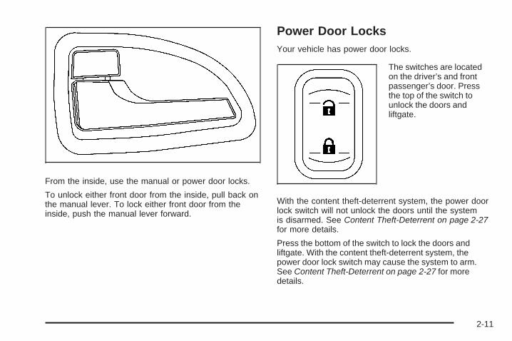
From the inside, use the manual or power door locks.
To unlock either front door from the inside, pull back onthe manual lever. To lock either front door from theinside, push the manual lever forward.
Power Door LocksYour vehicle has power door locks.
The switches are locatedon the driver’s and frontpassenger’s door. Pressthe top of the switch tounlock the doors andliftgate.
With the content theft-deterrent system, the power doorlock switch will not unlock the doors until the systemis disarmed. See Content Theft-Deterrent on page 2-27for more details.
Press the bottom of the switch to lock the doors andliftgate. With the content theft-deterrent system, thepower door lock switch may cause the system to arm.See Content Theft-Deterrent on page 2-27 for moredetails.
2-11

Delayed LockingThis feature allows the locking of the vehicle to bedelayed until all doors have been closed forapproximately five seconds.
To activate the delayed locking feature, do one of thefollowing:
• Press the driver’s door power lock switch one timewhile the driver’s door is open.
• Press the passenger’s door power lock switch onetime while the passenger’s door is open.
• Press the lock button on the remote keyless entrytransmitter one time while any door is open.
Two chimes will sound to signal that delayed locking isactive.
The doors may be locked immediately by repeating anyof the above actions more than one time.
If a door remains open, without any other door beingopened or closed, the vehicle will lock afterapproximately 45 seconds.
If the key is in the ignition, this feature will not lock thedoors.
To turn the delayed locking feature off or on, see DICVehicle Personalization (Uplevel Only) on page 3-76.
Sliding Door Delayed LockingIf either sliding door is open when you use the powerdoor locks to lock the vehicle, the sliding door thatis open will not lock. Normally the delayed lockingfeature will be used to lock the sliding door after it hasbeen closed.
The sliding door delayed locking feature will lock yoursliding door(s) in situations where the delayedlocking feature does not apply or was overridden orprogrammed to be off. See “Delayed Locking” earlier inthis section. Shortly after the last sliding door isclosed, all the doors will lock.
Automatic Door LockAll of the doors will lock automatically when you movethe shift lever out of PARK (P). This feature cannotbe disabled.
If someone needs to get out of the vehicle while it is notin PARK (P), shift into PARK (P), or, have that personuse the manual lever or the power door lock switch.When the door is closed again, it will lock whenthe vehicle exceeds 5 mph (8 km/h).
With automatic door locks, you can lock or unlock thedoors at any time, either manually or by using the powerdoor lock switches.
2-12

Programmable Automatic DoorUnlockYour vehicle was programmed so that all doors willunlock automatically when the shift lever is moved intoPARK (P).
To change the way the automatic door unlockingoperates, see DIC Vehicle Personalization (UplevelOnly) on page 3-76.
Lockout ProtectionThe lockout protection feature makes it more difficult tolock the key in the vehicle. If the driver’s door isopen while the key is in the ignition, the door cannot belocked with the power door lock switch.
This feature cannot guarantee that you will never belocked out of the vehicle. If the key is not left inthe ignition, or, if the manual door lock is used, the keycould still be locked inside the vehicle. Alwaysremember to take the key with you.
Dual Sliding DoorsTo open either sliding door from outside the vehicle, pullthe handle out and then pull the door toward the rear.If you slide the door all the way back, the door will rest ina detent position.
To move the door forward, you must first pull the doorpast the open detent position.
The driver’s side sliding door is designed to open only alittle if the fuel door is open. If this ever happens, donot try to force the sliding door. Just close the driver’sside sliding door. Then when the fuel filler door isclosed, the driver’s side sliding door can be openednormally.
2-13

Sliding Door Lock{CAUTION:
If your vehicle is facing downward on a steepgrade (15 percent or more), the door may notstay open and could slam shut, possiblyinjuring someone. To make sure the door doesnot slam shut be sure to hold it open untileveryone is clear of the door, and only thenallow it to slowly close.
2-14

Lock either sliding door from inside the vehicle bymoving the manual lever down. Unlock it by moving thelever up.
With the power door locks, the sliding door lock has adelay feature. See Delayed Locking on page 2-12and DIC Vehicle Personalization (Uplevel Only) onpage 3-76.
Sliding Door Security LockYour vehicle is equipped with sliding door security locksthat helps prevent young children or other passengersfrom opening the sliding door(s) using the insidedoor handle. To use one of these locks, do the following:
1. Open the sliding door.
2. On the inside of thesliding door(s), on thefront edge of thedoor will be a lock.Push the leverup to engage the lock.
3. Close the door.
4. Repeat Steps 1 through 3 for the other door.
2-15

If your vehicle has power sliding door(s), you canprevent power opening of the sliding door from thepassenger power sliding door (PSD) activation switch bypressing the PSD second row passenger override(deactivation) switch located on the overhead console.See Power Sliding Door (PSD) on page 2-16.
If you want to open the sliding door while the securitylock is on, unlock and open the door from the outside.
You should let adults and older children know howthe security lock works, and how to cancel the lock. Ifyou do not, adults or older children who ride in the rearwill not be able to open the sliding door from theinside while the security lock feature is in use.
Canceling the Sliding DoorSecurity Lock1. Unlock the sliding door and open the door from the
outside.
2. Push the security lock lever all the way down.
3. Close the door.
4. Repeat Steps 1 through 3 for the other door.
The sliding door lock will now work normally.
Power Sliding Door (PSD)If your vehicle has this feature, you can open and closethe power sliding door(s) using the switches insideyour vehicle. You can also operate the sliding door(s)with your remote keyless entry transmitter. See RemoteKeyless Entry (RKE) System on page 2-4.
{CAUTION:
Leaving your children or pets unattended inyour vehicle can be dangerous. They couldoperate the power sliding door. A child orothers could be injured. Do not leave childrenor pets unattended in your vehicle.
2-16

Power Sliding Door (PSD) SwitchesYour vehicle will have one of the following switch(es)located on the overhead console switchbank.
If your vehicle has a singlepower sliding door (PSD),you have this switch.
If your vehicle has dualpower sliding doors, youhave these switches.
PSD Activation/Override(Deactivation) Switch
Driver’s Side andPassenger’s Side PSD
Activation/Override(Deactivation) Switches
2-17

Your vehicle also haspassenger power slidingdoor activation switch(es).
If you have a single PSD, this switch is located in frontof the passenger side sliding door. If your vehiclehas dual PSDs, the switches are located in front of bothsliding doors.
Power Sliding Door OperationThe power sliding door(s) will only open if the transaxle isin PARK (P). The transaxle does not have to be inPARK (P) to close the door(s).
There are several ways to open and close the powersliding door(s).• If your vehicle has a single power sliding door, press
the top of the overhead console PSD activation/override (deactivation) switch.
• If your vehicle has dual power sliding doors, pressthe top of the driver’s side and/or passenger’s sideoverhead console PSD activation/override(deactivation) switch.
• Press the passenger PSD activation switch. Thisswitch will also stop a moving door immediately.
• Press the power sliding door button on the remotekeyless entry transmitter.
• To manually open the power sliding door(s) while theswitch(es) are in the activation position, pull andrelease the inside or outside door handle to releasethe door latch. The door will fully open.
• To manually close the power sliding door(s) while theswitches are in the activation position, pull the insideor outside door handle or the edge of the door. Movethe door about 4 inches (10 cm) toward the closedposition and release it. The door will close completelyand latch.
Passenger PSDActivation Switch
2-18

If a power sliding door is locked, it cannot be unlockedand opened using the overhead console PSDswitch(es) or the passenger PSD activation switch(es).The power sliding door must either be manuallyunlocked or unlocked using the power door unlockswitch located on the driver’s or front passenger’sarmrest, and then opened using the overhead orpassenger PSD activation switch(es).The remote keyless entry transmitter can also be used toopen the power sliding door(s). If the vehicle is locked,press the power sliding door button(s) and all doors willunlock and the sliding door(s) will open. See RemoteKeyless Entry (RKE) System Operation on page 2-5.
If the power sliding door has been manually locked, youmust unlock the PSD before it can be opened.
Notice: If you leave the power sliding door on whenyou go through an automatic car wash, the door mayaccidentally open. Be sure the power sliding door isturned off when going through a car wash.
If the power sliding door(s) is open or in the process ofclosing when you shift out of PARK (P), a chime willsound. This is a warning that the sliding door(s) is notcompletely closed. Also, the Driver InformationCenter (DIC) will indicate if the door is open. See DICWarnings and Messages on page 3-58. Stop the vehicleand close the door.
{CAUTION:
If you shift the transaxle out of PARK (P) andaccelerate before the power sliding doorlatches closed, the door may reverse to theopen position. A child or others could fall outof the vehicle and be injured. Always makesure the power sliding door is closed andlatched before you drive away.
2-19

If an object obstructs the power sliding door(s) while it isclosing, the door will automatically reverse to theopen position, provided it meets sufficient resistance.Resistance must be as strong as the force of the closingdoor, or stronger. The force of the closing doorincreases significantly as the door approaches thelatched position.
The driver’s side sliding door is designed to open only alittle if the fuel door is open. If this ever happens, donot try to force the sliding door. When the fuel filler dooris closed, the driver’s side sliding door can be openednormally.
{CAUTION:
You or others could be injured if caught in thepath of the sliding door. Make sure the doorpath is clear before opening or closing the door.
2-20

{CAUTION:
If your vehicle is facing downward on a steepgrade (15 percent or more), the door may notstay open and could slam shut, possiblyinjuring someone. To make sure the door doesnot slam shut, turn on the power sliding doorfeature. Then if the door closes, it will closeunder the control of the power door system.
Power Sliding Door Second RowPassenger Override (Deactivation)To help avoid accidental operation of the sliding door(s)by using the passenger PSD activation switch, pressthe override (deactivation) part of the overhead consoleswitch. The door can still be manually opened fromthe inside or outside with the override (deactivation) on.
To open a power sliding door(s) manually when theoverhead console switch is in override (deactivation)position, pull the inside or outside door handle and slidethe door all the way back.
To close the door(s) manually when the overrideswitch(es) is in the override (deactivation) position, pullthe inside or outside door handle and slide the doorall the way forward to the latched position.
To stop the door(s) immediately while the door(s) isopening or closing, press the PSD override(deactivation) part of the switch.
Pressing the PSD button(s) on the remote keyless entrywill open and close the door unless the door hasbeen manually locked using the mechanical slider.
Resetting the Power Sliding DoorThe power sliding door may operate incorrectly or not atall because of the following conditions:
• A low voltage or dead battery
• A disconnected battery
• If the instrument panel PSD/fuse 21, LHPSD/fuse24 or RHPSD/fuse 25 are removed or blown.
See Fuses and Circuit Breakers on page 5-100 for moreinformation.
2-21

If any of these conditions occur, the power sliding doormay need to be reset. If your vehicle has the dualpower sliding doors, both doors will have to be reset. Toreset a door, do the following:
1. Check to be sure the power sliding door is unlockedand securely closed.
2. Turn the ignition to LOCK.
3. If the power sliding door overhead console switch isin the override (deactivation) position, return to theactivation position.
4. Open the sliding door using the remote keylessentry transmitter, overhead console switch,or passenger switch. Allow the door to travelfully open.
If the door does not travel to the fully open position,press the overhead console switch to the override(deactivation) position and slide the door fully open andclosed. Check for foreign objects in the tracks. Repeatthe procedure starting with Step 1. If the door resiststravel to the fully open position, see your dealerfor service.
LiftgateTo unlock or lock the liftgate from the outside, use theremote keyless entry transmitter. For more information,see Remote Keyless Entry (RKE) System Operationon page 2-5.
You can also use the power door lock switch to lockand unlock the liftgate.
Open the liftgate using the handle located above thelicense plate. Once slightly opened, the liftgate will riseby itself. Lamps in the rear of the vehicle will comeon, illuminating the rear cargo area.
Notice: If you open the liftgate without checking foroverhead obstructions such as a garage door,you could damage the liftgate or the liftgate glass.Always check to make sure the area above andbehind the liftgate is clear before opening it.
2-22

{CAUTION:
It can be dangerous to drive with the liftgateopen because carbon monoxide (CO) gas cancome into your vehicle. You cannot see orsmell CO. It can cause unconsciousness andeven death. If you must drive with the liftgateopen or if electrical wiring or other cableconnections must pass through the sealbetween the body and the liftgate:
• Make sure all other windows are shut.• Turn the fan on your heating or cooling
system to its highest speed and select thecontrol setting that will force outside airinto your vehicle. See Climate ControlSystem on page 3-24 or Dual ClimateControl System on page 3-27.
• If you have air outlets on or under theinstrument panel, open them all the way.See Engine Exhaust on page 2-41.
To close the liftgate, pull down on the handle, thenfirmly shut the liftgate. Do not drive with the liftgate open,even slightly.
2-23

Windows
{CAUTION:
Leaving children, helpless adults, or pets in avehicle with the windows closed is dangerous.They can be overcome by the extreme heatand suffer permanent injuries or even deathfrom heat stroke. Never leave a child, ahelpless adult, or a pet alone in a vehicle,especially with the windows closed in warm orhot weather.
2-24

Power Windows
{CAUTION:
Leaving children, helpless adults, or pets in avehicle with the windows closed is dangerous.They can be overcome from extreme heat inwarm or hot weather and suffer permanentinjuries or even death from heat stroke.
Leaving children in a vehicle with the ignitionkey is dangerous for many reasons, childrenor others could be badly injured or even killed.They could operate the power windows orother controls or even make the vehicle move.The windows will function with the keys in theignition and they could be seriously injured orkilled if caught in the path of a closingwindow. Do not leave keys in a vehicle withchildren.
When there are children in the rear seat usethe window lockout button to preventunintentional operation of the windows.
The switches on thedriver’s door armrestcontrol the front windowswhen the ignition is inRUN, ACCESSORYor when RetainedAccessory Power (RAP) isactive. See RetainedAccessory Power (RAP)on page 2-32.
The driver’s power window switch has two downpositions. The first position lowers the window normally.
To raise the window, pull up the front of the switch.
Express-Down WindowTo activate the express-down feature, push the AUTOswitch all the way down to the second position, thenrelease it. The window will lower completely. To stop thewindow from lowering all the way, pull up on the frontof the switch.
2-25

Manual Rear Quarter WindowsYour vehicle may have manual rear quarter windows.
To open, pull the latchforward to release it, thenswing the windowoutward. Press the centerof the latch to securethe window in the openposition.
To close, pull the center of the latch forward and thenclose the latch. Press the center of the latch tosecure the window in the closed position.
Power Rear Quarter WindowsYour vehicle may have power rear quarter windows.
This switch, located in theoverhead consoleswitchbank, is used foropening and closingthe power rear quarterwindows.
Press the top of the switch to open the windows; bothwindows will open. The windows will continue to open aslong as the switch is pressed, until they are fullyopened.
Press the bottom of the switch to close both windows.The windows can be closed fully or partially, dependingon how long the switch is pressed.
The ignition must be in RUN, ACCESSORY, or RetainedAccessory Power (RAP) must be active, to use thepower rear quarter windows. See Retained AccessoryPower (RAP) on page 2-32.
2-26

Sun VisorsTo block out glare, swing down the sun visors. You canalso remove them from the center mount and swingthem to the side. The sun visors can also slide along therod to cover different areas of the front window.
Visor Vanity MirrorYour vehicle may have a visor vanity mirror. Pull downthe sun visor to access the vanity mirror.
Lighted Vanity MirrorYour vehicle may have a lighted vanity mirror. Pull downthe sun visor and flip up the cover to expose the vanitymirror. The lamps will come on when you flip up thecover.
Theft-Deterrent SystemsVehicle theft is big business, especially in some cities.Although your vehicle has a number of theft-deterrentfeatures, we know that nothing we put on it can make itimpossible to steal.
Content Theft-DeterrentYour vehicle may have a theft-deterrent alarm system.
A light located on top of your instrument panel, near thecenter of the vehicle next to the windshield, will flashslowly to let you know that the system has been armed.
While armed, the doors will not unlock with the powerdoor lock switch.Once armed, the alarm will go off if someone tries to enterthe vehicle without using the remote keyless entrytransmitter or a key, or turns the ignition to ON/RUN.The horn will sound and the turn signal lamps will flashfor up to two minutes.
2-27

Arming with the Power Lock SwitchYour alarm system will arm when the key is removedfrom the ignition and you use the driver’s powerdoor lock switch, with the driver’s door open or thepassenger’s door power door lock switch with thepassenger’s door open to lock the vehicle. If you wouldlike to turn on power door lock switch arming, seeDIC Vehicle Personalization (Uplevel Only) onpage 3-76.
When the security light flashes quickly the system isarming. After all doors and the liftgate are closedand locked, the security light will begin flashing at avery slow rate to let you know the system is armed.
Arming with the Remote Keyless EntryTransmitterYour alarm system will arm if the key is not in theignition and you use your remote keyless entrytransmitter to lock the doors. The security light will flashto let you know the system is arming. If you pressthe transmitter’s lock button twice within five seconds,the horn will sound. After all doors and the liftgateare closed and locked, the security light will beginflashing at a very slow rate to let you know the systemis armed.
Arming with Your KeyYour alarm system will arm when you use your key tolock the driver’s door. The security light will flash tolet you know the system is arming. After all doors andthe liftgate are closed and locked, the security lightwill begin flashing at a very slow rate to let you know thesystem is armed. If you would like your key not toarm the system, see DIC Vehicle Personalization(Uplevel Only) on page 3-76.
Arming ConfirmationIf remote unlock confirmation is on, the turn signallamps will flash briefly to let you know when your alarmsystem has disarmed. If you would not like the turnsignal lamps to flash, see DIC Vehicle Personalization(Uplevel Only) on page 3-76.
Disarming with the Remote KeylessEntry TransmitterYour alarm system will disarm when you use yourremote keyless entry transmitter to unlock the doors.The security light will stop flashing to let you know thesystem is no longer armed.
2-28

Disarming with Your KeyYour alarm system will disarm when you use your keyto unlock the driver’s door. The security light willstop flashing to let you know the system is no longerarmed. If you would like your key not to disarm the alarmsystem, see DIC Vehicle Personalization (UplevelOnly) on page 3-76.
PASS-Key® IIIYour PASS-Key® III system operates on a radiofrequency subject to Federal CommunicationsCommission (FCC) Rules and with Industry Canada.
This device complies with Part 15 of the FCC Rules.Operation is subject to the following two conditions:
1. This device may not cause harmful interference.
2. This device must accept any interference received,including interference that may cause undesiredoperation.
This device complies with RSS-210 of Industry Canada.Operation is subject to the following two conditions:
1. This device may not cause interference.
2. This device must accept any interference received,including interference that may cause undesiredoperation of the device.
Changes or modifications to this system by other thanan authorized service facility could void authorization touse this equipment.
PASS-Key® III uses a radio frequency transponder inthe key that matches a decoder in your vehicle.
PASS-Key® III OperationYour vehicle is equipped with the PASS-Key® III(Personalized Automotive Security System)theft-deterrent system. PASS-Key® III is a passive theftdeterrent system.
The system is automatically armed when the key isremoved from the ignition.
You do not have to manually arm or disarm the system.
The security light will come on if there is a problemwith arming or disarming the theft-deterrent system.
When the PASS-Key® III system senses that someoneis using the wrong key, it shuts down the vehicle’sstarter and fuel systems. The starter will not work andfuel will stop being delivered to the engine. Anyoneusing a trial-and-error method to start the vehicle will bediscouraged because of the high number of electricalkey codes.
If the engine does not start and the security messagecomes on, there may be a problem with yourtheft-deterrent system. Turn the ignition off and try again.
2-29

If the engine still does not start, and the key appears tobe undamaged, try another ignition key. If the enginestill does not start with the other key, your vehicle needsservice. If your vehicle does start, the first key may befaulty. See your dealer/retailer or a locksmith whocan service the PASS-Key® III to have a new key made.
It is possible for the PASS-Key® III decoder to learnthe transponder value of a new or replacement key.Up to 10 keys may be programmed for the vehicle.This procedure is for learning additional keys only. If allthe currently programmed keys are lost or do notoperate, you must see your dealer/retailer or a locksmithwho can service PASS-Key® III to have keys madeand programmed to the system.
See your dealer/retailer or a locksmith who can servicePASS-Key® III to get a new key blank that is cutexactly as the ignition key that operates the system.
To program the new key:
1. Verify the new key has PK3 stamped on it.
2. Insert the original, already programmed key into theignition lock cylinder and start the engine. If theengine will not start, see your dealer/retailerfor service.
3. After the engine has started, turn the key toLOCK/OFF and remove the key.For vehicles first sold in Canada, repeat step 2with a different, already programmed, key beforeproceeding to step 4.
4. Insert the key to be programmed and turn it toON/RUN within 10 seconds of removing theprevious key.The security message will turn off once the key hasbeen programmed. It may not be apparent thatthe security message went on due to how quicklythe key is programmed.
5. Repeat Steps 1 through 4 if additional keys are tobe programmed.
If you are ever driving and the security message comeson and stays on, you will be able to restart yourengine if you turn it off. Your PASS-Key® III system,however, is not working properly and must be servicedby your dealer/retailer. Your vehicle is not protectedby the PASS-Key® III system at this time.
If you lose or damage a PASS-Key® III key, see yourdealer/retailer or a locksmith who can servicePASS-Key® III to have a new key made.
Do not leave the key or device that disarms ordeactivates the theft deterrent system in the vehicle.
2-30

Starting and Operating YourVehicle
New Vehicle Break-InNotice: Your vehicle does not need an elaboratebreak-in. But it will perform better in the long run ifyou follow these guidelines:
• Do not drive at any one constant speed, fast orslow, for the first 500 miles (805 km). Do notmake full-throttle starts. Avoid downshifting tobrake or slow the vehicle.
• Avoid making hard stops for the first 200 miles(322 km) or so. During this time the new brakelinings are not yet broken in. Hard stopswith new linings can mean premature wear andearlier replacement. Follow this breaking-inguideline every time you get new brake linings.
• Do not tow a trailer during break-in. See Towinga Trailer on page 4-28 for the trailer towingcapabilities of your vehicle and moreinformation.
Following break-in, engine speed and load can begradually increased.
Ignition PositionsThe key can be turned to one of four positions while in theignition switch.
In order to shift out of PARK (P), ignition must be in theON/RUN or ACC/ACCESSORY and the regular brakepedal must be applied.
A (LOCK/OFF): This is the only position from which youcan remove the key. This position locks your ignition andtransmission.
Notice: Using a tool to force the key from theignition switch could cause damage or break the key.Use the correct key and turn the key only with yourhand. Make sure the key is all the way in. If none ofthis works, then your vehicle needs service.
2-31

B (ACC/ACCESSORY): This is the position in whichyou can operate the electrical accessories, such as theradio.
C (ON/RUN): This is the position to which the switchreturns after the engine is started and the ignition key isreleased. This is the position for driving. Even whilethe engine is not running, ON/RUN can be usedto operate your electrical accessories and to displaysome instrument panel warning lights.
The battery could be drained if you leave the key in theACC/ACCESSORY or ON/RUN position with theengine off. You may not be able to start your vehicle ifthe battery is allowed to drain for an extended periodof time.
D (START): This position starts the engine. When theengine starts, release the ignition key. The switchwill return to ON/RUN for driving.
Key In the IgnitionNever leave your vehicle with the keys inside, as it is aneasy target for joy riders or thieves. If you leave thekey in the ignition and park your vehicle, a chimewill sound, when you open the driver’s door. Alwaysremember to remove your key from the ignition and takeit with you. This will lock your ignition and transmission.Also, always remember to lock the doors.
The battery could be drained if you leave the key in theignition while your vehicle is parked. You may not beable to start your vehicle after it has been parked for anextended period of time.
Retained Accessory Power (RAP)These vehicle accessories can be used for up to10 minutes after the engine is turned off:
• Audio System
• Power Windows
These features continue to work up to 10 minutes afterthe engine is turned off or until either door is opened.If a door is opened, the power windows and audiosystem will shut off.
Starting the EngineMove your shift lever to PARK (P) or NEUTRAL (N).Your engine will not start in any other position – this is asafety feature. To restart when you are alreadymoving, use NEUTRAL (N) only.
Notice: Do not try to shift to PARK (P) if yourvehicle is moving. If you do, you could damage thetransmission. Shift to PARK (P) only when yourvehicle is stopped.
2-32

Starting Procedure1. With your foot off the accelerator pedal, turn the
ignition key to START. When the engine starts,let go of the key. The idle speed will go down asyour engine gets warm. Do not race the engineimmediately after starting it. Operate the engine andtransmission gently to allow the oil to warm upand lubricate all moving parts.Your vehicle has a Computer-Controlled CrankingSystem. This feature assists in starting theengine and protects components. If the ignition keyis turned to the START position, and thenreleased when the engine begins cranking, theengine will continue cranking for a few seconds oruntil the vehicle starts. If the engine does notstart and the key is held in START for manyseconds, cranking will be stopped after 15 secondsto prevent cranking motor damage. To preventgear damage, this system also prevents cranking ifthe engine is already running. Engine crankingcan be stopped by turning the ignition switch to theACC/ACCESSORY or LOCK/OFF position.
Notice: Cranking the engine for long periods oftime, by returning the key to the START positionimmediately after cranking has ended, can overheatand damage the cranking motor, and drain thebattery. Wait at least 15 seconds between each try,to let the cranking motor cool down.
2. If the engine does not start after 5-10 seconds,especially in very cold weather (below 0°For −18°C), it could be flooded with too muchgasoline. Try pushing the accelerator pedal all theway to the floor and holding it there as you holdthe key in START for up to a maximum of15 seconds. Wait at least 15 seconds betweeneach try, to allow the cranking motor to cool down.When the engine starts, let go of the key andaccelerator. If the vehicle starts briefly but thenstops again, do the same thing. This clears the extragasoline from the engine. Do not race the engineimmediately after starting it. Operate the engine andtransmission gently until the oil warms up andlubricates all moving parts.
Notice: The engine is designed to work with theelectronics in your vehicle. If you add electricalparts or accessories, you could change the way theengine operates. Before adding electrical equipment,check with your dealer/retailer. If you do not, yourengine might not perform properly. Any resultingdamage would not be covered by your vehicle’swarranty.
2-33
Engine Coolant HeaterThe engine coolant heater, if available, can help in coldweather conditions at or below 0°F (−18°C) for easierstarting and better fuel economy during engine warm-up.Plug in the coolant heater at least four hours beforestarting your vehicle. An internal thermostat in theplug-end of the cord may exist which will prevent enginecoolant heater operation at temperatures.
To Use the Engine Coolant Heater1. Turn off the engine.
2. Open the hood and unwrap the electrical cord. Theelectrical cord is located on the driver’s side of theengine compartment.
3. Plug it into a normal, grounded 110-volt AC outlet.
{CAUTION:
Plugging the cord into an ungrounded outletcould cause an electrical shock. Also, thewrong kind of extension cord could overheatand cause a fire. You could be seriouslyinjured. Plug the cord into a properly groundedthree-prong 110-volt AC outlet. If the cord willnot reach, use a heavy-duty three-prongextension cord rated for at least 15 amps.
4. Before starting the engine, be sure to unplug andstore the cord as it was before to keep it awayfrom moving engine parts. If you do not, it could bedamaged.
How long should you keep the coolant heater pluggedin? The answer depends on the outside temperature, thekind of oil you have, and some other things. Insteadof trying to list everything here, we ask that you contactyour dealer/retailer in the area where you will beparking your vehicle. The dealer/retailer can give youthe best advice for that particular area.
2-34

Automatic Transmission Operation
Maximum engine speed is limited when you are inPARK (P) or NEUTRAL (N), to protect drivelinecomponents from improper operation.
There are several different positions for your shift lever.
PARK (P): This gear position locks your front wheels.It is the best position to use when you start your enginebecause your vehicle cannot move easily.
Make sure the shift lever is fully in PARK (P) beforestarting the engine. Your vehicle has an automatictransmission shift lock control system. You must fullyapply your regular brakes first before you can shift from
PARK (P) when the ignition key is in ON/RUN. If youcannot shift out of PARK (P), ease pressure on theshift lever and push the shift lever all the way intoPARK (P) as you maintain brake application. Thenpress the shift lever button and move the shift lever intoanother gear. See Shifting Out of PARK (P) onpage 2-40.
{CAUTION:
It is dangerous to get out of your vehicle if theshift lever is not fully in PARK (P) with theparking brake firmly set. Your vehicle can roll.
Do not leave your vehicle when the engine isrunning unless you have to. If you have left theengine running, the vehicle can movesuddenly. You or others could be injured. Tobe sure your vehicle will not move, even whenyou are on fairly level ground, always set yourparking brake and move the shift lever toPARK (P). See Shifting Into PARK (P) onpage 2-38. If you are pulling a trailer, seeTowing a Trailer on page 4-28.
2-35

REVERSE (R): Use this gear to back up.
Notice: Shifting to REVERSE (R) while your vehicleis moving forward could damage the transmission.The repairs would not be covered by your warranty.Shift to REVERSE (R) only after your vehicle isstopped.
To rock your vehicle back and forth to get out of snow,ice or sand without damaging your transmission,see If Your Vehicle is Stuck in Sand, Mud, Ice, or Snowon page 4-20.
NEUTRAL (N): In this position, your engine does notconnect with the wheels. To restart when you arealready moving, use NEUTRAL (N) only. Also, useNEUTRAL (N) when your vehicle is being towed.
{CAUTION:
Shifting into a drive gear while the engine isrunning at high speed is dangerous. Unlessyour foot is firmly on the brake pedal, yourvehicle could move very rapidly. You couldlose control and hit people or objects. Do notshift into a drive gear while your engine isrunning at high speed.
Notice: Shifting out of PARK (P) or NEUTRAL (N)with the engine running at high speed may damagethe transmission. The repairs would not becovered by your warranty. Be sure the engine is notrunning at high speed when shifting your vehicle.
DRIVE (D): This position is for normal driving. Itprovides the best fuel economy for your vehicle. If youneed more power for passing, and you are:
• Going less than 35 mph (55 km/h), push youraccelerator pedal about halfway down.
• Going about 35 mph (55 km/h) or more, push theaccelerator all the way down.The vehicle will shift down to the next gear andhave more power.
Downshifting the transmission in slippery road conditionscould result in skidding, see Skidding under Loss ofControl on page 4-12
Notice: If your vehicle seems to start up ratherslowly or not shift gears when you go faster, andyou continue to drive your vehicle that way, youcould damage the transmission. Have your vehicleserviced right away. You can drive in SECOND (2)when you are driving less than 35 mph (55 km/h) andDRIVE (D) for higher speeds until then.
2-36

Warm-Up ShiftYour vehicle has a computer controlled transmissiondesigned to warm up the engine faster when the outsidetemperature is 35°F (2°C) or colder. You may notice thatthe transmission will shift at a higher vehicle speed untilthe engine is warmed up. This is a normal conditiondesigned to provide heat to the passenger compartmentand defrost the windows more quickly. See ClimateControl System on page 3-24 and Dual Climate ControlSystem on page 3-27 for more information.
THIRD (3): This position is also used for normal driving.It reduces vehicle speed more than DRIVE (D) withoutusing your brakes. You might choose THIRD (3) insteadof DRIVE (D) when driving on hilly, winding roads, whentowing a trailer, so there is less shifting between gearsand when going down a steep hill.
SECOND (2): This position reduces vehicle speed morethan DRIVE (D) without using your brakes. You can useSECOND (2) on hills. It can help control your speed asyou go down steep mountain roads, but then you wouldalso want to use your brakes off and on.
Notice: Driving in SECOND (2) for more than25 miles (40 km) or at speeds over 55 mph (90 km/h)may damage the transmission. Also, shifting intoSECOND (2) at speeds above 65 mph (105 km/h) cancause damage. Drive in THIRD (3) or DRIVE (D)instead of SECOND (2).
Notice: If your vehicle seems to start up ratherslowly, or if it seems not to shift gears as you gofaster, something may be wrong with a transmissionsystem sensor. If you drive very far that way, yourvehicle can be damaged. So, if this happens, haveyour vehicle serviced right away. Until then, you canuse SECOND (2) when you are driving less than35 mph (55 km/h) and THIRD (3) for higher speeds.
FIRST (1): This position reduces vehicle speed evenmore than SECOND (2) without using your brakes. Youcan use it on very steep hills, or in deep snow ormud. If the shift lever is put in FIRST (1) while thevehicle is moving forward, the transmission will not shiftinto first gear until the vehicle is going slowly enough.
Notice: Spinning the tires or holding the vehicle inone place on a hill using only the acceleratorpedal may damage the transmission. The repair willnot be covered by your warranty. If you are stuck,do not spin the tires. When stopping on a hill,use the brakes to hold the vehicle in place.
2-37

Parking BrakeThe parking brake islocated under theinstrument panel on thedriver’s side of the vehicle.
To set the parking brake, hold the regular brake pedaldown with your right foot and push down on the parkingbrake pedal with your left foot.If the ignition is on, the brake system warning light willcome on. See Brake System Warning Light on page 3-41.To release the parking brake, hold the regular brakepedal down with your right foot while you push down onthe parking brake pedal with your left foot. When you liftyour left foot from the parking brake pedal, it will pop up tothe released position.
Notice: Driving with the parking brake on canoverheat the brake system and cause premature wearor damage to brake system parts. Make sure that theparking brake is fully released and the brake warninglight is off before driving.
If you are towing a trailer and are parking on any hill,see Towing a Trailer on page 4-28.
Shifting Into PARK (P)
{CAUTION:
It can be dangerous to get out of your vehicleif the shift lever is not fully in PARK (P) withthe parking brake firmly set. Your vehicle canroll. If you have left the engine running, thevehicle can move suddenly. You or otherscould be injured. To be sure your vehicle willnot move, even when you are on fairly levelground, use the steps that follow. If you arepulling a trailer, see Towing a Trailer onpage 4-28.
1. Hold the brake pedal down with your right foot andset the parking brake. See Parking Brake onpage 2-38
2. Move the shift lever into PARK (P) by pulling theshift lever toward you and moving it up as far as itwill go.
2-38

3. Turn the ignition key to LOCK/OFF.
4. Remove the key and take it with you. If you canleave your vehicle with the ignition key in yourhand, your vehicle is in PARK (P).
Leaving Your Vehicle With the EngineRunning
{CAUTION:
It can be dangerous to leave your vehicle withthe engine running. Your vehicle could movesuddenly if the shift lever is not fully inPARK (P) with the parking brake firmly set.And, if you leave the vehicle with the enginerunning, it could overheat and even catch fire.You or others could be injured. Do not leaveyour vehicle with the engine running.
If you have to leave your vehicle with the enginerunning, be sure your vehicle is in PARK (P) and theparking brake is firmly set before you leave it. After youmove the shift lever into PARK (P), hold the regularbrake pedal down. Then, see if you can move the shiftlever away from PARK (P) without first pulling ittoward you. If you can, it means that the shift lever wasnot fully locked into PARK (P).
Torque LockIf you are parking on a hill and you do not shift yourvehicle into PARK (P) properly, the weight of the vehiclemay put too much force on the parking pawl in thetransmission. You may find it difficult to pull the shift leverout of PARK (P). This is called torque lock. To preventtorque lock, set the parking brake and then shift intoPARK (P) properly before you leave the driver’s seat. Tofind out how, see Shifting Into PARK (P) on page 2-38.
When you are ready to drive, move the shift lever out ofPARK (P) before you release the parking brake.
If torque lock does occur, you may need to have anothervehicle push yours a little uphill to take some of thepressure from the parking pawl in the transmission, soyou can pull the shift lever out of PARK (P).
2-39

Shifting Out of PARK (P)This vehicle is equipped with an electronic shift lockrelease system. The shift lock release is designed to:
• Prevent ignition key removal unless the shiftlever is in PARK (P) with the shift lever button fullyreleased, and
• Prevent movement of the shift lever out of PARK (P),unless the ignition is in ON/RUN or ACC/ACCESSORY and the regular brake pedal is applied.
The shift lock release is always functional except in thecase of an uncharged or low voltage (less than 9 volt)battery.
If your vehicle has an uncharged battery or a batterywith low voltage, try charging or jump starting thebattery. See Jump Starting on page 5-37 for moreinformation.
To shift out of PARK (P) use the following:
1. Apply the brake pedal.
2. Move the shift lever to the desired position.
If you still are unable to shift out of PARK (P):
1. Ease the pressure on the shift lever.
2. While holding down the brake pedal, press the shiftlever all the way into PARK (P).
3. Move the shift lever to the desired position.
If you are still having a problem shifting, then have yourvehicle serviced soon.
Parking Over Things That Burn
{CAUTION:
Things that can burn could touch hot exhaustparts under your vehicle and ignite. Do notpark over papers, leaves, dry grass, or otherthings that can burn.
2-40

Engine Exhaust
{CAUTION:
Engine exhaust can kill. It contains the gascarbon monoxide (CO), which you cannot seeor smell. It can cause unconsciousness anddeath.
You might have exhaust coming in if:• The exhaust system sounds strange or
different.• Your vehicle gets rusty underneath.• Your vehicle was damaged in a collision.
CAUTION: (Continued)
CAUTION: (Continued)
• Your vehicle was damaged when drivingover high points on the road or over roaddebris.
• Repairs were not done correctly.• Your vehicle or the exhaust system has
been modified improperly.
If you ever suspect exhaust is coming intoyour vehicle:
• Drive it only with all the windows down toblow out any CO; and
• Have your vehicle fixed immediately.
2-41

Running the Engine While ParkedIt is better not to park with the engine running. But if youever have to, here are some things to know.
{CAUTION:
Idling the engine with the climate controlsystem off could allow dangerous exhaust intoyour vehicle. See the earlier caution underEngine Exhaust on page 2-41.
Also, idling in a closed-in place can let deadlycarbon monoxide (CO) into your vehicle even ifthe climate control fan is at the highest setting.One place this can happen is a garage.Exhaust — with CO — can come in easily.NEVER park in a garage with the enginerunning.
Another closed-in place can be a blizzard. SeeWinter Driving on page 4-17.
{CAUTION:
It can be dangerous to get out of your vehicleif the shift lever is not fully in PARK (P) withthe parking brake firmly set. Your vehicle canroll. Do not leave your vehicle when the engineis running unless you have to. If you have leftthe engine running, the vehicle can movesuddenly. You or others could be injured. Tobe sure your vehicle will not move, even whenyou are on fairly level ground, always set theparking brake and move the shift lever toPARK (P).
Follow the proper steps to be sure your vehicle will notmove. See Shifting Into PARK (P) on page 2-38.
If you are pulling a trailer, see Towing a Trailer onpage 4-28.
2-42

Mirrors
Manual Rearview MirrorWhen you are sitting in a comfortable driving position,adjust the mirror so you can see clearly behind yourvehicle. Hold the mirror in the center to move it up ordown and side to side. The day/night adjustment allowsyou to adjust the mirror to avoid glare from the lampsbehind you. Push the tab forward for daytime useand pull it for nighttime use.
Outside Power Mirrors
The controls, located onthe driver’s door, operateboth outside rearviewmirrors.
Push the top control to the left or right to choose eitherthe driver’s or passenger’s outside rearview mirror.Leave the control in the center position to preventmoving the mirrors once they are adjusted.
Use the arrows on the bottom control to adjust theposition of each mirror. Adjust each mirror so that youcan see the side of your vehicle and the area behind it,while sitting in a comfortable driving position.
Both outside mirrors can be folded forward or rearwardto prevent damage when going through car washesor confined spaces.
2-43

Outside Convex Mirror
{CAUTION:
A convex mirror can make things (like othervehicles) look farther away than they really are.If you cut too sharply into the right lane, youcould hit a vehicle on your right. Check yourinside mirror or glance over your shoulderbefore changing lanes.
The passenger side mirror is convex. A convex mirror’ssurface is curved so more can be seen from thedriver’s seat. It also makes things, like other vehicles,look farther away than they really are.
Outside Heated MirrorsIf the vehicle has outside heated rearview mirrors, theyare activated when the rear window defogger isturned on. See “Rear Window Defogger” in ClimateControl System on page 3-24 or Dual Climate ControlSystem on page 3-27.
Object Detection Systems
Ultrasonic Rear ParkingAssist (URPA)If your vehicle has the Ultrasonic Rear Parking Assist(URPA) system, it helps you park easier and avoid othervehicles while in REVERSE (R). It operates at speedsless than 3 mph (5 km/h). It can determine howclose objects are to the rear bumper, up to 5 feet (1.5 m)behind your vehicle. The distance sensors are locatedon the rear bumper.
2-44

{CAUTION:
The Ultrasonic Rear Parking Assist (URPA)system does not replace driver vision.It cannot detect:
• objects that are below the bumper,underneath the vehicle, or if they aretoo close or far from the vehicle
• children, pedestrians, bicyclists, or pets.
If you do not use proper care before and whilebacking; vehicle damage, injury, or deathcould occur. Even with URPA, always checkbehind your vehicle before backing up. Whilebacking, be sure to look for objects and checkyour vehicle’s mirrors.
The display is located nearthe rear window and canbe seen by lookingover your right shoulder.
URPA uses three color-coded lights to provide distanceand system information.
2-45

How the System WorksURPA comes on automatically when the shift lever ismoved into REVERSE (R). The rear display will thenbriefly illuminate to let you know the system is working.URPA operates only at speeds less than 3 mph (5 km/h).If you are above this speed, the red light on the reardisplay will flash.To be detected, objects must be at least 10 inches(25.4 cm) off the ground and below liftgate level. Objectsmust also be within 5 feet (1.5 m) from your rear bumper.This distance may be less during warmer or humidweather.A single beep will sound the first time an object isdetected between 20 inches (0.5 m) and 5 feet (1.5 m)away. Repeated beeping will occur when you are closerthan 20 inches (0.5 m) from the object.
The following describes what will occur with the URPAdisplay as you get closer to a detected object:
Description English Metricamber light 5 ft 1.5 m
amber/amber lights 40 in 1.0 mamber/amber/red
lights/continuous beep 20 in 0.5 m
amber/amber/red lightsflashing and
continuous beep1 ft 0.3 m
URPA can be turned off bypressing the rear park aiddisable switch locatedin the overhead consoleswitchbank.
While the system is disabled, an indicator light will be liton the switch. You will not see any lights on the reardisplay if the switch is in the off position.
2-46

When the System Does Not Seem toWork Properly• The driver disabled the system.
• The ultrasonic sensors are not clean, a red URPAdisplay light may illuminate when the vehicle is inREVERSE (R). Keep your rear bumper free of mud,dirt, snow, ice and slush. For cleaning instructions,see Washing Your Vehicle on page 5-93.
• A trailer was attached to your vehicle, or a bicycleor an object was hanging out of your liftgateduring your last drive cycle, the red light mayilluminate. Once the attached object is removed,URPA will return to normal operation.
• A tow bar is attached to your vehicle.
• The vehicle’s bumper is damaged. Take the vehicleto your dealer/retailer to repair the system.
• Other conditions may affect system performance,such as vibrations from a jackhammer or thecompression of air brakes on a very large truck.
If the system is still disabled, after driving forward atleast 15 mph (25 km/h), take your vehicle to yourdealer/retailer.
OnStar® System
OnStar uses several innovative technologies and liveadvisors to provide you with a wide range of safety,security, information, and convenience services. If yourairbags deploy, the system is designed to make anautomatic call to OnStar Emergency advisors who canrequest emergency services be sent to your location.If you lock your keys in the vehicle, call OnStar at1-888-4-ONSTAR and they can send a signal to unlockyour doors. If you need roadside assistance, pressthe OnStar button and they can contact RoadsideService for you.
2-47

OnStar service is provided to you subject to the OnStarTerms and Conditions. You may cancel your OnStarservice at any time by contacting OnStar. A completeOnStar Owner’s Guide and the OnStar Terms andConditions are included in the vehicle’s OnStarSubscriber glove box literature. For more information,visit onstar.com or onstar.ca, contact OnStar at1-888-4-ONSTAR (1-888-466-7827) or TTY1-877-248-2080, or press the OnStar button to speak withan OnStar advisor 24 hours a day, 7 days a week.
Not all OnStar features are available on all vehicles.To check if your vehicle is equipped to provide theservices described below, or for a full description ofOnStar services and system limitations, see the OnStarOwner’s Guide in your glove box or visit onstar.com.
OnStar ServicesFor new vehicles with OnStar, the Safe & Sound Plan,or the Directions & Connections Plan is included forone year from the date of purchase. You can extend thisplan beyond the first year, or upgrade to the Directions& Connections Plan. For more information, pressthe OnStar button to speak with an advisor. SomeOnStar services (such as Remote Door Unlock or StolenVehicle Location Assistance) may not be availableuntil you register with OnStar.
Available Services with Safe & Sound Plan• Automatic Notification of Airbag Deployment
• Advanced Automatic Crash Notification (AACN)(If equipped)
• Link to Emergency Services
• Roadside Assistance
• Stolen Vehicle Location Assistance
• AccidentAssist
• Remote Door Unlock/Vehicle Alert
• OnStar Vehicle Diagnostics
• GM Goodwrench® On Demand Diagnostics
• OnStar Hands-Free Calling with 30 complimentaryminutes
• OnStar Virtual Advisor (U.S. Only)
Available Services included with Directions& Connections Plan• All Safe and Sound Plan Services
• Driving Directions - Advisor delivered or OnStarTurn-by-Turn Navigation (If equipped)
• RideAssist
• Information and Convenience Services
2-48
OnStar Hands-Free CallingOnStar Hands-Free Calling allows eligible OnStarsubscribers to make and receive calls using voicecommands. Hands-Free Calling is fully integrated intothe vehicle, and can be used with OnStar Pre-PaidMinute Packages. Hands-Free Calling may alsobe linked to a Verizon Wireless service plan in the U.S.or a Bell Mobility service plan in Canada, dependingon eligibility. To find out more, refer to the OnStarOwner’s Guide in the vehicle’s glove box, visitwww.onstar.com or www.onstar.ca, or speak with anOnStar advisor by pressing the OnStar button or calling1-888-4-ONSTAR (1-888-466-7827).
OnStar Virtual AdvisorOnStar Virtual Advisor is a feature of OnStarHands-Free Calling that uses your minutes to accesslocation-based weather, local traffic reports, andstock quotes. By pressing the phone button and givinga few simple voice commands, you can browsethrough the various topics. See the OnStar Owner’sGuide for more information (Only available in thecontinental U.S.).
OnStar Steering Wheel ControlsYour vehicle may have a Talk/Mute button that can beused to interact with OnStar Hands-Free Calling.See Audio Steering Wheel Controls on page 3-119 formore information.
On some vehicles, you may have to hold the button fora few seconds and give the command “ONSTAR” inorder to activate the OnStar Hands-Free Calling feature.
On some vehicles, the mute button can be used todial numbers into voicemail systems, or to dial phoneextensions. See the OnStar Owner’s Guide formore information.
2-49

How OnStar Service WorksIn order to provide you with OnStar services, yourvehicle’s OnStar system has the capability of recordingand transmitting vehicle information. This informationis automatically sent to an OnStar Call Center atthe time of an OnStar button press, Emergency buttonpress or if your airbags or AACN system deploys.The vehicle information usually includes your GPSlocation and, in the event of a crash, additionalinformation regarding the accident that your vehicle hasbeen involved in (e.g. the direction from which yourvehicle was hit). When you use the Virtual Advisorfeature of OnStar Hands-Free Calling, your vehicle alsosends OnStar your GPS location so that we canprovide you with location-based services.OnStar service cannot work unless your vehicle is in aplace where OnStar has an agreement with a wirelessservice provider for service in that area. OnStar servicealso cannot work unless you are in a place where thewireless service provider OnStar has hired for that areahas coverage, network capacity and reception when theservice is needed, and technology that is compatible withthe OnStar service. Not all services are availableeverywhere, particularly in remote or enclosed areas, orat all times.
OnStar service that involves location information aboutyour vehicle cannot work unless GPS satellite signals areunobstructed and available in that place as well.Your vehicle must have a working electrical system(including adequate battery power) for the OnStarequipment to operate. There are other problems OnStarcannot control that may prevent OnStar from providingOnStar service to you at any particular time or place.Some examples are damage to important parts of yourvehicle in an accident, hills, tall buildings, tunnels,weather or wireless phone network congestion.
Your ResponsibilityYou may need to increase the volume of your radio tohear the OnStar advisor. If the light next to the OnStarbuttons is red, this means that your system is notfunctioning properly and should be checked by yourdealer/retailer. If the light appears clear (no light isappearing), your OnStar subscription has expired. Youcan always press the OnStar button to confirm that yourOnStar equipment is active.
2-50

Universal Home RemoteSystem
Universal Home Remote SystemThe Universal Home Remote System provides a way toreplace up to three hand-held Radio-Frequency (RF)transmitters used to activate devices such as garage dooropeners, security systems, and home lighting.This device complies with Part 15 of the FCC Rules.Operation is subject to the following two conditions:1. This device may not cause harmful interference.2. This device must accept any interference received,
including interference that may cause undesiredoperation.
This device complies with RSS-210 of Industry Canada.Operation is subject to the following two conditions:1. This device may not cause interference.2. This device must accept any interference received,
including interference that may cause undesiredoperation of the device.
Changes or modifications to this system by other than anauthorized service facility could void authorization to usethis equipment.
Universal Home RemoteSystem Operation (With OneTriangular LED)
If there is one triangular Light Emitting Diode (LED)indicator light above the Universal Home Remotebuttons, follow the instructions below.
This system provides a way to replace up to threeremote control transmitters used to activate devicessuch as garage door openers, security systems,and home automation devices.
Do not use the Universal Home Remote with anygarage door opener that does not have the stop andreverse feature. This includes any garage door openermodel manufactured before April 1, 1982.
2-51
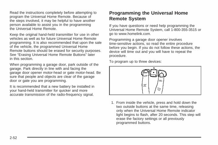
Read the instructions completely before attempting toprogram the Universal Home Remote. Because ofthe steps involved, it may be helpful to have anotherperson available to assist you in the programmingthe Universal Home Remote.
Keep the original hand-held transmitter for use in othervehicles as well as for future Universal Home Remoteprogramming. It is also recommended that upon the saleof the vehicle, the programmed Universal HomeRemote buttons should be erased for security purposes.See “Erasing Universal Home Remote Buttons” laterin this section.
When programming a garage door, park outside of thegarage. Park directly in line with and facing thegarage door opener motor-head or gate motor-head. Besure that people and objects are clear of the garagedoor or gate you are programming.
It is recommended that a new battery be installed inyour hand-held transmitter for quicker and moreaccurate transmission of the radio-frequency signal.
Programming the Universal HomeRemote SystemIf you have questions or need help programming theUniversal Home Remote System, call 1-800-355-3515 orgo to www.homelink.com.
Programming a garage door opener involvestime-sensitive actions, so read the entire procedurebefore you begin. If you do not follow these actions, thedevice will time out and you will have to repeat theprocedure.
To program up to three devices:
1. From inside the vehicle, press and hold down thetwo outside buttons at the same time, releasingonly when the Universal Home Remote indicatorlight begins to flash, after 20 seconds. This step willerase the factory settings or all previouslyprogrammed buttons.
2-52

Do not hold down the buttons for longer than30 seconds and do not repeat this step to programthe remaining two Universal Home Remotebuttons.
2. Hold the end of your hand-held transmitter about1 to 3 inches (3 to 8 cm) away from the UniversalHome Remote buttons while keeping the indicatorlight in view. The hand-held transmitter was suppliedby the manufacturer of your garage door openerreceiver (motor head unit).
3. At the same time, press and hold both the UniversalHome Remote button that you would like to use tocontrol the garage door and the hand-heldtransmitter button. Do not release the UniversalHome Remote button or the hand-held transmitterbutton until Step 4 has been completed.Some entry gates and garage door openers mayrequire you to substitute Step 3 with the procedurenoted in “Gate Operator and CanadianProgramming” later in this section.
4. The indicator light on the Universal Home Remotewill flash slowly at first and then rapidly afterUniversal Home Remote successfully receives thefrequency signal from the hand-held transmitter.Release both buttons.
5. Press and hold the newly-trained Universal HomeRemote button and observe the indicator light.If the indicator light stays on continuously,the programming is complete and your garage doorshould move when the Universal Home Remotebutton is pressed and released. You do not need tocontinue the programming Steps 6 through 8 andcan stop here.If the Universal Home Remote indicator light blinksrapidly for two seconds and then turns to aconstant light, continue with the programming Steps6 through 8.It may be helpful to have another person availableto assist with the remaining steps.
2-53

6. After Steps 1 through 5 have been completed,locate inside the garage the garage door openerreceiver (motor-head unit). Locate the “Learn”or “Smart” button. The name and color of the buttonmay vary by manufacturer.
7. Firmly press and release the “Learn” or “Smart”button. After you press this button, you will have30 seconds to complete Step 8.
8. Immediately return to the vehicle. Firmly press andhold the Universal Home Remote button, chosen inStep 3 to control the garage door, for two seconds,and then release it. If the garage door does notmove, press and hold the same button a second timefor two seconds, and then release it. Again, if thedoor does not move, press and hold the same buttona third time for two seconds, and then release.The Universal Home Remote should now activatethe garage door.
To program the remaining two Universal Home Remotebuttons, begin with Step 2 of “Programming theUniversal Home Remote System.” Do not repeat Step 1,as this will erase all previous programming from theUniversal Home Remote buttons.
2-54

Gate Operator and CanadianProgrammingIf you have questions or need help programming theUniversal Home Remote System, call 1-800-355-3515 orgo to www.homelink.com.
Canadian radio-frequency laws require transmittersignals to time out or quit after several seconds oftransmission. This may not be long enough for UniversalHome Remote to pick up the signal during programming.Similarly, some U.S. gate operators are manufacturedto time out in the same manner.
If you live in Canada, or you are having difficultyprogramming a gate operator or garage door opener byusing the “Programming Universal Home Remote”procedures, regardless of where you live, replace Step3 under “Programming Universal Home Remote”with the following:
Continue to press and hold the Universal Home Remotebutton while you press and release every two seconds(cycle) the hand-held transmitter button until thefrequency signal has been successfully accepted by theUniversal Home Remote. The Universal Home Remoteindicator light will flash slowly at first and then rapidly.Proceed with Step 4 under “Programming UniversalHome Remote” to complete.
Using Universal Home RemotePress and hold the appropriate Universal Home Remotebutton for at least half of a second. The indicator lightwill come on while the signal is being transmitted.
Erasing Universal Home RemoteButtonsErase the programmed buttons when you sell orterminate your lease.
To erase all programmed buttons on the UniversalHome Remote device:
1. Press and hold down the two outside buttons untilthe indicator light begins to flash, after 20 seconds.
2. Release both buttons.
2-55

Reprogramming a Single UniversalHome Remote ButtonTo reprogram any of the three Universal Home Remotebuttons, repeat the programming instructions earlierin this section, beginning with Step 2.
For help or information on the Universal Home RemoteSystem, call the customer assistance phone numberunder Customer Assistance Offices on page 7-5.
Storage AreasYour vehicle’s large carrying capacity can store manyitems. If the vehicle has an extended wheelbase, it cancarry even larger items. The floor pins that are usedto attach the seats, can be used to secure larger loads.
Glove BoxTo open, lift the handle up. Use the key to lock andunlock.
Cupholder(s)There are cupholders located below the centerinstrument panel switchbank. The cupholders have arubber liner that can be removed, so that larger cups canfit into the cupholders. You can also remove the linerto clean it.
To use the cupholders, pull the tray out. Push the trayback when not in use.
Your vehicle may be equipped with cupholders in thesecond row.
Overhead Console (Without Rail)If your vehicle has an overhead console without the railsystem, it has two reading lights, a courtesy light,and a switchbank. See Overhead Console Switchbankon page 3-21 for more information.
2-56

Overhead Console (With Rail)If your vehicle is equipped with an overhead console, itmay contain the following:
• Reading lamps. See Front Reading Lamps onpage 3-19 or Rear Reading Lamps on page 3-19.
• Switchbank. See Overhead Console Switchbank onpage 3-21.
• OnStar® System buttons. See OnStar® System onpage 2-47.
• Universal Home Remote buttons. See UniversalHome Remote System on page 2-51.
See your dealer to purchase additional items for the railsystem.
Storage BinYour vehicle may have a storage bin located on theoverhead rail that you can use for storage.
If your bin is equipped with the finger size latches dothe following:
1. Place the storage bin on to the rails in the desiredlocation.
2. Push firmly upward on the bin while supporting itwith one hand.
3. Push in on the latch and then rotate it 90 degrees.
2-57

4. Firmly press down making sure the latch is flat withthe ribs (A) on the storage bin.
5. Switch hands and repeat Steps 2 through 4 for thelatch on the opposite side of the storage bin.
6. Reverse these steps in order to remove thestorage bin.
If your bin is equipped with the hand size latches do thefollowing:
1. Place the storage bin on to the rails in the desiredlocation.
2. Push firmly upward on the bin while supporting itwith one hand.
3. The bin will snap into place.
4. To remove the bin, support the bin with one handwhile pulling each latch up and away from the bin.
The contents of the bin should never weigh more than1.5 lbs (0.7 kg).
Always make sure to close and latch the bin beforedriving.
2-58

Floor Console Storage AreaYour vehicle may have a storage compartment locatedon the front console below the front cupholders. Pullup and then forward on the handle to open the storagecompartment.
Folding Tray
Your vehicle may beequipped with foldingconvenience trays locatedbetween seats. To useeach tray lift up onthe handle located on itsfront end, while pullingup on the tray to lock it intoplace. There are fourcupholders on each tray.
Second Row Center ConsoleIf your vehicle has the second row center console, usethe following procedure to remove or install theconsole.
Removing the Center Console1. Locate the attachment lever in an opening on the
rear of the console
2. Pull the attachment lever upward to release theattachment hook.
3. Lift the console up to remove it from the vehicle.
2-59

Replacing the Center Console
{CAUTION:
A second row center console that is not lockedinto place properly can move around in acrash or sudden stop. People in the vehiclecould be injured. Be sure to lock the consoleinto place properly when installing it.
1. Position the second row center console above theforward floor attachments between the second rowbucket seats.For information on installing the seats, see RearSeat Operation on page 1-6.
2. Place the console’s front hooks onto the forwardfloor attachments.
3. Locate the attachment lever at the rear of theconsole and pull up.
4. Rock the rear attachment bracket onto the floorattachment and release the lever.
5. Pull up on the console to ensure the rearattachment hook is latched.
Luggage Carrier
{CAUTION:
If you try to carry something on top of yourvehicle that is longer or wider than the luggagecarrier — like paneling, plywood, a mattress andso forth — the wind can catch it as you drivealong. This can cause you to lose control. Whatyou are carrying could be violently torn off, andthis could cause you or other drivers to have acollision, and of course damage your vehicle.You may be able to carry something like thisinside. But, never carry something longer orwider than the luggage carrier on top of yourvehicle.
If you have the luggage carrier, you can load things ontop of your vehicle. Crossrails are not standard on thisvehicle and must be purchased at your dealer.
Notice: Loading cargo on the luggage carrier thatweighs more than 150 lbs (68 kg) or hangs over therear or sides of the vehicle may damage your vehicle.Load cargo so that it rests on the slats as far forwardas possible and against the side rails, making sure tofasten it securely.
2-60

Do not exceed the maximum vehicle capacity whenloading your vehicle. For more information on vehiclecapacity and loading, see Loading Your Vehicle onpage 4-21.
To prevent damage or loss of cargo as you are driving,check now and then to make sure the cargo is stillsecurely fastened.
Convenience Net (With RearConvenience Center)Your vehicle may have a convenience net. Theconvenience net is designed to help keep small loads,from falling out of the vehicle when the liftgate isopened. Install the convenience net at the rear of yourvehicle, inside the liftgate.
To use the convenience net, do the following:
1. Attach the upper loops to the posts on both sides ofthe liftgate opening. The label on the net should bein the upper left corner.
2. Attach the lower loops to the tabs at the rear edgeof the rear convenience center.
When not in use, it is recommended that you take downthe convenience net to extend the life of the net and tohelp retain its elasticity, and to keep the rear exit clear.
Convenience Net (Without RearConvenience Center)Your vehicle may have a convenience net. Theconvenience net is designed to help keep small loads,like grocery bags, from falling over. Install theconvenience net at the rear of your vehicle, inside theliftgate.
To use the convenience net, do the following:
1. Attach the upper loops to the posts on both sides ofthe liftgate opening. The label on the net should bein the upper left corner.
2. Attach the lower hooks to the metal rings onthe floor.
3. Once you have loaded items into the net, stretchthe higher side of the net up and over the top ofthe load to hold it firmly in place.
The convenience net has a maximum capacity of100 lbs (45 kg). It is not designed to hold larger, heavierloads. Store such loads on the floor of your vehicle,as far forward as you can.
When not in use, it is recommended that you take downthe convenience net to extend the life of the net and tohelp retain its elasticity, and to keep the rear exit clear.
2-61

Convenience Center
{CAUTION:
If any removable convenience item is notsecured properly, it can move around in acollision or sudden stop. People in the vehiclecould be injured. Be sure to secure any suchitem properly.
Your vehicle may have a convenience center. It providesextra storage space for the rear of the vehicle.
To open the convenience center, pull up on the doorlatch located on the front of the cover. The conveniencecenter cover has two automatic prop rods to hold itup and in place.
To close the convenience center cover, you must pullone of the prop rod linkages toward you while holdingonto the door latch and lower the conveniencecenter cover to close it.
Removing the Convenience Center1. Make sure that all items are off the convenience
center and that it is empty.
2. Turn the hand knob, located at the rear of theconvenience center, counterclockwise until theknob is loose.
3. Lift up on the hand knob, then grip and pull up onthe convenience center to remove it from thevehicle.
2-62

Replacing the Convenience Center1. Make sure the third row seat is properly installed in
the vehicle. See Third Row Seat on page 1-18 formore information. If the third row seat is not inthe vehicle with the convenience center, theconvenience center will not be locked into thecorrect position in the vehicle.
2. Make sure that the convenience center is emptyand closed.
3. Lift the convenience center up and into the rear ofthe vehicle.
4. Slide the convenience center in and align it to therear seat.
5. Press down on the front of the convenience centerso the center is aligned on the sill mountingbracket.
6. Turn the hand knob clockwise until it is tight.
7. Pull up on the convenience center to make sure itis locked into place.
The cover of the convenience center can be left in itsupright position while the vehicle is moving.
The convenience center and the third row seat bothhave a maximum weight capacity of 400 lbs (181.6 kg).
Notice: Overloading your vehicle maycause damage. Repairs would not be coveredby your warranty. Do not overload yourvehicle.
2-63

✍ NOTES
2-64

Instrument Panel Overview ...............................3-4Hazard Warning Flashers ................................3-6Other Warning Devices ...................................3-6Horn .............................................................3-6Tilt Wheel .....................................................3-6Turn Signal/Multifunction Lever .........................3-7Turn and Lane-Change Signals ........................3-7Headlamp High/Low-Beam Changer ..................3-8Flash-to-Pass .................................................3-8Windshield Wipers ..........................................3-9Windshield Washer .........................................3-9Rear Window Wiper/Washer ...........................3-10Cruise Control ..............................................3-10Exterior Lamps .............................................3-14Wiper Activated Headlamps ............................3-15Headlamps on Reminder ................................3-15Daytime Running Lamps (DRL)/Automatic
Headlamp System ......................................3-16Instrument Panel Brightness ...........................3-17Interior Lamps Control ...................................3-17
Dome Lamp .................................................3-18Entry Lighting ...............................................3-18Delayed Lighting ...........................................3-18Exit Lighting .................................................3-19Front Reading Lamps ....................................3-19Rear Reading Lamps ....................................3-19Cargo Lamp .................................................3-19Electric Power Management ...........................3-20Battery Run-Down Protection ..........................3-21Overhead Console Switchbank .......................3-21Accessory Power Outlet(s) .............................3-22Power Outlet 115 Volt Alternating Current ........3-23Cigarette Lighter ...........................................3-24
Climate Controls ............................................3-24Climate Control System .................................3-24Dual Climate Control System ..........................3-27Outlet Adjustment .........................................3-30Rear Climate Control System .........................3-30Passenger Compartment Air Filter ...................3-32
Section 3 Instrument Panel
3-1

Warning Lights, Gages, and Indicators ............3-34Instrument Panel Cluster ................................3-35Speedometer and Odometer ...........................3-36Trip Odometer ..............................................3-36Tachometer .................................................3-36Safety Belt Reminders ...................................3-36Airbag Readiness Light ..................................3-37Passenger Airbag Status Indicator ...................3-38Charging System Light ..................................3-40Brake System Warning Light ..........................3-41Antilock Brake System Warning Light ...............3-42Traction Control System (TCS) Warning Light ......3-42Engine Coolant Temperature Gage ..................3-43Tire Pressure Light .......................................3-43Malfunction Indicator Lamp .............................3-44Oil Pressure Light .........................................3-47Security Light ...............................................3-48Cruise Control Light ......................................3-48Highbeam On Light .......................................3-48Fuel Gage ...................................................3-49Low Fuel Warning Light .................................3-49
Driver Information Center (DIC) .......................3-50DIC Operation and Displays ...........................3-50DIC Compass (Uplevel Only) ..........................3-56DIC Warnings and Messages .........................3-58DIC Vehicle Personalization (Uplevel Only) .......3-76
Audio System(s) .............................................3-84Setting the Time ...........................................3-85Radio(s) (MP3) .............................................3-86Using an MP3 ..............................................3-98XM Radio Messages ...................................3-101Navigation/Radio System ..............................3-102Rear Seat Entertainment (RSE) System .........3-102Rear Seat Audio (RSA) ................................3-117Theft-Deterrent Feature ................................3-118Audio Steering Wheel Controls ......................3-119Radio Reception .........................................3-120Fixed Mast Antenna ....................................3-121XM™ Satellite Radio Antenna System ............3-121Chime Level Adjustment ...............................3-121
Section 3 Instrument Panel
3-2

✍ NOTES
3-3

Instrument Panel Overview
3-4

The main components of the instrument panel are the following:
A. Air Outlets. See Outlet Adjustment on page 3-30.B. Turn Signal/Multifunction Lever. See Turn
Signal/Multifunction Lever on page 3-7.C. Audio Steering Wheel Controls (If Equipped).
See Audio Steering Wheel Controls on page 3-119.D. Instrument Panel Cluster. See Instrument Panel
Cluster on page 3-35.E. Driver Information Center (DIC) Controls
(If Equipped). See Driver Information Center (DIC)on page 3-50.
F. Traction Control System Button (If Equipped).See Traction Control System (TCS) on page 4-6.
G. Hazard Warning Flasher Switch. See HazardWarning Flashers on page 3-6.
H. Passenger Airbag Status And Passenger SeatbeltReminder Indicator. See Passenger Airbag StatusIndicator on page 3-38 and Safety Belt Reminderson page 3-36.
I. Audio System. See Audio System(s) on page 3-84.J. Exterior Lamps Control. See Exterior Lamps on
page 3-14.K. Interior Lamps Control. See Interior Lamps Control
on page 3-17. Instrument Panel Brightness Control.See Instrument Panel Brightness on page 3-17.
L. Hood Release. See Hood Release on page 5-11.M. Parking Brake. See Parking Brake on page 2-38.N. Horn. See Horn on page 3-6.O. Cruise Controls (If Equipped). See Cruise Control on
page 3-10.P. Climate Controls. See Climate Control System on
page 3-24. Dual Climate Controls. See Dual ClimateControl System on page 3-27.
Q. Heated Seat Controls (If Equipped). See HeatedSeats on page 1-3.
R. Glove Box. See Glove Box on page 2-56.
3-5

Hazard Warning FlashersThe hazard warning flashers let you warn the police andothers that you have a problem. The front and rearturn signal lamps will flash on and off.
The hazard warningflasher button is locatedtowards the center ofthe instrument panel.
Press the button to make the front and rear turn signallamps flash on and off. Press the button again toturn the flashers off.
While the hazard warning flashers are on, the turnsignals do not work.
The hazard warning flashers work no matter whatposition the key is in, and even if the key is not inthe ignition switch.
Other Warning DevicesIf you carry reflective triangles, you can set them up atthe side of the road about 300 feet (100 m) behindyour vehicle.
HornPress near or on the horn symbols on the steeringwheel pad to sound the horn.
Tilt WheelA tilt wheel lets you adjust the steering wheel beforeyou drive. You can raise the steering wheel to thehighest level to give your legs more room when youenter and exit the vehicle.
The lever that lets you tilt the steering wheel is locatedon the left side of the steering column.
To tilt the wheel, hold thewheel and pull the lever.Then move the wheelto a comfortable positionand release the leverto lock the wheel in place.
3-6

Turn Signal/Multifunction Lever
The lever on the left side of the steering columnincludes the following:
• G Turn and Lane Change Signals. See Turn andLane-Change Signals on page 3-7.
• 53 Headlamp High/Low-Beam Changer.See Headlamp High/Low-Beam Changer onpage 3-8.
• Flash-to-Pass. See Flash-to-Pass on page 3-8.
• N Windshield Wipers. See Windshield Wipers onpage 3-9.
• L Windshield Washer. See Windshield Washeron page 3-9.
• Z Rear Window Wiper. See Windshield Washeron page 3-9.
• = Rear Window Washer. See Windshield Washeron page 3-9.
For information on the headlamps, see Exterior Lampson page 3-14.
Turn and Lane-Change SignalsThe turn signal has two upward (for right) andtwo downward (for left) positions. These positionsallow you to signal a turn or a lane change.
To signal a turn, move the lever all the way up ordown. When the turn is finished, the lever will returnautomatically.
An arrow on the instrumentpanel cluster will flashin the direction of theturn or lane change.
3-7

To signal a lane change, just raise or lower the leveruntil the arrow starts to flash. Hold it there until youcomplete your lane change. The lever will return byitself when you release it.
As you signal a turn or a lane change, if the arrowflashes faster than normal, a signal bulb may be burnedout and other drivers will not see your turn signal.
If a bulb is burned out, replace it to help avoid anaccident. If the arrows do not go on at all when yousignal a turn, check for burned-out bulbs and check thefuse. See Bulb Replacement on page 5-42 and Fusesand Circuit Breakers on page 5-100.
If you have a trailer towing option with added wiring forthe trailer lamps, the signal indicator will flash at a normalrate even if a turn signal bulb is burned out. Check thefront and rear turn signal lamps regularly to make surethey are working.
Turn Signal On ChimeIf either turn signal is left on for more than3/4 mile (1.2 km), a chime will sound to let the driverknow to turn it off. If you need to leave the signal on formore than 3/4 mile (1.2 km), turn off the signal and thenturn it back on.
Headlamp High/Low-Beam ChangerTo change the headlamps from low beam to high beam,push the turn signal/multifunction lever away from you.
When the high beams areon, this light will appearon the instrumentpanel cluster.
To change the headlamps from high beam to low beam,pull the turn signal/multifunction lever toward you.
Flash-to-PassWhen the headlamps are off, pull the lever toward youto momentarily turn on the high beams. This will signalthat you are going to pass. When you release the lever,they will turn off.
3-8

Windshield WipersYou control the windshield wipers by turning the bandwith the wiper symbol on it.
8 (Mist): For a single wiping cycle, turn the band tomist. Hold it there until the wipers start. Then let go.The wipers will stop after one wipe. If you wantmore wipes, hold the band on mist longer.
9 (Off): To stop the wipers, move the band to off.
N (Delay): You can set the wiper speed for a longor short delay between wipes. This can be very useful inlight rain or snow. Turn the band to choose the delaytime. The closer to the top of the lever, the shorterthe delay.
6 (Low Speed): For steady wiping at low speed,turn the band away from you to the first solid bandpast the delay settings. For high-speed wiping, turn theband further, to the second solid band past the delaysettings. To stop the wipers, move the band to off.
1 (High Speed): For high-speed wiping, turnthe band further, to the second solid band past thedelay settings.
Be sure to clear ice and snow from the wiper bladesbefore using them. If they are frozen to the windshield,carefully loosen or thaw them. If your blades dobecome worn or damaged, get new blades or bladeinserts.
Windshield Washer
LQ (Windshield Washer): Press and hold thewindshield washer paddle with this symbol on it to washyour windshield. The washers and wipers will operate.
When you release the paddle, the washers will stop,and the wipers will continue to operate for two cycles,unless your wipers had already been on. In thatcase, the wipers will resume the wiper speed youhad selected earlier.
{CAUTION:
In freezing weather, do not use your washeruntil the windshield is warmed. Otherwise thewasher fluid can form ice on the windshield,blocking your vision.
3-9

Rear Window Wiper/Washer
{CAUTION:
In freezing weather, do not use your washeruntil the windshield is warmed. Otherwise thewasher fluid can form ice on the windshield,blocking your vision.
If your vehicle has the rearwindow washer/wiper, thecontrols are located on theend of the turn signal/multifunction lever.
9 (Off): Move the lever to this position to turn therear washers/wipers off.
Z (Rear Wiper): Move the lever to this position toturn the rear wipers on.
= (Rear Washer/Wiper): Move the lever to thisposition to wash and wipe the rear window.
The rear window washer uses the same fluid bottleas the windshield washer. However, the rear windowwasher will run out of fluid before the windshield washer.If you can wash your windshield but not your rearwindow, check the fluid level.
Cruise Control
{CAUTION:
Cruise control can be dangerous where youcannot drive safely at a steady speed. So, donot use your cruise control on winding roadsor in heavy traffic.
Cruise control can be dangerous on slipperyroads. On such roads, fast changes in tiretraction can cause excessive wheel slip, andyou could lose control. Do not use cruisecontrol on slippery roads.
3-10

If your vehicle has cruisecontrol, the lever is locatedbelow the windshieldwiper control on the rightside of the steering wheel.
Q RES + (Resume/Accelerate): Push the lever upto resume the cruise control speed, or to acceleratewhen passing another vehicle.
J (CRUISE CONTROL) ON/OFF q: Press thebutton on the end of the lever to turn the cruise controlon. Press it again to turn cruise control off.
R SET — (Set/Coast/Decelerate): Push the leverdown to set the cruise speed. If the cruise speedis already set this position can be used to coastor decelerate from a higher speed.
CANCEL R: Pull the lever to cancel the cruisecontrol speed.
Cruise control allows a speed of approximately25 mph (40 km/h) or more to be maintained withoutkeeping your foot on the accelerator. This is helpfulon long trips. Cruise control does not work at speedsbelow about 25 mph (40 km/h).
When the brakes are applied, the cruise controlshuts off.
If the vehicle is in cruise control and the TractionControl System (TCS) begins to limit wheel spin,the cruise control will automatically disengage. SeeTraction Control System (TCS) on page 4-6. When roadconditions allow, the cruise control can be used again.
3-11

Setting Cruise Control
{CAUTION:
If you leave your cruise control on when youare not using cruise, you might hit a buttonand go into cruise when you do not want to.You could be startled and even lose control.Keep the cruise control switch off until youwant to use cruise control.
1. Push the button at the end of the cruise controllever to turn the cruise control on.
2. Accelerate to the desired speed.
3. Push down on the cruise control lever and releaseit. This will set the speed in cruise control.
4. Remove your foot from the accelerator pedal.
This symbol will appearon the instrument panelcluster when the cruisecontrol is set.
This symbol will disappear when the brakes are appliedor the cruise control is cancelled. It will reappearwhen the set cruise speed is resumed.
Resuming a Set SpeedIf the cruise control is set at a desired speed and thenthe brakes are applied, the cruise control shuts off.But the cruise control does not need to be reset.
Once the vehicle is traveling approximately25 mph (40 km/h) or more, the cruise control lever canbe pushed upward toward the plus (resume/accelerate)position to return to the preset cruise speed.
The vehicle will return to and stay at the preset cruisespeed. If the cruise control lever is pushed up andheld toward the plus (resume/accelerate) position, thevehicle speed will increase until the lever is releasedor the brakes are applied. Do not continue to holdthe lever in the plus (resume/accelerate) position,unless a faster speed is desired.
3-12

Increasing Speed While Using CruiseControlThere are two ways to go to a higher speed:
• Use the accelerator pedal to get to the higher speed.Push up on the cruise control lever toward the plus(resume/accelerate) position, then release the leverand take your foot off the accelerator pedal. Thevehicle will now cruise at the higher speed.
• Push up and hold the cruise control lever towardthe plus (resume/accelerate) position until thevehicle reaches the desired speed. Then releasethe cruise control lever. To increase the vehicle’sspeed in very small amounts, push up briefly on thecruise control lever and release it. Each time thisis done, the vehicle will speed up approximatelyone mph (1.6 km/h).
The acceleration feature will only work after the cruisecontrol speed has been set by pushing the cruise controllever down to the set position.
Reducing Speed While Using CruiseControlThere are two ways to reduce the vehicle’s speed whileusing cruise control:
• Push the cruise control lever downward toward theminus (set/coast/decelerate) position until a lowerspeed is reached, then release it.
• To slow down in very small amounts, push thecruise control lever downward toward the minus(set/coast/decelerate) position briefly. Each time thisis done, the vehicle will slow down approximatelyone mph (1.6 km/h).
Passing Another Vehicle While UsingCruise ControlUse the accelerator pedal to increase the vehicle’sspeed. When you take your foot off the pedal, thevehicle will slow down to the cruise control speedset earlier.
3-13

Using Cruise Control on HillsHow well the cruise control will work on hills dependsupon the vehicle’s speed, its load, and the steepnessof the hills. When going up steep hills, the acceleratorpedal might have to be used in order to maintainthe vehicle’s speed. When going downhill, the brakesmight have to be applied, or the transaxle might haveto be shifted to a lower gear to keep the vehicle’s speeddown. Doing either of these things will take the vehicleout of cruise. It may be better not to use the cruisecontrol if the brakes constantly have to be applied,or the vehicle continuously needs to be shifted to alower gear.
Cancelling Cruise ControlTo cancel a cruise control session, pull the cruisecontrol lever forward, or step lightly on the brake pedal.
Doing either of these things will only end the currentcruise control session, but the set speed will be retainedin memory.
Push the button at the end of the cruise control lever toturn the system off.
Erasing Speed MemoryWhen the cruise control or the ignition is turned off,the cruise control set speed memory is erased.
Exterior Lamps
The control to the left of thesteering column operatesthe exterior lamps.
9 (Off): Turn the control to this position to toggle offall lamps. This is a momentary control that will springback to AUTO when released.
This momentary control will turn the automaticheadlamps and/or the Daytime Running Lamps on andoff for U.S. vehicles. For vehicles first sold in Canada,this is only true when the transaxle is in PARK (P).
3-14

AUTO (Automatic): Turn the control to this position toset your headlamps in automatic mode. AUTO mode,if enabled, will turn the exterior lamps on and offautomatically depending on how much light isavailable outside the vehicle.
Due to the momentary switch design, your automaticlights may be disabled even if the control is in theAUTO position.
; (Parking Lamps): Turn the control to this position toturn on the parking lamps together with the following:
• Taillamps
• Instrument Panel Lights
5 (Headlamps): Turn the control to this position toturn on the headlamps, together with the previouslylisted lamps and lights.
Wiper Activated HeadlampsThis feature, if equipped, will automatically activatethe headlamps and parking lamps after the windshieldwipers have been in use for about 30 seconds and whenall of the following conditions are met.
• The exterior lamp control is in AUTO.
• The headlamps have not already been activated byautomatic lighting.
• The automatic lighting feature has not beendisabled using the exterior lamp control.
See Exterior Lamps on page 3-14 for additionalinformation.
If the wipers are activated for over 30 seconds and theexterior lamp control is in the parking lamps position,or the automatic lighting feature has been disabled usingthe exterior lamp control, a HEADLAMPS SUGGESTEDmessage will appear on the Driver Information Center,if equipped.
Headlamps on ReminderIf you turn the ignition to LOCK while leaving the lampson, you will hear a warning chime once the driver’sdoor is opened.
3-15

Daytime Running Lamps (DRL)/Automatic Headlamp SystemDaytime Running Lamps (DRL) can make it easierfor others to see the front of your vehicle during the day.DRL can be helpful in many different driving conditions,but they can be especially helpful in the short periodsafter dawn and before sunset. Fully functional DaytimeRunning Lamps are required on all vehicles first soldin Canada.
A light sensor on top of the instrument panel makesthe DRL work, so be sure it is not covered. TheDRL system will make front parking and turn signallamps come on in daylight when the following conditionsare met:
• The ignition is on.
• The exterior lamps control is off.
When the DRL are on, only your front turn signal lampswill be on. Your instrument panel will not be lit up.
When it is dark enough outside, the exterior lampswill come on automatically. When it is bright enoughoutside, the exterior lamps will turn off and the DRL willturn on. Of course, you may still turn on the headlampsany time you need to.
If you start your vehicle in a dark garage, the automaticheadlamp system will come on immediately. Once youleave the garage, it will take approximately 30 secondsfor the automatic headlamp system to change to DRL if itis light outside. During that delay, your instrument panelcluster may not be as bright as usual. Make sure yourinstrument panel brightness control is in the full brightposition. See Instrument Panel Brightness on page 3-17.
To idle your vehicle with the DRL and automaticheadlamps off, toggle the exterior lamp control tooff after starting the vehicle.
As with any vehicle, you should turn on the regularheadlamp system when you need it.
3-16

Instrument Panel Brightness
The knob to adjust theinstrument panel brightnessis located in the center ofthe interior lamp controls.
Turn the knob clockwise to brighten the lights andcounterclockwise to dim them.
Interior Lamps Control
The interior lamp control islocated to the right of theexterior lamp controls onthe instrument panel to theleft of the steering column.
R (Interior Lamp Override): Turn the outer knob tothis position to have your interior lamps remain offwhile any door is open.
1 (Door): Turn the outer knob to this position toturn the interior lamps on while any door is open andwhen the ignition key is removed from the ignition.
+ (Interior Lamps): Turn the outer knob to thisposition to turn the interior lamps on.
Turn the inner knob to adjust the instrument panelbrightness, described earlier in this section.
3-17

Dome LampThe dome lamp is located in the headliner and hastwo buttons to manually turn it on or off. The dome lampwill come on each time you open a door, unless youturn on the interior lamps override feature. See InteriorLamps Control on page 3-17.
Entry LightingWith entry lighting, the interior of your vehicle isilluminated so that you can see inside before you enteryour vehicle. The lamps will come on for 20 secondsif you unlock your door using your key or the remotekeyless entry transmitter and the ignition is in LOCK.After 20 seconds have passed, the interior lampswill slowly fade out. The lamps will turn off beforethe 20 seconds if you do one of the following:
• Lock all the doors using the key.
• Press lock on the power door lock switch.
• Press lock on the remote keyless entry transmitter.
When any door is opened, entry lighting is cancelled.The interior lamps will stay on while any door orthe liftgate is open, and slowly fade out when alldoors and the liftgate are closed.
The interior lamps may stay on for up to 25 secondsafter all doors have been closed if they have not beenlocked. See Delayed Lighting on page 3-18.
To turn the entry lighting feature off or on, see DICVehicle Personalization (Uplevel Only) on page 3-76.
Delayed LightingThe delayed lighting feature will continue to illuminatethe interior for 20 seconds after all doors have beenclosed, so that you can find your ignition and buckleyour safety belt at night. Delayed lighting will not occurwhile the ignition is in RUN or ACCESSORY. After20 seconds have passed, the interior lamps will slowlyfade out. The lamps will fade out before the 20 secondshave passed if you do one of the following:
• Turn the ignition to RUN or ACCESSORY.
• Lock all doors using the remote keyless entrytransmitter.
• Lock all doors using the power door lock switch orthe key.
To turn the delayed lighting feature off or on, see DICVehicle Personalization (Uplevel Only) on page 3-76.
3-18

Exit LightingWith exit lighting, the interior lamps will come on forabout 25 seconds whenever you remove the key fromthe ignition. If you turn the ignition key to RUN orACCESSORY, the lamps will fade out. The lampswill also fade out if you lock the doors with the powerdoor lock switch or the remote keyless entry transmitter.
When any door is opened, exit lighting is cancelled.The interior lamps will stay on while any door orthe liftgate is open, and slowly fade out when alldoors and the liftgate are closed.
The interior lamps may stay on for up to 20 secondsafter all doors have been closed if they have not beenlocked. See Delayed Lighting on page 3-18.
To turn the exit lighting feature off or on, see DICVehicle Personalization (Uplevel Only) on page 3-76.
Front Reading LampsThere are two reading lamps and one courtesy lampin the overhead console. To turn either reading lamp onor off, press the lens of the lamp. The courtesy lampwill come on each time you open a door, unless youturn on the interior lamps override feature. See InteriorLamps Control on page 3-17.
Rear Reading LampsThere are two reading lamps in the third row headliner.To turn either reading lamp on or off, press the lensof the lamp.
There may also be a reading lamp in the second row,integrated with the dome lamp. To turn the secondrow reading lamp on or off, press the button next tothe lamp lens.
Cargo LampThe cargo lamp is located in the rear of your vehicle,above the liftgate opening, and does not have a switch.The cargo lamp will come on each time you open adoor, unless you turn on the interior lamps override.See Interior Lamps Control on page 3-17.
3-19

Electric Power ManagementThe vehicle has Electric Power Management (EPM)that estimates the battery’s temperature and stateof charge. It then adjusts the voltage for bestperformance and extended life of the battery.
When the battery’s state of charge is low, the voltage israised slightly to quickly put the charge back in. Whenthe state of charge is high, the voltage is lowered slightlyto prevent overcharging. If the vehicle has a voltmetergage or a voltage display on the Driver InformationCenter (DIC), you may see the voltage move upor down. This is normal. If there is a problem,an alert will be displayed.
The battery can be discharged at idle if the electricalloads are very high. This is true for all vehicles.This is because the generator (alternator) maynot be spinning fast enough at idle to produce allthe power that is needed for very high electrical loads.
A high electrical load occurs when several of thefollowing loads are on: headlamps, high beams, foglamps, rear window defogger, climate control fan athigh speed, heated seats, engine cooling fans, trailerloads, and loads plugged into accessory power outlets.
EPM works to prevent excessive discharge of thebattery. It does this by balancing the generator’s outputand the vehicle’s electrical needs. It can increase engineidle speed to generate more power, whenever needed.It can temporarily reduce the power demands of someaccessories.
Normally, these actions occur in steps or levels, withoutbeing noticeable. In rare cases at the highest levels ofcorrective action, this action may be noticeable to thedriver. If so, a Driver Information Center (DIC) messagemight be displayed, such as Battery Saver Active orService Battery Charging System. If this message isdisplayed, it is recommended that the driver reduce theelectrical loads as much as possible. See DIC Warningsand Messages on page 3-58.
3-20

Battery Run-Down ProtectionYour vehicle has a feature to help prevent you fromdraining the battery, in case you accidentally leave theinterior lamps on. If you leave any interior lamps onwhile the ignition is in lock or off, they will automaticallyturn off after 10 minutes. The lamps will not comeback on again until you do one of the following:
• Turn the ignition to RUN or ACCESSORY
• Open a closed door, or close and reopen a door.
• Turn the interior lamps on if they are in the door oroverride position.
• Turn the interior lamps to the door or overrideposition and then to on again if the interiorlamp control is in the on position.
If your vehicle has less than 15 miles (25 km) on theodometer, the battery saver will turn off the lamps afteronly three minutes.
Overhead Console Switchbank
The overhead console switchbank is located in theoverhead console. This switchbank may includethe following:
• Power Sliding Door(s)/Override Switch(es).See Power Sliding Door (PSD) on page 2-16.
• Power Rear Quarter Windows. See Power RearQuarter Windows on page 2-26.
• Ultrasonic Rear Parking Assist (URPA) DisableSwitch. See Ultrasonic Rear Parking Assist (URPA)on page 2-44.
If your vehicle does not have some of these options,there will be a blank.
3-21

Accessory Power Outlet(s)The accessory power outlets can be used to plug inelectrical equipment such as a cellular telephone orCB radio.
Your vehicle may have two accessory power outlets.There may be one outlet located below the climatecontrols on the instrument panel and one outlet locatedin the rear compartment on the driver’s side.
Pull the cover down to use the accessory power outlet.When not in use, keep the cover on.
To remove the rear accessory power outlet cover, pullthe tab on the cover and pull it off. To put the cover backon, line up the tabs at the back of the cover and putthe cover in place. Push down the tab to securethe cover. When not in use, always cover the rearaccessory power outlet with the protective cap.
Notice: Leaving electrical equipment on forextended periods will drain the battery. Alwaysunplug electrical equipment when not in use and donot plug in equipment that exceeds the maximumamperage rating of 20 amperes.
Certain electrical accessories may not be compatible withthe accessory power outlet and could result in blownvehicle or adapter fuses. If you experience a problem seeyour dealer for additional information on accessory poweroutlets.
Notice: Adding any electrical equipment to yourvehicle may damage it or keep other componentsfrom working as they should. The repairs would notbe covered by your warranty. Do not use equipmentexceeding maximum amperage rating of 20 amperes.Check with your dealer/retailer before addingelectrical equipment.
When adding electrical equipment, be sure to followthe proper installation instructions included withthe equipment.
Notice: Improper use of the power outlet can causedamage not covered by your warranty. Do nothang any type of accessory or accessory bracketfrom the plug because the power outlets aredesigned for accessory power plugs only.
3-22

Power Outlet 115 Volt AlternatingCurrentYour vehicle may have a power outlet that can be usedto plug in electrical equipment that uses a maximumlimit of 150 watts.
The power outlet is locatedbehind the third row seatson the passenger’s siderear quarter trim panel.
An indicator light on the outlet turns on to show it is inuse. The light comes on when the ignition is in ON/RUNand equipment requiring less than 150 watts is pluggedinto the outlet, and no system fault is detected.
The indicator light does not come on when the ignitionis in LOCK/OFF or if no equipment is plugged intothe outlet.
If you try to connect equipment using more than150 watts or a system fault is detected, a protectioncircuit shuts off the power supply and the indicator lightturns off. To reset the circuit, unplug the item and plug itback in or turn the Remote Accessory Power (RAP) offand then back on. See Retained Accessory Power (RAP)on page 2-32. The power restarts when equipment using150 watts or less is plugged into the outlet and a systemfault is not detected.
The power outlet is not designed for the followingelectrical equipment and may not work properly ifthese items are plugged into the power outlet:
• Equipment with high initial peak wattage suchas: compressor-driven refrigerators and electricpower tools.
• Other equipment requiring an extremely stablepower supply such as: microcomputer-controlledelectric blankets, touch sensor lamps, etc.
3-23

Cigarette LighterYour vehicle may have a cigarette lighter. To use thelighter, located on the instrument panel below theclimate controls, push it in all the way and let go.When it is ready, it will pop back out by itself.
Notice: Holding a cigarette lighter in while it isheating does not let the lighter back away fromthe heating element when it is hot. Damage fromoverheating can occur to the lighter or heatingelement, or a fuse could be blown. Do not holda cigarette lighter in while it is heating.
Notice: If you put papers, pins, or other flammableitems in the ashtray, hot cigarettes or other smokingmaterials could ignite them and possibly damageyour vehicle. Never put flammable items in theashtray.
Climate Controls
Climate Control SystemWith this system you can control the heating, coolingand ventilation for your vehicle.
3-24

OperationTurn the right knob clockwise or counterclockwise todirect the airflow inside of your vehicle.
To change the current mode, select one of the following:
H (Vent): This mode directs air to the instrumentpanel outlets.
) (Bi-Level): This mode directs half of the air to theinstrument panel outlets, then directs the remainingair to the floor outlets. Cooler air is directed to theupper outlets and warmer air to the floor outlets.
6 (Floor): This mode directs most of the air to thefloor outlets. Use this mode to send air to the rear ofthe vehicle. Keep the area under the front seats freeof objects that could obstruct airflow to the rear ofthe vehicle.
The right knob can also be used to select defog ordefrost mode. For more information, see “Defoggingand Defrosting” later in this section.
Outside Air: This mode will be automatically selectedwhen your vehicle is in any mode except maximumair conditioning.
A (Fan): Turn the left knob clockwise orcounterclockwise to increase or decrease the fan speed.Turn the knob to 0 to turn off the fan. The fan mustbe turned on for the air conditioning compressorto operate.
Temperature Control: Turn the center knob clockwiseor counterclockwise to increase or decrease the airtemperature inside your vehicle.
# (Air Conditioning): Press this button to turn theair-conditioning system on or off. When it is pressed,an indicator light in the button will come on to letyou know that air conditioning is activated.
You may notice a slight change in engine performancewhen the air conditioning compressor shuts off andturns on again. This is normal. The system is designedto make adjustments to help with fuel economy whilestill maintaining the selected temperature.
On hot days, open the windows to let hot inside airescape; then close them. This helps to reduce the timeit takes for your vehicle to cool down. It also helpsthe system to operate more efficiently.
3-25

The air conditioning system removes moisture from theair, so you may sometimes notice a small amount ofwater dripping underneath your vehicle while idlingor after turning off the engine. This is normal.
@ MAX A/C (Maximum Air Conditioning): Turn theright knob to this position for maximum air conditioning.This will select air conditioning and recirculation formaximum cooling of your vehicle. This mode directsair to the instrument panel outlets.
Recirculation: This mode keeps outside air fromcoming in the vehicle. It can be used to prevent outsideair and odors from entering your vehicle or help heator cool the air inside your vehicle more quickly.This mode will automatically be selected whenyou select maximum air conditioning.
( (Heated Seats): Press this button to turn on theheated seats. The button on the left controls the driver’sseat and the button on the right controls the passenger’sseat. See Heated Seats on page 1-3 for additionalinformation.
Defogging and DefrostingFog on the inside of windows is a result of high humidity,or moisture, condensing on the cool window glass.This can be minimized if the climate control system isused properly. There are two modes to clear fog or frostfrom your windshield. Use the defog mode to clear thewindows of fog or moisture and warm the passengers.Use the defrost mode to remove fog or frost from thewindshield more quickly.
Turn the right knob to select the defog or defrost mode.
- (Defog): This mode directs air to the windshieldand the floor outlets. When you select this mode,the system runs the air-conditioning compressorunless the outside temperature is at or below freezing.The recirculation mode cannot be selected while inthe defog mode.
0 (Defrost): This mode directs most of the air to thewindshield and the side window outlets, with some airdirected to the floor outlets. In this mode, the systemwill automatically run the air-conditioning compressor,unless the outside temperature is at or below freezing.Recirculation cannot be selected while in thedefrost mode.
Do not drive the vehicle until all the windows are clear.
3-26

Rear Window DefoggerIf your vehicle has a rear window defogger a warminggrid is used to remove fog from the rear window.
< REAR: Press this button to turn the rear windowdefogger on or off. An indicator light in the buttonwill come on to let you know that the rear windowdefogger is activated.
The rear window defogger will turn off about 15 minutesafter the button is pressed. If turned on again, thedefogger will only run for about five minutes beforeturning off. The defogger can also be turned off bypressing the button again or by turning off the engine.
Notice: Do not use anything sharp on the insideof the rear window. If you do, you could cut ordamage the warming grid, and the repairs wouldnot be covered by your warranty. Do not attacha temporary vehicle license, tape, a decal oranything similar to the defogger grid.
Dual Climate Control SystemYour vehicle may have a dual climate control system.With this system you can control the heating, cooling,and ventilation for your vehicle.
Operation
9 (Fan): Turn the left knob clockwise orcounterclockwise to increase or decrease the fan speed.Turn the knob to 0 to turn off the fan. The fan must beturned on for the air conditioning compressor to operate.
3-27

Temperature Control: Use the driver’s andpassenger’s levers to increase or decrease the airtemperature inside your vehicle.
Turn the right knob clockwise or counterclockwise todirect the airflow inside of your vehicle.
To change the current mode, select one of the following:
@ MAX A/C (Maximum Air Conditioning):Turn the right knob to this position for maximum airconditioning. This will select air conditioning andrecirculation for maximum cooling of your vehicle.
Recirculation: This mode keeps outside air fromcoming in the vehicle. It can be used to prevent outsideair and odors from entering your vehicle or help heator cool the air inside your vehicle more quickly.This mode will automatically be selected whenmaximum air conditioning is selected.
H (Vent): This mode directs air to the instrumentpanel outlets.
) (Bi-Level): This mode directs half of the air to theinstrument panel outlets, then directs the remainingair to the floor outlets. Cooler air is directed to theupper outlets and warmer air to the floor outlets.
6 (Floor): This mode directs most of the air to thefloor outlets. Use this mode to send air to the rear of thevehicle. Keep the area under the front seats free ofobjects that could obstruct airflow to the rear ofthe vehicle.
Outside Air: This mode is automatically selectedwhen your vehicle is in any mode except maximumair conditioning.
The right knob can also be used to select defog ordefrost mode. For more information, see “Defoggingand Defrosting” later in this section.
# (Air Conditioning): Press this button to turn the airconditioning system on or off. When it is pressed, anindicator light in the button will come on to let you knowthat air conditioning is activated.
You may notice a slight change in engine performancewhen the air conditioning compressor shuts off andturns on again. This is normal. The system is designedto make adjustments to help with fuel economy whilestill maintaining the selected temperature.
On hot days, open the windows to let hot inside airescape; then close them and switch to maximumair conditioning mode. This helps to reduce the timeit takes for your vehicle to cool down. It also helps thesystem to operate more efficiently.
3-28

The air conditioning system removes moisture from theair, so you may sometimes notice a small amount ofwater dripping underneath your vehicle while idlingor after turning off the engine. This is normal.
( (Heated Seats): Press this button to turn on theheated seats. The button on the left controls the driver’sseat and the button on the right controls the passenger’sseat. See Heated Seats on page 1-3 for additionalinformation.
Defogging and DefrostingFog on the inside of windows is a result of high humidity,or moisture, condensing on the cool window glass.This can be minimized if the climate control system isused properly. There are two modes to clear fog or frostfrom your windshield. Use the defog mode to clear thewindows of fog or moisture and warm the passengers.Use the defrost mode to remove fog or frost from thewindshield more quickly.
Turn the right knob to select the defog or defrost mode.
- (Defog): This mode directs air to the windshieldand the floor outlets. When this mode is selected, thesystem runs the air conditioning compressor unlessthe outside temperature is at or below freezing.
The recirculation mode cannot be selected while in thedefog mode.
0 (Defrost): This mode directs most of the air to thewindshield and the side window outlets, with someair directed to the floor outlets. In this mode, the systemwill automatically run the air conditioning compressor,unless the outside temperature is at or below freezing.
Recirculation cannot be selected while in thedefrost mode.
Do not drive the vehicle until all the windows are clear.
Rear Window DefoggerThe rear window defogger uses a warming grid toremove fog from the rear window.
< (Rear Window Defogger): Press this button toturn the rear window defogger on or off. An indicatorlight in the button will come on to let you know that therear window defogger is activated.
The rear window defogger will turn off about 15 minutesafter the button is pressed. If turned on again, thedefogger will only run for about five minutes beforeturning off. The defogger can also be turned off bypressing the button again or by turning off the engine.
Notice: Do not use anything sharp on the inside ofthe rear window. If you do, you could cut or damagethe warming grid, and the repairs would not becovered by your warranty. Do not attach a temporaryvehicle license, tape, a decal or anything similar tothe defogger grid.
3-29

Outlet AdjustmentUse the louvers located on the air outlets to change thedirection of the airflow.
Use the thumbwheels on the driver side and passengerside air outlets to open or close the airflow fromthese outlets.
Operation Tips• Clear away any ice, snow, or leaves from the air
inlets at the base of the vehicle that could blockthe flow of air into your vehicle.
• Do not use any non-GM approved hood deflectorsthat could adversely affect the performance of thesystem.
• Keep the path under the front seats clear of objectsto help circulate the air inside of your vehicle moreeffectively.
Rear Climate Control SystemYour vehicle may have a rear climate control systemthat lets the driver adjust the fan speed for the rearseating area. This system works with the main climatecontrol system.
This lever used to adjust the fan speed for the rear seatpassengers is located below the main climate controlsystem.
A (Fan): Slide the lever to 1, 2, or 3 to increase ordecrease airflow to the rear seating area. Slide the fanknob to 0 to turn the fan off.
AUX (Auxiliary): Slide the lever to AUX to let therear passengers adjust the temperature and airflowto the rear seating area.
Your vehicle may also have a rear climate controlsystem that lets the rear passengers adjust thetemperature and fan speed for the rear seating area.
3-30

When the front climate control is in AUX and the rearclimate control fan or temperature button is pressed, thedisplay will show the same airflow modes as the frontclimate control system. See Dual Climate ControlSystem on page 3-27.
The front control must be in the AUX position to enableadjustment of the temperature and fan speed on therear control system. If it is not in AUX, pressing thefan or temperature button on the rear climate controlwill show a DISABLED message on the Rear SeatEntertainment (RSE) system display.
qg (Decrease Setting): Press this button todecrease the fan or temperature setting while arrowsare displayed.
rl (Increase Setting): Press this button to increasethe fan or temperature setting while arrows are displayed.
9 (Fan) b (Temperature): Press this button onceto enable adjustment of the fan speed. The currentfan speed setting and arrows are highlighted onthe display screen. Press either the left or the rightarrow button to increase or decrease fan speed.The on screen display disappears after a few seconds.
Press this button twice to enable temperatureadjustment. After pressing this button, the currenttemperature settings are highlighted and appearin the on screen display. The arrows indicate thatto increase or decrease temperature, press eitherthe left or right arrow button. The on screen displaydisappears after a few seconds.
Press this button a third time to turn off the on screendisplay.
QR: Press the up and down arrows to togglebetween the fan and temperature settings.
3-31

Rear Air OutletsThe outlet behind the driver side rear seat is for the coldair return. Be sure to keep it free from obstructions.Also, keep the area around the base of the centerinstrument panel console, between and under the frontseats, free of objects that could also obstruct airflowto the rear seating area.
For more information on how to use the main climatecontrol system, see Dual Climate Control Systemon page 3-27. For information on ventilation,see Outlet Adjustment on page 3-30.
Passenger Compartment Air FilterPassenger compartment air, both outside andrecirculated air, is routed through a passengercompartment filter. The filter removes most particlesfrom the air, including dust particles. Reductions inairflow, which may occur more quickly in dusty areas,indicate that the filter needs to be replaced early.For how often to change the air filter, see ScheduledMaintenance on page 6-4.
The access panel for the passenger compartment airfilter is located in the back of the glove box. To replacethe filter, do the following:
1. Pull the tab located on the outer access panel upand out.
3-32

2. Then push the tab, located on the left of the inneraccess panel, to the right.
3. The first air filter will pull straight out. To removethe second, reach in and slide it toward theopening. Pull the second filter out.
4. Replace the filters by reversing Step 3. Make surethe filters are inserted so that the sealing foam isangled in the same direction on both filters. Forthe type of filter to use, see Normal MaintenanceReplacement Parts on page 6-13.
5. Close the inner access door, while squeezing thetab. Be sure it is tightly closed.
6. Snap the outer access panel into the back of theglove box.
3-33

Warning Lights, Gages, andIndicatorsThis part describes the warning lights and gages thatmay be on your vehicle. The pictures will help youlocate them.
Warning lights and gages can signal that something iswrong before it becomes serious enough to cause anexpensive repair or replacement. Paying attention to yourwarning lights and gages could also save you or othersfrom injury.
Warning lights come on when there may be or is aproblem with one of your vehicle’s functions. As you willsee in the details on the next few pages, some warninglights come on briefly when you start the engine just tolet you know they’re working. If you are familiar with thissection, you should not be alarmed when this happens.
Gages can indicate when there may be or is a problemwith one of your vehicle’s functions. Often gages andwarning lights work together to let you know whenthere’s a problem with your vehicle.
When one of the warning lights comes on and stayson when you are driving, or when one of the gagesshows there may be a problem, check the sectionthat tells you what to do about it. Please followthis manual’s advice. Waiting to do repairs can becostly — and even dangerous. So please get to knowyour warning lights and gages. They’re a big help.
3-34

Instrument Panel ClusterYour instrument panel cluster is designed to let you know at a glance how your vehicle is running. You will knowhow fast you are going, how much fuel you are using, and many other things you’ll need to drive safely andeconomically. The indicator warning lights and gages are explained on the following pages.
United States version shown, Canada similar
3-35

Speedometer and OdometerYour speedometer lets you see your speed in bothmiles per hour (mph) and kilometers per hour (km/h).Your odometer shows how far your vehicle hasbeen driven, in either miles (used in the United States)or kilometers (used in Canada).
Your vehicle has a tamper-resistant odometer.
You may wonder what happens if your vehicle needs anew odometer installed. The new one can be set tothe mileage total of the old odometer.
Trip OdometerThe trip odometer can display how far you have drivensince you last reset it.
For more information see DIC Operation and Displayson page 3-50.
TachometerYour tachometer displays the engine speed inrevolutions per minute (rpm).
Safety Belt Reminders
Safety Belt Reminder LightWhen the engine is started, a chime will come on forseveral seconds to remind people to fasten their safetybelts, unless the driver’s safety belt is already buckled.
The safety belt light willalso come on and stayon for several seconds,then it will flash forseveral more.
This chime and light is repeated if the driver remainsunbuckled and the vehicle is in motion. If the driver’s beltis already buckled, neither the chime nor the light willcome on.
3-36

Passenger Safety Belt Reminder LightSeveral seconds after the engine is started, a chime willsound for several seconds to remind the front passengerto buckle their safety belt. This would only occur if thepassenger airbag is enabled. See Passenger SensingSystem on page 1-85 for more information. Thepassenger safety belt light will also come on and stay onfor several seconds, then it will flash for several more.
This chime and light arerepeated if the passengerremains unbuckled andthe vehicle is in motion.
If the passenger’s safety belt is buckled, neither thechime nor the light will come on.
Airbag Readiness LightThere is an airbag readiness light on the instrument panelcluster, which shows the airbag symbol. The systemchecks the airbag’s electrical system for malfunctions.The light tells you if there is an electrical problem.The system check includes the airbag sensor, thepretensioners, the airbag modules, the wiring andthe crash sensing and diagnostic module. For moreinformation on the airbag system, see Airbag Systemon page 1-77.
This light will come onwhen you start yourvehicle, and it will flash fora few seconds. The lightshould go out and thesystem is ready.
3-37

If the airbag readiness light stays on after you start thevehicle or comes on when you are driving, your airbagsystem may not work properly. Have your vehicleserviced right away.
{CAUTION:
If the airbag readiness light stays on after youstart your vehicle, it means the airbag systemmay not be working properly. The airbags inyour vehicle may not inflate in a crash, or theycould even inflate without a crash. To helpavoid injury to yourself or others, have yourvehicle serviced right away if the airbagreadiness light stays on after you startyour vehicle.
The airbag readiness light should flash for a fewseconds when you start the engine. If the light doesnot come on then, have it fixed immediately. If thereis a problem with the airbag system, an airbag DriverInformation Center (DIC) message may also comeon. See DIC Warnings and Messages on page 3-58for more information.
Passenger Airbag Status IndicatorYour vehicle has the passenger sensing system.Your instrument panel has a passenger airbag statusindicator.
When you start the vehicle, the passenger airbag statusindicator will light ON and OFF, or the symbol for on andoff, for several seconds as a system check. If you useremote start to start your vehicle from a distance, ifequipped, you may not see the system check. Then, afterseveral more seconds, the status indicator will light eitherON or OFF, or either the on or off symbol to let you knowthe status of the right front passenger’s frontal andseat-mounted side impact airbags (if equipped).
If the word ON or the on symbol is lit on the passengerairbag status indicator, it means that the right frontpassenger’s frontal airbag and seat-mounted sideimpact airbag (if equipped) are enabled (may inflate).
United States Canada
3-38

{CAUTION:
If the on indicator comes on when you have arear-facing child restraint installed in the rightfront passenger’s seat, it means that thepassenger sensing system has not turnedoff the passenger’s frontal airbag andseat-mounted side impact airbag (if equipped).A child in a rear-facing child restraint can beseriously injured or killed if the right frontpassenger’s airbag inflates. This is because theback of the rear-facing child restraint would bevery close to the inflating airbag. Do not use arear-facing child restraint in the right frontpassenger’s seat if the airbag is turned on.
{CAUTION:
Even though the passenger sensing system isdesigned to turn off the right front passenger’sfrontal airbag and seat-mounted side impactairbag (if equipped) if the system detects arear-facing child restraint, no system isfail-safe, and no one can guarantee that anairbag will not deploy under some unusualcircumstance, even though it is turned off.We recommend that rear-facing child restraintsbe secured in a rear seat, even if the airbag isor airbags are off.
If the word OFF or the off symbol is lit on the passengerairbag status indicator, it means that the passengersensing system has turned off the right front passenger’sfrontal airbag and seat-mounted side impact airbag(if equipped). See Passenger Sensing System onpage 1-85 for more on this, including importantsafety information.
3-39

If, after several seconds, both status indicator lightsremain on, or if there are no lights at all, there may bea problem with the lights or the passenger sensingsystem. See your dealer/retailer for service.
{CAUTION:
If the airbag readiness light in the instrumentpanel cluster ever comes on and stays on,it means that something may be wrong withthe airbag system. If this ever happens, havethe vehicle serviced promptly, because anadult-size person sitting in the right frontpassenger’s seat may not have the protectionof the airbag(s). See Airbag Readiness Lighton page 3-37 for more on this, includingimportant safety information.
Charging System Light
This light will come onbriefly when you turn onthe ignition, but the engineis not running, as acheck to show you itis working.
It should go out once the engine is running. If it stays on,or comes on while you are driving, you may have aproblem with the charging system. A charging systemDriver Information Center (DIC) message may alsoappear. See DIC Warnings and Messages on page 3-58for more information. This light could indicate that youhave problems with a generator drive belt, or anotherelectrical problem. Have it checked right away. If youmust drive a short distance with the light on, be certainto turn off all your accessories, such as the radio and airconditioner.
3-40

Brake System Warning LightWhen the ignition is on, the brake system warning lightwill come on when you set your parking brake. Thelight will stay on if your parking brake doesn’t releasefully. If it stays on after your parking brake is fullyreleased, it means you have a brake problem.
Your vehicle’s hydraulic brake system is divided intotwo parts. If one part isn’t working, the other part canstill work and stop you. For good braking, though,you need both parts working well.
If the warning light comes on, there could be a brakeproblem. Have your brake system inspected right away.
This light should come on briefly when you turn theignition key to RUN. If it doesn’t come on then, have itfixed so it will be ready to warn you if there’s a problem.
If the light comes on while you are driving, pull off theroad and stop carefully. You may notice that the pedalis harder to push. Or, the pedal may go closer tothe floor. It may take longer to stop. If the light is stillon, have the vehicle towed for service. See AntilockBrake System Warning Light on page 3-42 and TowingYour Vehicle on page 4-27.
{CAUTION:
Your brake system may not be workingproperly if the brake system warning light ison. Driving with the brake system warning lighton can lead to an accident. If the light is stillon after you have pulled off the road andstopped carefully, have the vehicle towedfor service.
United States Canada
3-41

Antilock Brake SystemWarning Light
For vehicles withthe Antilock BrakeSystem (ABS), this lightwill come on briefly whenyou start the engine.
That is normal. If the light does not come on then, have itfixed so it will be ready to warn you if there is a problem.
If the ABS light stays on, turn the ignition off, if the lightcomes on when you are driving, stop as soon as it issafely possible and turn the ignition off. Then start theengine again to reset the system. If the ABS light stillstays on, or comes on again while you are driving,your vehicle needs service. If the regular brake systemwarning light is not on, you still have brakes, but you donot have antilock brakes. If the regular brake systemwarning light is also on, you do not have antilock brakesand there is a problem with your regular brakes.See Brake System Warning Light on page 3-41
For vehicles with a Driver Information Center (DIC),see DIC Warnings and Messages on page 3-58 forall brake related DIC messages.
Traction Control System (TCS)Warning Light
Your vehicle is equippedwith a traction controlsystem warning light.
The traction control system warning light may come onfor the following reasons:
• If you turn the system off by pressing the tractioncontrol button. To turn the system back on, pressthe button again. The warning light should gooff. See Traction Control System (TCS) on page 4-6for more information.
• If there’s a brake system problem that is specificallyrelated to traction control, the traction control systemwill turn off and the warning light will come on. If yourbrakes begin to overheat, the traction control systemwill turn off and the warning light will come on untilyour brakes cool down.
• If the traction control system is affected by anengine-related problem, the system will turn offand the warning light will come on.
3-42

If the traction control system warning light comes onand stays on for an extended period of time when thesystem is turned on, your vehicle needs service.
Engine Coolant Temperature Gage
This gage shows the engine coolant temperature.If the red gage lamp turns on, your engine is too hot!
It means that your engine coolant has overheated.If you have been operating your vehicle under normaldriving conditions, you should pull off the road, stop yourvehicle and turn off the engine as soon as possible.
See Engine Overheating on page 5-24.
Tire Pressure Light
Your vehicle has a tirepressure light.
This light comes on briefly when the engine is startedand provides information about tire pressures andthe Tire Pressure Monitoring System.
When the Light is SolidThis indicates that one or more of your tires aresignificantly underinflated.
A tire pressure message in the Driver InformationCenter (DIC), may accompany the light. See DICWarnings and Messages on page 3-58 for moreinformation. Stop and check your tires as soon as itis safe to do so. If underinflated, inflate to the properpressure. See Tires on page 5-48 for more information.
United States Canada
3-43

When the Light Flashes First andThen is SolidThis indicates that there may be a problem with theTire Pressure Monitor System. The light will flashfor about a minute and then stay on solid for theremainder of the ignition cycle. This sequence willrepeat with every ignition cycle. See Tire PressureMonitor System on page 5-57 for more information.
Malfunction Indicator Lamp
Check Engine LightA computer system called OBD II (On-BoardDiagnostics-Second Generation) monitors operationof the fuel, ignition, and emission control systems.It makes sure that emissions are at acceptable levelsfor the life of the vehicle, helping to produce a cleanerenvironment.
The check engine lightcomes on to indicatethat there is an OBD IIproblem and serviceis required.
Malfunctions often are indicated by the system beforeany problem is apparent. This can prevent more seriousdamage to your vehicle. This system is also designedto assist your service technician in correctly diagnosingany malfunction.
Notice: If you keep driving your vehicle with thislight on, after a while, the emission controlsmight not work as well, your vehicle’s fuel economymight not be as good, and the engine might notrun as smoothly. This could lead to costly repairsthat might not be covered by your warranty.
Notice: Modifications made to the engine,transmission, exhaust, intake, or fuel system ofyour vehicle or the replacement of the original tireswith other than those of the same Tire PerformanceCriteria (TPC) can affect your vehicle’s emissioncontrols and can cause this light to come on.Modifications to these systems could lead to costlyrepairs not covered by your warranty. This couldalso result in a failure to pass a required EmissionInspection/Maintenance test. See Accessoriesand Modifications on page 5-3.
3-44

This light comes on, as a check to show it is working,when the ignition is turned ON/RUN but the engine is notrunning. If the light does not come on, have it repaired.This light also comes on during a malfunction inone of two ways:
• Light Flashing — A misfire condition has beendetected. A misfire increases vehicle emissionsand could damage the emission control systemon your vehicle. Diagnosis and service mightbe required.
• Light On Steady — An emission control systemmalfunction has been detected on your vehicle.Diagnosis and service might be required.
If the Light is FlashingThe following can prevent more serious damage to yourvehicle:
• Reduce vehicle speed.
• Avoid hard accelerations.
• Avoid steep uphill grades.
• If you are towing a trailer, reduce the amount ofcargo being hauled as soon as it is possible.
If the light stops flashing and remains on steady,see “If the Light Is On Steady” following.
If the light continues to flash, when it is safe to do so,stop the vehicle. Find a safe place to park the vehicle.Turn the ignition off, wait at least 10 seconds, and restartthe engine. If the light remains on steady, see “If theLight Is On Steady” following. If the light is still flashing,follow the previous steps and see your dealer/retailerfor service as soon as possible.
3-45

If the Light Is On SteadyYou might be able to correct the emission systemmalfunction by considering the following:
Did you recently put fuel into your vehicle?
If so, reinstall the fuel cap, making sure to fully installthe cap. See Filling the Tank on page 5-8. Thediagnostic system can determine if the fuel cap hasbeen left off or improperly installed. A loose or missingfuel cap allows fuel to evaporate into the atmosphere.A few driving trips with the cap properly installed shouldturn the light off.
Did you just drive through a deep puddle of water?
If so, your vehicle’s electrical system might be wet. Thecondition is usually corrected when the electrical systemdries out. A few driving trips should turn the light off.
Have you recently changed brands of fuel?
If so, be sure to fuel your vehicle with quality fuel. SeeGasoline Octane on page 5-5. Poor fuel quality causesthe engine not to run as efficiently as designed. Youmight notice this as stalling after start-up, stalling whenyou put the vehicle into gear, misfiring, hesitation onacceleration, or stumbling on acceleration — theseconditions might go away once the engine is warmed up.This will be detected by the system and cause the light toturn on.
If you experience one or more of these conditions,change the fuel brand you use. It will require at leastone full tank of the proper fuel to turn the light off.
If none of the above steps have made the light turnoff, your dealer/retailer can check the vehicle. Yourdealer/retailer has the proper test equipment anddiagnostic tools to fix any mechanical or electricalproblems that might have developed.
3-46

Emissions Inspection and MaintenanceProgramsSome state/provincial and local governments have ormight begin programs to inspect the emission controlequipment on your vehicle. Failure to pass thisinspection could prevent you from getting a vehicleregistration.
Here are some things you need to know to help yourvehicle pass an inspection:
Your vehicle will not pass this inspection if the checkengine light is on or not working properly.
Your vehicle will not pass this inspection if the OBD(on-board diagnostic) system determines that criticalemission control systems have not been completelydiagnosed by the system. The vehicle would beconsidered not ready for inspection. This can happen ifyou have recently replaced the battery or if the batteryhas run down. The diagnostic system is designed toevaluate critical emission control systems during normaldriving. This can take several days of routine driving. Ifyou have done this and your vehicle still does not passthe inspection for lack of OBD system readiness, yourdealer/retailer can prepare the vehicle for inspection.
Oil Pressure Light
{CAUTION:
Do not keep driving if the oil pressure is low. Ifyou do, your engine can become so hot that itcatches fire. You or others could be burned.Check your oil as soon as possible and haveyour vehicle serviced.
Notice: Lack of proper engine oil maintenance maydamage the engine. The repairs would not be coveredby your warranty. Always follow the maintenanceschedule in this manual for changing engine oil.
This light will come onbriefly when you startyour engine. If it doesnot, have your vehicleserviced.
3-47

When the light comes on and stays on, it means that oil isnot flowing through your engine properly. You could below on oil and you might have some other systemproblem.
Security Light
For information regardingthis light and the vehicle’ssecurity system, seeContent Theft-Deterrenton page 2-27.
Cruise Control Light
This light comes onwhenever you set thecruise control.
The light goes out when the cruise control is turned off.See Cruise Control on page 3-10 for more information.
Highbeam On Light
This light comes on whenthe high-beam headlampsare in use.
See Headlamp High/Low-Beam Changer on page 3-8for more information.
3-48
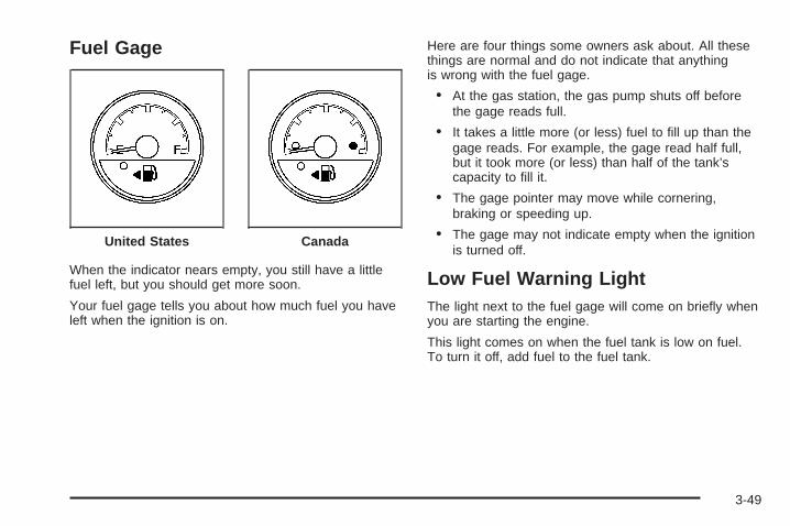
Fuel Gage
When the indicator nears empty, you still have a littlefuel left, but you should get more soon.
Your fuel gage tells you about how much fuel you haveleft when the ignition is on.
Here are four things some owners ask about. All thesethings are normal and do not indicate that anythingis wrong with the fuel gage.
• At the gas station, the gas pump shuts off beforethe gage reads full.
• It takes a little more (or less) fuel to fill up than thegage reads. For example, the gage read half full,but it took more (or less) than half of the tank’scapacity to fill it.
• The gage pointer may move while cornering,braking or speeding up.
• The gage may not indicate empty when the ignitionis turned off.
Low Fuel Warning LightThe light next to the fuel gage will come on briefly whenyou are starting the engine.
This light comes on when the fuel tank is low on fuel.To turn it off, add fuel to the fuel tank.
United States Canada
3-49

Driver Information Center (DIC)Your vehicle has a Driver Information Center (DIC).
All messages appear in the DIC display located in theinstrument panel cluster, below the tachometer. The DICbuttons are located on the center of the instrumentpanel, below the center outlets.
The DIC comes on when the ignition is on. After a shortdelay, the DIC displays WELCOME DRIVER (1 or 2)if a personalized key 1 or 2 is used, and then theinformation that was last displayed before the enginewas turned off. The driver number also correspondsto the numbers, 1 or 2, on the back of the remotekeyless entry transmitters.
The DIC displays the odometer, trip odometers, fueleconomy, trip computer, vehicle system information, andcompass display, if equipped. It also displays warningmessages if a system problem is detected. In addition,the DIC displays phone numbers that are called using theOnStar® system, if equipped. See OnStar® System onpage 2-47.
On some vehicles, the outside air temperatureautomatically appears in the bottom right cornerof the DIC display when viewing all of the informationscreens, except for the oil life screens. If the outside airtemperature is at or below 37°F (3°C), the temperaturereading will toggle between displaying the outsidetemperature and the word ICE for two minutes. If there isa problem with the system that controls the temperaturedisplay, the letters OC (open circuit) or SC (short circuit)will appear on the display. If this occurs, have the vehicleserviced by your dealer/retailer.
The DIC also allows some features to be customizedor personalized, if equipped. See DIC VehiclePersonalization (Uplevel Only) on page 3-76for more information.
DIC Operation and DisplaysThe DIC has different modes which can be accessed bypressing the DIC buttons located on the center of theinstrument panel. The buttons are the information,set/reset, and menu buttons.
The button functions are detailed in the following pages.
3-50

DIC Buttons
Q4R (Information): Press this button to display theodometer, trip distance, time elapsed, average speed,fuel economy, battery voltage, oil life, tire pressurereadings, and to turn off the DIC.
r (Set/Reset): Press this button to set or resetcertain functions and to turn off or acknowledgemessages on the DIC.
q (Menu): Press this button to display the units,language, personalization, if equipped, compass zoneand compass calibration, if equipped. See DIC VehiclePersonalization (Uplevel Only) on page 3-76 andDIC Compass (Uplevel Only) on page 3-56 for moreinformation.
Information Button Items
Q4R (Information): Press this button to scrollthrough the following items:
OdometerPress the information button until the odometer displays.This mode shows the distance the vehicle has beendriven in either miles or kilometers.
Trip A and Trip BPress the information button until A or B displays.This mode shows the current distance traveled ineither miles or kilometers since the last reset for eachtrip odometer. Both trip odometers can be used atthe same time.
The display will show the odometer on the top line andthe trip odometer information, either A or B, on thebottom line.
Each trip odometer can be reset to zero separatelyby pressing the set/reset button while the desired tripodometer is displayed.
3-51

There is also a retroactive trip odometer function thatperforms the following for each trip odometer:
• If the vehicle’s speed has exceeded 3 mph (5 km/h)during the current ignition cycle, this function willset the trip odometer to the distance drivenduring the current ignition cycle.
• If the vehicle’s speed has not exceeded 3 mph(5 km/h), this function will set the trip odometerto the distance driven during the previous ignitioncycle plus the distance driven during the currentignition cycle.
Press and hold the set/reset button for three seconds,then release the button. The retroactive trip odometervalue will be set into the currently displayed tripodometer.
Time ElapsedPress the information button until TIME ELAPSED :00displays. This mode is like a stopwatch, in that you canclock the time it takes to get from one point to another.Each of the fields for the hours, minutes, and secondsare two numeric digits.
Once TIME ELAPSED :00 is displayed, press theset/reset button to start the timing feature. Press theset/reset button again to stop it. If you will be startingand stopping your vehicle, during a trip for instance, theTIME ELAPSED feature will automatically start timingwhere it left off when you last stopped. To reset it, pressand hold the set/reset button for about 1.5 seconds.The display will return to zero.
Average SpeedPress the information button until AVERAGE SPEEDdisplays. This mode shows the average speed of thevehicle in miles per hour (mph) or kilometers per hour(km/h). This average is calculated based on the variousvehicle speed recorded since the last reset of this value.To reset the value, press the information button to displayAVERAGE SPEED, then press and hold the set/resetbutton. The display will return to zero.
3-52

Fuel RangePress the information button until FUEL RANGEdisplays. This mode shows the approximate numberof remaining miles or kilometers the vehicle canbe driven without refueling.
Fuel range is based on several factors, includingdistance travelled, fuel used, fuel capacity, etc.This estimate will change if driving conditions change.For example, if driving in traffic and making frequentstops, this mode may read one number, but if the vehicleis driven on a freeway, the number may change eventhough the same amount of fuel is in the fuel tank.This is because different driving conditions producedifferent fuel economies. Generally, freeway drivingproduces better fuel economy than city driving.Fuel range cannot be reset.
If your vehicle is low on fuel, FUEL RANGE LOWwill display followed by the LOW FUEL message.See “LOW FUEL” under DIC Warnings and Messageson page 3-58 for more information.
Average Fuel EconomyPress the information button until AVG ECONOMYdisplays. This mode shows the approximate averagemiles per gallon (mpg) or liters per 100 kilometers(L/100 km). This number is calculated based on thenumber of mpg (L/100 km) recorded since the last timethis menu item was reset. To reset AVG ECONOMY,press and hold the set/reset button. The displaywill return to zero.
BatteryPress the information button until BATTERY displays.This mode shows the current battery voltage.
Your vehicle’s charging system regulates voltage basedon the state of the battery. The battery voltage mayfluctuate when viewing this information on the DIC.This is normal.
If there is a problem with the battery charging system,a DIC message will display. See DIC Warnings andMessages on page 3-58 and Electric PowerManagement on page 3-20 for more information.
3-53

Oil LifePress the information button until OIL LIFE displays.This mode shows an estimate of the oil’s remaininguseful life. If you see OIL LIFE 99% on the display, thatmeans 99% of the current oil life remains. The engineoil life system will alert you to change the oil on aschedule consistent with your driving conditions.
When the remaining oil life is low, the CHANGE OILSOON message will appear on the display. You shouldchange the oil as soon as possible. See Engine Oil onpage 5-13. In addition to the engine oil life systemmonitoring the oil life, additional maintenance isrecommended in the Maintenance Schedule in thismanual. See Scheduled Maintenance on page 6-4for more information.
Remember, you must reset the OIL LIFE yourselfafter each oil change. It will not reset itself. Also,be careful not to reset the OIL LIFE accidentally at anytime other than when the oil has just been changed.It cannot be reset accurately until the next oil change.To reset the engine oil life system, see Engine OilLife System on page 5-16. The display will show 100%when the system is reset.
Tire PressurePress the information button until FRONT TIREPRESSURE displays. This mode shows the pressurefor the front tires. To view the pressure for the rear tires,press the information button again until REAR TIREPRESSURE displays. The tire pressure will be shown ineither pounds per square inch (psi) or kilopascals (kPa).
If a low tire pressure condition is detected by the systemwhile driving, a message advising you to check thepressure in a specific tire will appear in the display.The tire pressure light will also flash and then remainon during the same ignition cycle. See Inflation - TirePressure on page 5-54 and DIC Warnings and Messageson page 3-58 for more information.
If the tire pressure display shows dashes or blanksinstead of a value, there may be a problem with yourvehicle. If this consistently occurs, see your dealerfor service.
3-54

Menu Button Items
q (Menu): Press this button to scroll through thefollowing items:
UnitsPress the menu button until UNITS displays. This modeallows you to select between English or Metric unitsof measurement. Once in this mode, press the set/resetbutton to select between ENGLISH or METRIC.
LanguagePress the menu button until the language screendisplays. This mode allows you to select the language inwhich the DIC messages will appear. Once in this mode,press the set/reset button to select among the followingchoices:
• English
• Francais (French)
• Espanol (Spanish)
Personalization (Uplevel Only)Press the menu button until PERSONAL PROGRAMdisplays. Your vehicle may have personalizationcapabilities that allow you to program certain featuresto a preferred setting for up to two drivers.
Your vehicle may also have customization capabilitiesthat allow you to program certain features to onepreferred setting. Customization features can only beprogrammed to one setting on the vehicle and cannot beprogrammed to a preferred setting for up to two drivers.See DIC Vehicle Personalization (Uplevel Only) onpage 3-76 for additional information on personalprogramming.
Compass Zone (Uplevel Only)To change the compass zone through the DIC,see DIC Compass (Uplevel Only) on page 3-56.
Compass Calibration (Uplevel Only)The compass can be manually calibrated. To calibratethe compass through the DIC, see DIC Compass(Uplevel Only) on page 3-56.
3-55

DIC Compass (Uplevel Only)Your vehicle may have a compass in the DriverInformation Center (DIC).
Compass ZoneThe zone is set to zone eight upon leaving the factory.Your dealer/retailer will set the correct zone for yourlocation.
Under certain circumstances, such as during a longdistance cross-country trip or moving to a new stateor province, it will be necessary to compensate forcompass variance by resetting the zone through theDIC if the zone is not set correctly.
Compass variance is the difference between the earth’smagnetic north and true geographic north. If the compassis not set to the zone where you live, the compass maygive false readings. The compass must be set to thevariance zone in which the vehicle is traveling.
To adjust for compass variance, use the followingprocedure:
Compass Variance (Zone) Procedure1. Do not set the compass zone when the vehicle is
moving. Only set it when the vehicle is in PARK (P).Press the menu button until COMPASS ZONEdisplays.
2. Find the vehicle’s current location and variancezone number on the map.Zones 1 through 15 are available.
3. Press the set/reset button to scroll through andselect the appropriate variance zone.The direction the vehicle is moving will be shown inthe top right corner of the DIC display.
4. If calibration is necessary, calibrate the compass.See “Compass Calibration Procedure” following.
3-56

Compass CalibrationThe compass can be manually calibrated. Only calibratethe compass in a magnetically clean and safe location,such as an open parking lot, where driving the vehiclein circles is not a danger. It is suggested to calibrateaway from tall buildings, utility wires, manhole covers,or other industrial structures, if possible.
If CAL should ever appear in the DIC display, thecompass should be calibrated.
If the DIC display does not show a heading, for example,N for North, or the heading does not change aftermaking turns, there may be a strong magnetic fieldinterfering with the compass. Such interference maybe caused by a magnetic CB or cell phone antennamount, a magnetic emergency light, magnetic notepad holder, or any other magnetic item. Turn offthe vehicle, move the magnetic item, then turn onthe vehicle and calibrate the compass.
To calibrate the compass, use the following procedure:
Compass Calibration Procedure1. Before calibrating the compass, make sure the
compass zone is set to the variance zone inwhich the vehicle is located. See “CompassVariance (Zone) Procedure” earlier in this section.Do not operate any switches such as window,sunroof, climate controls, seats, etc. duringthe calibration procedure.
2. Press the menu button until COMPASSCALIBRATION displays.
3. Press the set/reset button to start the compasscalibration.
4. The DIC will display CALIBRATION BEGUN DRIVEUNTIL DONE. Drive the vehicle in tight circles atless than 5 mph (8 km/h) to complete the calibration.The DIC will display CALIBRATION FINISHEDfor a few seconds when the calibration is complete.
3-57

DIC Warnings and MessagesMessages are displayed on the DIC to notify the driverthat the status of the vehicle has changed and thatsome action may be needed by the driver to correctthe condition. Multiple messages may appear one afteranother.
Some messages may not require immediate action, butyou can press any of the DIC buttons to acknowledgethat you received the message and clear it from theDIC display.
Some messages cannot be cleared from the DIC displaybecause they are more urgent. These messages requireaction before they can be cleared.
If there are any active warning messages when thevehicle is turned off, two chimes sound and the DIC goesinto a reminder mode. The reminder mode displays anyactive message. If there are multiple messages, the DICdisplays each message for five seconds. After eachactive message is displayed once, the reminder modeturns off.
You should take any messages that appear on thedisplay seriously and remember that clearing themessages will only make the messages disappear,not correct the problem.
The following are the possible messages that can bedisplayed and some information about them.
A/C OFF FOR ENGINE PROTECTIONThis message displays when the engine coolantbecomes hotter than the normal operating temperature.See Engine Coolant Temperature Gage on page 3-43.To avoid added strain on a hot engine, the airconditioning compressor is automatically turned off.When the coolant temperature returns to normal, the airconditioning compressor turns back on. You can continueto drive your vehicle.
This message comes on while the ignition is in ON/RUN.Press any of the DIC buttons to acknowledge thiswarning message and to clear it from the screen.
This message continues to display for two seconds if ithas not been acknowledged when the engine is turnedoff. It also re-displays for two seconds if the message hasbeen acknowledged, but the condition still exists whenthe engine is turned off.
If the condition still exists, the message re-appearswhen the engine is turned on. If this message continuesto appear, have the system repaired by your dealer/retailer as soon as possible to avoid damage to theengine.
3-58

BATTERY SAVER ACTIVEThis message displays when the system detects thatthe battery voltage is dropping beyond a reasonablelevel. The battery saver system starts reducing certainfeatures of the vehicle that you may be able to notice.At the point that the features are disabled, this messageis displayed. It means that the vehicle is trying tosave the charge in the battery.
Turn off all unnecessary accessories to allow the batteryto recharge.
The normal battery voltage range is 11.5 to 15.5 volts.You can monitor the battery voltage by pressing theinformation button until BATTERY displays.
CHANGE OIL SOONThis message displays when service is required for thevehicle. See your dealer/retailer. See Engine Oil onpage 5-13 and Scheduled Maintenance on page 6-4for more information.
The CHANGE OIL SOON message is reset byacknowledging the message. The OIL LIFE screenunder the gages menu on the DIC must also be reset.See “Oil Life” under DIC Operation and Displays onpage 3-50 and Engine Oil Life System on page 5-16.
This message displays while the ignition is in ON/RUN.Press any of the DIC buttons to acknowledge thismessage and to clear it from the screen.
This message continues to display for two seconds if ithas not been acknowledged when the engine is turnedoff. It also re-displays for two seconds if the message hasbeen acknowledged, but the condition still exists whenthe engine is turned off.
If the condition still exists, the message re-appearswhen the engine is turned on.
CHARGING SYSTEM FAILUREThis message displays when there is a problem with thegenerator and battery charging systems. Driving with thisproblem could drain the battery. Turn off all unnecessaryaccessories. Stop and turn off the vehicle as soon as it issafe to do so. Have the electrical system checked by yourdealer/retailer immediately.
This message displays and a chime sounds while theignition is in ON/RUN. Press any of the DIC buttonsto acknowledge this message and to clear it from thescreen.
This message continues to display for two seconds if ithas not been acknowledged when the engine is turnedoff. It also re-displays for two seconds if the message hasbeen acknowledged, but the condition still exists whenthe engine is turned off.
If the condition still exists, the message re-appearswhen the engine is turned on.
3-59

CHECK GAS CAPThis message displays if the fuel cap is not on, or is notfully tightened. Check the fuel cap to ensure that it ison properly. See Filling the Tank on page 5-8 for moreinformation.
This message displays and a chime sounds while theignition is in ON/RUN. Press any of the DIC buttonsto acknowledge this message and to clear it from thescreen.
This message continues to display for two seconds if ithas not been acknowledged when the engine is turnedoff. It also re-displays for two seconds if the message hasbeen acknowledged, but the condition still exists whenthe engine is turned off.
If the condition still exists, the message re-appearswhen the engine is turned on.
CHECK TIRE PRESSUREThis message displays when the pressure in one or moreof the vehicle’s tires needs to be checked. This messagealso displays LEFT FRONT, RIGHT FRONT, LEFTREAR, or RIGHT REAR to indicate which tire needs to be
checked. You can receive more than one tire pressuremessage at a time. To read the other messages that mayhave been sent at the same time, press the set/resetbutton. If a tire pressure message appears on the DIC,stop as soon as you can. Have the tire pressureschecked and set to those shown on the Tire LoadingInformation label. See Tires on page 5-48, Loading YourVehicle on page 4-21, and Inflation - Tire Pressure onpage 5-54. The DIC also shows the tire pressure values.See DIC Operation and Displays on page 3-50. If the tirepressure is low, the low tire pressure warning light comeson. See Tire Pressure Light on page 3-43.
This message displays while the ignition is in ON/RUN.Press any of the DIC buttons to acknowledge thismessage and to clear it from the screen.
This message continues to display for two seconds if ithas not been acknowledged when the engine is turnedoff. It also re-displays for two seconds if the message hasbeen acknowledged, but the condition still exists whenthe engine is turned off.
If the condition still exists, the message re-appearswhen the engine is turned on.
3-60

DELAYED LOCKINGThis message displays to inform the driver that eventhough a door lock switch or the lock button on theRemote Keyless Entry (RKE) transmitter has beenpressed, that actual locking of the doors is being delayedbecause the delayed locking feature has been activatedin the DIC. See “DELAYED LOCKING” under DIC VehiclePersonalization (Uplevel Only) on page 3-76 for moreinformation.
This message appears and a chime sounds when theignition is off.
This message cannot be acknowledged.
DRIVER’S DOOR AJARThis message displays when the driver door is notclosed properly. Make sure that the door is closedcompletely.
This message displays while the ignition is in ON/RUN.A chime sounds when the ignition is shifted out ofPARK (P). Press any of the DIC buttons to acknowledgethis message and to clear it from the screen.
This message continues to display for two secondsif it has not been acknowledged when the engineis turned off. It also re-displays for two seconds if themessage has been acknowledged, but the conditionstill exists when the engine is turned off.
If the condition still exists, the message re-appearswhen the engine is turned on.
DRIVER’S REAR DOOR AJARThis message displays when the driver side rear door isnot closed properly. Make sure that the door is closedcompletely.
This message displays while the ignition is in ON/RUN.A chime sounds when the ignition is shifted out ofPARK (P). Press any of the DIC buttons to acknowledgethis message and to clear it from the screen.
This message continues to display for two secondsif it has not been acknowledged when the engineis turned off. It also re-displays for two seconds if themessage has been acknowledged, but the conditionstill exists when the engine is turned off.
If the condition still exists, the message re-appearswhen the engine is turned on.
3-61

ENGINE COOLANT HOT
Notice: If you drive your vehicle while the engineis overheating, severe engine damage may occur.If an overheat warning appears on the instrumentpanel cluster and/or DIC, stop the vehicle as soon aspossible. Do not increase the engine speed abovenormal idling speed. See Engine Overheatingon page 5-24 for more information.
This message displays when the engine coolanttemperature is too hot. The engine coolant temperaturewarning light also appears on the instrument panelcluster. See Engine Coolant Temperature Gageon page 3-43 for more information.
To avoid added strain on the engine, turn off the airconditioner if it is on. When the coolant temperaturereturns to normal, the air conditioner can be turnedback on.
This message displays only when the ignition is inON/RUN. A chime sounds continuously when thismessage is displayed. Press any of the DIC buttonsto acknowledge this message and to clear it fromthe screen.
This message continues to display for two secondsif it has not been acknowledged when the engineis turned off. It also re-displays for two seconds if themessage has been acknowledged, but the conditionstill exists when the engine is turned off.
If the condition still exists, the message re-appearswhen the engine is turned on.
HEADLAMPS SUGGESTEDThis message displays when the amount of available lightoutside of the vehicle is low, or the windshield wipershave been on for about 30 seconds, and the exteriorlamps control is off or in the park lamps position. Thismessage informs the driver that turning on the exteriorlamps is recommended. See Exterior Lamps onpage 3-14 for more information.
This message displays while the ignition is in ON/RUN.Press any of the DIC buttons to acknowledge thismessage and to clear it from the screen.
This message continues to display for two secondsif it has not been acknowledged when the engineis turned off. It also re-displays for two seconds if themessage has been acknowledged, but the conditionstill exists when the engine is turned off.
If the condition still exists, the message re-appearswhen the engine is turned on.
3-62

HOOD AJARIf your vehicle has the remote start feature, thismessage displays when the hood is not closedproperly. Make sure that the hood is closed completely.See Hood Release on page 5-11.
This message displays while the ignition is in ON/RUN.Press any of the DIC buttons to acknowledge thismessage and to clear it from the screen.
This message continues to display for two secondsif it has not been acknowledged when the engineis turned off. It also re-displays for two seconds if themessage has been acknowledged, but the conditionstill exists when the engine is turned off.
If the condition still exists, the message re-appearswhen the engine is turned on.
KEY FOB BATTERY LOWThis message displays when the battery in the RemoteKeyless Entry (RKE) transmitter needs to be replaced.To replace the battery, see “Battery Replacement” underRemote Keyless Entry (RKE) System Operation onpage 2-5.
This message displays while the ignition is in ON/RUN.Press any of the DIC buttons to acknowledge thismessage and to clear it from the screen.
This message continues to display for two secondsif it has not been acknowledged when the engineis turned off. It also re-displays for two seconds if themessage has been acknowledged, but the conditionstill exists when the engine is turned off.
If the condition still exists, the message re-appearswhen the engine is turned on.
KEY IN IGNITIONThis message displays and a chime soundscontinuously when the driver’s door is open andthe key is in ACC/ACCESSORY or LOCK/OFF.
This message cannot be acknowledged.
This message disappears and the chiming stops whenthe key is removed from the ignition.
3-63

LEFT FRONT TURN LAMP OUTThis message displays when the left front turn signalbulb needs to be replaced. See Headlamps andSidemarker Lamps on page 5-42.
This message displays while the ignition is in ON/RUN.Press any of the DIC buttons to acknowledge thismessage and to clear it from the screen.
This message continues to display for two secondsif it has not been acknowledged when the engineis turned off. It also re-displays for two seconds if themessage has been acknowledged, but the conditionstill exists when the engine is turned off.
If the condition still exists, the message re-appearswhen the engine is turned on.
LEFT REAR TURN LAMP OUTThis message displays when the left rear turn signalbulb needs to be replaced. See Taillamps, Turn Signal,Stoplamps and Back-up Lamps on page 5-44.
This message displays while the ignition is in ON/RUN.Press any of the DIC buttons to acknowledge thismessage and to clear it from the screen.
This message continues to display for two secondsif it has not been acknowledged when the engineis turned off. It also re-displays for two seconds if themessage has been acknowledged, but the conditionstill exists when the engine is turned off.
If the condition still exists, the message re-appearswhen the engine is turned on.
LIFT GATE AJARThis message displays when the liftgate is not closedcompletely. Make sure that the liftgate is closedcompletely. See Liftgate on page 2-22.
This message displays while the ignition is in ON/RUN.A chime sounds when the ignition is shifted out ofPARK (P). Press any of the DIC buttons to acknowledgethis message and to clear it from the screen.
This message continues to display for two secondsif it has not been acknowledged when the engineis turned off. It also re-displays for two seconds if themessage has been acknowledged, but the conditionstill exists when the engine is turned off.
If the condition still exists, the message re-appearswhen the engine is turned on.
3-64

LOW BRAKE FLUIDThis message displays when the brake fluid level is low.Have the brake system serviced by your dealer/retaileras soon as possible. See Brakes on page 5-33 forproper fluid level.
The brake system warning light also appears on theinstrument panel cluster when this message appears onthe DIC. See Brake System Warning Light on page 3-41.
This message displays and a chime sounds only whilethe ignition is in ON/RUN. Press any of the DIC buttonsto acknowledge this message and to clear it from thescreen.
This message continues to display for two secondsif it has not been acknowledged when the engineis turned off. It also re-displays for two seconds if themessage has been acknowledged, but the conditionstill exists when the engine is turned off.
If the condition still exists, the message re-appearswhen the engine is turned on.
LOW FUELThis message displays when your vehicle is low on fuel.Refill the fuel tank as soon as possible. See Fuel Gageon page 3-49 and Filling the Tank on page 5-8 for moreinformation.
The message displays and a chime sounds while theignition is in ON/RUN. Press any of the DIC buttons toacknowledge this message and to clear it from thescreen.
If the condition still exists, the message re-appearswhen the engine is turned on.
LOW OIL PRESSURE
Notice: If the LOW OIL PRESSURE warningmessage appears on the DIC display, stop thevehicle immediately. Do not drive the vehicle untilthe cause of the low oil pressure is corrected.Severe engine damage can result from driving avehicle with low oil pressure. See Engine Oilon page 5-13 for more information.
This message displays when the vehicle’s engine oilpressure is low. The oil pressure light also appears onthe instrument panel cluster. See Oil Pressure Lighton page 3-47.
Stop the vehicle immediately, as engine damage canresult from driving a vehicle with low oil pressure. Havethe vehicle serviced by your dealer/retailer as soonas possible when this message is displayed.
This message displays only when the ignition is inON/RUN. A chime sounds continuously when thismessage is displayed.
3-65

This message cannot be acknowledged and clearedfrom the screen. This message re-displays for afew seconds if the condition still exists when theengine is turned off.
If the condition still exists, the message re-appearswhen the engine is turned on.
PARKING BRAKE ONThis message displays to alert the driver when thevehicle’s parking brake is on, the ignition is in ON/RUN,and the vehicle speed is greater than 5 mph (8 km/h).Release the parking brake before driving. See ParkingBrake on page 2-38 for more information.
The brake system warning light also appears on theinstrument panel cluster when this message appears onthe DIC. See Brake System Warning Light on page 3-41.
A chime sounds continuously while this message isdisplayed if driving above 5 mph (8 km/h). Press anyof the DIC buttons to acknowledge this message andto clear it from the screen.
This message continues to display for two secondsif it has not been acknowledged when the engineis turned off. It also re-displays for two seconds if themessage has been acknowledged, but the conditionstill exists when the engine is turned off.
If the condition still exists, the message re-appearswhen the engine is turned on.
PARK LAMPS ONThis message displays to alert the driver when theheadlamps or parking lamps are on while the ignitionis off and the driver’s door is opened. See ExteriorLamps on page 3-14 for more information. A chimesounds continuously while this message is displayed.
Press any of the DIC buttons to acknowledge thismessage and to clear it from the screen.
PASSENGER’S DOOR AJARThis message displays when the front passenger dooris not closed properly. Make sure that the door is closedcompletely.
This message displays while the ignition is in ON/RUN.A chime sounds when the ignition is shifted out ofPARK (P). Press any of the DIC buttons to acknowledgethis message and to clear it from the screen.
This message continues to display for two secondsif it has not been acknowledged when the engineis turned off. It also re-displays for two seconds if themessage has been acknowledged, but the conditionstill exists when the engine is turned off.
If the condition still exists, the message re-appearswhen the engine is turned on.
3-66

PASSENGER’S REAR DOOR AJARThis message displays when the passenger side reardoor is not closed properly. Make sure that the dooris closed completely.
This message displays while the ignition is in ON/RUN.A chime sounds when the ignition is shifted out ofPARK (P). Press any of the DIC buttons to acknowledgethis message and to clear it from the screen.
This message continues to display for two secondsif it has not been acknowledged when the engineis turned off. It also re-displays for two seconds if themessage has been acknowledged, but the conditionstill exists when the engine is turned off.
If the condition still exists, the message re-appearswhen the engine is turned on.
PASSENGER SEATBELT IS NOTFASTENEDThis message reminds you to buckle the passenger’ssafety belt.
This message displays and a chime sounds when theignition is on, the driver’s safety belt is buckled, thepassenger’s safety belt is unbuckled with the passengerairbag enabled, and the vehicle is in motion. You shouldhave the passenger buckle their safety belt.
The reminder will be repeated if the ignition is on, thevehicle is in motion, the driver is unbuckled and thepassenger is still unbuckled and the passenger airbagis enabled. If the passenger’s safety belt is alreadybuckled, this message and chime will not come on.
REDUCED ENGINE POWERThis message displays when the vehicle’s engine poweris reduced. This happens when driving conditions,such as climbing a steep hill, make the transmissionoverwork in a gear that may cause damage to thevehicle’s engine or transmission. Reduced enginepower can affect the vehicle’s ability to accelerate.
This message displays and a chime sounds onlywhen the ignition is in ON/RUN. Press any of the DICbuttons to acknowledge this message and to clearit from the screen.
This message continues to display for two secondsif it has not been acknowledged when the engineis turned off. It also re-displays for two seconds if themessage has been acknowledged, but the conditionstill exists when the engine is turned off.
If the condition still exists, the message re-appearswhen the engine is turned on.
3-67

REDUCED POWER STOP WHEN SAFEThis message displays when your vehicle is in anoverheated engine operating mode. This operating modeallows your vehicle to be driven to a safe place in anemergency. In this mode, you will notice a significantloss in power and engine performance. See OverheatedEngine Protection Operating Mode on page 5-25 formore information. Anytime this message is on, thevehicle should be taken to your dealer/retailer forservice as soon as possible.
This message displays and a chime sounds onlywhen the ignition is in ON/RUN. Press any of theDIC buttons to acknowledge this message and toclear it from the screen.
This message continues to display for two secondsif it has not been acknowledged when the engineis turned off. It also re-displays for two seconds if themessage has been acknowledged, but the conditionstill exists when the engine is turned off.
If the condition still exists, the message re-appearswhen the engine is turned on.
REMOTE START DISABLEDIf your vehicle has the remote start feature, this messagedisplays if a remote start attempt is unsuccessful. Thismay be caused if any of the following conditions are truewhen a remote start attempt is made:
• The remote start system is disabled through the DIC.
• The key is in the ignition.
• The hood or the doors are not closed.
• There is an emission control system malfunction.
• The engine coolant temperature is too high.
• The oil pressure is low.
• The hazard warning flashers are turned on.
• The maximum number of remote starts or remotestart attempts between ignition cycles has beenreached.
• The content theft-deterrent alarm is on whileattempting to remote start the vehicle.
See “REMOTE START” under DIC VehiclePersonalization (Uplevel Only) on page 3-76 and“Remote Vehicle Start” under Remote Keyless Entry(RKE) System Operation on page 2-5 for moreinformation.
3-68

REMOTE START ONIf your vehicle has the remote start feature, thismessage displays when a remote start is initiated. See“Remote Vehicle Start” under Remote Keyless Entry(RKE) System Operation on page 2-5 for moreinformation.
RIGHT FRONT TURN LAMP OUTThis message displays when the right front turn signalbulb needs to be replaced. See Headlamps andSidemarker Lamps on page 5-42.
This message displays while the ignition is in ON/RUN.Press any of the DIC buttons to acknowledge thismessage and to clear it from the screen.
This message continues to display for two secondsif it has not been acknowledged when the engineis turned off. It also re-displays for two seconds if themessage has been acknowledged, but the conditionstill exists when the engine is turned off.
If the condition still exists, the message re-appearswhen the engine is turned on.
RIGHT REAR TURN LAMP OUTThis message displays when the right rear turn signalbulb needs to be replaced. See Taillamps, Turn Signal,Stoplamps and Back-up Lamps on page 5-44.
This message displays while the ignition is in ON/RUN.Press any of the DIC buttons to acknowledge thismessage and to clear it from the screen.
This message continues to display for two secondsif it has not been acknowledged when the engineis turned off. It also re-displays for two seconds if themessage has been acknowledged, but the conditionstill exists when the engine is turned off.
If the condition still exists, the message re-appearswhen the engine is turned on.
3-69

SERVICE ABS SYSTEMThis message displays when the vehicle’s AntilockBrake System (ABS) is not functioning properly.Have the ABS serviced by your dealer/retailer assoon as possible.
The ABS warning light also appears on the instrumentpanel cluster when this message appears on theDIC. See Antilock Brake System Warning Lighton page 3-42.
This message only displays while the ignition is inON/RUN. Press any of the DIC buttons to acknowledgethis message and to clear it from the screen.
This message continues to display for two secondsif it has not been acknowledged when the engineis turned off. It also re-displays for two seconds if themessage has been acknowledged, but the conditionstill exists when the engine is turned off.
If the condition still exists, the message re-appearswhen the engine is turned on.
SERVICE AIR BAGThis message displays along with the airbag readinesslight if there is a problem with the airbag system. Haveyour dealer/retailer inspect the system for problems. SeeAirbag Readiness Light on page 3-37 and Airbag Systemon page 1-77 for more information.
This message only displays while the ignition is inON/RUN. Press any of the DIC buttons to acknowledgethis message and to clear it from the screen.
This message continues to display for two secondsif it has not been acknowledged when the engineis turned off. It also re-displays for two seconds if themessage has been acknowledged, but the conditionstill exists when the engine is turned off.
If the condition still exists, the message re-appearswhen the engine is turned on.
3-70

SERVICE BRAKE SYSTEMThis message displays when a problem with thebrake system has been detected. Have your vehicleserviced by your dealer/retailer as soon as possible.
The brake system warning light also appears onthe instrument panel cluster when this messageappears on the DIC. See Brake System WarningLight on page 3-41.
This message only displays while the ignition is inON/RUN. Press any of the DIC buttons to acknowledgethis message and to clear it from the screen.
This message continues to display for two secondsif it has not been acknowledged when the engineis turned off. It also re-displays for two seconds if themessage has been acknowledged, but the conditionstill exists when the engine is turned off.
If the condition still exists, the message re-appearswhen the engine is turned on.
SERVICE PARK LAMPSThis message displays when there is a problem withthe park lamps. Check to see if the park lamp fuseis blown and replace the fuse if necessary. See Fusesand Circuit Breakers on page 5-100 and InstrumentPanel Fuse Block on page 5-100 for more information.If changing the fuse does not correct the problem,see your dealer/retailer.
This message only displays while the ignition is inON/RUN. Press any of the DIC buttons to acknowledgethis message and to clear it from the screen.
This message continues to display for two secondsif it has not been acknowledged when the engineis turned off. It also re-displays for two seconds if themessage has been acknowledged, but the conditionstill exists when the engine is turned off.
If the condition still exists, the message re-appearswhen the engine is turned on.
3-71

SERVICE STABILITY SYSTEMIf your vehicle has StabiliTrak®, this message displays ifthere has been a problem detected with StabiliTrak®.See StabiliTrak® System on page 4-7.
If this message turns on while you are driving, pull offthe road as soon as possible and stop carefully. Tryresetting the system by turning the ignition off and thenback on. If this message still stays on or turns back onagain while you are driving, your vehicle needs service.Have the StabiliTrak® System inspected by your dealer/retailer as soon as possible.
This message displays only while the ignition is inON/RUN. Press any of the DIC buttons to acknowledgethis message and to clear it from the screen.
This message continues to display for two secondsif it has not been acknowledged when the engineis turned off. It also re-displays for two seconds if themessage has been acknowledged, but the conditionstill exists when the engine is turned off.
If the condition still exists, the message re-appearswhen the engine is turned on.
SERVICE TIRE MONITOR SYSTEMThis message displays if a part on the Tire PressureMonitor System (TPMS) is not working properly. The tirepressure light also flashes and then remains on duringthe same ignition cycle. See Tire Pressure Light onpage 3-43. Several conditions may cause this messageto appear. See Tire Pressure Monitor Operation onpage 5-58 for more information. If the warning comes onand stays on, there may be a problem with the TPMS.See your dealer/retailer.
This message displays while the ignition is in ON/RUN.Press any of the DIC buttons to acknowledge thismessage and to clear it from the screen.
This message continues to display for two secondsif it has not been acknowledged when the engineis turned off. It also re-displays for two seconds if themessage has been acknowledged, but the conditionstill exists when the engine is turned off.
If the condition still exists, the message re-appearswhen the engine is turned on.
3-72

SERVICE TRACTION SYSTEMIf your vehicle has the Traction Control System (TCS),this message displays when the system is not functioningproperly. A warning light also appears on the instrumentpanel cluster. See Traction Control System (TCS)Warning Light on page 3-42. See Traction ControlSystem (TCS) on page 4-6 for more information.Have the TCS serviced by your dealer/retailer assoon as possible.
This message displays only while the ignition is inON/RUN. Press any of the DIC buttons to acknowledgethis message and to clear it from the screen.
This message continues to display for two secondsif it has not been acknowledged when the engineis turned off. It also re-displays for two seconds if themessage has been acknowledged, but the conditionstill exists when the engine is turned off.
If the condition still exists, the message re-appearswhen the engine is turned on.
SERVICE VEHICLE SOONThis message displays when a non-emissions relatedmalfunction occurs. Have the vehicle serviced byyour dealer/retailer as soon as possible.
This message displays only while the ignition is inON/RUN. Press any of the DIC buttons to acknowledgethis message and to clear it from the screen.
This message continues to display for two secondsif it has not been acknowledged when the engineis turned off. It also re-displays for two seconds if themessage has been acknowledged, but the conditionstill exists when the engine is turned off.
If the condition still exists, the message re-appearswhen the engine is turned on.
STABILITY CONTROL ACTIVEIf your vehicle has StabiliTrak®, this message displayswhen StabiliTrak® is actively assisting you with directionalcontrol of the vehicle. Slippery road conditions may existwhen this message is displayed, so adjust your drivingaccordingly. See StabiliTrak® System on page 4-7.
This message displays only while the ignition is inON/RUN. This message stays on until road conditionschange and StabiliTrak® is not active.
This message cannot be acknowledged and clearedfrom the screen.
3-73

STABILITY CONTROL OFFIf your vehicle has StabiliTrak®, this message displaysany time the system turns off. When this message hasbeen displayed, StabiliTrak® is no longer available toassist you with directional control of the vehicle. Adjustyour driving accordingly. See StabiliTrak® System onpage 4-7.
This message displays only while the ignition is inON/RUN.
Any of the following conditions may cause theStabiliTrak® system to turn off:
• The battery is low.
• There is a StabiliTrak® system failure. See yourdealer/retailer for service.
STARTING DISABLEDThis message displays if the starting of the engine isdisabled due to the electronic throttle control systemor vehicle theft-deterrent system. Have your vehicleserviced by your dealer/retailer immediately.
This message only appears while the ignition is inON/RUN and will not disappear until the problem isresolved.
This message cannot be acknowledged.
TRACTION CONTROL ACTIVEIf your vehicle has the Traction Control System (TCS),this message displays when the system is on. Slipperyroad conditions may exist if this message is displayed,so adjust your driving accordingly. See Traction ControlSystem (TCS) on page 4-6 for more information.
This message only displays while the ignition is inON/RUN and will not disappear until driving conditionschange and the TCS is no longer active.
This message cannot be acknowledged or cleared fromthe screen.
TRACTION CONTROL OFFIf your vehicle has the Traction Control System (TCS),this message displays when the TCS turns off. SeeTraction Control System (TCS) on page 4-6 for moreinformation.
This message only displays while the ignition is inON/RUN and disappears after two seconds.
3-74

Any of the following conditions may cause the TCS toturn off:
• The TCS is turned off by pressing the tractioncontrol button located on the center of the instrumentpanel. See Traction Control System (TCS) onpage 4-6.
• The battery is low.
• There is a TCS failure. See your dealer/retailer forservice.
TRANSMISSION FLUID HOTThis message displays when the transmission fluid inyour vehicle is too hot. Stop the vehicle and allowit to idle until it cools down. If the warning messagecontinues to display, have the vehicle serviced by yourdealer/retailer as soon as possible.
This message displays and a chime sounds onlywhile the ignition is in ON/RUN. Press any of the DICbuttons to acknowledge this message and to clearit from the screen.
This message continues to display for two seconds if ithas not been acknowledged when the engine is turnedoff. It also re-displays for two seconds if the message hasbeen acknowledged, but the condition still exists whenthe engine is turned off.
If the condition still exists, the message re-appearswhen the engine is turned on.
TURN SIGNAL ONThis message displays as a reminder to turn off the turnsignal if you drive your vehicle for more than about0.75 mile (1.2 km) with a turn signal on. See TurnSignal/Multifunction Lever on page 3-7.
This message displays and a chime sounds only whenthe ignition is in ON/RUN. This message clears fromthe DIC if the turn signal is manually turned off, a turnis completed, or the message is acknowledged.
3-75

DIC Vehicle Personalization(Uplevel Only)Your vehicle may have customization capabilities thatallow you to program certain features to one preferredsetting. Customization features can only be programmedto one setting on the vehicle and cannot be programmedto a preferred setting for two different drivers.The customization features include the following:
• Exterior lighting delay
• Interior lighting delay
• Delayed locking
• Content theft
• Remote keyless entry feedback
• Remote start
• Rear park chime
Your vehicle may also have personalization capabilitiesthat allow you to program certain features to a preferredsetting for up to two drivers. The first personalized keycorresponds to driver 1 and the second personalizedkey corresponds to driver 2. The driver number alsocorresponds to the numbers, 1 or 2, on the back ofthe Remote Keyless Entry (RKE) transmitters.
The personalization features include the following:
• Radio station presets
• Auto door unlock preferences
• Remote keyless entry unlock preferences
All of the customization and personalization optionsmay not be available on your vehicle. Only the optionsavailable will be displayed on your DIC.
The default settings for the customization andpersonalization features were set when your vehicle leftthe factory, but may have been changed from theirdefault setting since then.
The customization preferences are automaticallyrecalled.
The driver’s personalization preferences are recalledby using the key programmed for driver 1 or 2. Thedriver number also corresponds to the numbers, 1 or 2,on the back of the RKE transmitters.
To change customization and personalizationpreferences, use the following procedure.
3-76

Entering the Personal Program Menu1. Turn the ignition on and place the vehicle in
PARK (P).To avoid excessive drain on the battery, it isrecommended that the headlamps are turned off.
2. Press the menu button until PERSONALPROGRAM displays.If the vehicle is not in PARK (P), PERSONALPROGRAM ONLY IN PARK will display.If the vehicle is not able to enter the personalprogram menu, PERSONAL PROGRAM NOTAVAILABLE will display.
3. Press the set/reset button to begin.
4. The DIC will then display an instruction screen.Press the menu button to display the modes thatare available to program.Press the set/reset button to change the setting ofeach mode.
Customization Menu ItemsThe following are customization features that allow youto program settings to the vehicle:
FACTORY DEFAULTSThis feature allows you to set all of the customizationand personalization features back to their factory defaultsettings.
Press the menu button until FACTORY DEFAULTSappears on the DIC display. Press the set/reset buttonto scroll through the following choices:
NO (default): The customization and personalizationfeatures will not be set to their factory default settings.
YES: The customization and personalization featureswill be set to their factory default settings.
If YES is selected, the keys will need to bepersonalized again to be recognized as key 1 or 2.See “PERSONALIZE KEY” later in this section formore information.
To select a setting and move on to the next feature,press the menu button while the desired setting isdisplayed on the DIC.
3-77

ALL KEYS RESETThis screen will only display if YES was selected on theFACTORY DEFAULTS screen.
Press the set/reset button to scroll through the followingchoices:
CANCEL (default): The features will not be set to theirfactory default settings and the DIC will return to theFACTORY DEFAULTS screen.
OK: The features will be set to their factory defaultsettings, the DIC will exit the personal program menu,and PERSONAL OPTIONS SAVED will display.
EXT (Exterior) LIGHT DELAYThis feature allows you to set the amount of time theexterior lamps remain on after the key is removed fromthe ignition or the vehicle is unlocked using the RKEtransmitter.
Press the menu button until EXT LIGHT DELAYappears on the DIC display. Press the set/reset buttonto scroll through the following choices:
OFF: The exterior lamps will not turn on.
15 seconds: The exterior lamps will stay on for15 seconds.
30 seconds (default): The exterior lamps will stay onfor 30 seconds.
60 seconds: The exterior lamps will stay on for60 seconds.
90 seconds: The exterior lamps will stay on for90 seconds.
To select a setting and move on to the next feature,press the menu button while the desired setting isdisplayed on the DIC.
INT (Interior) LIGHTS KEYS REMOVEDThis feature enables the interior lamps in the vehicle toturn on for about 25 seconds after the key is removedfrom the ignition.
Press the menu button until INT LIGHTS KEYSREMOVED appears on the DIC display. Press theset/reset button to scroll through the following choices:
OFF: Removing the key from the ignition will notcause the interior lamps to turn on.
ON (default): Removing the key from the ignition willcause the interior lamps to be turned on for about25 seconds.
To select a setting and move on to the next feature,press the menu button while the desired setting isdisplayed on the DIC.
3-78

DELAYED LOCKINGThis feature allows the locking of the vehicle to bedelayed until all of the doors have been closed forabout five seconds.
When the delayed locking feature is enabled, it may beactivated when the key is out of the ignition by doingone of the following:
• Pressing the driver’s door power lock switch onetime while the driver’s door is open.
• Pressing the passenger’s door power lock switchone time while the passenger’s door is open.
• Pressing the lock button on the RKE transmitterone time while any door is open.
Two chimes will sound to signal that delayed lockingis active.
The doors may be locked immediately by repeatingone of the above actions more than one time.
If a door remains open, without any other door beingopened or closed, the vehicle will lock after about45 seconds.
If a key is in the ignition, this feature will not lock thedoors. See Delayed Locking on page 2-12 for moreinformation.
Press the menu button until DELAYED LOCKINGappears on the DIC display. Press the set/reset buttonto scroll through the following choices:
OFF: There will be no delayed locking of the vehicle’sdoors.
ON (default): The locking of the vehicle’s doors will bedelayed by five seconds while a door is open after apower door lock switch is pressed, or the lock button onthe RKE transmitter is pressed while a door is open.
To select a setting and move on to the next feature,press the menu button while the desired settingis displayed on the DIC.
3-79

CONTENT THEFTIf your vehicle has the content theft-deterrent system,once this feature is turned on, the system will activateif someone tries to enter the vehicle without usingthe RKE transmitter or the correct key. It will alsoactivate when an incorrect key is used in the ignition.
Press the menu button until CONTENT THEFT appearson the DIC display. Press the set/reset button toscroll through the following choices:
OFF: The content theft-deterrent system will beturned off.
ON (default): The content theft-deterrent system will beturned on.
When ON is selected, the content theft-deterrent systemwill be armed when the vehicle is locked by pressingthe lock button on the RKE transmitter or by pressingthe power door lock switch. See Content Theft-Deterrenton page 2-27 and Power Door Locks on page 2-11 formore information.
To select a setting and move on to the next feature,press the menu button while the desired setting isdisplayed on the DIC.
FOB LOCK FEEDBACKThis feature allows you to select the type of feedbackyou will receive when locking the vehicle with theRKE transmitter.
Press the menu button until FOB LOCK FEEDBACKappears on the DIC display. Press the set/reset buttonto scroll through the following choices:
OFF: There will be no feedback when locking thevehicle.
LIGHTS: The exterior lamps will flash when you pressthe lock button on the RKE transmitter.
LIGHTS and HORN (default): The exterior lampswill flash when you press the lock button on the RKEtransmitter, and the horn will sound when the lock buttonis pressed again within five seconds of the previouscommand.
To select a setting and move on to the next feature,press the menu button while the desired setting isdisplayed on the DIC.
3-80

REMOTE STARTIf your vehicle has remote start, this feature allowsthe remote start to be turned OFF or ON. The remotestart feature allows you to start the engine from outsideof the vehicle using the RKE transmitter. See RemoteVehicle Start on page 2-8 for more information.
Press the menu button until REMOTE START appearson the DIC display. Press the set/reset button toscroll through the following choices:
OFF: The remote start feature will be disabled.
ON (default): The remote start feature will be enabled.
To select a setting and move on to the next feature,press the menu button while the desired setting isdisplayed on the DIC.
REAR PARK CHIMEIf your vehicle has the Ultrasonic Rear Parking Assist(URPA) system, this feature allows the URPA system’schime to be turned OFF or ON. See Ultrasonic RearParking Assist (URPA) on page 2-44 for moreinformation.
Press the option button until REAR PARK CHIMEappears on the DIC display. Press the set/reset buttonto scroll through the following choices:
OFF: The URPA system’s chime will be disabled.
ON (default): The URPA system’s chime will beenabled.
To select a setting and move on to the next feature,press the menu button while the desired setting isdisplayed on the DIC.
3-81

Personalization Menu ItemsThe following are personalization features that allow youto program setting for up to two drivers:
PERSONALIZE KEYIf you are using a key that has already beenpersonalized to be recognized as key 1 or 2, this screenwill not display. This feature allows you to personalizea key to be recognized as key 1 or 2. A personalized keyallows you to program personalization features to apreferred setting to correspond to key 1 or 2.
Press the menu button until PERSONALIZE KEYappears on the DIC display. Press the set/resetbutton to scroll through the following choices:
NO (default): The key will not be personalized.
YES: The key will be personalized.
To select a setting and move on to the next feature,press the menu button while the desired setting isdisplayed on the DIC.
REPLACE KEYThis screen displays only if YES was selected for thePERSONALIZE KEY feature, keys 1 and 2 have alreadybeen personalized, and the current key being used isnot key 1 or 2. This feature allows you to program a keyto be recognized as key 1 or 2 in the event that thepreviously programmed key needs to be replaced.
1: The key will be programmed to be recognized askey 1.
2: The key will be programmed to be recognized askey 2.
CANCEL (default): The key will not be programmed.
RADIO STATIONS PERSONALIZEDThis screen displays only if YES was selected for thePERSONALIZE KEY feature. This feature allows youto set the radio station presets to be recognized for thekey, 1 or 2, that is being used. Once this messagedisplays, set the radio station presets. If the presets arenot set at this time, the presets will not be recognized forkey 1 or 2, however, the vehicle radio station presets willbe maintained.
3-82

AUTO DOOR UNLOCKThis feature allows automatic door unlocking to beturned off, used for the driver’s door only, or for all ofthe doors.
Press the menu button until AUTO DOOR UNLOCKappears on the DIC display. Press the set/reset buttonto scroll through the following choices:
OFF: None of the doors will unlock when the vehicle isshifted into PARK (P) or the key is taken out of theignition.
DRIVER: Only the driver’s door will unlock when thevehicle is shifted into PARK (P) or the key is taken out ofthe ignition.
ALL (default): All of the doors will unlock when thevehicle is shifted into PARK (P) or the key is taken outof the ignition.
To select a setting and move on to the next feature,press the menu button while the desired setting isdisplayed on the DIC.
AUTO UNLOCK ONThis feature displays only if DRIVER or ALL wasselected for the AUTO DOOR UNLOCK feature. Thisfeature allows the selection of when the vehicle’s doorswill unlock.
Press the menu button until AUTO UNLOCK ONappears on the DIC display. Press the set/reset buttonto scroll through the following choices:
KEY-OUT: The door(s) will unlock when the key istaken out of the ignition.
PARK (default): The door(s) will unlock when thevehicle is shifted into PARK (P).
To select a setting and move on to the next feature,press the menu button while the desired setting isdisplayed on the DIC.
3-83

FOB UNLOCK ON 1ST PRESSThis feature allows the selection of which doors willunlock on the first press of the unlock button on the RKEtransmitter. See Remote Keyless Entry (RKE) SystemOperation on page 2-5 for more information.
Press the menu button until FOB UNLOCK ON 1STPRESS appears on the DIC display. Press the set/resetbutton to scroll through the following choices:
DRIVER (default): The driver’s door will unlock on thefirst press of the unlock button on the RKE transmitter.
ALL: All of the doors will unlock on the first press of theunlock button on the RKE transmitter.
To select a setting, press the menu button while thedesired setting is displayed on the DIC. The DICwill then display PRESS UNLOCK SWITCH ON KEYFOB. Press the unlock button on the RKE transmitterand your setting will be saved for that RKE transmitter.
After programming the last option, the message KEYFOB NOW PERSONALIZED will appear on theDIC display for a few seconds if you personalized thekey. Next, the message PERSONAL OPTIONS SAVEDwill appear briefly on the DIC display, then the displaywill return to the PERSONAL PROGRAM main screen.
Exiting the Personal Program MenuThe personal program menu will be exited when any ofthe following occurs:
• The vehicle is shifted out of PARK (P).
• The vehicle is no longer in ON/RUN.
• The end of the personal program menu is reached.
Audio System(s)Determine which radio your vehicle has and then read thepages following to familiarize yourself with its features.
{CAUTION:
This system provides you with far greateraccess to audio stations and song listings.Giving extended attention to entertainmenttasks while driving can cause a crash and youor others can be injured or killed. Always keepyour eyes on the road and your mind on thedrive — avoid engaging in extended searchingwhile driving.
3-84

Keeping your mind on the drive is important forsafe driving. See Defensive Driving on page 4-2.Here are some ways in which you can help avoiddistraction while driving.
While your vehicle is parked:
• Familiarize yourself with all of its controls.
• Familiarize yourself with its operation.
• Set up your audio system by presetting yourfavorite radio stations, setting the tone, andadjusting the speakers. Then, when drivingconditions permit, you can tune to your favoriteradio stations using the presets and steeringwheel controls if the vehicle has them.
Notice: Before adding any sound equipment toyour vehicle, such as an audio system, CD player,CB radio, mobile telephone, or two-way radio, makesure that it can be added by checking with yourdealer/retailer. Also, check federal rules coveringmobile radio and telephone units. If sound equipmentcan be added, it is very important to do it properly.Added sound equipment may interfere with theoperation of your vehicle’s engine, radio, or othersystems, and even damage them. Your vehicle’ssystems may interfere with the operation of soundequipment that has been added.
Notice: The chime signals related to safety belts,parking brake, and other functions of your vehicleoperate through the radio/entertainment system.If that equipment is replaced or additional equipmentis added to your vehicle, the chimes may notwork. Make sure that replacement or additionalequipment is compatible with your vehicle beforeinstalling it. See Accessories and Modificationson page 5-3.
Your vehicle may have a feature called RetainedAccessory Power (RAP). With RAP, the audio systemcan be played even after the ignition is turned off.See Retained Accessory Power (RAP) on page 2-32for more information.
Setting the TimePress the H or the M button to enter the clock mode.Press and hold H until the correct hour appears onthe display. Press and hold M until the correct minuteappears on the display.
To change the time default setting from 12 hour to24 hour, press either the H or the M button to enter theclock mode. Press the tune knob to select betweenthe 12 or 24 hour display format. The clock modeautomatically times out with the changed displayformat set as the current default setting.
3-85

Radio(s) (MP3)
Your vehicle has one of these radios as its audiosystem.
Radio Data System (RDS)The audio system has a Radio Data System (RDS).RDS features are available for use only on FM stationsthat broadcast RDS information.
With RDS, the radio can do the following:
• Seek to stations broadcasting the selected type ofprogramming
• Receive announcements concerning local andnational emergencies
• Display messages from radio stations
• Seek to stations with traffic announcements
This system relies upon receiving specific informationfrom these stations and only works when the informationis available. In rare cases, a radio station can broadcastincorrect information that causes the radio featuresto work improperly. If this happens, contact the radiostation.
While the radio is tuned to an RDS station, the stationname or call letters display. RDS stations can alsoprovide the time of day, a program type (PTY) for currentprogramming, and the name of the program beingbroadcast.
Radio with CD shown, Radio with Six-Disc CDsimilar
3-86

Playing the RadioTop Knob (Power/Volume): Press to turn the systemon and off. Turn clockwise or counterclockwise toincrease or to decrease the volume.
4 (Information): For RDS, press to change whatdisplays while using RDS. The display options arestation name, RDS station frequency, PTY (programtype), and the name of the program (if available).
For XM™ (if equipped), press while in XM™ mode toretrieve four different categories of information relatedto the current song or channel: Artist, Song Title,Category or PTY, Channel Number/Channel Name.
To change the default on the display, press until thedesired display appears, then hold for two seconds.The radio produces one beep and the selected displaybecomes the default.
AUTO n (Automatic Volume): Automatic volumeadjusts the audio system automatically to make upfor road and wind noise while driving, by increasingthe volume as the vehicle speed increases.
Set the volume at the desired level. Press this button toselect AUTO VOLUME MIN (minimum), AUTO VOLUMEMED (medium), or AUTO VOLUME MAX (maximum).Each higher setting provides more volume compensationat faster vehicle speeds. To turn automatic volume off,press this button until AUTO VOLUME OFF displays.
MUTE: Press to silence the system. Press again to turnthe sound on.
This button is not available on the Radio withSix-Disc CD.
Finding a StationBAND: Press to switch between FM1, FM2, AM, orXM1 or XM2 (if equipped). The selection displays.
O / e (Tune): Turn to select radio stations.
t SEEK u: Press the arrows to go to the previousor to the next station and stay there.
The radio seeks stations only with a strong signal thatare in the selected band.
t SCAN u: Press and hold either arrow fortwo seconds until FREQUENCY SCAN displays.The radio goes to a station, plays for a few seconds,then goes to the next station. Press either arrow againto stop scanning.
To scan preset stations, press and hold either arrow forfour seconds until PRESET SCAN displays. The radiogoes to the next preset station, plays for a few seconds,then goes to the next preset station. Press either arrowagain or one of the pushbuttons to stop scanning presets.
The radio scans stations only with a strong signal that arein the selected band.
3-87

Setting Preset StationsUp to 30 stations (six FM1, six FM2, and six AM,six XM1 and six XM2 (if equipped)), can be programmedon the six numbered pushbuttons, by performing thefollowing steps:
1. Turn the radio on.
2. Press BAND to select FM1, FM2, AM, or XM1 orXM2 (if equipped).
3. Tune in the desired station.
4. Press AUTO EQ to select the equalization.
5. Press and hold one of the six numberedpushbuttons until a beep sounds. When thatnumbered pushbutton is pressed, the station thatwas set, returns and the equalization that wasselected is stored for that pushbutton.
6. Repeat the steps for each pushbutton.
Setting the Tone (Bass/Treble)
O / e (Bass/Treble): Press to select BASS orTREBLE. Turn to increase or to decrease. If a station isweak or has static, decrease the treble.
To adjust the bass and treble to the middle position,press and hold when the tone control is on the display.The level changes to the middle position.
To adjust all tone and speaker controls to the middleposition, press and hold when no tone or speaker controldisplays. AUDIO SETTINGS CENTERED displays.
AUTO EQ (Automatic Equalization): Press to selectcustomized equalization settings designed for country,custom, classical, pop, rock, jazz, and talk. SelectingCUSTOM or changing bass or treble, returns the EQ tothe manual bass and treble settings.
The radio saves separate AUTO EQ settings for eachpreset and source.
3-88

Adjusting the Speakers (Balance/Fade)
O / e (Balance/Fade): To adjust the balancebetween the right and the left speakers, pressuntil BALANCE displays. Turn to move the soundtoward the right or the left speakers.
To adjust the fade between the front and the rearspeakers, press until FADE displays. Turn to movethe sound toward the front or the rear speakers.
To adjust the balance and fade to the middle position,press and hold when the speaker control displays.The level changes to the middle position.
To adjust all tone and speaker controls to the middleposition, press and hold when no tone or speaker controldisplays. AUDIO SETTINGS CENTERED displays.
Finding a Category Station(RDS and XM™)To select and find a desired category perform thefollowing:
1. Press the CAT (category) button. The last selectedcategory displays.
2. Turn the O / e knob to select the category.
3. Once the desired category is displayed, press eitherSEEK arrow to go to a station within this category.SEEKING CATEGORY appears on the displaywhile the radio is searching for a station. The radiostops at the first station broadcasting with thiscategory.
4. To go to another station within that category, pressthe CAT button to display the category, then presseither SEEK arrow.
If both category and traffic are on, the radio searchesfor stations with the selected category and trafficannouncements. This function does not work with XM™.
If the radio cannot find the desired category, NONEdisplays and the radio returns to the last station thatwas on. This function does not work with XM™.
3-89

SCAN: Scan the stations within a category byperforming the following:
1. Press the CAT button. The last selected categorydisplays.
2. Turn the O / e knob to select the category.
3. Once the desired category is displayed, press andhold either SCAN arrow until a beep sounds andSCAN CATEGORY displays. The radio beginsscanning the stations in the category.
4. Press either SCAN arrow to stop scanning.
If both category and TRAF (traffic) are on, the radioscans for stations with the selected category and trafficannouncements.
RDS Messages
ALERT!: Alert warns of local or national emergencies.When an alert announcement comes on the current radiostation, ALERT! displays. The announcement should beheard, even if the volume is low or a CD is playing. If aCD is playing, play stops during the announcement.Alert announcements cannot be turned off.
ALERT! is not affected by tests of the emergencybroadcast system. This feature is not supported by allRDS stations.
4 (INFO – Information): If the current station has amessage, INFO displays. Press to see the message.The message can display the artist, song title, callin phone numbers, etc.
If the entire message is not displayed, parts of themessage appears every three seconds. To scrollthrough the message, press and release this button.A new group of words display after every press of thebutton. Once the complete message displays, INFOdisappears from the display until another new messageis received. The last message can display by pressingthis button. The last message stays on the display untila new message is received or you turn to a differentstation.
When a message is not available from a station,NO INFO displays.
TRAF (TA – Traffic): TA displays if a tuned stationbroadcasts traffic announcements.
If a station does not broadcast traffic announcements,press the TRAF button. The radio seeks to a station thatdoes. When a station is found, the radio stops seekingand TA displays. If no station is found that broadcaststraffic announcements, NO TRAFFIC displays.
The radio plays the traffic announcement even if thevolume is low. The radio interrupts the play of a CD ifthe last tuned station broadcasts traffic announcements.
3-90

If TA displays, press the TRAF button to turn off thetraffic announcements.
This function does not apply to XM™ Satellite RadioService.
Radio Messages
CAL ERR (Calibration Error): The audio systemhas been calibrated for your vehicle from the factory.If CAL ERR displays, it means that the radio hasnot been configured properly for your vehicle andmust be returned to your dealer/retailer for service.
LOCKED: This message displays when theTHEFTLOCK® system has locked up. Take thevehicle to your dealer/retailer for service.
If any error occurs repeatedly or if an error cannotbe corrected, contact your dealer/retailer. If the radiodisplays an error message, write it down and provideit to your dealer/retailer when reporting the problem.
XM™ Satellite Radio ServiceXM™ is a satellite radio service that is based in the48 contiguous United States and 10 Canadian provinces.XM™ Satellite Radio has a wide variety of programmingand commercial-free music, coast-to-coast, and indigital-quality sound. During your trial or when yousubscribe, you will get unlimited access to XM™ RadioOnline for when you are not in your vehicle. A servicefee is required to receive the XM™ service. For moreinformation, contact XM™ at www.xmradio.com or call1-800-929-2100 in the U.S. and www.xmradio.ca or call1-877-438-9677 in Canada.
Radio Messages for XM™ OnlySee XM Radio Messages on page 3-101 later in thissection for further detail.
3-91

Playing a CD (Single CD Player)Insert a CD partway into the slot, label side up. Theplayer pulls it in and the CD should begin playing.
If the ignition or radio is turned off with a CD in theplayer, it stays in the player. When the ignition or radiois turned on, the CD starts playing where it stopped,if it was the last selected audio source.
When a CD is inserted, CD and the CD symbol displays.As each new track starts to play the track numberdisplays.
The CD player can play the smaller 3 inch (8 cm) singleCDs with an adapter ring. Full-size CDs and thesmaller CDs are loaded in the same manner.
Playing a CD(s) (Six-Disc CD Player)
M (Load): Press to load CDs into the CD player.This CD player holds up to six CDs.
To insert one CD, do the following:
1. Turn the ignition on.
2. Press and release the load button.
3. When INSERT CD # displays, load a CD. Insert theCD partway into the slot, label side up. The playerpulls the CD in.
To insert multiple CDs, do the following:
1. Turn the ignition on.
2. Press and hold the load button for two seconds.A beep sounds and LOAD ALL DISC displays.
3. When INSERT CD # displays, load a CD. Insert theCD partway into the slot, label side up. The playerpulls the CD in.Once the CD is loaded, wait for INSERT CD # todisplay, then load the next CD. The CD player takesup to six CDs. Do not try to load more than six.
To load more than one CD but less than six, completeSteps 1 through 3. When finished loading CDs, press thisbutton to cancel the loading function. The radio begins toplay the last CD loaded.
If more than one CD has been loaded, a number foreach CD displays.
Playing a Specific Loaded CDA number displays for every CD that is loaded into theplayer. To play a specific CD press the numberedpushbutton that corresponds to the CD.
3-92

Care of Your CDsIf playing a CD-R, the sound quality can be reduced dueto CD-R quality, the method of recording, the quality ofthe music that has been recorded, and the way the CD-Rhas been handled. Handle them carefully. Store CD-R(s)in their original cases or other protective cases and awayfrom direct sunlight and dust. The CD player scans thebottom surface of the disc. If the surface of a CD isdamaged, such as cracked, broken, or scratched, theCD does not play properly or not at all. Do not touch thebottom side of a CD while handling it; this could damagethe surface. Pick up CDs by grasping the outer edges orthe edge of the hole and the outer edge.
If the surface of a CD is soiled, take a soft, lint freecloth or dampen a clean, soft cloth in a mild, neutraldetergent solution mixed with water, and clean it.Make sure the wiping process starts from the centerto the edge.
Care of Your CD and DVD PlayerDo not add any label to a CD, it could get caught in theCD or DVD player. If a CD is recorded on a personalcomputer and a description label is needed, try labelingthe top of the recorded CD with a marking pen.
The use of CD lens cleaners for CDs is not advised,due to the risk of contaminating the lens of the CDoptics with lubricants internal to the CD or DVD playermechanism.
Notice: If a label is added to a CD, or more thanone CD is inserted into the slot at a time, or anattempt is made to play scratched or damaged CDs,the CD player could be damaged. While using theCD player, use only CDs in good condition withoutany label, load one CD at a time, and keep theCD player and the loading slot free of foreignmaterials, liquids, and debris.
If an error displays, see “CD Messages” later in thissection.
X (Eject): Press to eject CD(s). Eject can be activatedwith either the ignition or radio off.
To eject the CD that is currently playing, press andrelease.
3-93

To eject multiple CDs, do the following:1. Press and hold eject for two seconds. A beep
sounds and EJECT ALL DISCS displays.2. When REMOVE DISC displays, the CD ejects and
can be removed.To stop ejecting the CDs, press the load or theeject button.
If the CD is not removed, after 25 seconds, the CDautomatically pulls it back into the player. If CDis pushed back into the player, before 25 seconds,the player senses an error and tries to eject theCD several times before stopping.
Do not repeatedly press the X button to eject a CDafter pushing it in manually because the eject timerresets to 25 seconds after each press of the button.The CD will eject only after an uninterrupted 25 secondsoccurs.
O / e (Tune): Turn to go to the next or previoustrack.
{ (Fast Reverse): Press and hold to reverse withinthe current track.
| (Fast Forward): Press and hold to fast forwardthrough the current track.
RDM (Random): Press to hear the tracks in random,rather than sequential order, on one CD or all ofthe loaded CDs.
To use random, do one of the following:
• Press and release this button until RANDOM DISCPLAY displays, to play the tracks on a CD inrandom order.
• Press and release this button until RANDOM ALLDISCS displays, to play the tracks on all of theCDs that are loaded in random order.
To turn off random play, press and release the RDMbutton until RANDOM OFF displays.
RPT (Repeat): Press to hear a track or depending onyour radio, an entire CD.
To use repeat, do one of the following:
• Press and release until REPEAT displays, to repeata track.
• Press and release, depending on the radio,until REPEAT ONE DISC displays, to repeatan entire CD.
To turn off repeated play, press and release untilREPEAT OFF displays.
t SEEK u: Press the left arrow to go to the start ofthe current track, if more than eight seconds have played.Press the right arrow to go to the next track. If eitherarrow is held or pressed more than once, the playercontinues moving backward or forward through the CD.
3-94

t SCAN u: To scan one CD, press and hold eitherarrow for more than two seconds until SCAN displays anda beep sounds. The radio goes to the next track, plays for10 seconds, then goes to the next track. Press eitherarrow again, to stop scanning.
To scan all loaded CDs, press and hold either arrow formore than four seconds until DISC SCAN displays and abeep sounds. Use this feature to listen to 10 seconds ofthe first track of each loaded CD. Press either arrowagain, to stop scanning.
BAND: Press to listen to the radio when a CD isplaying. The inactive CD(s) remains inside the radiofor future listening.
CD/AUX (CD/Auxiliary): Press to play a CD whenlistening to the radio. The CD icon and track numberappears on the display when a CD is in the player.Press again and the system automatically searchesfor an auxiliary input device, such as a portable audioplayer. If a portable audio player is connected the “AUXINPUT DEVICE” displays. If the portable audio playeris not connected, the “AUX INPUT DEVICE” messagedoes not display.
AUTO EQ (Automatic Equalization): Press toselect the equalization setting while playing a CD.The equalization is stored while a CD is played.For more information on AUTO EQ, see “AUTO EQ”listed previously in this section.
Playing an MP3 CD-R DiscThe vehicle’s radio system has the MP3 feature thatis capable of playing an MP3 CD-R disc. For moreinformation on how to play an MP3 CD-R disc,see Using an MP3 on page 3-98 later in this section.
Using R (Song List) Mode(Single CD and Six-Disc CD)This feature is capable of saving 20 track selections.To save tracks into the song list feature, performthe following steps:
1. Turn the CD player on and load it with at leastone CD.
2. Check to see that the CD player is not in songlist mode. S-LIST (sound list) should not display.If S-LIST is present, press the song list buttonto turn it off.
3. Select the desired CD by pressing the numberedpushbutton and then use the left SEEK arrow orturn the O / e knob to locate the track tobe saved. The track begins to play.
4. Press and hold the R button to save the trackinto memory. When song list is pressed,one beep sounds. ADDED SONG displays.
5. Repeat Steps 3 and 4 for saving other selections.
3-95

SONGLIST FULL displays if more than 20 selectionsare saved.
To play the song list, press the R button. The recordedtracks begins to play in the order they were saved.
Seek through the song list by using the SEEK arrows.Seeking past the last saved track returns to the firstsaved track.
To delete tracks from the song list, perform thefollowing steps:
1. Turn the CD player on.
2. Press the R button to turn song list on.S-LIST displays.
3. Press either SEEK arrow or turn the O / eknob to select the desired track to be deleted.
4. Press and hold the R button for two seconds.Release this button when SONG REMOVEDdisplays.
After a track has been deleted, the remaining tracksare moved up the list. When another track is added tothe song list, the track is added to the end of the list.
To delete the entire song list, perform the followingsteps:
1. Turn the CD player on.
2. Press the R button to turn song list on.S-LIST displays.
3. Press and hold the R button for more thanfour seconds. Two beeps will sound. SONGLISTEMPTY displays indicating the song list hasbeen deleted.
If a CD is ejected, and the song list contains savedtracks from that CD, those tracks are automaticallydeleted from the song list. Additional tracks saved tothe song list are added to the bottom of the list.
To end song list mode, press the song list button.One beep sounds and S-LIST is removed from thedisplay.
3-96

CD Messages
CHECK CD: If this message displays and/or the CDcomes out, it could be for one of the following reasons:
• It is very hot. When the temperature returns tonormal, the CD should play.
• You are driving on a very rough road. When theroad becomes smoother, the CD should play.
• The CD is dirty, scratched, wet, or upside down.
• The air is very humid. If so, wait about an hour andtry again.
• There may have been a problem while burningthe CD.
• The label may be caught in the CD player.
If the CD is not playing correctly, for any other reason,try a known good CD.
If any error occurs repeatedly or if an error cannotbe corrected, contact your dealer/retailer. If the radiodisplays an error message, write it down and provideit to your dealer/retailer when reporting the problem.
Using the Auxiliary Input JackThe radio system has an auxiliary input jack located onthe upper right side of the faceplate. This is not anaudio output; do not plug the headphone set into the
front auxiliary input jack. However, an external audiodevice such as an iPod, laptop computer, MP3 player,CD changer, or cassette tape player, etc. can beconnected to the auxiliary input jack for use as anothersource for audio listening.
Drivers are encouraged to set up any auxiliary devicewhile the vehicle is in PARK (P). See Defensive Drivingon page 4-2.
To use a portable audio player, connect a 3.5 mm(1/8 inch) cable to the radio’s front auxiliary input jack.When a device is connected, the radio displays AUXINPUT DEVICE and begins playing audio fromthat device.
Top Knob (Power/Volume): Turn clockwise orcounterclockwise to increase or decrease the volumeof the portable player. Additional volume adjustmentsmight need to be made from the portable device.
BAND: Press to listen to the radio while a portable audiodevice is playing. The portable audio device continuesplaying, so you might want to stop it or turn it off.
CD/AUX (CD/Auxiliary): Press to play a CD orother optional remote audio features, while a portableaudio device is playing. If the external audio device isdisconnected from the faceplate, the radio automaticallyreturns to the last station that was set.
3-97

Using an MP3
MP3 CD-R DiscMP3 FormatIf you burn your own MP3 disc on a personal computer:
• Make sure the MP3 files are recorded on aCD-R disc.
• Do not mix standard audio and MP3 files onone disc.
• Make sure playlists have a .m3u or .wpl extension,other file extensions may not work.
• Files can be recorded with a variety of fixed orvariable bit rates. Song title, artist name, and albumare available for display by the radio when recordedusing ID3 tags version 1 and 2.
• Create a folder structure that makes it easy to findsongs while driving. Organize songs by albums usingone folder for each album. Each folder or albumshould contain 18 songs or less.
• Make sure to finalize the disc when burning an MP3disc, using multiple sessions. It is usually better toburn the disc all at once.
• Do not use CD-RW discs.
• Do not use colored discs.
The player is able to read and play a maximum of50 folders, 50 playlists, 10 sessions, and 255 files.Long file names, folder names, or playlist namescould use more disc memory space than necessary.To conserve space on the disc, minimize the length ofthe file, folder, or playlist names. You can also playan MP3 CD that was recorded using no file folders.The system can support up to 11 folders in depth,though, keep the depth of the folders to a minimumin order to keep down the complexity and confusionin trying to locate a particular folder during playback.If a CD contains more than the maximum of 50 folders,50 playlists, 10 sessions, and 255 files the player lets youaccess and navigate up to the maximum, but all itemsover the maximum are ignored.
Root DirectoryThe root directory is treated as a folder. If the rootdirectory has compressed audio files, the directoryis displayed as F1 ROOT. All files contained directlyunder the root directory are accessed prior to any rootdirectory folders. However, playlists (Px) are alwaysaccessed before root folders or files.
3-98

Empty Directory or FolderIf a root directory or a folder exists somewhere in the filestructure that contains only folders/subfolders and nocompressed files directly beneath them, the playeradvances to the next folder in the file structure thatcontains compressed audio files. The empty folderdoes not display.
No FolderWhen the CD contains only compressed files, the fileswill be located under the root folder. The next andprevious folder functions do not function on a CDthat was recorded without folders or playlists.When displaying the name of the folder the radiodisplays ROOT.
When the CD contains only playlists and compressedaudio files, but no folders, all files are located under theroot folder. The folder down and the folder up buttonssearch playlists (Px) first and then go to the root folder.When the radio displays the name of the folder theradio displays ROOT.
Order of PlayTracks are played in the following order:
• Play begins from the first track in the first playlistand continues sequentially through all tracks ineach playlist. When the last track of the last playlisthas played, play continues from the first track ofthe first playlist.
• If the CD does not contain any playlists, then playbegins from the first track under the root directory.When all tracks from the root directory have played,play continues from files according to their numericallisting. After playing the last track from the last folder,play begins again at the first track of the first folder orroot directory.
When play enters a new folder, the display doesnot automatically show the new folder name unlessthe folder mode was chosen as the default display.See the information button later in this section formore information. The new track name displays.
3-99

File System and NamingThe song name that displays is the song name that iscontained in the ID3 tag. If the song name is not presentin the ID3 tag, then the radio displays the file namewithout the extension (such as .mp3) as the track name.
Track names longer than 32 characters or four pagesare shortened. Parts of words on the last page oftext and the extension of the filename does not display.
Preprogrammed PlaylistsPreprogrammed playlists that were created usingWinAmp™, MusicMatch™, or Real Jukebox™ softwarecan be accessed, however, they cannot be editedusing the radio. These playlists are treated as specialfolders containing compressed audio song files.
Playing an MP3Insert a CD-R partway into the slot (Single CD Player),or press the load button and wait for the message toinsert disc (Six-Disc CD Player), label side up. Theplayer pulls it in, and the CD-R should begin playing.
{ (Previous Folder): Press to go to the first track inthe previous folder. Press and hold to reverse throughthe current track.
| (Next Folder): Press to go to the first track in thenext folder. Press and hold to fast forward the currenttrack.
RDM (Random): Press to hear the tracks in random,rather than sequential order, on one CD, one folder,or all of the loaded CDs.
To use random, do one of the following:
• Press and release until RANDOM DISC PLAYdisplays, to play the tracks on a CD in randomorder.
• Press and release until RANDOM FOLDERdisplays, to play the tracks in a folder in randomorder.
• Press and release until RANDOM ALL DISCSdisplays, to play the tracks on all of the CDs thatare loaded in random order.
Press and release the RDM button until RANDOM OFFdisplays, to turn off random play.
RPT (Repeat): Press to hear a track, CD, or a folderover again.
To use repeat, do one of the following:
• Press and release until REPEAT displays, to repeata track.
• Press and release until REPEAT ONE DISCdisplays, to repeat a CD.
• Press and release until REPEAT FOLDER displays,to repeat a folder.
3-100

Press and release the RPT button until REPEAT OFFdisplays, to turn off repeated play.
4 (Information): Press to display the artist name andalbum contained in the ID3 tag.
XM Radio Messages
XL (Explicit Language Channels): These channels,or any others, can be blocked at a customer’s request,by calling 1-800-852-XMXM (9696).
Updating: The encryption code in the receiver isbeing updated, and no action is required. This processshould take no longer than 30 seconds.
No Signal: The system is functioning correctly, butthe vehicle is in a location that is blocking the XM™signal. When you move into an open area, the signalshould return.
Loading XM: The audio system is acquiring andprocessing audio and text data. No action is needed.This message should disappear shortly.
CH Off Air: This channel is not currently in service.Tune to another channel.
CH Unavail: This previously assigned channel is nolonger assigned. Tune to another station. If this stationwas one of the presets, choose another station forthat preset button.
No Info: No artist, song title, category, or textinformation is available at this time on this channel.The system is working properly.
Not Found: There are no channels available for theselected category. The system is working properly.
XM Locked: The XM™ receiver in the vehiclemay have previously been in another vehicle.For security purposes, XM™ receivers cannot beswapped between vehicles. If this message is receivedafter having your vehicle serviced, check with yourdealer/retailer.
Radio ID: If tuned to channel 0, this message willalternate with the XM™ Radio eight digit radio ID label.This label is needed to activate the service.
Unknown: If this message is received when tuned tochannel 0, there may be a receiver fault. Consultwith your dealer/retailer.
Chk XMRcvr: If this message does not clear within ashort period of time, your receiver may have a fault.Consult with your dealer/retailer.
3-101

Navigation/Radio SystemYour vehicle may have a navigation radio system.
The navigation system has built-in features intendedto minimize driver distraction. Technology alone,no matter how advanced, can never replace yourown judgment. See the Navigation System manual forsome tips to help you reduce distractions while driving.
Rear Seat Entertainment (RSE)SystemVehicles with a Rear Seat Entertainment (RSE) systemhave a DVD player, a video display screen, auxiliaryinputs, two sets of wireless headphones, and a remotecontrol.
Parental Control
rj (Parental Control): This button is located behindthe video screen, next to the auxiliary jacks. Press thisbutton while using rear seat audio (RSA) to make thevideo screen go blank and to mute the audio while a DVDor CD is playing. The power indicator lights on the DVDplayer flash. Turning on the parental control also disablesall other button operations from the remote control and
the DVD player, except for the eject button. Press thisbutton again to restore operation of the RSA, DVD player,and remote control.
This button can also be used to turn the DVD playerpower on and to automatically resume play of a disc thatis in the player while the ignition is on. If no disc is in theplayer, the system powers up with no display on the LCDscreen.
Before You DriveThe RSE is designed for rear seat passengers only.The driver cannot safely view the video screenwhile driving and should not try to do so.
Normal operation could be limited under extremely lowor high temperatures, in order to protect the systemfrom damage. Operate the RSE system under normalor comfortable cabin temperature ranges.
Headphones
Notice: Do not store the headphones in heat ordirect sunlight. This could damage the headphonesand repairs will not be covered by your warranty.Storage in extreme cold can weaken the batteries.Keep the headphones stored in a cool, dry place.
3-102

Wireless HeadphonesThe RSE system may include two sets of wirelessheadphones (batteries may be included with theheadphone sets).
The wireless headphones have an ON/OFF switch, achannel select switch, and a volume control. To use theheadphones, turn the ON/OFF switch to ON. An indicatorlight on the headphones come on. If the light does notcome on, the batteries might need to be replaced.See “Battery Replacement” later in this section formore information. Switch the headphones to OFFwhen not in use.
The headphones shut off automatically to savethe battery power if the RSE system is off or if theheadphones are out of range of the transmitters formore than three minutes. The transmitters are locatednext to the DVD faceplate. If the person using theheadphones moves too far forward or steps out ofthe vehicle, the headphones lose the audio signal.
DVD and auxiliary audio are always found on channel(CHA or CH1) of the wireless headphones. RSA audio isdedicated to CHB or CH2 of the wireless headphones.
To adjust the volume on the wireless headphones,use the volume control located on the headphones.
If there is a decreased audio signal during CD, MP3, orDVD play, there could be a low hissing noise throughthe speakers and/or headphones. If the hissing sound in
the wireless headphones seems excessive, make surethat the headphone batteries are fully charged. Someamount of hissing is normal.
Both sets of rear seat headphones could include foamear pads that can be replaced.
These foam ear pads can become worn or damagedif they are not handled or stored properly. They canbe replaced separately from the headphone set.See your dealer/retailer for more information.
Battery ReplacementTo change the batteries on the headphones, do thefollowing:
1. Turn the screw to loosen the battery door locatedon the left side of the headphones. Slide thebattery door open.
2. Replace the two batteries in the compartment.Make sure that they are installed correctly, using thediagram on the inside of the battery compartment.
3. Replace the battery door and tighten the doorscrew.
If the headphones are to be stored for a long period oftime, remove the batteries, and keep them in a cool,dry place.
3-103

Wired HeadphonesThere is a right and left wired headphone jack.To adjust the volume, do the following:
1. Plug the headphone into the corresponding jack,located behind the video screen, next to theauxiliary jacks.
2. Press the headphone volume control button untilWired Headset Volume displays and the Left wiredheadphone is highlighted for selection. Press thevolume control button again to select the Rightvolume control.Another way to select either the Left or RightWired Headset Volume is to press the up ordown arrows on the DVD faceplate.
3. Press the right and left arrow buttons on the DVDfaceplate to increase or to decrease the volume.Press the headphone volume control button again orwait for a few seconds until the screen disappears.
The wired headphones work as follows:
• DVD on / RSA off: The wired headphones playsRSE audio.
• DVD off / RSA on: The wired headphones playsRSA audio.
• DVD on / RSA on: The wired headphones playsRSA audio.
Stereo RCA Jacks
The RCA jacks are located behind the video screen onthe DVD console. The RCA jacks allow audio and videosignals to be connected from an auxiliary device such asa camcorder or a video game unit to the RSE. The yellowRCA jack is used for video input, the red RCA jack forright audio input, and the white RCA jack for left audioinput. The system requires standard RCA cables, notincluded, to connect the auxiliary device to the RCAjacks. Refer to the manufacturer’s instructions forproper usage.
3-104

To use the auxiliary audio and video inputs, connect anexternal auxiliary device such as a camcorder to theRCA jacks and turn on both the auxiliary device powerand the power on the front of the RSE player.
If a disc is present when the RSE power is turned on,the player automatically begins playing the disc. Pressthe AUX button on the remote control or the DVD AUXbutton on the DVD player faceplate to switch the systembetween the DVD player and the auxiliary device. See“DVD Player” and “Remote Control” later in this sectionfor more information.
Audio OutputAudio from the DVD player or auxiliary inputs can beheard through the following sources:
• Wireless Headphones
• Vehicle Speakers
• Wired Headphones (not included)
Vehicle SpeakersOnly one audio source can be heard through thevehicle’s speakers at a time.
The RSE system or an auxiliary device can be heardthrough all of the vehicle’s speakers when the followingoccurs:
• A DVD or auxiliary device is playing
• The front audio system is on and the CD AUXbutton is pressed to enable the RSE system
DVD appears on the radio display when the RSEsystem is on.
To turn the vehicles speakers on and off, press the CDAUX button on the radio. The audio from the RSE systemcan be heard through the wireless headphones and thevehicles speakers at the same time. The volume on theradio varies when switching between the radio, CD, DVD,MP3, or an auxiliary device.
3-105
Video ScreenThe video screen is located in the overhead console.
To use the video screen, do the following:
1. Push the release button located on the overheadconsole.
2. Move the screen to the desired position.
When the video screen is not in use, push it up into itslocked position.
Notice: Avoid directly touching the video screen,as damage may occur. See “Cleaning the VideoScreen” later in this section for more information.
DVD PlayerThe DVD player is located in the overhead console.
The DVD player can be controlled by the buttons onthe DVD player and/or by the buttons on the remotecontrol. See “Remote Control” later in this sectionfor more information.
The RSE system DVD player is only compatible withDVDs of the appropriate region code for the country thatthe vehicle was sold. The DVD region code is printedon the jacket of most DVDs.
The player is capable of playing the following mediaformats: DVD (single and dual player), DVD+R/RW,DVD-R/RW, DVD-ROM with MP3, DVD-ROM withWMA, CD-DA, CD-R/RW, CD-ROM with MP3, CD-ROMwith WMA, Enhanced CD, SACD (CD player only).An error message could display if any other typeof media is inserted into the DVD player.
If an error message displays on the video screen,see “DVD Messages” later in this section.
3-106

DVD Player Buttons
c / Y (Stop/Eject): Press and release this buttonto stop playing, rewinding, or fast forwarding.
Press this button twice to eject a disc. If the player isalready stopped, then only press this button once.
DVD AUX (Disc Auxiliary): Press this button to switchthe system between the DVD player and an auxiliarydevice.
r / j (Play/Pause): Press this button to start playof a disc. Press this button while a disc is playingto pause it. Press it again to continue play of a disc.
43 (Wired Headphone Volume): Press this buttonto select the correct headphone. Then press the leftor right directional arrows to increase or decrease theheadphone volume.
When a DVD is playing in the DVD player and the RSAsystem is on, the c / Y and r / j buttons arethe only buttons that will work.
RSA SRC (Rear Seat Audio Source): Press thisbutton to switch between playing the AM, FM1, FM2,XM1™ or XM2™ Satellite Radio Service (if equipped),or the front CD player. If one of the sources are notloaded, the system will skip over the source when thisbutton is pressed.
q, Q, r, R (Directional Arrows): Press thesebuttons to move through DVD menus.
The up and down arrows move through MP3 folders.
g (Fast Reverse): Press this button to fast reversethe DVD and CD. To stop reversing, press the play/pauseor stop/eject button. This button might not work while theDVD is playing the copyright information or the previews.
l (Fast Forward): Press this button to fast forwardthe DVD and CD. To stop forwarding, press the play/pause or stop/eject button. This button might not workwhile the DVD is playing the copyright information or thepreviews.
RSE Faceplate with Rear Seat Climate Controlsshown, RSE Faceplate without Rear Seat Climate
Controls similar
3-107

MENU (Disc): Press this button to view the main DVDmenu. The menu is different on every disc. Use the up,down, right, and left arrow buttons to move the cursoraround the menu. After making a selection, press theenter button.
r (Enter/Select): Press this button to select thechoice that is highlighted in any menu.
z (Display Control Button): For vehicles without rearseat climate control, this button can take the place of thefan/temp button. For vehicles with rear seat climatecontrol, this button is also found on the remote control.Press this button to open the RSE On-Screen Display(OSD) menus to adjust the color, tint, brightness,contrast, and display modes.
Playing a DiscTo play a disc, gently insert the disc, with the label sideup, into the loading slot. The DVD player continuesloading the disc and the player automatically starts ifthe vehicle is in ACC/ACCESSORY, ON/RUN, or RAP.
If a disc is already in the player, make sure that theDVD player is on, then press the r / j button onthe player faceplate or on the remote control. Pressthe DVD AUX button on the player faceplate, or the CDAUX button on the radio faceplate until RSE displays,to start playing a disc.
Some DVDs do not allow fast forwarding or skippingof the copyright information or previews. SomeDVDs begins playing after the previews have finished.If the DVD does not begin playing at the main title, referto the on-screen instructions.
To stop playing a disc, press and releasethe c / Y button on the DVD player faceplateor the remote control.
To resume playback, press the r / j button onthe DVD player faceplate or the remote control.The movie should resume play from where it waslast stopped if the disc has not been ejected.
If the disc has been ejected, the disc resumes play atthe beginning of the disc.
Ejecting a Disc
Press the c / Y button on the DVD player faceplate,when the disc is stopped, to eject the disc. There isno eject button on the remote control.
If a disc is ejected from the player, but not removed,the DVD player reloads the disc after a short periodof time.
3-108

Remote ControlThe RSE system includes a remote control (batteries maybe included with the remote control). To use the remotecontrol, aim it at the transmitter window next to the RSEfaceplate and press the desired button. Direct sunlight orvery bright light can affect the ability of the transmitter toreceive signals from the remote control. If the remotecontrol does not seem to be working, the batteries mayneed to be replaced. See “Battery Replacement” later inthis section. Objects blocking the line of sight will affectthe function of the remote control.
Notice: Storing the remote control in a hot areaor in direct sunlight can damage it, and the repairswill not be covered by your warranty. Storage inextreme cold can weaken the batteries. Keepthe remote control stored in a cool, dry place.
Remote Control Buttons
O (Power): Press this button to turn the DVD playeron and off.
P (Illumination): Press this button to turn the remotecontrol backlight on. The backlight automatically timesout after seven to ten seconds if no other button ispressed while the backlight is on.
v (Title): Press this button to display the current titlenumber. Each press of this button moves the disc tothe next available title.
3-109

q, Q, r, R (Menu Navigation Arrows): Press thenavigation arrows to move through DVD menus.
The up and down arrows move through MP3 folders.
r (Enter): Press this button to select the choice thatis highlighted in any menu.
z (Display Control Button): Press this button to openthe RSE On-Screen Display (OSD) menus to adjust thecolor, tint, brightness, contrast, and display modes.
y (Main Menu): Press this button to view the mainDVD menu. The menu is different on every disc. Usethe navigation arrows to move the cursor aroundthe menu. After making a selection, press the enterbutton.
q (Return): Press this button to go back one step inthe RSE On-Screen Display (OSD) menu and someDVD menus. Press this button to exit the current menuand to move to the previous menu.
c (Stop): Press this button to stop playing, rewinding,or fast forwarding a disc.
s (Play/Pause): Press this button to start play ofa disc. Press this button while a disc is playing to pauseit. Press it again to continue playing the disc.
t (Previous Chapter/Track): Press this button to goto the beginning of the current chapter or track. Press thisbutton again to return to the previous chapter or track.This button might not work while the DVD is playing thecopyright information or previews.
u (Next Chapter/Track): Press this button to go tothe beginning of the next chapter or track. This buttonmight not work while the DVD is playing the copyrightinformation or the previews.
r (Fast Reverse): Press this button to fast reversethe DVD and CD. To stop reversing, press the play/pauseor stop/eject button. This button might not work while theDVD is playing the copyright information or the previews.
[ (Fast Forward): Press this button to fast forwardthe DVD and CD. To stop fast forwarding, pressthe play/pause or stop/eject button. This button mightnot work while the DVD is playing the copyrightinformation or the previews.
e (Sound): Press this button to display the currentaudio track. Each press moves the DVD to the nextlanguage or commentary. The format and content ofthis function vary for each disc.
3-110

{ (Subtitles): Press this button to display the currentsubtitles. Each press of this button moves the DVDto the next available subtitle option (English, Spanish,French, etc., if available). The format and content of thisfunction vary for each disc.
AUX (Auxiliary): Press this button to switch the systembetween the DVD player and an auxiliary source.
d (Camera): Press this button to display the currentcamera angle on DVDs that have this feature. Eachpress moves the DVD to the next available cameraangle. The format and content of this function varyfor each disc.
0 through 9 (Numeric Keypad): The numeric keypadprovides the capability of direct chapter or track numberselection.
\ (Clear): Press this button within two seconds afterentering a numeric selection, to clear all numeric inputs.
} 10 (Multiple Digit Entries): Press this buttonto select chapter or track numbers greater than 9.Press this button before entering the number.
RSE On-Screen Display (OSD) MenuTo use the RSE OSD menu when using a DVD or anauxiliary device, do the following:
To access this menu, press the z button on the remotecontrol or on the DVD faceplate, if the vehicle does nothave rear seat climate control. Once the menu is on thescreen, use the q, Q, r, R navigation arrows andthe r button to navigate the screen. This menu letsyou select default preferences for video format, languagepreference, brightness, color, contrast, and tint. Not allDVDs support all the feature defaults in the setup menus.If a feature is not supported, the defaults are provided bythe DVD media. To exit this menu, press the z button,or the q button on the remote control, or faceplate ifthere is no rear seat climate control, or wait for the menuto time out.
The default language selection applies to allfuture DVDs.
3-111

To use the RSE OSD menu when using a CD or anMP3, do the following:
Make sure that a CD or an MP3 is loaded in the RSEsystem and that the system is not in auxiliary, then pressthe z button on the remote control, or faceplate if thereis no rear seat climate control. Once the menu is on thescreen, use the q, Q, r, R navigation arrows andthe r button to navigate the screen. This menu letsyou select default preferences for language and playbacksettings. To exit this menu, press the z button, orthe q button on the remote control, or faceplate ifthere is no rear seat climate control, or wait for the menuto time out.
Battery ReplacementTo change the remote control batteries, do the following:
1. Slide the rear cover back on the remote control.
2. Replace the two batteries in the compartment. Makesure that they are installed correctly, using thediagram on the inside of the battery compartment.
3. Replace the battery cover.
If the remote control is to be stored for a long period oftime, remove the batteries and keep them in a cool,dry place.
Tips and Troubleshooting ChartProblem Recommended Action
No power. The ignition might not bein ACC/ACCESSORY,ON/RUN, or RetainedAccessory Power (RAP).
Disc will not play. The system might be off.The parental controlbutton might have beenpressed. The powerindicator lights flash.The system might be inauxiliary source mode.Press the DVD AUXbutton on the playerfaceplate or the AUXbutton on the remote toswitch between the DVDplayer and the auxiliarysources. The disc isupside down or is notcompatible.
3-112

Tips and Troubleshooting Chart (cont’d)Problem Recommended Action
No sound — WirelessHeadphones
Turn the headphones on.Make sure the correctchannel is selected onthe wireless headphones.Check the batteries.The volume on theheadphones could be toolow, adjust the volume.
No sound — WiredHeadphones
Make sure the wiredheadphones are pluggedin. Adjust the volume.If RSA is on, DVD audiois not heard.
No sound — VehicleSpeakers
If the DVD system isbeing heard through thevehicle speakers, adjustthe volume on the radio.Press the CD AUX buttonon the radio to make surethat RSE is enabled.The rear speakers mutewhen RSA is on.
The picture is distortedduring fast forward orreverse.
This is normal for thisoperation.
Tips and Troubleshooting Chart (cont’d)Problem Recommended Action
The picture does not fillthe screen. There areblack borders on the topand bottom or on bothsides or it looksstretched out.
Video mode might not becorrectly set. See “RSEOSD” earlier in thissection.
I ejected the disc and triedto take it out, but it waspulled back into the slot.
Press the eject buttononce.
The language in the audioor on the screen is wrong.
Press the main menubutton on the remotecontrol and change theaudio or languageselection on the DVDmenu. To change thelanguage preference,press the display buttonto access the RSE OSDmenu. See “RSE OSD”earlier in this section.
3-113

Tips and Troubleshooting Chart (cont’d)Problem Recommended Action
The remote control doesnot work.
Point the remote controldirectly at the face of theDVD unit. The batteriescould be weak or put inwrong. The parentalcontrol button might havebeen pressed, the powerindicator lights flash.
How do I get subtitles onor off?
Press the subtitle buttonon the remote control toselect subtitle option orgo to the DVDs mainmenu and follow thescreen prompts.
The auxiliary source isrunning but there is nopicture or sound.
Press and release theAUX button on theremote control or theDVD AUX button on theplayer faceplate to getto auxiliary input. Checkto make sure that theauxiliary source isconnected to theinputs properly.
Tips and Troubleshooting Chart (cont’d)Problem Recommended Action
The audio or video skipsor jumps.
The DVD could be dirtyor scratched. Try cleaningthe disc.
The fast forward, fastreverse, previous, andnext functions donot work.
Some commands that doone thing for DVDs donot always work orperform the samefunction for audio, audiodiscs, or games. Thesefunctions could also bedisabled when the DVDis playing the copyrightinformation or thepreviews. When RSA ison, these buttons couldcontrol RSA functions.
I lost the remote controland/or the headphones.
Contact yourdealer/retailer forassistance.
Sometimes the wirelessheadphone audio cuts outor buzzes for a moment,then it comes back.
This could be caused byinterference from celltowers or by using thecellular telephone or otherradio transmitter devicesin the vehicle.
3-114

Tips and Troubleshooting Chart (cont’d)Problem Recommended Action
DVD System inoperable. In severe or extremetemperatures the DVDsystem might not beoperable. Temperaturesbelow −4°F (−20°C) orabove 140°F (60°C) coulddamage the DVD system.Operate the DVD systemunder normal orcomfortable cabintemperature ranges.See your dealer/retailerif the problem persists.
Tips and Troubleshooting Chart (cont’d)Problem Recommended Action
The wireless headphoneshave audio distortion.
Verify that theheadphones are facingto the front of the vehicle,left and right sidesare indicated on theheadphones to ensurethat the signal is receivedproperly.Verify that there is noobstruction between theheadphone(s) and thetransmitter.Verify that the batterieshave a full charge.
In auxiliary mode, thepicture moves or scrolls.
Check the signal comingfrom the auxiliary deviceand make sure that theconnection and the signalis good.
3-115

DVD Display Error MessagesThe following errors could display on the video screen.
Disc Format Error: This message displays if a discis inserted upside down, if the disc is not readable,or if the disc format is not compatible.
Disc Play Error: This message displays if themechanism cannot play the disc. Scratched ordamaged discs will cause this error.
Region Code Error: This message displays if theregion code of the DVD is not compatible with theregion code of the DVD player.
Load/Eject Error: This message displays if the disc isnot properly loaded or ejected.
No Disc: This message displays when you try to playor eject a disc that is not in the player.
X: An X displays, in the upper left corner of the videoscreen, if the operation that has been selected isnot currently available.
DVD DistortionVideo distortion can occur when operating cellularphones, scanners, CB radios, Global Position Systems(GPS)*, two-way radios, mobile fax, or walkie talkies.
It might be necessary to turn off the DVD player whenoperating one of these devices in or near the vehicle.
*Excludes the OnStar® System.
Cleaning the DVD PlayerWhen cleaning the outside DVD faceplate and buttons,use only a clean cloth dampened with clean water.
Cleaning the Video ScreenWhen cleaning the video screen, use only a clean clothdampened with clean water. Use care when directlytouching or cleaning the screen, as damage may result.
3-116

Rear Seat Audio (RSA)Vehicles with a rear seat audio (RSA) system allowsrear seat passengers to listen to and control any ofthe following audio sources: AM/FM tuner, frontCD player, and XM™ Satellite Radio Service(if equipped). However, the rear seat passengers canonly control the sources that the front seat passengersare not listening to. For example, rear seat passengerscan listen to a CD in the front radio and control itwhile the driver listens to the radio through the frontspeakers. The rear seat passengers have control ofthe volume for each set of headphones.
The front seat audio controls always have priority overthe RSA controls. If the front seat passengers switchthe source for the main radio to a remote source,the RSA is not able to control the remote source.You can operate the RSA when the main radio is off.
The DVD or auxiliary device are always be available onchannel (CHA or CH1) of the wireless headphones. Allother RSA sources are available on channel (CHB orCH2) of the wireless headphones, as well as the wiredheadphones. If the RSA is off, the wired headphonesprovide DVD or auxiliary device audio. The rear seatpassengers are not able to listen to XM™, on channel(CHB or CH2), if the front passenger is listening to aDVD or auxiliary device.
The remote control does not operate any of the RSAfeatures.
RSA SRC (Rear Seat Audio Source): Press thisbutton to turn on the RSA system. Press this buttonto switch between playing the AM, FM1, FM2, XM1™or XM2™ Satellite Radio Service (if equipped), orthe front CD player. If one of the sources is not loaded,the system skips over the source when this button ispressed. Hold this button down to turn off RSA.
Q, R, q, r, (Directional Arrows):Up Arrow – Press the up arrow while in AM/FM tuner,or XM™ Satellite Radio Service to switch between thestation presets. Press the up arrow while sourcing thesingle CD player to go to the next track. Press the uparrow while sourcing the six-disc CD player to go to thenext disc.
Down Arrow – Press the down arrow while in AM/FMtuner to change the BAND from AM/FM tuner to the frontCD player or to the XM™ Satellite Radio Service.
3-117

Left Arrow – Press the left arrow while in AM/FM tuner,or XM™ Satellite Radio Service to seek down. Press theleft arrow while sourcing the single CD player, or thesix-disc CD player to go to the previous track.
Right Arrow – Press the right arrow while in AM/FMtuner, or XM™ Satellite Radio Service to seek up. Pressthe right arrow while sourcing the single CD player, or thesix-disc CD player to go to the next track.
43 (Wired Headphone Volume): Press this buttonto select the correct headphone. Then press the leftor right navigation arrows to increase or decrease theheadphone volume.
rj (Parental Control): This button is located behindthe video screen next to the auxiliary and headphonejacks. Press this button while using RSA, or when a DVDor CD is playing to blank the video screen and to mutethe audio. The power indicator lights on the DVD playerflashes. Turning on the parental control also disables allother button operations from the remote control and theDVD player, except for the eject button. Press this buttonagain to restore operation of the RSA, DVD player, andremote control.
This button can also be used to turn the DVD playerpower on and automatically resume play if the vehicle ison and a disc is in the player. If no disc is in the playerthen the system powers up in auxiliary mode.
Theft-Deterrent FeatureTHEFTLOCK® is designed to discourage theft of yourvehicle’s radio. The feature works automatically bylearning a portion of the Vehicle Identification Number(VIN). If the radio is moved to a different vehicle, it doesnot operate and LOC, LOCK, or LOCKED could display.
With THEFTLOCK® activated, the radio does notoperate if stolen.
3-118

Audio Steering Wheel Controls
If your vehicle has this feature, some audio controls canbe adjusted at the steering wheel. They include thefollowing:
wtux (Seek/Scan): Press the seek arrows togo to the previous or the next station and stay there.
To scan stations, press and hold either scan arrowfor two seconds until FREQUENCY SCAN displays.The radio goes to a station, plays for a few seconds,then goes to the next station. Press either scanarrow again to stop scanning.
The sound mutes while seeking or scanning. The radioseeks or scans stations only with a strong signalthat are in the selected band.
When a CD is playing, press either scan arrow to go tothe previous or next track, if more than eight secondshave played. If either scan arrow is held or pressedmore than once, the player continues moving backwardor forward through the CD.
BAND: Press this button to switch between FM1, FM2,AM, or XM1 or XM2 (if equipped).
1–6 (Preset Pushbuttons): Press this button to playstations that are programmed on the radio presetpushbuttons. The radio seeks preset stations onlywith a strong signal that are in the selected band.
$ (Mute//OnStar®): Press this button to silence thesystem. Press this button again, to turn the sound on.
If your vehicle is equipped with OnStar®, press andhold this button to interact with the OnStar® system.See the OnStar® System on page 2-47 in this manualfor more information.
r (Play): When listening to the radio, press thisbutton to play a CD.
wux (Volume): Press the volume arrows toincrease or decrease the volume.
3-119

Radio ReceptionFrequency interference and static during normal radioreception can occur if items such as cellphone chargers,vehicle convenience accessories, and external electronicdevices are plugged into the accessory power outlet.If there is interference or static, unplug the item from theaccessory power outlet.
AMThe range for most AM stations is greater than for FM,especially at night. The longer range can cause stationfrequencies to interfere with each other. For better radioreception, most AM radio stations boost the power levelsduring the day, and then reduce these levels during thenight. Static can also occur when things like storms andpower lines interfere with radio reception. When thishappens, try reducing the treble on your radio.
FM StereoFM stereo gives the best sound, but FM signals reachonly about 10 to 40 miles (16 to 65 km). Tall buildings orhills can interfere with FM signals, causing the soundto fade in and out.
XM™ Satellite Radio ServiceXM™ Satellite Radio Service gives digital radioreception from coast-to-coast in the 48 contiguousUnited States, and in Canada. Just as with FM,tall buildings or hills can interfere with satellite radiosignals, causing the sound to fade in and out.In addition, traveling or standing under heavy foliage,bridges, garages, or tunnels may cause loss of theXM™ signal for a period of time. The radio may displayNO SIGNAL to indicate interference.
3-120

Fixed Mast AntennaThe fixed mast antenna can withstand most car washeswithout being damaged. If the mast should ever becomeslightly bent, straighten it out by hand. If the mast is badlybent, replace it.
Check occasionally to make sure the mast is stilltightened to the antenna base. If tightening is required,tighten by hand.
XM™ Satellite Radio AntennaSystemThe XM™ Satellite Radio antenna is located on the roofof your vehicle. Keep this antenna clear of snow andice build up for clear radio reception.
Loading items onto the roof of your vehicle can interferewith the performance of the XM™ system. Make surethat the XM™ satellite antenna is not obstructed.
Chime Level AdjustmentThe radio is used to adjust the vehicle’s chime level.To change the volume level of the chime, press and holdpushbutton 6 with the ignition on and the radio power off.The volume level will change from the normal level toloud, and LOUD will appear on the radio display. Tochange back to the default or normal setting, press andhold pushbutton 6 again. The volume level will changefrom the loud level to normal, and NORMAL will appearon the radio display. Removing the radio and notreplacing it with a factory radio or chime module willdisable vehicle chimes.
3-121

✍ NOTES
3-122

Your Driving, the Road, and Your Vehicle ..........4-2Defensive Driving ...........................................4-2Drunk Driving .................................................4-3Control of a Vehicle ........................................4-4Braking .........................................................4-4Antilock Brake System (ABS) ...........................4-5Braking in Emergencies ...................................4-6Traction Control System (TCS) .........................4-6StabiliTrak® System ........................................4-7Steering ........................................................4-9Off-Road Recovery .......................................4-11Passing .......................................................4-12Loss of Control .............................................4-12Driving at Night ............................................4-13
Driving in Rain and on Wet Roads ..................4-14Before Leaving on a Long Trip .......................4-15Highway Hypnosis ........................................4-15Hill and Mountain Roads ................................4-16Winter Driving ..............................................4-17If Your Vehicle is Stuck in Sand, Mud,
Ice, or Snow .............................................4-20Rocking Your Vehicle to Get It Out .................4-21Loading Your Vehicle ....................................4-21
Towing ..........................................................4-27Towing Your Vehicle .....................................4-27Recreational Vehicle Towing ...........................4-27Level Control ...............................................4-28Towing a Trailer ...........................................4-28
Section 4 Driving Your Vehicle
4-1

Your Driving, the Road, andYour Vehicle
Defensive DrivingDefensive driving means “always expect theunexpected.” The first step in driving defensively is towear your safety belt — See Safety Belts: They Are forEveryone on page 1-23.
{CAUTION:
Assume that other road users (pedestrians,bicyclists, and other drivers) are going to becareless and make mistakes. Anticipate whatthey might do and be ready. In addition:
• Allow enough following distance betweenyou and the driver in front of you.
• Focus on the task of driving.
Driver distraction can cause collisionsresulting in injury or possible death. Thesesimple defensive driving techniques couldsave your life.
4-2

Drunk Driving
{CAUTION:
Drinking and then driving is very dangerous.Your reflexes, perceptions, attentiveness, andjudgment can be affected by even a smallamount of alcohol. You can have a serious — oreven fatal — collision if you drive after drinking.Do not drink and drive or ride with a driver whohas been drinking. Ride home in a cab; or if youare with a group, designate a driver who will notdrink.
Death and injury associated with drinking and driving isa global tragedy.
Alcohol affects four things that anyone needs to drive avehicle: judgment, muscular coordination, vision, andattentiveness.
Police records show that almost 40 percent of all motorvehicle-related deaths involve alcohol. In most cases,these deaths are the result of someone who wasdrinking and driving. In recent years, more than17,000 annual motor vehicle-related deaths have beenassociated with the use of alcohol, with about250,000 people injured.
For persons under 21, it is against the law in every U.S.state to drink alcohol. There are good medical,psychological, and developmental reasons for theselaws.
The obvious way to eliminate the leading highwaysafety problem is for people never to drink alcohol andthen drive.
Medical research shows that alcohol in a person’ssystem can make crash injuries worse, especiallyinjuries to the brain, spinal cord, or heart. This meansthat when anyone who has been drinking — driveror passenger — is in a crash, that person’s chance ofbeing killed or permanently disabled is higher than if theperson had not been drinking.
4-3

Control of a VehicleThe following three systems help to control your vehiclewhile driving — brakes, steering, and accelerator. Attimes, as when driving on snow or ice, it is easy to askmore of those control systems than the tires androad can provide. Meaning, you can lose control of yourvehicle. See Traction Control System (TCS) onpage 4-6 and StabiliTrak® System on page 4-7.
Adding non-dealer/non-retailer accessories can affectyour vehicle’s performance. See Accessories andModifications on page 5-3.
BrakingSee Brake System Warning Light on page 3-41.
Braking action involves perception time and reactiontime. First, you have to decide to push on the brakepedal. That is perception time. Then you have to bringup your foot and do it. That is reaction time.
Average reaction time is about three-fourths of asecond. But that is only an average. It might be lesswith one driver and as long as two or three seconds ormore with another. Age, physical condition, alertness,coordination, and eyesight all play a part. So do alcohol,drugs, and frustration. But even in three-fourths of asecond, a vehicle moving at 60 mph (100 km/h) travels
66 feet (20 m). That could be a lot of distance in anemergency, so keeping enough space betweenyour vehicle and others is important.
And, of course, actual stopping distances vary greatlywith the surface of the road, whether it is pavement orgravel; the condition of the road, whether it is wet, dry, oricy; tire tread; the condition of the brakes; the weight ofthe vehicle; and the amount of brake force applied.
Avoid needless heavy braking. Some people drive inspurts — heavy acceleration followed by heavybraking — rather than keeping pace with traffic. This is amistake. The brakes might not have time to cool betweenhard stops. The brakes will wear out much faster if you doa lot of heavy braking. If you keep pace with the trafficand allow realistic following distances, you will eliminate alot of unnecessary braking. That means better brakingand longer brake life.
If your vehicle’s engine ever stops while you are driving,brake normally but do not pump the brakes. If you do, thepedal could get harder to push down. If the engine stops,you will still have some power brake assist. But you willuse it when you brake. Once the power assist is used up,it can take longer to stop and the brake pedal will beharder to push.
Adding non-dealer/non-retailer accessories can affectyour vehicle’s performance. See Accessories andModifications on page 5-3.
4-4

Antilock Brake System (ABS)Your vehicle has the Antilock Brake System (ABS), anadvanced electronic braking system that will helpprevent a braking skid.
When you start the engine and begin to drive away,ABS will check itself. You might hear a momentarymotor or clicking noise while this test is going on, andyou might even notice that the brake pedal movesor pulses a little. This is normal.
If there is a problem withABS, this warning light willstay on. See AntilockBrake System WarningLight on page 3-42.
Let us say the road is wet and you are driving safely.Suddenly, an animal jumps out in front of you. You slamon the brakes and continue braking. Here is whathappens with ABS:
A computer senses that wheels are slowing down. Ifone of the wheels is about to stop rolling, the computerwill separately work the brakes at each wheel.
ABS can change the brake pressure faster than anydriver could. The computer is programmed to make themost of available tire and road conditions. This canhelp you steer around the obstacle while braking hard.
As you brake, the computer keeps receiving updateson wheel speed and controls braking pressureaccordingly.
Remember: ABS does not change the time you need toget your foot up to the brake pedal or always decreasestopping distance. If you get too close to the vehiclein front of you, you will not have time to apply the brakesif that vehicle suddenly slows or stops. Always leaveenough room up ahead to stop, even though you haveABS.
Using ABSDo not pump the brakes. Just hold the brake pedaldown firmly and let antilock work for you. You might feela slight brake pedal pulsation or notice some noise,but this is normal.
4-5

Braking in EmergenciesWith ABS, you can steer and brake at the same time. Inmany emergencies, steering can help you more thaneven the very best braking.
Traction Control System (TCS)Your vehicle may have a traction control system thatlimits wheel spin. This is especially useful in slipperyroad conditions. The system operates if it senses thatone or both of the front wheels are spinning or beginningto lose traction. When this happens, the systembrakes the spinning wheel(s) and/or reduces enginepower to limit wheel spin.
The TRACTION CONTROL ACTIVE message will comeon in the Driver Information Center (DIC) when thetraction control system is limiting wheel spin. You mayfeel or hear the system working, but this is normal.
If your vehicle is in cruise control when the tractioncontrol system begins to limit wheel spin, the cruisecontrol will automatically disengage. When roadconditions allow you to safely use it again, you mayre-engage the cruise control.
This warning light willcome on to let you know ifthere is a problem withyour traction controlsystem.
When this warning light is on, the system will not limitwheel spin. Adjust your driving accordingly.If the SERVICE TRACTION SYSTEM message in theDIC comes on and stays on or comes on while you aredriving, there’s a problem with your traction controlsystem. Have the traction control system serviced by yourdealer/retailer as soon as possible.When this warning message is on, the TRACTIONCONTROL OFF message in the DIC will come on toremind you that the system will not limit wheel spin.Adjust your driving accordingly.The traction control system automatically comes onwhenever you start your vehicle. To limit wheel spin,especially in slippery road conditions, you should alwaysleave the system on. But you can turn the traction controlsystem off if you ever need to. You should turn thesystem off if your vehicle ever gets stuck in sand, mud orsnow and rocking the vehicle is required. See RockingYour Vehicle to Get It Out on page 4-21 and If YourVehicle is Stuck in Sand, Mud, Ice, or Snow onpage 4-20.
4-6

To turn the system off,press the traction controlbutton located on thecenter of the instrumentpanel.
If the system is limiting wheel spin when you press thebutton, the TRACTION CONTROL ACTIVE message willgo off, but the system will not turn off until there is nolonger a current need to limit wheel spin. The TRACTIONCONTROL OFF message will come on to remind you thesystem is off. You can turn the system back on at anytime by pressing the button again. The traction controlsystem warning message should go off.
Adding non-dealer/non-retailer accessories can affectyour vehicle’s performance. See Accessories andModifications on page 5-3 for more information.
StabiliTrak® SystemYour vehicle may be equipped with StabiliTrak® whichcombines anti-lock brake, traction and stability controlsystems and helps the driver maintain directional controlof the vehicle in most driving conditions.
When you first start your vehicle and begin to driveaway, the system performs several diagnostic checks toinsure there are no problems. You may hear or feelthe system working. This is normal and does not meanthere is a problem with your vehicle.
If the system fails to turn on or activate, the SERVICESTABILITY SYSTEM message will be displayed onthe Driver Information Center (DIC). If the vehicle hasgone through heavy acceleration or braking or multipleturns during the first two miles of driving after startingyour vehicle, the STABILITY CONTROL OFF messagemay appear on the DIC. If this is the case, yourvehicle does not need servicing. You will need to turnthe vehicle off and then restart it to initialize StabiliTrak®.If either message appears on the DIC, and yourvehicle has not gone through hard acceleration, brakingor multiple turns in the first two miles of driving, yourvehicle should be taken in for service.
4-7

The STABILITY CONTROL ACTIVE message willappear on the DIC only when the system is both on andactivated. It means that an advancedcomputer-controlled system has come on to help yourvehicle continue to go in the direction in which youare steering. StabiliTrak® activates when the computersenses that your vehicle is just starting to spin, as itmight if you hit a patch of ice or other slippery spot onthe road. When the system activates, you may heara noise or feel a vibration in the brake pedal. Thisis normal. When the STABILITY CONTROL ACTIVEmessage is on, you should continue to steer in thedirection you want to go. The system is designed to helpyou in bad weather or other difficult driving situationsby making the most of whatever road conditionswill permit. For more information on the stabilitymessages, see Driver Information Center (DIC) onpage 3-50.
If the StabiliTrak® system turns off, the traction controlsystem warning light will illuminate, and the STABILITYCONTROL OFF message will appear on the DIC towarn the driver that StabiliTrak® is no longer availableto assist you with directional control of the vehicle.Adjust your driving accordingly.
To realize the full benefits of the stability enhancementsystem, you should normally leave StabiliTrak® on,but it may be necessary to turn the system off if your
vehicle is stuck in sand, mud, ice or snow, and youwant to “rock” your vehicle to attempt to free it.See Rocking Your Vehicle to Get It Out on page 4-21and If Your Vehicle is Stuck in Sand, Mud, Ice, or Snowon page 4-20.
Traction Control OperationThe traction control system is part of the StabiliTrak®
system. Traction control limits wheel spin by reducingengine power to the wheels (engine speedmanagement) and by applying brakes.
The traction control system is enabled automaticallywhen you start your vehicle. It will activate and displaythe TRACTION CONTROL ACTIVE message in theDIC if it senses that one or both of the front wheels arespinning or beginning to lose traction while driving.
If the brake traction-control system activates constantlyor if the brakes have heated up due to high-speedbraking, brake traction-control will be disabled and theTRACTION CONTROL ACTIVE message will bedisplayed. In the limited mode, the traction controlsystem will only use engine traction-control and is limitedin its ability to provide optimal performance since thesystem will not utilize brake traction-control to controlslip on the drive wheels. The system will return to normaloperation after the brakes have cooled. This can takeup to two minutes or longer depending on brake usage.
4-8

The traction control system may activate on dry orrough roads or under conditions such as heavyacceleration while turning or abrupt upshifts/downshiftsof the transaxle. When this happens you may noticea reduction in acceleration, or may hear a noiseor vibration. This is normal.
If your vehicle is in cruise control when the systemactivates, the STABILITY CONTROL ACTIVE messagewill appear on the DIC and the cruise control willautomatically disengage. When road conditions allowyou to use cruise again, you may re-engage the cruisecontrol. See Cruise Control on page 3-10.
StabiliTrak® may also turn off automatically if itdetermines that a problem exists with the system. If theproblem does not clear itself after restarting thevehicle, you should see your dealer/retailer for service.
Steering
Power SteeringIf you lose power steering assist because the enginestops or the system is not functioning, you can steer butit will take much more effort.
Steering TipsIt is important to take curves at a reasonable speed.A lot of the “driver lost control” accidents mentioned onthe news happen on curves. Here is why:Experienced driver or beginner, each of us is subject tothe same laws of physics when driving on curves. Thetraction of the tires against the road surface makes itpossible for the vehicle to change its path when you turnthe front wheels. If there is no traction, inertia will keepthe vehicle going in the same direction. If you haveever tried to steer a vehicle on wet ice, you willunderstand this.The traction you can get in a curve depends on thecondition of the tires and the road surface, the angle atwhich the curve is banked, and your speed. While you arein a curve, speed is the one factor you can control.Suppose you are steering through a sharp curve.Then you suddenly apply the brakes. Both controlsystems — steering and braking — have to do their workwhere the tires meet the road. Unless you have antilockbrakes, adding the hard braking can demand too much ofthose places. You can lose control.The same thing can happen if you are steering through asharp curve and you suddenly accelerate. Those twocontrol systems — steering and acceleration — canoverwhelm those places where the tires meet the roadand make you lose control. See Traction Control System(TCS) on page 4-6 and StabiliTrak® System on page 4-7.
4-9

What should you do if this ever happens? Ease up onthe brake or accelerator pedal, steer the vehicle the wayyou want it to go, and slow down.
Speed limit signs near curves warn that you shouldadjust your speed. Of course, the posted speedsare based on good weather and road conditions. Underless favorable conditions you will want to go slower.
If you need to reduce your speed as you approacha curve, do it before you enter the curve, while the frontwheels are straight ahead.
Try to adjust your speed so you can drive through thecurve. Maintain a reasonable, steady speed. Waitto accelerate until you are out of the curve, and thenaccelerate gently into the straightaway.
Adding non-dealer/non-retailer accessories can affectyour vehicle’s performance. See Accessories andModifications on page 5-3.
Steering in EmergenciesThere are times when steering can be more effectivethan braking. For example, you come over a hill and finda truck stopped in your lane, or a car suddenly pullsout from nowhere, or a child darts out from betweenparked cars and stops right in front of you. Youcan avoid these problems by braking — if you can stopin time. But sometimes you cannot; there is not room.That is the time for evasive action — steering around theproblem.
Your vehicle can perform very well in emergencies likethese. First apply the brakes. See Braking onpage 4-4. It is better to remove as much speed as youcan from a possible collision. Then steer around theproblem, to the left or right depending on the spaceavailable.
4-10

An emergency like this requires close attention and aquick decision. If you are holding the steering wheel atthe recommended 9 and 3 o’clock positions, youcan turn it a full 180 degrees very quickly withoutremoving either hand. But you have to act fast, steerquickly, and just as quickly straighten the wheelonce you have avoided the object.
The fact that such emergency situations are alwayspossible is a good reason to practice defensive drivingat all times and wear safety belts properly.
Off-Road RecoveryYou may find that your vehicle’s right wheels havedropped off the edge of a road onto the shoulder whileyou are driving.
If the level of the shoulder is only slightly below thepavement, recovery should be fairly easy. Ease off theaccelerator and then, if there is nothing in the way,steer so that your vehicle straddles the edge ofthe pavement. You can turn the steering wheel up toone-quarter turn until the right front tire contactsthe pavement edge. Then turn the steering wheel to gostraight down the roadway.
4-11
PassingPassing another vehicle on a two-lane road can bedangerous. To reduce the risk of danger while passing,we suggest the following tips:
• Look down the road, to the sides, and to crossroadsfor situations that might affect a successful pass. Ifin doubt, wait.
• Watch for traffic signs, pavement markings, andlines that could indicate a turn or an intersection.Never cross a solid or double-solid line on your sideof the lane.
• Do not get too close to the vehicle you want topass. Doing so can reduce your visibility.
• Wait your turn to pass a slow vehicle.
• When you are being passed, ease to the right.
Loss of ControlLet us review what driving experts say about whathappens when the three control systems — brakes,steering, and acceleration — do not have enough frictionwhere the tires meet the road to do what the driver hasasked.
In any emergency, do not give up. Keep trying to steerand constantly seek an escape route or area of lessdanger.
SkiddingIn a skid, a driver can lose control of the vehicle.Defensive drivers avoid most skids by taking reasonablecare suited to existing conditions, and by not overdrivingthose conditions. But skids are always possible.
The three types of skids correspond to your vehicle’sthree control systems. In the braking skid, the wheels arenot rolling. In the steering or cornering skid, too muchspeed or steering in a curve causes tires to slip and losecornering force. And in the acceleration skid, too muchthrottle causes the driving wheels to spin.
A cornering skid is best handled by easing your foot offthe accelerator pedal.
Remember: Any traction control system helps avoid onlythe acceleration skid. If your traction control system isoff, then an acceleration skid is also best handledby easing your foot off the accelerator pedal.
If your vehicle starts to slide, ease your foot off theaccelerator pedal and quickly steer the way you wantthe vehicle to go. If you start steering quickly enough,your vehicle may straighten out. Always be readyfor a second skid if it occurs.
4-12
Of course, traction is reduced when water, snow, ice,gravel, or other material is on the road. For safety, youwill want to slow down and adjust your driving tothese conditions. It is important to slow down on slipperysurfaces because stopping distance will be longer andvehicle control more limited.
While driving on a surface with reduced traction, try yourbest to avoid sudden steering, acceleration, or braking,including reducing vehicle speed by shifting to a lowergear. Any sudden changes could cause the tires toslide. You may not realize the surface is slippery untilyour vehicle is skidding. Learn to recognize warningclues — such as enough water, ice, or packed snow onthe road to make a mirrored surface — and slow downwhen you have any doubt.
Remember: Any Antilock Brake System (ABS) helpsavoid only the braking skid.
Driving at NightNight driving is more dangerous than day drivingbecause some drivers are likely to be impaired — byalcohol or drugs, with night vision problems, or byfatigue.
Night driving tips include:
• Drive defensively.
• Do not drink and drive.
• Reduce headlamp glare by adjusting the insiderearview mirror.
• Slow down and keep more space between you andother vehicles because your headlamps can onlylight up so much road ahead.
• Watch for animals.
• When tired, pull off the road.
• Do not wear sunglasses.
• Avoid staring directly into approaching headlamps.
• Keep the windshield and all glass on your vehicleclean — inside and out.
• Keep your eyes moving, especially during turns orcurves.
No one can see as well at night as in the daytime. But,as we get older, these differences increase. A50-year-old driver might need at least twice as muchlight to see the same thing at night as a 20-year-old.
4-13

Driving in Rain and on Wet RoadsRain and wet roads can reduce vehicle tractionand affect your ability to stop and accelerate. Alwaysdrive slower in these types of driving conditionsand avoid driving through large puddles anddeep-standing or flowing water.
{CAUTION:
Wet brakes can cause accidents. They mightnot work as well in a quick stop and couldcause pulling to one side. You could losecontrol of the vehicle.
After driving through a large puddle of wateror a car/vehicle wash, lightly apply the brakepedal until the brakes work normally.
Flowing or rushing water creates strongforces. Driving through flowing water couldcause your vehicle to be carried away. If thishappens, you and other vehicle occupantscould drown. Do not ignore police warningsand be very cautious about trying to drivethrough flowing water.
HydroplaningHydroplaning is dangerous. Water can build up underyour vehicle’s tires so they actually ride on thewater. This can happen if the road is wet enough andyou are going fast enough. When your vehicle ishydroplaning, it has little or no contact with the road.
There is no hard and fast rule about hydroplaning. Thebest advice is to slow down when the road is wet.
Other Rainy Weather TipsBesides slowing down, other wet weather driving tipsinclude:
• Allow extra following distance.
• Pass with caution.
• Keep windshield wiping equipment in good shape.
• Keep the windshield washer fluid reservoir filled.
• Have good tires with proper tread depth. See Tireson page 5-48.
4-14

Before Leaving on a Long TripTo prepare your vehicle for a long trip, consider havingit serviced by your dealer/retailer before departing.
Things to check on your own include:
• Windshield Washer Fluid: Reservoir full? Windowsclean — inside and outside?
• Wiper Blades: In good shape?
• Fuel, Engine Oil, Other Fluids: All levels checked?
• Lamps: Do they all work and are lenses clean?
• Tires: Are treads good? Are tires inflated torecommended pressure?
• Weather and Maps: Safe to travel?Have up-to-date maps?
Highway HypnosisAlways be alert and pay attention to your surroundingswhile driving. If you become tired or sleepy, find asafe place to park your vehicle and rest.
Other driving tips include:
• Keep the vehicle well ventilated.
• Keep interior temperature cool.
• Keep your eyes moving — scan the road aheadand to the sides.
• Check the rearview mirror and vehicle instrumentsoften.
4-15

Hill and Mountain RoadsDriving on steep hills or through mountains is differentthan driving on flat or rolling terrain. Tips for drivingin these conditions include:
• Keep your vehicle serviced and in good shape.
• Check all fluid levels and brakes, tires, coolingsystem, and transmission.
• Going down steep or long hills, shift to alower gear.
{CAUTION:
If you do not shift down, the brakes could getso hot that they would not work well. Youwould then have poor braking or even nonegoing down a hill. You could crash. Shift downto let the engine assist the brakes on a steepdownhill slope.
{CAUTION:
Coasting downhill in NEUTRAL (N) or with theignition off is dangerous. The brakes will haveto do all the work of slowing down and theycould get so hot that they would not work well.You would then have poor braking or evennone going down a hill. You could crash.Always have the engine running and yourvehicle in gear when you go downhill.
• Stay in your own lane. Do not swing wide or cutacross the center of the road. Drive at speedsthat let you stay in your own lane.
• Top of hills: Be alert — something could be in yourlane (stalled car, accident).
• Pay attention to special road signs (falling rocksarea, winding roads, long grades, passing orno-passing zones) and take appropriate action.
4-16

Winter DrivingHere are some tips for winter driving:
• Have your vehicle in good shape for winter.
• You might want to put winter emergency supplies inyour vehicle.
Include an ice scraper, a small brush or broom, asupply of windshield washer fluid, a rag, some winterouter clothing, a small shovel, a flashlight, a redcloth, and a couple of reflective warning triangles. And,if you will be driving under severe conditions, includea small bag of sand, a piece of old carpet, or a couple ofburlap bags to help provide traction. Be sure youproperly secure these items in your vehicle.
Also see Tires on page 5-48.
Driving on Snow or IceMost of the time, those places where the tires meet theroad probably have good traction.
However, if there is snow or ice between the tires andthe road, you can have a very slippery situation.You have a lot less traction, or grip, and need to bevery careful.
What is the worst time for this? Wet ice. Very cold snowor ice can be slick and hard to drive on. But wet icecan be even more trouble because it can offer the leasttraction of all. You can get wet ice when it is aboutfreezing, 32°F (0°C), and freezing rain begins to fall. Tryto avoid driving on wet ice until salt and sand crewscan get there.
Whatever the condition — smooth ice, packed, blowing,or loose snow — drive with caution.
4-17

If your vehicle has a traction system, it will improve yourability to accelerate when driving on a slippery road. Butyou can turn the traction system off if you ever need to.You should turn the traction system off if your vehicleever gets stuck in sand, mud, ice, or snow. See If YourVehicle is Stuck in Sand, Mud, Ice, or Snow onpage 4-20. Even if your vehicle has a traction system,slow down and adjust your driving to the road conditions.Under certain conditions, you might want to turn thetraction system off, such as when driving through deepsnow and loose gravel, to help maintain vehicle motion atlower speeds. See Traction Control System (TCS) onpage 4-6 and StabiliTrak® System on page 4-7.
If your vehicle does not have a traction system,accelerate gently. Try not to break the fragile traction. Ifyou accelerate too fast, the drive wheels will spinand polish the surface under the tires even more.
The Antilock Brake System (ABS) improves yourvehicle’s stability when you make a hard stop on aslippery road. Even though you have ABS, beginstopping sooner than you would on dry pavement. SeeAntilock Brake System (ABS) on page 4-5.
• Allow greater following distance on anyslippery road.
• Watch for slippery spots. The road might be fine untilyou hit a spot that is covered with ice. On anotherwise clear road, ice patches can appear inshaded areas where the sun cannot reach, such as
around clumps of trees, behind buildings, or underbridges. Sometimes the surface of a curve or anoverpass can remain icy when the surrounding roadsare clear. If you see a patch of ice ahead of you,brake before you are on it. Try not to brake while youare actually on the ice, and avoid sudden steeringmaneuvers.
If You Are Caught in a BlizzardIf you are stopped by heavy snow, you could be in aserious situation. You should probably stay withyour vehicle unless you know for sure that you are nearhelp and you can hike through the snow. Here aresome things to do to summon help and keep yourselfand your passengers safe:
• Turn on the hazard warning flashers.
• Tie a red cloth to your vehicle to alert police thatyou have been stopped by the snow.
• Put on extra clothing or wrap a blanket around you.If you do not have blankets or extra clothing, makebody insulators from newspapers, burlap bags,rags, floor mats — anything you can wrap aroundyourself or tuck under your clothing to keep warm.
4-18

You can run the engine to keep warm, but be careful.
{CAUTION:
Snow can trap exhaust gases under yourvehicle. This can cause deadly CO (carbonmonoxide) gas to get inside. CO couldovercome you and kill you. You cannot see itor smell it, so you might not know it is in yourvehicle. Clear away snow from around thebase of your vehicle, especially any that isblocking the exhaust pipe. And check aroundagain from time to time to be sure snow doesnot collect there.
Open a window just a little on the side of thevehicle that is away from the wind. This willhelp keep CO out.
Run your engine only as long as you must. This savesfuel. When you run the engine, make it go a littlefaster than just idle. That is, push the acceleratorslightly. This uses less fuel for the heat that you get andit keeps the battery charged. You will need awell-charged battery to restart the vehicle, and possiblyfor signaling later on with the headlamps. Let theheater run for a while.
4-19

Then, shut the engine off and close the window almostall the way to preserve the heat. Start the engineagain and repeat this only when you feel reallyuncomfortable from the cold. But do it as little aspossible. Preserve the fuel as long as you can. To helpkeep warm, you can get out of the vehicle and dosome fairly vigorous exercises every half hour or so untilhelp comes.
If Your Vehicle is Stuck in Sand,Mud, Ice, or SnowSlowly and cautiously spin the wheels to free yourvehicle when stuck in sand, mud, ice, or snow. SeeRocking Your Vehicle to Get It Out on page 4-21.
If your vehicle has a traction system, it can often help tofree a stuck vehicle. Refer to your vehicle’s tractionsystem in the Index. If the stuck condition is too severefor the traction system to free the vehicle, turn thetraction system off and use the rocking method.
{CAUTION:
If you let your vehicle’s tires spin at highspeed, they can explode, and you or otherscould be injured. The vehicle can overheat,causing an engine compartment fire or otherdamage. Spin the wheels as little as possibleand avoid going above 35 mph (55 km/h) asshown on the speedometer.
For information about using tire chains on your vehicle,see Tire Chains on page 5-70.
4-20

Rocking Your Vehicle to Get It OutFirst, turn the steering wheel left and right to clearthe area around the front wheels. Turn off any tractionor stability system. See Traction Control System(TCS) on page 4-6 and StabiliTrak® System onpage 4-7. Then shift back and forth betweenREVERSE (R) and a forward gear, spinning the wheelsas little as possible. To prevent transmission wear,wait until the wheels stop spinning before shifting gears.Release the accelerator pedal while you shift, andpress lightly on the accelerator pedal when thetransmission is in gear. By slowly spinning the wheels inthe forward and reverse directions, you will cause arocking motion that could free your vehicle. If that doesnot get your vehicle out after a few tries, it mightneed to be towed out. If your vehicle does need to betowed out, see Towing Your Vehicle on page 4-27.
Loading Your VehicleIt is very important to know how much weight yourvehicle can carry. This weight is called the vehiclecapacity weight and includes the weight of alloccupants, cargo, and all nonfactory-installedoptions. Two labels on your vehicle show how muchweight it may properly carry, the Tire and LoadingInformation label and the Certification/Tire label.
{CAUTION:
Do not load your vehicle any heavier thanthe Gross Vehicle Weight Rating (GVWR),or either the maximum front or rear GrossAxle Weight Rating (GAWR). If you do,parts on your vehicle can break, and itcan change the way your vehicle handles.These could cause you to lose controland crash. Also, overloading can shortenthe life of your vehicle.
4-21

Tire and Loading Information Label
A vehicle specific Tire and Loading Informationlabel is attached to the center pillar (B-pillar) of yourvehicle. With the driver’s door open, you will find thelabel attached below the door lock post (striker).The tire and loading information label shows thenumber of occupant seating positions (A), and themaximum vehicle capacity weight (B) in kilogramsand pounds.
The Tire and Loading Information label also showsthe size of the original equipment tires (C) andthe recommended cold tire inflation pressures (D).For more information on tires and inflation seeTires on page 5-48 and Inflation - Tire Pressure onpage 5-54.
There is also important loading information on thevehicle Certification/Tire label. It tells you theGross Vehicle Weight Rating (GVWR) andthe Gross Axle Weight Rating (GAWR) for thefront and rear axle. See “Certification/Tire Label”later in this section.
Example Label
4-22

Steps for Determining Correct Load Limit1. Locate the statement “The combined weight
of occupants and cargo should never exceedXXX kg or XXX lbs” on your vehicle’s placard.
2. Determine the combined weight of the driverand passengers that will be riding in yourvehicle.
3. Subtract the combined weight of the driverand passengers from XXX kg or XXX lbs.
4. The resulting figure equals the availableamount of cargo and luggage load capacity.For example, if the “XXX” amount equals1400 lbs and there will be five 150 lbpassengers in your vehicle, the amount ofavailable cargo and luggage load capacity is650 lbs (1400 − 750 (5 x 150) = 650 lbs).
5. Determine the combined weight of luggageand cargo being loaded on the vehicle. Thatweight may not safely exceed the availablecargo and luggage load capacity calculated inStep 4.
6. If your vehicle will be towing a trailer, the loadfrom your trailer will be transferred to yourvehicle. Consult this manual to determine howthis reduces the available cargo and luggageload capacity for your vehicle.
See Towing a Trailer on page 4-28 for importantinformation on towing a trailer, towing safety rules,and trailering tips.
Item Description Total
AVehicle CapacityWeight forExample 1 =
1,000 lbs(453 kg)
BSubtract OccupantWeight 150 lbs(68 kg) × 2 =
300 lbs (136 kg)
C Available Occupantand Cargo Weight = 700 lbs (317 kg)
Example 1
4-23

Item Description Total
AVehicle CapacityWeight forExample 2 =
1,000 lbs(453 kg)
BSubtract OccupantWeight 150 lbs(68 kg) × 5 =
750 lbs (340 kg)
C Available CargoWeight = 250 lbs (113 kg)
Item Description Total
AVehicle CapacityWeight forExample 3 =
1,000 lbs(453 kg)
BSubtract OccupantWeight 200 lbs(91 kg) × 5 =
1,000 lbs(453 kg)
C Available CargoWeight = 0 lbs (0 kg)
Example 2 Example 3
4-24

Refer to your vehicle’s tire and loading informationlabel for specific information about your vehicle’scapacity weight and seating positions. Thecombined weight of the driver, passengers, andcargo should never exceed your vehicle’s capacityweight.
Certification/Tire Label
A vehicle specific Certification/Tire label isattached to the rear edge of the driver’s door.
The label shows the gross weight capacity of yourvehicle. This is called the Gross Vehicle WeightRating (GVWR). The GVWR includes the weight ofthe vehicle, all occupants, fuel, and cargo.
The Certification/Tire label also tells you themaximum weights for the front and rear axles,called the Gross Axle Weight Rating (GAWR). Tofind out the actual loads on your front and rearaxles, you need to go to a weigh station and weighyour vehicle. Your dealer/retailer can help youwith this. Be sure to spread out your load equallyon both sides of the centerline.
4-25

Never exceed the GVWR for your vehicle or theGAWR for either the front or rear axle.
{CAUTION:
Do not load your vehicle any heavier thanthe Gross Vehicle Weight Rating (GVWR),or either the maximum front or rear GrossAxle Weight Rating (GAWR). If you do,parts on your vehicle can break, and itcan change the way your vehicle handles.These could cause you to lose controland crash. Also, overloading can shortenthe life of your vehicle.
Notice: Overloading your vehicle may causedamage. Repairs would not be covered by yourwarranty. Do not overload your vehicle.If you put things inside your vehicle — likesuitcases, tools, packages, or anything else, theywill go as fast as the vehicle goes. If you haveto stop or turn quickly, or if there is a crash, theywill keep going.
{CAUTION:
Things you put inside your vehicle canstrike and injure people in a sudden stopor turn, or in a crash.
• Put things in the cargo area of yourvehicle. Try to spread the weightevenly.
• Never stack heavier things, likesuitcases, inside the vehicle so thatsome of them are above the tops ofthe seats.
• Do not leave an unsecured childrestraint in your vehicle.
• When you carry something inside thevehicle, secure it whenever you can.
• Do not leave a seat folded downunless you need to.
4-26

Towing
Towing Your VehicleConsult your dealer/retailer or a professional towingservice if you need to have your disabled vehicle towed.See Roadside Assistance Program on page 7-6.If you want to tow your vehicle behind another vehicle forrecreational purposes (such as behind a motorhome),see “Recreational Vehicle Towing” following.
Recreational Vehicle TowingRecreational vehicle towing means towing your vehiclebehind another vehicle – such as behind a motorhome.The two most common types of recreational vehicletowing are known as “dinghy towing” (towing your vehiclewith all four wheels on the ground) and “dolly towing”(towing your vehicle with two wheels on the ground andtwo wheels up on a device know as a “dolly”).With the proper preparation and equipment, manyvehicles can be towed in these ways. See “DinghyTowing” and “Dolly Towing,” following.
Here are some important things to consider before youdo recreational vehicle towing:
• What’s the towing capacity of the towing vehicle?Be sure you read the tow vehicle manufacturer’srecommendations.
• How far will you tow? Some vehicles haverestrictions on how far and how long they can tow.
• Do you have the proper towing equipment?See your dealer/retailer or trailering professional foradditional advice and equipment recommendations.
• Is your vehicle ready to be towed? Just as youwould prepare your vehicle for a long trip, you’llwant to make sure your vehicle is prepared to betowed. See Before Leaving on a Long Trip onpage 4-15.
Dinghy TowingYour vehicle was not designed to be towed with all of itswheels on the ground. It can be towed with the two rearwheels on the ground. See “Dolly Towing” following formore information.
Dolly TowingTo dolly tow your vehicle, do the following:
1. Put the front wheels on a dolly.
2. Put the vehicle in PARK (P).
3. Set the parking brake and then remove the key.
4. Clamp the steering wheel in a straight-aheadposition with a clamping device designed for towing.
5. Release the parking brake.
4-27

Level ControlOn vehicles equipped with automatic level control, therear of the vehicle is automatically kept level as you loador unload your vehicle. However, you should still notexceed the GVWR or the GAWR. See LoadingYour Vehicle on page 4-21.
You may hear the compressor operating when you loador unload your vehicle, and periodically as the systemself-adjusts. This is normal. The compressor shouldoperate for brief periods of time. If the sound continuesfor an extended period of time, your vehicle needsservice.
Using heavier suspension components to get addeddurability might not change your weight ratings. Ask yourdealer to help you load your vehicle the right way.
Towing a Trailer
{CAUTION:
If you do not use the correct equipment anddrive properly, you can lose control when youpull a trailer. For example, if the trailer is tooheavy, the brakes may not work well — or evenat all. You and your passengers could beseriously injured. You may also damage yourvehicle; the resulting repairs would not becovered by your warranty. Pull a trailer only ifyou have followed all the steps in this section.Ask your dealer/retailer for advice andinformation about towing a trailer with yourvehicle.
Notice: Pulling a trailer improperly can damageyour vehicle and result in costly repairs that wouldnot be covered by your warranty. Always followthe instructions in this section and check with yourdealer/retailer for more information about towinga trailer with your vehicle.
4-28

Your vehicle can tow a trailer. To identify the traileringcapacity of vehicle, you should read the informationin “Weight of the Trailer” that appears later in thissection. Trailering is different than just driving yourvehicle by itself. Trailering means changes in handling,acceleration, braking, durability, and fuel economy.Successful, safe trailering takes correct equipment, andit has to be used properly.
That is the reason for this section. In it are manytime-tested, important trailering tips and safety rules.Many of these are important for your safety and that ofyour passengers. So please read this section carefullybefore you pull a trailer.
Load-pulling components such as the engine,transmission, wheel assemblies, and tires are forced towork harder against the drag of the added weight.The engine is required to operate at relatively higherspeeds and under greater loads, generating extra heat.The trailer also adds considerably to wind resistance,increasing the pulling requirements.
If You Do Decide To Pull A TrailerIf you do, here are some important points:• There are many different laws, including speed limit
restrictions, having to do with trailering. Make sureyour rig will be legal, not only where you live but alsowhere you’ll be driving. A good source for thisinformation can be state or provincial police.
• Consider using a sway control. See “Hitches” later inthis section.
• Do not tow a trailer at all during the first 500 miles(800 km) your new vehicle is driven. Your engine,axle, or other parts could be damaged.
• During the first 500 miles (800 km) that you tow atrailer, do not drive over 50 mph (80 km/h) and do notmake starts at full throttle. This helps your engineand other parts of your vehicle wear in at theheavier loads.
• You can use THIRD (3) or, as you need to, a lowergear when towing a trailer. Operating your vehicle inTHIRD (3) when towing a trailer will minimize heatbuildup and extend the life of your transmission.
Three important considerations have to do with weight:• Weight of the trailer• Weight of the trailer tongue• Weight on your vehicle’s tires
4-29

Weight of the TrailerHow heavy can a trailer safely be?
It depends on how you plan to use your rig. Forexample, speed, altitude, road grades, outsidetemperature, and how much your vehicle is used to pulla trailer are all important. It can also depend on anyspecial equipment that you have on your vehicle,and the amount of tongue weight the vehicle can carry.See “Weight of the Trailer Tongue” later in thissection for more information.
Maximum trailer weight is calculated assuming only thedriver is in the tow vehicle and it has all the requiredtrailering equipment. The weight of additional optionalequipment, passengers and cargo in the tow vehiclemust be subtracted from the maximum trailer weight.
Look in the following chart to find the maximumtrailer weight for your vehicle.
Vehicle Axle RatioMaximum Trailer
Weight *GCWRTwo-Wheel-Drive 3.29 3,500 lbs (1 588 kg) 8,500 lbs (3 856 kg)Any vehicle without the V92 trailering package or heavy-duty cooling package is limited to a 2,000 lb (907 kg) trailerrating and a 7,000 lb (3 175 kg) GCWR.*The Gross Combination Weight Rating (GCWR) is the total allowable weight of the completely loaded vehicle andtrailer including any passengers, cargo, equipment and conversion. The GCWR for your vehicle should not beexceeded.
Ask your dealer/retailer for our trailering information oradvice, or write us at our Customer AssistanceOffices. See Customer Assistance Offices on page 7-5for more information.
4-30

Weight of the Trailer TongueThe tongue load (A) of any trailer is an important weightto measure because it affects the total or gross weightof your vehicle. The Gross Vehicle Weight (GVW)includes the curb weight of the vehicle, any cargo youmay carry in it, and the people who will be riding inthe vehicle. If you have a lot of options, equipment,passengers, or cargo in your vehicle, it will reduce thetongue weight your vehicle can carry, which will alsoreduce the trailer weight your vehicle can tow. And if youwill tow a trailer, you must add the tongue load to theGVW because your vehicle will be carrying that weight,too. See Loading Your Vehicle on page 4-21 formore information about your vehicle’s maximum loadcapacity.
If you are using a weight-carrying or a weight-distributinghitch, the trailer tongue weight (A) should be 10 percentto 15 percent of the total loaded trailer weight (B).Do not exceed the maximum allowable tongue weight of350 lbs (159 kg) for your vehicle.
After you have loaded your trailer, weigh the trailer andthen the tongue, separately, to see if the weights areproper. If they are not, you may be able to get them rightsimply by moving some items around in the trailer.
Trailering may be limited by the vehicle’s ability to carrytongue weight. Tongue weight cannot cause the vehicleto exceed the GVWR (Gross Vehicle Weight Rating) orthe RGAWR (Rear Gross Axle Weight Rating). The effectof additional weight may reduce your trailering capacitymore than the total of the additional weight.
4-31

Consider the following example:A vehicle model base weight is 5,500 lbs (2 495 kg);2,800 lbs (1 270 kg) at the front axle and 2,700 lbs(1 225 kg) at the rear axle. It has a GVWR of 7,200 lbs(3 266 kg), a RGAWR of 4,000 lbs (1 814 kg) and aGCWR (Gross Combination Weight Rating) of 14,000 lbs(6 350 kg). The trailer rating should be:
You can expect tongue weight to be at least 10 percent oftrailer weight (850 lbs (386 kg)) and because the weightis applied well behind the rear axle, the effect on the rearaxle will be greater than just the weight itself, as much as1.5 times as much. The weight at the rear axle could be850 lbs (386 kg) X 1.5 = 1,275 lbs (578 kg). Since therear axle already weighs 2,700 lbs (1 225 kg), adding1,275 lbs (578 kg) brings the total to 3,975 lbs (1 803 kg).This is very close to, but within the limit for RGAWR aswell. The vehicle is set to trailer up to 8,500 lbs(3 856 kg).But let’s say your specific vehicle is equipped with someof the latest options and you have a front seat passengerand two rear seat passengers with some luggage and
gear in the vehicle as well. You may add 300 lbs (136 kg)to the front axle weight and 400 lbs (181 kg) to the rearaxle weight. Your vehicle now weighs:
Weight is still below 7,200 lbs (3 266 kg) and you maythink that you should subtract 700 additional pounds(318 kg) from your trailering capacity to stay withinGCWR limits. Your maximum trailer would only be7,800 lbs (3 538 kg). You may go further and think youmust limit tongue weight to less than 1,000 lbs (454 kg) toavoid exceeding GVWR. But, you must still consider theeffect on the rear axle. Because your rear axle nowweighs 3,100 lbs (1 406 kg), you can only put 900 lbs(408 kg) on the rear axle without exceeding RGAWR.The effect of tongue weight is about 1.5 times the actualweight. Dividing the 900 lbs (408 kg) by 1.5 leaves youwith being able to handle only 600 lbs (272 kg) of tongueweight. Since tongue weight is usually at least 10 percentof total loaded trailer weight, you can expect that thelargest trailer your vehicle can properly handle is6,000 lbs (2 721 kg).
4-32

It is important that you make sure your vehicle does notexceed any of its ratings — GCWR, GVWR, RGAWR,Maximum Trailer Rating or Tongue Weight. Theonly way to be sure you are not exceeding any of theseratings is to weigh your vehicle and trailer.
Total Weight on Your Vehicle’s TiresBe sure your vehicle’s tires are inflated to the upper limitfor cold tires. You will find these numbers on theCertification/Tire label at the rear edge of the driver’sdoor or see Loading Your Vehicle on page 4-21.Then be sure you do not go over the GVW limit for yourvehicle, including the weight of the trailer tongue.
HitchesIt is important to have the correct hitch equipment.Crosswinds, large trucks going by, and rough roads area few reasons why you will need the right hitch. Hereare some rules to follow:
• The bumpers on your vehicle are not intended forhitches. Do not attach rental hitches or otherbumper-type hitches to them. Use only aframe-mounted hitch that does not attach to thebumper.
• Will you have to make any holes in the body ofyour vehicle when you install a trailer hitch?
If you do, remember to seal the holes later whenyou remove the hitch. If you do not seal them,deadly carbon monoxide (CO) from your exhaustcan get into your vehicle. See Engine Exhauston page 2-41. Dirt and water can, too.
Safety ChainsYou should always attach chains between your vehicleand your trailer. Cross the safety chains under thetongue of the trailer to help prevent the tongue fromcontacting the road if it becomes separated fromthe hitch. Instructions about safety chains may beprovided by the hitch manufacturer or by the trailermanufacturer. Follow the manufacturer’srecommendation for attaching safety chains and do notattach them to the bumper. Always leave just enoughslack so you can turn with your rig. Never allowsafety chains to drag on the ground.
Trailer BrakesIf your trailer weighs more than 1,000 lbs (450 kg)loaded, then it needs its own brakes – and they must beadequate. Be sure to read and follow the instructionsfor the trailer brakes so you will be able to install, adjust,and maintain them properly.
Because your vehicle may have anti-lock brakes, do nottry to tap into your vehicle’s brake system. If you do,both brake systems will not work well, or at all.
4-33

Driving with a Trailer
{CAUTION:
If you have a rear-most window open and youpull a trailer with your vehicle, carbonmonoxide (CO) could come into your vehicle.You cannot see or smell CO. It can causeunconsciousness or death. See EngineExhaust on page 2-41. To maximize your safetywhen towing a trailer:
• Have your exhaust system inspected forleaks, and make necessary repairs beforestarting on your trip.
• Keep the rear-most windows closed.
CAUTION: (Continued)
CAUTION: (Continued)
• If exhaust does come into your vehiclethrough a window in the rear or anotheropening, drive with your front, mainheating or cooling system on and with thefan on any speed. This will bring fresh,outside air into your vehicle. Do not usethe climate control setting for maximum airbecause it only recirculates the air insideyour vehicle. See Climate Control Systemon page 3-24 or Dual Climate ControlSystem on page 3-27.
4-34

Towing a trailer requires a certain amount of experience.Before setting out for the open road, you will want toget to know your rig. Acquaint yourself with the feel ofhandling and braking with the added weight of the trailer.And always keep in mind that the vehicle you aredriving is now a good deal longer and not nearly asresponsive as your vehicle is by itself.
Before you start, check all trailer hitch parts andattachments, safety chains, electrical connector, lamps,tires, and mirror adjustment. If the trailer has electricbrakes, start your vehicle and trailer moving andthen apply the trailer brake controller by hand to be surethe brakes are working. This lets you check yourelectrical connection at the same time.
During your trip, check occasionally to be sure that theload is secure, and that the lamps and any trailerbrakes are still working.
Following DistanceStay at least twice as far behind the vehicle ahead asyou would when driving your vehicle without a trailer.This can help you avoid situations that requireheavy braking and sudden turns.
PassingYou will need more passing distance up ahead when youare towing a trailer. And, because you are a good deallonger, you will need to go much farther beyond thepassed vehicle before you can return to your lane.
Backing UpHold the bottom of the steering wheel with one hand.Then, to move the trailer to the left, just move that handto the left. To move the trailer to the right, move yourhand to the right. Always back up slowly and, if possible,have someone guide you.
Making Turns
Notice: Making very sharp turns while traileringcould cause the trailer to come in contact with thevehicle. Your vehicle could be damaged. Avoidmaking very sharp turns while trailering.
When you are turning with a trailer, make wider turnsthan normal. Do this so your trailer will not strikesoft shoulders, curbs, road signs, trees, or other objects.Avoid jerky or sudden maneuvers. Signal well inadvance.
4-35

Turn Signals When Towing a TrailerWhen you tow a trailer, your vehicle has to have extrawiring.
The arrows on your instrument panel will flash wheneveryou signal a turn or lane change. Properly hooked up,the trailer lamps will also flash, telling other driversyou are about to turn, change lanes, or stop.
When towing a trailer, the arrows on your instrumentpanel will flash for turns even if the bulbs on the trailerare burned out. Thus, you may think drivers behindyou are seeing your signal when they are not. Itis important to check occasionally to be sure the trailerbulbs are still working.
Driving on GradesReduce speed and shift to a lower gear before you startdown a long or steep downgrade. If you do not shiftdown, you might have to use your brakes so much thatthey would get hot and no longer work well.
If you are towing a trailer that weighs more than1,000 lbs (450 kg), you may prefer to drive in THIRD (3)instead of DRIVE (D) or, as you need to, a lowergear. This will minimize heat build-up and extend the lifeof your transmission.
Parking on Hills
{CAUTION:
You really should not park your vehicle, with atrailer attached, on a hill. If something goeswrong, your rig could start to move. Peoplecan be injured, and both your vehicle and thetrailer can be damaged.
But if you ever have to park your rig on a hill, do thefollowing:
1. Apply your regular brakes, but do not shift intoPARK (P).
2. Have someone place chocks under the trailerwheels.
3. When the wheel chocks are in place, release theregular brakes until the chocks absorb the load.
4. Reapply the regular brakes. Then apply yourparking brake, and shift into PARK (P).
5. Release the regular brakes.
4-36

When You Are Ready to Leave AfterParking on a Hill1. Apply your regular brakes and hold the pedal down
while you do the following:
• Start your engine.
• Shift into a gear.
• Release the parking brake.
2. Let up on the brake pedal.
3. Drive slowly until the trailer is clear of the chocks.
4. Stop and have someone pick up and store thechocks.
Maintenance When Trailer TowingYour vehicle will need service more often when you arepulling a trailer. See the Maintenance Schedule for moreon this. Things that are especially important in traileroperation are automatic transmission fluid, engine oil,belts, cooling system, and brake system. Each of these iscovered in this manual, and the Index will help you findthem quickly. If you are trailering, it is a good idea toreview these sections before you start your trip.
Check periodically to see that all hitch nuts and boltsare tight.
Trailer Wiring HarnessYour vehicle may have a trailer wiring harness packagelocated in the glove box. It can be connected fromthe rear of your vehicle to your trailer. Contact yourdealer/retailer for more information.
4-37

✍ NOTES
4-38

Service ............................................................5-3Accessories and Modifications ..........................5-3California Proposition 65 Warning .....................5-3California Perchlorate Materials Requirements .....5-4Doing Your Own Service Work .........................5-4Adding Equipment to the Outside of
Your Vehicle ..............................................5-4Fuel ................................................................5-5
Gasoline Octane ............................................5-5Gasoline Specifications ....................................5-5California Fuel ...............................................5-5Additives .......................................................5-6Fuel E85 (85% Ethanol) ..................................5-6Fuels in Foreign Countries ...............................5-7Filling the Tank ..............................................5-8Filling a Portable Fuel Container .....................5-10
Checking Things Under the Hood ....................5-10Hood Release ..............................................5-11Engine Compartment Overview .......................5-12Engine Oil ...................................................5-13Engine Oil Life System ..................................5-16Engine Air Cleaner/Filter ................................5-18Automatic Transmission Fluid .........................5-20Engine Coolant .............................................5-22Radiator Pressure Cap ..................................5-24Engine Overheating .......................................5-24
Overheated Engine ProtectionOperating Mode ........................................5-25
Cooling System ............................................5-26Power Steering Fluid .....................................5-31Windshield Washer Fluid ................................5-32Brakes ........................................................5-33Battery ........................................................5-36Jump Starting ...............................................5-37
Headlamp Aiming ...........................................5-41Bulb Replacement ..........................................5-42
Halogen Bulbs ..............................................5-42Headlamps and Sidemarker Lamps .................5-42Front Turn Signal, Parking and Daytime
Running Lamps (DRL) ................................5-44Taillamps, Turn Signal, Stoplamps and
Back-up Lamps .........................................5-44License Plate Lamp ......................................5-46Replacement Bulbs .......................................5-46
Windshield Wiper Blade Replacement ..............5-47Tires ..............................................................5-48
Tire Sidewall Labeling ...................................5-49Tire Terminology and Definitions .....................5-52Inflation - Tire Pressure .................................5-54High-Speed Operation ...................................5-56Tire Pressure Monitor System .........................5-57Tire Pressure Monitor Operation .....................5-58
Section 5 Service and Appearance Care
5-1

Tire Inspection and Rotation ...........................5-62When It Is Time for New Tires .......................5-64Buying New Tires .........................................5-65Different Size Tires and Wheels ......................5-66Uniform Tire Quality Grading ..........................5-67Wheel Alignment and Tire Balance ..................5-68Wheel Replacement ......................................5-68Tire Chains ..................................................5-70Accessory Inflator .........................................5-70If a Tire Goes Flat ........................................5-72Changing a Flat Tire .....................................5-73Removing the Spare Tire and Tools ................5-74Removing the Flat Tire and Installing the
Spare Tire ................................................5-76Secondary Latch System ...............................5-83Storing a Flat or Spare Tire and Tools ............5-86Compact Spare Tire ......................................5-89
Appearance Care ............................................5-90Interior Cleaning ...........................................5-90Fabric/Carpet ...............................................5-91Leather .......................................................5-92Instrument Panel, Vinyl, and Other
Plastic Surfaces ........................................5-92Child Restraint Pad .......................................5-92Care of Safety Belts and Built-in
Child Restraint Harness ..............................5-93
Weatherstrips ...............................................5-93Washing Your Vehicle ...................................5-93Cleaning Exterior Lamps/Lenses .....................5-94Finish Care ..................................................5-94Windshield, Backglass, and Wiper Blades .........5-95Aluminum Wheels .........................................5-95Tires ...........................................................5-96Sheet Metal Damage .....................................5-96Finish Damage .............................................5-96Underbody Maintenance ................................5-96Chemical Paint Spotting .................................5-96Vehicle Care/Appearance Materials ..................5-97
Vehicle Identification ......................................5-98Vehicle Identification Number (VIN) .................5-98Service Parts Identification Label .....................5-98
Electrical System ............................................5-99Add-On Electrical Equipment ..........................5-99Headlamp Wiring ..........................................5-99Windshield Wiper Fuses ................................5-99Power Windows and Other Power Options .......5-99Fuses and Circuit Breakers ..........................5-100Instrument Panel Fuse Block ........................5-100Underhood Fuse Block ................................5-102
Capacities and Specifications ........................5-105
Section 5 Service and Appearance Care
5-2

ServiceFor service and parts needs, visit your dealer/retailer.You will receive genuine GM parts and GM-trained andsupported service people.
Genuine GM parts have one of these marks:
Accessories and ModificationsWhen non-dealer/non-retailer accessories are added toyour vehicle they can affect your vehicle’s performanceand safety, including such things as, airbags, braking,stability, ride and handling, emissions systems,aerodynamics, durability, and electronic systems likeantilock brakes, traction control and stability control.Some of these accessories could even causemalfunction or damage not covered by warranty.
GM Accessories are designed to complement andfunction with other systems on your vehicle. Your GMdealer/retailer can accessorize your vehicle usinggenuine GM Accessories. When you go to your GMdealer/retailer and ask for GM Accessories, you will knowthat GM-trained and supported service technicians willperform the work using genuine GM Accessories.
Also, see Adding Equipment to Your Airbag-EquippedVehicle on page 1-90.
California Proposition 65 WarningMost motor vehicles, including this one, contain and/oremit chemicals known to the State of California tocause cancer and birth defects or other reproductiveharm. Engine exhaust, many parts and systems(including some inside the vehicle), many fluids, andsome component wear by-products contain and/or emitthese chemicals.
5-3

California Perchlorate MaterialsRequirementsCertain types of automotive applications, such asairbag initiators, seat belt pretensioners, and lithiumbatteries contained in remote keyless entry transmitters,may contain perchlorate materials. Special handlingmay be necessary. For additional information, seewww.dtsc.ca.gov/hazardouswaste/perchlorate.
Doing Your Own Service Work
{CAUTION:
You can be injured and your vehicle could bedamaged if you try to do service work on avehicle without knowing enough about it.
• Be sure you have sufficient knowledge,experience, the proper replacement parts,and tools before you attempt any vehiclemaintenance task.
• Be sure to use the proper nuts, bolts,and other fasteners. English and metricfasteners can be easily confused. If youuse the wrong fasteners, parts can laterbreak or fall off. You could be hurt.
If you want to do some of your own service work,you should use the proper service manual. It tells youmuch more about how to service your vehicle thanthis manual can. To order the proper service manual,see Service Publications Ordering Information onpage 7-15.
Your vehicle has an airbag system. Before attemptingto do your own service work, see Servicing YourAirbag-Equipped Vehicle on page 1-90.
You should keep a record with all parts receipts and listthe mileage and the date of any service work youperform. See Maintenance Record on page 6-15.
Adding Equipment to the Outsideof Your VehicleThings you might add to the outside of your vehiclecan affect the airflow around it. This can causewind noise and can affect fuel economy and windshieldwasher performance. Check with your dealer/retailerbefore adding equipment to the outside of your vehicle.
5-4

FuelUse of the recommended fuel is an important part of theproper maintenance of your vehicle. To help keep theengine clean and maintain optimum vehicle performance,we recommend the use of gasoline advertised as TOPTIER Detergent Gasoline.
The 8th digit of the Vehicle Identification Number (VIN)shows the code letter or number that identifies yourvehicle’s engine. The VIN is at the top left of theinstrument panel. See Vehicle Identification Number(VIN) on page 5-98.
If your vehicle has the 3.9L V6 engine (VIN Code W only),you can use either regular unleaded gasoline or ethanolfuel containing up to 85% ethanol (E85); also see FuelE85 (85% Ethanol) on page 5-6. If your vehicle has the3.9L V6 engine (VIN Code 1), use only regular unleadedgasoline.
Gasoline OctaneUse regular unleaded gasoline with a posted octanerating of 87 or higher. If the octane rating is less than 87,you might notice an audible knocking noise when youdrive, commonly referred to as spark knock. If thisoccurs, use a gasoline rated at 87 octane or higher assoon as possible. If you are using gasoline rated at87 octane or higher and you hear heavy knocking, theengine needs service.
Gasoline SpecificationsAt a minimum, gasoline should meet ASTMspecification D 4814 in the United States orCAN/CGSB-3.5 or 3.511 in Canada. Some gasolinescontain an octane-enhancing additive calledmethylcyclopentadienyl manganese tricarbonyl (MMT).We recommend against the use of gasolinescontaining MMT. See Additives on page 5-6 foradditional information.
California FuelIf your vehicle is certified to meet California EmissionsStandards, it is designed to operate on fuels thatmeet California specifications. See the underhoodemission control label. If this fuel is not availablein states adopting California emissions standards,your vehicle will operate satisfactorily on fuels meetingfederal specifications, but emission control systemperformance might be affected. The malfunctionindicator lamp could turn on and your vehicle might faila smog-check test. See Malfunction Indicator Lampon page 3-44. If this occurs, return to your authorizeddealer/retailer for diagnosis. If it is determined thatthe condition is caused by the type of fuel used, repairsmight not be covered by your warranty.
5-5

AdditivesTo provide cleaner air, all gasolines in the United Statesare now required to contain additives that help preventengine and fuel system deposits from forming, allowingthe emission control system to work properly. In mostcases, you should not have to add anything to the fuel.However, some gasolines contain only the minimumamount of additive required to meet U.S. EnvironmentalProtection Agency regulations. To help keep fuel injectorsand intake valves clean, or if your vehicle experiencesproblems due to dirty injectors or valves, look for gasolinethat is advertised as TOP TIER Detergent Gasoline. Also,your dealer/retailer has additives that will help correct andprevent most deposit-related problems.
Gasolines containing oxygenates, such as ethers andethanol, and reformulated gasolines might be available inyour area. We recommend that you use these gasolines,if they comply with the specifications described earlier.However, E85 (85% ethanol) and other fuels containingmore than 10% ethanol must not be used in vehicles thatwere not designed for those fuels.
Notice: Your vehicle was not designed for fuel thatcontains methanol. Do not use fuel containingmethanol. It can corrode metal parts in the fuelsystem and also damage plastic and rubber parts.That damage would not be covered under yourwarranty.
Some gasolines that are not reformulated for lowemissions can contain an octane-enhancing additivecalled methylcyclopentadienyl manganese tricarbonyl(MMT); ask the attendant where you buy gasolinewhether the fuel contains MMT. We recommend againstthe use of such gasolines. Fuels containing MMT canreduce the life of spark plugs and the performanceof the emission control system could be affected.The malfunction indicator lamp might turn on. If thisoccurs, return to your dealer/retailer for service.
Fuel E85 (85% Ethanol)The 8th digit of the Vehicle Identification Number (VIN)shows the code letter or number that identifies yourvehicle’s engine. The VIN is at the top left of theinstrument panel. See Vehicle Identification Number(VIN) on page 5-98.
If your vehicle has the 3.9L V6 engine (VIN Code W only),you can use either regular unleaded gasoline or ethanolfuel containing up to 85% ethanol (E85); also see Fuel onpage 5-5. In all other engines, use only the unleadedgasoline described under Gasoline Octane on page 5-5.
Only vehicles that have the 3.9L V6 engine (VIN Code W)can use 85% ethanol fuel (E85). We encourage the useof E85 in vehicles that are designed to use it. The ethanolin E85 is a “renewable” fuel, meaning it is made fromrenewable sources such as corn and other crops.
5-6

Many service stations will not have an 85% ethanolfuel (E85) pump available. The U. S. Departmentof Energy has an alternative fuels website(www.eere.energy.gov/afdc/infrastructure/locator.html)that can help you find E85 fuel. Those stations thatdo have E85 should have a label indicating ethanolcontent. Do not use the fuel if the ethanol contentis greater than 85%.
At a minimum, E85 should meet ASTM SpecificationD 5798. By definition, this means that fuel labeled E85will have an ethanol content between 70% and 85%.Filling the fuel tank with fuel mixtures that do not meetASTM specifications can affect driveability and couldcause the malfunction indicator lamp to come on.
To ensure quick starts in the wintertime, the E85 fuelmust be formulated properly for your climate accordingto ASTM specification D 5798. If you have troublestarting on E85, it could be because the E85 fuel is notproperly formulated for your climate. If this happens,switching to gasoline or adding gasoline to the fuel tankcan improve starting. For good starting and heaterefficiency below 32°F (0°C), the fuel mix in the fuel tankshould contain no more than 70% ethanol. It is bestnot to alternate repeatedly between gasoline and E85.If you do switch fuels, it is recommended that youadd as much fuel as possible — do not add less thanthree gallons (11 L) when refueling. You should drive thevehicle immediately after refueling for at least sevenmiles (11 km) to allow the vehicle to adapt to the changein ethanol concentration.
E85 has less energy per gallon than gasoline, so youwill need to refill the fuel tank more often when usingE85 than when you are using gasoline. See Filling theTank on page 5-8.
Notice: Some additives are not compatible withE85 fuel and can harm your vehicle’s fuel system.Do not add anything to E85. Damage caused byadditives would not be covered by your new vehiclewarranty.
Notice: Your vehicle was not designed for fuel thatcontains methanol. Do not use fuel containingmethanol. It can corrode metal parts in the fuelsystem and also damage plastic and rubber parts.That damage would not be covered under yourwarranty.
Fuels in Foreign CountriesIf you plan on driving in another country outside theUnited States or Canada, the proper fuel might be hardto find. Never use leaded gasoline or any other fuelnot recommended in the previous text on fuel. Costlyrepairs caused by use of improper fuel would notbe covered by your warranty.
To check the fuel availability, ask an auto club, orcontact a major oil company that does business in thecountry where you will be driving.
5-7
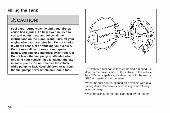
Filling the Tank
{CAUTION:
Fuel vapor burns violently and a fuel fire cancause bad injuries. To help avoid injuries toyou and others, read and follow all theinstructions on the pump island. Turn off yourengine when you are refueling. Do not smokeif you are near fuel or refueling your vehicle.Do not use cellular phones. Keep sparks,flames, and smoking materials away from fuel.Do not leave the fuel pump unattended whenrefueling your vehicle. This is against the lawin some places. Do not re-enter the vehiclewhile pumping fuel. Keep children away fromthe fuel pump; never let children pump fuel. The tethered fuel cap is located behind a hinged fuel
door on the driver’s side of the vehicle. If the vehiclehas E85 fuel capability, a yellow cap with the words“E85 or gasoline” can be seen.
When the fuel door is opened on a vehicle with dualsliding doors, the driver’s side sliding door will onlyopen partway.
While refueling, let the fuel cap hang by the tether.
5-8

{CAUTION:
Fuel can spray out on you if you open the fuelcap too quickly. If you spill fuel and thensomething ignites it, you could be badly burned.This spray can happen if your tank is nearly full,and is more likely in hot weather. Open the fuelcap slowly and wait for any hiss noise to stop.Then unscrew the cap all the way.
Be careful not to spill fuel. Do not top off or overfill thetank and wait a few seconds after you have finishedpumping before removing the nozzle. Clean fuelfrom painted surfaces as soon as possible.See Washing Your Vehicle on page 5-93.
When replacing the fuel cap, turn it clockwise until itclicks. Make sure the cap is fully installed. The diagnosticsystem can determine if the fuel cap has been left off orimproperly installed. This would allow fuel to evaporateinto the atmosphere. See Malfunction Indicator Lamp onpage 3-44.
The CHECK GAS CAP message will be displayed in theDriver Information Center (DIC) if the fuel cap is notproperly installed. See DIC Warnings and Messages onpage 3-58 for more information.
{CAUTION:
If a fire starts while you are refueling, do notremove the nozzle. Shut off the flow of fuel byshutting off the pump or by notifying thestation attendant. Leave the area immediately.
Notice: If you need a new fuel cap, be sure to getthe right type. Your dealer/retailer can get onefor you. If you get the wrong type, it may not fitproperly. This may cause your malfunction indicatorlamp to light and may damage your fuel tank andemissions system. See Malfunction Indicator Lampon page 3-44.
5-9

Filling a Portable Fuel Container
{CAUTION:
Never fill a portable fuel container while it isin your vehicle. Static electricity dischargefrom the container can ignite the fuel vapor.You can be badly burned and your vehicledamaged if this occurs. To help avoid injury toyou and others:
• Dispense fuel only into approvedcontainers.
• Do not fill a container while it is inside avehicle, in a vehicle’s trunk, pickup bed, oron any surface other than the ground.
• Bring the fill nozzle in contact with theinside of the fill opening before operatingthe nozzle. Contact should be maintaineduntil the filling is complete.
• Do not smoke while pumping fuel.• Do not use a cellular phone while
pumping fuel.
Checking Things Underthe Hood
{CAUTION:
An electric fan under the hood can start upand injure you even when the engine is notrunning. Keep hands, clothing, and tools awayfrom any underhood electric fan.
{CAUTION:
Things that burn can get on hot engine partsand start a fire. These include liquids like fuel,oil, coolant, brake fluid, windshield washer andother fluids, and plastic or rubber. You orothers could be burned. Be careful not to dropor spill things that will burn onto a hot engine.
5-10

Hood ReleaseTo open the hood, do the following:
1. Pull the hood releasehandle with thissymbol on it. It islocated underthe instrument panelon the driver’s side.
2. Go to the front of the vehicle and push theunderhood release to the right. It is located near thecenter of the hood, above the grille.
3. Lift the hood.
4. Pull up on the hood prop to release it from itsstorage clip.The hood prop may be hot due to increased enginetemperatures under the hood, so be careful whenhandling it. Use your hood prop sleeve whenhandling the hood prop.
5. Put the end of the hood prop into the slot in theunderside of the hood, on the driver’s side of thevehicle. It is marked by an arrow.
Before closing the hood, be sure all the filler caps areon properly. Lift the hood to relieve pressure on the hoodprop. Remove the hood prop from the slot in the hoodand return the prop to its retainer. Then let the hooddown and close it firmly.
5-11

Engine Compartment OverviewWhen you open the hood on the 3.9L V6 engine, here is what you will see:
5-12

A. Underhood Fuse Block. See Underhood Fuse Blockon page 5-102.
B. Remote Positive (+) Terminal. See Jump Starting onpage 5-37.
C. Windshield Washer Fluid Reservoir. See “AddingWasher Fluid” under Windshield Washer Fluidon page 5-32.
D. Radiator Pressure Cap. See Radiator Pressure Capon page 5-24.
E. Power Steering Fluid Reservoir. See Power SteeringFluid on page 5-31.
F. Engine Oil Fill Cap. See “When to Add Engine Oil”under Engine Oil on page 5-13.
G. Engine Oil Dipstick. See “Checking Engine Oil”under Engine Oil on page 5-13.
H. Automatic Transmission Fluid Dipstick. See“Checking the Fluid Level” under AutomaticTransmission Fluid on page 5-20.
I. Brake Master Cylinder Reservoir. See “Brake Fluid”under Brakes on page 5-33.
J. Engine Air Cleaner/Filter. See Engine AirCleaner/Filter on page 5-18.
K. Engine Coolant Recovery Tank. See Cooling Systemon page 5-26.
Engine Oil
Checking Engine OilIt is a good idea to check the engine oil every time youget fuel. In order to get an accurate reading, the oilmust be warm and the vehicle must be on level ground.
The engine oil dipstick handle is a yellow loop.See Engine Compartment Overview on page 5-12for the location of the engine oil dipstick.
1. Turn off the engine and give the oil several minutesto drain back into the oil pan. If you do not do this,the oil dipstick might not show the actual level.
2. Pull out the dipstick and clean it with a paper towelor cloth, then push it back in all the way. Remove itagain, keeping the tip down, and check the level.
5-13

When to Add Engine Oil
If the oil is below the cross-hatched area at the tipof the dipstick, add at least one quart/liter of therecommended oil. This section explains what kind ofoil to use. For engine oil crankcase capacity, seeCapacities and Specifications on page 5-105.
Notice: Do not add too much oil. If the enginehas so much oil that the oil level gets above thecross-hatched area that shows the proper operatingrange, the engine could be damaged.
See Engine CompartmentOverview on page 5-12for the location of theengine oil fill cap.
Be sure to add enough oil to put the level somewhere inthe proper operating range in the cross-hatched area.Push the dipstick all the way back in when you arethrough.
5-14

What Kind of Engine Oil to Use
Look for three things:
• GM6094M
Your vehicle’s engine requires oil meetingGM Standard GM6094M. Look for and use onlyan oil that meets GM Standard GM6094M.
• SAE 5W-30As shown in the viscosity chart, SAE 5W-30 is bestfor your vehicle.These numbers on an oil container show itsviscosity, or thickness. Do not use other viscosityoils such as SAE 20W-50.
• Oils meeting theserequirements shouldhave the starburstsymbol on the container.This symbol indicatesthat the oil hasbeen certified by theAmerican PetroleumInstitute (API).
Look for this information on the oil container, anduse only those oils that are identified as meetingGM Standard GM6094M and have the starburst symbolon the front of the oil container.
Notice: Use only engine oil identified as meetingGM Standard GM6094M and showing the AmericanPetroleum Institute Certified For Gasoline Enginesstarburst symbol. Failure to use the recommendedoil can result in engine damage not covered byyour warranty.
5-15

If you are in an area of extreme cold, where thetemperature falls below −20°F (−29°C), it isrecommended that you use either an SAE 5W-30synthetic oil or an SAE 0W-30 oil. Both provide easiercold starting and better protection for the engine atextremely low temperatures.
Engine Oil AdditivesDo not add anything to the oil. The recommended oilswith the starburst symbol meet GM Standard GM6094Mare all you need for good performance and engineprotection.
Engine Oil Life System
When to Change Engine OilYour vehicle has a computer system that lets you knowwhen to change the engine oil and filter. This is basedon engine revolutions and engine temperature, andnot on mileage. Based on driving conditions, the mileageat which an oil change will be indicated can varyconsiderably. For the oil life system to work properly,you must reset the system every time the oil is changed.
When the system has calculated that oil life has beendiminished, it will indicate that an oil change isnecessary. A CHANGE OIL SOON message will comeon. See DIC Warnings and Messages on page 3-58.Change the oil as soon as possible within the next600 miles (1 000 km). It is possible that, if youare driving under the best conditions, the oil life systemmight not indicate that an oil change is necessary forover a year. However, the engine oil and filter must bechanged at least once a year and at this time thesystem must be reset. Your dealer/retailer has trainedpeople who will perform this work using genuineparts and reset the system. It is also important to checkthe oil regularly and keep it at the proper level.
If the system is ever reset accidentally, you must changethe oil at 3,000 miles (5 000 km) since your last oilchange. Remember to reset the oil life system wheneverthe oil is changed.
5-16

How to Reset the Engine Oil LifeSystemThe Engine Oil Life System calculates when tochange the engine oil and filter based on vehicle use.Whenever the oil is changed, reset the system so it cancalculate when the next oil change is required. If asituation occurs where you change the oil prior toa CHANGE OIL SOON message being turned on,reset the system.
1. With the ignition key in ON/RUN but the engine off,repeatedly push the set/reset button until OIL isdisplayed on the Driver Information Center (DIC).
2. Once OIL is displayed, push and hold the set/resetbutton for five seconds. The number will disappearand be replaced by 100 (indicating 100% oil liferemaining).
3. Turn the key to LOCK/OFF.
If the CHANGE OIL SOON message comes back onwhen you start your vehicle, the engine oil life systemhas not reset. Repeat the procedure.
What to Do with Used OilUsed engine oil contains certain elements that can beunhealthy for your skin and could even cause cancer.Do not let used oil stay on your skin for very long.Clean your skin and nails with soap and water, or agood hand cleaner. Wash or properly dispose ofclothing or rags containing used engine oil. See themanufacturer’s warnings about the use and disposal ofoil products.
Used oil can be a threat to the environment. If youchange your own oil, be sure to drain all the oil from thefilter before disposal. Never dispose of oil by putting itin the trash, pouring it on the ground, into sewers, or intostreams or bodies of water. Instead, recycle it bytaking it to a place that collects used oil. If you have aproblem properly disposing of used oil, ask yourdealer/retailer, a service station, or a local recyclingcenter for help.
5-17

Engine Air Cleaner/Filter
See Engine Compartment Overview on page 5-12 forthe location of the engine air cleaner/filter.
When to Inspect the EngineAir Cleaner/FilterInspect the air cleaner/filter at the Maintenance IIintervals and replace it at the first oil change after each50,000 mile (85 000 km) interval. See ScheduledMaintenance on page 6-4 for more information. If youare driving in dusty/dirty conditions, inspect the filterat each engine oil change.
How to Inspect the EngineAir Cleaner/FilterTo inspect the air cleaner/filter, remove the filter fromthe vehicle and lightly shake the filter to releaseloose dust and dirt. If the filter remains caked with dirt,a new filter is required. Do not use compressed airto clean the filter.
5-18

To inspect or replace the air cleaner/filter, do thefollowing:
1. Remove the two clamps on the duct.
2. Remove the duct.
3. Unlatch the two hooks on top of the engine aircleaner/filter housing.
4. Inspect or replace the engine air cleaner/filter.
5. Align the tabs located on the bottom of the panelwith the slots at the bottom of the housing.
6. Latch the hooks to secure the panel in place. If thepanel moves easily, check that the tabs are seatedcorrectly in the slots.
7. Put the duct back on and reinstall the clamps.
{CAUTION:
Operating the engine with the air cleaner/filteroff can cause you or others to be burned.The air cleaner not only cleans the air; it helpsto stop flames if the engine backfires. If it isnot there and the engine backfires, you couldbe burned. Do not drive with it off, and becareful working on the engine with the aircleaner/filter off.
Notice: If the air cleaner/filter is off, a backfire cancause a damaging engine fire. And, dirt caneasily get into your engine, which will damage it.Always have the air cleaner/filter in place when youare driving.
5-19

Automatic Transmission Fluid
When to Check and Change AutomaticTransmission FluidA good time to check your automatic transmission fluidlevel is when the engine oil is changed.
Change the fluid and filter at the intervals listed inAdditional Required Services on page 6-6, and be sureto use the transmission fluid listed in RecommendedFluids and Lubricants on page 6-11.
How to Check AutomaticTransmission FluidBecause this operation can be a little difficult, you maychoose to have this done at the dealer/retailer servicedepartment.
If you do it yourself, be sure to follow all the instructionshere, or you could get a false reading on the dipstick.
Notice: Too much or too little fluid can damageyour transmission. Too much can mean that someof the fluid could come out and fall on hot engineparts or exhaust system parts, starting a fire.Too little fluid could cause the transmission tooverheat. Be sure to get an accurate reading if youcheck your transmission fluid.
Wait at least 30 minutes before checking thetransmission fluid level if you have been driving:
• When outside temperatures are above 90°F (32°C).
• At high speed for quite a while.
• In heavy traffic — especially in hot weather.
• While pulling a trailer.
To get the right reading, the fluid should be at normaloperating temperature, which is 180°F to 200°F(82°C to 93°C).
Get the vehicle warmed up by driving about 15 miles(24 km) when outside temperatures are above50°F (10°C). If it is colder than 50°F (10°C), you mayhave to drive longer.
5-20

Checking the Fluid LevelPrepare your vehicle as follows:1. Park your vehicle on a level place. Keep the engine
running.2. With the parking brake applied, place the shift lever
in PARK (P).3. With your foot on the brake pedal, move the shift
lever through each gear range, pausing for aboutthree seconds in each range. Then, position theshift lever in PARK (P).
4. Let the engine run at idle for three to five minutes.
Then, without shutting off the engine, follow these steps:1. Pull out the dipstick and wipe it with a clean rag or
paper towel.The automatic transmission dipstick is located towardthe back of the engine compartment, near the brakemaster cylinder reservoir. The dipstick handle is ared loop. See Engine Compartment Overview onpage 5-12 for more information on location.
2. Push it back in all the way, wait three seconds, andthen pull it back out again.
3. Check both sides of the dipstick, and read thelower level. The fluid level must be in thecross-hatched area.
4. If the fluid level is in the acceptable range,push the dipstick back in all the way.
How to Add AutomaticTransmission FluidRefer to the Maintenance Schedule to determine whatkind of transmission fluid to use. See RecommendedFluids and Lubricants on page 6-11.
If the fluid level is low, add only enough of the properfluid to bring the level into the cross-hatched area onthe dipstick.1. Pull out the dipstick.2. Using a long-neck funnel, add enough fluid at the
dipstick hole to bring it to the proper level.It does not take much fluid, generally less thanone pint (0.5 L). Do not overfill.
Notice: Use of the incorrect automatic transmissionfluid may damage your vehicle, and the damagesmay not be covered by your warranty. Alwaysuse the automatic transmission fluid listed inRecommended Fluids and Lubricants on page 6-11.
3. After adding fluid, recheck the fluid level asdescribed under “How to Check AutomaticTransmission Fluid,” earlier in this section.
4. When the correct fluid level is obtained, push thedipstick back in all the way.
5-21

Engine CoolantThe cooling system in your vehicle is filled withDEX-COOL® engine coolant. This coolant is designedto remain in your vehicle for five years or 150,000 miles(240 000 km), whichever occurs first, if you add onlyDEX-COOL® extended life coolant.
The following explains your cooling system and how toadd coolant when it is low. If you have a problemwith engine overheating, see Engine Overheating onpage 5-24.
A 50/50 mixture of clean, drinkable water andDEX-COOL® coolant will:• Give freezing protection down to −34°F (−37°C).• Give boiling protection up to 265°F (129°C).• Protect against rust and corrosion.• Help keep the proper engine temperature.• Let the warning messages and gages work as
they should.
Notice: Using coolant other than DEX-COOL® maycause premature engine, heater core, or radiatorcorrosion. In addition, the engine coolant mayrequire changing sooner, at the first maintenanceservice after each 30,000 miles (50 000 km) or24 months, whichever occurs first. Any repairswould not be covered by your warranty. Always useDEX-COOL® (silicate-free) coolant in your vehicle.
What Engine Coolant to UseUse a mixture of one-half clean, drinkable water andone-half DEX-COOL® coolant which will not damagealuminum parts. If you use this coolant mixture, you donot need to add anything else.
{CAUTION:
Adding only plain water to your coolingsystem can be dangerous. Plain water, orsome other liquid such as alcohol, can boilbefore the proper coolant mixture will. Yourvehicle’s coolant warning system is set for theproper coolant mixture. With plain water or thewrong mixture, your engine could get too hotbut you would not get the overheat warning.Your engine could catch fire and you or otherscould be burned. Use a 50/50 mixture of clean,drinkable water and DEX-COOL® coolant.
Notice: If you use an improper coolant mixture,your engine could overheat and be badly damaged.The repair cost would not be covered by yourwarranty. Too much water in the mixture can freezeand crack the engine, radiator, heater core, andother parts.
5-22

If you have to add coolant more than four times a year,have your dealer/retailer check your cooling system.
Notice: If you use extra inhibitors and/or additivesin your vehicle’s cooling system, you coulddamage your vehicle. Use only the proper mixtureof the engine coolant listed in this manual forthe cooling system. See Recommended Fluids andLubricants on page 6-11 for more information.
Checking CoolantThe coolant recovery tankis located on the driver’sside of the vehicle,above the engine aircleaner/filter. See EngineCompartment Overviewon page 5-12 for moreinformation on location.
The vehicle must be on a level surface. When yourengine is cold, the coolant level should be at the full coldmark, or a little higher. When your engine is warm, thelevel should be above the full cold mark or a little higher.The full cold mark is a line with an arrow pointing down atit, located on the front of the coolant recovery tank.
Adding CoolantIf you need more coolant, add the proper DEX-COOL®
coolant mixture at the coolant recovery tank, but becareful not to spill it.
{CAUTION:
Turning the radiator pressure cap when theengine and radiator are hot can allow steamand scalding liquids to blow out and burn youbadly. With the coolant recovery tank, you willalmost never have to add coolant at theradiator. Never turn the radiator pressurecap — even a little — when the engine andradiator are hot.
{CAUTION:
You can be burned if you spill coolant on hotengine parts. Coolant contains ethylene glycol,and it will burn if the engine parts are hotenough. Do not spill coolant on a hot engine.
5-23

Occasionally check the coolant level in the radiator.For information on how to add coolant to the radiator,see Cooling System on page 5-26.
Radiator Pressure CapNotice: The radiator cap on your vehicle is apressure-type cap and must be tightly installed toprevent coolant loss and possible engine damagefrom overheating. Be sure the cap is properlyclosed.
See Engine Compartment Overview on page 5-12for more information on location.
Engine OverheatingYou will find an engine coolant temperature gage onyour vehicle’s instrument panel. See Engine CoolantTemperature Gage on page 3-43.
Your vehicle may also have an ENGINE COOLANTHOT message displayed in the Driver InformationCenter (DIC). See DIC Warnings and Messages onpage 3-58.
If Steam Is Coming From Your Engine
{CAUTION:
Steam from an overheated engine can burnyou badly, even if you just open the hood.Stay away from the engine if you see or hearsteam coming from it. Turn it off and geteveryone away from the vehicle until it coolsdown. Wait until there is no sign of steam orcoolant before you open the hood.If you keep driving when the vehicles engineis overheated, the liquids in it can catch fire.You or others could be badly burned. Stopyour engine if it overheats, and get out of thevehicle until the engine is cool.
See Overheated Engine Protection OperatingMode on page 5-25 for information on drivingto a safe place in an emergency.
Notice: If your engine catches fire because you keepdriving with no coolant, your vehicle can be badlydamaged. The costly repairs would not be covered byyour warranty. See Overheated Engine ProtectionOperating Mode on page 5-25 for information ondriving to a safe place in an emergency.
5-24

If No Steam Is Coming From YourEngineIf you get an engine overheat warning but see or hearno steam, the problem may not be too serious.Sometimes the engine can get a little too hot when you:• Climb a long hill on a hot day.• Stop after high-speed driving.• Idle for long periods in traffic.• Tow a trailer.
If you get the overheat warning with no sign of steam,try this for a minute or so:
1. If your air conditioner is on, turn it off.
2. Turn on your heater to full hot at the highest fanspeed and open the windows as necessary.
3. If you are in a traffic jam, shift to NEUTRAL (N);otherwise, shift to the highest gear whiledriving — DRIVE (D) or THIRD (3).
If you no longer have the overheat warning, you candrive. Just to be safe, drive slower for about 10 minutes.If the warning does not come back on, you can drivenormally.
If the warning continues, pull over, stop, and park yourvehicle right away.
If there is still no sign of steam, idle the engine forthree minutes while you are parked. If you still have thewarning, turn off the engine and get everyone out ofthe vehicle until it cools down. Also, see “OverheatedEngine Protection Operating Mode” later in this section.
You may decide not to lift the hood but to get servicehelp right away.
Overheated Engine ProtectionOperating ModeThis emergency operating mode lets your vehicle bedriven to a safe place in an emergency situation.If an overheated engine condition exists, an overheatprotection mode which alternates firing groups ofcylinders helps prevent engine damage. In this mode,there is a significant loss in power and engineperformance. The temperature gage indicates anoverheat condition exists. Driving extended distancesand/or towing a trailer in the overheat protectionmode should be avoided.
Notice: After driving in the overheated engineprotection operating mode, to avoid engine damage,allow the engine to cool before attempting any repair.The engine oil will be severely degraded. Repair thecause of coolant loss, change the oil and reset theoil life system. See Engine Oil on page 5-13.
5-25

Cooling SystemWhen you decide it is safe to lift the hood, here is whatyou will see:
A. RadiatorPressure Cap
B. Electric EngineCooling Fans
C. Engine CoolantRecovery Tank
D. Recovery tankFULL COLD mark
{CAUTION:
An electric engine cooling fan under the hoodcan start up even when the engine is notrunning and can injure you. Keep hands,clothing, and tools away from any underhoodelectric fan.
If the coolant inside the coolant recovery tank is boiling,do not do anything else until it cools down. The vehicleshould be parked on a level surface.
The coolant level should be at or above the full coldmark. If it is not, you may have a leak at the pressurecap or in the radiator hoses, heater hoses, radiator,water pump, or somewhere else in the cooling system.
5-26

{CAUTION:
Heater and radiator hoses, and other engineparts, can be very hot. Do not touch them.If you do, you can be burned.
Do not run the engine if there is a leak. If yourun the engine, it could lose all coolant.That could cause an engine fire, and you couldbe burned. Get any leak fixed before you drivethe vehicle.
If there seems to be no leak, with the engine on, checkto see if the electric engine cooling fans are running.If the engine is overheating, both fans should berunning. If they are not, your vehicle needs service.
Notice: Engine damage from running your enginewithout coolant is not covered by your warranty.See Overheated Engine Protection Operating Modeon page 5-25 for information on driving to a safeplace in an emergency.
Notice: Using coolant other than DEX-COOL® maycause premature engine, heater core, or radiatorcorrosion. In addition, the engine coolant couldrequire changing sooner, at 30,000 miles (50 000 km)or 24 months, whichever occurs first. Any repairswould not be covered by the warranty. Always useDEX-COOL® (silicate-free) coolant in the vehicle.
5-27

How to Add Coolant to the CoolantRecovery TankIf you have not found a problem yet, but the coolantlevel is not at or above the full cold mark, add a 50/50mixture of clean, drinkable water and DEX-COOL®
engine coolant at the coolant recovery tank. See EngineCoolant on page 5-22 for more information.
{CAUTION:
Adding only plain water to the cooling systemcan be dangerous. Plain water, or some otherliquid such as alcohol, can boil before theproper coolant mixture will. The vehicle’scoolant warning system is set for the propercoolant mixture. With plain water or the wrongmixture, the engine could get too hot but youwould not get the overheat warning. The enginecould catch fire and you or others could beburned. Use a 50/50 mixture of clean, drinkablewater and DEX-COOL® coolant.
Notice: In cold weather, water can freeze and crackthe engine, radiator, heater core and other parts.Use the recommended coolant and the propercoolant mixture.
{CAUTION:
You can be burned if you spill coolant on hotengine parts. Coolant contains ethylene glycoland it will burn if the engine parts are hotenough. Do not spill coolant on a hot engine.
When the coolant in the coolant recovery tank is at orabove the full cold mark, start your vehicle.
5-28

If the overheat warning continues, there is one morething you can try. You can add the proper coolantmixture directly to the radiator, but be sure the coolingsystem is cool before you do it.
{CAUTION:
Steam and scalding liquids from a hot coolingsystem can blow out and burn you badly.They are under pressure, and if you turn theradiator pressure cap — even a little — theycan come out at high speed. Never turn thecap when the cooling system, including theradiator pressure cap, is hot. Wait for thecooling system and radiator pressure cap tocool if you ever have to turn the pressure cap.
How to Add Coolant to the RadiatorNotice: Your engine has a specific radiator fillprocedure. Failure to follow this procedure couldcause your engine to overheat and be severelydamaged.
1. You can remove theradiator pressure capwhen the coolingsystem, including theradiator pressurecap and upper radiatorhose, is no longer hot.
Turn the pressure cap slowly counterclockwise.If you hear a hiss, wait for that to stop. A hissmeans there is still some pressure left, close thecap and wait for the system to cool down.
2. Keep turning the pressure cap. Remove thepressure cap.
5-29

{CAUTION:
You can be burned if you spill coolant on hotengine parts. Coolant contains ethylene glycoland it will burn if the engine parts are hotenough. Do not spill coolant on a hot engine.
3. Fill the radiator with the proper DEX-COOL®
coolant mixture, up to the base of the fillerneck. See Engine Coolant on page 5-22 for moreinformation about the proper coolant mixture.
4. Rinse or wipe any spilled coolant from the engineand the compartment.
5. Start the engine and let it run until you can feel theupper radiator hose getting hot. Watch out for theengine cooling fans.
6. By this time, the coolant level inside the radiatorfiller neck may be lower. If the level is lower, addmore of the proper DEX-COOL® coolant mixturethrough the filler neck until the level reachesthe base of the filler neck.
7. Then replace the pressure cap. At any time duringthis procedure if coolant begins to flow out of thefiller neck, reinstall the pressure cap. Be surethe pressure cap is closed properly.
8. Then fill the coolant recovery tank to thefull cold mark.
9. Put the cap back on the coolant recovery tank.
Filling the Coolant Recovery Tank
5-30

Power Steering FluidThe power steering fluidreservoir is located towardthe rear of the enginecompartment on thepassenger’s side of thevehicle. See EngineCompartment Overviewon page 5-12 for reservoirlocation.
When to Check Power Steering FluidIt is not necessary to regularly check power steering fluidunless you suspect there is a leak in the system oryou hear an unusual noise. A fluid loss in this systemcould indicate a problem. Have the system inspectedand repaired.
How to Check Power Steering FluidTo check the power steering fluid, do the following:
1. Turn the key off and let the engine compartmentcool down.
2. Wipe the cap and the top of the reservoir clean.
3. Unscrew the cap and wipe the dipstick with aclean rag.
4. Replace the cap and completely tighten it.
5. Remove the cap again and look at the fluid level onthe dipstick.
The fluid level should be somewhere within thecross-hatched area on the dipstick. If the fluid is atthe ADD mark, you should add fluid.
What to UseTo determine what kind of fluid to use, seeRecommended Fluids and Lubricants on page 6-11.Always use the proper fluid.
Notice: Use of the incorrect fluid may damage yourvehicle and the damages may not be covered byyour warranty. Always use the correct fluid listed inRecommended Fluids and Lubricants on page 6-11.
5-31

Windshield Washer Fluid
What Washer Fluid to UseWhen you need windshield washer fluid, be sure to readthe manufacturer’s instructions before use. If you willbe operating your vehicle in an area where thetemperature may fall below freezing, use a fluid that hassufficient protection against freezing.
Adding Washer Fluid
Open the cap with thewasher symbol on it.Add washer fluid until thetank is full. See EngineCompartment Overviewon page 5-12 for reservoirlocation.
Notice:
• When using concentrated washer fluid, followthe manufacturer’s instructions for addingwater.
• Do not mix water with ready-to-use washer fluid.Water can cause the solution to freeze anddamage your washer fluid tank and other partsof the washer system. Also, water does notclean as well as washer fluid.
• Fill the washer fluid tank only three-quarters fullwhen it is very cold. This allows for fluidexpansion if freezing occurs, which coulddamage the tank if it is completely full.
• Do not use engine coolant (antifreeze) in yourwindshield washer. It can damage the vehicle’swindshield washer system and paint.
5-32

Brakes
Brake FluidThe brake master cylinderreservoir is filled withDOT-3 brake fluid.See Engine CompartmentOverview on page 5-12for the location of thereservoir.
There are only two reasons why the brake fluid level inthe reservoir might go down. The first is that thebrake fluid goes down to an acceptable level duringnormal brake lining wear. When new linings are put in,the fluid level goes back up. The other reason isthat fluid is leaking out of the brake hydraulic system.If it is, you should have the brake hydraulic system fixed,since a leak means that sooner or later the brakeswill not work well.
It is not a good idea to top off the brake fluid. Addingbrake fluid will not correct a leak. If fluid is added whenthe linings are worn, there will be too much fluidwhen new brake linings are installed. Add or removebrake fluid, as necessary, only when work is done on thebrake hydraulic system.
{CAUTION:
If your vehicle has too much brake fluid, it canspill on the engine. The fluid will burn if theengine is hot enough. You or others could beburned, and your vehicle could be damaged.Add brake fluid only when work is done on thebrake hydraulic system.
When the brake fluid falls to a low level, the brakewarning light comes on. See Brake System WarningLight on page 3-41.
5-33

What to AddWhen you need brake fluid, use only DOT-3 brake fluid.Use new brake fluid from a sealed container only.See Recommended Fluids and Lubricants on page 6-11.
Always clean the brake fluid reservoir cap and thearea around the cap before removing it. This helps keepdirt from entering the reservoir.
{CAUTION:
With the wrong kind of fluid in the brakehydraulic system, the brakes might not workwell. This could cause a crash. Always use theproper brake fluid.
Notice:
• Using the wrong fluid can badly damage brakehydraulic system parts. For example, just afew drops of mineral-based oil, such as engineoil, in the brake hydraulic system can damagebrake hydraulic system parts so badly that theywill have to be replaced. Do not let someoneput in the wrong kind of fluid.
• If you spill brake fluid on your vehicle’s paintedsurfaces, the paint finish can be damaged.Be careful not to spill brake fluid on yourvehicle. If you do, wash it off immediately.See Washing Your Vehicle on page 5-93.
5-34

Brake WearYour vehicle has disc brakes. Disc brake pads havebuilt-in wear indicators that make a high-pitched warningsound when the brake pads are worn and new padsare needed. The sound can come and go or be heard allthe time your vehicle is moving, except when you arepushing on the brake pedal firmly.
{CAUTION:
The brake wear warning sound means thatsoon the brakes will not work well. That couldlead to an accident. When you hear the brakewear warning sound, have your vehicleserviced.
Notice: Continuing to drive with worn-out brakepads could result in costly brake repair.
Some driving conditions or climates can cause a brakesqueal when the brakes are first applied or lightlyapplied. This does not mean something is wrong withthe brakes.
Properly torqued wheel nuts are necessary to helpprevent brake pulsation. When tires are rotated, inspectbrake pads for wear and evenly tighten wheel nuts inthe proper sequence to torque specifications inCapacities and Specifications on page 5-105.
Brake linings should always be replaced as completeaxle sets.
Brake Pedal TravelSee your dealer/retailer if the brake pedal does notreturn to normal height, or if there is a rapid increase inpedal travel. This could be a sign that brake servicemight be required.
Brake AdjustmentEvery time you apply the brakes, with or without thevehicle moving, the brakes adjust for wear.
5-35

Replacing Brake System PartsThe braking system on a vehicle is complex. Its manyparts have to be of top quality and work well together ifthe vehicle is to have really good braking. Your vehiclewas designed and tested with top-quality brake parts.When you replace parts of the braking system — forexample, when the brake linings wear down and youneed new ones put in — be sure you get new approvedreplacement parts. If you do not, the brakes might notwork properly. For example, if someone puts in brakelinings that are wrong for your vehicle, the balancebetween the front and rear brakes can change — for theworse. The braking performance you have come toexpect can change in many other ways if someone putsin the wrong replacement brake parts.
BatteryYour vehicle has a maintenance free battery. When it istime for a new battery, see your dealer/retailer for onethat has the replacement number shown on the originalbattery’s label.
For battery replacement, see your dealer/retailer or theservice manual. To purchase a service manual, seeService Publications Ordering Information on page 7-15.
Warning: Battery posts, terminals, and relatedaccessories contain lead and lead compounds,chemicals known to the State of California to causecancer and reproductive harm. Wash hands afterhandling.
Vehicle Storage
{CAUTION:
Batteries have acid that can burn you andgas that can explode. You can be badly hurt ifyou are not careful. See Jump Starting onpage 5-37 for tips on working around a batterywithout getting hurt.
Infrequent Usage: If you drive your vehicle infrequently,remove the black, negative (−) cable from the battery.This will help keep the battery from running down.
Extended Storage: For extended storage of your vehicle,remove the black, negative (−) cable from the batteryor use a battery trickle charger. This will help maintainthe charge of the battery over an extended periodof time.
5-36

Jump StartingIf your vehicle’s battery has run down, you may want touse another vehicle and some jumper cables to startyour vehicle. Be sure to use the following steps todo it safely.
On vehicles equipped with the optional power slidingdoor, a low-voltage battery or replacing a batterymay cause the system to become inoperative.See Power Sliding Door (PSD) on page 2-16 formore information.
{CAUTION:
Batteries can hurt you. They can be dangerousbecause:
• They contain acid that can burn you.• They contain gas that can explode or
ignite.• They contain enough electricity to
burn you.
If you do not follow these steps exactly, someor all of these things can hurt you.
Notice: Ignoring these steps could result in costlydamage to your vehicle that would not be coveredby your warranty.
Trying to start your vehicle by pushing or pulling itwill not work, and it could damage your vehicle.
1. Check the other vehicle. It must have a 12-voltbattery with a negative ground system.
Notice: If the other vehicle’s system is not a 12-voltsystem with a negative ground, both vehicles canbe damaged. Only use vehicles with 12-volt systemswith negative grounds to jump start your vehicle.
2. Get the vehicles close enough so the jumper cablescan reach, but be sure the vehicles are not touchingeach other. If they are, it could cause a groundconnection you do not want. You would not be ableto start your vehicle, and the bad groundingcould damage the electrical systems.To avoid the possibility of the vehicles rolling, setthe parking brake firmly on both vehicles involvedin the jump start procedure. Put an automatictransaxle in PARK (P) or a manual transaxle inNEUTRAL before setting the parking brake.
5-37

Notice: If you leave your radio or other accessorieson during the jump starting procedure, they couldbe damaged. The repairs would not be coveredby your warranty. Always turn off your radio andother accessories when jump starting your vehicle.
3. Turn off the ignition on both vehicles. Unplugunnecessary accessories plugged into the cigarettelighter or the accessory power outlet. Turn offthe radio and all lamps that are not needed.This will avoid sparks and help save both batteries.And it could save the radio!
4. Open the hoods and locate the batteries. Find thepositive (+) and negative (−) terminal locations oneach vehicle.You will not need to access your battery for jumpstarting. Your vehicle has a remote positive (+) jumpstarting terminal for that purpose.
The terminal is locatedunder the fuse block cover.Remove the cover toaccess the remotepositive (+) terminal.
See Engine Compartment Overview on page 5-12for more information on the location of theremote positive (+) terminal. You should alwaysuse the remote positive (+) terminal instead of thepositive (+) terminal on your battery.
{CAUTION:
An electric fan can start up even when theengine is not running and can injure you.Keep hands, clothing and tools away from anyunderhood electric fan.
5-38

{CAUTION:
Using a match near a battery can cause batterygas to explode. People have been hurt doingthis, and some have been blinded. Use aflashlight if you need more light.
Be sure the battery has enough water. You donot need to add water to the battery installedin your new vehicle. But if a battery has fillercaps, be sure the right amount of fluid is there.If it is low, add water to take care of that first.If you do not, explosive gas could be present.
Battery fluid contains acid that can burn you.Do not get it on you. If you accidentally get itin your eyes or on your skin, flush the placewith water and get medical help immediately.
{CAUTION:
Fans or other moving engine parts can injureyou badly. Keep your hands away from movingparts once the engine is running.
5. Check that the jumper cables do not have loose ormissing insulation. If they do, you could get ashock. The vehicles could be damaged too.Before you connect the cables, here are somebasic things you should know. Positive (+) will go topositive (+) or to a remote positive (+) terminal ifthe vehicle has one. Negative (−) will go to a heavy,unpainted metal engine part or to a remotenegative (−) terminal if the vehicle has one. Do notconnect positive (+) to negative (−) or you willget a short that would damage the battery andmaybe other parts too. Do not connect thenegative (−) cable to the negative (−) terminal onthe dead battery because this can cause sparks.
6. Connect the red positive (+) cable to the positive (+)terminal of the dead battery. Use a remotepositive (+) terminal if the vehicle has one.
5-39
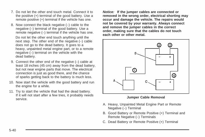
7. Do not let the other end touch metal. Connect it tothe positive (+) terminal of the good battery. Use aremote positive (+) terminal if the vehicle has one.
8. Now connect the black negative (−) cable to thenegative (−) terminal of the good battery. Use aremote negative (−) terminal if the vehicle has one.Do not let the other end touch anything until thenext step. The other end of the negative (−) cabledoes not go to the dead battery. It goes to aheavy, unpainted metal engine part, or to a remotenegative (−) terminal on the vehicle with thedead battery.
9. Connect the other end of the negative (−) cable atleast 18 inches (45 cm) away from the dead battery,but not near engine parts that move. The electricalconnection is just as good there, and the chanceof sparks getting back to the battery is much less.
10. Now start the vehicle with the good battery and runthe engine for a while.
11. Try to start the vehicle that had the dead battery.If it will not start after a few tries, it probably needsservice.
Notice: If the jumper cables are connected orremoved in the wrong order, electrical shorting mayoccur and damage the vehicle. The repairs wouldnot be covered by your warranty. Always connectand remove the jumper cables in the correctorder, making sure that the cables do not toucheach other or other metal.
A. Heavy, Unpainted Metal Engine Part or RemoteNegative (−) Terminal
B. Good Battery or Remote Positive (+) Terminal andRemote Negative (−) Terminals
C. Dead Battery or Remote Positive (+) Terminal
Jumper Cable Removal
5-40

To disconnect the jumper cables from both vehicles,do the following:
1. Disconnect the black negative (−) cable from thevehicle that had the dead battery.
2. Disconnect the black negative (−) cable from thevehicle with the good battery.
3. Disconnect the red positive (+) cable from thevehicle with the good battery.
4. Disconnect the red positive (+) cable from the othervehicle.
5. Return the remote positive (+) terminal cover orunderhood fuse block cover to its original position.
Headlamp AimingHeadlamp aim has been preset at the factory andshould need no further adjustment.
However, if your vehicle is damaged in a crash, theheadlamp aim may be affected. Aim adjustment to thelow-beam headlamps may be necessary if oncomingdrivers flash their high-beam headlamps at you(for vertical aim).
If the headlamps need to be re-aimed, it isrecommended that you take the vehicle to yourdealer/retailer for service.
5-41

Bulb ReplacementFor the proper type of replacement bulbs, seeReplacement Bulbs on page 5-46.
For any bulb changing procedure not listed in thissection, contact your dealer/retailer.
Halogen Bulbs
{CAUTION:
Halogen bulbs have pressurized gas inside andcan burst if you drop or scratch the bulb. You orothers could be injured. Be sure to read andfollow the instructions on the bulb package.
Headlamps and Sidemarker Lamps
A. High-beam HeadlampB. Low-beam HeadlampC. Sidemarker Lamp
5-42

To replace one of these bulbs:
1. Open the hood. See Hood Release on page 5-11for more information.
2. Remove the headlamp retainer pin (A) by turning ittowards the headlamp assembly and pulling itstraight out.
3. Remove the screw (B) from the top of the headlampassembly.
4. Pull the assembly away from the vehicle.
5. Disconnect the socket wiring harness connectorfrom the headlamp assembly.
6. Turn the bulb socket counterclockwise to removefrom the assembly.
7. To replace a headlamp bulb, disconnect the bulbsocket wiring harness and connect to the newbulb socket.To replace a sidemarker bulb, pull the old bulb outand push a new bulb in.
8. Reinstall the bulb socket by inserting into the bulbassembly and turning it clockwise to secure.
9. Reverse the steps to reinstall the headlampassembly.
5-43

Front Turn Signal, Parking andDaytime Running Lamps (DRL)
To replace one of these bulbs (A):
1. Follow the Steps 1 through 4 to remove theheadlamp assembly. See Headlamps andSidemarker Lamps on page 5-42 for moreinformation.
2. Turn the bulb socket counterclockwise to removefrom the assembly.
3. Pull the old bulb out from the bulb socket.4. Replace with a new bulb5. Reinstall the bulb socket by inserting into the bulb
assembly and turning it clockwise to secure.6. Reverse the steps to reinstall the headlamp
assembly.
Taillamps, Turn Signal, Stoplampsand Back-up LampsTo change a stoplamp/taillamp, turn signal or back-uplamp bulb:
1. Open the liftgate. See Liftgate on page 2-22 formore information.
2. Remove the two screwsfrom the taillamphousing on theinboard side.
3. Pull out the taillamp housing.
4. Disconnect the wiring harness connector from thetaillamp assembly.
5-44
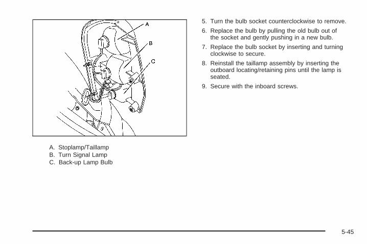
A. Stoplamp/TaillampB. Turn Signal LampC. Back-up Lamp Bulb
5. Turn the bulb socket counterclockwise to remove.
6. Replace the bulb by pulling the old bulb out ofthe socket and gently pushing in a new bulb.
7. Replace the bulb socket by inserting and turningclockwise to secure.
8. Reinstall the taillamp assembly by inserting theoutboard locating/retaining pins until the lamp isseated.
9. Secure with the inboard screws.
5-45

License Plate LampTo replace one of these bulbs:
1. Remove the two screws holding each of the licenseplate lamps to the fascia.
2. Turn and pull the license plate lamp forwardthrough the fascia opening.
3. Turn the bulb socket counterclockwise and pull thebulb straight out of the socket.
4. Install the new bulb.
5. Reverse Steps 1 through 3 to reinstall the licenseplate lamp.
Replacement Bulbs
Exterior Lamp Bulb Number
Back-up 3057KX
Front Turn Signal, DRL andParking 3157NAK
High-Beam and Low-BeamHeadlamps H11
License Plate Lamp 168
Sidemarker 194
Stoplamp, Taillamp andTurn Signal 3057KX
For replacement bulbs not listed here, contact yourdealer/retailer.
5-46

Windshield Wiper BladeReplacementWindshield wiper blades should be inspected for wearand cracking. See Scheduled Maintenance on page 6-4for more information.
Replacement blades come in different types and areremoved in different ways. For proper type and length,see Normal Maintenance Replacement Parts onpage 6-13.
To replace the windshield wiper blade assemblydo the following:
1. Lift the wiper arm and turn the bladeuntil it is facing away from thewindshield.
2. Squeeze the tabs (B) on each side of the wiperblade assembly to remove the wiper arm (A)from the blade (C).Allowing the wiper blade arm to touch the windshieldwhen no wiper blade is installed could damagethe windshield. Any damage that occurs would notbe covered by your warranty. Do not allow thewiper blade arm to touch the windshield.
3. Push the new wiper blade securely on the wiperarm until you hear the tabs on each side of thewiper blade assembly click into place.
To replace the rear wiper blade, follow the stepslisted above.
5-47

TiresYour new vehicle comes with high-quality tiresmade by a leading tire manufacturer. If you everhave questions about your tire warranty and whereto obtain service, see your vehicle Warrantybooklet for details.
{CAUTION:
• Poorly maintained and improperlyused tires are dangerous.
• Overloading your tires can causeoverheating as a result of too muchflexing. You could have an air-out anda serious accident. See Loading YourVehicle on page 4-21.
CAUTION: (Continued)
CAUTION: (Continued)
• Underinflated tires pose the samedanger as overloaded tires. Theresulting accident could cause seriousinjury. Check all tires frequently tomaintain the recommended pressure.Tire pressure should be checked whenyour tires are cold. See Inflation - TirePressure on page 5-54.
• Overinflated tires are more likely tobe cut, punctured, or broken by asudden impact — such as when youhit a pothole. Keep tires at therecommended pressure.
• Worn, old tires can cause accidents.If your tread is badly worn, or if yourtires have been damaged, replace them.
See High-Speed Operation on page 5-56for inflation pressure adjustment forhigh speed driving.
5-48

Tire Sidewall LabelingUseful information about a tire is molded into itssidewall. The examples below show a typicalpassenger vehicle tire and a compact spare tiresidewall.
(A) Tire Size: The tire size is a combination ofletters and numbers used to define a particulartire’s width, height, aspect ratio, construction type,and service description. See the “Tire Size”illustration later in this section for more detail.
(B) TPC Spec (Tire Performance CriteriaSpecification): Original equipment tires designedto GM’s specific tire performance criteria havea TPC specification code molded onto the sidewall.GM’s TPC specifications meet or exceed allfederal safety guidelines.
(C) DOT (Department of Transportation):The Department of Transportation (DOT) codeindicates that the tire is in compliance with theU.S. Department of Transportation Motor VehicleSafety Standards.
(D) Tire Identification Number (TIN): The lettersand numbers following DOT (Department ofTransportation) code is the Tire IdentificationNumber (TIN). The TIN shows the manufacturerand plant code, tire size, and date the tire wasmanufactured. The TIN is molded onto both sidesof the tire, although only one side may havethe date of manufacture.
(E) Tire Ply Material: The type of cord andnumber of plies in the sidewall and under thetread.
Passenger (P-Metric) Tire Example
5-49

(F) Uniform Tire Quality Grading (UTQG):Tire manufacturers are required to gradetires based on three performance factors:treadwear, traction, and temperature resistance.For more information see Uniform Tire QualityGrading on page 5-67.
(G) Maximum Cold Inflation Load Limit:Maximum load that can be carried and themaximum pressure needed to support that load.
(A) Temporary Use Only: The compact sparetire or temporary use tire has a tread life ofapproximately 3,000 miles (5 000 km) and shouldnot be driven at speeds over 65 mph (105 km/h).The compact spare tire is for emergency use whena regular road tire has lost air and gone flat. If yourvehicle has a compact spare tire, see CompactSpare Tire on page 5-89 and If a Tire Goes Flaton page 5-72.
(B) Tire Ply Material: The type of cord andnumber of plies in the sidewall and under thetread.
(C) Tire Identification Number (TIN): The lettersand numbers following the DOT (Department ofTransportation) code is the Tire IdentificationNumber (TIN). The TIN shows the manufacturerand plant code, tire size, and date the tirewas manufactured. The TIN is molded onto bothsides of the tire, although only one side may havethe date of manufacture.
(D) Maximum Cold Inflation Load Limit:Maximum load that can be carried and themaximum pressure needed to support that load.
(E) Tire Inflation: The temporary use tire orcompact spare tire should be inflated to 60 psi(420 kPa). For more information on tire pressureand inflation see Inflation - Tire Pressure onpage 5-54.
Compact Spare Tire Example
5-50

(F) Tire Size : A combination of letters andnumbers define a tire’s width, height, aspect ratio,construction type, and service description.The letter T as the first character in the tire sizemeans the tire is for temporary use only.
(G) TPC Spec (Tire Performance CriteriaSpecification): Original equipment tires designedto GM’s specific tire performance criteria havea TPC specification code molded onto the sidewall.GM’s TPC specifications meet or exceed allfederal safety guidelines.
Tire SizeThe following illustration shows an example of atypical passenger vehicle tire size.
(A) Passenger (P-Metric) Tire: The United Statesversion of a metric tire sizing system. The letter Pas the first character in the tire size means apassenger vehicle tire engineered to standards setby the U.S. Tire and Rim Association.
(B) Tire Width: The three-digit number indicatesthe tire section width in millimeters from sidewallto sidewall.
(C) Aspect Ratio: A two-digit number thatindicates the tire height-to-width measurements.For example, if the tire size aspect ratio is 60,as shown in item C of the illustration, it wouldmean that the tire’s sidewall is 60 percent as highas it is wide.
(D) Construction Code: A letter code is used toindicate the type of ply construction in the tire.The letter R means radial ply construction;the letter D means diagonal or bias plyconstruction; and the letter B means belted-biasply construction.
(E) Rim Diameter: Diameter of the wheel ininches.
(F) Service Description: These charactersrepresent the load range and speed rating of thetire. The load index represents the load carrycapacity a tire is certified to carry. The load indexcan range from 1 to 279. The speed rating isthe maximum speed a tire is certified to carry aload. Speed ratings range from A to Z.
5-51

Tire Terminology and DefinitionsAir Pressure: The amount of air inside thetire pressing outward on each square inch of thetire. Air pressure is expressed in pounds persquare inch (psi) or kilopascal (kPa).
Accessory Weight: This means the combinedweight of optional accessories. Some examples ofoptional accessories are, automatic transmission,power steering, power brakes, power windows,power seats, and air conditioning.
Aspect Ratio: The relationship of a tire’s heightto its width.
Belt: A rubber coated layer of cords that islocated between the plies and the tread. Cordsmay be made from steel or other reinforcingmaterials.
Bead: The tire bead contains steel wires wrappedby steel cords that hold the tire onto the rim.
Bias Ply Tire: A pneumatic tire in which the pliesare laid at alternate angles less than 90 degreesto the centerline of the tread.
Cold Tire Pressure: The amount of air pressurein a tire, measured in pounds per square inch(psi) or kilopascals (kPa) before a tire has built upheat from driving. See Inflation - Tire Pressureon page 5-54.
Curb Weight: The weight of a motor vehicle withstandard and optional equipment including themaximum capacity of fuel, oil, and coolant,but without passengers and cargo.
DOT Markings: A code molded into the sidewallof a tire signifying that the tire is in compliancewith the U.S. Department of Transportation (DOT)motor vehicle safety standards. The DOT codeincludes the Tire Identification Number (TIN),an alphanumeric designator which can also identifythe tire manufacturer, production plant, brand,and date of production.
GVWR: Gross Vehicle Weight Rating.See Loading Your Vehicle on page 4-21.
GAWR FRT: Gross Axle Weight Rating for thefront axle. See Loading Your Vehicle onpage 4-21.
GAWR RR: Gross Axle Weight Rating for the rearaxle. See Loading Your Vehicle on page 4-21.
Intended Outboard Sidewall: The side ofan asymmetrical tire, that must always faceoutward when mounted on a vehicle.
Kilopascal (kPa): The metric unit for air pressure.
Light Truck (LT-Metric) Tire: A tire used onlight duty trucks and some multipurpose passengervehicles.
5-52

Load Index: An assigned number ranging from1 to 279 that corresponds to the load carryingcapacity of a tire.
Maximum Inflation Pressure: The maximum airpressure to which a cold tire can be inflated.The maximum air pressure is molded onto thesidewall.
Maximum Load Rating: The load rating for a tireat the maximum permissible inflation pressurefor that tire.
Maximum Loaded Vehicle Weight: The sum ofcurb weight, accessory weight, vehicle capacityweight, and production options weight.
Normal Occupant Weight: The number ofoccupants a vehicle is designed to seat multipliedby 150 lbs (68 kg). See Loading Your Vehicleon page 4-21.
Occupant Distribution: Designated seatingpositions.
Outward Facing Sidewall: The side of anasymmetrical tire that has a particular side thatfaces outward when mounted on a vehicle.The side of the tire that contains a whitewall, bearswhite lettering, or bears manufacturer, brand,and/or model name molding that is higher ordeeper than the same moldings on the othersidewall of the tire.
Passenger (P-Metric) Tire: A tire used onpassenger cars and some light duty trucks andmultipurpose vehicles.
Recommended Inflation Pressure: Vehiclemanufacturer’s recommended tire inflationpressure as shown on the tire placard.See Inflation - Tire Pressure on page 5-54 andLoading Your Vehicle on page 4-21.
Radial Ply Tire: A pneumatic tire in which theply cords that extend to the beads are laid at90 degrees to the centerline of the tread.
Rim: A metal support for a tire and upon whichthe tire beads are seated.
Sidewall: The portion of a tire between the treadand the bead.
Speed Rating: An alphanumeric code assigned toa tire indicating the maximum speed at which atire can operate.
Traction: The friction between the tire and theroad surface. The amount of grip provided.
Tread: The portion of a tire that comes intocontact with the road.
5-53

Treadwear Indicators: Narrow bands, sometimescalled wear bars, that show across the tread ofa tire when only 1/16 inch (1.6 mm) of treadremains. See When It Is Time for New Tires onpage 5-64.
UTQGS (Uniform Tire Quality GradingStandards): A tire information system thatprovides consumers with ratings for a tire’straction, temperature, and treadwear. Ratings aredetermined by tire manufacturers usinggovernment testing procedures. The ratings aremolded into the sidewall of the tire. See UniformTire Quality Grading on page 5-67.
Vehicle Capacity Weight: The number ofdesignated seating positions multiplied by 150 lbs(68 kg) plus the rated cargo load. See LoadingYour Vehicle on page 4-21.
Vehicle Maximum Load on the Tire: Load onan individual tire due to curb weight, accessoryweight, occupant weight, and cargo weight.
Vehicle Placard: A label permanently attachedto a vehicle showing the vehicle’s capacity weightand the original equipment tire size andrecommended inflation pressure. See “Tire andLoading Information Label” under LoadingYour Vehicle on page 4-21.
Inflation - Tire PressureTires need the correct amount of air pressure tooperate effectively.
Notice: Do not let anyone tell you thatunder-inflation or over-inflation is all right.It is not. If your tires do not have enough air(under-inflation), you can get the following:• Too much flexing• Too much heat• Tire overloading• Premature or irregular wear• Poor handling• Reduced fuel economy
If your tires have too much air (over-inflation),you can get the following:• Unusual wear• Poor handling• Rough ride• Needless damage from road hazards
5-54

A vehicle specific Tire and Loading Informationlabel is attached to your vehicle. This label showsyour vehicle’s original equipment tires and thecorrect inflation pressures for your tires when theyare cold. The recommended cold tire inflationpressure, shown on the label, is the minimumamount of air pressure needed to supportyour vehicle’s maximum load carrying capacity.
For additional information regarding how muchweight your vehicle can carry, and an example ofthe Tire and Loading Information label, seeLoading Your Vehicle on page 4-21. How you loadyour vehicle affects vehicle handling and ridecomfort. Never load your vehicle with more weightthan it was designed to carry.
When to CheckCheck your tires once a month or more. Do notforget to check the compact spare tire, it should beat 60 psi (420 kPa). For additional informationregarding the compact spare tire, see CompactSpare Tire on page 5-89.
How to CheckUse a good quality pocket-type gage to checktire pressure. You cannot tell if your tires areproperly inflated simply by looking at them. Radialtires may look properly inflated even when theyare under-inflated. Check the tire’s inflationpressure when the tires are cold. Cold means yourvehicle has been sitting for at least three hoursor driven no more than 1 mile (1.6 km).
Remove the valve cap from the tire valve stem.Press the tire gage firmly onto the valve toget a pressure measurement. If the cold tireinflation pressure matches the recommendedpressure on the Tire and Loading Informationlabel, no further adjustment is necessary. If theinflation pressure is low, add air until you reach therecommended amount.
If you overfill the tire, release air by pushing onthe metal stem in the center of the tire valve.Re-check the tire pressure with the tire gage.
Be sure to put the valve caps back on the valvestems. They help prevent leaks by keeping out dirtand moisture.
5-55

High-Speed Operation
{CAUTION:
Driving at high speeds, 100 mph (160 km/h)or higher, puts an additional strain on tires.Sustained high-speed driving causesexcessive heat build up and can cause suddentire failure. You could have a crash and you orothers could be killed. Some high-speed ratedtires require inflation pressure adjustment forhigh speed operation. When speed limits androad conditions are such that a vehicle can bedriven at high speeds, make sure the tires arerated for high speed operation, in excellentcondition, and set to the correct cold tireinflation pressure for the vehicle load.
If your vehicle has P225/60R17 size tires, they willrequire inflation pressure adjustment when driving yourvehicle at speeds of 100 mph (160 km/h) or higher.Set the cold inflation pressure to the maximum inflationpressure shown on the tire sidewall, or 38 psi (262 kPa),whichever is lower. See the example following. When youend this high-speed driving, return the tires to the cold tireinflation pressure shown on the Tire and LoadingInformation label. See Loading Your Vehicle onpage 4-21 and Inflation - Tire Pressure on page 5-54.
Example:
You will find the maximum load and inflation pressuremolded on the tire’s sidewall, in small letters, nearthe rim flange. It will read something like this: Maximumload 690 kg (1521 lbs) 300 kPa (44 psi) Max. Press.
For this example, you would set the inflation pressure forhigh-speed driving at 38 psi (262 kPa).
5-56

Tire Pressure Monitor SystemThe Tire Pressure Monitor System (TPMS) uses radioand sensor technology to check tire pressure levels.The TPMS sensors monitor the air pressure inyour vehicle’s tires and transmit tire pressure readingsto a receiver located in the vehicle.
Each tire, including the spare (if provided), should bechecked monthly when cold and inflated to the inflationpressure recommended by the vehicle manufactureron the vehicle placard or tire inflation pressure label.(If your vehicle has tires of a different size than the sizeindicated on the vehicle placard or tire inflationpressure label, you should determine the proper tireinflation pressure for those tires.)
As an added safety feature, your vehicle has beenequipped with a tire pressure monitoring system (TPMS)that illuminates a low tire pressure telltale when oneor more of your tires is significantly under-inflated.
Accordingly, when the low tire pressure telltaleilluminates, you should stop and check your tires assoon as possible, and inflate them to the properpressure. Driving on a significantly under-inflated tirecauses the tire to overheat and can lead to tire failure.Under-inflation also reduces fuel efficiency and tiretread life, and may affect the vehicle’s handlingand stopping ability.
Please note that the TPMS is not a substitute for propertire maintenance, and it is the driver’s responsibility tomaintain correct tire pressure, even if under-inflationhas not reached the level to trigger illumination ofthe TPMS low tire pressure telltale.
Your vehicle has also been equipped with a TPMSmalfunction indicator to indicate when the system isnot operating properly. The TPMS malfunctionindicator is combined with the low tire pressure telltale.When the system detects a malfunction, the telltalewill flash for approximately one minute and then remaincontinuously illuminated. This sequence will continueupon subsequent vehicle start-ups as long as themalfunction exists.
When the malfunction indicator is illuminated, thesystem may not be able to detect or signal low tirepressure as intended. TPMS malfunctions may occurfor a variety of reasons, including the installationof replacement or alternate tires or wheels on the vehiclethat prevent the TPMS from functioning properly.Always check the TPMS malfunction telltale afterreplacing one or more tires or wheels on your vehicle toensure that the replacement or alternate tires andwheels allow the TPMS to continue to function properly.
See Tire Pressure Monitor Operation on page 5-58,for additional information.
5-57

Federal Communications Commission(FCC) and Industry and ScienceCanadaThe Tire Pressure Monitor System (TPMS) operates ona radio frequency and complies with Part 15 of theFCC Rules. Operation is subject to the followingtwo conditions:
1. This device may not cause harmful interference.
2. This device must accept any interference received,including interference that may cause undesiredoperation.
The Tire Pressure Monitor System (TPMS) operateson a radio frequency and complies with RSS-210of Industry and Science Canada. Operation is subject tothe following two conditions:
1. This device may not cause interference.
2. This device must accept any interference received,including interference that may cause undesiredoperation of the device.
Changes or modifications to this system by other thanan authorized service facility could void authorization touse this equipment.
Tire Pressure Monitor OperationThe Tire Pressure Monitor System (TPMS) is designedto warn the driver when a low tire pressure conditionexists. TPMS sensors are mounted onto each tireand wheel assembly, excluding the spare tire and wheelassembly. The TPMS sensors monitor the air pressurein the vehicle’s tires and transmits the tire pressurereadings to a receiver located in the vehicle.
When a low tire pressurecondition is detected, theTPMS illuminates thelow tire pressure warninglight located on theinstrument panel cluster.
5-58

At the same time a message to check the pressure in aspecific tire appears on the Driver Information Center(DIC) display. The low tire pressure warning lightand the DIC warning message come on at each ignitioncycle until the tires are inflated to the correct inflationpressure. Using the DIC, tire pressure levels canbe viewed by the driver. For additional information anddetails about the DIC operation and displays seeDIC Operation and Displays on page 3-50 and DICWarnings and Messages on page 3-58.
The low tire pressure warning light may come on in coolweather when the vehicle is first started, and thenturn off as you start to drive. This could be an earlyindicator that the air pressure in the tire(s) are gettinglow and need to be inflated to the proper pressure.
A Tire and Loading Information label, attached to yourvehicle, shows the size of your vehicle’s originalequipment tires and the correct inflation pressure foryour vehicle’s tires when they are cold. See LoadingYour Vehicle on page 4-21, for an example of theTire and Loading Information label and its location onyour vehicle. Also see Inflation - Tire Pressure onpage 5-54.
Your vehicle’s TPMS can warn you about a low tirepressure condition but it does not replace normaltire maintenance. See Tire Inspection and Rotationon page 5-62 and Tires on page 5-48.
Notice: Liquid tire sealants could damage theTire Pressure Monitor System (TPMS) sensors.Sensor damage caused by using a tire sealant is notcovered by your warranty. Do not use liquid tiresealants.
5-59
TPMS Malfunction Light and MessageThe TPMS will not function properly if one or more of theTPMS sensors are missing or inoperable. When thesystem detects a malfunction, the low tire warning lightflashes for about one minute and then stays on forthe remainder of the ignition cycle. A DIC warningmessage is also displayed. The low tire warning lightand DIC warning message come on at each ignitioncycle until the problem is corrected. Some of theconditions that can cause the malfunction light andDIC message to come on are:
• One of the road tires has been replaced with thespare tire. The spare tire does not have a TPMSsensor. The TPMS malfunction light and DICmessage should go off once you re-install theroad tire containing the TPMS sensor.
• The TPMS sensor matching process was startedbut not completed or not completed successfullyafter rotating the vehicle’s tires. The DIC messageand TPMS malfunction light should go off oncethe TPMS sensor matching process is performedsuccessfully. See “TPMS Sensor Matching Process”later in this section.
• One or more TPMS sensors are missing ordamaged. The DIC message and the TPMSmalfunction light should go off when the TPMSsensors are installed and the sensor matchingprocess is performed successfully. See yourdealer/retailer for service.
• Replacement tires or wheels do not match yourvehicle’s original equipment tires or wheels.Tires and wheels other than those recommendedfor your vehicle could prevent the TPMS fromfunctioning properly. See Buying New Tires onpage 5-65.
• Operating electronic devices or being near facilitiesusing radio wave frequencies similar to the TPMScould cause the TPMS sensors to malfunction.
If the TPMS is not functioning it cannot detect orsignal a low tire condition. See your dealer/retailer forservice if the TPMS malfunction light and DIC messagecomes on and stays on.
5-60

TPMS Sensor Matching ProcessEach TPMS sensor has a unique identification code.Any time you rotate your vehicle’s tires or replace one ormore of the TPMS sensors, the identification codeswill need to be matched to the new tire/wheel position.The sensors are matched to the tire/wheel positionsin the following order: driver side front tire, passengerside front tire, passenger side rear tire, and driverside rear tire using a TPMS diagnostic tool. See yourdealer/retailer for service.
The TPMS sensors can also be matched to eachtire/wheel position by increasing or decreasing the tire’sair pressure. If increasing the tire’s air pressure, donot exceed the maximum inflation pressure indicated onthe tire’s sidewall.
To decrease air-pressure out of a tire you can use thepointed end of the valve cap, a pencil-style air pressuregage, or a key.
You will have two minutes to match the first tire/wheelposition, and five minutes overall to match all fourtire/wheel positions. If it takes longer than two minutes,to match the first tire and wheel, or more than fiveminutes to match all four tire and wheel positions thematching process stops and you will need to start over.
The TPMS sensor matching process is outlinedbelow:
1. Set the parking brake.
2. Turn the ignition switch to RUN with the engine off.
3. Using the Remote Keyless Entry (RKE) transmitter,lock and unlock the vehicle’s doors.
4. Press and hold the RKE transmitter’s LOCK andUNLOCK buttons at the same time, for aboutthree seconds. The horn chirps two times indicatingthe receiver is ready for the sensor matchingprocess to begin.
5. Start with the driver side front tire. The driver sideturn signal lamp comes on.
5-61

6. Remove the valve cap from the valve cap stem.Activate the TPMS sensor by increasing ordecreasing the tire’s air pressure for five seconds,or until a horn chirp sounds. The horn chirp,which may take up to 30 seconds to sound,confirms that the sensor identification code hasbeen matched to this tire and wheel position.
7. Proceed to the passenger side front tire, and repeatthe procedure in Step 6.
8. Proceed to the passenger side rear tire, and repeatthe procedure in Step 6.
9. Proceed to the driver side rear tire, and repeat theprocedure in Step 6.
10. After hearing the confirming horn chirp for the driverside rear tire, the tire sensor matching processends. Turn the ignition switch to LOCK.
11. Set all four tires to the recommended air pressurelevel as indicated on the Tire and LoadingInformation label.
12. Put the valve caps back on the valve stems.
Tire Inspection and RotationWe recommend that you regularly inspect yourvehicle’s tires, including the spare tire, for signs ofwear or damage. See When It Is Time for NewTires on page 5-64 for more information.
Tires should be rotated every 5,000 to 8,000 miles(8 000 to 13 000 km). See Scheduled Maintenanceon page 6-4.
The purpose of a regular tire rotation is to achievea uniform wear for all tires on the vehicle. Thiswill ensure that your vehicle continues to performmost like it did when the tires were new.
Any time you notice unusual wear, rotate yourtires as soon as possible and check wheelalignment. Also check for damaged tires or wheels.See When It Is Time for New Tires on page 5-64and Wheel Replacement on page 5-68.
5-62

When rotating your vehicle’s tires, always use thecorrect rotation pattern shown here.
Do not include the compact spare tire in the tirerotation.
After the tires have been rotated, adjust thefront and rear inflation pressures as shownon the Tire and Loading Information label.See Inflation - Tire Pressure on page 5-54 andLoading Your Vehicle on page 4-21.
Reset the Tire Pressure Monitor System. See TirePressure Monitor Operation on page 5-58.
Make certain that all wheel nuts are properlytightened. See “Wheel Nut Torque” underCapacities and Specifications on page 5-105.
{CAUTION:
Rust or dirt on a wheel, or on the parts towhich it is fastened, can make wheel nutsbecome loose after time. The wheel couldcome off and cause an accident. Whenyou change a wheel, remove any rust ordirt from places where the wheel attachesto the vehicle. In an emergency, you canuse a cloth or a paper towel to do this;but be sure to use a scraper or wire brushlater, if needed, to get all the rust or dirtoff. See Changing a Flat Tire on page 5-73.
Make sure the spare tire is stored securely. Push,pull, and then try to rotate or turn the tire. If itmoves, tighten the cable. See Storing a Flat orSpare Tire and Tools on page 5-86.
5-63

When It Is Time for New TiresVarious factors, such as maintenance, temperatures,driving speeds, vehicle loading, and road conditionsinfluence when you need new tires.
One way to tell when it istime for new tires is tocheck the treadwearindicators, which willappear when your tireshave only 1/16 inch(1.6 mm) or less of treadremaining.
You need new tires if any of the following statementsare true:
• You can see the indicators at three or more placesaround the tire.
• You can see cord or fabric showing through thetire’s rubber.
• The tread or sidewall is cracked, cut, or snaggeddeep enough to show cord or fabric.
• The tire has a bump, bulge, or split.
• The tire has a puncture, cut, or other damage thatcannot be repaired well because of the size orlocation of the damage.
The rubber in tires degrades over time, even if they arenot being used. This is also true for the spare tire, ifyour vehicle has one. Multiple conditions affect how fastthis aging takes place, including temperatures, loadingconditions, and inflation pressure maintenance. Withproper care and maintenance tires will typically wear outbefore they degrade due to age. If you are unsureabout the need to replace your tires as they get older,consult the tire manufacturer for more information.
5-64

Buying New TiresGM has developed and matched specific tires for yourvehicle. The original equipment tires installed onyour vehicle, when it was new, were designed to meetGeneral Motors Tire Performance Criteria Specification(TPC Spec) system rating. If you need replacementtires, GM strongly recommends that you get tires withthe same TPC Spec rating. This way, your vehiclewill continue to have tires that are designed to give thesame performance and vehicle safety, during normaluse, as the original tires.
GM’s exclusive TPC Spec system considers over adozen critical specifications that impact the overallperformance of your vehicle, including brake systemperformance, ride and handling, traction control, and tirepressure monitoring performance. GM’s TPC Specnumber is molded onto the tire’s sidewall near thetire size. If the tires have an all-season tread design, theTPC Spec number will be followed by an MS for mudand snow. See Tire Sidewall Labeling on page 5-49 foradditional information.
GM recommends replacing tires in sets of four. This isbecause uniform tread depth on all tires will helpkeep your vehicle performing most like it did when thetires were new. Replacing less than a full set of tires canaffect the braking and handling performance of yourvehicle. See Tire Inspection and Rotation on page 5-62for information on proper tire rotation.
{CAUTION:
Mixing tires could cause you to lose controlwhile driving. If you mix tires of different sizes,brands, or types (radial and bias-belted tires),the vehicle may not handle properly, and youcould have a crash. Using tires of differentsizes, brands, or types may also cause damageto your vehicle. Be sure to use the correct size,brand, and type of tires on all wheels. It isall right to drive with your compact sparetemporarily, as it was developed for use on yourvehicle. See Compact Spare Tire on page 5-89.
5-65

{CAUTION:
If you use bias-ply tires on your vehicle,the wheel rim flanges could developcracks after many miles of driving. A tireand/or wheel could fail suddenly, causinga crash. Use only radial-ply tires with thewheels on your vehicle.
If you must replace your vehicle’s tires with those thatdo not have a TPC Spec number, make sure theyare the same size, load range, speed rating, andconstruction type (radial and bias-belted tires) as yourvehicle’s original tires.
Vehicles that have a tire pressure monitoring systemcould give an inaccurate low-pressure warning ifnon-TPC Spec rated tires are installed on your vehicle.Non-TPC Spec rated tires may give a low-pressurewarning that is higher or lower than the proper warninglevel you would get with TPC Spec rated tires.See Tire Pressure Monitor System on page 5-57.
Your vehicle’s original equipment tires are listed on theTire and Loading Information Label. See LoadingYour Vehicle on page 4-21, for more information aboutthe Tire and Loading Information Label and itslocation on your vehicle.
Different Size Tires and WheelsIf you add wheels or tires that are a different size thanyour original equipment wheels and tires, this mayaffect the way your vehicle performs, including itsbraking, ride and handling characteristics, stability, andresistance to rollover. Additionally, if your vehiclehas electronic systems such as, anti-lock brakes,traction control, and electronic stability control, theperformance of these systems can be affected.
{CAUTION:
If you add different sized wheels, your vehiclemay not provide an acceptable level ofperformance and safety if tires notrecommended for those wheels are selected.You may increase the chance that you willcrash and suffer serious injury. Only use GMspecific wheel and tire systems developed foryour vehicle, and have them properly installedby a GM certified technician.
See Buying New Tires on page 5-65 and Accessoriesand Modifications on page 5-3 for additional information.
5-66

Uniform Tire Quality GradingQuality grades can be found where applicable onthe tire sidewall between tread shoulder andmaximum section width. For example:
Treadwear 200 Traction AA Temperature AThe following information relates to the systemdeveloped by the United States National HighwayTraffic Safety Administration (NHTSA), whichgrades tires by treadwear, traction, andtemperature performance. This applies only tovehicles sold in the United States. The grades aremolded on the sidewalls of most passenger cartires. The Uniform Tire Quality Grading (UTQG)system does not apply to deep tread, winter-typesnow tires, space-saver, or temporary usespare tires, tires with nominal rim diameters of10 to 12 inches (25 to 30 cm), or to somelimited-production tires.
While the tires available on General Motorspassenger cars and light trucks may vary withrespect to these grades, they must also conformto federal safety requirements and additionalGeneral Motors Tire Performance Criteria (TPC)standards.
TreadwearThe treadwear grade is a comparative ratingbased on the wear rate of the tire when testedunder controlled conditions on a specifiedgovernment test course. For example, a tiregraded 150 would wear one and a half (1.5) timesas well on the government course as a tiregraded 100. The relative performance of tiresdepends upon the actual conditions of their use,however, and may depart significantly fromthe norm due to variations in driving habits, servicepractices, and differences in road characteristicsand climate.
Traction – AA, A, B, CThe traction grades, from highest to lowest, areAA, A, B, and C. Those grades represent the tire’sability to stop on wet pavement as measuredunder controlled conditions on specifiedgovernment test surfaces of asphalt and concrete.A tire marked C may have poor tractionperformance.
Warning: The traction grade assigned to this tire isbased on straight-ahead braking traction tests,and does not include acceleration, cornering,hydroplaning, or peak traction characteristics.
5-67
Temperature – A, B, CThe temperature grades are A (the highest), B,and C, representing the tire’s resistance tothe generation of heat and its ability to dissipateheat when tested under controlled conditions on aspecified indoor laboratory test wheel. Sustainedhigh temperature can cause the material of the tireto degenerate and reduce tire life, and excessivetemperature can lead to sudden tire failure.The grade C corresponds to a level of performancewhich all passenger car tires must meet underthe Federal Motor Vehicle Safety StandardNo. 109. Grades B and A represent higher levelsof performance on the laboratory test wheelthan the minimum required by law.
Warning: The temperature grade for this tire isestablished for a tire that is properly inflated andnot overloaded. Excessive speed, underinflation,or excessive loading, either separately or incombination, can cause heat buildup and possibletire failure.
Wheel Alignment and Tire BalanceThe tires and wheels on your vehicle were alignedand balanced carefully at the factory to give you thelongest tire life and best overall performance.Adjustments to wheel alignment and tire balancing willnot be necessary on a regular basis. However, ifyou notice unusual tire wear or your vehicle pulling toone side or the other, the alignment might need tobe checked. If you notice your vehicle vibrating whendriving on a smooth road, the tires and wheelsmight need to be rebalanced. See your dealer/retailerfor proper diagnosis.
Wheel ReplacementReplace any wheel that is bent, cracked, or badly rustedor corroded. If wheel nuts keep coming loose, thewheel, wheel bolts, and wheel nuts should be replaced.If the wheel leaks air, replace it (except somealuminum wheels, which can sometimes be repaired).See your dealer/retailer if any of these conditions exist.
Your dealer/retailer will know the kind of wheel you need.
Each new wheel should have the same load-carryingcapacity, diameter, width, offset, and be mountedthe same way as the one it replaces.
5-68

If you need to replace any of your wheels, wheel bolts,wheel nuts, or Tire Pressure Monitor System (TPMS)sensors, replace them only with new GM originalequipment parts. This way, you will be sure to have theright wheel, wheel bolts, wheel nuts, and TPMSsensors for your vehicle.
{CAUTION:
Using the wrong replacement wheels, wheelbolts, or wheel nuts on your vehicle can bedangerous. It could affect the braking andhandling of your vehicle, make your tires loseair and make you lose control. You could havea collision in which you or others could beinjured. Always use the correct wheel, wheelbolts, and wheel nuts for replacement.
Notice: The wrong wheel can also cause problemswith bearing life, brake cooling, speedometer orodometer calibration, headlamp aim, bumper height,vehicle ground clearance, and tire or tire chainclearance to the body and chassis.
See Changing a Flat Tire on page 5-73 for moreinformation.
Used Replacement Wheels
{CAUTION:
Putting a used wheel on your vehicle isdangerous. You cannot know how it has beenused or how far it has been driven. It could failsuddenly and cause a crash. If you have toreplace a wheel, use a new GM originalequipment wheel.
5-69

Tire Chains
{CAUTION:
Do not use tire chains. There is not enoughclearance. Tire chains used on a vehiclewithout the proper amount of clearance cancause damage to the brakes, suspension orother vehicle parts. The area damaged by thetire chains could cause you to lose control ofyour vehicle and you or others may be injuredin a crash.
Use another type of traction device only if itsmanufacturer recommends it for use on yourvehicle and tire size combination and roadconditions. Follow that manufacturer’sinstructions. To help avoid damage to yourvehicle, drive slowly, readjust or remove thedevice if it is contacting your vehicle, and donot spin your vehicle’s wheels. If you do findtraction devices that will fit, install them on thefront tires.
Accessory InflatorYour vehicle may have an accessory inflator. With it,you can inflate things like air mattresses andbasketballs, and you can also use it to bring your tiresup to the proper pressure.
The accessory inflator is located in the rearcompartment on the driver’s side. To access theaccessory inflator:
1. Open the liftgate. See Liftgate on page 2-22 formore information.
2. Lift the lever to move the third row rear seatbackforward. See Third Row Seat on page 1-18 formore information.
3. Remove the cover by pulling the lever up.
This symbol is on theaccessory inflator switch.
5-70
There may be an accessory inflator kit stored in the rearcompartment on the passenger’s side. It includes a20-foot (6 m) hose with an air pressure gage and nozzleadapters.
{CAUTION:
Inflating something too much can make itexplode, and you or others could be injured.Be sure to read the inflator instructions, andinflate any object only to its recommendedpressure.
To use your accessory inflator system:
1. Turn the ignition to ACCESSORY or RUN.
2. Attach the appropriate nozzle adapter, if required,to the end of the hose that has the pressure gage.
3. Attach that end of the hose to the object you wishto inflate.
4. Remove the protective cap covering the outlet.
5. Attach the other end of the hose to the outlet.
6. Press the accessory inflator switch. The light in theswitch will come on to show the system is working.
If the accessory inflator system does not turn on or thelight does not come on, the fuse may be blown orinstalled incorrectly. See Fuses and Circuit Breakers onpage 5-100 or see your dealer/retailer for service.
Your accessory inflator will automatically shut off afterabout 10 minutes. The light in the switch will blink.After about one minute you can use the system again.Press the switch and the indicator light will come on.
Notice: If you run the accessory inflator longer than30 minutes at a time, you could damage the inflator.The repairs would not be covered by your warranty.Run the inflator for short periods of time only.
After running the accessory inflator for 30 minutes, waitat least 10 minutes before restarting the accessoryinflator.
To turn off the inflator:
1. Press the switch and detach the hose, first from theinflated object, then from the outlet.
2. Put the protective cap back on.
3. Place the inflator kit tools in the pouch, and store inthe rear compartment on the passenger’s side.
To put the cover back on, line up the tabs at the bottomof the cover and put it in place. Push down the tab tosecure the cover.
5-71

If a Tire Goes FlatIt is unusual for a tire to blowout while you are driving,especially if you maintain your vehicle’s tires properly.If air goes out of a tire, it is much more likely to leak outslowly. But if you should ever have a blowout, hereare a few tips about what to expect and what to do:
If a front tire fails, the flat tire creates a drag that pullsthe vehicle toward that side. Take your foot off theaccelerator pedal and grip the steering wheel firmly.Steer to maintain lane position, and then gently brake toa stop well out of the traffic lane.
A rear blowout, particularly on a curve, acts much like askid and may require the same correction you woulduse in a skid. In any rear blowout remove your foot fromthe accelerator pedal. Get the vehicle under controlby steering the way you want the vehicle to go. It maybe very bumpy and noisy, but you can still steer.Gently brake to a stop, well off the road if possible.
{CAUTION:
Lifting a vehicle and getting under it to domaintenance or repairs is dangerous withoutthe appropriate safety equipment and training.The jack provided with your vehicle isdesigned only for changing a flat tire. If it isused for anything else, you or others could bebadly injured or killed if the vehicle slips offthe jack. Use the jack provided with yourvehicle only for changing a flat tire.
If a tire goes flat, the next part shows how to use thejacking equipment to change a flat tire safely.
5-72
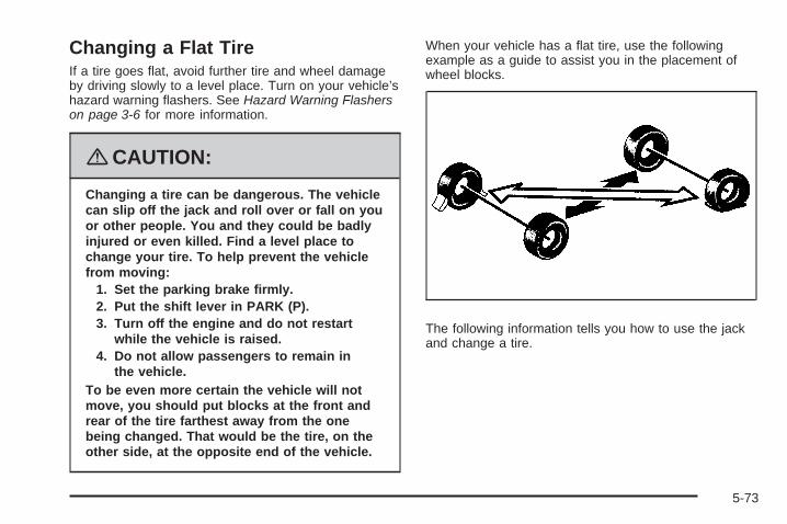
Changing a Flat TireIf a tire goes flat, avoid further tire and wheel damageby driving slowly to a level place. Turn on your vehicle’shazard warning flashers. See Hazard Warning Flasherson page 3-6 for more information.
{CAUTION:
Changing a tire can be dangerous. The vehiclecan slip off the jack and roll over or fall on youor other people. You and they could be badlyinjured or even killed. Find a level place tochange your tire. To help prevent the vehiclefrom moving:
1. Set the parking brake firmly.2. Put the shift lever in PARK (P).3. Turn off the engine and do not restart
while the vehicle is raised.4. Do not allow passengers to remain in
the vehicle.To be even more certain the vehicle will notmove, you should put blocks at the front andrear of the tire farthest away from the onebeing changed. That would be the tire, on theother side, at the opposite end of the vehicle.
When your vehicle has a flat tire, use the followingexample as a guide to assist you in the placement ofwheel blocks.
The following information tells you how to use the jackand change a tire.
5-73

Removing the Spare Tire and Tools
The tools needed to remove the spare tire are locatedin the storage compartment at the rear of the vehicle, onthe passenger’s side.
To remove the tools:1. Open the liftgate. See Liftgate on page 2-22 for
more information.2. Remove the convenience net, if the vehicle has one.3. Open the jack storage compartment by lifting the
tab and pulling the cover off.
A. JackB. StrapC. Bracket
D. Wing NutE. Bag and Tools
4. Remove the jack (A) and jacking tools (E) byloosening and then removing the wing nut (D)and bracket (C).
5-74

5. Separate the plastic pouch from the jack andremove the jacking tools, including the foldingwrench and extension, from the pouch.
The tools you will be using include the jack (A),extension (B), and folding wrench (C).
The compact spare tire is located under the rear of thevehicle. See Compact Spare Tire on page 5-89 formore information about the compact spare.
To remove the compact spare tire:
A. Hoist ShaftB. Hoist AssemblyC. Retainer
D. Compact Spare TireE. Extension (Chisel End)F. Folding Wrench
1. Attach the folding wrench (F) to the extension (E)and insert the chisel end on an angle through thehole in the rear bumper and into the hoist shaft (A).
2. Turn the folding wrench counterclockwise to lowerthe compact spare tire (D) to the ground. Continueto turn the wrench so the compact spare tirecan be pulled out from under the vehicle.
5-75

3. Tilt the retainer at the end of the cable to removethe compact spare tire, so it can be pulled upthrough the wheel opening.The hoist is used to store a full-size or a flat road tireunder the vehicle. See Storing a Flat or Spare Tireand Tools on page 5-86 for more information.
4. Remove the compact spare tire from the cable.If the compact spare tire will not lower, check under thevehicle to see if the tire is hanging loose and thecable end and spring under the wheel plate are missing.If so, the secondary latch system is engaged. SeeSecondary Latch System on page 5-83.To continue changing the flat tire, see Removing theFlat Tire and Installing the Spare Tire on page 5-76.
Removing the Flat Tire andInstalling the Spare TireYour vehicle may have aluminum wheels. If so, you willsee exposed stainless steel wheel nuts. Use thewheel wrench to loosen all of the wheel nuts. Do notremove them yet.
Your vehicle may have steel wheel covers. To removethe wheel covers and wheel nut caps, loosen theplastic nut caps with the wheel wrench in acounterclockwise direction. If needed, finish looseningthem with your fingers. The plastic nut caps will notcome off.
Use the flat end of the wheel wrench and pry along theedge of the cover until it comes off. The edge of thewheel cover could be sharp, so do not try to remove itwith your bare hands. Do not drop the cover or layit face down, as it could become scratched or damaged.
5-76

Store the wheel cover securely in the rear of thevehicle until you have the flat tire repaired or replaced.Once the wheel cover has been removed, use thefollowing procedure to remove the flat tire and installthe spare tire.
1. Do a safety check is done before proceeding.See Changing a Flat Tire on page 5-73 for moreinformation.
2. Loosen the wheel nutsusing the foldingwrench, but do notremove them.
Turn the handle counterclockwise about180 degrees, then flip the handle back to thestarting position. This avoids taking the wrench offthe lug nut for each turn.
5-77

A. Front LocationB. Rear Location
Notice: If your vehicle has wheel locks and animpact wrench is used to remove the wheel nuts,the lock nut or wheel lock key could be damaged.Do not use an impact wrench to remove thewheel nuts if your vehicle has wheel locks.
Notice: If a jack is used to raise the vehicle withoutpositioning it correctly, your vehicle could bedamaged. When raising your vehicle on a jack,avoid contact with the rear axle control arms.
Notice: If you position the jack under the rockermolding and attempt to raise the vehicle, you couldbreak the molding and/or cause other damage toyour vehicle. Always position the jack so that whenthe jack head is raised, it will fit firmly in thenotch located inboard from the rocker molding.
3. Near each wheel, there is a notch (A and B) in thevehicle’s frame, inboard of the rocker molding.Position the jack and raise the jack head until it fitsfirmly into the notch in the vehicle’s frame nearestthe flat tire.Do not raise the vehicle yet.
4. Put the compact spare tire near you.
5-78

{CAUTION:
Getting under a vehicle when it is jacked upis dangerous. If the vehicle slips off the jack,you could be badly injured or killed. Never getunder a vehicle when it is supported only bya jack.
{CAUTION:
Raising your vehicle with the jack improperlypositioned can damage the vehicle and evenmake the vehicle fall. To help avoid personalinjury and vehicle damage, be sure to fit thejack lift head into the proper location beforeraising the vehicle.
5. Attach the folding wrench (A) to the jack (B), andturn the wrench clockwise to raise the jack headapproximately 3 inches (7.6 cm).
5-79

6. Raise the vehicle by turning the folding wrenchclockwise in the jack. Raise the vehicle far enoughoff the ground so there is enough room for thecompact spare tire to fit under the wheel well.
7. Remove all the wheel nuts and take off the flat tire.
{CAUTION:
Rust or dirt on a wheel, or on the parts towhich it is fastened, can make wheel nutsbecome loose after time. The wheel couldcome off and cause an accident. When youchange a wheel, remove any rust or dirt fromplaces where the wheel attaches to the vehicle.In an emergency, you can use a cloth or apaper towel to do this; but be sure to use ascraper or wire brush later, if needed, to get allthe rust or dirt off. See Changing a Flat Tireon page 5-73.
5-80

{CAUTION:
Never use oil or grease on studs or nuts.Because the nuts might come loose. Thevehicle’s wheel could fall off, causing a crash.
8. Remove any rust or dirtfrom the wheel bolts,mounting surfacesand spare wheel.
9. Install the compactspare tire and put thewheel nuts backon with the roundedend of the nuts towardthe wheel.
Tighten each nut by hand until the wheel is heldagainst the hub.
5-81

10. Lower the vehicle by attaching the folding wheelwrench to the jack and turning the wrenchcounterclockwise. Lower the jack completely.
{CAUTION:
Incorrect or improperly tightened wheel nutscan cause the wheel to come loose andeven come off. This could lead to a crash.If you have to replace them, be sure to getnew original equipment wheel nuts.Stop somewhere as soon as you can and havethe nuts tightened with a torque wrench to theproper torque specification. See Capacitiesand Specifications on page 5-105 for wheel nuttorque specification.
Notice: Improperly tightened wheel nuts can leadto brake pulsation and rotor damage. To avoidexpensive brake repairs, evenly tighten the wheelnuts in the proper sequence and to the propertorque specification. See Capacities andSpecifications on page 5-105 for the wheel nuttorque specification.
5-82

11. Tighten the wheel nutsfirmly in a crisscrosssequence, as shown.
Notice: Wheel covers will not fit on your vehicle’scompact spare. If you try to put a wheel coveron the compact spare, the cover or the spare couldbe damaged.
Secondary Latch SystemYour vehicle may have an underbody-mounted tire hoistassembly equipped with a secondary latch system.It is designed to stop a tire from suddenly falling off yourvehicle if the cable holding the spare tire is damaged.For the secondary latch to work, the tire must be stowedwith the valve stem pointing down.
Your vehicle uses the underbody tire hoist assembly tostore either the compact spare or a flat road tire.See Storing a Flat or Spare Tire and Tools on page 5-86for instructions on storing the spare or flat tire correctly.
{CAUTION:
Before beginning this procedure read all theinstructions. Failure to read and follow theinstructions could damage the hoist assemblyand you and others could get hurt. Read andfollow the instructions listed next.
5-83

{CAUTION:
Someone standing too close during theprocedure could be injured by the jack.If the spare tire does not slide off the jackcompletely, make sure no one is behind you oron either side of you as you pull the jack outfrom the under spare.
To release the spare tire from the secondary latch:
1. Place the jack under the vehicle, ahead of the rearbumper. Position the center lift point of the jackunder the center of the compact spare tire.
5-84

2. Turn the folding wrench clockwise to raise the jackuntil it lifts the secondary latch device under thewheel plate.
3. Keep raising the jack until the compact spare tirestops moving upward and is held firmly in place.This lets you know that the secondary latchhas released.
4. Lower the jack by turning the folding wrenchcounterclockwise. Keep lowering the jack untilthe compact spare tire is resting on the foldingwrench.
5. Grasp the compact spare tire with both hands andpull it out from under the vehicle.
6. Reach under the vehicle and remove the foldingwrench and jack.
Have the hoist assembly inspected as soon as you can.You will not be able to store a spare or flat tire usingthe hoist assembly until it has been repaired or replaced.
5-85

Storing a Flat or Spare Tireand Tools
{CAUTION:
Storing a jack, a tire, or other equipment in thepassenger compartment of the vehicle couldcause injury. In a sudden stop or collision,loose equipment could strike someone.Store all these in the proper place.
Storing the Flat or Spare Tire
{CAUTION:
The underbody-mounted spare tire needs tobe stored with the valve stem pointing down.If the spare tire is stored with the valve stempointing upwards, its secondary latch will notwork properly and the spare tire could loosenand suddenly fall from your vehicle. If thishappened when your vehicle was being driven,the tire might contact a person or anothervehicle, causing injury and, of course,damage to itself as well. Be sure theunderbody-mounted spare tire is storedwith its valve stem pointing down.
5-86

To store the spare tire:
1. Lay the tire near the rear of the vehicle with thevalve stem down.
2. Remove the small center cap by tapping the backof the cap with the extension of the shaft, if thevehicle has aluminum wheels.
3. Slide the cable retainer through the center of thewheel and start to raise the tire.Make sure the retainer is fully seated across theunderside of the wheel.
4. When the tire is almost in the stored position, turnthe tire so the valve is towards the rear of thevehicle.This will help when you check and maintain tirepressure in the spare.
5. Raise the tire fully against the underside of thevehicle. Continue turning the folding wrench untilyou feel more than two clicks. This indicates that thecompact spare tire is secure and the cable istight. The spare tire hoist cannot be overtightened.
6. Make sure the tire is stored securely. Push, pull (A),and then try to turn (B) the tire. If the tire moves,use the folding wrench to tighten the cable.
5-87

Storing the Tools
A. StrapB. Bag and ToolsC. Jack
Put back all tools as they were stored in the jackstorage compartment and put the compartment coverback on.
To replace the cover, line up the tabs on the right of thecover with the slots in the cover opening. Push thecover in place and push down the tab so that it rests inthe groove. This secures the cover in place.
Store the center cap or the plastic bolt-on wheel coversuntil a full size tire is put back on the vehicle.When you replace the compact spare with a full-sizetire, reinstall the bolt-on wheel covers or the center cap.Hand-tighten them over the wheel nuts, using thefolding wrench.
5-88

Compact Spare TireAlthough the compact spare tire was fully inflated whenthe vehicle was new, it can lose air after a time.Check the inflation pressure regularly. It should be60 psi (420 kPa).
After installing the compact spare on the vehicle, stopas soon as possible and make sure the spare tireis correctly inflated. The compact spare is made toperform well at speeds up to 65 mph (105 km/h)for distances up to 3,000 miles (5 000 km), so you canfinish your trip and have the full-size tire repaired orreplaced at your convenience. Of course, it is bestto replace the spare with a full-size tire as soon aspossible. The spare tire will last longer and be in goodshape in case it is needed again.
Notice: When the compact spare is installed,do not take your vehicle through an automaticcar wash with guide rails. The compact spare canget caught on the rails. That can damage the tire andwheel, and maybe other parts of your vehicle.
Do not use the compact spare on other vehicles.
And do not mix the compact spare tire or wheel withother wheels or tires. They will not fit. Keep thespare tire and its wheel together.
Notice: Tire chains will not fit your compact spare.Using them can damage your vehicle and candamage the chains too. Do not use tire chains onyour compact spare.
5-89
Appearance Care
Interior CleaningYour vehicle’s interior will continue to look its best if it iscleaned often. Although not always visible, dust anddirt can accumulate on your upholstery. Dirt can damagecarpet, fabric, leather, and plastic surfaces. Regularvacuuming is recommended to remove particlesfrom your upholstery. It is important to keep yourupholstery from becoming and remaining heavily soiled.Soils should be removed as quickly as possible.Your vehicle’s interior may experience extremes of heatthat could cause stains to set rapidly.
Lighter colored interiors may require more frequentcleaning. Use care because newspapers and garmentsthat transfer color to your home furnishings may alsotransfer color to your vehicle’s interior.
When cleaning your vehicle’s interior, only use cleanersspecifically designed for the surfaces being cleaned.Permanent damage may result from using cleaners onsurfaces for which they were not intended. Use glasscleaner only on glass. Remove any accidentalover-spray from other surfaces immediately. To preventover-spray, apply cleaner directly to the cleaningcloth.
Notice: If you use abrasive cleaners when cleaningglass surfaces on your vehicle, you could scratchthe glass and/or cause damage to the rear windowdefogger. When cleaning the glass on yourvehicle, use only a soft cloth and glass cleaner.
Many cleaners contain solvents that may becomeconcentrated in your vehicle’s breathing space.Before using cleaners, read and adhere to all safetyinstructions on the label. While cleaning your vehicle’sinterior, maintain adequate ventilation by openingyour vehicle’s doors and windows.
Dust may be removed from small buttons and knobsusing a small brush with soft bristles.
Your dealer/retailer has a product for cleaning yourvehicle’s glass. Should it become necessary, you canalso obtain a product from your dealer/retailer to removeodors from your vehicle’s upholstery.
Do not clean your vehicle using the following cleanersor techniques:• Never use a knife or any other sharp object to
remove a soil from any interior surface.• Never use a stiff brush. It can cause damage to
your vehicle’s interior surfaces.• Never apply heavy pressure or rub aggressively
with a cleaning cloth. Use of heavy pressurecan damage your interior and does not improve theeffectiveness of soil removal.
5-90

• Use only mild, neutral-pH soaps. Avoid laundrydetergents or dishwashing soaps with degreasers.Using too much soap will leave a residue thatleaves streaks and attracts dirt. For liquid cleaners,about 20 drops per gallon (3.78 L) of water is agood guide.
• Do not heavily saturate your upholstery whilecleaning.
• Damage to your vehicle’s interior may result fromthe use of many organic solvents such as naptha,alcohol, etc.
Fabric/CarpetUse a vacuum cleaner with a soft brush attachmentfrequently to remove dust and loose dirt. A canistervacuum with a beater bar in the nozzle may onlybe used on floor carpet and carpeted floor mats.For soils, always try to remove them first with plainwater or club soda. Before cleaning, gently remove asmuch of the soil as possible using one of the followingtechniques:• For liquids: gently blot the remaining soil with a
paper towel. Allow the soil to absorb into thepaper towel until no more can be removed.
• For solid dry soils: remove as much as possibleand then vacuum.
To clean, use the following instructions:
1. Saturate a lint-free, clean white cloth with water orclub soda.
2. Wring the cloth to remove excess moisture.
3. Start on the outside edge of the soil and gently rubtoward the center. Continue cleaning, using a cleanarea of the cloth each time it becomes soiled.
4. Continue to gently rub the soiled area until thecleaning cloth remains clean.
5. If the soil is not completely removed, use a mildsoap solution and repeat the cleaning processthat was used with plain water.
If any of the soil remains, a commercial fabric cleaner orspot lifter may be necessary. When a commercialupholstery cleaner or spot lifter is to be used, test asmall hidden area for colorfastness first. If the locallycleaned area gives any impression that a ring formationmay result, clean the entire surface.
After the cleaning process has been completed, a papertowel can be used to blot excess moisture from thefabric or carpet.
5-91
LeatherA soft cloth dampened with water can be used toremove dust. If a more thorough cleaning is necessary,a soft cloth dampened with a mild soap solution canbe used. Allow the leather to dry naturally. Do notuse heat to dry. Never use steam to clean leather.Never use spot lifters or spot removers on leather.Many commercial leather cleaners and coatings that aresold to preserve and protect leather may permanentlychange the appearance and feel of your leather and arenot recommended. Do not use silicone or wax-basedproducts, or those containing organic solvents to cleanyour vehicle’s interior because they can alter theappearance by increasing the gloss in a non-uniformmanner. Never use shoe polish on leather.
Instrument Panel, Vinyl, and OtherPlastic SurfacesA soft cloth dampened with water may be used toremove dust. If a more thorough cleaning is necessary,a clean soft cloth dampened with a mild soap solutioncan be used to gently remove dust and dirt.
Never use spot lifters or removers on plastic surfaces.Many commercial cleaners and coatings that are soldto preserve and protect soft plastic surfaces maypermanently change the appearance and feel of yourinterior and are not recommended. Do not use siliconeor wax-based products, or those containing organicsolvents to clean your vehicle’s interior becausethey can alter the appearance by increasing the gloss ina non-uniform manner.
Some commercial products may increase gloss on yourinstrument panel. The increase in gloss may causeannoying reflections in the windshield and even make itdifficult to see through the windshield under certainconditions.
Child Restraint PadThe built-in child restraint pad is attached to the seatframe with fastener strips. You can remove the pad andhand wash it with mild soap and water.
5-92

Care of Safety Belts and Built-inChild Restraint HarnessKeep the safety belts and the built-in child restraintharness clean and dry.
{CAUTION:
Do not bleach or dye safety belts or the built-inchild restraint harness. If you do, they may beseverely weakened. In a crash, they might notbe able to provide adequate protection. Cleanthe safety belts and the child restraint harnessonly with mild soap and lukewarm water.
WeatherstripsSilicone grease on weatherstrips will make them lastlonger, seal better, and not stick or squeak. Applysilicone grease with a clean cloth. During very cold,damp weather frequent application may be required.See Recommended Fluids and Lubricants on page 6-11.
Washing Your VehicleThe best way to preserve your vehicle’s finish is to keepit clean by washing it often.
Notice: Certain cleaners contain chemicals that candamage the emblems or nameplates on your vehicle.Check the cleaning product label. If it states thatis should not be used on plastic parts, do not use iton your vehicle or damage may occur and itwould not be covered by the warranty.
Do not wash the vehicle in direct sunlight. Use a carwashing soap. Do not use cleaning agents thatare petroleum based or that contain acid or abrasives,as they can damage the paint, metal or plastic onyour vehicle. Approved cleaning products can beobtained from your dealer/retailer. See VehicleCare/Appearance Materials on page 5-97. Follow allmanufacturers’ directions regarding correct productusage, necessary safety precautions and appropriatedisposal of any vehicle care product.
Rinse the vehicle well, before washing and after toremove all cleaning agents completely. If they areallowed to dry on the surface, they could stain.
Dry the finish with a soft, clean chamois or an all-cottontowel to avoid surface scratches and water spotting.
5-93

High pressure car washes may cause water to enter thevehicle. Avoid using high pressure washes closerthan 12 inches (30 cm) to the surface of the vehicle.Use of power washers exceeding 1,200 psi (8 274 kPa)can result in damage or removal of paint and decals.
Cleaning Exterior Lamps/LensesUse only lukewarm or cold water, a soft cloth and acar washing soap to clean exterior lamps and lenses.Follow instructions under Washing Your Vehicle onpage 5-93.
Finish CareOccasional waxing or mild polishing of your vehicle byhand may be necessary to remove residue from thepaint finish. You can get approved cleaning productsfrom your dealer/retailer. See Vehicle Care/AppearanceMaterials on page 5-97.
If your vehicle has a basecoat/clearcoat paint finish,the clearcoat gives more depth and gloss to the coloredbasecoat. Always use waxes and polishes that arenon-abrasive and made for a basecoat/clearcoatpaint finish.
Notice: Machine compounding or aggressivepolishing on a basecoat/clearcoat paint finish maydamage it. Use only non-abrasive waxes andpolishes that are made for a basecoat/clearcoatpaint finish on your vehicle.
Foreign materials such as calcium chloride and othersalts, ice melting agents, road oil and tar, tree sap, birddroppings, chemicals from industrial chimneys, etc., candamage your vehicle’s finish if they remain on paintedsurfaces. Wash the vehicle as soon as possible.If necessary, use non-abrasive cleaners that are markedsafe for painted surfaces to remove foreign matter.
Exterior painted surfaces are subject to aging, weatherand chemical fallout that can take their toll over aperiod of years. You can help to keep the paint finishlooking new by keeping your vehicle garaged or coveredwhenever possible.
Protecting Exterior Bright Metal PartsBright metal parts should be cleaned regularly to keeptheir luster. Washing with water is all that is usuallyneeded. However, you may use chrome polish onchrome or stainless steel trim, if necessary.
Use special care with aluminum trim. To avoid damagingprotective trim, never use auto or chrome polish,steam or caustic soap to clean aluminum. A coating ofwax, rubbed to high polish, is recommended for allbright metal parts.
5-94

Windshield, Backglass, andWiper BladesClean the outside of the windshield and backglass withglass cleaner.
Clean the rubber blades using a lint free cloth or papertowel soaked with windshield washer fluid or a milddetergent. Wash the windshield thoroughly when youclean the blades. Bugs, road grime, sap and a buildup ofvehicle wash/wax treatments may cause wiperstreaking. Replace the wiper blades if they are worn ordamaged.
Wipers can be damaged by:• Extreme dusty conditions• Sand and salt• Heat and sun• Snow and ice, without proper removal
Aluminum WheelsNotice: If you use strong soaps, chemicals,abrasive polishes, cleaners, brushes, or cleanersthat contain acid on aluminum or chrome-platedwheels, you could damage the surface of thewheel(s). The repairs would not be covered by yourwarranty. Use only approved cleaners on aluminumor chrome-plated wheels.
Keep the wheels clean using a soft clean cloth with mildsoap and water. Rinse with clean water. After rinsingthoroughly, dry with a soft clean towel. A wax may thenbe applied.
Notice: Using chrome polish on aluminum wheelscould damage the wheels. The repairs would notbe covered by your warranty. Use chrome polish onchrome wheels only.
The surface of these wheels is similar to the paintedsurface of the vehicle. Do not use strong soaps,chemicals, abrasive polishes, abrasive cleaners,cleaners with acid, or abrasive cleaning brushes onthem because the surface could be damaged. Do notuse chrome polish on aluminum wheels.
Notice: If you drive your vehicle through anautomatic car wash that has silicone carbide tirecleaning brushes, you could damage the aluminumor chrome-plated wheels. The repairs would notbe covered by your warranty. Never drive a vehicleequipped with aluminum or chrome-plated wheelsthrough an automatic car wash that uses siliconecarbide tire cleaning brushes.
5-95

TiresTo clean the tires, use a stiff brush with tire cleaner.
Notice: Using petroleum-based tire dressingproducts on your vehicle may damage the paintfinish and/or tires. When applying a tire dressing,always wipe off any overspray from all paintedsurfaces on your vehicle.
Sheet Metal DamageIf the vehicle is damaged and requires sheet metalrepair or replacement, make sure the body repair shopapplies anti-corrosion material to parts repaired orreplaced to restore corrosion protection.
Original manufacturer replacement parts will provide thecorrosion protection while maintaining the warranty.
Finish DamageAny stone chips, fractures or deep scratches in the finishshould be repaired right away. Bare metal will corrodequickly and may develop into major repair expense.
Minor chips and scratches can be repaired withtouch-up materials available from your dealer/retailer.Larger areas of finish damage can be corrected in yourdealer’s/retailer’s body and paint shop.
Underbody MaintenanceChemicals used for ice and snow removal and dustcontrol can collect on the underbody. If these are notremoved, corrosion and rust can develop on theunderbody parts such as fuel lines, frame, floor pan,and exhaust system even though they have corrosionprotection.
At least every spring, flush these materials from theunderbody with plain water. Clean any areas where mudand debris can collect. Dirt packed in close areas ofthe frame should be loosened before being flushed.Your dealer/retailer or an underbody car washing systemcan do this for you.
Chemical Paint SpottingSome weather and atmospheric conditions can create achemical fallout. Airborne pollutants can fall upon andattack painted surfaces on the vehicle. This damage cantake two forms: blotchy, ring-shaped discolorations, andsmall, irregular dark spots etched into the paint surface.
Although no defect in the paint job causes this, we willrepair, at no charge to the owner, the surfaces ofnew vehicles damaged by this fallout condition within12 months or 12,000 miles (20 000 km) of purchase,whichever occurs first.
5-96

Vehicle Care/Appearance Materials
Description Usage
Polishing Cloth Interior and exteriorpolishing cloth.
Tar and RoadOil Remover
Removes tar, road oil,and asphalt.
Chrome Cleanerand Polish
Use on chrome orstainless steel.
White SidewallTire Cleaner
Removes soil and blackmarks from whitewallsand raised white lettering.
Vinyl Cleaner Cleans vinyl.
Glass Cleaner Removes dirt, grime,smoke and fingerprints.
Chrome Wheel Cleaner Removes dirt and grimefrom chrome wheels.
Finish Enhancer
Removes dust,fingerprints, and surfacecontaminants. Spray onand wipe off.
Description Usage
Swirl Remover PolishRemoves swirl marks, finescratches, and other lightsurface contamination.
Cleaner Wax Removes light scratchesand protects finish.
Foaming Tire ShineLow Gloss
Cleans, shines, andprotects tires. No wipingnecessary.
Wash Wax Concentrate
Medium foamingshampoo. Cleans andlightly waxes.Biodegradable andphosphate free.
Spot Lifter
Quickly removes spotsand stains from carpets,vinyl, and clothupholstery.
Odor EliminatorOdorless spray odoreliminator used on fabrics,vinyl, leather and carpet.
5-97

Vehicle Identification
Vehicle Identification Number (VIN)
This is the legal identifier for your vehicle. It appearson a plate in the front corner of the instrument panel,on the driver side. You can see it if you look through thewindshield from outside your vehicle. The VIN alsoappears on the Certification/Tire and Service Partslabels and the certificates of title and registration.
Engine IdentificationThe eighth character in the VIN is the engine code.This code helps you identify your vehicle’s engine,specifications, and replacement parts.
Service Parts Identification LabelThis label is on the inside of the glove box. It is veryhelpful if you ever need to order parts. The label has thefollowing information:
• Vehicle Identification Number (VIN)
• Model designation
• Paint information
• Production options and special equipment
Do not remove this label from the vehicle.
5-98

Electrical System
Add-On Electrical EquipmentNotice: Do not add anything electrical to yourvehicle unless you check with your dealer/retailerfirst. Some electrical equipment can damageyour vehicle and the damage would not be coveredby your warranty. Some add-on electrical equipmentcan keep other components from working as theyshould.
Add-on equipment can drain your vehicle’s battery, evenif your vehicle is not operating.
Your vehicle has an airbag system. Before attempting toadd anything electrical to your vehicle, see ServicingYour Airbag-Equipped Vehicle on page 1-90.
Headlamp WiringThe headlamp wiring is protected by four internal fusesin the underhood fuse block. An electrical overloadwill cause the lamps to go on and off, or in some casesto remain off. If this happens, have your headlampwiring checked right away.
Windshield Wiper FusesThe windshield wiper motor is protected by an internalfuse in the underhood fuse block. If the motor overheatsdue to heavy snow, etc., the wiper will stop until themotor cools. If the overload is caused by some electricalproblem, be sure to get it fixed.
The rear washer pump is controlled by a relay locatedin the engine compartment, behind the windshieldwasher fluid reservoir. The rear wiper motor is protectedby a fuse located in the instrument panel fuse block.
Power Windows and OtherPower OptionsCircuit breakers in the instrument panel fuse panelprotect the power windows and other power accessories.When the current load is too heavy, the circuit breakeropens and closes, protecting the circuit until theproblem is fixed.
5-99

Fuses and Circuit BreakersThe wiring circuits in your vehicle are protected fromshort circuits by a combination of fuses, circuit breakersand fusible thermal links. This greatly reduces thechance of fires caused by electrical problems.
Look at the silver-colored band inside the fuse. If theband is broken or melted, replace the fuse. Be sure youreplace a bad fuse with a new one of the identicalsize and rating.
If you ever have a problem on the road and don’t havea spare fuse, you can borrow one that has the sameamperage. Just pick some feature of your vehiclethat you can get along without – like the radio orcigarette lighter – and use its fuse, if it is the correctamperage. Replace it as soon as you can.
Instrument Panel Fuse BlockThe instrument panel fuse block is located at the rightend of the instrument panel, on the passenger sideof the vehicle. Open the front passenger’s door,and remove the cover, to access the fuse block.
Your vehicle may not have all of the fuses listed.
5-100

Fuses Usage
1 Trunk, Door Locks
2 Electronic Level Control
3 Rear Wiper
4 Radio, DVD Player
5 Interior Lamps
6 OnStar®
7 Keyless Entry Module
8 Cluster, Heating, Ventilation,Air Conditioning
9 Cruise Switch
10 Steering Wheel Illumination
11 Power Mirror
12 Stoplamp, Turn Lamps
13 Heated Seats
14 Blank
15 Electronic Level Control
16 Heated Mirror
17 Center High-Mounted Stoplamp,Back-up Lamps
18 Blank
Fuses Usage
19 Canister Vent Solenoid
20 Park Lamps
21 Power Sliding Door
22 Blank
23 Blank
24 Left Power Sliding Door
25 Right Power Sliding Door
Relays Usage
26 Blank
27 Blank
28 Park Lamps, Taillamps
29 Retained Accessory Power
30 Rear Defog
PLR Fuse Puller
CircuitBreakers
Usage
31 Power Seats
32 Power Window
5-101

Underhood Fuse BlockThe underhood fuse block is located in the engine compartment. For more information on location see EngineCompartment Overview on page 5-12.
Notice: Spilling liquid on any electrical components on your vehicle may damage it. Always keep the coverson any electrical component.
Your vehicle may not have all the fuses listed.
5-102

Fuses Usage
1 Right High-Beam
2 Fuel Pump
3 Diode
BLANK Not Used
BLANK Not Used
4 Left High-Beam
BLANK Not Used
BLANK Not Used
BLANK Not Used
5 Not Used
6 Air Conditioning Clutch
7 Horn
8 Left Low-Beam
9 Powertrain Control Module,Electronic Throttle Control
10 Not Used
11 Transmission Solenoid
12 Right Low-Beam
Fuses Usage
13 Antilock Brake System
14 Powertrain Control Module Ignition
15 Electronic Ignition
16 Fuel Injector
17 Climate Control, RPA, CruiseControl
18 Electronic Throttle Control
19 Engine Sensor, Evaporator
20 Airbag
21 Not Used
22 Not Used
23 Auxiliary Power
24 Front Windshield Washer
25 AC/DC Inverter
26 Rear Blower
27 Front Blower
28 Front Windshield Wiper
5-103
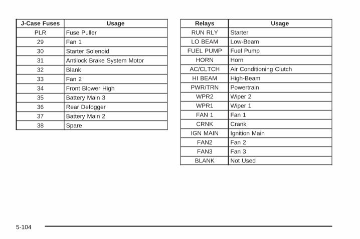
J-Case Fuses Usage
PLR Fuse Puller
29 Fan 1
30 Starter Solenoid
31 Antilock Brake System Motor
32 Blank
33 Fan 2
34 Front Blower High
35 Battery Main 3
36 Rear Defogger
37 Battery Main 2
38 Spare
Relays Usage
RUN RLY Starter
LO BEAM Low-Beam
FUEL PUMP Fuel Pump
HORN Horn
AC/CLTCH Air Conditioning Clutch
HI BEAM High-Beam
PWR/TRN Powertrain
WPR2 Wiper 2
WPR1 Wiper 1
FAN 1 Fan 1
CRNK Crank
IGN MAIN Ignition Main
FAN2 Fan 2
FAN3 Fan 3
BLANK Not Used
5-104

Capacities and SpecificationsThe following approximate capacities are given in English and metric measurements. See Recommended Fluids andLubricants on page 6-11 for more information.
ApplicationCapacities
English Metric
Air Conditioning Refrigerant R134aFor the air conditioning system refrigerant charge
amount, see the refrigerant caution label located underthe hood. See your dealer/retailer for more information.
Automatic Transaxle — Pan Removal and Replacement 7.4 qt 7.0 L
Cooling System
3.9L Engine Front Climate Controls Only 10.77 qt 10.2 L
3.9L Engine with Rear Climate Controls 12.11 qt 11.55 L
Engine Oil with Filter 4.0 qt 3.8 L
Fuel Capacity
Regular 20.0 gal 75.7 L
Extended 25.1 gal 95.0 L
Wheel Nut Torque 100 ft lb 140 YAll capacities are approximate. When adding, be sure to fill to the approximate level, as recommended in thismanual. Recheck fluid level after filling.
Engine VIN Code Transaxle Spark Plug Gap
3.9L V6 Flexible Fuel W Automatic 0.040 inches (1.1 mm)
3.9L V6 1 Automatic 0.040 inches (1.1 mm)
5-105

✍ NOTES
5-106

Maintenance Schedule ......................................6-2Introduction ...................................................6-2Maintenance Requirements ..............................6-2Your Vehicle and the Environment ....................6-2Using the Maintenance Schedule ......................6-2Scheduled Maintenance ...................................6-4Additional Required Services ............................6-6Maintenance Footnotes ...................................6-7
Owner Checks and Services ............................6-8At Each Fuel Fill ............................................6-8At Least Once a Month ...................................6-9At Least Once a Year .....................................6-9Recommended Fluids and Lubricants ...............6-11Normal Maintenance Replacement Parts ..........6-13Engine Drive Belt Routing ..............................6-14Maintenance Record .....................................6-15
Section 6 Maintenance Schedule
6-1

Maintenance Schedule
IntroductionImportant: Keep engine oil at the proper level andchange as recommended.
Have you purchased the GM Protection Plan? The Plansupplements your new vehicle warranties. See yourWarranty and Owner Assistance booklet or yourdealer/retailer for details.
Maintenance RequirementsNotice: Maintenance intervals, checks, inspections,replacement parts, and recommended fluids andlubricants as prescribed in this manual are necessaryto keep your vehicle in good working condition.Any damage caused by failure to follow scheduledmaintenance might not be covered by warranty.
Your Vehicle and the EnvironmentProper vehicle maintenance not only helps to keepyour vehicle in good working condition, but also helpsthe environment. All recommended maintenance isimportant. Improper vehicle maintenance can evenaffect the quality of the air we breathe. Improper fluidlevels or the wrong tire inflation can increase the levelof emissions from your vehicle. To help protect ourenvironment, and to keep your vehicle in good condition,be sure to maintain your vehicle properly.
Using the Maintenance ScheduleWe want to help you keep your vehicle in good workingcondition. But we do not know exactly how you willdrive it. You might drive very short distances only afew times a week. Or you might drive long distancesall the time in very hot, dusty weather. You mightuse your vehicle in making deliveries. Or you mightdrive it to work, to do errands, or in many other ways.
Because of all the different ways people use theirvehicles, maintenance needs vary. You might need morefrequent checks and replacements. So please readthe following and note how you drive. If you have anyquestions on how to keep your vehicle in good condition,see your dealer/retailer.
6-2
This schedule is for vehicles that:• carry passengers and cargo within recommended
limits. You will find these limits on the Tire andLoading Information label. See Loading YourVehicle on page 4-21.
• are driven on reasonable road surfaces withinlegal driving limits.
• use the recommended fuel. See Gasoline Octaneon page 5-5.
The services in Scheduled Maintenance on page 6-4should be performed when indicated. See AdditionalRequired Services on page 6-6 and MaintenanceFootnotes on page 6-7 for further information.
{CAUTION:
Performing maintenance work on a vehiclecan be dangerous. In trying to do some jobs,you can be seriously injured. Do your ownmaintenance work only if you have therequired know-how and the proper tools andequipment for the job. If you have any doubt,see your dealer/retailer to have a qualifiedtechnician do the work. See Doing Your OwnService Work on page 5-4.
Some maintenance services can be complex.So, unless you are technically qualified and havethe necessary equipment, you should have yourdealer/retailer do these jobs.
When you go to your dealer/retailer for your serviceneeds, you will know that trained and supported servicetechnicians will perform the work using genuine parts.
If you want to purchase service information, see ServicePublications Ordering Information on page 7-15.
Owner Checks and Services on page 6-8 tells youwhat should be checked, when to check it, and whatyou can easily do to help keep your vehicle in goodcondition.
The proper replacement parts, fluids, and lubricants touse are listed in Recommended Fluids and Lubricantson page 6-11 and Normal Maintenance ReplacementParts on page 6-13. When your vehicle is serviced,make sure these are used. All parts should be replacedand all necessary repairs done before you or anyoneelse drives the vehicle. We recommend the use ofgenuine parts from your dealer/retailer.
6-3

Scheduled MaintenanceWhen the CHANGE OIL SOON message comes on,it means that service is required for your vehicle. Haveyour vehicle serviced as soon as possible within thenext 600 miles (1 000 km). It is possible that, if youare driving under the best conditions, the engine oillife system may not indicate that vehicle serviceis necessary for over a year. However, your engineoil and filter must be changed at least once a yearand at this time the system must be reset. Yourdealer/retailer has trained service technicians whowill perform this work using genuine parts and resetthe system.
If the engine oil life system is ever reset accidentally,you must service your vehicle within 3,000 miles(5 000 km) since your last service. Remember to resetthe oil life system whenever the oil is changed. SeeEngine Oil Life System on page 5-16 for information onthe Engine Oil Life System and resetting the system.
When the CHANGE OIL SOON message appears,certain services, checks, and inspections are required.Required services are described in the following for“Maintenance I” and “Maintenance II.” Generally, it isrecommended that your first service be Maintenance I,your second service be Maintenance II, and that youalternate Maintenance I and Maintenance II thereafter.However, in some cases, Maintenance II may berequired more often.
Maintenance I — Use Maintenance I if the CHANGEOIL SOON message comes on within 10 monthssince the vehicle was purchased or Maintenance IIwas performed.
Maintenance II — Use Maintenance II if the previousservice performed was Maintenance I. Always useMaintenance II whenever the message comes on10 months or more since the last service or if themessage has not come on at all for one year.
6-4

Scheduled MaintenanceService Maintenance I Maintenance II
Change engine oil and filter. See Engine Oil on page 5-13. Reset oil life system.See Engine Oil Life System on page 5-16. An Emission Control Service. • •
Lubricate chassis components. See footnote #. • •Visually check for any leaks or damage. See footnote (k). • •Inspect engine air cleaner filter. If necessary, replace filter. See Engine AirCleaner/Filter on page 5-18. See footnote (g). •
Rotate tires and check inflation pressures and wear. See Tire Inspection andRotation on page 5-62 and “Tire Wear Inspection” in At Least Once a Monthon page 6-9.
• •
Inspect brake system. See footnote (a). • •Check engine coolant and windshield washer fluid levels and add fluid as needed. • •Perform any needed additional services. See “Additional Required Services”in this section. • •
Inspect suspension and steering components. See footnote (b). •Inspect engine cooling system. See footnote (c). •Inspect wiper blades. See footnote (d). •Inspect restraint system components. See footnote (e). •Lubricate body components. See footnote (f). •Check transmission fluid level and add fluid as needed. •Replace passenger compartment air filter. See footnote (l). •Inspect throttle system. See footnote (j). •
6-5

Additional Required ServicesThe following services should be performed at the first maintenance service (I or II) after the indicated miles (kilometers)shown for each item.
Additional Required Services
Service and Miles (Kilometers) 25,000(40 000)
50,000(80 000)
75,000(120 000)
100,000(160 000)
125,000(200 000)
150,000(240 000)
Inspect fuel system for damage or leaks. • • • • • •Inspect exhaust system for loose ordamaged components. • • • • • •
Replace engine air cleaner filter. SeeEngine Air Cleaner/Filter on page 5-18. • • •
Change automatic transmission fluid andfilter (severe service). See footnote (h). • • •
Change automatic transmission fluidand filter (normal service). •
Replace spark plugs and inspect sparkplug wires. An Emission Control Service. •
Engine cooling system service (or everyfive years, whichever occurs first).An Emission Control Service.See footnote (i).
•
Inspect engine accessory drive belt.An Emission Control Service.See footnote (m).
•
6-6

Maintenance Footnotes# Lubricate the suspension, steering linkage, and theunderbody contact points and linkage.
(a) Visually inspect brake lines and hoses for properhook-up, binding, leaks, cracks, chafing, etc. Inspectdisc brake pads for wear and rotors for surfacecondition. Inspect other brake parts, including calipers,parking brake, etc. Check parking brake adjustment.
(b) Visually inspect front and rear suspension andsteering system for damaged, loose, or missing parts,signs of wear, or lack of lubrication. Inspect powersteering lines and hoses for proper hook-up, binding,leaks, cracks, chafing, etc.
(c) Visually inspect hoses and have them replaced if theyare cracked, swollen, or deteriorated. Inspect all pipes,fittings and clamps; replace with genuine parts asneeded. To help ensure proper operation, a pressuretest of the cooling system and pressure cap and cleaningthe outside of the radiator and air conditioning condenseris recommended at least once a year.
(d) Inspect wiper blades for wear, cracking, orcontamination. Clean the windshield and wiper blades,if contaminated. Replace wiper blades that are worn
or damaged. See Windshield Wiper Blade Replacementon page 5-47 and Windshield, Backglass, and WiperBlades on page 5-95 for more information.
(e) Make sure the safety belt reminder light and safetybelt assemblies are working properly. If your vehiclehas a built-in child restraint, make sure the harnessstraps, latch plates, buckle, clip, child head restraint, andanchorages are working properly. Look for any otherloose or damaged safety belt system parts. If yousee anything that might keep a safety belt system fromdoing its job, have it repaired. Have any torn orfrayed safety belts replaced. Also see Checking theRestraint Systems on page 1-91.
(f) Lubricate all key lock cylinders, hood latchassemblies, secondary latches, pivots, spring anchorand release pawl, hood and door hinges, rear foldingseats, liftgate hinges, fuel door hinge, power slidingdoor cable, and sliding door track(s). More frequentlubrication may be required when exposed to a corrosiveenvironment. Applying silicone grease on weatherstripswith a clean cloth will make them last longer, sealbetter, and not stick or squeak.
(g) If you drive regularly under dusty conditions, inspectthe filter at each engine oil change.
6-7

(h) Change automatic transmission fluid and filter if thevehicle is mainly driven under one or more of theseconditions:
− In heavy city traffic where the outside temperatureregularly reaches 90°F (32°C) or higher.
− In hilly or mountainous terrain.− When doing frequent trailer towing.− Uses such as found in taxi, police, or delivery
service.
(i) Drain, flush, and refill cooling system. See EngineCoolant on page 5-22 for what to use. Inspect hoses.Clean radiator, condenser, pressure cap, and filler neck.Pressure test the cooling system and pressure cap.
(j) Check system for interference or binding andfor damaged or missing parts. Replace parts as needed.Replace any components that have high effort orexcessive wear. Do not lubricate accelerator or cruisecontrol cables.
(k) A fluid loss in any vehicle system could indicate aproblem. Have the system inspected and repairedand the fluid level checked. Add fluid if needed.
(l) If you drive regularly under dusty conditions, the filtermay require replacement more often.
(m) Visually inspect belt for fraying, excessive cracks,or obvious damage. Replace belt if necessary.
Owner Checks and ServicesThese owner checks and services should be performedat the intervals specified to help ensure the safety,dependability, and emission control performance of yourvehicle. Your dealer/retailer can assist you with thesechecks and services.
Be sure any necessary repairs are completed at once.Whenever any fluids or lubricants are added to yourvehicle, make sure they are the proper ones, as shownin Recommended Fluids and Lubricants on page 6-11.
At Each Fuel FillIt is important to perform these underhood checks ateach fuel fill.
Engine Oil Level Check
Notice: It is important to check the engine oilregularly and keep it at the proper level. Failure tokeep the engine oil at the proper level can causedamage to the engine not covered by your warranty.
Check the engine oil level and add the proper oil ifnecessary. See Engine Oil on page 5-13.
6-8

Engine Coolant Level CheckCheck the engine coolant level and add DEX-COOL®
coolant mixture if necessary. See Engine Coolanton page 5-22.
Windshield Washer Fluid Level CheckCheck the windshield washer fluid level in thewindshield washer fluid reservoir and add theproper fluid if necessary.
At Least Once a Month
Tire Inflation CheckInspect your vehicle’s tires and make sure they areinflated to the correct pressures. Do not forget to checkthe spare tire. See Inflation - Tire Pressure on page 5-54.Check to make sure the spare tire is stored securely.See Changing a Flat Tire on page 5-73.
Tire Wear InspectionTire rotation may be required for high mileage highwaydrivers prior to the Engine Oil Life System servicenotification. Check the tires for wear and, if necessary,rotate the tires. See Tire Inspection and Rotationon page 5-62.
At Least Once a Year
Starter Switch Check
{CAUTION:
When you are doing this inspection, the vehiclecould move suddenly. If the vehicle moves,you or others could be injured.
1. Before you start, be sure you have enough roomaround the vehicle.
2. Firmly apply both the parking brake and the regularbrake. See Parking Brake on page 2-38.Do not use the accelerator pedal, and be ready toturn off the engine immediately if it starts.
3. Try to start the engine in each gear. The vehicleshould start only in PARK (P) or NEUTRAL (N).If the vehicle starts in any other position, contactyour dealer/retailer for service.
6-9

Automatic Transmission Shift LockControl System Check
{CAUTION:
When you are doing this inspection, the vehiclecould move suddenly. If the vehicle moves,you or others could be injured.
1. Before you start, be sure you have enough roomaround the vehicle. It should be parked on a levelsurface.
2. Firmly apply the parking brake. See Parking Brakeon page 2-38.Be ready to apply the regular brake immediatelyif the vehicle begins to move.
3. With the engine off, turn the ignition to ON/RUN,but do not start the engine. Without applying theregular brake, try to move the shift lever outof PARK (P) with normal effort. If the shift levermoves out of PARK (P), contact your dealer/retailerfor service.
Ignition Transmission Lock CheckWhile parked, and with the parking brake set, try to turnthe ignition to LOCK/OFF in each shift lever position.
• The ignition should turn to LOCK/OFF onlywhen the shift lever is in PARK (P).
• The ignition key should come out only inLOCK/OFF.
Contact your dealer/retailer if service is required.
Parking Brake and AutomaticTransmission Park (P) Mechanism Check
{CAUTION:
When you are doing this check, your vehiclecould begin to move. You or others couldbe injured and property could be damaged.Make sure there is room in front of yourvehicle in case it begins to roll. Be ready toapply the regular brake at once should thevehicle begin to move.
6-10

Park on a fairly steep hill, with the vehicle facingdownhill. Keeping your foot on the regular brake,set the parking brake.
• To check the parking brake’s holding ability:With the engine running and the transmissionin NEUTRAL (N), slowly remove foot pressurefrom the regular brake pedal. Do this until thevehicle is held by the parking brake only.
• To check the PARK (P) mechanism’s holdingability: With the engine running, shift to PARK (P).Then release the parking brake followed by theregular brake.
Contact your dealer/retailer if service is required.
Underbody Flushing ServiceAt least every spring, use plain water to flush anycorrosive materials from the underbody. Take careto clean thoroughly any areas where mud and otherdebris can collect.
Recommended Fluids andLubricantsFluids and lubricants identified below by name,part number, or specification can be obtained fromyour dealer/retailer.
Usage Fluid/Lubricant
Engine Oil
Engine oil which meets GMStandard GM6094M and displaysthe American Petroleum InstituteCertified for Gasoline Enginesstarburst symbol. To determine theproper viscosity for your vehicle’sengine, see Engine Oil on page 5-13.
Engine Coolant
50/50 mixture of clean, drinkablewater and use only DEX-COOL®
Coolant. See Engine Coolanton page 5-22.
Hydraulic BrakeSystem
Delco® Supreme 11 Brake Fluid orequivalent DOT-3 brake fluid.
6-11

Usage Fluid/Lubricant
WindshieldWasher Optikleen® Washer Solvent.
Power SteeringSystem
GM Power Steering Fluid(GM Part No. U.S. 89021184,in Canada 89021186).
AutomaticTransmission
DEXRON®-VI AutomaticTransmission Fluid.
Key LockCylinders
Multi-Purpose Lubricant, Superlube(GM Part No. U.S. 12346241,in Canada 10953474).
ChassisLubrication
Chassis Lubricant(GM Part No. U.S. 12377985,in Canada 88901242) or lubricantmeeting requirements of NLGI #2,Category LB or GC-LB.
Hood LatchAssembly,Secondary
Latch, Pivots,Spring
Anchor, andRelease Pawl
Lubriplate Lubricant Aerosol(GM Part No. U.S. 12346293,in Canada 992723) or lubricantmeeting requirements of NLGI #2,Category LB or GC-LB.
Usage Fluid/Lubricant
Hood and DoorHinges, RearFolding Seat,
Fuel DoorHinge, Liftgate
Hinges andPower SlidingDoor Cable
Multi-Purpose Lubricant, Superlube(GM Part No. U.S. 12346241,in Canada 10953474).
Sliding DoorTrack
Lubriplate Lubricant Aerosol(GM Part No. U.S. 12346293,in Canada 992723) or lubricantmeeting requirements of NLGI #2,Category LB or GC-LB.
WeatherstripConditioning
Weatherstrip Lubricant(GM Part No. U.S. 3634770,in Canada 10953518) orDielectric Silicone Grease(GM Part No. U.S. 12345579,in Canada 992887).
6-12

Normal Maintenance Replacement PartsReplacement parts identified below by name, part number, or specification can be obtained from your dealer/retailer.
Part GM Part Number ACDelco® Part Number
Engine Air Cleaner/Filter 10354942 A2939C
Engine Oil Filter 89017342 PF61
Spark Plugs 12591131 41-100
Windshield Wiper Blades
Driver’s Side — 22.0 inches (55.0 cm) 12335833 —
Passenger’s Side — 24.0 inches (60.0 cm) 12335834 —
Rear — 16.0 inches (40.0 cm) 15192147 —
6-13

Engine Drive Belt Routing
3.9L V6 Engine and 3.9L V6 Flexible Fuel
6-14

Maintenance RecordAfter the scheduled services are performed, record the date, odometer reading, who performed the service, and thetype of services performed in the boxes provided. See Maintenance Requirements on page 6-2. Any additionalinformation from Owner Checks and Services on page 6-8 can be added on the following record pages. You shouldretain all maintenance receipts.
Maintenance Record
Date OdometerReading Serviced By Maintenance I or
Maintenance II Services Performed
6-15

Maintenance Record (cont’d)
Date OdometerReading Serviced By Maintenance I or
Maintenance II Services Performed
6-16

Maintenance Record (cont’d)
Date OdometerReading Serviced By Maintenance I or
Maintenance II Services Performed
6-17

Maintenance Record (cont’d)
Date OdometerReading Serviced By Maintenance I or
Maintenance II Services Performed
6-18

Customer Assistance and Information ...............7-2Customer Satisfaction Procedure ......................7-2Online Owner Center ......................................7-4Customer Assistance for
Text Telephone (TTY) Users .........................7-5Customer Assistance Offices ............................7-5GM Mobility Reimbursement Program ................7-6Roadside Assistance Program ..........................7-6Scheduling Service Appointments .....................7-9Courtesy Transportation ...................................7-9Collision Damage Repair ................................7-11
Reporting Safety Defects ................................7-14Reporting Safety Defects to the
United States Government ..........................7-14Reporting Safety Defects to the
Canadian Government ................................7-14Reporting Safety Defects to
General Motors .........................................7-14Service Publications Ordering Information .........7-15
Vehicle Data Recording and Privacy ................7-16Event Data Recorders ...................................7-16OnStar® ......................................................7-17Navigation System ........................................7-17Radio Frequency Identification (RFID) ..............7-17
Section 7 Customer Assistance Information
7-1

Customer Assistance andInformation
Customer Satisfaction ProcedureYour satisfaction and goodwill are important toyour dealer and to Chevrolet. Normally, any concernswith the sales transaction or the operation of yourvehicle will be resolved by your dealer’s sales or servicedepartments. Sometimes, however, despite the bestintentions of all concerned, misunderstandings canoccur. If your concern has not been resolved to yoursatisfaction, the following steps should be taken:
STEP ONE: Discuss your concern with a memberof dealership management. Normally, concerns canbe quickly resolved at that level. If the matter hasalready been reviewed with the sales, service, or partsmanager, contact the owner of the dealership or thegeneral manager.
STEP TWO: If after contacting a member of dealershipmanagement, it appears your concern cannot beresolved by the dealership without further help, in theU.S., contact the Chevrolet Customer Assistance Centerby calling 1-800-222-1020. In Canada, contact GeneralMotors of Canada Customer Communication Centre bycalling 1-800-263-3777 (English) or 1-800-263-7854(French).
We encourage you to call the toll-free number in orderto give your inquiry prompt attention. Please have thefollowing information available to give the CustomerAssistance Representative:
• Vehicle Identification Number (VIN). This is availablefrom the vehicle registration or title, or the plate at thetop left of the instrument panel and visible throughthe windshield.
• Dealership name and location.
• Vehicle delivery date and present mileage(kilometers).
When contacting Chevrolet, please remember that yourconcern will likely be resolved at a dealer’s facility.That is why we suggest you follow Step One first ifyou have a concern.
STEP THREE — U.S. Owners: Both General Motorsand your dealer are committed to making sure you arecompletely satisfied with your new vehicle. However, ifyou continue to remain unsatisfied after following theprocedure outlined in Steps One and Two, you shouldfile with the Better Business Bureau (BBB) Auto LineProgram to enforce your rights.
The BBB Auto Line Program is an out of court programadministered by the Council of Better Business Bureausto settle automotive disputes regarding vehicle repairs orthe interpretation of the New Vehicle Limited Warranty.
7-2

Although you may be required to resort to this informaldispute resolution program prior to filing a court action,use of the program is free of charge and your case willgenerally be heard within 40 days. If you do not agreewith the decision given in your case, you may reject it andproceed with any other venue for relief available to you.
You may contact the BBB Auto Line Program using thetoll-free telephone number or write them at the followingaddress:
BBB Auto Line ProgramCouncil of Better Business Bureaus, Inc.4200 Wilson BoulevardSuite 800Arlington, VA 22203-1838
Telephone: 1-800-955-5100
This program is available in all 50 states and theDistrict of Columbia. Eligibility is limited by vehicle age,mileage, and other factors. General Motors reservesthe right to change eligibility limitations and/ordiscontinue its participation in this program.
STEP THREE — Canadian Owners: In the event thatyou do not feel your concerns have been addressedafter following the procedure outlined in Steps 1 and 2,General Motors of Canada Limited wants you to be awareof its participation in a no-charge Mediation/ArbitrationProgram. General Motors of Canada Limited hascommitted to binding arbitration of owner disputesinvolving factory-related vehicle service claims.
The program provides for the review of the facts involvedby an impartial third party arbiter, and may include aninformal hearing before the arbiter. The program isdesigned so that the entire dispute settlement process,from the time you file your complaint to the final decision,should be completed in about 70 days. We believe ourimpartial program offers advantages over courts in mostjurisdictions because it is informal, quick, and free ofcharge.
For further information concerning eligibility in theCanadian Motor Vehicle Arbitration Plan (CAMVAP),call toll-free 1-800-207-0685. Alternatively, you may callthe General Motors Customer Communication Centre,1-800-263-3777 (English), 1-800-263-7854 (French),or you may write to:
The Mediation/Arbitration Programc/o Customer Communication CentreGeneral Motors of Canada LimitedMail Code: CA1-163-0051908 Colonel Sam DriveOshawa, Ontario L1H 8P7
Your inquiry should be accompanied by your VehicleIdentification Number (VIN).
7-3

Online Owner Center
Online Owner Center(United States only)The Owner Center is a resource for your GM ownershipneeds. Specific vehicle information can be found inone place.
The Online Owner Center allows you to:
• Get e-mail service reminders.
• Access information about your specific vehicle,including tips and videos and an electronicversion of this owner manual.
• Keep track of your vehicle’s service history andmaintenance schedule.
• Find GM dealers/retailers for service nationwide.
• Receive special promotions and privileges onlyavailable to members.
Refer to www.MyGMLink.com on the web for updatedinformation and to register your vehicle.
My GM Canada (Canada only)My GM Canada is a password-protected section ofgmcanada.com where you can save information onGM vehicles, get personalized offers, and use handytools and forms with greater ease.
Here are a few of the valuable tools and services youwill have access to:
− My Showroom: Find and save information onvehicles and current offers in your area.
− My Dealers/Retailers: Save details such asaddress and phone number for each of yourpreferred GM Dealers or Retailers.
− My Driveway: Receive service reminders andhelpful advice on owning and maintainingyour vehicle.
− My Preferences: Manage your profile, subscribe toE-News and use tools and forms with greater ease.
To sign up to My GM Canada, visit the My GM Canadasection within www.gmcanada.com.
7-4

Customer Assistance forText Telephone (TTY) UsersTo assist customers who are deaf, hard of hearing, orspeech-impaired and who use Text Telephones (TTYs),Chevrolet has TTY equipment available at its CustomerAssistance Center. Any TTY user in the U.S. cancommunicate with Chevrolet by dialing: 1-800-833-CHEV(2438). (TTY users in Canada can dial 1-800-263-3830.)
Customer Assistance OfficesChevrolet encourages customers to call the toll-freenumber for assistance. However, if a customer wishesto write or e-mail Chevrolet, the letter should beaddressed to:
United States — Customer AssistanceChevrolet Motor DivisionChevrolet Customer Assistance CenterP.O. Box 33170Detroit, MI 48232-5170
www.Chevrolet.com1-800-222-10201-800-833-2438 (For Text Telephonedevices (TTYs))Roadside Assistance: 1-800-CHEV-USA (243-8872)Fax Number: 313-381-0022
From Puerto Rico:1-800-496-9992 (English)1-800-496-9993 (Spanish)Fax Number: 313-381-0022
From U.S. Virgin Islands:1-800-496-9994Fax Number: 313-381-0022
Canada — Customer AssistanceGeneral Motors of Canada LimitedCustomer Communication Centre, CA1-163-0051908 Colonel Sam DriveOshawa, Ontario L1H 8P7
www.gmcanada.com1-800-263-3777 (English)1-800-263-7854 (French)1-800-263-3830 (For Text Telephonedevices (TTYs))Roadside Assistance: 1-800-268-6800
Overseas — Customer AssistancePlease contact the local General Motors Business Unit.
7-5

Mexico, Central America andCaribbean Islands/Countries(Except Puerto Rico and U.S. VirginIslands) — Customer Assistance
General Motors de Mexico, S. de R.L. de C.V.Customer Assistance CenterPaseo de la Reforma # 2740Col. Lomas de BezaresC.P. 11910, Mexico, D.F.01-800-508-0000Long Distance: 011-52-53 29 0 800
GM Mobility ReimbursementProgram
This program, available to qualified applicants, canreimburse you up to $1,000 of the cost of eligibleaftermarket adaptive equipment required for your vehicle,such as hand controls or a wheelchair/scooter lift.
The offer is available for a very limited period of time fromthe date of vehicle purchase/lease. For more details, or todetermine your vehicle’s eligibility, visit gmmobility.comor call the GM Mobility Assistance Center at1-800-323-9935. Text telephone (TTY) users,call 1-800-833-9935.
General Motors of Canada also has a Mobility Program.Call 1-800-GM-DRIVE (463-7483) for details.TTY users call 1-800-263-3830.
Roadside Assistance ProgramFor vehicles purchased in the U.S.,call 1-800-CHEV-USA (1-800-243-8872);(Text telephone (TTY): 1-888-889-2438).
For vehicles purchased in Canada, call 1-800-268-6800.
Service is available 24 hours a day, 365 days a year.
As the owner of a new Chevrolet vehicle, you areautomatically enrolled in the Chevrolet RoadsideAssistance program.
Who is Covered?Roadside Assistance coverage is for the vehicleoperator, regardless of ownership. In Canada, a persondriving this vehicle without the consent of the owneris not eligible for coverage.
7-6

Services ProvidedThe following services are provided in the U.S. andCanada up to 5 years/100,000 miles (160 000 km),whichever occurs first, and, in Canada only, upto a maximum coverage of $100.
• Fuel Delivery: Delivery of enough fuel for thevehicle to get to the nearest service station(approximately $5 in Canada). In Canada, service toprovide diesel may be restricted. For safety reasons,propane and other alternative fuels will not beprovided through this service.
• Lock-out Service: Lock-out service will be coveredat no charge if you are unable to gain entry into yourvehicle. A remote unlock may be available if youhave an active OnStar® subscription. To ensuresecurity, the driver must present personalidentification before lock-out service is provided.In Canada, the vehicle registration is also required.
• Emergency Tow From a Public Roadway orHighway: Tow to the nearest dealership for warrantyservice or in the event of a vehicle-disabling crash.Winch-out assistance is provided when the vehicleis mired in sand, mud, or snow.
• Flat Tire Change: Installation of a spare tire in goodcondition, when equipped and properly inflated, iscovered at no charge. The customer is responsiblefor the repair or replacement of the tire if not coveredby a warrantable failure.
• Jump Start: A battery jump start is covered at nocharge if the vehicle does not start.
• Trip Routing Service (Canada only): Uponrequest, Roadside Assistance will send you detailed,computer personalized maps, highlighting yourchoice of either the most direct route or the mostscenic route to your destination, anywhere in NorthAmerica, along with helpful travel informationpertaining to your trip.Please allow three weeks before your planneddeparture date. Trip routing requests will be limitedto six per calendar year.
7-7

• Trip Interruption Benefits and Assistance(Canada only): In the event of a warrantyrelated vehicle disablement, while en routeand over 250 kilometres from the original point ofdeparture, you may qualify for trip interruptionexpense assistance. This assistance coversreasonable reimbursement of up to a maximumof $500 (Canadian) for (A) meals (maximum of$50/day), (B) lodging (maximum of $100/night)and (C) alternate ground transportation (maximumof $40/day). This benefit is to assist you with some ofthe unplanned expense you may incur while waitingfor your vehicle to be repaired.Pre-authorization, original detailed receipts and acopy of the repair order are required.Once authorization has been given, your advisor willhelp you make any necessary arrangements andexplain how to claim for trip interruption expenseassistance.
• Alternative Service (Canada only): There may betimes, when Roadside Assistance cannot providetimely assistance. Your advisor may authorize youto secure local emergency road service, and you willbe reimbursed up to $100 upon submission of theoriginal receipt to Roadside Assistance.
In many instances, mechanical failures may be covered.However, any cost for parts and labor for non-warrantyrepairs are the responsibility of the driver.
Chevrolet and General Motors of Canada Limitedreserve the right to limit services or reimbursementto an owner or driver when, in their sole discretion,the claims become excessive in frequency or typeof occurrence.
Calling for AssistanceFor prompt and efficient assistance when calling,please provide the following to the Roadside AssistanceRepresentative:
• Your name, home address, and home telephonenumber
• Telephone number of your location
• Location of the vehicle
• Model, year, color, and license plate number of thevehicle
• Odometer reading, Vehicle IdentificationNumber (VIN), and delivery date of the vehicle
• Description of the problem
7-8

Towing and Road Service ExclusionsSpecifically excluded from Roadside Assistancecoverage are towing or services for vehicles operatedon a non-public roadway or highway, fines, impoundtowing caused by a violation of local, Municipal, State,Provincial, or Federal law, and mounting, dismountingor changing of snow tires, chains, or other tractiondevices.
Roadside Assistance is not part of or included in thecoverage provided by the New Vehicle Limited Warranty.Chevrolet and General Motors of Canada Limitedreserve the right to make any changes or discontinuethe Roadside Assistance program at any time withoutnotification.
Scheduling Service AppointmentsWhen your vehicle requires warranty service, contactyour dealer/retailer and request an appointment.By scheduling a service appointment and advising yourservice consultant of your transportation needs, yourdealer/retailer can help minimize your inconvenience.
If your vehicle cannot be scheduled into the servicedepartment immediately, keep driving it until it can bescheduled for service, unless, of course, the problem issafety-related. If it is, please call your dealership/retailer,let them know this, and ask for instructions.
If the dealer/retailer requests that you simply drop thevehicle off for service, you are urged to do so as early inthe work day as possible to allow for the same dayrepair.
Courtesy TransportationTo enhance your ownership experience, we and ourparticipating dealers are proud to offer CourtesyTransportation, a customer support program for vehicleswith the Bumper to Bumper (Base Warranty Coverageperiod in Canada) and extended powertrain warrantyin both the U.S. and Canada.
Several courtesy transportation options are available toassist in reducing your inconvenience when warrantyrepairs are required.
Courtesy Transportation is not a part of the New VehicleLimited Warranty. A separate booklet entitled “Warrantyand Owner Assistance Information” furnished with eachnew vehicle provides detailed warranty coverageinformation.
7-9

Transportation OptionsWarranty service can generally be completed whileyou wait. However, if you are unable to wait, GM helpsto minimize your inconvenience by providing severaltransportation options. Depending on the circumstances,your dealer can offer you one of the following:
Shuttle ServiceShuttle service is the preferred means of offeringCourtesy Transportation. Dealers may provide youwith shuttle service to get you to your destination withminimal interruption of your daily schedule. This includesone-way or round trip shuttle service within reasonabletime and distance parameters of the dealer’s area.
Public Transportation or FuelReimbursementIf your vehicle requires overnight warranty repairs, andpublic transportation is used instead of the dealer’sshuttle service, the expense must be supported byoriginal receipts and can only be up to the maximumamount allowed by GM for shuttle service. In addition,for U.S. customers, should you arrange transportationthrough a friend or relative, limited reimbursementfor reasonable fuel expenses may be available.
Claim amounts should reflect actual costs and besupported by original receipts. See your dealer forinformation regarding the allowance amounts forreimbursement of fuel or other transportation costs.
Courtesy Rental VehicleYour dealer may arrange to provide you with a courtesyrental vehicle or reimburse you for a rental vehicle thatyou obtain if your vehicle is kept for an overnight warrantyrepair. Rental reimbursement will be limited and mustbe supported by original receipts. This requires that yousign and complete a rental agreement and meet state/provincial, local, and rental vehicle provider requirements.Requirements vary and may include minimum agerequirements, insurance coverage, credit card, etc.You are responsible for fuel usage charges and may alsobe responsible for taxes, levies, usage fees, excessivemileage, or rental usage beyond the completion of therepair.
It may not be possible to provide a like-vehicle as acourtesy rental.
7-10

Additional Program InformationAll program options, such as shuttle service, may not beavailable at every dealer. Please contact your dealerfor specific information about availability. All CourtesyTransportation arrangements will be administeredby appropriate dealer personnel.
General Motors reserves the right to unilaterally modify,change or discontinue Courtesy Transportation atany time and to resolve all questions of claim eligibilitypursuant to the terms and conditions describedherein at its sole discretion.
Collision Damage RepairIf your vehicle is involved in a collision and it isdamaged, have the damage repaired by a qualifiedtechnician using the proper equipment and qualityreplacement parts. Poorly performed collision repairsdiminish your vehicle’s resale value, and safetyperformance can be compromised in subsequentcollisions.
Collision PartsGenuine GM Collision parts are new parts made with thesame materials and construction methods as the partswith which your vehicle was originally built. Genuine GMCollision parts are your best choice to assure that yourvehicle’s designed appearance, durability, and safetyare preserved. The use of Genuine GM parts can helpmaintain your GM New Vehicle Warranty.
Recycled original equipment parts may also be used forrepair. These parts are typically removed from vehiclesthat were total losses in prior crashes. In most cases,the parts being recycled are from undamaged sectionsof the vehicle. A recycled original equipment GMpart, may be an acceptable choice to maintain yourvehicle’s originally designed appearance and safetyperformance, however, the history of these parts isnot known. Such parts are not covered by your GMNew Vehicle Limited Warranty, and any related failuresare not covered by that warranty.
Aftermarket collision parts are also available. These aremade by companies other than GM and may not havebeen tested for your vehicle. As a result, these parts mayfit poorly, exhibit premature durability/corrosion problems,and may not perform properly in subsequent collisions.Aftermarket parts are not covered by your GM NewVehicle Limited Warranty, and any vehicle failure relatedto such parts are not covered by that warranty.
7-11

Repair FacilityGM also recommends that you choose a collision repairfacility that meets your needs before you ever needcollision repairs. Your dealer/retailer may have a collisionrepair center with GM-trained technicians and state of theart equipment, or be able to recommend a collision repaircenter that has GM-trained technicians and comparableequipment.
Insuring Your VehicleProtect your investment in your GM vehicle withcomprehensive and collision insurance coverage.There are significant differences in the quality ofcoverage afforded by various insurance policy terms.Many insurance policies provide reduced protection toyour GM vehicle by limiting compensation for damagerepairs by using aftermarket collision parts. Someinsurance companies will not specify aftermarket collisionparts. When purchasing insurance, we recommend thatyou assure your vehicle will be repaired with GM originalequipment collision parts. If such insurance coverageis not available from your current insurance carrier,consider switching to another insurance carrier.If your vehicle is leased, the leasing company mayrequire you to have insurance that assures repairs withGenuine GM Original Equipment Manufacturer (OEM)parts or Genuine Manufacturer replacement parts.Read your lease carefully, as you may be chargedat the end of your lease for poor quality repairs.
If a Crash OccursHere is what to do if you are involved in a crash.• Try to relax and then check to make sure you are
all right. If you are uninjured, make sure that noone else in your vehicle, or the other vehicle,is injured.
• If there has been an injury, call emergency servicesfor help. Do not leave the scene of a crash untilall matters have been taken care of. Moveyour vehicle only if its position puts you in dangeror you are instructed to move it by a police officer.
• Give only the necessary and requested informationto police and other parties involved in the crash.Do not discuss your personal condition, mentalframe of mind, or anything unrelated to the crash.This will help guard against post-crash legal action.
• If you need roadside assistance, call GM RoadsideAssistance. See Roadside Assistance Program onpage 7-6 for more information.
• If your vehicle cannot be driven, know where thetowing service will be taking it. Get a card fromthe tow truck operator or write down the driver’sname, the service’s name, and the phone number.
• Remove any valuables from your vehicle before it istowed away. Make sure this includes your insuranceinformation and registration if you keep theseitems in your vehicle.
7-12

• Gather the important information you will need fromthe other driver. Things like name, address, phonenumber, driver’s license number, vehicle licenseplate, vehicle make, model and model year, VehicleIdentification Number (VIN), insurance companyand policy number, and a general description ofthe damage to the other vehicle.
• If possible, call your insurance company from thescene of the crash. They will walk you through theinformation they will need. If they ask for a policereport, phone or go to the police departmentheadquarters the next day and you can get a copy ofthe report for a nominal fee. In some states/provinceswith “no fault” insurance laws, a report may not benecessary. This is especially true if there are noinjuries and both vehicles are driveable.
• Choose a reputable collision repair facility for yourvehicle. Whether you select a dealer/retailer or aprivate collision repair facility to fix the damage,make sure you are comfortable with them.Remember, you will have to feel comfortablewith their work for a long time.
• Once you have an estimate, read it carefully andmake sure you understand what work will beperformed on your vehicle. If you have a question,ask for an explanation. Reputable shops welcomethis opportunity.
Managing the Vehicle Damage RepairProcessIn the event that your vehicle requires damage repairs,GM recommends that you take an active role in itsrepair. If you have a pre-determined repair facility ofchoice, take your vehicle there, or have it towed there.Specify to the facility that any required replacementcollision parts be original equipment parts, either newGenuine GM parts or recycled original GM parts.Remember, recycled parts will not be covered byyour GM vehicle warranty.
Insurance pays the bill for the repair, but you must livewith the repair. Depending on your policy limits, yourinsurance company may initially value the repair usingaftermarket parts. Discuss this with your repairprofessional, and insist on Genuine GM parts. Rememberif your vehicle is leased you may be obligated to have thevehicle repaired with Genuine GM parts, even if yourinsurance coverage does not pay the full cost.
If another party’s insurance company is paying forthe repairs, you are not obligated to accept a repairvaluation based on that insurance company’s collisionpolicy repair limits, as you have no contractual limits withthat company. In such cases, you can have control ofthe repair and parts choices as long as cost stays withinreasonable limits.
7-13

Reporting Safety Defects
Reporting Safety Defects to theUnited States GovernmentIf you believe that your vehicle has a defect whichcould cause a crash or could cause injury ordeath, inform the National Highway Traffic SafetyAdministration (NHTSA) immediately, in additionto notifying General Motors.
If NHTSA receives similar complaints, it may openan investigation. If it finds that a safety defectexists in a group of vehicles, it may order arecall and remedy campaign. However, NHTSAcannot become involved in individual problemsbetween you, your dealer/retailer, or GeneralMotors.
To contact NHTSA, call the Vehicle Safety Hotlinetoll-free at 1-888-327-4236 (TTY: 1-800-424-9153);go to http://www.safercar.gov; or write to:
Administrator, NHTSA400 Seventh Street, SW.Washington D.C., 20590
You can obtain information about motor vehiclesafety from http://www.safercar.gov.
Reporting Safety Defects to theCanadian GovernmentIf you live in Canada, and you believe that yourvehicle has a safety defect, notify Transport Canadaimmediately, in addition to notifying General Motors ofCanada Limited. Call them at 1-800-333-0510 or write to:
Transport CanadaRoad Safety Branch2780 Sheffield RoadOttawa, Ontario K1B 3V9
Reporting Safety Defects toGeneral MotorsIn addition to notifying NHTSA (or Transport Canada) ina situation like this, please notify General Motors.
Call 1-800-222-1020, or write:Chevrolet Motor DivisionChevrolet Customer Assistance CenterP.O. Box 33170Detroit, MI 48232-5170
In Canada, call 1-800-263-3777 (English) or1-800-263-7854 (French), or write:
General Motors of Canada LimitedCustomer Communication Centre, CA1-163-0051908 Colonel Sam DriveOshawa, Ontario L1H 8P7
7-14

Service Publications OrderingInformation
Service ManualsService Manuals have the diagnosis and repairinformation on engines, transmission, axle suspension,brakes, electrical, steering, body, etc.
Service BulletinsService Bulletins’ give additional technical serviceinformation needed to knowledgeably serviceGeneral Motors cars and trucks. Each bulletincontains instructions to assist in the diagnosisand service of your vehicle.
Owner InformationOwner publications are written specifically for ownersand intended to provide basic operational informationabout the vehicle. The owner manual includes theMaintenance Schedule for all models.
In-Portfolio: Includes a Portfolio, Owner Manual, andWarranty Booklet.
RETAIL SELL PRICE: $35.00 (U.S.) plus processing fee
Without Portfolio: Owner Manual only.
RETAIL SELL PRICE: $25.00 (U.S.) plus processing fee
Current and Past Model Order FormsTechnical Service Bulletins and Manuals are availablefor current and past model GM vehicles. To requestan order form, specify year and model name ofthe vehicle.
ORDER TOLL FREE: 1-800-551-4123Monday-Friday 8:00 AM - 6:00 PMEastern TimeFor Credit Card Orders Only(VISA-MasterCard-Discover), visit Helm, Inc.on the World Wide Web at: www.helminc.com
Or you can write to:
Helm, IncorporatedP.O. Box 07130Detroit, MI 48207
Prices are subject to change without notice and withoutincurring obligation. Allow ample time for delivery.
Note to Canadian Customers: All listed prices arequoted in U.S. funds. Canadian residents are to makechecks payable in U.S. funds.
7-15

Vehicle Data Recording andPrivacyYour GM vehicle has a number of sophisticatedcomputers that record information about the vehicle’sperformance and how it is driven. For example, yourvehicle uses computer modules to monitor and controlengine and transmission performance, to monitor theconditions for airbag deployment and deploy airbags in acrash and, if so equipped, to provide antilock braking tohelp the driver control the vehicle. These modules maystore data to help your dealer/retailer technician serviceyour vehicle. Some modules may also store data abouthow you operate the vehicle, such as rate of fuelconsumption or average speed. These modules may alsoretain the owner’s personal preferences, such as radiopre-sets, seat positions, and temperature settings.
Event Data RecordersThis vehicle has an Event Data Recorder (EDR).The main purpose of an EDR is to record, in certaincrash or near crash-like situations, such as an air bagdeployment or hitting a road obstacle, data that will assistin understanding how a vehicle’s systems performed.
The EDR is designed to record data related to vehicledynamics and safety systems for a short period of time,typically 30 seconds or less. The EDR in this vehicle isdesigned to record such data as:
• How various systems in your vehicle were operating
• Whether or not the driver and passenger safety beltswere buckled/fastened
• How far, if at all, the driver was pressing theaccelerator and/or brake pedal
• How fast the vehicle was traveling
This data can help provide a better understanding of thecircumstances in which crashes and injuries occur.Important: EDR data is recorded by your vehicle onlyif a non-trivial crash situation occurs; no data is recordedby the EDR under normal driving conditions and nopersonal data (e.g., name, gender, age, and crashlocation) is recorded. However, other parties, such as lawenforcement, could combine the EDR data with the typeof personally identifying data routinely acquired during acrash investigation.
To read data recorded by an EDR, special equipmentis required, and access to the vehicle or the EDRis needed. In addition to the vehicle manufacturer,other parties, such as law enforcement, that havethe special equipment, can read the information ifthey have access to the vehicle or the EDR.
7-16

GM will not access this data or share it with othersexcept: with the consent of the vehicle owner or, ifthe vehicle is leased, with the consent of the lessee;in response to an official request of police or similargovernment office; as part of GM’s defense of litigationthrough the discovery process; or, as required bylaw. Data that GM collects or receives may also be usedfor GM research needs or may be made available toothers for research purposes, where a need is shownand the data is not tied to a specific vehicle orvehicle owner.
OnStar®
If your vehicle has OnStar® and you subscribe tothe OnStar® services, please refer to the OnStar® Termsand Conditions for information on data collection anduse. See also OnStar® System on page 2-47 inthis manual for more information.
Navigation SystemIf your vehicle has a navigation system, use of thesystem may result in the storage of destinations,addresses, telephone numbers, and other tripinformation. Refer to the navigation system operatingmanual for information on stored data and for deletioninstructions.
Radio FrequencyIdentification (RFID)RFID technology is used in some vehicles for functionssuch as tire pressure monitoring and ignition systemsecurity, as well as in connection with conveniencessuch as key fobs for remote door locking/unlockingand starting, and in-vehicle transmitters for garage dooropeners. RFID technology in GM vehicles does notuse or record personal information or link with anyother GM system containing personal information.
7-17

✍ NOTES
7-18
AAccessories and Modifications ............................ 5-3Adding Equipment to Your Airbag-Equipped
Vehicle ....................................................... 1-90Additives, Fuel ................................................. 5-6Add-On Electrical Equipment ............................ 5-99Air Cleaner/Filter, Engine ................................. 5-18Air Conditioning ...................................... 3-24, 3-27Airbag
Passenger Status Indicator ........................... 3-38Readiness Light .......................................... 3-37
Airbag System ................................................ 1-77What Will You See After an Airbag Inflates? .... 1-84When Should an Airbag Inflate? .................... 1-82Where Are the Airbags? ............................... 1-80
Airbag SystemsAdding Equipment to Your Airbag-Equipped
Vehicle ................................................... 1-90How Does an Airbag Restrain? ...................... 1-83Passenger Sensing System ........................... 1-85Servicing Your Airbag-Equipped Vehicle .......... 1-90What Makes an Airbag Inflate? ...................... 1-83
Antenna, Fixed Mast ...................................... 3-121Antenna, XM™ Satellite Radio Antenna System ... 3-121Antilock Brake System (ABS) ............................. 4-5Antilock Brake, System Warning Light ................ 3-42
Appearance CareAluminum Wheels ........................................ 5-95Care of Safety Belts and Built-in Child
Restraint Harness ..................................... 5-93Chemical Paint Spotting ............................... 5-96Child Restraint Pad ...................................... 5-92Cleaning Exterior Lamps/Lenses .................... 5-94Fabric/Carpet .............................................. 5-91Finish Care ................................................. 5-94Finish Damage ............................................ 5-96Instrument Panel, Vinyl, and Other Plastic
Surfaces ................................................. 5-92Interior Cleaning .......................................... 5-90Leather ...................................................... 5-92Sheet Metal Damage ................................... 5-96Tires .......................................................... 5-96Underbody Maintenance ............................... 5-96Vehicle Care/Appearance Materials ................ 5-97Washing Your Vehicle ................................... 5-93Weatherstrips .............................................. 5-93Windshield, Backglass, and Wiper Blades ....... 5-95
Appointments, Scheduling Service ....................... 7-9Audio System ................................................. 3-84
Audio Steering Wheel Controls .................... 3-119Chime Level Adjustment ............................. 3-121Fixed Mast Antenna ................................... 3-121
1

Audio System (cont.)Navigation/Radio System, see Navigation
Manual ................................................. 3-102Radio Reception ........................................ 3-120Rear Seat Audio (RSA) ............................... 3-117Setting the Time .......................................... 3-85Theft-Deterrent Feature ............................... 3-118XM™ Satellite Radio Antenna System ........... 3-121
Audio System(s) ............................................. 3-86Automatic Door Lock ....................................... 2-12Automatic Transmission
Fluid .......................................................... 5-20Operation ................................................... 2-35
BBattery .......................................................... 5-36
Electric Power Management .......................... 3-20Run-Down Protection ................................... 3-21
BrakeEmergencies ................................................ 4-6
Brakes .......................................................... 5-33System Warning Light .................................. 3-41
Braking ........................................................... 4-4Braking in Emergencies ..................................... 4-6Break-In, New Vehicle ..................................... 2-31Bucket Seats, Rear ........................................... 1-6Built-in Child Restraint ..................................... 1-68
Bulb Replacement ........................................... 5-42Front Turn Signal, Parking and Daytime
Running Lamps ........................................ 5-44Halogen Bulbs ............................................ 5-42Headlamp Aiming ........................................ 5-41License Plate Lamps .................................... 5-46Replacement Bulbs ...................................... 5-46Taillamps, Turn Signal, Stoplamps and
Back-up Lamps ........................................ 5-44Buying New Tires ........................................... 5-65
CCalibration ..................................................... 3-56California Fuel .................................................. 5-5California Perchlorate Materials Requirements ....... 5-4California Proposition 65 Warning ....................... 5-3Canadian Owners ................................................ iiCapacities and Specifications .......................... 5-105Captain Chairs, Rear ....................................... 1-14Carbon Monoxide ........................... 2-41, 4-17, 4-28Care of
Safety Belts and Built-in Child RestraintHarness .................................................. 5-93
Cargo Lamp ................................................... 3-19CD, MP3 ....................................................... 3-98Chains, Tire ................................................... 5-70Charging System Light .................................... 3-40
2

CheckEngine Light ............................................... 3-44
Checking Things Under the Hood ...................... 5-10Chemical Paint Spotting ................................... 5-96Child Restraints
Built-In Child Restraint .................................. 1-68Child Restraint Systems ............................... 1-49Infants and Young Children ........................... 1-46Lower Anchors and Tethers for Children .......... 1-53Older Children ............................................. 1-42Securing a Child Restraint in a Rear Seat
Position .................................................. 1-61Securing a Child Restraint in the Right
Front Seat Position ................................... 1-64Where to Put the Restraint ........................... 1-52
Chime Level Adjustment ................................. 3-121Cigarette Lighter ............................................. 3-24Cleaning
Aluminum Wheels ........................................ 5-95Child Restraint Pad ...................................... 5-92Exterior Lamps/Lenses ................................. 5-94Fabric/Carpet .............................................. 5-91Finish Care ................................................. 5-94Instrument Panel, Vinyl, and Other Plastic
Surfaces ................................................. 5-92Interior ....................................................... 5-90Leather ...................................................... 5-92Tires .......................................................... 5-96Underbody Maintenance ............................... 5-96Washing Your Vehicle ................................... 5-93
Cleaning (cont.)Weatherstrips .............................................. 5-93Windshield, Backglass, and Wiper Blades ....... 5-95
Climate Control System ................................... 3-24Air Filter, Passenger Compartment ................. 3-32Dual .......................................................... 3-27Outlet Adjustment ........................................ 3-30Rear .......................................................... 3-30
Clock ............................................................ 3-85Collision Damage Repair .................................. 7-11Compact Spare Tire ........................................ 5-89Compass ....................................................... 3-56Content Theft-Deterrent .................................... 2-27Control of a Vehicle .......................................... 4-4Convenience Center ........................................ 2-62Convenience Net ............................................ 2-61Coolant
Engine Temperature Gage ............................ 3-43Heater, Engine ............................................ 2-34
Cooling System .............................................. 5-26Cruise Control ................................................ 3-10Cruise Control Light ........................................ 3-48Cupholder(s) .................................................. 2-56Customer Assistance Information
Courtesy Transportation .................................. 7-9Customer Assistance for Text Telephone (TTY)
Users ....................................................... 7-5Customer Assistance Offices ........................... 7-5Customer Satisfaction Procedure ..................... 7-2GM Mobility Reimbursement Program ............... 7-6
3

Customer Assistance Information (cont.)Reporting Safety Defects to General Motors .... 7-14Reporting Safety Defects to the Canadian
Government ............................................ 7-14Reporting Safety Defects to the
United States Government ......................... 7-14Roadside Assistance Program ......................... 7-6Service Publications Ordering Information ........ 7-15
DDaytime Running Lamps/Automatic Headlamp
System ...................................................... 3-16Defensive Driving ............................................. 4-2Delayed Lighting ............................................. 3-18Delayed Locking ............................................. 2-12DIC Compass ................................................. 3-56Disc, MP3 ...................................................... 3-98Doing Your Own Service Work ........................... 5-4Dome Lamp ................................................... 3-18Door
Automatic Door Lock .................................... 2-12Delayed Locking .......................................... 2-12Dual Sliding Doors ....................................... 2-13Locks ........................................................ 2-10Power Door Locks ....................................... 2-11Power Sliding Door ...................................... 2-16Programmable Automatic Door Unlock ............ 2-13
Driver Information Center (DIC) ......................... 3-50DIC Operation and Displays .......................... 3-50DIC Vehicle Personalization .......................... 3-76DIC Warnings and Messages ........................ 3-58
DrivingAt Night ..................................................... 4-13Before a Long Trip ...................................... 4-15Defensive ..................................................... 4-2Drunken ....................................................... 4-3Highway Hypnosis ....................................... 4-15Hill and Mountain Roads .............................. 4-16In Rain and on Wet Roads ........................... 4-14Rocking Your Vehicle to Get it Out ................. 4-21Winter ........................................................ 4-17
Dual Climate Control System ............................ 3-27DVD
Rear Seat Entertainment System .................. 3-102
EEDR ............................................................. 7-16Electrical System
Add-On Equipment ...................................... 5-99Fuses and Circuit Breakers ......................... 5-100Headlamp Wiring ......................................... 5-99Instrument Panel Fuse Block ....................... 5-100Power Windows and Other Power Options ...... 5-99Underhood Fuse Block ............................... 5-102Windshield Wiper Fuses ............................... 5-99
4
EngineAir Cleaner/Filter ......................................... 5-18Check and Service Engine Soon Light ............ 3-44Coolant ...................................................... 5-22Coolant Heater ............................................ 2-34Coolant Temperature Gage ........................... 3-43Drive Belt Routing ....................................... 6-14Engine Compartment Overview ...................... 5-12Exhaust ..................................................... 2-41Oil ............................................................. 5-13Oil Life System ........................................... 5-16Overheated Protection Operating Mode ........... 5-25Overheating ................................................ 5-24Running While Parked .................................. 2-42Starting ...................................................... 2-32
Entry Lighting ................................................. 3-18Event Data Recorders ..................................... 7-16Exit Lighting ................................................... 3-19Extender, Safety Belt ....................................... 1-42Exterior Lamps ............................................... 3-14
FFilter
Engine Air Cleaner ...................................... 5-18Finish Damage ............................................... 5-96Fixed Mast Antenna ....................................... 3-121Flashers, Hazard Warning .................................. 3-6
Flash-to-Pass ................................................... 3-8Flat Tire ........................................................ 5-72Flat Tire, Changing ......................................... 5-73Flat Tire, Storing ............................................. 5-86Fluid ............................................................. 5-20
Power Steering ........................................... 5-31Windshield Washer ...................................... 5-32
Folding Tray ................................................... 2-59Front Console Storage Area ............................. 2-59Front Reading Lamps ...................................... 3-19Front Turn Signal, Parking and Daytime
Running Lamps ........................................... 5-44Fuel ............................................................... 5-5
Additives ...................................................... 5-6California Fuel .............................................. 5-5E85 (85% Ethanol) ........................................ 5-6Filling a Portable Fuel Container .................... 5-10Filling the Tank ............................................. 5-8Fuels in Foreign Countries .............................. 5-7Gage ......................................................... 3-49Gasoline Octane ........................................... 5-5Gasoline Specifications .................................. 5-5Low Warning Light ....................................... 3-49
FusesFuses and Circuit Breakers ......................... 5-100Instrument Panel Fuse Block ....................... 5-100Underhood Fuse Block ............................... 5-102Windshield Wiper ......................................... 5-99
5

GGage
Engine Coolant Temperature ......................... 3-43Fuel .......................................................... 3-49Speedometer .............................................. 3-36Tachometer ................................................. 3-36
Garage Door Opener ....................................... 2-51Gasoline
Octane ........................................................ 5-5Specifications ............................................... 5-5
Glove Box ..................................................... 2-56GM Mobility Reimbursement Program .................. 7-6
HHazard Warning Flashers ................................... 3-6Head Restraints ............................................... 1-6Headlamp
Aiming ....................................................... 5-41Headlamp Wiring ............................................ 5-99Headlamps
Bulb Replacement ....................................... 5-42Daytime Running Lamps/Automatic Headlamp
System ................................................... 3-16Exterior Lamps ............................................ 3-14Flash-to-Pass ............................................... 3-8Halogen Bulbs ............................................ 5-42Headlamps and Sidemarker Lamps ................ 5-42
Headlamps (cont.)High/Low Beam Changer ................................ 3-8On Reminder .............................................. 3-15Wiper Activated ........................................... 3-15
Headlamps and Sidemarker Lamps ................... 5-42Heated Seats ................................................... 1-3Heater ................................................... 3-24, 3-27Highbeam On Light ......................................... 3-48High-Speed Operation, Tires ............................. 5-56Highway Hypnosis ........................................... 4-15Hill and Mountain Roads .................................. 4-16Hood
Checking Things Under ................................ 5-10Release ..................................................... 5-11
Horn ............................................................... 3-6How to Wear Safety Belts Properly ................... 1-28
IIgnition Positions ............................................. 2-31Infants and Young Children, Restraints ............... 1-46Inflation - Tire Pressure ................................... 5-54Instrument Panel
Overview ..................................................... 3-4Instrument Panel (I/P)
Brightness .................................................. 3-17Cluster ....................................................... 3-35
Interior LampsControl ....................................................... 3-17
6

JJump Starting ................................................. 5-37
KKeyless Entry System ....................................... 2-4Keys ............................................................... 2-3
LLabeling, Tire Sidewall ..................................... 5-49Lamps
Cargo ........................................................ 3-19Dome ........................................................ 3-18Front Reading ............................................. 3-19Rear Reading ............................................. 3-19
Lap-Shoulder Belt ........................................... 1-36LATCH System
Child Restraints ........................................... 1-53Level Control .................................................. 4-28License Plate Lamps ....................................... 5-46Liftgate
Carbon Monoxide ........................................ 2-22Light
Airbag Readiness ........................................ 3-37Antilock Brake System Warning ..................... 3-42Brake System Warning ................................. 3-41Charging System ......................................... 3-40
Light (cont.)Cruise Control ............................................. 3-48Highbeam On ............................................. 3-48Low Fuel Warning ....................................... 3-49Malfunction Indicator .................................... 3-44Oil Pressure ............................................... 3-47Passenger Airbag Status Indicator .................. 3-38Safety Belt Reminders .................................. 3-36Security ..................................................... 3-48TCS Warning Light ...................................... 3-42Tire Pressure .............................................. 3-43Traction Control System (TCS) Warning .......... 3-42
LightingDelayed ..................................................... 3-18Entry ......................................................... 3-18Exit ........................................................... 3-19
LightsExterior Lamps ............................................ 3-14Flash-to-Pass ............................................... 3-8High/Low Beam Changer ................................ 3-8On Reminder .............................................. 3-15
Loading Your Vehicle ....................................... 4-21Lockout Protection .......................................... 2-13Locks
Automatic Door Lock .................................... 2-12Delayed Locking .......................................... 2-12Door .......................................................... 2-10Lockout Protection ....................................... 2-13Power Door ................................................ 2-11Programmable Automatic Door Unlock ............ 2-13
7
Locks (cont.)Loss of Control ............................................... 4-12Low Fuel Warning Light ................................... 3-49Luggage Carrier .............................................. 2-60
MMaintenance Schedule
Additional Required Services ........................... 6-6At Each Fuel Fill ........................................... 6-8At Least Once a Month .................................. 6-9At Least Once a Year .................................... 6-9Introduction .................................................. 6-2Maintenance Footnotes .................................. 6-7Maintenance Record .................................... 6-15Maintenance Requirements ............................. 6-2Normal Maintenance Replacement Parts ......... 6-13Owner Checks and Services ........................... 6-8Recommended Fluids and Lubricants ............. 6-11Scheduled Maintenance ................................. 6-4Using .......................................................... 6-2Your Vehicle and the Environment ................... 6-2
Malfunction Indicator Light ................................ 3-44Manual Rear Quarter Windows ......................... 2-26Manual Seats ................................................... 1-2Manual, Using ..................................................... iiMessage
DIC Warnings and Messages ........................ 3-58
MirrorsManual Rearview Mirror ................................ 2-43Outside Convex Mirror ................................. 2-44Outside Heated Mirrors ................................ 2-44Outside Power Mirrors .................................. 2-43
MP3 ............................................................. 3-98MyGMLink.com ................................................ 7-4
NNavigation System, Privacy .............................. 7-17Navigation/Radio System, see Navigation
Manual ..................................................... 3-102New Vehicle Break-In ...................................... 2-31Normal Maintenance Replacement Parts ............ 6-13
OOdometer ...................................................... 3-36Odometer, Trip ............................................... 3-36Off-Road Recovery .......................................... 4-11Oil
Engine ....................................................... 5-13Pressure Light ............................................. 3-47
Oil, Engine Oil Life System .............................. 5-16Older Children, Restraints ................................ 1-42Online Owner Center ........................................ 7-4OnStar, Privacy .............................................. 7-17
8

OnStar® System, see OnStar® Manual ............... 2-47Operation, Universal Home Remote System ........ 2-51Other Warning Devices ...................................... 3-6Outlet Adjustment ............................................ 3-30Outlets
Accessory Power ......................................... 3-22Outside
Convex Mirror ............................................. 2-44Heated Mirrors ............................................ 2-44Power Mirrors ............................................. 2-43
Overhead Console .................................. 2-56, 2-57Overhead Console Switchbank .......................... 3-21Overheated Engine Protection Operating Mode ..... 5-25Owner Checks and Services .............................. 6-8Owners, Canadian ............................................... ii
PPaint, Damage ............................................... 5-96Park Aid ........................................................ 2-44Park Brake .................................................... 2-38Park (P)
Shifting Into ................................................ 2-38Shifting Out of ............................................ 2-40
ParkingAssist ........................................................ 2-44Over Things That Burn ................................. 2-40
Passenger Airbag Status Indicator ..................... 3-38Passenger Compartment Air Filter ..................... 3-32Passenger Sensing System .............................. 1-85Passing ......................................................... 4-12PASS-Key® III ................................................ 2-29PASS-Key® III Operation .................................. 2-29Perchlorate Materials Requirements, California ...... 5-4Power
Door Locks ................................................. 2-11Electrical System ......................................... 5-99Outlet 115 Volt Alternating Current ................. 3-23Rear Quarter Windows ................................. 2-26Retained Accessory (RAP) ............................ 2-32Seat ............................................................ 1-3Sliding Door ................................................ 2-16Steering Fluid ............................................. 5-31Windows .................................................... 2-25
Privacy .......................................................... 7-16Event Data Recorders .................................. 7-16Navigation System ....................................... 7-17OnStar ....................................................... 7-17Radio Frequency Identification ....................... 7-17
Programmable Automatic Door Unlock ............... 2-13
9

RRadiator Pressure Cap .................................... 5-24Radio Frequency Identification (RFID), Privacy .... 7-17Radios .......................................................... 3-84Radio(s) ........................................................ 3-86Radios
Navigation/Radio System, see NavigationManual ................................................. 3-102
Rear Seat Audio ........................................ 3-117Reception ................................................. 3-120Setting the Time .......................................... 3-85Theft-Deterrent .......................................... 3-118
Rear Climate Control System ............................ 3-30Rear Reading Lamps ...................................... 3-19Rear Seat Audio (RSA) .................................. 3-117Rear Seat Entertainment System ..................... 3-102Rear Seat Operation ......................................... 1-6Rear Windshield Washer/Wiper ......................... 3-10Rearview Mirrors ............................................. 2-43Reclining Seatbacks .......................................... 1-4Recommended Fluids and Lubricants ................. 6-11Recreational Vehicle Towing ............................. 4-27Remote Keyless Entry (RKE) System .................. 2-4Remote Keyless Entry (RKE) System, Operation ... 2-5Remote Vehicle Start ........................................ 2-8Removing the Flat Tire and Installing the
Spare Tire .................................................. 5-76
Removing the Spare Tire and Tools ................... 5-74Replacement Bulbs ......................................... 5-46Reporting Safety Defects
Canadian Government .................................. 7-14General Motors ........................................... 7-14United States Government ............................ 7-14
Restraint System CheckChecking the Restraint Systems .................... 1-91Replacing Restraint System Parts After
a Crash .................................................. 1-92Retained Accessory Power (RAP) ...................... 2-32Roadside
Assistance Program ....................................... 7-6Rocking Your Vehicle to Get it Out .................... 4-21Routing, Engine Drive Belt ............................... 6-14Running the Engine While Parked ..................... 2-42
SSafety Belt
Reminder Light ............................................ 3-36Safety Belts
Care of Safety Belts and Built-in ChildRestraint Harness ..................................... 5-93
How to Wear Safety Belts Properly ................ 1-28Lap-Shoulder Belt ........................................ 1-36Safety Belt Extender .................................... 1-42
10

Safety Belts (cont.)Safety Belt Use During Pregnancy ................. 1-41Safety Belts Are for Everyone ....................... 1-23
Safety Warnings and Symbols .............................. iiiScheduled Maintenance ..................................... 6-4Seats
Bucket Seats, Rear ....................................... 1-6Captain Chairs ............................................ 1-14Head Restraints ............................................ 1-6Heated Seats ............................................... 1-3Power Seats ................................................. 1-3Rear Seat Operation ...................................... 1-6Reclining Seatbacks ...................................... 1-4Third Row Seat ........................................... 1-18
Second Row Center Console ............................ 2-59Secondary Latch System ................................. 5-83Securing a Child Restraint
Rear Seat Position ...................................... 1-61Right Front Seat Position .............................. 1-64
Security Light ................................................. 3-48Service ........................................................... 5-3
Accessories and Modifications ......................... 5-3Adding Equipment to the Outside of Your
Vehicle ..................................................... 5-4California Pershlorate Materials Requirements ... 5-4
Service (cont.)California Proposition 65 Warning .................... 5-3Doing Your Own Work ................................... 5-4Engine Soon Light ....................................... 3-44Publications Ordering Information ................... 7-15
Service, Scheduling Appointments ....................... 7-9Servicing Your Airbag-Equipped Vehicle .............. 1-90Sheet Metal Damage ....................................... 5-96Shifting Into Park (P) ....................................... 2-38Shifting Out of Park (P) ................................... 2-40Signals, Turn and Lane-Change .......................... 3-7Sliding Door, Power ........................................ 2-16Sliding Doors, Dual ......................................... 2-13Spare Tire
Compact .................................................... 5-89Installing .................................................... 5-76Removing ................................................... 5-74Storing ....................................................... 5-86
Specifications, Capacities ............................... 5-105Speedometer .................................................. 3-36StabiliTrak® System .......................................... 4-7Start Vehicle, Remote ....................................... 2-8Starting the Engine ......................................... 2-32Steering .......................................................... 4-9
11

Steering Wheel Controls, Audio ....................... 3-119Steering Wheel, Tilt Wheel ................................. 3-6Storage Areas ................................................ 2-56
Convenience Center ..................................... 2-62Convenience Net ......................................... 2-61Cupholder(s) ............................................... 2-56Floor Console Storage Area .......................... 2-59Folding Tray ............................................... 2-59Glove Box .................................................. 2-56Luggage Carrier .......................................... 2-60Overhead Console ............................... 2-56, 2-57Second Row Center Console ........................ 2-59
Stuck in Sand, Mud, Ice, or Snow ..................... 4-20Sun Visors ..................................................... 2-27Switchbanks
Overhead Console ....................................... 3-21
TTachometer .................................................... 3-36Taillamps
Turn Signal, Stoplamps and Back-up Lamps .... 5-44TCS Warning Light .......................................... 3-42Theft-Deterrent, Radio .................................... 3-118Theft-Deterrent Systems ................................... 2-27
Content Theft-Deterrent ................................ 2-27
Theft-Deterrent Systems (cont.)PASS-Key® III ............................................. 2-29PASS-Key® III Operation .............................. 2-29
Third Row Seat .............................................. 1-18Tilt Wheel ........................................................ 3-6Time, Setting .................................................. 3-85Tire
Pressure Light ............................................. 3-43Tires ............................................................. 5-48
Aluminum Wheels, Cleaning .......................... 5-95Buying New Tires ........................................ 5-65Chains ....................................................... 5-70Changing a Flat Tire .................................... 5-73Cleaning .................................................... 5-96Compact Spare Tire ..................................... 5-89Different Size .............................................. 5-66High-Speed Operation .................................. 5-56If a Tire Goes Flat ....................................... 5-72Inflation - Tire Pressure ................................ 5-54Inflator,- Accessory ....................................... 5-70Inspection and Rotation ................................ 5-62Installing the Spare Tire ................................ 5-76Pressure Monitor Operation ........................... 5-58Pressure Monitor System .............................. 5-57Removing the Flat Tire ................................. 5-76Removing the Spare Tire and Tools ............... 5-74Secondary Latch System .............................. 5-83
12

Tires (cont.)Storing a Flat or Spare Tire and Tools ............ 5-86Tire Sidewall Labeling .................................. 5-49Tire Terminology and Definitions .................... 5-52Uniform Tire Quality Grading ......................... 5-67Wheel Alignment and Tire Balance ................. 5-68Wheel Replacement ..................................... 5-68When It Is Time for New Tires ...................... 5-64
TowingRecreational Vehicle ..................................... 4-27Towing a Trailer .......................................... 4-28Your Vehicle ............................................... 4-27
TractionControl System (TCS) .................................... 4-6Control System Warning Light ....................... 3-42StabiliTrak® System ....................................... 4-7
TransmissionFluid, Automatic ........................................... 5-20
Transmission Operation, Automatic .................... 2-35Trip Odometer ................................................ 3-36Turn and Lane-Change Signals .......................... 3-7Turn Signal/Multifunction Lever ........................... 3-7
UUltrasonic Rear Parking Assist (URPA) ............... 2-44Uniform Tire Quality Grading ............................ 5-67Universal Home Remote System ....................... 2-51
Operation ................................................... 2-51Using this Manual ................................................ ii
VVehicle
Control ........................................................ 4-4Damage Warnings ........................................... ivLoading ...................................................... 4-21Symbols ......................................................... iv
Vehicle Data Recording and Privacy .................. 7-16Vehicle Identification
Number (VIN) ............................................. 5-98Service Parts Identification Label ................... 5-98
Vehicle PersonalizationDIC ........................................................... 3-76
Vehicle, Remote Start ....................................... 2-8Ventilation Adjustment ...................................... 3-30Visors ........................................................... 2-27
13

WWarning Lights, Gages and Indicators ................ 3-34Warnings
DIC Warnings and Messages ........................ 3-58Hazard Warning Flashers ............................... 3-6Other Warning Devices .................................. 3-6Safety and Symbols ......................................... iiiVehicle Damage .............................................. iv
WheelsAlignment and Tire Balance .......................... 5-68Different Size .............................................. 5-66Replacement ............................................... 5-68
Where to Put the Restraint ............................... 1-52Windows ....................................................... 2-24
Manual Rear Quarter ................................... 2-26Power ........................................................ 2-25Power Rear Quarter ..................................... 2-26
WindshieldBackglass, and Wiper Blades, Cleaning .......... 5-95Washer ........................................................ 3-9Washer Fluid .............................................. 5-32Wiper Blade Replacement ............................. 5-47Wiper Fuses ............................................... 5-99Wipers ......................................................... 3-9
Windshield, Rear Washer/Wiper ........................ 3-10Winter Driving ................................................ 4-17Wiper Activated Headlamps .............................. 3-15
XXM Radio Messages ..................................... 3-101XM™ Satellite Radio Antenna System .............. 3-121
YYour Vehicle and the Environment ....................... 6-2
14