Embed Size (px)
Citation preview
SUPERVISOR TO ATTACH PROCESSING LABEL HERE
Figures
Words
STUDENT NUMBER Letter
Victorian CertiÞ cate of Education2007
VCE VET ENGINEERING STUDIESCERTIFICATE IIWritten examinationWednesday 21 November 2007
Reading time: 9.00 am to 9.15 am (15 minutes) Writing time: 9.15 am to 10.45 am (1 hour 30 minutes)
QUESTION AND ANSWER BOOK
Structure of bookSection Number of
questionsNumber of questions
to be answeredNumber of
marks
A 15 15 15B 4 4 15C 2 2 15D 12 12 15E 4 4 40
Total 100
� Students are permitted to bring into the examination room: pens, pencils, highlighters, erasers, sharpeners, rulers, a protractor, a set square and aids for curve sketching.
� Students are NOT permitted to bring into the examination room: blank sheets of paper and/or white out liquid/tape.
� A scientiÞ c calculator is allowed in this examination.
Materials supplied� Question and answer book of 25 pages.� Answer sheet for multiple-choice questions.
Instructions� Write your student number in the space provided above on this page. � Check that your name and student number as printed on your answer sheet for multiple-choice
questions are correct, and sign your name in the space provided to verify this.
� All written responses must be in English.
At the end of the examination� Place the answer sheet for multiple-choice questions inside the front cover of this book.
Students are NOT permitted to bring mobile phones and/or any other unauthorised electronic devices into the examination room.
© VICTORIAN CURRICULUM AND ASSESSMENT AUTHORITY 2007
2007 VCE VET ENGINECII&III EXAM 2
SECTION A � continued
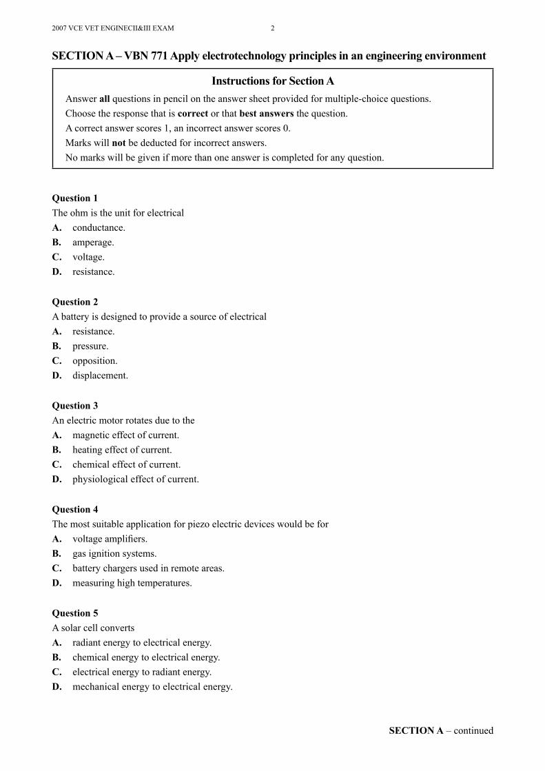
Question 1The ohm is the unit for electricalA. conductance.B. amperage.C. voltage.D. resistance.
Question 2A battery is designed to provide a source of electricalA. resistance.B. pressure.C. opposition.D. displacement.
Question 3An electric motor rotates due to theA. magnetic effect of current.B. heating effect of current.C. chemical effect of current.D. physiological effect of current.
Question 4The most suitable application for piezo electric devices would be forA. voltage ampliÞ ers.B. gas ignition systems.C. battery chargers used in remote areas.D. measuring high temperatures.
Question 5A solar cell convertsA. radiant energy to electrical energy.B. chemical energy to electrical energy.C. electrical energy to radiant energy.D. mechanical energy to electrical energy.
SECTION A � VBN 771 Apply electrotechnology principles in an engineering environment
Instructions for Section AAnswer all questions in pencil on the answer sheet provided for multiple-choice questions.Choose the response that is correct or that best answers the question.A correct answer scores 1, an incorrect answer scores 0.Marks will not be deducted for incorrect answers.No marks will be given if more than one answer is completed for any question.
3 2007 VCE VET ENGINECII&III EXAM
SECTION A � continuedTURN OVER
Question 6A capacitor is a device which is capable of storing an electricA. voltage.B. resistance.C. charge.D. current.
Question 7Devices that rely on magnetism for their operation areA. relays and resistors.B. resistors and capacitors.C. capacitors and transformers.D. transformers and relays.
Question 8A power resistor has 6R8 stamped on its body.This indicates a resistance ofA. 0.68 ΩB. 6.8 ΩC. 68 ΩD. 680 Ω
Question 9A 4.7 kΩ resistor has tolerance of 10%.Its acceptable resistance range is fromA. 4230 to 5170 ΩB. 4465 to 4935 ΩC. 3760 to 5640 ΩD. 4000 to 5400 Ω
Question 10Power used in an electrical circuit is measured inA. volts.B. watts.C. amps.D. ohms.
Question 11Power in a live DC circuit can be determined by combining the readings from two separate instruments. These are theA. voltmeter and wattmeter.B. ammeter and wattmeter.C. ohmmeter and voltmeter.D. ammeter and voltmeter.
2007 VCE VET ENGINECII&III EXAM 4
Question 12A voltmeter is always placedA. in series with electrical components.B. in parallel with electrical components.C. so that total electric current ß ows through it.D. in series with power-consuming devices.
Question 13A low resistance in a circuit will causeA. a high voltage drop.B. a low current.C. a high current.D. the current to fall to zero.
Question 14Excessive current in a circuit will cause a fuse toA. open.B. short.C. reverse polarity.D. conduct to earth.
Question 15A circuit breaker is a switch that operates automatically whenA. normal rated current ß ows.B. circuit current is less than the set rating of the circuit breaker.C. circuit current is greater than the set rating of the circuit breaker.D. an open circuit condition occurs.
END OF SECTION A
5 2007 VCE VET ENGINECII&III EXAM
SECTION B � continuedTURN OVER
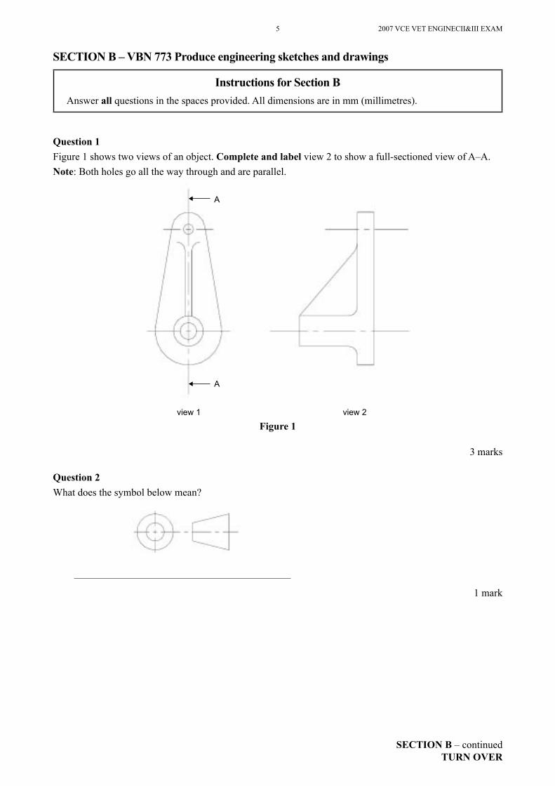
Question 1Figure 1 shows two views of an object. Complete and label view 2 to show a full-sectioned view of A�A.Note: Both holes go all the way through and are parallel.
Figure 1
3 marks
Question 2What does the symbol below mean?
1 mark
SECTION B � VBN 773 Produce engineering sketches and drawings
Instructions for Section BAnswer all questions in the spaces provided. All dimensions are in mm (millimetres).
A
A
view 1 view 2
2007 VCE VET ENGINECII&III EXAM 6
SECTION B � continued
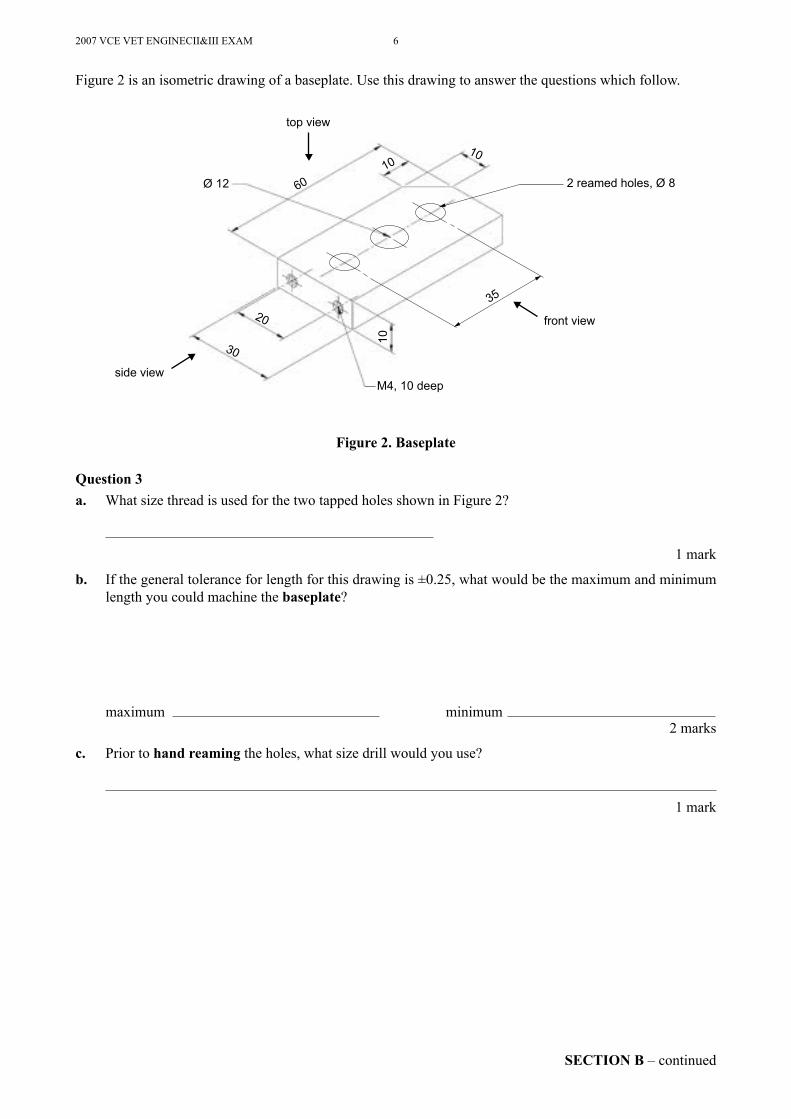
Figure 2 is an isometric drawing of a baseplate. Use this drawing to answer the questions which follow.
Figure 2. Baseplate
Question 3a. What size thread is used for the two tapped holes shown in Figure 2?
1 mark
b. If the general tolerance for length for this drawing is ±0.25, what would be the maximum and minimum length you could machine the baseplate?
maximum minimum2 marks
c. Prior to hand reaming the holes, what size drill would you use?
1 mark
M4, 10 deep
top view
side view
front view
35
2 reamed holes, Ø 8Ø 12
30
20
10
6010
10
7 2007 VCE VET ENGINECII&III EXAM
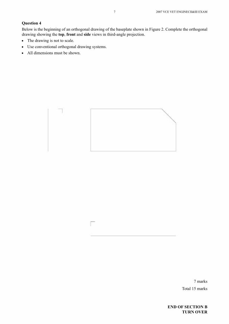
Question 4Below is the beginning of an orthogonal drawing of the baseplate shown in Figure 2. Complete the orthogonal drawing showing the top, front and side views in third-angle projection.• The drawing is not to scale.• Use conventional orthogonal drawing systems.• All dimensions must be shown.
7 marks
Total 15 marks
END OF SECTION BTURN OVER

2007 VCE VET ENGINECII&III EXAM 8
This page is blank
9 2007 VCE VET ENGINECII EXAM
SECTION C � continuedTURN OVER
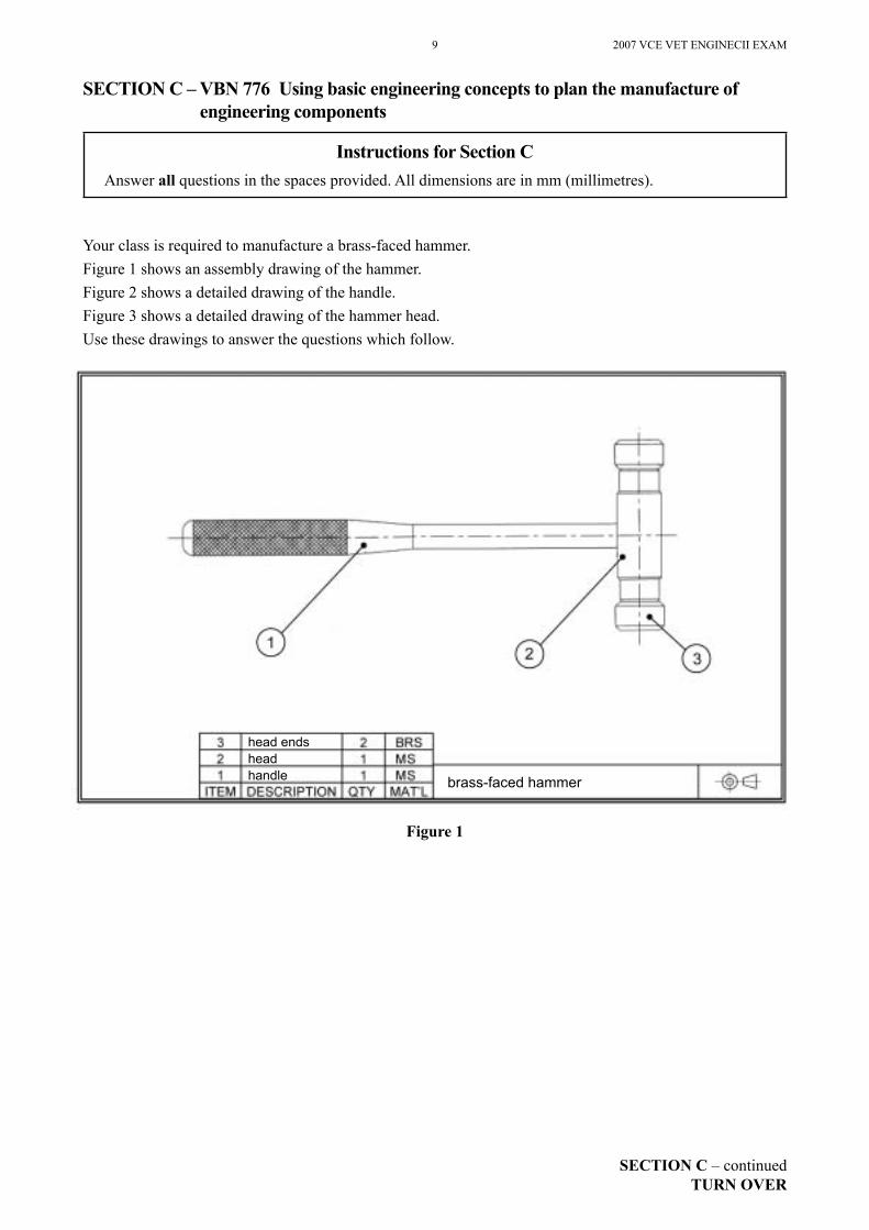
Your class is required to manufacture a brass-faced hammer.Figure 1 shows an assembly drawing of the hammer.Figure 2 shows a detailed drawing of the handle.Figure 3 shows a detailed drawing of the hammer head.Use these drawings to answer the questions which follow.
Figure 1
SECTION C � VBN 776 Using basic engineering concepts to plan the manufacture of engineering components
Instructions for Section CAnswer all questions in the spaces provided. All dimensions are in mm (millimetres).
head endsheadhandle brass-faced hammer
2007 VCE VET ENGINECII EXAM 10
SECTION C � continued
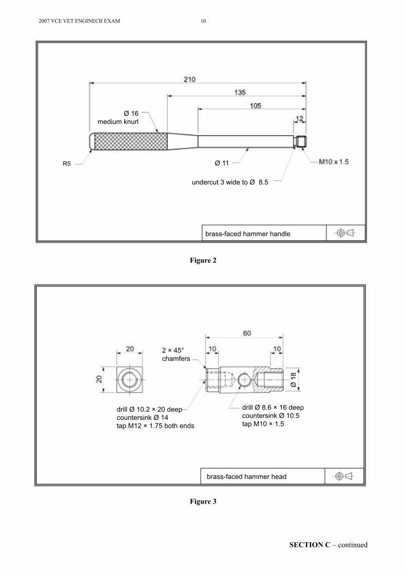
Figure 2
Figure 3
Ø 16medium knurl
Ø 11
undercut 3 wide to Ø 8.5
brass-faced hammer handle
R5
drill Ø 8.6 × 16 deepcountersink Ø 10.5tap M10 × 1.5
drill Ø 10.2 × 20 deepcountersink Ø 14tap M12 × 1.75 both ends
2 × 45°chamfers
brass-faced hammer head
Ø 1
8
11 2007 VCE VET ENGINECII EXAM
SECTION C � continuedTURN OVER
Question 1Before you begin to manufacture the brass-faced hammer (Figure 1), you will need to develop an operational plan.a. Give two reasons why developing an operational plan is important.
i.
1 mark
ii.
1 mark
b. The material for the handle (Figure 2) is being cut from a 3 metre long bar. i. What length should it be cut to?
1 mark
The M10 × 1.5 thread on the handle has an undercut. ii. What is the purpose of the undercut?
1 mark
iii. What tool is used to produce the undercut for the thread?
1 mark
c. What material is used for the hammer head in Figure 3?
1 mark
The M12 threads in the hammer head in Figure 3 must be tapped square to the faces. d. State how this can be achieved when using a centre lathe.
1 mark
e. In Figure 1 the head ends are made of brass. i. Why is brass used?
1 mark
ii. What other material would be suitable for the head ends?
1 mark
2007 VCE VET ENGINECII EXAM 12
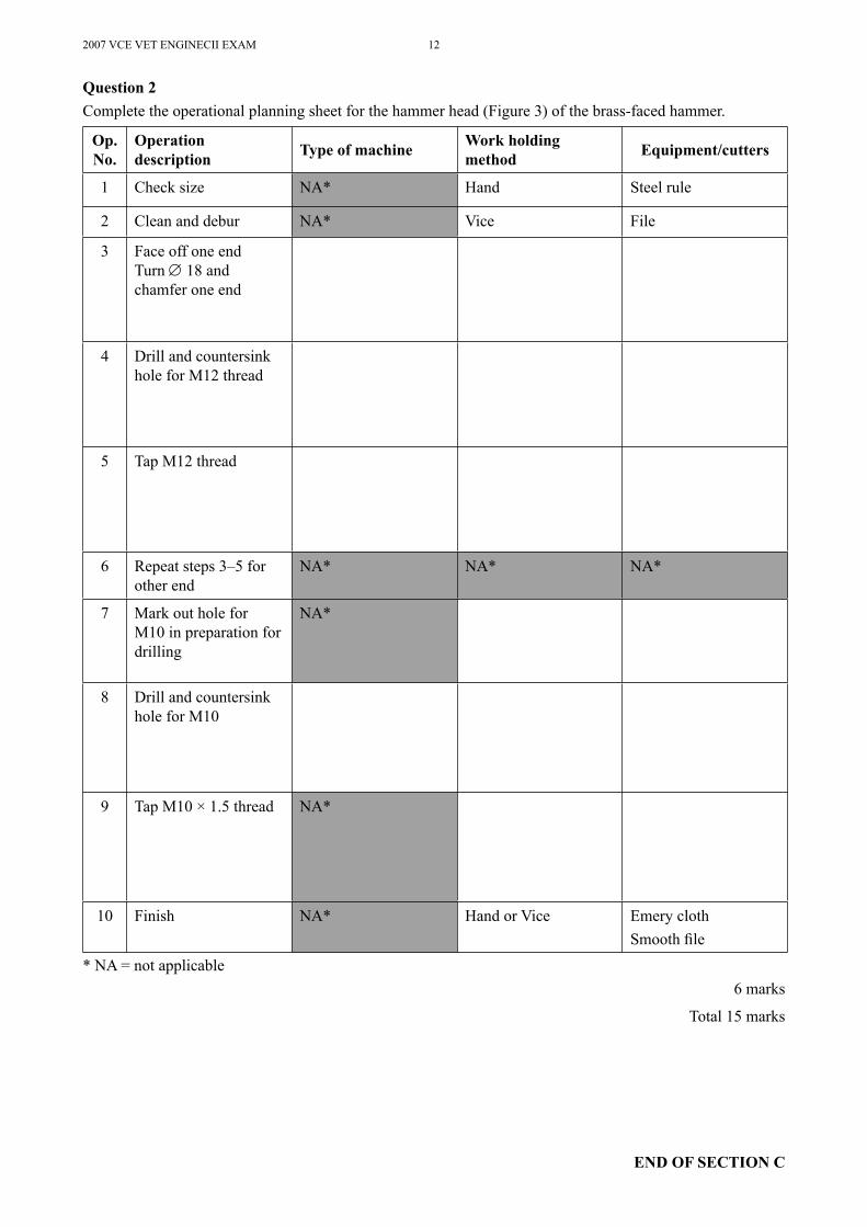
Question 2Complete the operational planning sheet for the hammer head (Figure 3) of the brass-faced hammer.
Op. No.
Operation description Type of machine Work holding
method Equipment/cutters
1 Check size NA* Hand Steel rule
2 Clean and debur NA* Vice File
3 Face off one endTurn ∅ 18 and chamfer one end
4 Drill and countersink hole for M12 thread
5 Tap M12 thread
6 Repeat steps 3�5 for other end
NA* NA* NA*
7 Mark out hole for M10 in preparation for drilling
NA*
8 Drill and countersink hole for M10
9 Tap M10 × 1.5 thread NA*
10 Finish NA* Hand or Vice Emery clothSmooth Þ le
* NA = not applicable6 marks
Total 15 marks
END OF SECTION C
13 2007 VCE VET ENGINECII EXAM
SECTION D � continuedTURN OVER
Question 1Prior to handling, lifting, shifting or setting down of material, you should Þ rst consider safety.Whose safety should you be considering?
1 mark
Question 2What piece of equipment, used in conjunction with a crane, would be used to shift steel sheets from one location to another?
1 mark
Question 3State one of the three main types of slings used for lifting.
1 mark
Question 4A ∅ 50 mild steel bar is being cut to length using a power hacksaw. State one type of injury which could be sustained when handling the sawn lengths.
1 mark
Question 5Wire or rope slings must have a tag attached at one end. State two pieces of information that can be obtained from the tag.
1.
2.
2 marks
SECTION D � VBN 777 Handle engineering materials in a safe and proper manner
Instructions for Section DAnswer all questions in the spaces provided. All dimensions are in mm (millimetres).
2007 VCE VET ENGINECII EXAM 14
SECTION D � continued
Question 6Complete the following table to show the best place to store the materials listed.
Material Storage location
Drums of solvent
Steel sheet, steel plate or bar stock
2 marks
Question 7Who is responsible for producing Material Safety Data Sheets (MSDS)?
1 mark
Question 8State two pieces of information conveyed by a MSDS.
1.
2.2 marks
Question 9Why is it important to know the location and types of Þ re extinguishers available for use in an engineering workshop?
1 mark
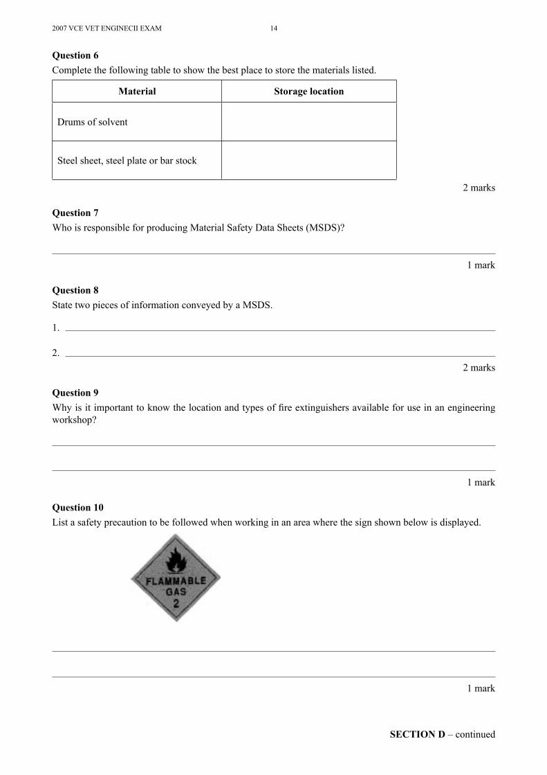
Question 10List a safety precaution to be followed when working in an area where the sign shown below is displayed.
1 mark
15 2007 VCE VET ENGINECII EXAM
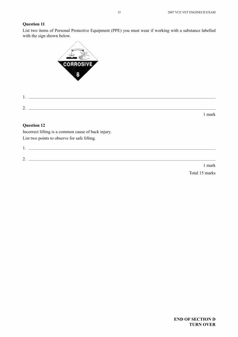
Question 11List two items of Personal Protective Equipment (PPE) you must wear if working with a substance labelled with the sign shown below.
1.
2.1 mark
Question 12Incorrect lifting is a common cause of back injury.List two points to observe for safe lifting.
1.
2.1 mark
Total 15 marks
END OF SECTION DTURN OVER
2007 VCE VET ENGINECII EXAM 16
SECTION E � continued
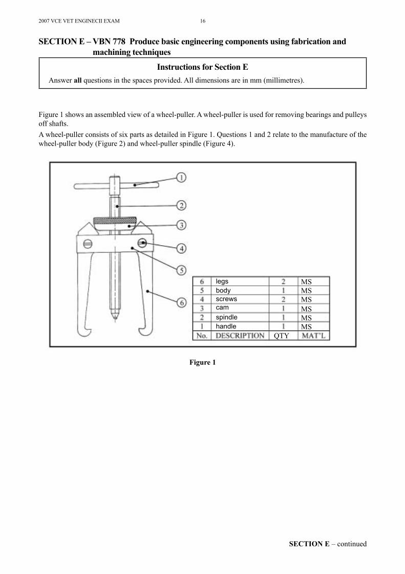
Figure 1 shows an assembled view of a wheel-puller. A wheel-puller is used for removing bearings and pulleys off shafts.A wheel-puller consists of six parts as detailed in Figure 1. Questions 1 and 2 relate to the manufacture of the wheel-puller body (Figure 2) and wheel-puller spindle (Figure 4).
Figure 1
SECTION E � VBN 778 Produce basic engineering components using fabrication and machining techniques
Instructions for Section EAnswer all questions in the spaces provided. All dimensions are in mm (millimetres).
legsbodyscrewscamspindlehandle
MSMSMSMSMSMS
QTY
17 2007 VCE VET ENGINECII EXAM
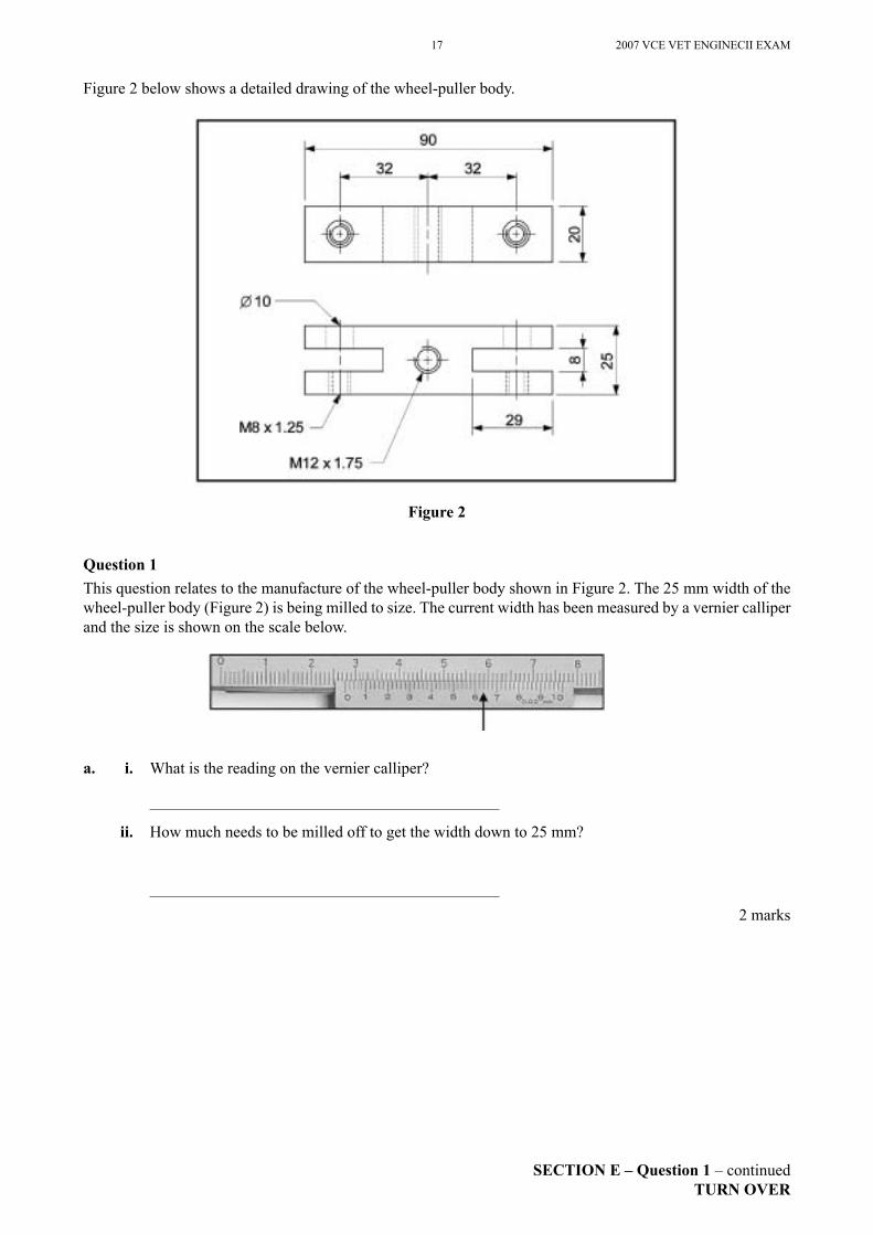
Figure 2 below shows a detailed drawing of the wheel-puller body.
Figure 2
Question 1This question relates to the manufacture of the wheel-puller body shown in Figure 2. The 25 mm width of the wheel-puller body (Figure 2) is being milled to size. The current width has been measured by a vernier calliper and the size is shown on the scale below.
a. i. What is the reading on the vernier calliper?
ii. How much needs to be milled off to get the width down to 25 mm?
2 marks
SECTION E � Question 1 � continuedTURN OVER
2007 VCE VET ENGINECII EXAM 18
b. The 8 mm slots in the body will be milled on a plain (horizontal) milling machine. i. What type of cutter would be suitable to mill the slots?
1 mark
ii. How would you centralise the cutter so that the slot is in the middle of the 25 mm wide wheel puller body?
2 marks
iii. What measuring tool could be used to measure the width of the 8 mm slots accurately to within 0.02 mm?
1 mark
c. What check should be done during the setting up of the vice to ensure the slots are machined parallel to the sides?
1 mark
d. Towards which vice jaw should the pressure of the cutter be directed when milling the slots?
1 mark
e. What check would you do when setting and tightening the wheel-puller body in the vice?
1 mark
SECTION E � Question 1 � continued
19 2007 VCE VET ENGINECII EXAM
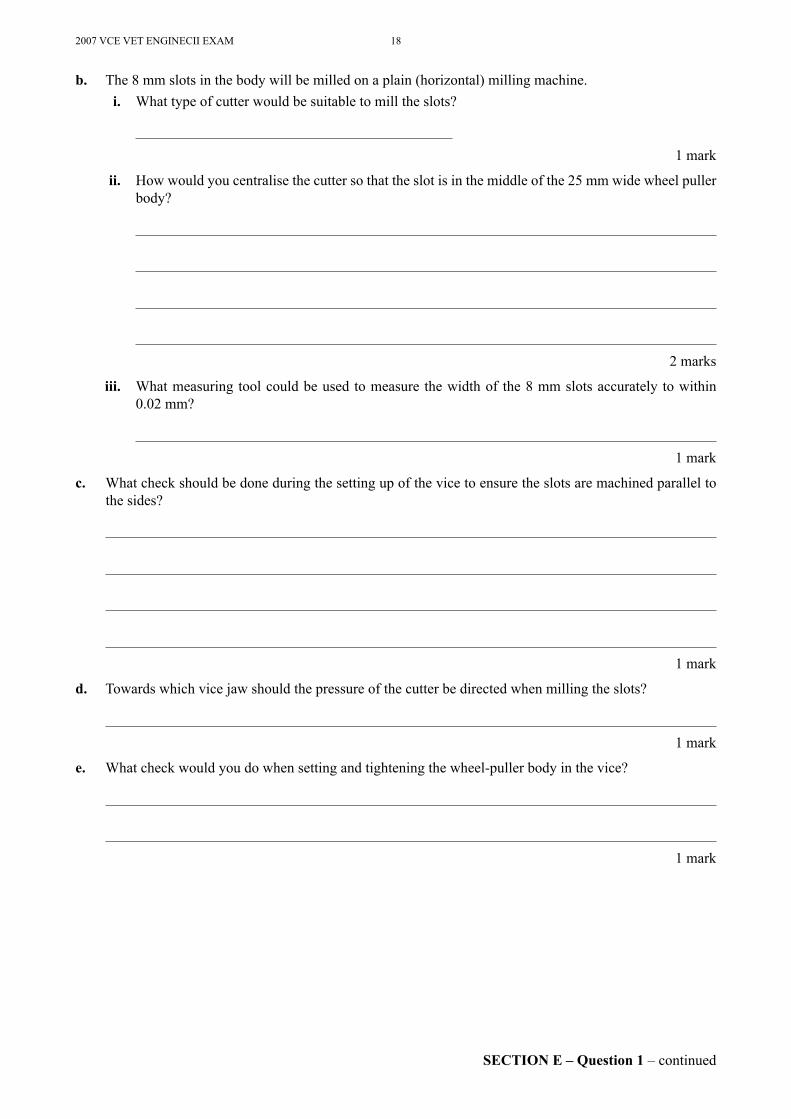
Figure 3 shows a tapping chart.
Figure 3
f. Using the tapping chart, what size hole needs to be drilled for the M8 threads?
1 mark
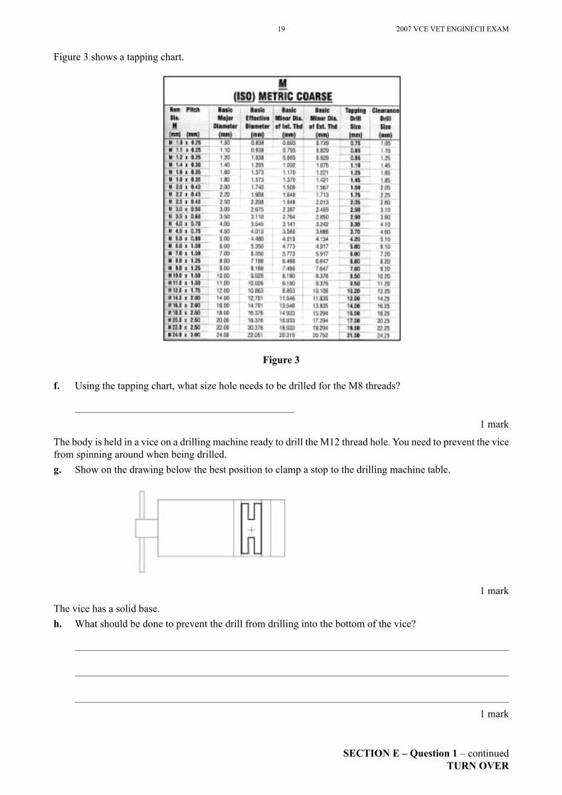
The body is held in a vice on a drilling machine ready to drill the M12 thread hole. You need to prevent the vice from spinning around when being drilled. g. Show on the drawing below the best position to clamp a stop to the drilling machine table.
1 mark
The vice has a solid base. h. What should be done to prevent the drill from drilling into the bottom of the vice?
1 mark
SECTION E � Question 1 � continuedTURN OVER
2007 VCE VET ENGINECII EXAM 20
SECTION E � continued
The twist drill being used for the M12 hole is blunt and needs to be sharpened. The grinder, however, has a glazed wheel. i. How would you rectify this problem?
1 mark
The 10 mm holes and the M8 threaded holes need to line up accurately, so that the screws Þ t. j. Describe how the holes would be set up and drilled to achieve this.
2 marks
21 2007 VCE VET ENGINECII EXAM
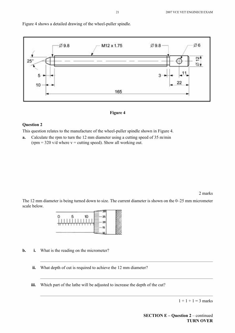
Figure 4 shows a detailed drawing of the wheel-puller spindle.
Figure 4
Question 2This question relates to the manufacture of the wheel-puller spindle shown in Figure 4.a. Calculate the rpm to turn the 12 mm diameter using a cutting speed of 35 m/min
(rpm = 320 v/d where v = cutting speed). Show all working out.
2 marks
The 12 mm diameter is being turned down to size. The current diameter is shown on the 0�25 mm micrometer scale below.
b. i. What is the reading on the micrometer?
ii. What depth of cut is required to achieve the 12 mm diameter?
iii. Which part of the lathe will be adjusted to increase the depth of the cut?
1 + 1 + 1 = 3 marks
SECTION E � Question 2 � continuedTURN OVER
2007 VCE VET ENGINECII EXAM 22
SECTION E � continued
Before using the 0�25 mm micrometer, it should be checked for accuracy. c. Describe how this can be done.
2 marks
d. What part of the lathe is adjusted to machine the 25° taper on the spindle?
1 mark
When turning the spindle, the surface Þ nish produced is too rough. e. From the list (A�D) below, which is the most likely way to improve the surface Þ nish?
A. increase rpmB. reduce rpmC. increase feed rateD. reduce feed rate
1 mark
f. When turning the diameters of the shaft, which part of the lathe is automatically fed?A. cross-slideB. top-slideC. carriageD. tool post
1 mark
g. List two safety hazards that exist when using lathes.
1.
2.
2 marks
h. How can the spindle be securely held on the drilling machine to drill the Ø 6 hole for the handle?
1 mark
23 2007 VCE VET ENGINECII EXAM
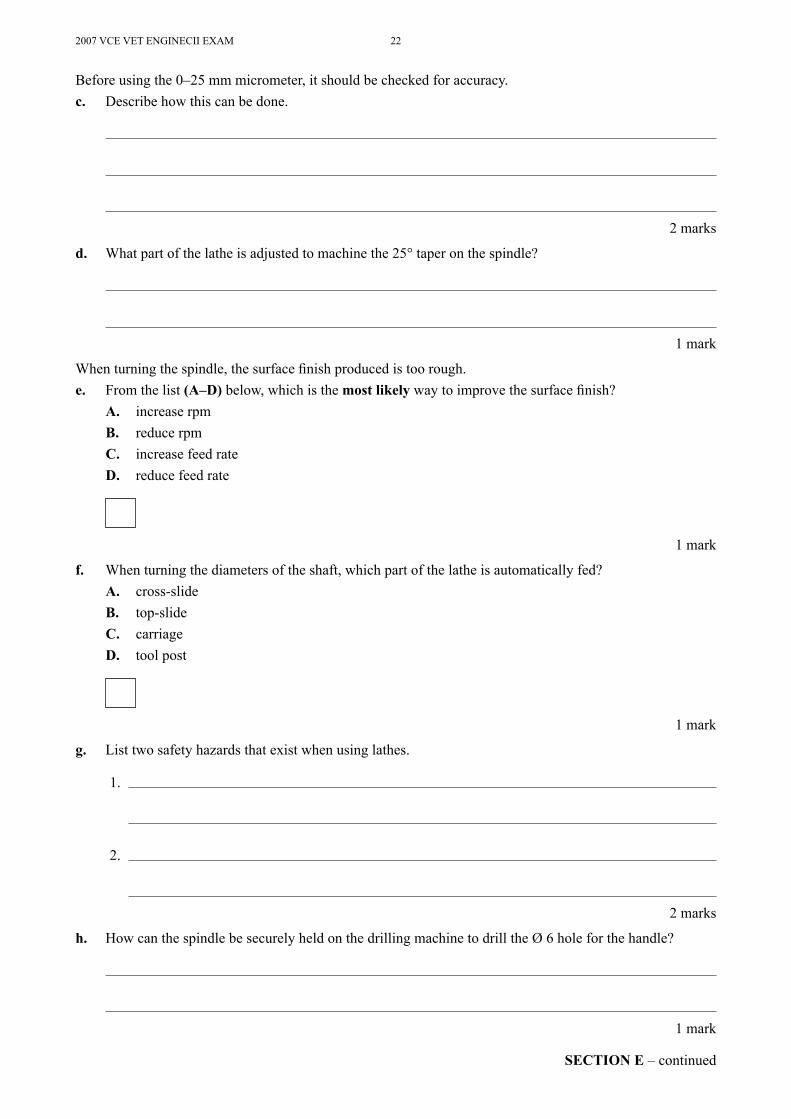
Figure 5 below shows a detailed drawing of a sheet-metal bracket.
Figure 5
Question 3This question relates to the manufacture of the sheet-metal bracket shown in Figure 5.When marking out the bracket on sheet-metal, it is sometimes difÞ cult to see the marked-out lines.a. What can be done to make the lines easier to see?
1 mark
b. What piece of equipment, together with a scriber, is required to mark off the 40° angle on the bracket?
1 mark
c. What marking-out tool is best suited to mark out the radius at the top of the bracket?
1 mark
d. What piece of equipment would be suitable to produce the 90° bend in the bracket?
1 mark
SECTION E � Question 3 � continuedTURN OVER
2007 VCE VET ENGINECII EXAM 24
SECTION E � continued
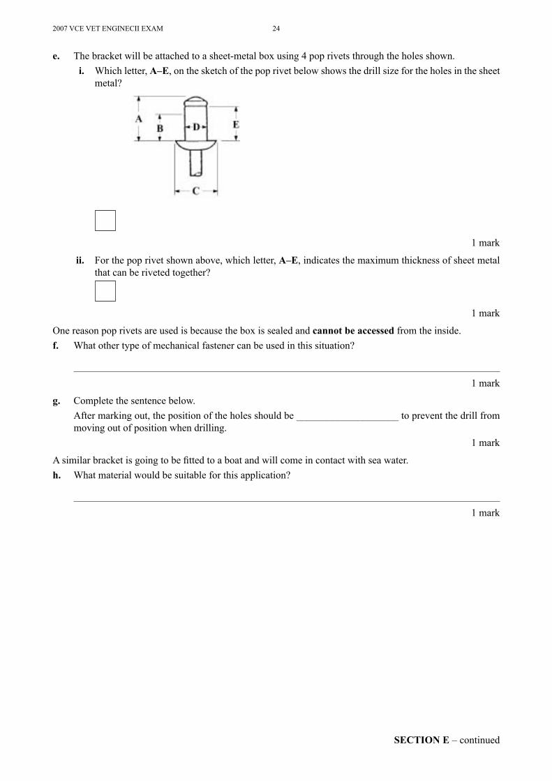
e. The bracket will be attached to a sheet-metal box using 4 pop rivets through the holes shown. i. Which letter, A�E, on the sketch of the pop rivet below shows the drill size for the holes in the sheet
metal?
1 mark
ii. For the pop rivet shown above, which letter, A�E, indicates the maximum thickness of sheet metal that can be riveted together?
1 mark
One reason pop rivets are used is because the box is sealed and cannot be accessed from the inside. f. What other type of mechanical fastener can be used in this situation?
1 mark
g. Complete the sentence below. After marking out, the position of the holes should be ____________________ to prevent the drill from
moving out of position when drilling.1 mark
A similar bracket is going to be Þ tted to a boat and will come in contact with sea water. h. What material would be suitable for this application?
1 mark
25 2007 VCE VET ENGINECII EXAM
END OF QUESTION AND ANSWER BOOK
Question 4a. Four M10 bolts are being used to hold a small electric motor in place. i. What does the �M� stand for?
1 mark
ii. What does the �10� stand for?
1 mark
The motor vibrates when operating, causing the plain washers and nuts to come loose. b. What other type of mechanical fastener can be used to prevent this from happening?
1 mark
Total 40 marks