Embed Size (px)
Citation preview

Driven to Explore
2007 Owner's Manual


~FLEE7W('J()D. Driven to Exp/ore
Fleetwood Enterprises, Inc. All rights reserved. No part of this publication may be reproduced or transmitted in any form or by any means, electronic or mechanical, including photocopying, recording, or by any information storage or retrieval system without written permission from Fleetwood Enterprises, Inc.
IMPORTANT - PLEASE READ: Product information, photography and illustrations included in this manual were as accurate as possible at the time of publication. Materials, design, and specifications are subject to change without notice. Fleetwood has designed its recreational vehicles for a variety of customer uses. Each vehicle features optimal seating, sleeping, storage, and fluid capacities. The user is responsible for selecting the proper combination of loads (i.e. occupants, equipment, fluids, cargo, etc.) to ensure that the vehicle's weight capacities are not exceeded.
Manufacturing subsidiaries of Fleetwood Enterprises, Inc. build the following motor homes and travel trailers: American Eagle' American Heritage' American Tradition' Bounder' Bounder Diesel· Discovery· Excursion· Expedition· Fiesta· Flair· Gearbox· Jamboree' Mallard' Orbit· Pace Arrow· Park Trailer' Pegasus' Pioneer' Pride' Providence· Prowler· Revolution· Revolution LE • Southwind • Storm' Terra' Terry· Tioga' Triumph' Wilderness

,1--
This page intentionally blank.
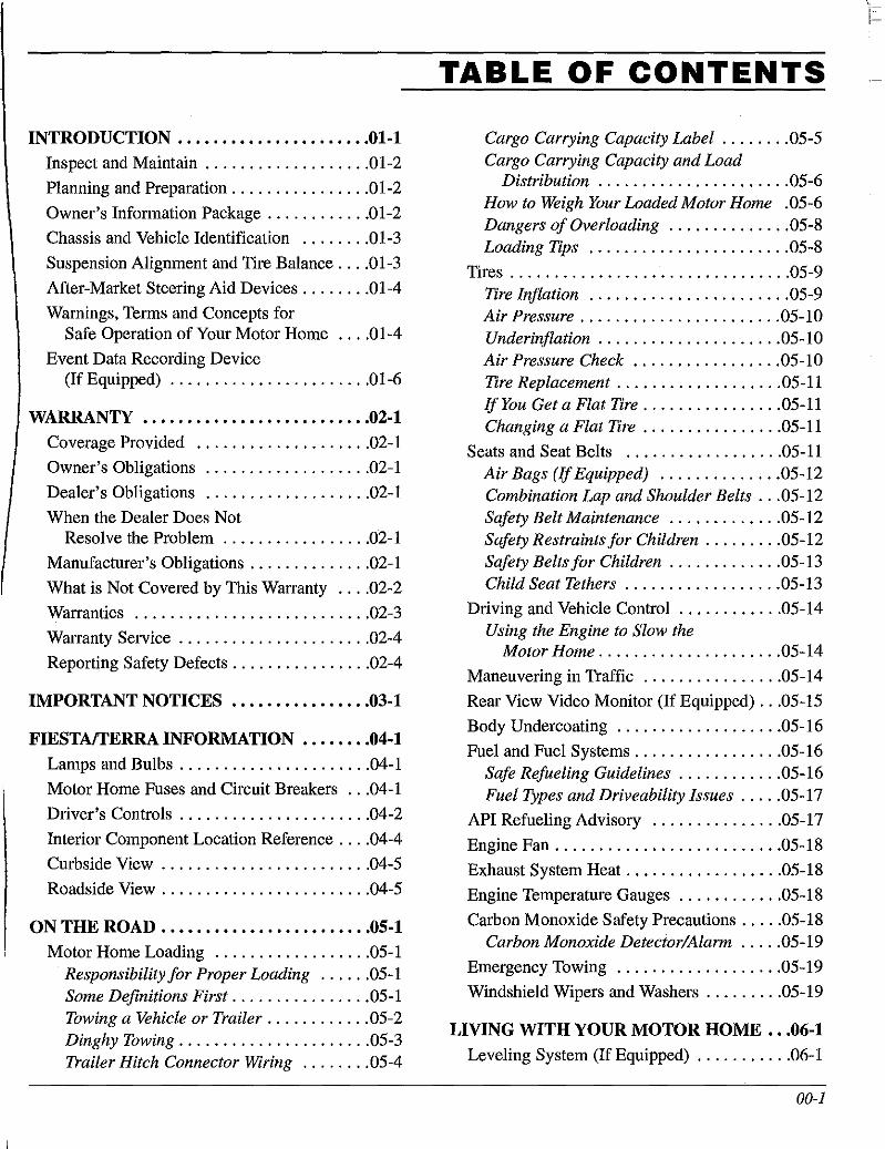
INTRODUCTION . .................... . 01·1
Inspect and Maintain ................... 01-2
Planning and Preparation ................ 01-2
Owner's Information Package ............ 01-2
Chassis and Vehicle Identification ........ 01-3
Suspension Alignment and Tire Balance .... 01-3
After-Market Steering Aid Devices ........ 01-4
Warnings, Terms and Concepts for Safe Operation of Your Motor Home .... 01-4
Event Data Recording Device (If Equipped) ....................... 01-6
WARRANTY .......................... 02 .. 1
Coverage Provided .................... 02-1
Owner's Obligations ................... 02-1
Dealer's Obligations ................... 02-1
When the Dealer Does Not Resolve the Problem ................. 02-1
Manufacturer's Obligations .............. 02-1
What is Not Covered by This Warranty .... 02-2
Warranties ........................... 02-3
Warranty Service ...................... 02-4
Reporting Safety Defects ................ 02-4
IMPORTANT NOTICES ............... . 03·1
FIESTAffERRA INFORMATION ....... . 04·1
Lamps and Bulbs ...................... 04-1
Motor Home Fuses and Circuit Breakers ... 04-1
Driver's Controls ...................... 04-2
Interior Component Location Reference .... 04-4
Curbside View ........................ 04-5
Roadside View ........................ 04-5
ON THE ROAD ........................ 05-1
Motor Home Loading .................. 05-1 Responsibility for Proper Loading ...... 05-1 Some Definitions First . ............... 05-1 Towing a Vehicle or Trailer . ........... 05-2 Dinghy Towing . ..................... 05-3 Trailer Hitch Connector Wiring ........ 05-4
TABLE OF CONTENTS
Cargo Carrying Capacity Label ........ 05-5 Cargo Carrying Capacity and Load
Distribution ...................... 05-6 How to Weigh Your Loaded Motor Home .05·6 Dangers of Overloading .............. 05·8 Loading Tips ....................... 05·8
Tires ................................ 05·9 Tire Inflation ....................... 05-9 Air Pressure . ...................... 05·10 Underinflation ..................... 05· 10 Air Pressure Check . ................ 05·10 Tire Replacement . .................. 05·11 If You Get a Flat Tire . ............ , .. 05·11 Changing a Flat Tire ................ 05· 11
Seats and Seat Belts .................. 05· 11 Air Bags (If Equipped) .............. 05-12 Combination Lap and Shoulder Belts . .. 05·12 Safety Belt Maintenance . ............ 05-12 Safety Restraints for Children . ........ 05·12 Safety Belts for Children ............. 05-13 Child Seat Tethers .................. 05·!3
Driving and Vehicle Control ............ 05·14 Using the Engine to Slow the
Motor Home . ..... , .............. 05·14
Maneuvering in Traffic ................ 05-14
Rear View Video Monitor (If Equipped) ... 05· 15
Body Undercoating ................... 05· 16
Fuel and Fuel Systems ................. 05·16 Safe Refueling Guidelines . ........... 05·16 Fuel Types and Driveability Issues ..... 05· 17
API Refueling Advisory ............... 05· 17
Engine Fan .......................... 05-18
Exhaust System Heat .................. 05·18
Engine Temperature Gauges ............ 05·18
Carbon Monoxide Safety Precautions ..... 05·18 Carbon Monoxide Detector/Alarm . .... 05·19
Emergency Towing ................... 05·19
Windshield Wipers and Washers ......... 05·19
LIVING WITH YOUR MOTOR HOME . . . 06·1
Leveling System (If Equipped) ........... 06· 1
00·1
Table of Contents
Power Entry Step (If Equipped) ", ...... ,06-1
Entry and Screen Doors .... , , , .......... 06-1
Patio Awning (If Equipped) ..... , ........ 06-1
Windows ........... , ........ , ....... 06-2 Emergency Exit Window(s) ............ 06-2
Remote Mirror Control (If Equipped) ...... 06-2
Sun Visors (If Equipped) ............... 06-2
Pull Shades (If Equipped) ............... 06-2 Day/Night Shades (If Equipped) ........ 06-3
Mini-Blinds .......................... 06-3
Storage ........ , .......... , .......... 06-3 Exterior Compartments . .............. 06-3 Interior Storage . .......... , ......... 06-4
Slide-Out Rooms (If Equipped) .......... 06-4
Interior and Furnishings ................ 06-4 Dinette Conversion (with Built-in Table) .. 06-4 Dinette Conversion
(with Free-Standing Table) .......... 06-5 Sofa Conversion (If Equipped) ......... 06-5 Sleeper Sofa Conversion (If Equipped) ... 06-5 Folding Doors/Privacy Curtain
Dividers ..... , ................... 06-5 Folding Chairs (If Equipped) .......... 06-5 Free-Standing Furniture (If Equipped) ... 06-5 Interior Lighting .................... 06-6 Overhead Vents . .................... 06-6
Monitor Panel ........................ 06-6
Effects of Permanent Occupancy ......... 06-7 Condensation and How to Control It '" ,06-7 Dripping Ceiling Vents ............... 06-9
Important Information . , ................ 06-9 What the RV Owner Can Do ..... ..... 06-10
Fire Safety .......................... 06-10 Fire Safety Precautions .............. 06-11 Smoke Detector/Alarm . .............. 06-12
PLUMBING SYSTEMS AND HOLDING TANKS .............. . 07-1
Fresh Water System .................... 07-1 External Fresh Water Hookup . ......... 07-1 Filling the On-Board Water Tank ... . " .07-1 Draining the Fresh Water Tank . ........ 07-2
00-2
1 ___ _ , j:===-
Water Pump . ....................... 07-2 Water Pump Filter . ................ , .07-2 Low Point Drains ................... 07-3 Troubleshooting the Fresh Water System .. 07-3 Leaks . ........ '" ................. 07-3 Sanitizing the Fresh Water System ...... 07-3 Exterior Shower (If Equipped) ......... 07-4 Whole Coach Water Filter System
(If Equipped) ..................... 07-4
Waste Water System ................... 07-4 Toilet ............................. 07-4 Draining the Holding Tanks ........... 07-5 Black Tank Flush System (If Equipped) .. 07-6 Holding Tank Care .................. 07-6 Cold Weather Usage ... .............. 07-7
ELECTRICAL SYSTEMS . ............. . 08-1
Chassis 12-Volt Electrical System ......... 08-1 Chassis Bulbs and Fuses . ............. 08-1
Fleetwood 12-Volt House and Automotive System .... , ........... , ........... 08-1 Batteries . .......................... 08-1 Battery Disconnect (If Equipped) ....... 08-1 Battery Inspection and Care . .... , ..... 08-2 Battery Charging . ................... 08-2 Solar Panel (If Equipped) ............. 08-3 Selecting a Replacement Battery . ....... 08-3 Auxiliary Start System (If Equipped) , .... 08-3
120-Volt System ...................... 08-3
Power Inverter (If Equipped) .......... 08-4 Power Converter . ................... 08-5 Ground Fault Circuit Interrupter (GFCI) .08-5 Generator (If Equipped) .............. 08-5 Generator Fuel Supply ............... 08-5 Propane Generator (If Equipped) ....... 08-5 Generator Operations ................ 08-5 Generator Operating Safety Precautions .. 08-6
Energy Management System -50 AMP For Additional Application ............... 08-7
Electrical Wiring Diagrams ........... , .. 08-7
Motor Home Fuses and Circuit Breakers ... 08-8
Table of Contents
PROPANE SYSTEM . .................. . 09·1 MAINTENANCE . ..................... . 11·1
Propane Safety Precautions .............. 09·1 Exterior ............................. 11-1
System Components ................... 09·2 Stains ., . . . . . . . . . . . . . . . . . . . . . . . .... 11-1
Hoses ............................. 09-2 Exterior Graphics Care . .............. 11-2
Propane Regulator .................. 09-2 Windows, Doors, Vents and Locks . ...... 11-2
Accessory Propane Supply ............ 09-2 TPO Roof System ..................... 11-2
Using Propane System at Low Cleaning . .......................... 11-2 Temperatures ....................... 09-3 Care .. ............................ 11-2
Filling Propane Tanks .................. 09-3 Sealant Renewal .................... 11-2
Propane System Check ................. 09-3
Propane Leak Detector/Alarm ............ 09-3
Lighting Propane Appliances ............ 09-4
Door, Window, Roof Component and Molding Resealing ............. 11-3
Acrylic Assist Handles (If Equipped) ...... 11-3
Interior .............................. 11-3
APPLIANCES ........................ . 10·1 Fabrics . ........................... 11-3
Water Heater ......................... 10-1 Solid Surface Top Care (If Equipped) .... 11-4
Water Heater Bypass Valve ... ......... 10-1
Refrigerator ......................... .10-1
Furnace .............................10-1
Lominate Top Care (If Equipped) ....... 11-4 Walls and Ceiling Panels .. ....... , .... 11-4 Attaching Accessories to Your
Motor Home . ..................... 11-4 Range ............................... 10-2 Plastic/Fiberglass Shower Stall . ........ 11-4 Range Exhaust Hood ................... 10-2 Floors and Carpeting ................ 11-4 Air Conditioner(s) (If Equipped) .......... 10-2 Wood Floor (If Equipped) ............. 11-4
VCR, Televisions, DVD Player Engine Access ...................... 11-5
(If Equipped) ....................... 10-3 Exterior Sealants ...................... 11-5
Additional 12-Volt Equipment ........... 10-3 Generator Filters ...................... 11-5
Video Equipment ...................... 10-3 Maintenance Guideline ................. 11-5
Video Control Center ................... 10-3 STORAGE ............................ 12-1
TV Antenna .......................... 10-3
Antenna Operating Instructions ........... 10-3 Storage Checklists ..................... 12-1
Short-Term Storage (Less than 60 days) .. 12-1 Satellite Dish Antenna (If Equipped) ...... 10-4 Long-Term Storage (Over 60 days) ..... 12-2 Telephone Jack ....................... 10-4 Winterization ......................... 12-2 Microwave Oven (If Equipped) .......... 10-4 Water System Winterizing ............. 12-3 WasherlDryer-Ready Option ............. 10-4 Reactivating the Motor Home Miscellaneous Appliances .............. .1 0-4 After Storage ....................... 12-4
GLOSSARY ........................... 13·1
00-3

1 _____ _
~ ,----
This page intentionally blank.
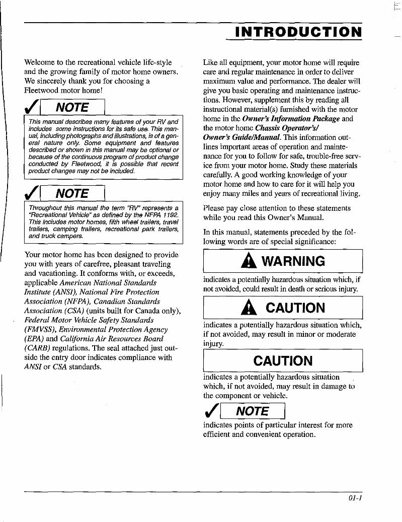
Welcome to the recreational vehicle life-style and the growing family of motor home owners. We sincerely thank you for choosing a Fleetwood motor home!
NOTE J This manual describes many features of your RVand includes some instructions for its safe use. This man· ual, including photographs and illustrations, is of a gen· eral nature only. Some equipment and features described or shown in this manual may be optional or because of the continuous program of product change conducted by Fleetwood, it is possible that recent product changes may not be included.
"'I NOTE 1
Throughout this manual the term "RV" represents a "Recreational Vehicle" as defined by the NFPA 1192. This includes motor homes, fifth wheel trailers, travel trailers, camping trailers, recreational park trailers, and truck campers.
Your motor home has been designed to provide you with years of carefree, pleasant traveling and vacationing. It conforms with, or exceeds, applicable American National Standards Institute (ANSI), National Fire Protection Association (NFPA), Canadian Standards Association (CSA) (units built for Canada only), Federal Motor Vehicle Safety Standards (FMVSS), Environmental Protection Agency (EPA) and California Air Resources Board (CARB) regulations. The seal attached just outside the entry door indicates compliance with ANSI or CSA standards.
INTRODUCTION
Like all equipment, your motor home will require care and regular maintenance in order to deliver maximum value and performance. The dealer will give you basic operating and maintenance instructions. However, supplement this by reading all instructional material(s) furnished with the motor home in the Owner's Information Package and the motor home Chassis Operator's/ Owner's Guide/Manual. This information outlines important areas of operation and maintenance for you to follow for safe, trouble-free service from your motor home. Study these materials carefully. A good working knowledge of your motor home and how to care for it will help you enjoy many miles and years of recreational living.
Please pay close attention to these statements while you read this Owner's Manual.
In this manual, statements preceded by the following words are of special significance:
A WARNING indicates a potentially hazardous situation which, if not avoided, could result in death or serious injury.
A CAUTION indicates a potentially hazardous situation which, if not avoided, may result in minor or moderate injury.
I CAUTION indicates a potentially hazardous situation which, if not avoided, may result in damage to the component or vehicle.
"'I NOTE indicates points of particular interest for more efficient and convenient operation.
01·1
Introduction
If you have any questions regarding operation, maintenance, or service, please contact your dealer immediately so he can assist you. Your dealer's Service or Sales Department will handle any normal problems which might occur.
Some equipment and features described or shown in this manual may be optional or not available on some models.
Because of the continuous program of product improvement conducted by Fleetwood, it is possible that recent product changes may not be included in this manual. Specifications may change without notice. Product information, illustrations and photography included in this Owner's Manual were as accurate as possible at the time of pUblication,' and are representative of function and mayor may not be specific in their depiction of actual equipment, fabrics, interior or exterior decor or design options as installed on or in your recreational vehicle.
The instructions included in this manual are intended as a guide, and in no respect extend the responsibilities of the manufacturing subsidiary, parent company or affiliates beyond the standard written warranty as presented in this manual.
Fleetwood has designed its recreational vehicles to provide a variety of uses for its customers. Each vehicle features optimal seating, sleeping, storage and fluid capacities. The user is responsible for selecting the proper combination of loads to ensure that the recreational vehicle's capacities are not exceeded.
INSPECT AND MAINTAIN
Follow a consistent schedule of inspection and maintenance for your motor home. Your continuing safety and comfort depend on it. This manual includes a section outlining maintenance intervals. If you follow the maintenance guidelines, you will minimize the possibility of failure of any important system or part of your motor home.
01-2
PLANNING AND PREPARATION
Each year millions of Americans embark on trips using some type of recreational vehicle. Proper planning of your trip will ensure a pleasurable experience. A thorough knowledge of your RV is important if you are going to get the most out of the convenience and safety items built into your motor home. Be as familiar with it as you are with your personal car or truck. If you have trouble or have questions, please consult your dealer.
OWNER'S INFORMATION PACKAGE
This package contains valuable documents about your motor home and its equipment and systems. This Owner's Manual and the Chassis Operator's Manual are in the package. Since this manual does not cover every possible detail of equipment and options installed on or in your motor home, there are booklets and instructional material in the package that will help you safely operate, maintain and troubleshoot those items. Be sure you read all this information and understand the safety and operating instructions included in the package. Additionally, you must follow all maintenance instructions to insure full warranty coverage. If you decide to sell or trade your motor home, be sure the new owner receives all the material in this package.
.II NOTE I If your Owner's Information Package does not contain these items, even if you purchased your motor home "used," please call or write Fleetwood and request the desired or missing information.
Fleetwood Motor Home Service P.O. Box 59933
Riverside, CA 92517 1-800-322-8216
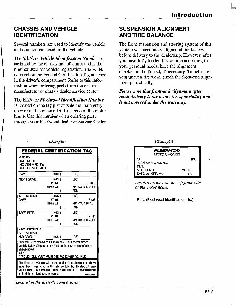
CHASSIS AND VEHICLE IDENTIFICATION
Several numbers are used to identify the vehicle and components used on the vehicle.
The V.I.N. or Vehicle Identification Number is assigned by the chassis manufacturer and is the number used for vehicle registration. The Y.I.N. is found on the Federal Certification Tag attached in the driver's compartment. Refer to this information when ordering parts from the chassis manufacturer or chassis dealer service center.
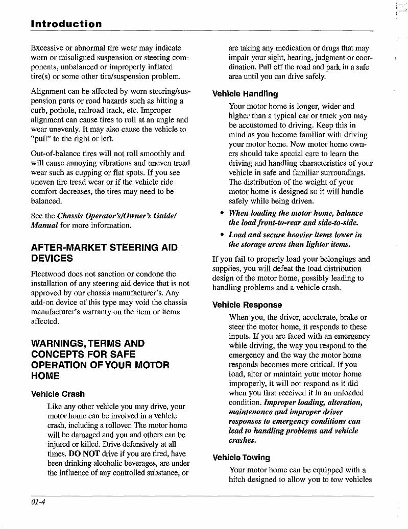
The F.I.N. or Fleetwood Identification Number is located on the tag just outside the main entry door or on the outside left front side of the motor home. Use this number when ordering parts through your Fleetwood dealer or Service Center.
(Example)
FEDERAL CERTIFICATION TAG MFD BY: DATE MFD: INC VEH MFD BY: DATE OF VEH MFD:
GVWR: KGS ( LBS)
FRONTGAWR: KGS ( LBS) WITH: RIMS
TIRES AT: KPA COLD SINGLE ( PSI)
INTERMEDIATE KGS ( LBS) GAWR: WITH: RIMS
TIRES AT: KPA COLD DUAL ( PSI)
GAWR REAR: KGS ( LBS) WITH: RIMS
TIRES AT: KPA COLD SINGLE ( PSI)
GAWR COMBINED INTERMEDIATE AND REAR: KGS ( LBS)
This vehicle conforms to all applicable U.S. Federal Motor Vehicle Safety Standards in effect on the date of manufactUre shown above: V.I.N. TYPE VEHICLE: MULTI-PURPOSE PASSENGER VEHICLE
The tires and wheels with sizes and ratings designated above have been equipped with this vehicle by Fleetwood. Any replacement tires installed must meet the same specifications and minimum load requirements. W15-0016
Located in the driver's compartment.
Introduction
SUSPENSION ALIGNMENT AND TIRE BALANCE
The front suspension and steering system of this vehicle was accurately aligned at the factory before delivery to the dealership_ However, after you have fully loaded the vehicle according to your personal needs, have the alignment checked and adjusted, if necessary. To help prevent uneven tire wear, check the front -end alignment periodically_
Please note that front-end alignment after retail delivery is the owner's responsibility and is not covered under the warranty.
(Example)
FLEElWOOD. MOTOR HOMES
OF PLAN APPROVAL NO.
- F.I.N. MFD.ID. NO. DATE OF MFA. MO:
INC.
MODEL YR:
Located on the exterior left front side of the motor home.
- F.I.N. (Fleetwood Identification No.)
01-3
I~
Introduction
Excessive or abnormal tire wear may indicate worn or misaligned suspension or steering components, unbalanced or improperly inflated tire(s) or some other tire/suspension problem.
Alignment can be affected by worn steering/suspension parts or road hazards such as hitting a curb, pothole, railroad track, etc. Improper alignment can cause tires to roll at an angle and wear unevenly. It may also cause the vehicle to "pull" to the right or left.
Out-of-balance tires will not roll smoothly and will cause annoying vibrations and uneven tread wear such as cupping or flat spots. If you see uneven tire tread wear or if the vehicle ride comfort decreases, the tires may need to be balanced.
See the Chassis Operator's/Owner's Guide/ Manual for more information.
AFTER-MARKET STEERING AID DEVICES
Fleetwood does not sanction or condone the installation of any steering aid device that is not approved by our chassis manufacturer's. Any add-on device of this type may void the chassis manufacturer's warranty on the item or items affected.
WARNINGS, TERMS AND CONCEPTS FOR SAFE OPERATION OF YOUR MOTOR HOME
Vehicle Crash
01-4
Like any other vehicle you may drive, your motor home can be involved in a vehicle crash, including a rollover. The motor home will be damaged and you and others can be injured or killed. Drive defensively at all times. DO NOT drive if you are tired, have been drinking alcoholic beverages, are under the influence of any controlled substance, or
are taking any medication or drugs that may impair your sight, hearing, judgment or coordination. Pull off the road and park in a safe area until you can drive safely.
Vehicle Handling
Your motor home is longer, wider and higher than a typical car or truck you may be accustomed to driving. Keep this in mind as you become familiar with driving your motor home. New motor home owners should take special care to learn the driving and handling characteristics of your vehicle in safe and familiar surroundings. The distribution of the weight of your motor home is designed so it will handle safely while being driven.
• When loading the motor home, balance the load front-to-rear and side-to-side.
• Load and secure heavier items lower in the storage areas than lighter items.
If you fail to properly load your belongings and supplies, you will defeat the load distribution design of the motor home, possibly leading to handling problems and a vehicle crash.
Vehicle Response
When you, the driver, accelerate, brake or steer the motor home, it responds to these inputs. If you are faced with an emergency while driving, the way you respond to the emergency and the way the motor home responds becomes more critical. If you load, alter or maintain your motor home improperly, it will not respond as it did when you first received it in an unloaded condition. Improper loading, alteration, maintenance and improper driver responses to emergency conditions can lead to handling problems and vehicle crashes.
Vehicle Towing
Your motor home can be equipped with a hitch designed to allow you to tow vehicles
or other loads behind your motor home. The maximum amount of weight your motor home can pull or stop is determined by the manufacturer of the chassis on which your motor home is built. Check the Chassis Operator'sIOwner's Guidel Manual provided by the motor home chassis manufacturer for the limits on the weight you can tow.
til NOTE I In most cases the GCWR of the chassis and the finished motor home are the same. In some cases, due to the equipped hitch receiver, the GCWR may be reduced. Please refer to the Cargo Carrying Capacity Tag posted in your motor home for the rated GCWR.
If the Chassis Operator'sIOwner's Guidel Manual equipped with your motor home does not provide specific information on towing weight limits, it is strongly recommended that the towed vehicle or trailer be equipped with a properly installed and operating supplemental brake control system that operates in combination with the brakes on your motor home.
o You may be able to increase the weight of any towed load by properly installing on the towed load a supplemental brake control system that operates with your motor home's braking system. Even with additional brakes, you cannot tow more than the GTW or GCWR for the chassis under your motor home. Again, check the Chassis Operator'sIOwner's GuidelManuaL
o You CANNOT increase the towed weight limit by changing the size of your hitch.
o Properly load what you tow to avoid a vehicle crash.
o Do not attempt to tow something that is too heavy for your chassis.
o When driving in mountainous areas, look for and obey highway signs concerning grades and curves. Your driving experience when pulling and stopping a
Introduction
towed unit on mountain roads will be very different from what you experience on level ground.
o State laws in the United States and provinciallaws in Canada vary concerning towing requirements and limits. Check the laws in the areas where you anticipate traveling.
Alterations to Your Motor Home
Many motor home owners like to add a personal touch to their motor home. But there is a difference between changing how your motor home looks versus how it handles or responds to driver inputs. If you expect to make any type of alteration to your motor home, consult a professional who understands the correct way to do the alteration and how the alteration will change or affect the stability, handling, vehicle response, and overall performance and safety of your motor home. An improper alteration that affects vehicle handling or response can cause a vehicle crash, and any improper alteration to the electrical or Propane systems can cause a fire and can endanger your motor home and its occupants. Fleetwood, your chassis and other manufacturers stand behind the motor home as delivered - NOT as altered by someone else.
Warning Devices
Your motor home is equipped with warning devices. Check them before a trip for proper operation. A disabled warning device cannot warn you or vehicle occupants of a life-threatening danger. Keep them working and respond to them quickly.
Examples of These Devices Include:
o Carbon Monoxide Detector! Alarm
o Propane Detector! Alarm
o Smoke Detector! Alarm
o Seat Belt Warnings
o Hazard Flashers
01-5
Introduction
• Brake Warning Light
• Engine Warning Light
EVENT DATA RECORDING DEVICE (If Equipped)
SPECIAL NOTICE: Vehicle Event Data Recording Capabilities.
Motor homes equipped with driver/passenger airbags, Navigational or Vehicle Avoidance Systems and/or equipped with certain other electronic devices may be equipped with event data recording capabilities.
Your motor home is built on a vehicle chassis supplied by an automotive manufacturer. For diagnostic and safety related reasons, this chassis comes equipped with electronic modules (devices).
01-6
Certain electronic modules have the capability to record information about the vehicle, driver, and passenger such as engine performance, braking performance, vehicle location, vehicle speed, and occupant seat belt use, or other data.
The data stored in the electronic modules may be retrieved by authorized parties using specialized equipment, for vehicle diagnostic or accident investigation purposes.
Please refer to the chassis manufacturer owner's guide and/or (if equipped) electronic device manufacturers owner's guide(s), for further details on event data recording capabilities.
, ,--):===
LIMITED ONE-YEAR/THREE YEAR WARRANTY For Motor Homes Manufactured and Warranted by subsidiaries of Fleetwood
Enterprises, Inc., sold in the United States and Canada
COVERAGE PROVIDED
Your new motor home, including the structure, plumbing, heating and electrical systems, all appliances and equipment installed by the manufacturer, is warranted under normal use to be free from manufacturing defects in material or workmanship. Appearance imperfections, or damage to paint, graphics, exterior materials, or upholstery that may have occurred prior to delivery are normally corrected during the inspection process at the manufacturing plant or at the dealership.
The warranty extends to the first retail purchaser and his transferee(s) and begins on the date of original retail delivery or the date the motor home is first placed into service as a rental, commercial or demonstrator unit (whichever occurs first). The warranty extends for the following periods:
1. For all defects (other than structural) the warranty extends for a period of one year from such date or until the unit has received 15,000 total miles of use as detennined by the mileage shown on the odometer (whichever occurs first).
2. For structural defects, 3 years/50,000 miles; structural defects are limited to the following: roof structure, sub-floor structure, and Vacu-bond® walls.
Written notice of defects must be given to the selling dealer or manufacturer not later than ten (l0) days after the expiration of the warranty period.
OWNER'S OBLIGATIONS
The owner is responsible for normal maintenance as described in the Owner's Information Package; however, minor adjustments (such as adjustments to the interior or exterior doors, Propane regulator pressure, cabinet latches, TV
antenna control, etc.) will be performed by the dealer during the first 90 days of warranty coverage. Thereafter, such adjustments are the responsibility of the owner as normal maintenance unless required as a direct result of repair or replacement of a defective part under this warranty.
If a problem occurs which the owner believes is covered by this warranty, the owner shall contact the selling dealer, or Fleetwood Owner Relations, giving sufficient information to resolve the matter. The owner shall deliver the motor home to an Authorized Fleetwood Dealer for warranty service.
DEALER'S OBLIGATIONS
By agreement with the manufacturer, the dealer is obligated to maintain the motor home prior to retail sale, to perform a detailed predelivery inspection and to repair or replace any parts necessary to correct defects in material or workmanship.
WHEN THE DEALER DOES NOT RESOLVE THE PROBLEM
If the dealer is unable or unwilling to resolve a problem which the owner is convinced is covered by the warranty, the owner should contact Fleetwood Owner Relations at the address or telephone number listed on the next page and provide Fleetwood Owner Relations with a description of the problem and attempts made to resolve it.
MANUFACTURER'S OBLIGATIONS
Upon receipt of notice of a claim, where the dealer was unable or unwilling to resolve the problem, a Fleetwood Service Center will repair or replace any parts necessary to correct defects in material or workmanship or will take other appropriate action as may be required.
02-1
Warranty
WHAT IS NOT COVERED BY THIS WARRANTY
This warranty does not cover:
1. The automotive chassis system (including the chassis and drive train), tires and batteries, which are covered by the separate warranties of the respective manufacturers of these components.
2. Defects caused by or related to:
a. Abuse, misuse, negligence or accident;
b. Failure to comply with instructions contained in the Owner's Information Package;
c. Alteration or modification of the motor home;
d. Environmental conditions (salt, hail, chemicals in the atmosphere, etc.)
3. Normal deterioration due to wear or exposure, such as fading of fiberglass, fabrics or drapes, carpet wear, etc.
4. Normal maintenance and service items, such as light bulbs, fuses, wiper blades, lubricants, etc.
5. Motor homes on which the odometer reading has been altered.
6. Transportation to and from dealer or Fleetwood Service Center location, loss of time, inconvenience, commercial loss, loss of use, towing charges, bus fares, vehicle rental, incidental charges such as telephone calls or hotel bills, or other incidental or consequential damages.
7. Fleetwood will NOT be responsible for any losses, damages, or claims, including, but not limited to, property damage, personal injury, loss of income, legal fees or expenses, emotional distress, death, loss
02-2
of use, loss of value, all other economic loss, adverse health effects, or any other effects caused or alleged to be caused by MICROBIAL MATTER, including, but not limited to, mold, mildew, fungus or dry rot.
THE IMPLIED WARRANTIES ARE LIMITED IN DURATION TO THE EXPRESS TERMS· OF THIS 1/3 YEAR WARRANTY.
Some states do not allow the exclusion or limitation of incidental or consequential damages, so the above limitation or exclusion may not apply to you.
This warranty gives you specific legal rights, and you may also have other rights which vary from state to state.
The manufacturer/warrantor is not responsible for any undertaking, representation or warranty made by any dealer or other person beyond those expressly set forth in this warranty.
For Motor Homes Manufactured and Warranted by the following subsidiaries of Fleetwood Enterprises, Inc.:
Fleetwood Motor Homes of California, Inc. Fleetwood Motor Homes of Indiana, Inc.
Fleetwood Motor Homes of Pennsylvania, Inc.
For Customer Service assistance, contact:
Fleetwood Owner Relations P.O. Box 59933
Riverside, CA 92517 1-800-322-8216
Ford Chassis Assistance: 1-800-444-3311
Workhorse Chassis Assistance: 1-877-294-6773
FreightIiner Chassis Assistance: 1-800-385-4357
Chevrolet Division of General Motors Chassis Assistance:
1-800-222-1020
WARRANTIES
Your motor home is covered by one of the most comprehensive warranty programs in the RV industry. Please refer to the warranty in this section. It explains your rights and obligations, as well as the rights and obligations of the dealer and manufacturer. Please read this section carefully. You will be better informed in case you have a warranty-related problem, and your dealer will be better able to get you on the road again. If you have any questions about the warranty or what it does or does not cover, please contact your dealer.
The materials in your Owner's Information Package contain warranty information and operating instructions on the various appliances and components in your motor home. Warranty registration cards for these items should be filled out and mailed as soon as possible after you take delivery of your motor home. If you do not have operating instructions for a particular appliance or component, contact your dealer.
You will automatically receive an Ownercare Card several weeks after the delivery receipt is received from your selling dealer. This card is imprinted with your name, the motor home serial number, and manufacturing subsidiary location. If your motor home ever needs warranty service, present this card to the dealer, or have it available when contacting Fleetwood's Owner Relations Group.
The motor home has been thoroughly inspected before shipment. Your dealer is responsible for performing a complete predelivery inspection of the motor home as specified in the Ownercare delivery checkout.
As a part of the predelivery inspection procedure, the dealer is responsible for road testing the motor home, noting and correcting any steering problems and setting correct tire pressures before delivery.
Fleetwood and its subsidiaries will not be responsible for front end alignment after this
Warranty
predelivery inspection has been performed.
You should return your motor home to the selling dealer for warranty service. If this is not possible, you may contact any other authorized Fleetwood motor home dealer. The service department at any of the locations listed at the back of this manual can help you find a dealer in your area.
If, for some reason, a problem is not handled to your satisfaction:
1. Discuss any warranty-related problems directly with the manager and/or owner of the dealership, giving them an opportunity to help the service department resolve the matter for you.
2. If a problem arises that has not been resolved to your satisfaction by your local dealer, contact Fleetwood Owner Relations. The locations are listed in the back of this manual. Please contact the one nearest you.
3. We sincerely believe that your dealer and the factory representative will be able to solve any problem which might arise. If their combined efforts are not satisfactory, please send a letter describing the circumstances to:
Fleetwood Owner Relations P.O. Box 59933
Riverside, CA 92517
Please include the brand name and serial number of your motor home. The serial number is located on the identification tag next to the entry door, and on your warranty card.
4. If you wish to call for assistance, please use this toll-free telephone number:
Fleetwood Owner Relations 1-800-322-8216
There may be times when your motor home will need repairs or parts while you are on the road. If your motor home is repaired by a non-authorized repair facility (non-Fleetwood dealer), be sure to save receipts and especially any parts that are replaced. These parts will usually have to be returned to your dealer before you can be reimbursed for their cost.
02-3
Warranty
WARRANTY SERVICE
If you need service or warranty information, please see the booklets and other documents included in your Owner's Information Package. When contacting any of the equipment manufacturers, always have the model and serial numbers available. Appliance identification numbers will be found on tags or plates attached to the appliance.
If you ever need warranty work done, be sure to have the right papers with you. If required work is not covered under the warranty, your dealer's service department can help you with getting the correct service. Always keep a maintenance log of your RV's service history.
Always make a written list of the RV's problems or the specific work you want done. If you've had work done that is not on your maintenance log, let the service advisor know. Don't keep secrets.
And finally, be reasonable with requests. If you have a long list of service items that need attention and you need your RV very soon, discuss the situation with the service advisor, listing the items in order of priority. This will help the service department manage their time and will help get you going as quickly as possible.
If you have a warranty or service concern about the chassis portion of your vehicle please be aware that you may go directly to an authorized chassis dealer for service. This may save you time and effort as the chassis warranty is administered by the chassis manufacturer. Consult your area phone directory for an authorized dealer and make arrangements with their service department. If you are unsure if the concern is chassis related, feel free to contact your Fleetwood dealer to assist you.
REPORTING SAFETY DEFECTS
If you believe that your vehicle has a defect which could cause a crash, injury, or death, you should immediately inform the National
02-4
Highway Traffic Safety Administration (NHTSA) in addition to notifying the Fleetwood Owner Relations at 1-800-322-8216.
If NHTSA receives similar complaints, it may open an investigation, and if it finds that a safety defect exists in a group of vehicles, it may order a recall and remedy campaign.
To contact NHTSA, you may either call the Auto Safety Hotline toll-free at 1-888-327-4236 or write to:
NHTSA U.S. Department of Transportation
400 Seventh St. SW Washington, DC 20590
You can also obtain other information about motor vehicle safety from the Hotline.
i-t:=
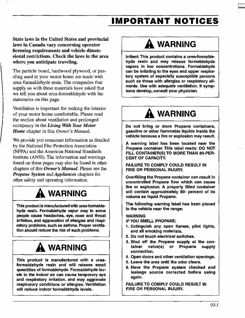
State laws in the United States and provincial laws in Canada vary concerning operator licensing reqnirements and vehicle dimensional restrictions. Check the laws in the area where you anticipate traveling.
The particle board, hardwood plywood, or paneling used in your motor home are made with urea-formaldehyde resin. The companies that supply us with these materials have asked that we tell you about urea-formaldehyde with the statements on this page.
Ventilation is important for making the interior of your motor home comfortable. Please read the section about ventilation and prolonged occupancy in the Living With Your Motor Home chapter in this Owner's Manual.
We provide you consumer information as detailed by the National Fire Protection Association (NFPA) and the American National Standards Institute (ANSI). The information and warnings found on these pages may also be found in other chapters of this Owner's Manual. Please see the Propane System and Appliances chapters for other safety and operating information.
A WARNING This product is manufactured with urea-formalde-hyde resin. Formaldehyde vapor may in some people cause headaches, eye, nose and throat irritation, and aggravation of allergies and respi-ratory problems, such as asthma. Proper ventila-tion should reduce the risk of such problems.
A WARNING This product is manufactured with a urea-formaldehyde resin and will release small quantities of formaldehyde. Formaldehyde lev-els in the indoor air can cause temporary eye and respiratory irritation, and may aggravate respiratory conditions or allergies. Ventilation will reduce indoor formaldehyde levels.
IMPORTANT NOTICES
A WARNING Irritant: This product contains a urea-formaldehyde resin and may release formaldehyde vapors in low concentrations. Formaldehyde can be irritating to the eyes and upper respiratory system of especially susceptible persons such as those with allergies or respiratory ailments. Use with adequate ventilation. If symptoms develop, consult your physician.
A. WARNING Do not bring or store Propane containers, gasoline or other flammable liquids inside the vehicle because a fire or explosion may result.
A warning label has been located near the Propane container. This label reads: DO NOT FILL CONTAINER(S) TO MORE THAN aO-PERCENT OF CAPACITY.
FAILURE TO COMPLY COULD RESULT IN FIRE OR PERSONAL INJURY.
Overfilling the Propane container can result in uncontrolled Propane flow which can cause fire or explosion. A properly filled container will contain approximately ao- percent of its volume as liquid Propane.
The following warning label has been placed in the vehicle near the range:
WARNING IFYOU SMELL PROPANE: 1. Extinguish any open flames, pilot lights,
and all smoking materials. 2. Do not touch electrical switches. 3. Shut off the Propane supply at the con
tainer valve(s) or Propane supply connection.
4. Open doors and other ventilation openings. 5. Leave the area until the odor clears. 6. Have the Propane system checked and
leakage source corrected before using again.
FAILURE TO COMPLY COULD RESULT IN FIRE OR PERSONAL INJURY.
03-1
Important Notices
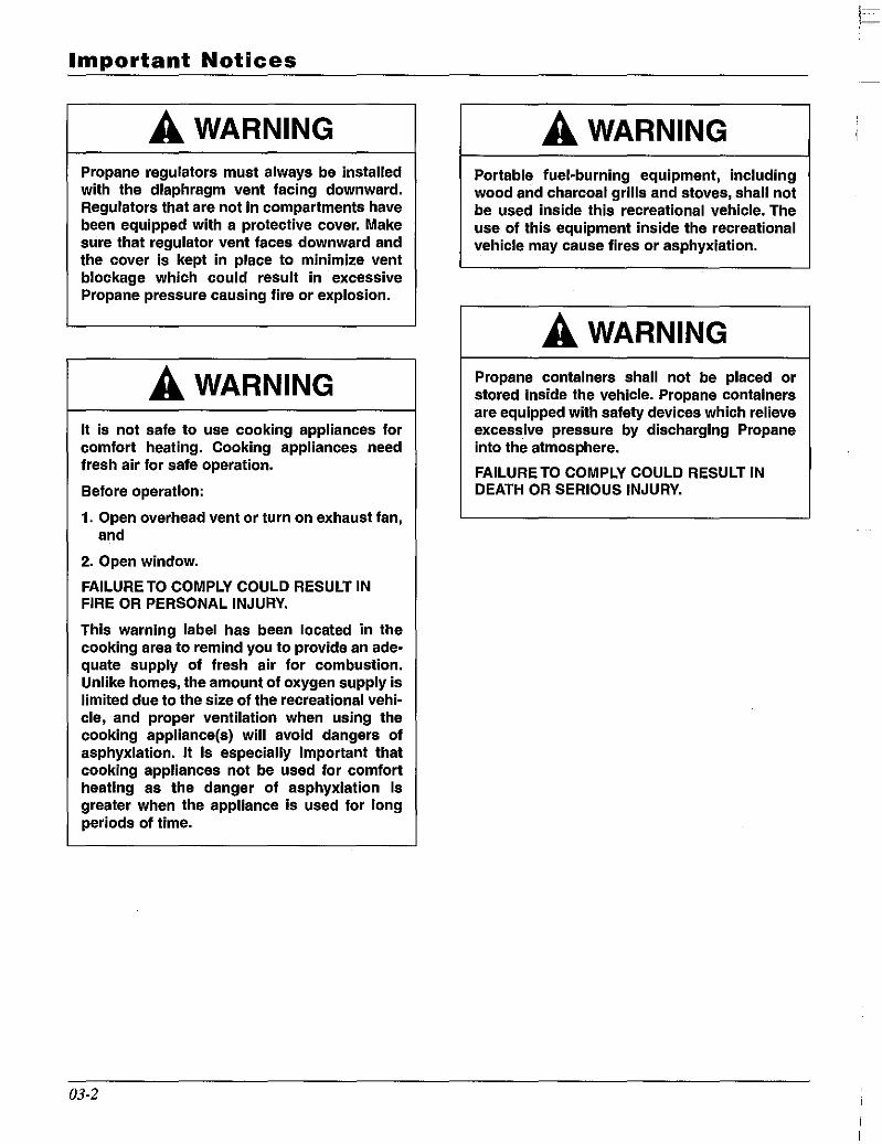
it.. WARNING Propane regulators must always be installed with the diaphragm vent facing downward. Regulators that are not in compartments have been equipped with a protective cover. Make sure that regulator vent faces downward and the cover is kept in place to minimize vent blockage which could result in excessive Propane pressure causing fire or explosion.
A WARNING It is not safe to use cooking appliances for comfort heating. Cooking appliances need fresh air for safe operation.
Before operation:
1. Open overhead vent or turn on exhaust fan, and
2. Open window.
FAILURE TO COMPLY COULD RESULT IN FIRE OR PERSONAL INJURY.
This warning label has been located in the cooking area to remind you to provide an adequate supply of fresh air for combustion. Unlike homes, the amount of oxygen supply is limited due to the size of the recreational vehicle, and proper ventilation when using the cooking appliance(s) will avoid dangers of asphyxiation. It is especially important that cooking appliances not be used for comfort heating as the danger of asphyxiation is greater when the appliance is used for long periods of time.
03-2
A WARNING Portable fuel-burning equipment, including wood and charcoal grills and stoves, shall not be used inside this recreational vehicle. The use of this equipment inside the recreational vehicle may cause fires or asphyxiation.
A WARNING Propane containers shall not be placed or stored inside the vehicle. Propane containers are equipped with safety devices which relieve excessive pressure by discharging Propane into the atmosphere.
FAILURE TO COMPLY COULD RESULT IN DEATH OR SERIOUS INJURY.
---I r=
FIESTA/TERRA INFORMATION
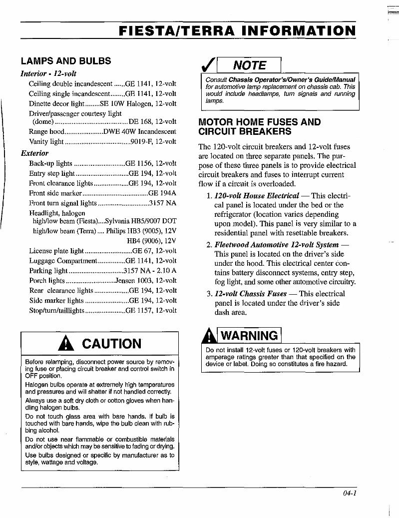
LAMPS AND BULBS Interior - I2-volt
Ceiling double incandescent ...... GE 1141. 12-volt
Ceiling single incandescent... ..... GE 1141. 12-volt
Dinette decor light.. ...... SE lOW Halogen. 12-volt
Driver/passenger courtesy light (dome) ........................................ DE 168. 12-volt
Range hood ..................... DWE 40W Incandescent
Vanity light .................................... 9019-F. 12-volt
Exterior Back-up lights ............................ GE 1156. 12-volt
Entry step light ............................. GE 194. 12-volt
Front clearance lights ................... GE 194. 12-volt
Front side marker .................................... GE 194A
Front tum signal lights ........................... .3157 NA
Headlight. halogen high/low beam (Fiesta) .... Sylvania HB5/9007 DOT
high/low beam (Terra) .... Philips HB3 (9005). 12V
HB4 (9006). 12V
License plate light.. ........................ GE 67. 12-volt
Luggage Compartment ............... GE 1141. 12-volt
Parking light. ............................ .3157 NA - 2.10 A
Porch lights ........................... Jensen 1003. 12-volt
Rear clearance lights ................... GE 194. 12-volt
Side marker lights ........................ GE 194. 12-volt
Stop/turn/taillights ...................... GE 1157. 12-volt
A. CAUTION Before relamping. disconnect power source by removing fuse or placing circuit breaker and control switch in OFF position.
Halogen bulbs operate at extremely high temperatures and pressures and will shatter if not handled correctly.
Always use a soft dry cloth or cotton gloves when handling halogen bulbs.
Do not touch glass area with bare hands. If bulb is touched with bare hands. wipe the bulb clean with rubbing alcohol.
Do not use near flammable or combustible materials and/or objects which may be sensitive to fading or drying.
Use bulbs designed or specific by manufacturer as to style. wattage and Voltage.
NOTE I Consult Chassis Operator'sIOwner's GuidelManual for automotive lamp replacement on chassis cab. This would include headlamps, turn signals and running lamps.
MOTOR HOME FUSES AND CIRCUIT BREAKERS
The 120-volt circuit breakers and 12-volt fuses are located on three separate panels. The purpose of these three panels is to provide electrical circuit breakers and fuses to interrupt current flow if a circuit is overloaded.
1. I20-volt House Electrical- This electrical panel is located under the bed or the refrigerator (location varies depending upon model). This panel is very similar to a residential panel with resettable breakers.
2. Fleetwood Automotive I2-volt System -This panel is located on the driver's side under the hood. This electrical center contains battery disconnect systems. entry step. fog light. and some other automotive circuitry.
3. I2-volt Chassis Fuses - This electrical panel is located under the driver's side dash area.
WARNING Do not install 12-volt fuses or 120-volt breakers with amperage ratings greater than that specified on the device or label. Doing so constitutes a fire hazard.
04-1
1-=--f-==
i--f=
Fiesta/Terra Information
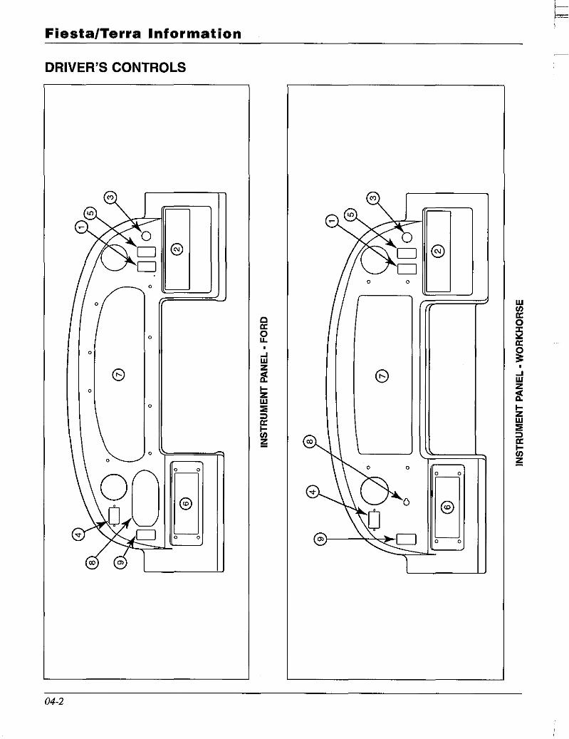
DRIVER'S CONTROLS
0 w en Q a:
0 a: :I: 0 0 ~ u. a: •
~ 0 ...J W Z • e ~ e ...J
w I- Z
0 Z ~ W
0 ::E I-:l Z a: w I- ::E en :l 2!: co a:
I-0 en
0 2!: 0 0 0
0 0
e 0 e 0 0 0 0 0
04-2
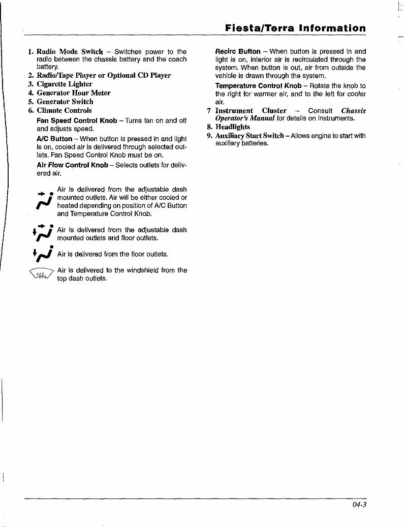
1. Radio Mode Switch - Switches power to the radio between the chassis battery and the coach battery.
2. Radio/Tape Player or Optional CD Player 3. Cigarette Lighter 4. Generator Hour Meter 5. Generator Switch 6. Climate Controls
Fan Speed Control Knob - Turns fan on and off and adjusts speed.
AlC Button - When button is pressed in and light is on, cooled air is delivered through selected outlets. Fan Speed Control Knob must be on.
Air Flow Control Knob - Selects outlets for delivered air.
Air is delivered from the adjustable dash :i mounted outlets. Air will be either cooled or ,- heated depending on position of AlC Button
and Temperature Control Knob .
• ;; Air is delivered from the adjustable dash mounted outlets and floor outlets .
• • r1 Air is delivered from the floor outlets.
~ Air is delivered to the windshield from the top dash outlets.
Fiesta/Terra Information
Recirc Button - When button is pressed in and light is on, interior air is recirculated through the system. When button is out, air from outside the vehicle is drawn through the system.
Temperature Control Knob - Rotate the knob to the right for warmer air, and to the left for cooler air.
7 Instrument Cluster Consult Chassis Operator's Manual for details on instruments.
8. Headlights 9. Auxiliary Start Switch - Allows engine to start with
auxiliary batteries.
04-3
Fiesta/Terra Information
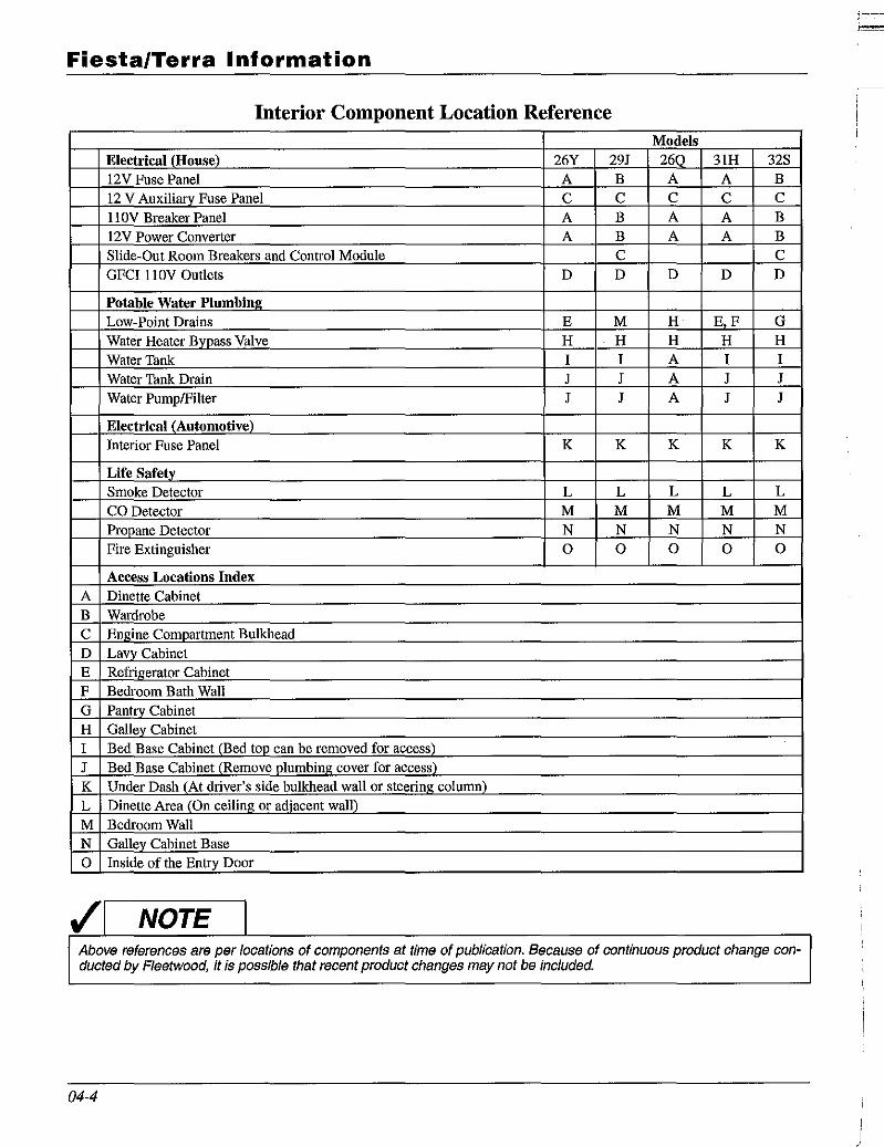
Interior Component Location Reference Models
Electrical (House) 26Y 29J 26Q 3tH 32S 12V Fuse Panel A B A A B 12 V Auxiliary Fuse Panel C C C C C H OV Breaker Panel A B A A B 12V Power Converter A B A A B Slide-Out Room Breakers and Control Module C C GFCI HOV Outlets D D D D D
Potable Water Plumbiull Low-Point Drains E M H E,F G Water Heater Bypass Valve H H H H H Water Tank I I A I I Water Tank Drain J J A J J Water Pump/Filter J J A J J
Electrical (Automotive) Interior Fuse Panel K K K K K
Life Safety Smoke Detector L L L L L
CO Detector M M M M M Propane Detector N N N N N Fire Extinguisher 0 0 0 0 0
Access Locations Iudex A Dinette Cabinet B Wardrobe C Engine Compartment Bulkbead D Layy Cabinet E Refrigerator Cabinet F Bedroom Bath Wall G PantrY Cabinet H Galley Cabinet I Bed Base Cabinet (Bed top can be removed for access) J Bed Base Cabinet (Remove plumbing cover for access) K Under Dash (At driver's side bulkbead wall or steering column) L Dinette Area (On ceiling or adjacent wall) M Bedroom Wall N Galley Cabinet Base 0 Inside of the Entry Door
v'1 NOTE I Above references are per locations of components at time of publication. Because of continuous product change conducted by Fleetwood, it is possible that recent product changes may not be included.
04-4
J
Fiesta/Terra Information
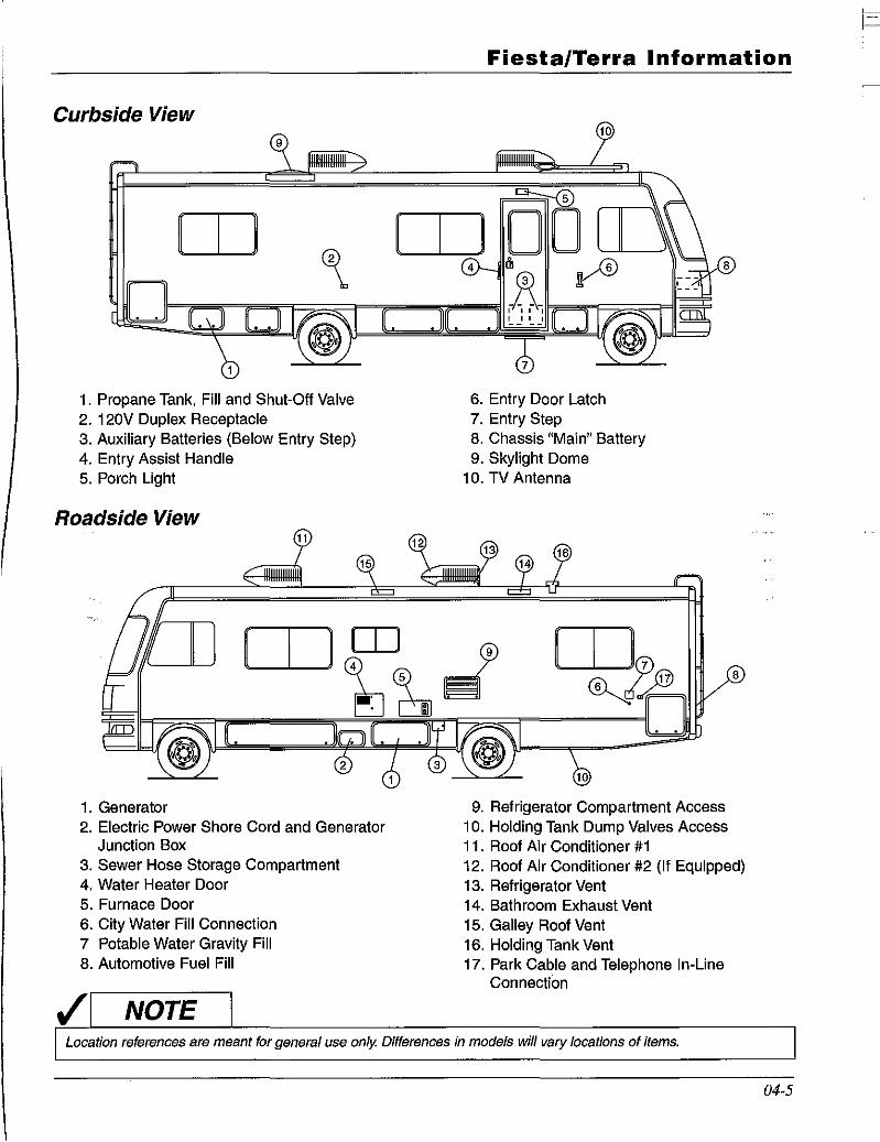
Curbside View 10
CD 4 ~
DIi=7i=-~~~~""'i\iF""~. )1
1. Propane Tank, Fill and Shut-Off Valve 2. 120V Duplex Receptacle 3. Auxiliary Batteries (Below Entry Step) 4. Entry Assist Handle 5. Porch Light
Roadside View
1. Generator 2. Electric Power Shore Cord and Generator
Junction Box 3. Sewer Hose Storage Compartment 4. Water Heater Door 5. Furnace Door 6. City Water Fill Connection 7 Potable Water Gravity Fill 8. Automotive Fuel Fill
NOTE
6. Entry Door Latch 7. Entry Step 8. Chassis "Main" Battery 9. Skylight Dome
10. TV Antenna
9. Refrigerator Compartment Access 10. Holding Tank Dump Valves Access 11. Roof Air Conditioner #1 12. Roof Air Conditioner #2 (If Equipped) 13. Refrigerator Vent 14. Bathroom Exhaust Vent 15. Galley Roof Vent 16. Holding Tank Vent 17. Park Cable and Telephone In-Line
Connection
Location references are meant for general use only. Differences in models will vary locations of items.
04-5

This page intentionally blank.
I ,--(= ,
i I
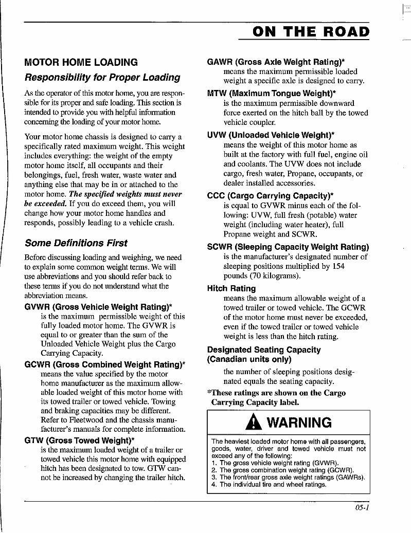
MOTOR HOME LOADING
Responsibility for Proper Loading
As the operator of this motor home, you are responsible for its proper and safe loading. This section is intended to provide you with helpful information concerning the loading of your motor home.
Your motor home chassis is designed to carry a specifically rated maximum weight. This weight includes everything: the weight of the empty motor home itself, all occupants and their belongings, fuel, fresh water, waste water and anything else that may be in or attached to the motor home. The specified weights must never be exceeded. If you do exceed them, you will change how your motor home handles and responds, possibly leading to a vehicle crash.
Some Definitions First Before discussing loading and weighing, we need to explain some common weight terms. We will use abbreviations and you should refer back to these terms if you do not understand what the abbreviation means.
GVWR (Gross Vehicle Weight Rating)' is the maximum permissible weight of this fully loaded motor home. The GVWR is equal to or greater than the sum of the Unloaded Vehicle Weight plus the Cargo Carrying Capacity.
GCWR (Gross Combined Weight Rating)' means the value specified by the motor home manufacturer as the maximum allowable loaded weight of this motor home with its towed trailer or towed vehicle. Towing and braking capacities may be different. Refer to Fleetwood and the chassis manufacturer's manuals for complete information.
GTW (Gross Towed Weight)" is the maximum loaded weight of a trailer or towed vehicle this motor home with equipped hitch has been designated to tow. GTW cannot be increased by changing the trailer hitch.
ON THE ROAD
GAWR (Gross Axle Weight Rating)' means the maximum permissible loaded weight a specific axle is designed to carry.
MTW (Maximum Tongue Weight)' is the maximum permissible downward force exerted on the hitch ball by the towed vehicle coupler.
UVW (Unloaded Vehicle Weight)" means the weight of this motor home as built at the factory with full fuel, engine oil and coolants. The UVW does not include cargo, fresh water, Propane, occupants, or dealer installed accessories.
CCC (Cargo Carrying Capacity)' is equal to GVWR minus each of the following: UVW, full fresh (potable) water weight (including water heater), full Propane weight and SCWR.
SCWR (Sleeping Capacity Weight Rating) is the manufacturer's designated number of sleeping positions multiplied by 154 pounds (70 kilograms).
Hitch Rating means the maximum allowable weight of a towed trailer or towed vehicle. The GCWR of the motor home must never be exceeded, even if the towed trailer or towed vehicle weight is less than the hitch rating.
Designated Seating Capacity (Canadian units only)
the number of sleeping positions designated equals the seating capacity.
*These ratings are shown on the Cargo Carrying Capacity label.
A. WARNING The heaviest loaded motor home with all passengers, goods, water, driver and towed vehicle must not exceed any of the following: 1. The gross vehicle weight rating (GVWR). 2. The gross combination weight rating (GCWR). 3. The front/rear gross axle weight ratings (GAWRs). 4. The individual tire and wheel ratings.
05-1
On The Road
Towing a Vehicle or Trailer ("Towed Load or Towed Unit'J
til NOTE I Some states and provinces require brakes and safety chains .. whe,n towing vehicles. Consult the proper authonUes In the states or provinces through which you will be traveling.
When you use your motor home to tow, remember that you must stop the towed load with your motor home's brakes. This is critical on hills and in the mountains where you may encounter sharp curves and possibly irregular road surfaces. Check your motor home Chassis Operator's/Owner's Guide/Manual for the maximum weight your motor home can pull and stop on both level and steep roads.
til NOTE I In most cases the GCWR of the chassis and the finished motor home are the same. In some cases, due to the equipped hitch receiver, the GCWR may be reduced. Please refer to the Cargo Carrying Capacity Tag posted in your motor home for the rated GCWR.
If the Chassis Operator's/Owner's Guide/Manual equipped with your motor home does not provide specific information on towing weight limits, it is strongly recommended that the towed vehicle or trailer be equipped with a properly installed and operating supplemental brake control system that operates in combination with the brakes on your motor home. The supplemental brakes will NOT allow you to tow more than the listed GCWR for your motor home. If you cannot stop, you will crash.
You must not exceed the tire capacities or the weight factors listed below if you expect to tow something behind your motor home, either with or without a dolly. The factors are:
• GCWR - Gross Combined Weight Rating
• GTW - Gross Towed Weight
• MTW - Maximum Tongue Weight
• GAWR - Gross Axle Weight Rating
The ratings for the above factors are all listed
05-2
on the Cargo Carrying Capacity label posted inside the motor home.
• Tire Capacity
The tire capacity is dependent upon the inflation pressure set at the load applied.
If you expect to tow with your motor home, there are additional guidelines that you must follow:.Do not use a load equalizing hitch if your hitch head receiver is below 10,000 lbs. capacity. It could cause structural damage to the motor home frame components.
• Do not exceed Maximum Tongue Weight as listed on the carrying capacity label. Heavier tongue weights can change your vehicle's handling and response, can cause a vehicle to crash, and will restrict your coverage under the Ownercare Warranty.
• Consult with your dealer or towing equipment/trailer supplier to determine the correct type of hitch head assembly and equipment you should use for towing and leveling the load you intend to pull.
• Do not tow anything weighing more than the GTW listed on the Cargo Carrying Capacity label. Heavier towed loads can exceed your chassis' ability to pull and stop the load and cause a vehicle crash, damage the motor home structure or drive train, and restrict your coverage under the Fleetwood or chassis manufacturer's warranty. Changing the trailer hitch will not increase the tow capacity of the motor home.
• Consult the Chassis Operator's/Owner's Guide/Manual, and U.S. state and Canadian provincial laws for towing weight limits and for guidelines for installing supplemental braking systems that operate with your motor home's brakes.
it.. WARNING Do not exceed the rated load of the motor home, or the rated load of any axle. Exceeding the GVWR GAWR, GTW or GCWR of your motor home ca~ cause handling problems, a vehicle crash, damage your motor home and void your warranties.
I ~~ /-- ,--
The way your motor home handles and responds will be affected by the way the towed unit is loaded. If the tongue weight is too light in relations to the GTW, handling and response will change and your motor home will operate less safely. Careful load planning and safe experimentation with different loading patterns in what you are towing can avoid this risk and make your driving and towing experience safer and more enjoyable.
Your motor home is equipped with one-half of the equipment required to tow a trailer, automobile dolly, or other towed load.
The equipment supplied with your motor home is called the "hitch receiver". This component is attached to the motor home frame. The square tube opening "receives" any of a wide variety of hitch head assemblies. The "hitch head" is the component that includes the hitch ball.
Hitch head assemblies are available in both "Weight-Distributing" (load-equalizing) and "Weight-Carrying" types. A weight-distributing hitch.uses spring bars attached to the trailer tongue A-frame assembly to transfer some of the trailer tongue weight to both motor home axles.
A weight-carrying hitch head assembly does not use spring bars. All of the tongue weight of the trailer bears down on the hitch assembly which loads the motor home rear axle. For this reason, the maximum load you can tow with a weight carrying hitch head assembly is limited.
In addition to weight-carrying and weight-distributing, your hitch may also have a dinghy towing rating. This rating will apply should you tow a motor vehicle with all four wheels down.
The ratings associated with the particular hitch receiver supplied with your motor home are noted on the weight tag and on a label affixed to the hitch receiver.
It is important that the devices which attach to the hitch receiver equipped with your motor
On The Road
home are rated to equal or exceed the loads of your towed trailer, automobile dolly, or other towed load.
The weight label on your hitch receiver provides the maximum trailer weight rating and the maximum tongue weight rating. It is important that these ratings not be exceeded.
Consult with your dealer or towing equipment/trailer supplier to determine the correct type of hitch head assembly, hitch ball and equipment you should use for towing and leveling the load you intend to pull.
Dinghy Towing
When a motorized vehicle is towed behind a motor home with all four tires on the ground, the towed vehicle is often referred to as a "dinghy". Vehicle manufacturers produce tow" able cars and trucks that are designed to be capable of being towed behind a larger vehicle, such as a motor home, with all wheels down.
Caution should be exercised when selecting a vehicle for dinghy towing. If not, battery drain on the electrical system could occur, the transmission of the vehicle could be damaged, the vehicle may be too heavy to pull, among other concerns.
Before selecting the vehicle that will be towed, consult the vehicle manufacturers instructions to ensure the vehicle is approved by the manufacturer for dinghy (four wheels down) towing. Any aftermarket products that modify the dinghy for towing should also be approved by the vehicle manufacturer.
Make sure that the dinghy weight and attaching hardware do not exceed the motor home hitch receiver rating. Make sure that the weight of the motor home and dinghy together; do not exceed the gross combination weight rating (GCWR) of
05-3
On The Road
the motor home. Make sure that tow bars and hitch equipment is rated to handle the weight of the vehicle you intend to tow.
In addition, the dinghy must be equipped with its own independent auxiliary brake system that is activated any time the motor home brakes are applied.
Because of State/Province regulations, care must be exercised when wiring the dinghy for all lighting requirements.
Check with the DMV of your State and/or States (and Provinces) you will be traveling through for their requirements.
05-4
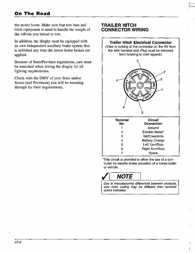
TRAILER HITCH CONNECTOR WIRING
Trailer Hitch Electrical Connector (View is looking at the connector on the RV from
the wire harness end. Plug must be removed from housing to view legend.)
3
7
4 5
1
6
2
Terminal Circuit No. Connection 1 Ground 2 Electric Brake' 3 Tail/Clearance 4 Battery Charge 5 Left Turn/Stop 6 Right Turn/Stop 7 Spare
'This circuit is provided to allow the use of a controller for electric brake actuation of a towed trailer or vehicle.
tl'1 NOTE I Due to manufacturing differences between products, wire color coding may be different than terminal colors indicated.
I
L
On The Road
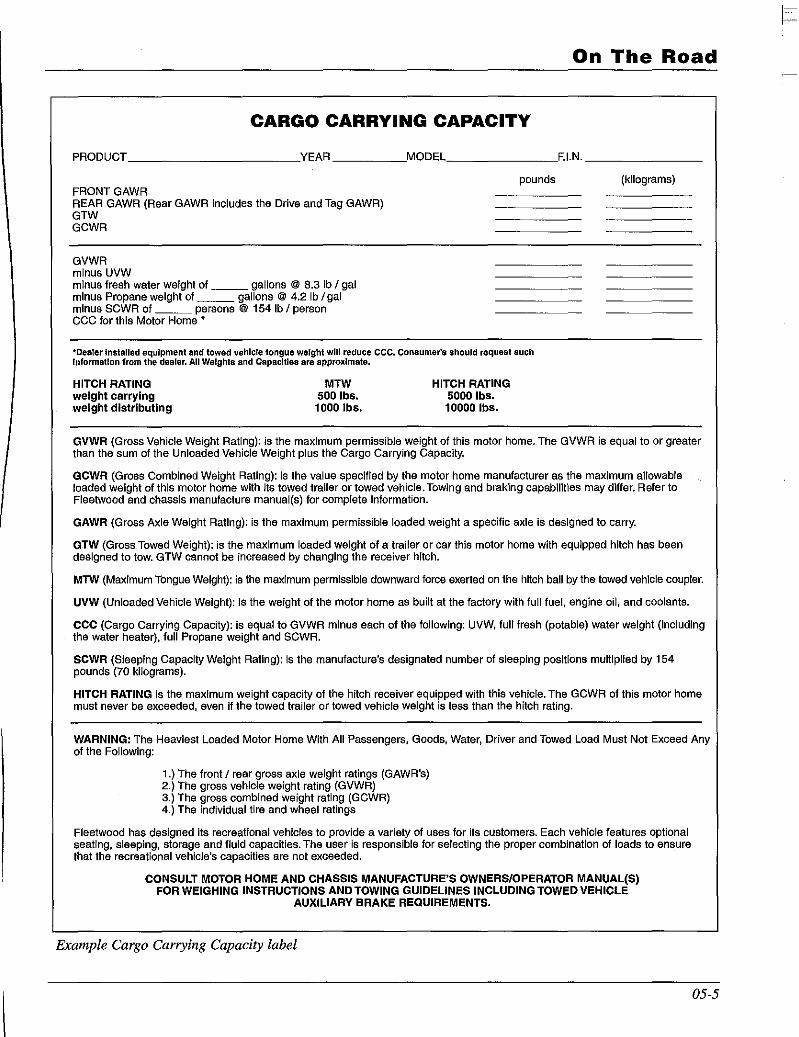
CARGO CARRYING CAPACITY
PRODUCT __________ YEAR ____ MODEL _______ F.I.N. ______ _
FRONTGAWR REAR GAWR (Rear GAWR includes the Drive and Tag GAWR) GTW GCWR
GVWR minus UVW minus fresh water weight of ___ gallons @ 8.3 Ib I gal minus Propane weight of ___ gallons @ 4.2 Ib / gal minus SCWR of ___ persons @ 154 Ib I person CCC for this Motor Home'
pounds
·Dealer Installed equipment and towed vehicle tongue weight will reduce eec. Consumer's should request such Information from the dealer. All Weights and Capacities are approximate.
HITCH RATING weight carrying weight distributing
MTW 5001bs. 10001bs.
HITCH RATING 50001bs. 100001bs.
(kilograms)
GVWR (Gross Vehicle Weight Rating): is the maximum permissible weight of this motor home. The GVWR is equal to or greater than the sum of the Unloaded Vehicle Weight plus the Cargo Carrying Capacity.
GCWR (Gross Combined Weight Rating): is the value specified by the motor home manufacturer as the maximum allowable loaded weight of this motor home with its towed trailer or towed vehicle. Towing and braking capabilities may differ. Refer to Fleetwood and chassis manufacture manual(s) for complete information.
GAWR (Gross Axle Weight Rating): is the maximum permissible loaded weight a specific axle is desIgned to carry.
GTW (Gross Towed Weight): is the maximum loaded weight of a trailer or car this motor home wIth equipped hitch has been designed to tow. GTW cannot be increased by changing the receiver hitch.
MTW (Maximum Tongue Weight): Is the maximum permissible downward force exerted on the hitch ball by the towed vehicle coupler.
UVW (Unloaded Vehicle Weight): is the weight of the motor home as built at the factory with full fuel, engine oil, and coolants.
CCC (Cargo Carrying Capacity): is equal to GVWR minus each of the following: UVW, full fresh (potable) water weight (including the water heater), full Propane weight and SCWR.
SCWR (Sleeping Capacity Weight Rating): is the manufacture's designated number of sleeping positions multiplied by t 54 pounds (70 kilograms).
HITCH RATING is the maximum weight capacity of the hitch receiver equipped with this vehicle. The GCWR of this motor home must never be exceeded, even if the towed trailer or towed vehicle weight is less than the hitch rating.
WARNING: The Heaviest Loaded Motor Home With All Passengers, Goods, Water, Driver and Towed Load Must Not Exceed Any of the Following:
,.) The front / rear gross axle weight ratings (GAWR's) 2.) The gross vehicle weight rating (GVWR) 3.) The gross combined weight rating (GCWR) 4.) The individual tire and wheel ratings
Fleetwood has designed its recreational vehicles to provide a variety of uses for its customers. Each vehicle features optional seating, sleeping, storage and fluid capacities. The user is responsible for selecting the proper combination of loads to ensure that the recreational vehicle's capacities are not exceeded.
CONSULT MOTOR HOME AND CHASSIS MANUFACTURE'S OWNERS/OPERATOR MANUAL(S) FOR WEIGHING INSTRUCTIONS AND TOWING GUIDELINES INCLUDING TOWED VEHICLE
AUXtLIARY BRAKE REQUIREMENTS.
Example Cargo Carrying Capacity label
05-5
On The Road
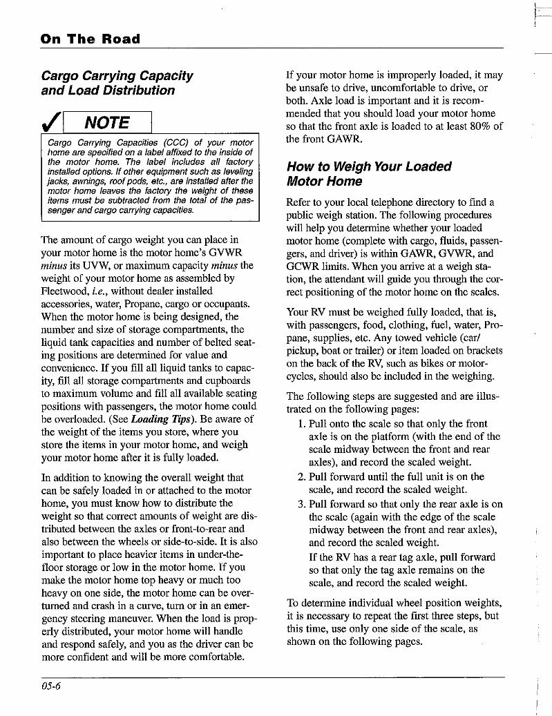
Cargo Carrying Capacity and Load Distribution
.,,1 NOTE 1
Cargo Carrying Capacities (CCC) of your motor home are specified on a label affixed to the inside of the motor home. The label includes all factory installed options. If other equipment such as leveling jacks, awnings, roof pods, etc., are installed after the motor home leaves the factory the weight of these items must be subtracted from the total of the passenger and cargo carrying capacities.
The amount of cargo weight you can place in your motor home is the motor home's GVWR minus its UVW, or maximum capacity minus the weight of your motor home as assembled by Fleetwood, i.e., without dealer installed accessories, water, Propane, cargo or occupants. When the motor home is being designed, the number and size of storage compartments, the liquid tank capacities and number of belted seating positions are determined for value and convenience. If you fill all liquid tanks to capacity, fill all storage compartments and cupboards to maximum volume and fill all available seating positions with passengers, the motor home could be overloaded. (See Loading Tips). Be aware of the weight of the items you store, where you store the items in your motor home, and weigh your motor home after it is fully loaded.
In addition to knowing the overall weight that can be safely loaded in or attached to the motor home, you must know how to distribute the weight so that correct amounts of weight are distributed between the axles or front-to-rear and also between the wheels or side-to-side. It is also important to place heavier items in under-thefloor storage or low in the motor home. If you make the motor home top heavy or much too heavy on one side, the motor home can be overturned and crash in a curve, turn or in an emergency steering maneuver. When the load is properly distributed, your motor home will handle and respond safely, and you as the driver can be more confident and will be more comfortable.
05-6
If your motor home is improperly loaded, it may be unsafe to drive, uncomfortable to drive, or both. Axle load is important and it is recommended that you should load your motor home so that the front axle is loaded to at least 80% of the front GAWR.
How to Weigh Your Loaded Motor Home
Refer to your local telephone directory to find a public weigh station. The following procedures will help you determine whether your loaded motor home (complete with cargo, fluids, passengers, and driver) is within GAWR, GVWR, and GCWR limits. When you arrive at a weigh station, the attendant will guide you through the correct positioning of the motor home on the scales.
Your RV must be weighed fully loaded, that is, with passengers, food, clothing, fuel, water, Propane, supplies, etc. Any towed vehicle (carl pickUp, boat or trailer) or item loaded on brackets on the back of the RV, such as bikes or motorcycles, should also be included in the weighing.
The following steps are suggested and are illustrated on the following pages:
1. Pull onto the scale so that only the front axle is on the platform (with the end of the scale midway between the front and rear axles), and record the scaled weight.
2. Pull forward until the full unit is on the scale, and record the scaled weight.
3. Pull forward so that only the rear axle is on the scale (again with the edge of the scale midway between the front and rear axles), and record the scaled weight.
If the RV has a rear tag axle, pull forward so that only the tag axle remains on the scale, and record the scaled weight.
To determine individual wheel position weights, it is necessary to repeat the first three steps, but this time, use only one side of the scale, as shown on the following pages.
I~= i
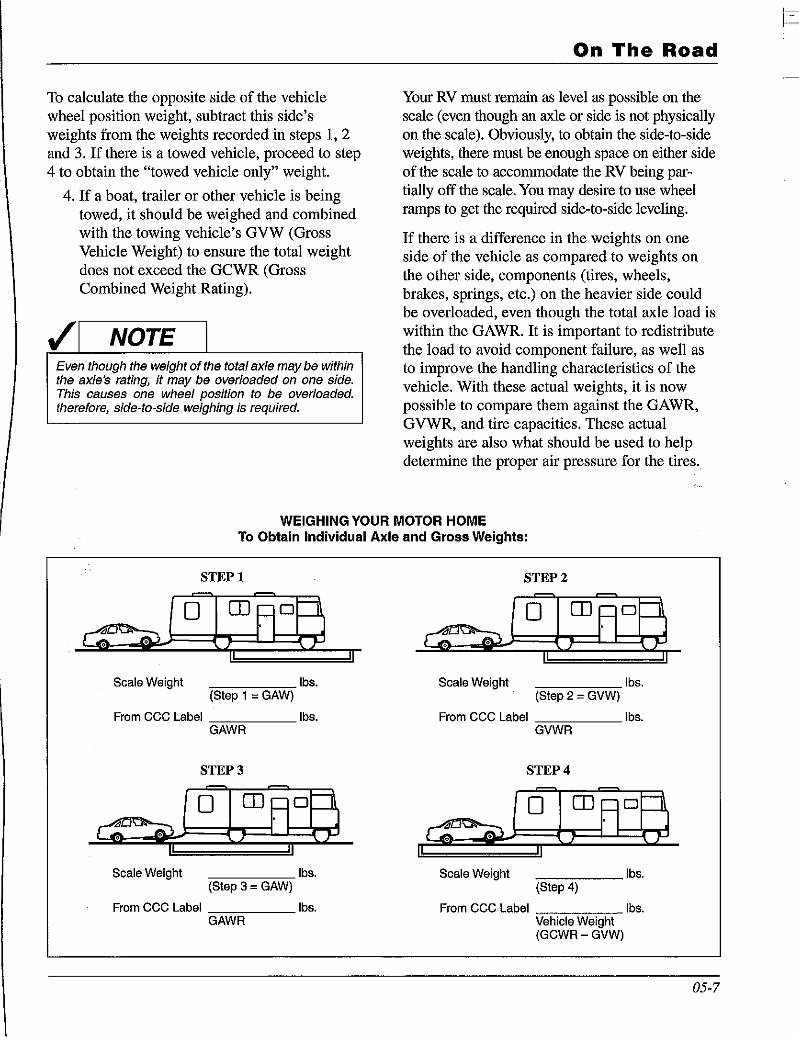
To calculate the opposite side of the vehicle wheel position weight, subtract this side's weights from the weights recorded in steps 1, 2 and 3. If there is a towed vehicle, proceed to step 4 to obtain the "towed vehicle only" weight.
4. If a boat, trailer or other vehicle is being towed, it should be weighed and combined with the towing vehicle's GVW (Gross Vehicle Weight) to ensure the total weight does not exceed the GCWR (Gross Combined Weight Rating).
.II NOTE I Even though the weight of the total axle may be within the axle's rating, it may be overloaded on one side. This causes one wheel position to be overloaded. therefore, side-to-side weighing is required.
On The Road
Your RV must remain as level as possible on the scale (even though an axle or side is not physically on the scale). Obviously, to obtain the side-to-side weights, there must be enough space on either side of the scale to accommodate the RV being partially off the scale. You may desire to use wheel ramps to get the required side-to-side leveling.
If there is a difference in the weights on one side of the vehicle as compared to weights on the other side, components (tires, wheels, brakes, springs, etc.) on the heavier side could be overloaded, even though the total axle load is within the GAWR. It is important to redistribute the load to avoid component failure, as well as to improve the handling characteristics of the vehicle. With these actual weights, it is now possible to compare them against the GAWR, GVWR, and tire capacities. These actual weights are also what should be used to help determine the proper air pressure for the tires.
WEIGHING YOUR MOTOR HOME To Obtain Individual Axle and Gross Weights:
Scale Weight
STEP!
=_;-=;-;-;;-Ibs. (Step 1 _ GAW)
From eee Label ==,----__ Ibs. GAWR
Scale Weight
STEP 3
=_:---=-o."..,--Ibs. (Step 3 = GAW)
From eee Label ==,----__ Ibs. GAWR
II
II
Scale Weight
STEP 2
=-----,:-=;;-:-;;-Ibs. (Step 2 = GVW)
From eee Label ==,----__ Ibs. GVWR
STEP 4
l 0 bCD~D§ iffi II
Scale Weight Ibs. (Step 4)
From eee Label Ibs. Vehicle Weight (GeWR-GVW)
05-7
On The Road
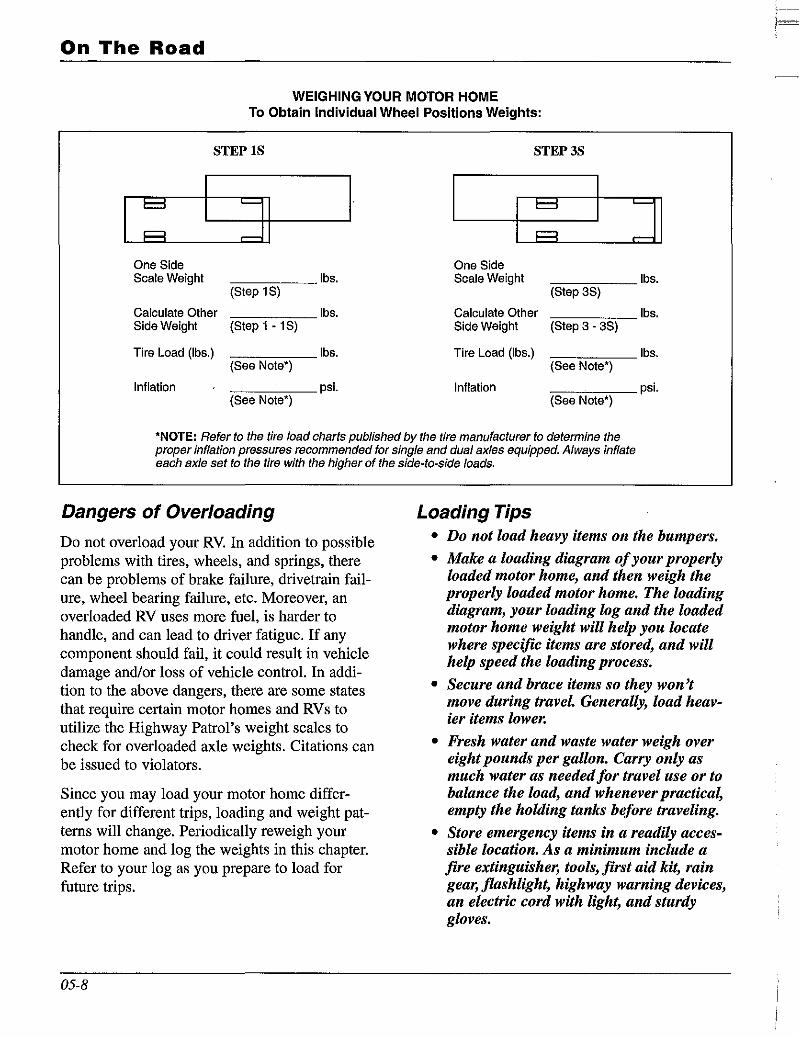
WEIGHING YOUR MOTOR HOME To Obtain Individual Wheel Positions Weights:
STEP IS STEP3S
1 : 1 31
1 1 : 1 JI
One Side One Side Scale Weight Ibs. Scale Weight Ibs.
(Step 1S) (Step 3S)
Calculate Other Ibs. Calculate Other Ibs. Side Weight (Step 1 - 1S) Side Weight (Step 3 - 3S)
Tire Load (Ibs.) Ibs. Tire Load (Ibs.) Ibs. (See Note') (See Note')
Inflation psi. Inflation psi. (See Note') (See Note')
'NOTE: Refer to the tire load charts published by the tire manufacturer to determine the proper inflation pressures recommended for single and dual axles equipped. Always inflate each axle set to the tire with the higher of the side-to-side loads.
Dangers of Overloading
Do not overload your RV. In addition to possible problems with tires, wheels, and springs, there can be problems of brake failure, drivetrain failure, wheel bearing failure, etc. Moreover, an overloaded RV uses more fuel, is harder to handle, and can lead to driver fatigue. If any component should fail, it could result in vehicle damage and/or loss of vehicle control. In addition to the above dangers, there are some states that require certain motor homes and RVs to utilize the Highway Patrol's weight scales to check for overloaded axle weights. Citations can be issued to violators.
Since you may load your motor home differently for different trips, loading and weight patterns will change. Periodically reweigh your motor home and log the weights in this chapter. Refer to your log as you prepare to load for future trips.
05-8
Loading Tips • Do not load heavy items on the bumpers.
• Make a loading diagram of your properly loaded motor home, and then weigh the properly loaded motor home. The loading diagram, your loading log and the loaded motor home weight will help you locate where specific items are stored, and will help speed the loading process.
• Secure and brace items so they won't move during travel. Generally, load heavier items lower.
• Fresh water and waste water weigh over eight pounds per gallon. Carry only as much water as needed for travel use or to balance the load, and whenever practical, empty the holding tanks before traveling.
• Store emergency items in a readily accessible location. As a minimum include a fire extinguisher, tools, first aid kit, rain gear, flashlight, highway warning devices, an electric cord with light, and sturdy gloves.
A CAUTION Modification of your vehicle by addition of racks not originally equipped by the manufacturer to carry additional equipment, vehicles or cargo will reduce your warranty coverage and may cause personal injury or property damage.
A WARNING Do not store or carry Propane containers, gasoline, or other flammable liquids inside your motor home.
TIRES
Your motor home is equipped with wheels and tires selected to match the capacity specifications of the chassis as designed by the chassis manufacturer. Under normal circumstances and with proper tire and chassis maintenance, you should receive thousands of miles of troublefree service.
Some motor homes accumulate relatively few miles and therefore the tire age from the date of manufacture, not mileage, may become the main tire life determining factor. Motor home tires normally have a life of 5-7 years, depending on mileage. However, Fleetwood recommends periodic tire inspection by a reputable tire dealer regardless of tread depth.
.1'1 NOTE 1
When parking your motor home for an extended time, in storage or camping, you can extend tire life by parking each tire on a piece of plywood approximately 12 inches square.
Tire Inflation
For safety and maximum tire life, vehicle speeds must be proper, proper inflation pressure must be maintained, and tread depth and wear must be monitored. Properly inflated and maintained tires also contribute to overall motor home stability and safety. Refer to the tire section in your Chassis Operator's/Owner's Guide/Manual or any tire manufacturer's information that may be provided
On The Road
in your Owners' Information Package for information on maintenance and tire care. If no information is provided please contact your local tire manufacturer's location for advice.
The maximum cold inflation pressures are stated on the tire.sidewall. The recommended maximum tire inflation pressure for this coach is shown on the Federal Certification Tag located on the sidewall near the driver's seat. To maximize tire performance, consult with the tire manufacturer's guidelines or Chassis Operator's/Owner's Guide/Manual for recommended tire inflation pressure.
.1'1 NOTE 1 The tire pressures on your motor home were adjusted at the factory to the tire pressures specified on the Federal certification tag. These pressures are specified at full gross vehicle weight and should be reset to match the weight of your motor home. For maximum performance, tire manufacturers. provide tire inflation pressure charts so you can match the tire pressures to the loads on your motor home. For additional tire pressure information, consult the Chassis Operator's/Owner's Guide/Manual.
A WARNING For safety and maximum tire life, check and adjust tire pressure (including the spare, if equipped) at the beginning of each trip and daily during the trip. Pay special attention to inside rear duals. Always check pressure when tires are cold, and do not bleed air out of warm tires. Follow the tire pressure instructions in the Chassis Operator's/Owner's GuidelManual or the tire manufacturer's tire pressure chart.
.1'1 NOTE 1
Fleetwood recommends using a high quality tire pressure gauge for accurate, repeatable pressure readings.
.1'1 NOTE 1
Check the wheel lug nut tightness periodically. They could work loose during driving. Check the Chassis Operator'slOwner's Guide/Manual for correct lug nut torque and torquing procedure, and schedule.
05-9
On The Road
Air Pressure
The most important factor in maximizing the life of your tires is maintaining proper inflation. Driving on a tire that does not have the correct inflation pressure for the load of the vehicle is dangerous and may cause premature wear, tire damage, and/or loss of control of the vehicle.
A tire that is underinflated will build up excessive heat that may go beyond the prescribed limits of endurance of the rubber and the radial cords. This could result in sudden tire failure. A tire that is underinflated could also cause poor vehicle handling, rapid and/or irregular tire wear, or an increase in rolling resistance which results in a decrease in its fuel economy.
Overinflation will reduce the tire's footprint or contact patch with the road, thus reducing the traction, braking capacity, and handling of the vehicle. A tire that is overinflated for the load that it is carrying will also contribute to a harsh ride, uneven tire wear, and will be more susceptible to impact damage.
Maintaining correct tire inflation pressure for each loaded wheel position on your vehicle is of the utmost importance and must be a part of regular vehicle maintenance.
Federal law requires that the tire's maximum load rating be molded into the sidewall of the tire. If you look on your tire's sidewall you'll see the maximum load allowed for the size tire and load rating, and the minimum cold air inflation pressure needed to carry that stated maximum load. Utilizing less air pressure means a lesser load can be carried by the tire.
The amount of air pressure you need to use depends on the weight of your fully-loaded vehicle. So, you cannot determine your correct air pressure unless you know your vehicle's actual weights.
Underinflation
When an underinflated tire is run at normal highway speeds, it flexes too much and builds up
05-10
heat. This heat damages the inner liner, casing and outer sidewall of the tire. If not remedied quickly, the tire will be irreparably damaged.
In extreme cases, the sidewall of the tire is destroyed, both from the excessive heat it endured and due to the weight of the vehicle pressing on the tire casing without the cushioning effect of the correct air pressure, and the crushing/cutting action of the wheel as it rolls on the underinflated sidewall. According to guidelines put out by the Rubber Manufacturers Association (RMA), any tire that has been run at less than 80% of recommended air pressure for the load it is carrying should be inspected for possible damage.
When one tire in a dual configuration comes out of service due to underinflation damage, the other tire in the dual configuration should be inspected immediately. If the unserviceable tire was underinflated, that means the serviceable tire was carrying more and more of the load for that wheel position. Consequently, it too may have suffered some casing damage.
Air Pressure Check
You should check the air pressure every two weeks or at least once each month and before any major trip. Your RV tires' air pressure should be checked every "drive" morning on long trips. On short trips of a day or less driving each way, your tires should be checked before you leave on your trip and again before you start your trip home.
Check your tires when they are "cold" and have not been driven for more than one mile. The stated load capacity for a given cold inflation pressure is based on ambient outside temperature. If you must check your tires when they are warm or hot, do allow for a slight increase in air pressure and make sure they are within a couple of pounds of each other on the same axle.
Frequently check tires. If a tire picks up a nail or screw that creates a slow leak and causes some air pressure loss, you might eventually spot it visually if it is a front tire. If it is an outside rear
dual, you might also spot it with a visual inspection. However, if it is an inside rear dual, the chances of spotting it without an air pressure check are very slim. If you begin driving without finding it, very quickly (in most cases a few miles) your outside rear tire next to the low air pressure tire is going to heat up from carrying double its load, which will cause both tires to fail.
Tire Replacement
Replacement tires must be the same size, type and tread depth per axle, and have at least the same weight carrying capacity as the original equipment. Tires supplied by various manufacturers of the same size and rating may not have the same weight carrying capacity and maximum cold inflation pressures. Consult your tire dealer. The original equipment wheels and tires supplied on your motor home have weight carrying' capacities to support Gross Axle Weight Ratings (GAWR) as stated on the Federal Certification Tag attached in the driver's compartment.
If You Get a Flat Tire
In case of sudden tire failure:
v'1 NOTE J The motor home will tend to "pull" toward the side with the flat tire.
• Apply the accelerator to maintain directional stability, then gradually release the accelerator.
• Use moderate brake pedal pressure. Do not pump the brake. The vehicle is equipped with Anti-lock Brakes (ABS) which will help control braking.
• Firmly hold the steering wheel while avoiding abrupt steering inputs and move slowly to a safe place.
• Park on a firm level surface.
• Turn off the ignition. • Set the parking brake.
On The Road
• Turn on the hazard flasher system.
• Ensure your passengers are safely located and children monitored.
• Get professional roadside assistance.
Changing a Flat Tire
Even with good tire maintenance and normal driving, you may experience a flat tire. Summon professional help through your auto club, travel service, or a local truck service facility. Your motor home is not equipped with a jack or other lifting device. Do not attempt to lift the motor home with a jack. Consult the Chassis Operator's/Owner's Guide! Manual for additional information on tire inflation and proper torque.
A CAUTION Wheels and tires equipped with your motor home are extremely heavy and may weigh 100 pounds or more. Do not attempt to remove the spare tire (if equipped) unless you are capable of handling the weight.
A WARNING To avoid personal injury and/or property damage if a blowout or other tire damage occurs, obtain expert tire service help. Do not attempt to change the tire yourself.
SEATS AND SEAT BELTS
Seat belts help to restrain you and your passengers in case of a collision. In most states, the law requires their use.
Seat belts provide the best restraint when:
• the seat back is upright
• the occupant is sitting upright (not slouching)
• the lap belt is snug and low on the hips
• the shoulder belt is snug against the chest
• the knees are straight forward
05-11
On The Road
A WARNING Make sure that you and your passengers, including pregnant women, wear safety belts. Be sure that lap belts fit snugly and as low as possible around the hips. If safety belts are not used properly, the risk of you or your passengers being injured in a collision greatly Increases.
For your safety, your vehicle has combination lap and shoulder belts for the driver and front seat passenger and lap belts without retractors in all other designated seating positions.
Always drive and ride with your seatback upright and the lap belt snug and low across the hips to reduce the risk of serious injury to the abdomen or neck that could be caused by sliding under the safety belts in a collision.
Never let a passenger hold a child on his or her lap while the vehicle is moving. The passenger cannot protect the child from injury in a collision. Refer to sections on Safety Restraints for Children and Safety Belts for Children.
Never use a single belt for more than one person or across more than one seating position. This greatly increases the risk that one or both of the people will be injured in a collision. Each designated seating position in your vehicle has a specific seat belt assembly which is made up of one buckle and one tongue that are designed to be used as a pair.
AIR BAGS (If Equipped) Air Bag Supplemental Restraint System (SRS)
If your RV is equipped with Air Bag Supplemental Restraint System (SRS), please refer to your Chassis Operator's/Owner's Guide/ Manual for any instructions supplied by the chassis manufacturer with respect to this system.
Combination Lap and Shoulder Belts
While your vehicle is in motion, the combination lap and shoulder belt adjusts to your movement.
05-12
However, if you brake hard, comer hard or if your vehicle receives an impact, the lap and shoulder belt locks and prevents you from moving.
A WARNING Use the shoulder belt on the outside shoulder only. Never wear the shoulder belt under the arm. Never swing it around the neck over the inside shoulder. Failure to follow these precautions could increase the risk and/or severity of injury in an accident.
To fasten the belt, pull the lap/shoulder belt from the extractor so that the shoulder portion of the belt crosses your shoulder and chest. Insert the belt tongue into the proper buckle until you hear a snap and feel it latch. (For more details on Seat Belt usage, see Manufacturer's Usage Manual.)
To tighten the lap portion of the belt, pull up on the shoulder belt until it fits you snugly. The belt should rest as low on your hips as possible.
A longer lap and shoulder belt assembly is available and is a direct replacement for the driver and front passenger positions. The longer lap and shoulder belt is made and tested to the same standards as the original belt. This belt assembly can be purchased and installed at any authorized Fleetwood motor home dealer.
Safety Belt Maintenance
Check your safety belt system periodically to make sure that it works properly and isn't damaged. If the webbing shows any wear, nicks or cuts, have it examined by a qualified technician to determine if replacement is necessary. Always have your safety belt system checked after a collision.
Safety Restraints for Children
In most states, you are required by law to use safety restraints for children. If small children ride in your vehicle, you must put them in safety seats that are made specially for children. Safety belts alone do not provide maximum protection for these children. Check your local and state laws for specific requirements.
Safety belts and seats can become hot in a vehicle that has been closed up in sunny weather, and could bum a child. Check seat covers and buckles before you place a child anywhere near them.
Children who are too large for child safety seats should always wear safety belts.
A. WARNING Never leave a child unattended in your vehicle. Always remove the key from the ignition and take it with you.
Safety Belts for Children
If the shoulder belt cannot be properly positioned so that it does not cross or rest in front of the child's face or neck, move the child to one of the seats with a lap belt only and use the lap belt.
Lap belts and the lap portion of lap and shoulder belts should always be worn snugly and below the hips, touching the child's thighs.
Children should use forward or rearward facing seat positions, not seated facing sideways.
A. WARNING If safety belts are not properly worn and adjusted as described, the risk of serious injury to the child in a collision will be much greater.
Children should always ride with the seatback in the fully upright position. When the seatback is not fully upright, there is a greater risk that the child will slide under the safety belt and be seriously injured in a collision.
Use a safety seat that is recommended for the size and weight of the child. Seat backs should be upright for use with child safety seats. Any objects in close proximity which may come into contact with the child in the event of an accident or sudden stop should be removed.
A. WARNING Place child safety seats only in forward facing (locked) seating positions equipped with a restraint system.
On The Road
A. WARNING Carefully follow all of the manufacture~s instructions that come with the safety seat that you put in your vehi-cle. Make sure that the shoulder belt (if provided at the seating position where the safety seat is being used) does not cross or rest in front of the child's face or neck. If you do not install and use the safety seat properly, the child may be injured in a sudden stop or collision.
A. WARNING When using any infant or child restraint system, it is important that you follow the instructions and warn-ings provided by the manufacturer concerning its installation and use. Failure to follow the restraint manufacturer's instructions could increase the risk or severity of an injury in the event of a collision or sudden stop.
Child Seat Tethers
Some child seat manufacturers recommend the use of a top anchorage (tether) strap in addition to the lap belt. Since a top anchorage (tether) strap can provide additional security to a child seat, we recommend using a tether whenever one is required or available.
Your motor home is equipped with a child seat top anchorage (tether) strap anchorage point in the forward passenger seat location. In some models a secondary forward facing seat location may also have the anchorage for a tether strap.
You can visually identify the anchorage hardware by inspecting the lower rear of the passenger or secondary seat. A small metal anchorage rod will be present which will allow the tether strap hook to engage (see Illustration 1).
To use, with the seat in position, drape the tether strap over the seat back and down (see Illustration 2). Attach the tether strap hook to the tether anchorage point and tighten the strap according to the child seat manufacturers instructions. Make sure the strap is not twisted and that the forward facing seat is always positioned upright and locked in the forward facing position when the motor home is in motion.
05-13
1-1=
On The Road
A WARNING An incorrectly anchored tether strap could lead to seat failure and injury to the child. In a collision, the seat could come loose and allow the child to crash into the inside of the vehicle or other passengers, or eveh be thrown from the vehicle. Use only the specified anchor positions to secure a child restraint requiring top tether strap(s).
Illustration 1
Illustration 2
05-14
DRIVING AND VEHICLE CONTROL
Driving your motor home will be different from driving your family car or truck. Your motor home is large and heavy. You may have to adjust or learn new driving techniques to safely operate your motor home.
Downhill driving puts extra strain on many drivetrain components of your motor home. The brakes are easily overloaded and overheated when used for downhill slowing. Brake fade will occur if the brakes overheat.
When driving down long grades, shift the transmission to a lower gear at the top of the grade. Rule of thumb: Use the same lowest gear going down as it took to go up the hill. Crest the hill in the lower gear. Monitor your speed.
Using the Engine to Slow the Motor Home
To use the engine as a braking force, select the next lower gear. Engine braking provides good speed control for going down grades. When the motor home is heavily loaded, or the grade is steep, preselection of a lower gear prior to the grade may be desirable.
Gear preselection means the selection of a lower gear to match the driving conditions you encounter or expect to encounter. Preselection will give you better control on slick or icy roads and on downgrades. Downshifting to lower gears increases engine braking. The selection of a lower gear often prevents cycling between a gear and the next higher gear on a series of short up-and-down hills.
MANEUVERING IN TRAFFIC
Be cautious when maneuvering to allow for the length and width of the vehicle. Always allow room to comer and to change lanes. Your vehicle's side view mirrors and rear view camera monitor (if equipped) will help you keep aware of your vehicle's position and the position of other vehicles
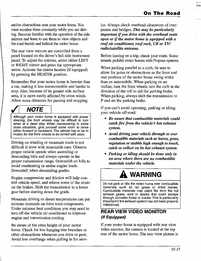
andlor obstructions near your motor home. You must monitor them constantly while you are driving. Become familiar with the operation of the side mirrors and learn to use them to view objects and the road beside and behind the motor home.
The rear view mirrors are controlled from a panel located on the driver's left side instrument panel. To adjust the mirrors, select either LEFr or RIGHT mirror and press the appropriate arrow. Activate the mirror heaters (if equipped) by pressing the HEATER position.
Remember that your motor home is heavier than a car, making it less maneuverable and harder to stop. Also, because of its greater side surface area, it is more easily affected by cross winds. Allow extra distances for passing and stopping.
~I NOTE I Although your motor home is equipped with power steering, the front wheels may be difficult to turn when at a dead stop. When maneuvering in some close situations, give yourself some room to move either forward or backward. The vehicle has to be in motion for the front wheels to be turned with ease.
Driving on winding or mountain roads is not difficult if done with reasonable care. Observe proper vehicle speeds when ascending or descending hills and always operate in the proper transmission range. Downshift on hills to avoid overheating or undue engine loads. Downshift when descending grades.
Engine compression and friction will help control vehicle speed, and relieve some of the strain on the brakes. Shift the transmission to a lower gear before starting down the grade.
Mountain driving or desert temperatures can put extreme demands on drive train components. Under extreme heat conditions you may need to tum off the vehicle air conditioner to improve engine and transmission cooling.
Be aware of the extra height of your motor home. Check for low hanging tree branches or other obstructions whenever you drive or park. Avoid low overhangs when pulling in for serv-
On The Road
ice. Always check overhead clearances of overpasses and bridges. This may be particularly important if you drive with the overhead vents open or if the motor home is equipped with a roof air conditioner, roof rack, CB or TV! radio/satellite antenna.
Before leaving on a trip, check your route. Some tunnels prohibit motor homes with Propane systems.
When parking parallel to a curb, be sure to allow for poles or obstructions as the front and rear portions of the motor home swing wider than an automobile. When parking on an incline, tum the front wheels into the curb in the direction of the roll to aid the parking brake. When parking, always shift the transmission to P and set the parking brake.
If you can't avoid operating, parking or idling your vehicle off-road:
• Be aware that combustible materials could catch fire from the vehicle's hot exhaust system.
• Avoid driving your vehicle through or over combustible materials such as leaves, grass, vegetation or stubble high enough to touch, catch or collect on its hot exhaust system.
• Parking or idling should be done only in an area where there are no combustible materials under the vehicle.
A WARNING Do not park or idle the motor home over combustible materials such as tall grass or dried leaves. Combustible materials may catch fire from the hot exhaust gases, soot or sparks that could escape through corrosion holes or cracks. This is particularly important if the exhaust system has not been properly maintained.
REAR VIEW VIDEO MONITOR (If Equipped)
If your motor home is equipped with rear view video monitor, the camera is located at the top rear of the motor home. The rear view picture is
05-15
On The Road
displayed on a screen in the driver's compartment. The monitor screen may be overlaid with a distance scale reference which gives approximate distance of objects to the rear of the motor home.
The rear view video monitor works in two modes:
Mode 1 - Standby (Indicator will be lit to green)
1. Turn on the ignition switch.
2. Shift the transmission to [Rleverse.
3. Monitor on.
Mode 2 - On (Indicator will be lit to amber)
1. Turn on the ignition switch.
2. Monitor on.
Using the rear view video monitor will take practice. Always allow more space for maneuvering until you are comfortable with the system. Check the side-mounted mirrors often while driving and especially during lane changes and when backing up.
CAUTION The rear view video monitor system provides a general view of the road and objects to the rear of the motor home. Your perception of this view and the relationships of objects to the motor home and each other will be different from that seen in a rear view mirror. Light conditions and the adjustment of the screen controls will also affect your perception. Always use the side-mounted rear view mirrors with the video monitor system.
The camera lens is exposed to road dirt and will get dirty. When necessary, clean the camera lens and monitor screen with a quality glass cleaner and nonabrasive cloth or towel.
BODY UNDERCOATING
Certain chassis and underbody components of your motor home have been coated with an undercoating material. This material is intended to assist in protecting these components from corrosion or other effects of weather and road conditions. Please be aware that certain areas of
05-16
the motor home do not have undercoating applied, in keeping with good engineering practice, and to meet the requirements of chassis manufacturers.
FUEL AND FUEL SYSTEMS See the Chassis Operator's/Owner's Guide/Manual in the Owner's Information Package for chassis engine fuel recommendations. The standard generator is designed to run on the same fuel as the chassis engine, or on Propane. Consult the generator operating instructions for special cautions about maintenance with different types of fuels.
Modern fuel systems may build up vapor pressure within the tank as the fuel warms during use or hot weather. Under certain conditions, sudden release of this pressure when removing the fuel cap can cause fuel to spray from the fill opening, creating a fire hazard.
A WARNING When removing the fuel fill cap, rotate it slowly only far enough to allow the pressure to release. After any "hissing" sound stops, remove the cap completely.
To protect the fuel system from excessive pressure or vacuum, or from sudden release of pressure, replace lost or damaged fuel fill caps with caps of the same design which are available from your Fleetwood motor home dealer.
Clean up fuel spills immediately. Fuel spilled on the motor home could damage the exterior finish, and is a serious fire hazard.
Safe Refueling Guidelines
Here are some refueling safety guidelines that will help keep you and your family safe when refueling your vehicle.
• Turn off your vehicle engine while refueling. Put your vehicle in park and/or set the emergency brake. Disable or turn off any auxiliary sources of ignition such as heater, cooking units or pilot lights.
'--- -----. - .
• Do not smoke, light matches or lighters while refueling at the pump or when using gasoline anywhere else.
• Use only the refueling latch provided on the gasoline dispenser nozzle - never jam the refueling latch on the nozzle during refueling.
A" WARNING Certain fabrics, clothing and/or shoe apparel may potentially create an electrostatic charge, which may not immediately discharge upon exit of your motor home. During refueling, the static may discharge at the fill point, causing a flash fire or small-sustained fire with gasoline vapors. In order to avoid this from occurring always first touch a metal part of the vehicle with a bare hand, such as the door, or some other metal surface away from the fill point.
• In the unlikely event a static-caused fire occurs when refueling, leave the nozzle in the fill pipe and back away from the vehicle. Notify the station attendant immediately.
• Do not over-fill or top-off your vehicle tank, which can cause gasoline spillage.
• Avoid prolonged breathing of gasoline vapors. Use gasoline only in open areas that get plenty of fresh air. Keep your face away from the nozzle or container opening.
• Always re-install the fuel cap correctly before departing.
.t'l NOTE J Fuel for the generator is taken from the main fuel tank through a special feeder tube which is higher in the tank than the feeder tube to the motor home engine. This arrangement prevents the generator from running the motor home fuel tank dry.
On The Road
Fuel Types and Driveability Issues
Your motor home's automotive fuel and emissions systems are sophisticated and engineered to meet Federal and State emissions standards. They are sometimes sensitive to fuel types and blends, particularly fuels blended for certain altitudes and climates. Fuel suppliers provide customers with the correct fuel for their location and seasonal conditions. Sometimes, though, fuel blended for winter is supplied during summer months.
API REFUELING ADVISORY
The American Petroleum Institute (API) offers the following consumer advisory and safety guidelines on vehicle refueling to help consumers avoid potential problems with refueling and static electricity.
One of many possible causes of static electricity build-up is reentering your vehicle during refueling, particularly in cool or cold and dry climate conditions. This can cause a build-up of static electricity similar to shuffling your feet on the carpet when the air in your home is dry. If you return from your vehicle interior to remove the filling nozzle without discharging the static build-up, in rare circumstances, a brief flash fire could occur at the filling point if the static discharges and the resulting spark ignites fuel vapors around the fill spout.
A simple precaution to help avoid this potential problem is to stay near the vehicle's fueling point. Do not get back into your vehicle during refueling - even when using the nozzle's automatic hold-open latch. If you must reenter your vehicle, discharge the static electricity build-up when you get out by touching the outside metal portion of your vehicle, away from the filling point, before attempting to remove the nozzle.
05-17
On The Road
ENGINE FAN
When the engine is under load or requires maximum cooling, the engine fan turns faster. The fan may become noisy at high speed and when maximum cooling is required. High speed fan noise can sometimes be misinterpreted as transmission slippage. This is not the case. This fan noise indicates that the fan is doing what it is supposed to do. This noise is not a defect in the fan or the transmission.
EXHAUST SYSTEM HEAT
Your motor home engine has been designed to conform to Federal and State emission requirements. To meet these requirements, engine operating temperatures are high. As a result, the engine, transmission and exhaust systems radiate heat.
Heat shields are built into your motor home to protect wiring and other components from possible heat damage caused by the exhaust system. Do not remove these shields, modify the exhaust system, or add additional equipment, such as wiring, plumbing, or other components, which may be effected by exhaust system heat.
ENGINE TEMPERATURE GAUGES
Engine temperature gauges typically have been calibrated to indicate a midrange reading as the "normal" operating temperature. As a motor home owner, be aware that the gauge is intended to provide a warning of any rapid change in engine coolant temperature from the "normal" reading of the gauge rather than an absolute temperature reading.
CARBON MONOXIDE SAFETY PRECAUTIONS
Carbon monoxide is a colorless, tasteless, odorless gas. It is a by-product of the burning of fossil fuels (gasoline, Propane, diesel fuel, etc.). The chassis
05-18
and generator engines, furnaces, water heater, Propane refrigerator and range in your motor home produce it constantly while they are operating. CARBON MONOXIDE IS DEADLY. Please read and understand the following precautions to protect yourself and others from the effects of carbon monoxide poisoning.
Beware of the symptoms of exhaust gas (carbon monoxide) poisoning:
Dizziness Vomiting Nausea Muscular twitching Intense headache Throbbing in temples Weakness and sleepiness Inability to think clearly
A WARNING Do not under any circumstances operate any engine or the cooking stove or range while sleeping. You would not be able to monitor outsider conditions to assure that engine exhaust does not enter the interior, and you would not be alert to exhaust odors or symptoms of carbon monoxide poisoning.
A WARNING Exhaust gases are deadly. Do not block the tailpipes, or exhaust ports, or situate the vehicle in a place where the exhaust gases have any possibility of accumulating either outside, underneath, or inside your vehicle or any nearby vehicles. Outside air movements can carry exhaust gases inside the vehicle through windows or other openings remote from the exhaust outlet. Operate the engine(s), carbon monoxide-producing systems or components only when safe dispersion of exhaust gases can be assured. Monitor outside conditions to be sure that exhaust continues to be dispersed safely.
If you or others experience any of these symptoms, get out into fresh air immediately. If symptoms persist, seek medical attention. Shut down the unit and do not operate it until it has been inspected and repaired.
f:=-~ I
Carbon Monoxide Detector/Alarm
Your motor home is equipped with a carbon monoxide (CO) detector/alarm.
If the detector/alarm sounds, it is an indication that unacceptable levels of carbon monoxide gas are present. This may occur in traffic concentrations or in campgrounds where other vehicles as well as your motor home are contributing to the carbon monoxide level in the surrounding air. Sounding of the detector/alarm does not indicate a faulty detector/alarm. The detector/alarm is doing its job of warning you of potentially high concentrations of carbon monoxide.
Test the CO detector/alarm after the motor home has been in storage, before each trip, and at least once a week during use. Please refer to the materials included in your Owner's Information Package.
EMERGENCY TOWING
The preferred emergency towing methods are either an under reach wheel lift device or a flat bed trailer. Most tow truck operators willing to tow motor homes will be familiar with these devices. Be prepared to give the tow truck operator at least the following information when you call:
Length and height of motor home Chassis manufacturer Gross vehicle weight rating
CAUTION Do not tow the motor home from the rear. Towing from the rear will cause serious overloading of the front tires and suspension, possibly resulting in tire or front suspension failure. The rear frame extensions are not designed to withstand the load imposed by lifting from the rear.
A WARNING DO NOT crawl under or place any part of your body under a vehicle that is being lifted. Stand clear of all towing equipment and the vehicle being lifted.
On The Road
The vehicle must be towed from the front, either on the rear wheels (if operational) or on a heavy duty dolly. Consult your Chassis Operator's/ Owner's Guide/Manual for any available instructions. Contact the chassis assistance center prior to calling a tow company to receive tow instructions and possible assistance with coordinating the tow.
To prepare your motor home for towing:
1. Secure any loose or protruding parts of the disabled vehicle, if any.
2. Secure any heavy, loose items in the interior.
3. Turn off Propane appliances and the Propane tank valve.
4. Do not allow any person to ride in the towed vehicle.
Windshield Wipers & Washers Your motor home is equipped with windshield wipers. It is important to have the proper windshield washer solution to maintain your system in good operating order.
CAUTION Use only a windshield washer solution that is rated for a minimum of -20 degrees F (-8 degrees C) to prevent damage to the system from freezing up.
05-19

<.
1:=:=
This page intentionally blank.
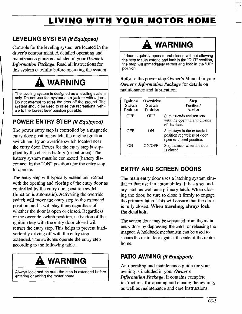
LIVING WITH YOUR MOTOR HOME
LEVELING SYSTEM (If Equipped)
Controls for the leveling system are located in the driver's compartment. A detailed operating and maintenance guide is included in your Owner's Information Package. Read all instructions for this system carefully before operating the system.
A WARNING The leveling system is designed as a leveling system only. Do not use the system as a jack or with a jack. Do not attempt to raise the tires off the ground. The system should be used to raise the recreational vehicle to the lowest level position possible.
POWER ENTRY STEP (If Equipped)
The power entry step is controlled by a magnetic entry door position switch, the engine ignition switch and by an override switch located near the entry door. Power for the entry step is supplied by the chassis battery (or batteries). The battery system must be connected (battery disconnect in the "ON" position) for the entry step to operate.
The entry step will typically extend and retract with the opening and closing of the entry door as controlled by the entry door position switch (function is automatic). Activating the override switch will move the entry step to the extended position, and it will stay there regardless of whether the door is open or closed. Regardless of the override switch position, activation of the ignition key with the entry door closed will retract the entry step. This helps to prevent inadvertently driving off with the entry step extended. The switches operate the entry step according to the following table.
A WARNING Always look and be sure the step is extended before entering or exiting the motor home.
A WARNING If door is quickly opened and closed without allowing the step to fully extend and lock in the "OUT" position, the step will immediately retract and lock in the "UP" position.
Refer to the power step Owner's Manual in your Owner's Information Package for details on maintenance and lubrication.
Ignition Overdrive Step Switch Switch Position!
Position Position Action
OFF OFF Step extends and retracts with the opening and closing of the door.
OFF ON Step stays in the extended position regardless of door open or closed position.
ON ON/OFF Step retracts when the door is closed.
ENTRY AND SCREEN DOORS
The main entry door uses a latching system similar to that used in automobiles. It has a secondary latch as well as a primary latch. When closing the door, be sure to close it firmly to engage the primary latch. This will ensure that the door is fully closed. When traveling, always lock the deadbolt.
The screen door may be separated from the main entry door by depressing the catch or releasing the magnet. A holdback mechanism can be used to secure the main door against the side of the motor home.
PATIO AWNING (If Equipped)
An operating and maintenance guide for your awning is included in your Owner's Information Package. It contains complete instructions for opening and closing the awning, as well as maintenance and care instructions.
06-1
1---
b
Living With Your Motor Home
WINDOWS
Windows in your motor home are either slider or torque pane type. Open slider windows by rotating the locking lever and sliding the window. Open and adjust torque windows by turning the knob or crank located at the bottom of the window frame.
On your ventilating windows, water is trapped by the frame. During a heavy downpour or washing, water may be seen in the lower portion of the frame. The sloping sill and weep slots allow the water to drain to the outside. These weep slots must be kept open.
Damage or failure resulting from misuse, including the application of after-market window tinting, is the owner's responsibility.
If water collects in the bottom channel and overflows, check the weep slots for debris and obstructions and clean as necessary.
~I NOTE J Screens are not removable for cleaning. They may be pushed out of their frames if the window must be used for emergency exit. In this case, the screens will be destroyed and will probably have to be replaced.
Emergency Exit Window(s)
Emergency exit windows are identified by the red handles and EXIT label. Storm windows should never be installed over emergency exit windows.
Read and understand these instructions before you need to use them. The emergency exit window provides an escape route in case the motor home must be evacuated under emergency conditions. To operate the emergency exit window, either:
• Pull the red handle and remove the screen, or;
• Lift the red latch to release the window. Slide it completely through the slot so the window swings free.
When parked, be sure the exit window is not blocked by trees or other obstacles.
06-2
REMOTE MIRROR CONTROL (If Equipped)
Your new motor home may be equipped with the optional power mirror. The driver's control panel also contains controls for the exterior rear view mirror adjustment and heater, if equipped.
To adjust the mirrors, select either LEFT or RIGHT mirror and press the appropriate arrow. Activate the mirror heaters by pressing the HEATER control.
In the event the power mirror option was not selected and added, manual adjustment of the mirrors is required to provide a view of the sides and rear of the motor home.
SUN VISORS (If Equipped)
Sun visors at the driver and passenger positions swing down and are adjustable to provide relief from glare and bright sun. Your motor home may also be equipped with side shades mounted on the side windows that can be adjusted to suit driving conditions. Swivel tension may be adjusted with a screwdriver at the tension adjusting screw.
PULL SHADES (If Equipped)
To Lower shades: Gently pull the shade down to the desired height.
To Raise shades: Gently pull the bottom of shade until the spring tension from the roller is felt, allowing shade to raise to desired height.
, 'i ___ _ .1---'---
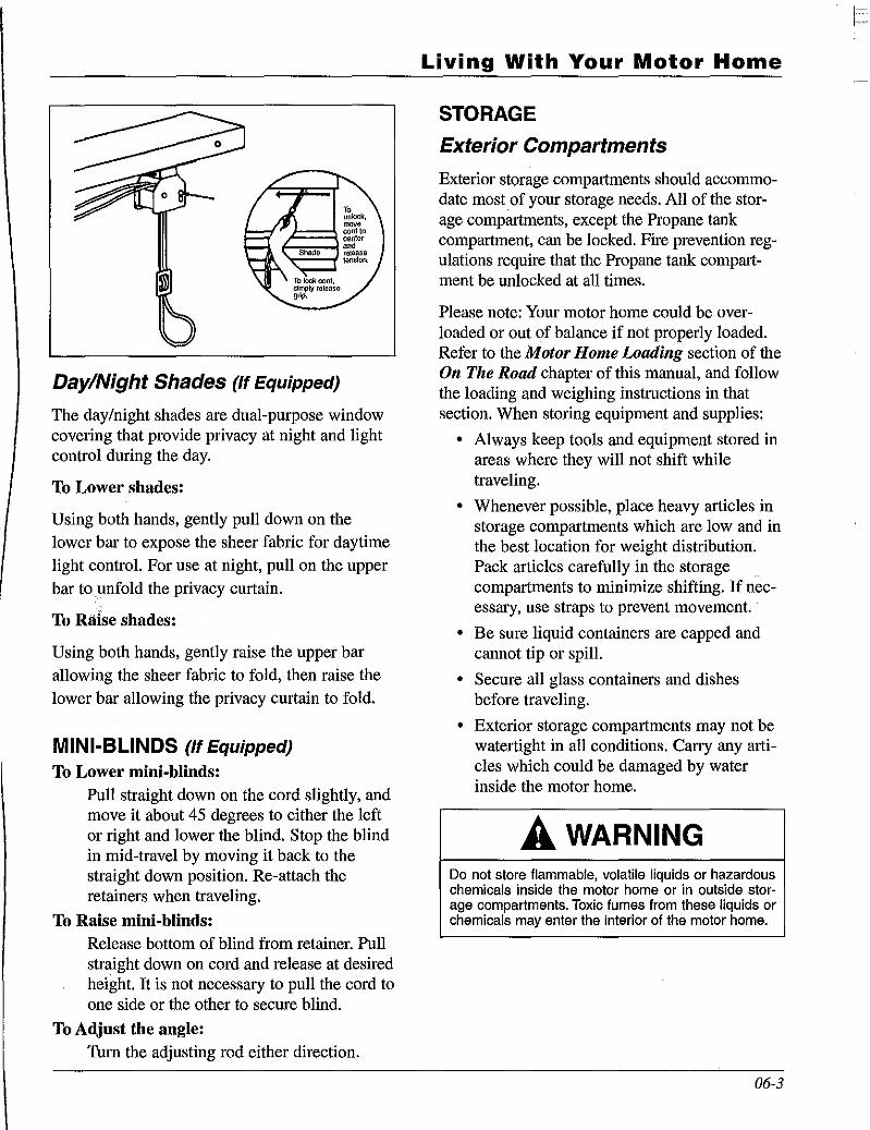
To locI<oord, simply release grip.
Day/Night Shades (If Equipped)
The day/night shades are dual-purpose window covering that provide privacy at night and light control during the day.
To Lower shades:
Using both hands, gently pull down on the lower bar to expose the sheer fabric for daytime light control. For use at night, pull on the upper bar to unfold the privacy curtain.
To Raise shades:
Using both hands, gently raise the upper bar allowing the sheer fabric to fold, then raise the lower bar allowing the privacy curtain to fold.
MINI-BLINDS (If Equipped) To Lower mini-blinds:
Pull straight down on the cord slightly, and move it about 45 degrees to either the left or right and lower the blind. Stop the blind in mid-travel by moving it back to the straight down position. Re-attach the retainers when traveling.
To Raise mini-blinds: Release bottom of blind from retainer. Pull straight down on cord and release at desired height. It is not necessary to pull the cord to one side or the other to secure blind.
To Adjust the angle: Turn the adjusting rod either direction.
Living With Your Motor Home
STORAGE
Exterior Compartments
Exterior storage compartments should accommodate most of your storage needs. All of the storage compartments, except the Propane tank compartment, can be locked. Fire prevention regulations require that the Propane tank compartment be unlocked at all times.
Please note: Your motor home could be overloaded or out of balance if not properly loaded. Refer to the Motor Home Loading section of the On The Road chapter of this manual, and follow the loading and weighing instructions in that section. When storing equipment and supplies:
• Always keep tools and equipment stored in areas where they will not shift while traveling.
• Whenever possible, place heavy articles in storage compartments which are low and in the best location for weight distribution. Pack articles carefully in the storage compartments to minimize shifting. If necessary, use straps to prevent movement.
• Be sure liquid containers are capped and cannot tip or spill.
• Secure all glass containers and dishes before traveling.
• Exterior storage compartments may not be watertight in all conditions. Carry any articles which could be damaged by water inside the motor home.
A WARNING Do not store flammable, volatile liquids or hazardous chemicals inside the motor home or in outside storage compartments. Toxic fumes from these liquids or chemicals may enter the interior of the motor home.
06-3
Living With Your Motor Home
Interior Storage
The closets and cabinets have catches along one edge of the door. Pull on the cabinet door handle to open. Overhead doors have supports to hold them open. Drawers rest in notches when they are closed. To open drawers, lift up slightly, then pull open.
Closets may be equipped with 12-volt lights that turn ON when the closet door is opened. Be sure the light goes OFF when the closet door is closed-your battery will be discharged if it stays ON. If the light stays on when the door is closed, the door switch requires adjustment.
The same loading considerations apply to interior storage areas as to exterior. Consult the Motor Home Loading section in the On The Road chapter.
SLIDE-OUT ROOMS (/f Equipped)
Your new motor home may be equipped with an optional slide-out room. The slide-out room( s) are designed to provide additional living space.
A detailed operating and maintenance guide is included in your Owner's Information Package. Read all instructions for these systems carefully before operating the slide-outs.
In some installations it may be necessary to slide the driver's seat to the full forward position and place the seat back in the full upright position prior to moving the slide-out room in or out to prevent the room from striking or rubbing against the seat back.
Always exercise caution when operating the slide-out room.
• Always be certain that there is plenty of clearance for your room to safely extend to the full outward position.
• Remove any other potential obstructions to room movement.
06-4
For operation of the slide-out room the following is required:
• Park the RV and level it for stationary use. • Ignition on (engine running) • Transmission in park • Parking brake engaged • Slide-out key or switch activated
v'l NOTE I Under wet/snow weather conditions, after retracting the slide-out room(s), it may be necessary to towel off moisture from the end walls.
CAUTION Never attempt to move your motor home with the slide-out room(s) extended. Damage can occur to the slide-out or motor home.
CAUTION In case of a power failure, the slide-out room can be retracted manually. Be sure to understand the opera-tion section as explained in the slide-out systems Operations Manual in the Owner's Information Package.
INTERIOR AND FURNISHINGS
The materials used inside your motor home have been selected for durability and comfort. With reasonable care, these materials will stand up under years of recreational living. The Maintenance chapter in this manual outlines care requirements for the various upholstery fabrics, floor, cabinet, and wall finishes.
Dinette Conversion (with Built-in Tab/e)
To convert the dinette into a bed:
1. Remove cushions.
2. Lift table, reach underneath, unlatch and fold the leges) up under the table top, or remove the table leges) and if necessary, store them between the seats.
i '~--
3. Raise front portion of table several inches to disengage inserts from the wall supports.
4. Lower table top to the dinette frame to complete the bed base.
5. Slide seat and back cushion into place over the bed base.
The under-seat storage may be reached by raising the cushion platform.
Dinette Conversion (with Free-Standing Table)
To convert the dinette into a bed:
1. Lift table, reach underneath, fold up the legs under the table top. Secure the legs.
2. Lower table top to the dinette frame to complete the bed base.
3. Slide the seat and back cushion into place over the bed base. The under-seat storage may be reached by raising the cushion platform.
SofEi Conversion (If Equipped)
To convert a sofa bed into a bed:
1. Remove sofa bolsters (if applicable).
2. Lift front of sofa seat (above front kick panel) up and out. The back of the sofa will drop back and down as the seat is pulled outward.
To restore the sofa/lounge:
1. Lift the front edge of the sofa seat up, and push it back towards rear. The sofa back will come up.
2. Push the sofa fully into position.
Sleeper Sofa Conversion (If Equipped)
To convert a sleeper sofa into a bed:
1. Remove sofa cushions.
2. Lift front of sofa seat (above front kick panel) up and out. While lifting the seat out, the middle legs will automatically unfold into a vertical position.
Living With Your Motor Home
3. Pull upward on the center of the metal bar, and rotate it down slowly until the wood bars rest on the floor.
To restore the sleeper sofa:
1. Lift the front edge of the bedframe up and rotate it back.
2. Lift the middle section of the bed up and push it back towards the rear until the bed is fully into position.
3. Replace the cushions.
Folding Doors/Privacy Curtain Dividers
The dividers allow you to separate areas in the motor home. They glide on nylon rollers. They are held closed by a catch. When the dividers are open for traveling, be sure to attach the hold back latch to keep them from sliding back and forth.
Folding Chairs (If Equipped)
In some models, folding chairs are provided 'for your convenience. Store these chairs in an appropriate compartment when traveling to avoid personal injury or damage.
A WARNING Do not sit on folding chairs while the vehicle is in motion. Personal injury may result.
Free-Standing Furniture (If Equipped)
Your motor home may be equipped with freestanding furniture. Fleetwood has designed retention hardware which will secure any loose furniture during travel. Always secure any furniture or loose articles before moving the motor home. Failure to do so could result in damage to your furniture and motor home, as well as result in personal injury or death in the event of an accident or emergency maneuver.
06-5
Living With Your Motor Home
A WARNING Loose furniture must be secured illllilli! travel. Failure to do so may result in injury or death in the event of an accident or emergency maneuver.
Interior Lighting
Both decorative and 'utility' style 12-volt lighting fixtures may be used in your motor home. Utility style fixtures may be either single or dual. A slide switch selects either single or dual brightness. For your convenience, some lights are operated from wall switches. Clean the lenses with soapy water.
A CAUTION Some of the lighting fixtures may be equipped with halogen bulbs. The bulbs and fixtures may get very hot when they are on. Do not touch these lighting fixtures when they are on. Allow them to cool before attempting to replace a bulb or to clean. Replace all light bulbs with the same type and wattage as originally installed or as indicated on the fixture. Follow all manufacturers instructions when changing bulbs.
Overhead Vents
Overhead vents may be located in the galley and bathroom areas for fresh air circulation and exhausting heat, odors and water vapor.
Turn the crank in the center of the overhead vent to open and adjust. Some vents may also be equipped with a l2-volt fan. A switch controls fan operation. Be sure to turn the fan OFF before closing the vent. Some vents may be connected to a wall switch.
Close the overhead vents or lower them before traveling to avoid damage from wind and low overhead clearances.
The vent may be cleaned from the top of the motor home. Use soapy water on the vent cover. The screens may be vacuumed or lightly brushed to remove accumulation of leaves or other debris.
06-6
Lubricate the gears and mechanism yearly with a light, water resistant grease.
MONITOR PANEL
The monitor panel allows you to conveniently check the approximate levels in the holding tanks, Propane tank and to check battery condition(s).
Electrical probes installed in the tanks measure the levels at various points in the tanks.
v'1 NOTE 1
If the sensor probes mounted in the tanks get coated with grease, the monitor panel may indicate falsely or not at all. Avoid pouring grease, oils or similar substances down drains or the toilet. If this is unavoidable, the holding tank(s) should be washed out with a soapy water solution. See your dealer for additional information.
To check tank levels:
Press PROPANE, FRESH WATER, GRAY or BLACK TANK switches.
The E or empty indicator light will always be lit when the rocker or touch switches are depressed. If the tank is full, all lights will be on. Lights are sequential, and indicate levels in approximately 113 or 114-tank increments depending on monitor or panel design. It the tank selected is approximately 1I2-full, for example, lights E, 114 and 112 will be on.
Erroneous tank level indications can be caused by:
a. Water with low mineral content. The level is measured by a very low level electrical signal traveling through the liquid. Some water may not conduct the signal properly. This condition may be infrequent, but can exist. Check the panel reading when the fresh water tank is filled.
b. Material trapped on the holding tank probes may give a full reading when the tank is actually empty.
f,--t-~,--
To check the battery charge:
1. Shut off all charging sources, engine, generator, and disconnect the 120-volt power cord to turn off the converter.
2. Press BATTERY rocker switch on the panel.
3. Turn on a light or any 12-volt appliance. The battery must be checked with a load.
4. Read battery condition on the indicator.
EFFECTS OF PERMANENT OCCUPANCY
Condensation and How to Control It
You need to understand how to properly manage and control the humid conditions and condensation that you may experience.
RVs are much smaller than a house, and are tightly built. This means that the interior air will become saturated with moisture more quickly than in a typical house. The routine activities of a few people can put a lot of water into the air. In cold weather, this moisture may become visible as condensation.
Condensation happens naturally. Just as moisture collects on the outside of a glass of cold water during humid weather, moisture can condense on the inside surfaces of your RV during cold weather when the humidity of the interior air is high.
Water vapor will condense on the inside of the windows and walls. In really cold weather, frost or ice may appear. It may also condense out of sight within the walls or the ceiling. If enough water collects in the wall or ceiling materials, it may cause water stains on the wall or ceiling surface. You might think that your walls or ceiling are leaking. You have a problem with condensation if you see these signs. You need to do something to reduce the moisture inside your RY.
Living With Your Motor Home
Here are some frequently asked questions about condensation and some answers that will help you understand more about your RV and how to keep it comfortable.
Q. - In cold weather, my windows and walls look like they're sweating. Is that condensation?
A. - Yes. Your windows are a good way to know if the humidity in your RV is too high. All air contains water vapor. When air is warm it can hold much more water vapor than when it is cold. When the air cools, the water vapor "condenses" back to a liquid. Since your windows are usually cooler than the air, the water collects on the surface of the glass.
Q. - Where does all the water come from?
A. - Moisture in the air comes from many sources. Some of the most common are:
Cooking - Meals prepared for a family of four can add up to a gallon of water per day into the air from cooking.
Bathing - An average shower can put between Y. - y, pounds of water into the air.
Dishwashing - Doing the dishes for a typical day's meals can add up to one pound of water to the air.
Floor mopping - When an 8' x 10' kitchen floor is mopped and rinsed, almost 2 y, pounds of water can be released into the air.
Clothes drying - After 10 pounds of clothes have been washed and spin-dried in a washer, they still contain about 10 pounds of water. If these clothes are dried inside, that water is released into the air in the RY.
Propane appliances - When Propane is burned, carbon dioxide, nitrogen and water are given off into the air. For every 1000 cubic feet of Propane burned, nearly 88 pounds of water is released into the air.
06-7
Living With Your Motor Home
Humidifiers - Humidifiers are designed to put moisture into dry air - up to two pounds per hour. So in a 24-hour period, an uncontrolled humidifier can put almost 50 pounds of water into the air.
House plants and aquariums - Plants give off almost as much water as you put on them. Open aquariums permit higher rates of evaporation than closed types.
People and animals - A large source of water in the RV is the inhabitants themselves. A family of four can put up to 12 pounds of water into the air per day through breathing and perspiration.
As you can see, just the normal course of living adds a great deal of water to the air.
Q. - What will all this water do to my RV?
A. - The least it will do is fog your windows. If it is really cold outside, frost or even clear ice could form on the inside of the glass.
Excessive moisture in the air could show up as water running down or dripping off walls, ceilings or fixtures. It may look like your roof or windows are leaking. This water may stain woodwork, carpeting, ceiling panels or even furniture.
But the most damage is caused by water you can't even see. Water will penetrate almost any material - except glass and metals. Water vapor in the air always wants to move toward dry air. Scientists call this "vapor pressure" action. It will go through walls, floor covering, plywood, paint - just about anything. The water that gets trapped in these materials can cause warping, mildew, paint failure and rotting.
The damage caused by excessive humidity can be invisible, and worse, expensive to fix. Please remember that this damage is not covered under the warranty.
Q. - What can I do to reduce or eliminate condensation problems in my RV?
06-8
A. - The two most important things are:
Reduce moisture released into the air and increase ventilation
To reduce moisture released inside the RV:
1. Run the vent fan when cooking and the bath vent fan (or open the bath vent) when bathing.
2. Avoid making steam from excessive boiling or use of hot water.
3. Remove water or snow from shoes before entering to avoid soaking the carpet.
4. Avoid dtying clothes inside (except in the dryer, if equipped). The water drying out of the clothes goes into the air.
5. Vent appliances to the outside. Your clothes dryer should always be vented according to the dryer manufacturer's installation instructions. (Some dryers are designed to be ventless and do not require a vent to the outdoors.) Check the vents periodically to be sure they are not blocked.
6. If you operate or use vaporizing inhalers, or similar devices, always provide adequate ventilation.
,--!>----
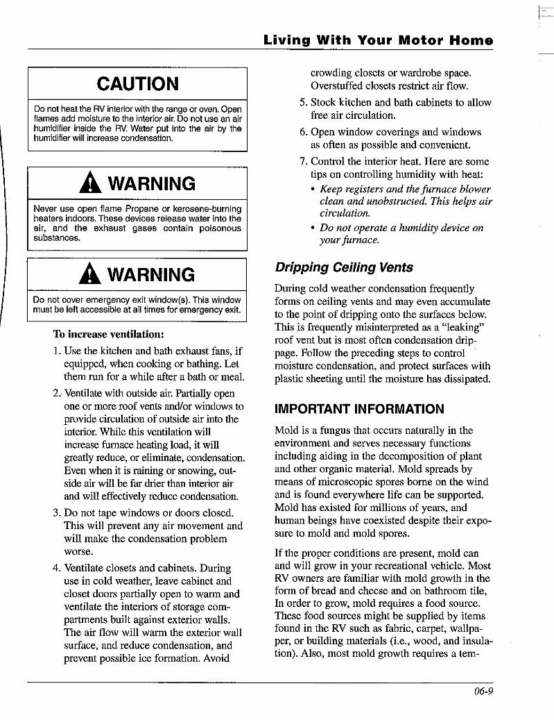
CAUTION Do not heat the RV interior with the range or oven. Open flames add moisture to the interior air. Do not use an air humidifier inside the RV. Water put into the air by the humidifier will increase condensation.
A WARNING Never use open flame Propane or kerosene-burning heaters indoors. These devices release water into the air, and the exhaust gases contain poisonous substances.
A WARNING Do not cover emergency exit window(s). This window must be left accessible at all times for emergency exit.
To increase ventilation:
1. Use the kitchen and bath exhaust fans, if equipped, when cooking or bathing. Let them run for a while after a bath or meal.
2. Ventilate with outside air. Partially open one or more roof vents and/or windows to provide circulation of outside air into the interior. While this ventilation will increase furnace heating load, it will greatly reduce, or eliminate, condensation. Even when it is raining or snowing, outside air will be far drier than interior air and will effectively reduce condensation.
3. Do not tape windows or doors closed. This will prevent any air movement and will make the condensation problem worse.
4. Ventilate closets and cabinets. During use in cold weather, leave cabinet and closet doors partially open to warm and ventilate the interiors of storage compartments built against exterior walls. The air flow will warm the exterior wall surface, and reduce condensation, and prevent possible ice formation. Avoid
Living With Your Motor Home
crowding closets or wardrobe space. Overstuffed closets restrict air flow.
S. Stock kitchen and bath cabinets to allow free air circulation.
6. Open window coverings and windows as often as possible and convenient.
7. Control the interior heat. Here are some tips on controlling humidity with heat: • Keep registers and the furnace blower
clean and unobstructed. This helps air circulation.
• Do not operate a humidity device on your furnace.
Dripping Ceiling Vents
During cold weather condensation frequently forms on ceiling vents and may even accumulate to the point of dripping onto the surfaces below. This is frequently misinterpreted as a "leaking" roof vent but is most often condensation drippage. Follow the preceding steps to control moisture condensation, and protect surfaces with plastic sheeting until the moisture has dissipated.
IMPORTANT INFORMATION
Mold is a fungus that occurs naturally in the environment and serves necessary functions including aiding in the decomposition of plant and other organic material. Mold spreads by means of microscopic spores borne on the wind and is found everywhere life can be supported. Mold has existed for millions of years, and human beings have coexisted despite their exposure to mold and mold spores.
If the proper conditions are present, mold can and will grow in your recreational vehicle. Most RV owners are familiar with mold growth in the form of bread and cheese and on bathroom tile, In order to grow, mold requires a food source. These food sources might be supplied by items found in the RV such as fabric, carpet, wallpaper, or building materials (i.e., wood, and insulation). Also, most mold growth requires a tem-
06-9
Living With Your Motor Home
perate climate. The best growth occurs at temperatures between 40°F and lOO°F. Most importantly, mold growth requires moisture, and moisture is the only growth factor that can be controlled. By minimizing interior sources of moisture, an RV owner can reduce or prevent mold growth. However, if optimal growth conditions persist, mold can develop within 24 to 48 hours.
Moisture in the RV can stem from a variety of sources such as spills, leaks, overflows, condensation, damp or standing water and human activity such as showering or cooking. Good maintenance practices are essential in the effort to prevent or reduce mold growth.
What the RV Owner Can Do
The RV owner can take positive steps to reduce the occurrence of mold growth in the RV and thereby minimize any possible adverse effects that may be caused by mold.
These steps may include, but are not limited to, the following:
• Before bringing items into the RV check for signs of mold. Potted plants (root and soil), furnishings, or stored clothing and bedding materials may also contain mold spores.
• Regular vacuuming and cleaning will help reduce levels of settled mold spores. Additionally, detergent solutions and most tile cleaners are effective in controlling mold growth on surfaces.
• Keep the humidity in the RV below 40%. Ventilate kitchens and bathrooms by opening windows, using exhaust fans, or running the air conditioning to remove excess moisture in the air and to facilitate evaporation of water from wet surfaces. In general, windows or doors through out the RV should be opened periodically to ventilate the RY.
• Promptly clean up spills, condensation, and other sources of moisture. Thoroughly dry any wet surfaces or material. Do not let water pool or stand in or under your RV.
06-10
• Inspect for leaks on a regular basis. Look for discolorations or wet spots. Repair any leaks promptly. Inspect condensation pans (refrigeration and air conditioners) for mold growth. Take notice of musty odors and any visible signs of mold growth.
Other actions the RV owner can take to prevent moisture issues include the following:
• Do NOT use unvented Propane, kerosene, or other unvented combustion heaters;
• Do NOT cover or close off the floor registers (if equipped);
• Check your cooling equipment filter on a monthly basis;
• Use the air conditioner or a dehumidifier during humid months, particularly during the summer in hot, humid climates;
• Use exhaust fans in kitchen and bathrooms to remove excess moisture;
• Clean the bathroom with mold-killing products
For more information about mold, and what you can do to reduce moisture and remediate mold growth in your RV, please refer to the following websites and literature;
1. U.S. Environmental Protection Agency. Mold Remediation in Schools and Commercial Buildings 2001. http'l!wwwepa gOY/iaQlmo]ds/moldremediatioD html
2. U.S. Environmental Protection Agency. A Brief Guide to Mold, Moisture, and Your Home, 2002. http·/Iwww<:pa goY/iaqimoldsimoldqnide hlml
FIRE SAFETY
The hazard and possibility of fire exists in all areas of life, and the recreational life-style is no exception. Your RV is a complex machine made up of many materials, some of them flammable. But like most hazards, the possibility of fire can be minimized, if not totally eliminated, by recognizing the danger and practicing common sense, safety and maintenance habits.
Know where your fIre extinguisher is located and how and when to use it. Read the instructions on the fIre extinguisher. Remember that portable fIre extinguishers are intended for use by the occupants of a building or area that is threatened by fIre. They are most valuable when used immediately on small fIres. They have a liruited amount of fIre-extinguishing material, and therefore must be used properly so this material is not wasted.
Fire extinguishers are pressurized, mechanical devices. They must be handled with care and treated with respect. They must be maintained as outlined in any maintenance instructions provided with the device so they are ready to operate properly and safely. Parts or internal chemicals may deteriorate in time and need replacement. Always follow maintenance and recharging instructions provided by the fIre extinguisher manufacturer. Maintain proper charge in the fIre extinguisher.
A. WARNING Urethane foam is flammable! Do noiexpose urethane foams to open flames or any other direct or indirect high temperature sources of ignition such as burning operations, welding, burning cigarettes, space heaters or unprotected electric light bulbs. Once ignited, urethane foams will burn rapidly, releasing great heat and consuming oxygen very quickly. In an enclosed space the resulting deficiency of oxygen will present a danger of suffocation to the occupants. Hazardous gases released by the burning foam can be incapacitating or fatal to human beings if inhaled in sufficient quantities.
Fire Safety Precautions
In addition to instructing occupants on what to do in case of fIre, and holding fIre drills periodically, consider these fIre safety suggestions:
• If you experience a fIre while traveling, maintain control of the vehicle until you can safely stop. Evacuate the vehicle as quickly and safely as possible.
• If you experience a fIre while camped, evacuate the vehicle as quickly and safely
Living With Your Motor Home
as possible.
• Consider the cause and severity of the fIre and risk involved before trying to put it out. If the fIre is major or is fuel-fed, stand clear of the vehicle and wait for the fIre department or other emergency assistance.
• If your RV is damaged by fIre, do not move or live in it until you have had it thoroughly examined and repaired.
Just as in your home, included below are some common sense tips to help prevent a fIre incident from occurring.
• Never leave unattended food cooking on the stove or in the oven.
• Never smoke in bed or leave cigars/cigarettes unattended.
• Keep candles or any open flames away from curtains/fabrics/walls and ceiling.
• Keep matches and igniter devices safely stored and away from small children.
• Do not store combustibles inside your RV (gasoline, charcoal lighter, etc.).
A. WARNING Do not store or carry Propane containers, or other flammable liquids inside your recreational vehicle.
A. WARNING Explosive fuel clouds may be present at fuel filling stations. Before refueling (either gasoline, diesel fuel or Propane) be sure to turn off all pilot flames and appliances In your motor home. TUrning off the Propane at the tank is insufficient. Pilotless appliances may still spark or pilot flames may not extinguish immediately.
Living With Your Motor Home
Smoke Detector/Alarm
A battery-powered smoke detector/alarm is mounted on the ceiling in the living/cooking area of your motor home. Please read the smoke detector/alarm operating instructions for details on testing and caring for this important safety device.
Test the smoke detector/alarm after the motor home has been in storage, before each trip, and at least once a week during use.
The smoke detector/alarm should never be disabled due to nuisance or false alarm from cooking smoke, a dusty furnace, etc.
06-12
Ventilate your motor home with fresh air and the detector/alarm will shut off. Do not disconnect the battery.
Replace the battery once a year or immediately when the low battery BEEP signal sounds.
If the smoke detector/alarm fails to operate with new batteries, replace it with a new unit, available through an authorized Fleetwood Dealer.
, , ------L----
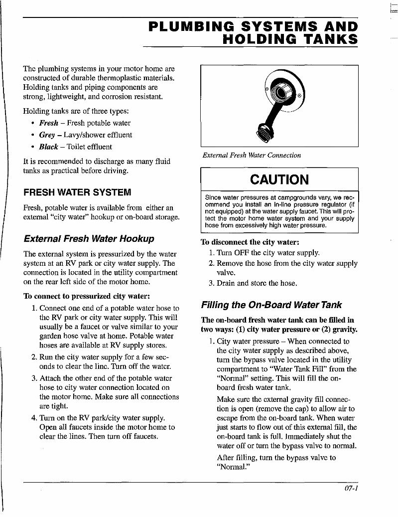
PLUMBING SYSTEMS AND HOLDING TANKS
The plumbing systems in your motor home are constructed of durable thermoplastic materials. Holding tanks and piping components are strong, lightweight, and corrosion resistant.
Holding tanks are of three types:
• Fresh - Fresh potable water
• Grey - Lavy/shower effluent
• Black - Toilet effluent
It is recommended to discharge as many fluid tanks as practical before driving.
FRESH WATER SYSTEM
Fresh, potable water is available from either an external "city water" hookup or on-board storage.
External Fresh Water Hookup
The external system is pressurized by the water system at an RV park or city water supply. The connection is located in the utility compartment on the rear left side of the motor home.
To connect to pressurized city water:
1. Connect one end of a potable water hose to the RV park or city water supply. This will usually be a faucet or valve similar to your garden hose valve at home. Potable water hoses are available at RV supply stores.
2. Run the city water supply for a few seconds to clear the line. Tum off the water.
3. Attach the other end of the potable water hose to city water connection located on the motor home. Make sure all connections are tight.
4. Tum on the RV park/city water supply. Open all faucets inside the motor home to clear the lines. Then tum off faucets.
External Fresh Water Connection
CAUTION Since water pressures at campgrounds vary, we recommend you install an in-line pressure regulator (if not equipped) at the water supply faucet. This will protect the motor home water system and your supply hose from excessively high water pressure.
To disconnect the city water: 1. Tum OFF the city water supply. 2. Remove the hose from the city water supply
valve. 3. Drain and store the hose.
Filling the On-Board Water Tank
The on-board fresh water tank can be filled in two ways: (1) city water pressure or (2) gravity.
1. City water pressure - When connected to the city water supply as described above, tum the bypass valve located in the utility compartment to "Water Tank Fill" from the "Normal" setting. This will fill the onboard fresh water tank.
Make sure the external gravity fill connection is open (remove the cap) to allow air to escape from the on-board tank. When water just starts to flow out of this external fill, the on-board tank is full. Immediately shut the water off or tum the bypass valve to normal.
After filling, tum the bypass valve to "Normal."
07-1
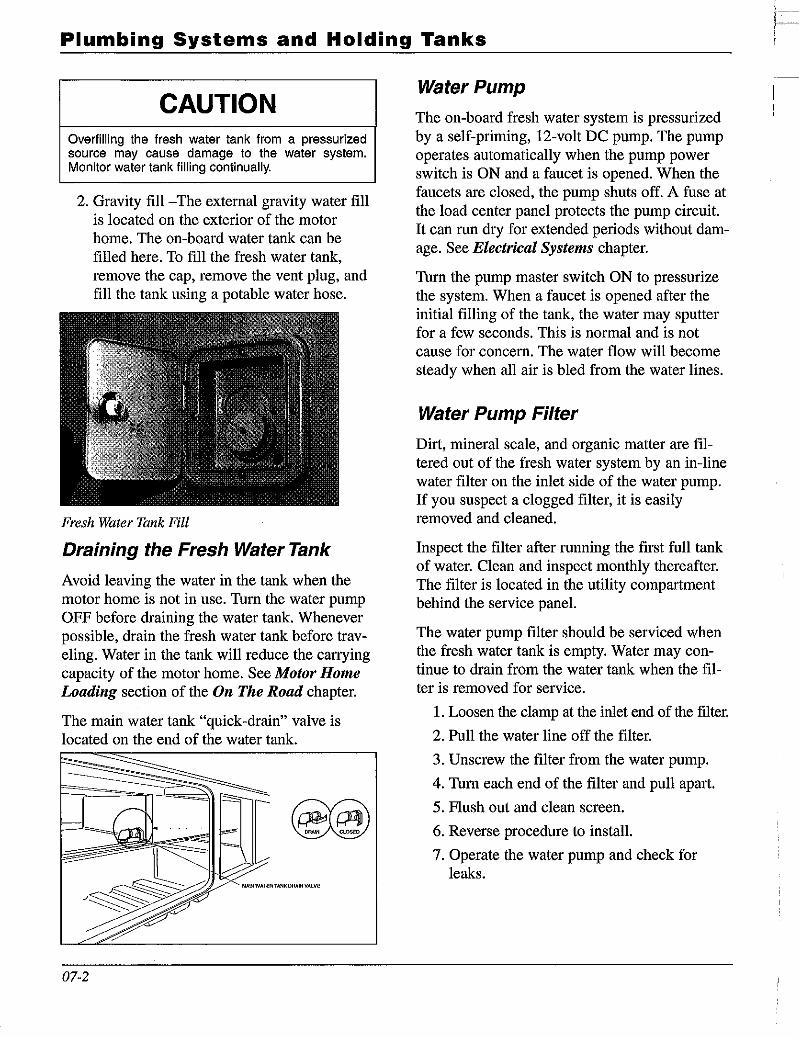
Plumbing Systems and Holding Tanks
CAUTION Overfilling the fresh water tank from a pressurized source may cause damage to the water system. Monitor water tank filling continually.
2. Gravity fill -The external gravity water fill is located on the exterior of the motor home. The on-board water tank can be filled here. To fill the fresh water tank, remove the cap, remove the vent plug, and fill the tank using a potable water hose.
Fresh Water Tank Fill
Draining the Fresh Water Tank
Avoid leaving the water in the tank when the motor home is not in use. Turn the water pump OFF before draining the water tank. Whenever possible, drain the fresh water tank before traveling. Water in the tank will reduce the carrying capacity of the motor home. See Motor Home Loading section of the On The Road chapter.
The main water tank "quick-drain" valve is located on the end of the water tank.
~ "
MAIN WAUR TANKDItUI VALVe
07-2
Water Pump
The on-board fresh water system is pressurized by a self-priming, l2-volt DC pump. The pump operates automatically when the pump power switch is ON and a faucet is opened. When the faucets are closed, the pump shuts off. A fuse at the load center panel protects the pump circuit. It can run dry for extended periods without damage. See Electrical Systems chapter.
Turn the pump master switch ON to pressurize the system. When a faucet is opened after the initial filling of the tank, the water may sputter for a few seconds. This is normal and is not cause for concern. The water flow will become steady when all air is bled from the water lines.
Water Pump Filter
Dirt, mineral scale, and organic matter are filtered out of the fresh water system by an in-line water filter on the inlet side of the water pump. If you suspect a clogged filter, it is easily removed and cleaned.
Inspect the filter after running the first full tank of water. Clean and inspect monthly thereafter. The filter is located in the utility compartment behind the service panel.
The water pump filter should be serviced when the fresh water tank is empty. Water may continue to drain from the water tank when the filter is removed for service.
1. Loosen the clamp at the inlet end ofthe filter.
2. Pull the water line off the filter.
3. Unscrew the filter from the water pump.
4. Turn each end of the filter and pull apart.
5. Flush out and clean screen.
6. Reverse procedure to install.
7. Operate the water pump and check for leaks.
Plumbing Systems and Holding Tanks
Low Point Drains
To drain hot and cold lines:
1. Open hot and cold low point drains.
2. Open the shower handle and faucet until all water has drained from the lines.
Troubleshooting the Fresh Water System
Water system problems usually fall into two categories: Inherent system problems, and problems caused by neglect. System problems are usually the result of road vibration and campsite water pressure variations. Problems of neglect usually stem from failure to clean filters, improper winterization, and poor battery maintenance. Most water system problems can be avoided by conscientious maintenance.
Leaks
Vibration, flexing and twisting while traveling can work pipe fittings loose. Check all plumbing for lea]cs at least once a year. If the water pump runs when a faucet is not open, suspect a leak. Be sure the tank drain valves are tightly closed. Leaks occur most often around threaded fittings. If necessary, tighten or clean and tighten the fittings. Do not overtighten fittings. Connections at galley and lavy fixtures should not be tightened with a wrench. They will normally seal with hand-tightening. If a leak persists at one of the fittings, disconnect it completely and check for mineral deposits or other foreign matter at the seating surfaces. Clean the surfaces thoroughly and reinstall the fitting.
Connections at the water tank, pump and valves are made with special clamps. They can be replaced with standard automotive type hose clamps.
Leaks caused by freezing damage can be prevented by proper winterization of the system. See the Storage chapter of this manual. Freezing damage is usually extensive and may
include a burst water tank, split piping, and a damaged water pump, toilet, and water heater. If you experience this type of damage, repairs can best be made by an authorized Fleetwood dealer.
For your safety, the shower faucet is equipped with a vacuum breaker device. This device is designed to prevent backflow of water into the fresh water system, reducing the possibility of contamination of the water supply. When the faucet is in the OFF position with the shower hose held above the faucet, water will drain out of the vacuum breaker. This drainage is not a defect, but indicates that the faucet is working correctly.
Sanitizing the Fresh Water System
As approved by the U.S. Public Health Service, sanitize the fresh water tank and piping system whenever the system may have become contaminated, has not been used for a period of time, or before long periods of storage. This will dis- . courage the growth of bacteria and other organisms that can contaminate the water supply. Use a chlorine/fresh water rinse as follows:
1. Prepare a solution of V4-cup household liquid chlorine bleach (5% sodium hypochlorite) to one gallon of water. Use one gallon solution for each 15 gallons of tank capacity.
2. Close drain valves and faucets, pour the chlorine solution into the exterior fresh water tank filler spout, and complete filling at tank with potable water.
3. Turn water pump switch ON. (Be sure you have l2-volt DC power.) Open all faucets individually until water flows steadily, then turn them off. This will purge any air from the lines.
4. Top off water tank with fresh water and allow the system to stand for at least 4 hours.
5. Drain the entire system by opening all potable water tank valves, plumbing line drain valves, and operating faucets.
07-3
Plumbing Systems and Holding Tanks
6. Flush the system with potable water. Let the fresh water flow through the system for several minutes to flush out the chlorine solution.
7. After you stop the flushing, close the tank valve, drain valves, and faucets. You can now fill the tank with potable water, and the system is ready to use.
Exterior Shower (If Equipped)
A shower fixture is mounted in the exterior utility compartment. The water pump must be ON or city water pressure must be available for the shower to operate. Close the exterior shower valves when finished using.
Whole Coach Water Filter System (If Equipped)
The water filter helps provide consistent drinking water,quality to the entire water system. The filter cartridge is located in the service panel compartment. your Owner's Information Package contains detailed operating and maintenance instructions concerning this system.
~I NOTE I Turn water pump off before traveling. Road vibration could cause a faucet to open. If the water pump is on, your fresh water supply could be pumped into the holding tank.
WASTE WATER SYSTEM
The waste water system in your RV is made up of sinks, tub, shower, toilet, plumbing drain and vent lines, a "gray water" holding tank and a "black water" holding tank. The gray tank holds shower, tub and sinks, where the black tank holds toilet effluent. The holding tanks make the system completely self-contained and allow you to dispose of waste water at your convenience. A flexible sewer hose i& required to connect the holding tank outlet to the inlet of an approved waste water dump station or sewer system.
07-4
The drain plumbing is very similar to that used in your home. The system is trapped and vented to prevent waste gases from backing up into the RV. The drain plumbing is made of plastic, and is durable and resistant to most chemicals. All drain plumbing except the toilet connection terminates in the gray water holding tank and drains directly into it.
Toilet
Your RV is equipped with a marine-type toilet. The flushing mechanism, whether a foot-operated pedal or a hand-operated lever, allows a valve in the bottom of the bowl to open, permitting the contents to be flushed into the "black" holding tank. A stream of water under pressure from the RV's water system swirls around the bowl, cleaning it and flushing the contents into the holding tank. Most models have two levers, each working independently of the other so the bowl can be filled with water prior to use.
In order to help prevent hard deposits from building up within the "black" tank and help reduce unwanted odor, it is recommended to always keep water in the tank. When empty after a tank discharge, flush the toilet several times in order to introduce about five gallons of water.
It is highly recommended that a deodorizing product should be used for the black tank after each discharge at a dumping station. This will help control unwanted odors.
Ensure that the black tank sewer drain system is always closed and only opened when draining at a dump station. Never allow your black tank system to dry out unless it has been thoroughly cleaned, sanitized and rinsed first.
For additional information, please refer to the operating manual in your Owner's Information Package.
j---L~_
Plumbing Systems and Holding Tanks
Draining the Holding Tanks
The holding tanks terminate in a valve arrangement that permits draining each tank separately.
The valves are called knife valves. A blade closes the opening in the sewer drain pipes. The blade is connected to a T-handle and cable assembly mounted in the utility compartment. Pull the T-handle to release the contents of the tank(s).
During self-containment use, the sewer line is securely capped to prevent leakage of waste material onto the ground or pavement. Do not pull the holding tank knife valve open when the protective cap is installed on the pipe. Always drain the tank into an acceptable sewer inlet or dump station.
Drain the holding tanks only when they are at least %-full. If necessary, fill the tanks with water to %-full. This provides sufficient water to allow complete flushing of waste material into the sewer line.
Wheneyer possible, drain the holding tanks before traveling. Waste water and sewage in the holding tanks reduce the carrying capacity of the motor home. See the Motor Home Loading chapter.
During extended or semi-permanent hookups to sewage systems, waste materials will build up in the tank and cause serious plugging if the tank valves are continuously open. In these cases, keep the valves closed until the tanks are 'l'4-full, and then drain into the sewage system.
The holding tank drain valve outlet is to be used with a removable termination fitting that locks onto the outlet with a clockwise twist. Clamp the sewer drain hose to this fitting. A protective cap should remain in place when you are not draining the tanks.
A WARNING Holding tanks are enclosed sewer systems and as such must be drained into an approved dump station. Both black and gray water holding tanks must be drained and thoroughly rinsed regularly to prevent accumulation of harmful or toxic materials.
~I NOTE I Local or state regulations may prohibit highway travel unless the holding tank outlet is securely capped.
To drain the holding tanks:
1. Attach the sewer hose to the holding tank outlet. Insert the end of the hose into the sewer or dump station inlet, pushing it firmly far enough into the opening to be secure. In some cases, adapters may be necessary or required between the line and the inlet. Arrange the sewer hose so it slopes evenly.
2. Drain the black water holding tank first. Grasp the handle of the black water knife valve (the large one) firmly and slide the valve open with a quick, steady pull.
3. Allow enough time for the tank to drain completely. Rinse and flush the tank through the toilet. When the tank is empty, push the handle in to close the valve. Run enough water (up to five gallons or so) into the tank to cover the bottom. This will aid the break up of solid wastes, and reduce "pyramiding" of waste material.
4. To drain the gray water tank, repeat the steps above using the small knife valve. This tank is drained last to aid in flushing the outlets and hose. The gray water knife valve may be left open in a semi-permanent hookup.
S. See the tank flush system instructions in the next section if your recreational vehicle is so equipped.
07-5
1-I~--
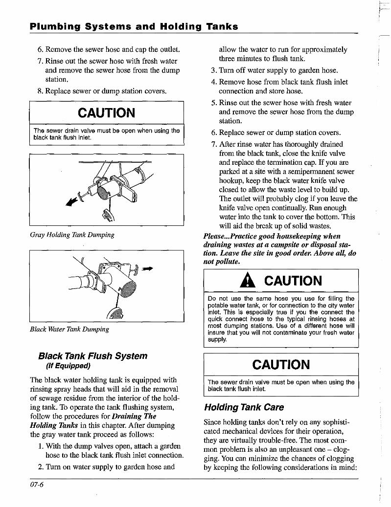
Plumbing Systems and Holding Tanks
6. Remove the sewer hose and cap the outlet.
7. Rinse out the sewer hose with fresh water and remove the sewer hose from the dump station.
8. Replace sewer or dump station covers.
CAUTION The sewer drain valve must be open when using the black tank flush inlet.
Gray Holding Tank Dumping
Black Water Tank Dumping
Black Tank Flush System (If Equipped)
The black water holding tank is equipped with rinsing spray heads that will aid in the removal of sewage residue from the interior of the holding tank. To operate the tank flushing system, follow the procedures for Draining The Holding Tanks in this chapter. After dumping the gray water tank proceed as follows:
1. With the dump valves open, attach a garden hose to the black tank flush inlet connection.
2. Turn on water supply to garden hose and
07-6
allow the water to run for approximately three minutes to flush tank.
3. Turn off water supply to garden hose.
4. Remove hose from black tank flush inlet connection and store hose.
S. Rinse out the sewer hose with fresh water and remove the sewer hose from the dump station.
6. Replace sewer or dump station covers.
7. After rinse water has thoroughly drained from the black tank, close the knife valve and replace the termination cap. If you are parked at a site with a semipermanent sewer hookup, keep the black water knife valve closed to allow the waste level to build up. The outlet will probably clog if you leave the knife valve open continually. Run enough water into the tank to cover the bottom. This will aid the break up of solid wastes.
Please ... Practice good housekeeping when draining wastes at a campsite or disposal station. Leave the site in good order. Above all, do not pollute.
A CAUTION Do not use the same hose you use for filling the potable water tank, or for connection to the city water inlet. This is especially true if you the connect the quick connect hose to the typical rinsing hoses at most dumping stations. Use of a different hose will insure that you will not contaminate your fresh water supply.
CAUTION The sewer drain valve must be open when using the black tank flush inlet.
Holding Tank Care
Since holding tanks don't rely on any sophisticated mechanical devices for their operation, they are virtually trouble-free. The most common problem is also an unpleasant one - clogging. You can minimize the chances of clogging by keeping the following considerations in mind:
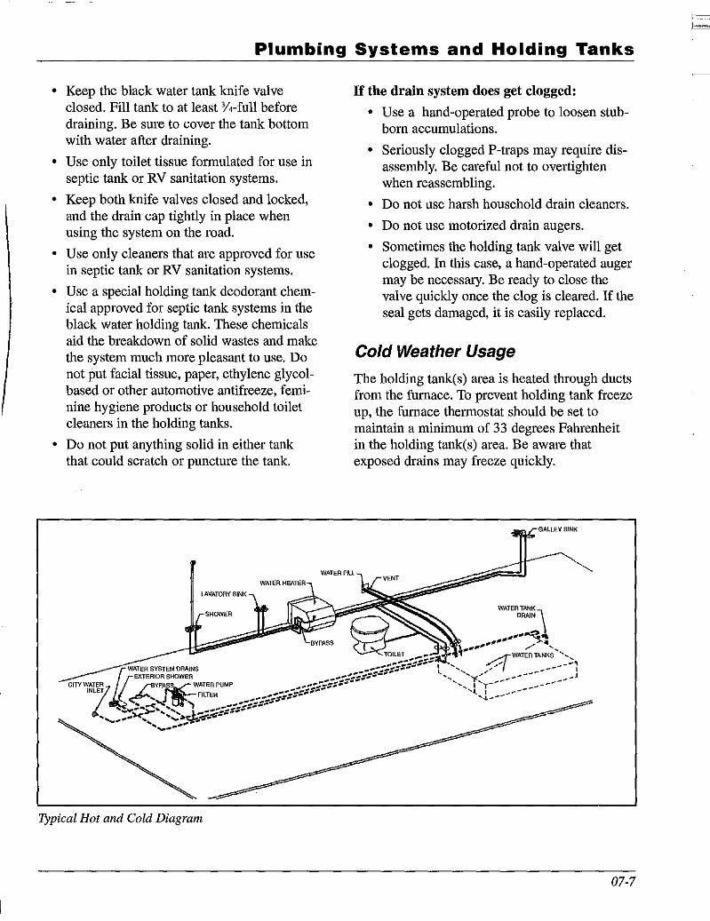
Plumbing Systems and Holding Tanks
• Keep the black water tank knife valve closed. Fill tank to at least 'I.-full before draining. Be sure to cover the tank bottom with water after draining.
• Use only toilet tissue formulated for use in septic tank or RV sanitation systems.
• Keep both knife valves closed and locked, and the drain cap tightly in place when using the system on the road.
• Use only cleaners that are approved for use in septic tank or RV sanitation systems.
• Use a special holding tank deodorant chemical approved for septic tank systems in the black water holding tank. These chemicals aid the breakdown of solid wastes and make the system much more pleasant to use. Do not put facial tissue, paper, ethylene glycolbased or other automotive antifreeze, feminine hygiene products or household toilet cleaners in the holding tanks.
• Do not put anything solid in either tank that could scratch or puncture the tank.
Typical Hot and Cold Diagram
If the drain system does get clogged:
• Use a hand-operated probe to loosen stubborn accumulations.
• Seriously clogged P-traps may require disassembly. Be careful not to overtighten when reassembling.
• Do not use harsh household drain cleaners.
• Do not use motorized drain augers.
• Sometimes the holding tank valve will get clogged. In this case, a hand-operated auger may be necessary. Be ready to close the valve quickly once the clog is cleared. If the seal gets damaged, it is easily replaced.
Cold Weather Usage
The holding tank(s) area is heated through ducts from the furnace. To prevent holding tank freeze up, the furnace thermostat should be set to maintain a minimum of 33 degrees Fahrenheit in the holding tank(s) area. Be aware that exposed drains may freeze quickly.
GALLEY SINK
07-7
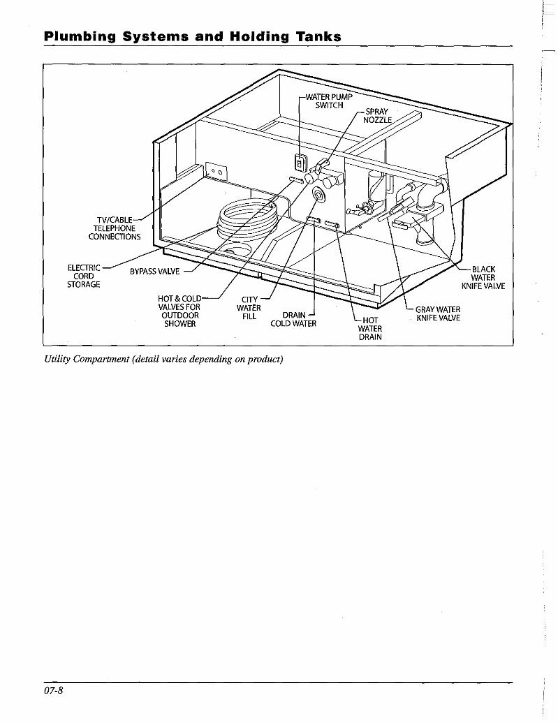
Plumbing Systems and Holding Yanks
TV/CABLE TELEPHONE
CONNECTIONS
ELECTRIC CORD
STORAGE
BYPASS VALVE
HOT&COLD VALVES FOR OUTDOOR SHOWER
WATER PUMP SWITCH
DRAIN COLDWATER
Utility Compartment (detail varies depending on product)
07-8
SPRAY NOZZLE
GRAY WATER KNIFE VALVE
ELECTRICAL SYSTEMS
Your motor home is equipped with three electrical systems:
the chassis 12-volt system the Fleetwood 12-volt house system the 120-volt AC system.
They operate together to give you electrical power for many different situations.
CHASSIS 12-VOLT ELECTRICAL SYSTEM
The chassis 12-volt or vehicle electrical system generally includes:
the chassis battery chassislhouse battery charging system ignition system instrument panel and controls headlights, taillights, turn signals power entry step Propane detector/alarm leveling jacks (if equipped) slide-out (if equipped) fog lights (if equipped) air horns (if equipped) power seats (if equipped) radio luggage compartment lights other vehicle lights and accessories
Chassis Bulbs and Fuses
Exterior bulb types are listed in section 04-01 of this Owner's Manual. Always replace bulbs and fuses with equivalent types and ratings.
Fuses will interrupt the flow of electricity if a circuit is overloaded. The 12-volt chassis fuse panel is located under the driver's side instrument panel. Additional fuses are located under the hood, or in 12-volt power leads on the related equipment and accessories.
CAUTION Always replace bulbs and fuses with equivalent types. The type is marked on the bulb or fuse.
FLEETWOOD 12-VOLT HOUSE AND AUTOMOTIVE SYSTEM
This system generally includes:
all 12-volt interior lighting fIXtures & outlets
fresh water pump
12-volt accessories
House batteries provide 12-volt DC power. These batteries are not the chassis 12-volt batteries. Power is also provided by a DC converter that operates when the motor home electrical cord is plugged into l20-volt AC power source or by the generator (if equipped). The house batteries are charged by the motor hO(Ile engine alternator, or by the converter when it is operating.
.11 NOTE I Power for living area radios and tape decks is available from either the chassis or house batteries. A switch on the instrument panel allows you to select the power source. If you use the radio, tape decks, or other 12-volt DC equipment for long periods of time when the motor home engine is not running, either battery may be discharged.
Batteries
Your motor home has two battery systems. One system supplies 12-volt DC power to start the vehicle engine. The other system supplies 12-volt DC power to the house living area.
Battery Disconnect (If Equipped)
Some accessories or equipment such as clocks, radios or the refrigerator may draw small amounts of current even when turned OFF. For your convenience, relay operated disconnect circuits may be equipped with your motor home.
08-1
1-b=
Electrical Systems
These circuits isolate selected electrical systems from either the chassis or the house batteries. Activating the relay(s) will prevent battery discharge which may occur over extended storage periods. During normal use of your motor home the relays must always be in the "on" position.
If you plan to store the motor home for an extended period, press the disconnect switchles to OFF. Remember to press the switchles to ON when you take the motor home out of storage.
v'1 NOTE I A trouble shooting guide and function manual that explains this system is included with your motor home Owner's Information Package.
v'1 NOTE I When charging the batteries, the battery disconnect switches must be ON.
Battery Inspection and Care
A, WARNING Do not use the motor home when the chassis battery is disconnected. The power step will not operate as designed if the chassis battery is disconnected. If the step is not in the correct extended position, you may be injured if you step out of the motor home.
Check the external condition of the battery periodically. Look for cracks in the cover and case. Check the vent plugs and replace any that are cracked or broken. Keep the battery clean. Acid film and dirt on the battery top may permit current to flow between the terminals and discharge the battery.
To clean the battery:
1. Be sure the vent caps are installed and tight.
2. Wash the battery with a diluted solution of baking soda and water to neutralize any acid present.
3. Flush with clean water. Foaming around terminals or on top of the battery is normal acid neutralization. Avoid getting the soda solution in the battery.
08-2
4. Dry the cables and terminals.
5. Do not use grease on the bare metal inside the cable terminals to prevent corrosion. Grease is an insulator. Electricity will not flow through it. A plastic battery terminal spray will protect the terminals after you have cleaned and reinstalled them.
6. Check the battery, including water level, at least once a week. Keep the carrier and hold down hardware clean and free of corrosion and chemical accumulation.
A, WARNING Disconnect the 120-volt shore cord and the negative terminal from the battery/ies before working on either electrical system. If you work on the electrical systems with the power cord connected, you may be shocked, electrocuted, or severely burned.
Battery Charging
Both sets of batteries will be kept charged by the chassis engine alternator and charging system while you are driving. The DC power converter will charge the chassis and house batteries when plugged into l20-volt AC service or by the generator (if equipped). If the battery needs to be charged from a different charging source, please follow these safety guidelines:
• Leaving a charger connected to a battery for an extended period of time can shorten battery life.
• Do not smoke near batteries being charged or which have been recently charged. Please note that batteries are being charged while you drive, and while you are connected to l20-volt AC power through the converter! charger circuit.
• Do not break live circuits at the terminals of the battery. Use care when connecting or disconnecting booster leads or cables. Attaching booster cables, and poor connections are a common cause of electrical arcs which can cause explosion.
o Check and adjust the electrolyte level before charging. Fill each cell to the indicator with distilled water.
o Always remove all vent caps before charging the battery.
o Do not charge the battery at a rate that causes the electrolyte to spew out.
o In cold temperature storage conditions, batteries may freeze if not properly charged.
It.. WARNING Remove rings, metal watchbands, and other metal jew-elry before working around a battery. Use caution when using metal tools. If a tool contacts a battery terminal or metal connected to it, a short circuit could occur which could cause personal injury, explosion or fire.
It.. WARNING Do not allow battery electrolyte to contact skin, eyes, fabrics, or painted surfaces. The electrolyte is a sul-phuric acid solution which could cause serious per-sonal injury or property damage. Wear eye protection when working with batteries.
It.. WARNING Never expose the battery to open flame or electric spark. Chemical action in the battery generates hydrogen gas which is flammable and explosive. Do not allow battery electrolyte (acid) to contact skin, eyes, fabrics, or painted surfaces.
Solar Panel (If Equipped)
Your new motor home may be equipped with an optional solar charger. The solar charging panel installed on the roof of your motor home is designed to "trickle-charge" your battery system. It is not intended to be a fast charger. It also cannot supply large amounts of current to operate 12-volt DC electrical equipment. When the sky is clear and under bright sun, the solar panel will help keep your batteries "topped-up". Do not try to operate 12-volt DC appliances with the output of the solar paneL A light on the air conditioner indicates when the solar panel is operating.
Electrical Systems
Selecting a Replacement Battery When the battery requires replacement, always choose a battery with the same physical and electrical characteristics as the original equipment. Your dealer or an authorized Fleetwood Dealer can advise you on proper battery selection.
Auxiliary Start System (If Equipped)
You can use the Auxiliary Start System to start the motor home engine with the house battery if the chassis battery is discharged. The Auxiliary Start System has no effect on the vehicle except to aid in starting the motor home engine. If the vehicle alternator is operating properly, the batteries will be charged while driving.
To use the Auxiliary Start System:
1. Be sure the motor home is stopped. Shift the transmission to N or P and apply the parking brake.
2. Press and hold the Auxiliary Start switch on the instrument paneL
3. Start the engine with the ignition switch.
4. Hold the switch for at least 30 seconds after motor starts before releasing.
120-VOLT SYSTEM
This system provides grounded 120-volt AC electrical service for appliances such as air conditioners, TV, microwave ovens, etc. This system includes:
the generator the main electrical power cord ("shore cord")
Your motor home is equipped with a heavy duty, power cord. It is commonly called the "shore cord." This cord is used to connect to external 120-volt AC service. The cord and connector is molded together to form a weatherproof cable assembly. Do not cut or alter the cable in any way. Do not remove the ground pin in the cable connector, or defeat the ground circuit in the motor home.
To connect the power cord to external service, push the plug straight into the receptacle.
08-3
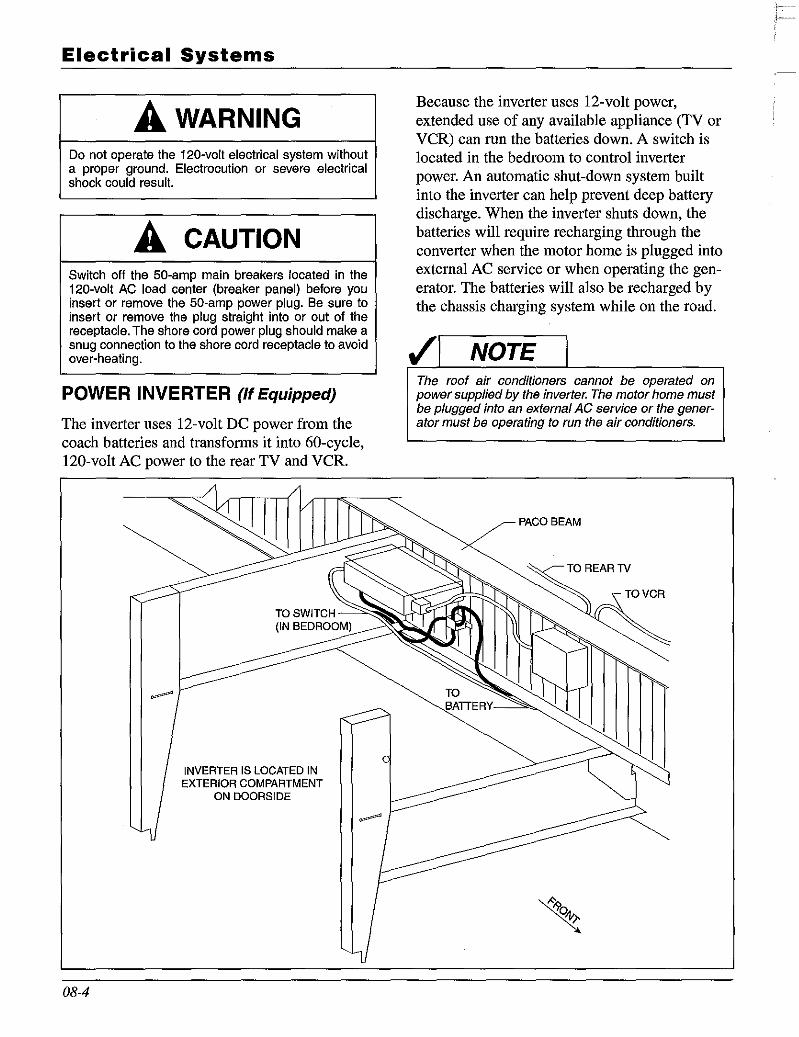
Electrical Systems
A. WARNING Do not operate the 120-volt electrical system without a proper ground. Electrocution or severe electrical shock could result.
A. CAUTION Switch off the 50-amp main breakers located in the 120-volt AC load center (breaker panel) before you insert or remove the 50-amp power plug. Be sure to insert or remove the plug straight into or out of the receptacle. The shore cord power plug should make a snug connection to the shore cord receptacle to avoid over-heating.
POWER INVERTER (If Equipped)
The inverter uses 12-volt DC power from the coach batteries and transforms it into 60-cycle, 120-volt AC power to the rear TV and VCR.
08-4
INVERTER IS LOCATED IN EXTERIOR COMPARTMENT
ON DOORS IDE
Because the inverter uses 12-volt power, extended use of any available appliance (TV or VCR) can run the batteries down. A switch is located in the bedroom to control inverter power. An automatic shut-down system built into the inverter can help prevent deep battery discharge. When the inverter shuts down, the batteries will require recharging through the converter when the motor home is plugged into external AC service or when operating the generator. The batteries will also be recharged by the chassis charging system while on the road.
.II NOTE I The roof air conditioners cannot be operated on power supplied by the inverter. The motor home must be plugged into an external AC service or the generator must be operating to run the air conditioners.
PACOBEAM
,/""" TO REAR TV
,1-=
Power Converter
The converter will automatically supply 12-volt DC power when your motor home is operating on 120-volt from the generator or a public utility. The DC power converter will charge the chassis and house batteries when plugged into 120-volt AC service or by the generator (if equipped).
Ground Fault Circuit Interrupter (GFCI)
Bathroom, galley, and patio 120-volt electrical outlets are protected by a Ground Fault Circuit Interrupter (GFCI). This device is intended to protect you against the hazards of electrical shocks possible when using electrical appliances in the bathroom or galley or in damp areas. Should a circuit or appliance (electric shaver, hair dryer, etc.) develop a potential shock hazard, the GFCI device is designed to disconnect the outlet (and other outlets on the same circuit), limiting your exposure time. Test the GFCI at least once a month. To test the GFCI:
.11 NOTE 1
If an outlet doesn't work, check the GFCI. Reset it if necessary. If the GFCI continues to trip, have the motor home electrical system checked at an authorized Fleetwood Dealer or by a qualified electrician.
1. Connect the main power cord to 120-volt AC.
2. Push the TEST button. The RESET button should pop out, indicating that the protected circuit has been disconnected.
3. If the RESET button does not pop out when the test button is pushed, a loss of ground fault protection is indicated. Do not use any electrical outlets. Have the motor home electrical system checked at an authorized Fleetwood Dealer or by a qualified electrician. Do not use the system until the problem has been corrected.
4. To restore power push the RESET button.
Electrical Systems
It.. WARNING Do not install 12-volt fuses or 120-volt breakers with amperage ratings greater than that specified on the device or label. Doing so constitutes a fire hazard.
Generator (If Equipped)
Your motor home may be equipped with a gasoline or Propane-powered generator which will provide complete electrical self-containment when regular public utility AC power is unavailable. Controls are at the generator and at a remote panel located in the living area of the motor home.
When the generator is operating, power is available at all of the 120-volt power outlets in the motor home, just as if the cord were connected to an external source. The generator is also connected to the power converter, thus supplying 12-volt power as well.
It.. WARNING Do not under any circumstances operate the generator while sleeping. You would not be able to monitor outside conditions to assure that generator exhaust does not enter the interior, and you would not be alert to exhaust odors or symptoms of carbon monoxide poisoning.
Generator Fuel Supply
Fuel for the gasoline or diesel generator is taken from the main fuel tank through a special feeder tube which is higher in the tank than the feeder tube to the motor home engine. This arrangement prevents the generator from running the motor home fuel tank dry.
Propane Generator (If Equipped)
Fuel is provided from a dedicated Propane tank.
Generator Operations
To start the generator:
I. Press generator remote switch until generator is running.
08-5
Electrical Systems
2. To stop the unit, press switch and release.
If the generator is slow to start, DO NOT hold the switch in the START position for more than 10 seconds. Release the switch, wait 15 seconds, then try to start again. This will help avoid overheating and damage to the generator starting system.
vl'1 NOTE I Refer to the generator operating instructions provided in your Owner's Information Package for information before starting the generator. Do not start the generator unit with a heavy power load. Always wait at least three minutes after starting generator before turning on (or plugging in) heavy electrical loads, such as the roof air conditioner.
Generator Operating Safety Precautions
Read and understand the generator operating, maintenance and safety instruction furnished in your Owner's Information Package.
• Do not smoke or use an open flame near the generator unit or fuel tank.
• Do not use generator ventilation air for heating any space.
• Check engine fuel lines. Fuel leakage in or around the compartment is an extreme fire hazard. Do not use the generator until fuel leaks are repaired.
• Check to be sure the generator exhaust pipe is located to discharge exhaust gases away from the RY.
• During stops while traveling, inspect the exhaust systems for road damage. Do not operate an engine with a damaged exhaust system.
• Be aware of exhaust gas (carbon monoxide) poisoning symptoms. Refer to the section on Carbon Monoxide Safety Precautions in the On The Road chapter.
• Check the generator exhaust system after every usage and whenever the system may have been damaged, and repair any leaks or obstructions before further operation.
• Check the exhaust systems( s) during routine
08-6
maintenance, and repair any leaks, damage, or obstructions before further operations.
• Disconnect the battery(ies) before performing any maintenance on the generator. Allow the generator to cool before performing any maintenance.
• Do not use the generator as an emergency power source to a general residential or industrial utility line. This is illegal and may cause shock or electrocution to power line utility personnel attempting to repair power lines.
A WARNING Do not place flammable material or store any other materials in the generator compartment.
A WARNING Do not operate the generator when parked in or near high grass or brush. Exhaust component heat may cause a fire.
it.. WARNING Do not modify the generator installation or exhaust system in any way. Do not use the generator as an emergency power source to a general residential or industrial utility line. This is illegal and may cause shock or electrocution to power line utility personnel attempting to repair power lines.
it.. WARNING Do not block the generator ventilating air inlets or outlets. The engine requires a constant supply of cooling air. Restricted ventilating air inlets or outlets can cause engine failure.
it.. WARNING Exhaust gases are deadly. Inspect the generator exhaust system thoroughly before starting the generator engine. Do not block the tail pipe or situate the motor home in a place where the exhaust gases have any possibility of accumulating either outside, underneath, or inside your vehicle or any nearby vehicles. Outside air movements can carry exhaust gases inside the vehicle through windows or other openings remote from the generator exhaust. Operate the generator only when safe dispersion of exhaust gases can be assured, and monitor outside conditions to be sure that exhaust gases continue to be dispersed safely.
ENERGY MANAGEMENT SYSTEM - 50 AMP FOR ADDITIONAL APPLICATION
Intellitec's Smart Energy Management System -50 AMP (Smart EMS) is designed to be used in RVs equipped with 50 AMP electrical service. The system senses when the coach is connected to a 50 AMP service and allows simultaneous operations of all the 120 volt loads. When 50 AMP service is not available and the coach is connected to a smaller electrical service, such as a generator source, 30 AMP or 20 AMP service, the system automatically takes control of the loads to practically eliminate circuit breaker tripping. It constantly monitors the total amount of
Electrical Systems
current drawn in the RV and controls the loads, as necessary, to keep the total current to a value less than, or equal to, the available power service.
There is no programming necessary and the unit will work with any load within the circuit breaker limits. The Smart EMS automatically "learns" the amount of current drawn by each of the controlled loads as it turns them "ON" and "OFF". In this way, it automatically adapts to differing loads or loads whose current changes with line voltage or temperature.
Features: • Energy Management of Generator source
and power (30/20) AMP.
• Minimizes circuit breaker tripping when connected to Generator Source, 30 AMP or 20 AMP service.
• Eliminates manual appliance select switches.
• Senses current of owner added loads. • Owner selectable 20 AMP operation from
remote panel. • Protects air conditioners with two minute
restart delay. • "Learns" controlled appliance current
draw.
v'1 NOTE I A troubleshooting guide and function manual that explains this system is included with your motor home Owner's Information Package.
ELECTRICAL WIRING DIAGRAMS
Because of the many model, floor plans and option variations available, it is beyond the scope of this manual to include wiring diagrams. In certain situations, specific wiring diagrams may be available to help troubleshoot a problem. If you need specific wiring information, please contact your dealer. Complete wiring diagrams are not available.
08-7
Electrical Systems
MOTOR HOME FUSES AND CIRCUIT BREAKERS
The l20-volt circuit breakers and 12-volt fuses are located on three separate panels. The purpose of these three panels is to provide electrical circuit breakers and fuses to interrupt current flow if a circuit is overloaded.
1. 120-volt House Electrical- This electrical panel is located under the bed or the refrigerator (location varies depending upon model). This panel is very similar to a residential panel with resettable breakers.
2. Fleetwood Automotive 12-volt System -This panel is located in a driver's side under the hood. This electrical center contains battery disconnect systems, entry step, fog light, and some other automotive circuitry.
3. 12-volt Chassis Fuses - This electrical panel is located under the driver's side dash area.
08-8
A WARNING Do not install 12-volt fuses or 120-volt breakers with amperage ratings greater than that specified on the device or label. Doing so constitutes a fire hazard.
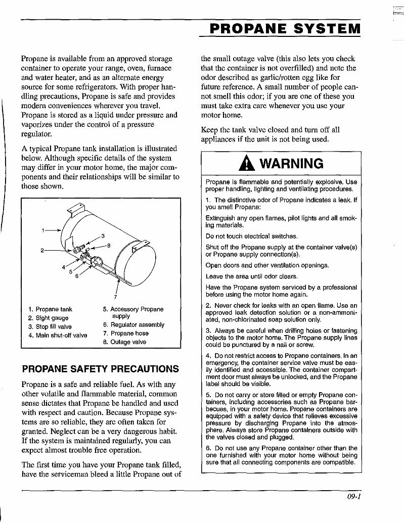
Propane is available from an approved storage container to operate your range, oven, furnace and water heater, and as an alternate energy source for some refrigerators. With proper handling precautions, Propane is safe and provides modern conveniences wherever you travel. Propane is stored as a liquid under pressure and vaporizes under the control of a pressure regulator.
A typical Propane tank installation is illustrated below. Although specific details of the system may differ in your motor home, the major components and their relationships will be similar to those shown.
2--~@i:l'
1. Propane tank 2. Sight gauge 3. Stop fill valve 4. Main shut-all valve
7
5. Accessory Propane supply
6. Regulator assembly 7. Propane hose S. Outage valve
PROPANE SAFETY PRECAUTIONS
Propane is a safe and reliable fuel. As with any other volatile and flammable material, common sense dictates that Propane be handled and used with respect and caution. Because Propane systems are so reliable, they are often taken for granted. Neglect can be a very dangerous habit. If the system is maintained regularly, you can expect almost trouble free operation.
The first time you have your Propane tank filled, have the serviceman bleed a little Propane out of
PROPANE SYSTEM
the small outage valve (this also lets you check that the container is not overfilled) and note the odor described as garlic/rotten egg like for future reference. A small number of people cannot smell this odor; if you are one of these you must take extra care whenever you use your motor home.
Keep the tank valve closed and turn off all appliances if the unit is not being used.
A WARNING Propane is flammable and potentially explosive. Use proper handling, lighting and ventilating procedures.
1. The distinctive odor of Propane indicates a leak. If you smell Propane:
Extinguish any open flames, pilot lights and all smoking materials.
Do not touch electrical switches.
Shut oil the Propane supply at the container valve(s) or Propane supply connection(s).
Open doors and other ventilation openings.
Leave the area until odor clears.
Have the Propane system serviced by a professional before using the motor home again.
2. Never check for leaks with an open flame. Use an approved leak detection solution or a non-ammoniated, non-chlorinated soap solution only.
3. Always be careful when drilling holes or fastening objects to the motor home. The Propane supply lines could be punctured by a nail or screw.
4. Do not restrict access to Propane containers. In an emergency, the container service valve must be easily identified and accessible. The container compartment door must always be unlocked, and the Propane label should be visible.
5. Do not carry or store filled or empty Propane containers, including accessories such as Propane barbecues, in your motor home. Propane containers are equipped with a safety device that relieves excessive pressure by discharging Propane into the atmosphere. Always store Propane containers outside with the valves closed and plugged.
6. Do not use any Propane container other than the one furnished with your motor home without being sure that all connecting components are compatible.
09-1
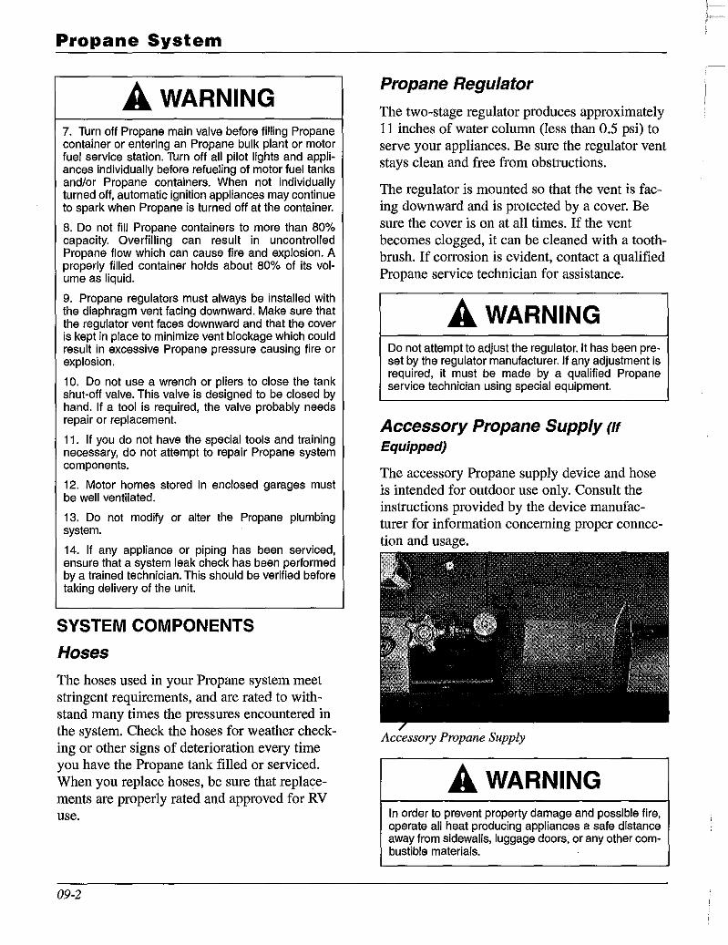
Propane System
it.. WARNING 7. Turn off Propane main valve before filling Propane container or entering an Propane bulk plant or motor fuel service station. Turn off all pilot lights and appliances individually before refueling of motor fuel tanks and/or Propane containers. When not individually turned off, automatic ignition appliances may continue to spark when Propane is turned off at the container.
8. Do not fill Propane containers to more than 80% capacity. Overfilling can result in uncontrolled Propane flow which can cause fire and explosion. A properly filled container holds about 80% of its volume as liquid.
9. Propane regulators must always be installed with the diaphragm vent facing downward. Make sure that the regulator vent faces downward and that the cover is kept in place to minimize vent blockage which could result in excessive Propane pressure causing fire or explosion.
10. Do not use a wrench or pliers to close the tank shut-off valve. This valve is designed to be closed by hand. If a tool is required, the valve probably needs repair or replacement.
11. If you do not have the special tools and training necessary, do not attempt to repair Propane system components.
12. Motor homes stored in enclosed garages must be well ventilated.
13. Do not modify or alter the Propane plumbing system.
14. If any appliance or piping has been serviced, ensure that a system leak check has been performed by a trained technician. This should be verified before taking delivery of the unit.
SYSTEM COMPONENTS
Hoses
The hoses used in your Propane system meet stringent requirements, and are rated to withstand many times the pressures encountered in the system. Check the hoses for weather checking or other signs of deterioration every time you have the Propane tank filled or serviced. When you replace hoses, be sure that replacements are properly rated and approved for RV use.
09-2
Propane Regulator
The two-stage regulator produces approximately 11 inches of water column (less than 0.5 psi) to serve your appliances. Be sure the regulator vent stays clean and free from obstructions.
The regulator is mounted so that the vent is facing downward and is protected by a cover. Be sure the cover is on at all times. If the vent becomes clogged, it can be cleaned with a toothbrush. If corrosion is evident, contact a qualified Propane service technician for assistance.
it.. WARNING Do not attempt to adjust the regulator. It has been preset by the regulator manufacturer. If any adjustment is required, it must be made by a qualified Propane service technician using special equipment.
Accessory Propane Supply (If Equipped)
The accessory Propane supply device and hose is intended for outdoor use only. Consult the instructions provided by the device manufacturer for information concerning proper connection and usage.
Accessory Propane Supply
it.. WARNING In order to prevent property damage and possible fire, operate all heat producing appliances a safe distance away from sidewalls, luggage doors, or any other combustible materials.
, ,~ ,-r
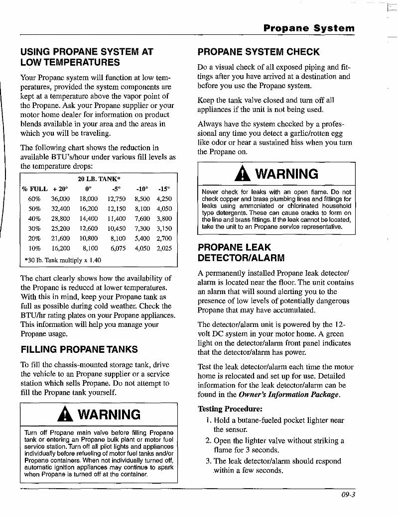
USING PROPANE SYSTEM AT LOW TEMPERATURES
Your Propane system will function at low temperatures, provided the system components are kept at a temperature above the vapor point of the Propane. Ask your Propane supplier or your motor home dealer for information on product blends available in your area and the areas in which you will be traveling.
The following chart shows the reduction in available BTU's!hour under various fill levels as the temperature drops:
20LB.TANK*
% FULL + 20' 0' _5' _10' _IS'
60% 36,000 18,000 12,750 8,500 4,250
50% 32,400 16,200 12,150 8,100 4,050
40% 28,800 14,400 11,400 7,600 3,800
30% 25,200 12,600 10,450 7,300 3,150
20% 21,600 10,800 8,100 5,400 2,700
10% 16,200 8,100 6,075 4,050 2,025
*30 lb. Tank multiply x 1.40
The chart clearly shows how the availability of the Propane is reduced at lower temperatures. With this in mind, keep your Propane tank as full as possible during cold weather. Check the BTU/hr rating plates on your Propane appliances. This information will help you manage your Propane usage.
FILLING PROPANE TANKS
To fill the chassis-mounted storage tank, drive the vehicle to an Propane supplier or a service station which sells Propane. Do not attempt to fill the Propane tank yourself.
A WARNING Turn off Propane main valve before filling Propane tank or entering an Propane bulk plant or motor fuel service station. Turn off all pilot lights and appliances individually before refueling of motor fuel tanks and/or Propane containers. When not individually turned off, automatic ignition appliances may continue to spark when Propane is turned off at the container.
Propane System
PROPANE SYSTEM CHECK
Do a visual check of all exposed piping and fittings after you have arrived at a destination and before you use the Propane system.
Keep the tank valve closed and turn off all appliances if the unit is not being used.
Always have the system checked by a professional any time you detect a garlic/rotten egg like odor or hear a sustained hiss when you turn the Propane on.
A WARNING Never check for leaks with an open flame. Do not check copper and brass plumbing lines and fittings for leaks using ammoniated or chlorinated household type detergents. These can cause cracks to form on the line and brass fittings. If the leak cannot be located, take the unit to an Propane service representative.
PROPANE LEAK DETECTOR/ALARM
A permanently installed Propane leak detector/ alarm is located near the floor. The unit contains an alarm that will sound alerting you to the presence of low levels of potentially dangerous Propane that may have accumulated.
The detector/alarm unit is powered by the 12-volt DC system in your motor home. A green light on the detector/alarm front panel indicates that the detector/alarm has power.
Test the leak detector/alarm each time the motor home is relocated and set up for use. Detailed information for the leak detector/alarm can be found in the Owner's Information Package.
Testing Procedure:
1. Hold a butane-fueled pocket lighter near the sensor.
2. Open the lighter valve without striking a flame for 3 seconds.
3. The leak detector/alarm should respond within a few seconds.
09-3
···1-.. -.. f=
Propane System
4. Press the mute button to reset the alarm.
5. Lightly fan the area around the detector! alarm to insure complete dispersion of the Propane from the lighter, and to prevent another sounding of the alarm.
6. A mute button allows you to temporarily quiet the alarm for 60 seconds after it has been set off or after testing.
7. If the alarm does not sound during a test or if the green indicator light is not visible, see your dealer or an authorized Fleetwood Dealer. There are no batteries or user serviceable parts inside the unit.
it.. WARNING The Propane leak detector/alarm will not function if both battery disconnects are OFF.
v"1 NOTE I The detector/alarm draws enough current to discharge your battery. Remember to turn off the chassis and house battery disconnects if you are not using your motor home.
09-4
LIGHTING PROPANE APPLIANCES
Detailed operating information for the Propane appliances can be found in your Owner's Information Package. Please read and follow these instructions.
Air trapped in the Propane lines may delay the initial lighting of any appliance. It could take several seconds or minutes for the Propane to reach the appliance. To purge some of the air from the Propane system, first light a burner on the range. The other appliances will then light more quickly.
The first time the furnace or oven is operated, paints and oils used in its manufacture may generate some smoke and fumes. If this occurs, open doors and windows to air out the motor home. These materials should burn off after the first 15 to 20 minutes of appliance operation.
Always follow the appliance manufacturer's lighting, operating and maintenauce instructions.
it.. WARNING The Propane detector/alarm is powered by a 12-volt source. Any interruption in power will render this alarm inoperative. Always ensure power is applied especially when appliances are in use.
j--1---
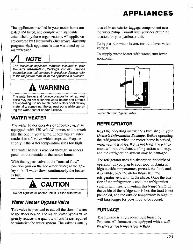
The appliances installed in your motor home are tested and listed, and comply with standards established by these organizations. All appliances are covered by Fleetwood's Ownercare Warran(y program. Each appliance is also warranted by its manufacturer.
.II NOTE I The individual appliance manuals incfuded in your Owner's Information Package contain detaifed operating and maintenance instructions. Always refer to the respective manual for the appliance in question.
A WARNING The water heater and furnace combustion air exhaust ports may be hot when the water heater and furnace are operating. Do not touch these outlets or allow any material to come near the exhaust ports while operat-ing the water heater and/or furnace.
WATER HEATER
The water heater operates on Propane, or, if so equipped, with 120-volt AC power, and is much like the one in your home. It contains an automatic shut off valve which stops the Propane supply if the water temperature rises too high.
The water heater is reached through an access panel on the outside of the motor home.
With the bypass valve in the "normal flow" position turn on the hot water faucet at the galley sink. If water flows continuously the heater is full.
A CAUTION Do not light water heater until it is filled with water.
Water Heater Bypass Valve
Thisvalve is provided to cut off the flow of water to the water heater. The water heater bypass valve greatly reduces the quantity of antifreeze required to winterize the water system. The valve is usually
APPLIANCES
located in an exterior luggage compartment near the water pump. Consult with your dealer for the location for your particular unit.
To bypass the water heater, turn the lever valve vertical.
To supply water heater with water, turn lever horizontal.
Water Heater Bypass Valve
REFRIGERATOR
Read the operating instructions furnished in your Owner's Information Package. Before operating the refrigerator when the motor home is parked, make sure it is level. If it is not level, the refrigerant will not circulate, cooling action will stop, and the refrigeration system may be damaged.
The refrigerator uses the absorption principle of operation. If you plan to cool food or drinks in high outside temperatures, precool the food, and, if possible, park the motor home with the refrigerator vent door in the shade. Once the interior of the refrigerator is cool, the refrigeration system will usually maintain this temperature. If the inside of the refrigerator is hot, the food is not precooled, and the outside temperature is high, it will take longer for your food to be cooled.
FURNACE
The furnace is a forced-air unit fueled by Propane. All furnaces are equipped with a wall thermostat for temperature setting.
10-1
,-b
Appliances
The furnace will not operate properly if your stored personal items block the free flow of air at the registers or the return air to the furnace. Storage under cabinets should be done carefully so as to not crush or damage any furnace ducting.
Smoke and fumes created as a result of burning off manufacturing compounds are sometimes present the first time the furnace is used. This is normal; however, when you light the furnace the first time, open all windows and doors until the residues are completely burned off.
Always follow the appliance manufacturer's lighting and operating instructiohs.
If the furnace does not keep you comfortably warm, NEVER use the range, oven or a catalytic heater for supplementary heat - even with a vent or window open.
Combustion air for the furnace comes from outside the RV. The products of combustion from the furnace (carbon dioxide, carbon monoxide and other gases) are returned to the outside air.
A WARNING Portable fuel-burning appliances are not safe for heating inside the motor home. Asphyxiation or carbon monoxide poisoning can occur.
RANGE
The Propane oven and burners are operated with Propane. The basic operation is the same as the range in your home.
A warning label has been located in the cooking area to remind you to provide an adequate supply of fresh air for combustion. Proper ventilation when using the cooking appliances will prevent the dangers of asphyxiation. Refer to Lighting Propane Appliances section in the Propane System chapter of this manual.
When you use the range oven for cooking or baking, always open a vent or window to provide ventilation. Never operate the range or oven
10-2
when you are sleeping or if your alertness is impaired in any way.
A WARNING Do not use open flames to warm the living area. Propane combustion consumes the oxygen inside the motor home.
RANGE EXHAUST HOOD
The exhaust hood allows vapors and cooking odors to escape, and may provide a vent for the galley area. Switches for the fan and light are located either on the range hood or the front of the microwave. The hood has grease filter screen(s) which require periodic cleaning. To clean, remove the screens and wash in soapy water. Rinse with water and let the screens drain dry.
If needed, replace the light bulb with an equivalent type found on the bulb or listed in the appliance owner's manual.
AIR CONDITIONER(S) (If Equipped)
The roof-mounted air conditioner(s) can operate only when the motor home is connected to 120-volt AC power from either a public utility or the generator. Be sure the air conditioner circuit breaker is ON.
Each return air duct is equipped with a filter. Check these filters at regular intervals for accumulations of dust that could restrict air flow.
For best performance, park the motor home in the shade and close curtains. Close doors and windows and turn the temperature control knob for desired coolness. Refer to the air conditioner manufacturer's instructions for detailed operating and preventive maintenance requirements. Remember that air conditioners use a large portion of your available electric power.
Ii
Experience has shown that some RV parks may experience reduced power (low voltage) on days with high heat or humidity, commonly referred to as a "brown out." This condition may result in the air conditioner circuit breaker tripping in your power distribution center. This protects your air conditioner motor from damage and is necessary during low voltage conditions. This breaker tripping is sometimes perceived as a fault in your motor home, but it is a necessary "safety valve."
.II NOTE I Your motor home is equipped with a ceiling-ducted air conditioning system. For most efficient operation, adjust each vent so that is completely open. If you change the vent opening to regulate air flow try not to restrict the vent opening to below 70% open. Restricting air flow below this opening will affect the efficiency of the air conditioner.
VCR, TELEVISIONS, DVD PLAYER (If Equipped)
All televisions, VCR and DVD players are set up to operate on a l20-volt AC power source. This source can be from the generator, shore cord or inverter.
ADDITIONAL 12-VOLT EQUIPMENT
If additional equipment requiring 12-volt power is installed in the motor home. Obtain the 12-volt source from a properly fused battery circuit. Consult an authorized Fleetwood dealer before adding any additional equipment to your motor home.
VIDEO EQUIPMENT
Video equipment can operate from inverter power or when the motor home is connected to l20-volt power from either a public utility or a generator.
Appliances
VIDEO CONTROL CENTER
The video control center, located near the VCR, allows routing of the antenna, cable, satellite, VCR or DVD signals to both the front and the rear TV's independent of each other. You can also use the control center to record signals from the antenna, cable, satellite and DVD (except copy protected material) to the VCR.
TV ANTENNA
The roof-mounted antenna is designed for reception of VHF and UHF television signals.
Before traveling, remember to lower the antenna and secure it to prevent damage to the antenna, motor home roof, or objects in the path of the antenna, such as overhead wires. Do not travel with the antenna raised.
Antenna Operating Instructions
Before raising antenna, check for clearance above the vehicle.
1. To raise the antenna to operating position, turn crank toward UP until you feel resistance. Switch the TV power ON.
2. To rotate antenna, pull down on rotating knob with both hands until it disengages the ceiling plate. Turn the antenna for best picture and sound. Do not rotate the antenna except in the full UP position.
3. To lower the antenna, first rotate it to align the pointer on the ceiling plate. Then turn the crank toward the down position; stop when resistance is felt. Never lower the antenna to any position without first aligning pointer.
4. Do not force antenna.
iO-3
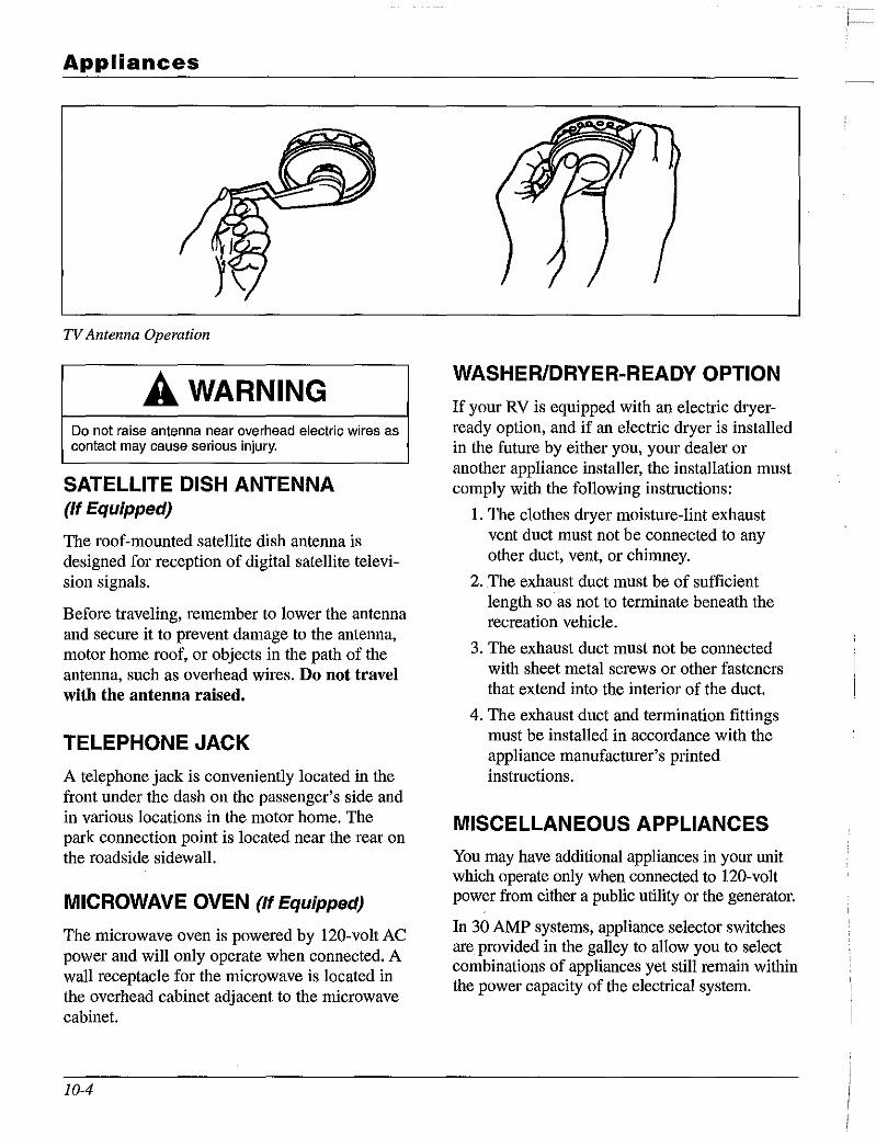
Appliances
TV Antenna Operation
A WARNING Do not raise antenna near overhead electric wires as contact may cause serious injury.
SATELLITE DISH ANTENNA (If Equipped)
The roof-mounted satellite dish antenna is designed for reception of digital satellite television signals.
Before traveling, remember to lower the antenna and secure it to prevent damage to the antenna, motor home roof, or objects in the path of the antenna, such as overhead wires. Do not travel with the antenna raised.
TELEPHONE JACK
A telephone jack is conveniently located in the front under the dash on the passenger's side and in various locations in the motor home. The park connection point is located near the rear on the roadside sidewall.
MICROWAVE OVEN (If Equipped)
The microwave oven is powered by 120-volt AC power and will only operate when connected. A wall receptacle for the microwave is located in the overhead cabinet adjacent to the microwave cabinet.
10-4
WASHER/DRYER-READY OPTION
If your RV is equipped with an electric dryerready option, and if an electric dryer is installed in the future by either you, your dealer or another appliance installer, the installation must comply with the following instructions:
1. The clothes dryer moisture-lint exhaust vent duct must not be connected to any other duct, vent, or chimney.
2. The exhaust duct must be of sufficient length so as not to terminate beneath the recreation vehicle.
3. The exhaust duct must not be connected with sheet metal screws or other fasteners that extend into the interior of the duct.
4. The exhaust duct and termination fittings must be installed in accordance with the appliance manufacturer's printed instructions.
MISCELLANEOUS APPLIANCES
You may have additional appliances in your unit which operate only when connected to 120-volt power from either a public utility or the generator.
In 30 AMP systems, appliance selector switches are provided in the galley to allow you to select combinations of appliances yet still remain within the power capacity of the electrical system.
[---, i--' ___ _
Your motor home has been designed to provide you with many years of use with a minimum amount of maintenance. This section will familiarize you with the areas of your motor home that require scheduled care. Time spent taking care of your motor home on a regular basis will pay for itself in extended service and will help protect your investment
If you are mechanically inclined and regularly perform routine maintenance and repairs on your car or truck, you may want to do the mechanical work on your motor home yourself. If you prefer, your dealer can perform these services for you. His trained personnel will assure that your motor home is maintained and repaired in keeping with original performance expectations.
This section is intended to provide the owner and operator with a general overview of service and maintenance information for the motor home. Detailed service and maintenance information may be found in the owner's/operator's manuals contained in the Owner's Information Package.
While the information in this section is intended to establish proper maintenance and inspection procedures, there may be times when detailed diagnostic and repair procedures may be required. Consult your dealer or an authorized Fleetwood Dealer in these situations.
EXTERIOR
Some exterior parts of your motor home are made of fiberglass. The finish on these parts is durable, but not indestructible. Any material and finish will deteriorate in time. Exposure to sunlight, moisture and airborne pollutants can cause dulling and fading of the finish. Generally, changes in the finish due to weathering are cosmetic - they are on the surface of the part and do not affect its strength. Weathering can take the form of chalking, fading and yellowing.
The best insurance against these effects is routine maintenance. If the finish is not washed and waxed thoroughly, the surface can deteriorate
MAINTENANCE
rapidly. The following maintenance guidelines can help you reduce these weathering effects:
1. When the motor home is not in use, keep the fiberglass surfaces out of the sun or covered with a canvas tarpaulin. Avoid using plastic or other nonporous materials which can trap moisture between the cover and the fiberglass surface.
2. Wash the exterior with a mild soap. Avoid strong alkaline cleaners and abrasives. For the best results, use a cleaner formulated for fiberglass, and follow the directions for using the cleaner. DO NOT use automatic dish· washer detergent, abrasives, bleaches, strong chemicals with acidslbases, or ammonia.
3. Wax the exterior at least once a year - twice, if possible - with a wax formulated for fiberglass. When waxing, always read and follow the instructions and precautions on the container. Some cleaners and waxes are recommended for use on only certain types of surfaces. As with automobiles, covered storage yields best results for longevity of exterior appearance and ease of maintenance.
4. In some cases, a light rubbing compound, finishing material, or other product advertised to restore fiberglass, may be required. Always follow the manufacturer's instructions. Always use a high-quality wax after treatment
Stains
Stains are generally caused by two types of substances - water soluble and non-water soluble. Water soluble stains can usually be washed away with water and mild detergent. Follow the washing with wax.
Non-water soluble stains are usually oil-based. Removal of this type of stain may require the use of highly flammable or poisonous solvents. Refer this type of service to your dealer or an authorized Fleetwood Dealer. Never use strong solvents or abrasives to clean plastic surfaces.
11-1
Maintenance
Exterior Graphics Care
The pressure sensitive graphics installed on the exterior surfaces of your motor home require little maintenance and should be treated similarly to a painted surface. Here are some guidelines to help you keep your exterior graphics looking like new.
1. Wash your graphics with any mild car wash soap solution. Be sure to rinse thoroughly.
2. Keep high-pressure wash nozzles at least 1 '12 feet from the edge of the graphics. High pressure spray may cause the edge of the graphic to lift and peel away from the wall surface.
3. Test any cleaning solution on a small section of the graphic before using the cleaning solution on a larger surface.
4. Do not use any aromatic solvents such as acetone, MEK, toluene, paint thinner, lacquer thinner on your graphics. Any solvent of this type may soften or smear colors.
5. Do not paint over the graphics with clear or any other type of paint.
6. Do not let gasoline or other fuels drip or stay on graphics for any length of time. If a spill occurs, wipe off and rinse with water immediately.
7. Do not apply wax over graphics, especially if the wax contains any petroleum distillates. Wax that has dried between stripes can be removed by softening it with rubbing (isopropyl) alcohol and cotton swabs. Be sure to rinse the area after cleaning.
8. Be careful when storing your motor home. The graphic materials should be protected from prolonged direct sunlight and heat.
Windows, Doors, Vents and Locks
Keep moving parts, hinges and latches adjusted and maintained. Lubricate with a light oil at least once a year. Check and tighten the screws holding the windows in place as required. Clean screens by gently wiping with a damp cloth or soft flat brush. Not all screens are removable.
11-2
Inspect the sealants aronnd doors and windows every three months. See Sealant Renewal section.
Lubricate locksets in doors and exterior storage compartments at least annually with powdered graphite. If the motor home is located at a beach or is exposed to salt air, more frequent lubrication may be required.
TPO ROOF SYSTEM
Cleaning
Your new motor home is equipped with a new roof material called TPO (thermoplastic olefin). For normal cleaning, standard household detergents or cleansers may be used. Use a nonabrasive, common household detergent and plenty of water. Be sure to keep the sidewalls wet to reduce streaking. For persistent, stubborn stains, use a whitewall tire cleaner. Follow directions on the cleaner container.
Care
The TPO roof itself does not require annual coatings or additional sealants. Periodic washing with soap and water is all that is required.
The TPO roof material can be cut by sharp objects. Use caution when loading sharp articles on the roof. If you add accessories or new equipment on the roof, be sure the installer is qualified to work on the TPO roof material. This is required under the terms of the warranty.
Repair kits are available through your dealer. The roof requires special adhesives and material. Do not use silicone sealants.
A. WARNING The TPO roof material is slippery when it is wet.
Sealant Renewal
This section outlines the procedures you must follow to maintain the weatherproof integrity of your motor home. Leak damage caused by fail-
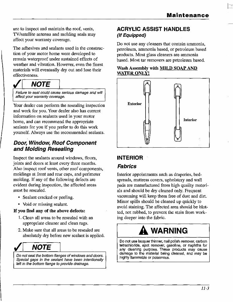
ure to inspect and maintain the roof, vents, TV/satellite antenna and molding seals may affect your wananty coverage.
The adhesives and sealants used in the construction of your motor home were developed to remain waterproof under sustained effects of weather and vibration. However, even the finest materials will eventually dry out and lose their effectiveness.
tff NOTE I Failure to seal could cause serious damage and will affect your warranty coverage.
Your dealer can perform the resealing inspection and work for you. Your dealer also has cunent information on sealants used in your motor home, and can recommend the appropriate sealants for you if you prefer to do this work yourself. Always use the recommended sealants.
Door, Window, Roof Component and Molding Resealing
Inspect the sealants around windows, floors, joints and doors at least every three months. Also inspect roof vents, other roof components, moldings at front and rear caps, and perimeter molding. If any of the following defects are evident during inspection, the affected areas must be resealed.
• Sealant cracked or peeling.
• Void or missing sealant.
If you find any of the above defects:
1. Clean all areas to be resealed with an appropriate cleaner and clean rags.
2. Make sure that all areas to be resealed are absolutely dry before new sealant is applied.
tfr NOTE l Do not seal the bottom flanges of windows and doors. Special gaps in the sealant have been intentionally left in the bottom flange to provide drainage.
Maintenance
ACRYLIC ASSIST HANDLES (If Equipped)
Do not use any cleaners that contain ammonia, petroleum, ammonia based, or petroleum based products. Most glass cleaners are ammonia based. Most tar removers are petroleum based.
Wash Assembly with MILD SOAP AND WATERONLYI
Exterior
INTERIOR
Fabrics
Interior f-
Interior appointments such as draperies, bedspreads, mattress covers, upholstery and wall pads are manufactured from high quality materials and should be dry cleaned only. Frequent vacuuming will keep them free of dust and dirt. Minor spills should be cleaned up quickly to avoid staining. The affected area should be blotted, not rubbed, to prevent the stain from working deeper into the fabric.
A. WARNING Do not use lacquer thinner, nail polish remover, carbon tetrachloride, spot remover, gasoline, or naphtha for any cleaning purpose. These products may cause damage to the material being cleaned, and may be highly flammable or poisonous.
11-3
Maintenance
Solid Surface Top Care (If Equipped)
The counter top is constructed of a solid surface material that requires little care. Routine care involves wiping the surface with a damp cloth to remove water marks. For stains, wipe with soapy water or ammonia-based cleaners. Remove stubborn stains on the "matte/satin" finish with an abrasive cleanser.
Laminate Top Care (If Equipped)
For cleaning laminate surfaces, uses mild dishwashing liquid with warm water. Use a soft cloth for both washing and drying.
Do not use abrasive cleaners, steel wool, or gritty cleaners or damage will·occur to the surface.
Walls and Ceiling Panels
The paneling and the ceiling of your motor home may be any of several finishes and textures. Never use harsh detergents or abrasive cleaners on walls or ceilings. Most surfaces will clean with a soft cloth moistened with mild liquid detergent in warm water, or a clear window cleaner solution. Do not scrub the surface or use large amounts of water which could saturate the material. Simply spray or apply the solution to the spot and blot with a clean dry rag or paper towel. Aggressive scrubbing may damage the texture or pattern.
Attaching Accessories to Your Motor Home
The sidewalls of your motor home are built with a dense fiber and polymer panel or rigid wood panel used as a substrate to the exterior fiberglass or interior finish surface.
Structural members are located specifically to mount and attach factory-installed components and accessories, and may not be located to accommodate after-market accessories not specifically designed for use on or in your motor home.
Exterior: Please consult with your dealer before attempting to install or mount accessories on the
11-4
sidewalls or roof of your motor home. Holes drilled in the sidewall may cause damage, and may affect portions of your warranty.
Interior: If you want to attach items to the interior walls, YOU MUST USE RIVETS. The rivets can be installed with a hand-operated tool such as the Arrow E-Z Pull Model RH200. This and similar tools are available in most hardware stores and home improvement centers.
When you install a component, carefully mark the hole location and drill a 3/16" hole where the rivet is to be located.
If you need rivets, contact your Fleetwood dealer.
CAUTION Do not use any type of screw to attach items to the interior or exterior walls of your motor home. If you want to attach items to the walls, you must use expanding head type rivets. Rivet quantity, length, and grip range, will vary depending on item to be attached.
Plastic/Fiberglass Shower Stall
Some cleaners attack the plastic causing it to discolor and become brittle. The following cleaners have been tested and approved when mixed with water:
• Distilled vinegar
• Mild dishwasher detergent
• Liquid deodorizing cleaner.
Avoid cleaners that contain any amount of abrasives, acetone or MEK (methyl ethyl ketone).
Floors and Carpeting
Vinyl flooring requires only washing and periodic waxing. Vacuum carpeting regularly, and clean it with a quality carpet cleaner. Do not use water or waxes mixed with water on the wood floor.
Wood Floor (If Equipped)
Floors are natural resting places for dust, dirt, grit, and food spills. Dirt underfoot causes abra-
1.be , ,
sions. Therefore, keep the floor clean and use exterior walk off mats at the entry door, and:
• Immediately blot up spills or spots with a damp cloth.
• Periodically clean the floor with Anderson Quick Kleen. Follow the instructions on the container.
Your wood floor can be damaged by a number of things, including:
• Water - Do not wet mop the wood floor • Oil soap or other waxes and polishes • Ammonia cleaners • High heel shoes
Engine Access
The top of the engine may be accessed from inside the motor home for service by lifting or removing the engine cover.
A. WARNING The interior engine cover is heavy. Use care when opening:,or closing the cover.
A. WARNING When installing the engine cover, be sure the cover is fully seated on the gasket seal and secured by the clamps. Do not allow insulation, carpeting, or other material to interrupt the seal between the cover and the engine compartment. If the engine cover is not installed correctly, engine exhaust gases could leak into the passenger compartment creating a safety hazard. If the engine must be run with the engine cover off for maintenance purposes, be sure the vehi-cle interior is adequately ventilated.
EXTERIOR SEALANTS
Consult your Fleetwood Motor Home dealer for the most current sealant use.
Windshield
Window sealant
Roof sealant
Maintenance
GENERATOR FILTERS
Consult your Fleetwood Motor Home dealer or see the Onan Service and Parts Directory in your Owner's Information Package.
Oil Filter
Fuel Pump Filter
Element Fuel Filter
MAINTENANCE GUIDELINE
While many RV owner's use their RV for weekend and vacation travel, others may use their RV full-time. Full-time use of an RV can considerably affect its condition as well as maintenance requirements. As long as you are not full-timing or traveling under several climate conditions, the normal maintenance guidelines that are outlined in your Fleetwood Owner's Manual will ensure your RV will provide you many years of enjoyable use. Severe climates, either hot or cold; can affect your seals, sealants, plumbing, Propane system, and cause internal condensation issues. Full-timing can cause extra wear and tear to your RV, simply from continuous usage and/or extensive miles driven. If you are a full-timer or using your RV in severe climate conditions, follow the "full-timer/severe climate" scheduled maintenance program, as outlines in your Fleetwood Owners Manual. By following this maintenance schedule, you should be able to prolong the life and enjoy your RV for many years to come.
For your convenience, a maintenance guideline is presented. Options and accessories usually have their own owner/user manuals that often contain maintenance instructions. Consult these manuals as required. Modify any suggested maintenance schedule as use conditions or performance requires.
11-5
I---c-~
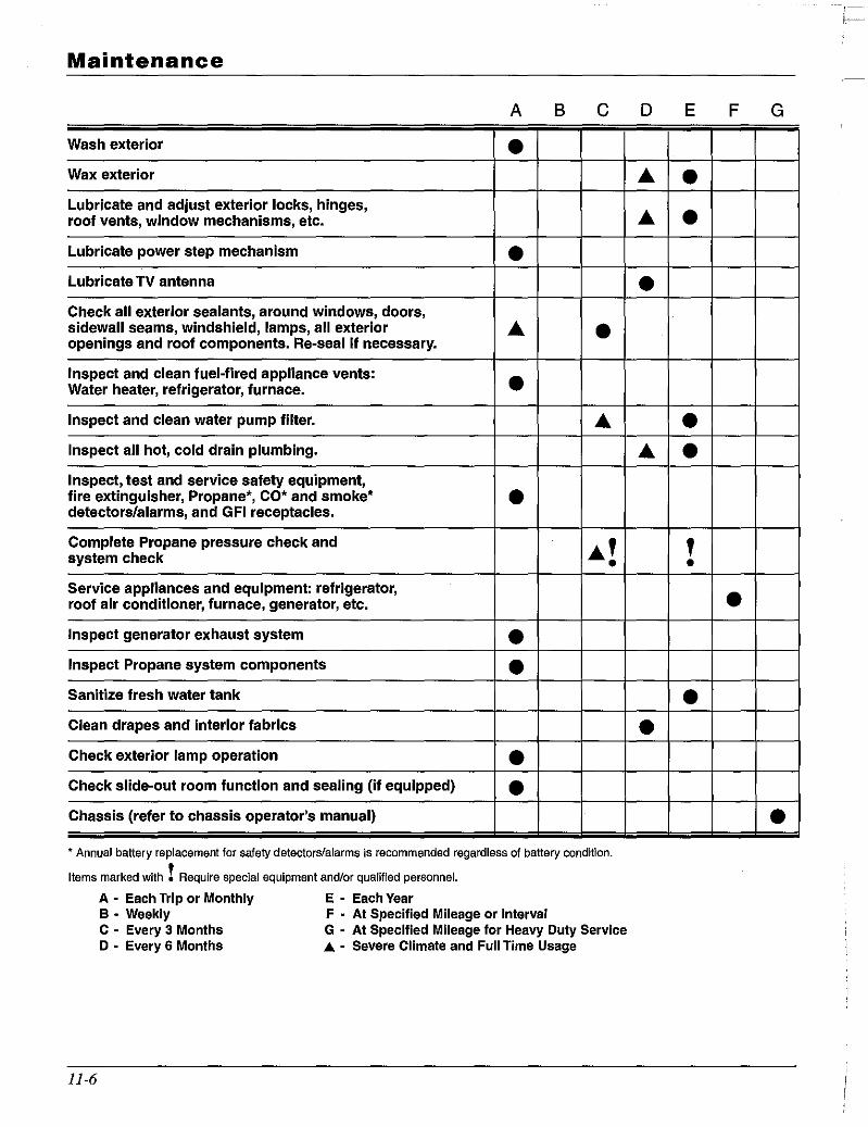
Maintenance
A B c Wash exterior • Wax exterior
Lubricate and adjust exterior locks, hinges, roof vents, window mechanisms, etc.
Lubricate power step mechanism • Lubricate TV antenna
Check all exterior sealants, around windows, doors, sidewall seams, windshield, lamps, all exterior ... • openings and roof components. Re-seal if necessary.
Inspect and clean fuel-fired appliance vents: • Water heater, refrigerator, furnace.
Inspect and clean water pump filter. ... Inspect all hot, cold drain plumbing.
Inspect, test and service safety equipment, fire extinguisher, Propane', CO' and smoke' • detectors/alarms, and GFI receptacles.
Complete Propane pressure check and ... ' system check • Service appliances and equipment: refrigerator, roof air conditioner, furnace, generator, etc.
Inspect generator exhaust system • Inspect Propane system components • Sanitize fresh water tank
Clean drapes and interior fabrics
Check exterior lamp operation • Check slide-out room function and sealing (if equipped) • Chassis (refer to chassis operator's manual)
* Annual battery replacement for safety detectors/alarms is recommended regardless of battery condition.
Items marked With! Require special equipment and/or qualified personnel.
A - Each Trip or Monthly E - Each Year B - Weekly F - At Specified Mileage or Interval C - Every 3 Months G - At Specified Mileage for Heavy Duty Service D - Every 6 Months A - Severe Climate and Full Time Usage
11-6
D E F G
... • ... • •
• ... • , •
•
• •
•
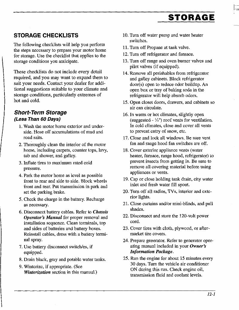
STORAGE CHECKLISTS
The following checklists will help you perform the steps necessary to prepare your motor home for storage. Use the checklist that applies to the storage conditions you anticipate.
These checklists do not include every detail required, and you may want to expand them to suit your needs. Contact your dealer for additional suggestions suitable to your climate and storage conditions, particularly extremes of hot and cold.
Short-Term Storage (Less Than 60 Days)
1. Wash the motor home exterior and underside. Hose off accumulations of mud and road salts.
2. Thoroughly clean the interior of the motor home, including carpets, counter tops, lavy, tub and shower, and galley.
3. Inflate tires to maximum rated cold pressure.
4. Park the motor home as level as possible front to rear and side to side. Block wheels front and rear. Put transmission in park and set the parking brake.
5. Check the charge in the battery. Recharge as necessary.
6. Disconnect battery cables. Refer to Chassis Operator's Manual for proper removal and installation sequence. Clean terminals, top and sides of batteries and battery boxes. Reinstall cables, dress with a battery terminal spray.
7. Use battery disconnect switch/es, if equipped.
8. Drain black, gray and potable water tanks.
9. Winterize, if appropriate. (See Winterization section in this manual.)
STORAGE
10. Turn off water pump and water heater switches.
11. Turn off Propane at tank valve.
12. Turn off refrigerator and furnace.
13. Turn off range and oven burner valves and pilot valves (if equipped).
14. Remove all perishables from refrigerator and galley cabinets. Block refrigerator door(s) open to reduce odor buildup. An open box or tray of baking soda in the refrigerator will help absorb odors.
15. Open closet doors, drawers, and cabinets so air can circulate.
16. In warm or hot climates, slightly open (suggested - '/.") roof vents for ventilation. In cold climates, close and cover all vents to prevent entry of snow, etc.
17. Close and lock all windows. Be sure vent fan and range hood fan switches are off.
18. Cover exterior appliance vents (water heater, furnace, range hood, refrigerator) to prevent insects from getting in. Be sure to remove all covering material before using appliances or vents.
19. Cap or close holding tank drain, city water inlet and fresh water fill spout.
20. Turn off all radios, TV s, interior and exterior lights.
21. Close curtains and/or mini-blinds, and pull shades.
22. Disconnect and store the 120-volt power cord.
23. Cover tires with cloth, plywood, or aftermarket tire covers.
24. Prepare generator. Refer to generator operating manual included in your Owner's Information Package.
25. Run the engine for about 15 minutes every 30 days. Turn the vehicle air conditioner ON during this run. Check engine oil, transmission fluid and coolant levels.
12-1
Storage
Long-Term Storage (Over 60 Days)
1. Perform all steps as required for short-term storage.
2. Run chassis engine to normal operating temperature. Operate automotive air conditioner(s) to lubricate compressor seals. Drain engine oil, replace filter, refill engine with fresh oil.
3. Remove windshield wiper blades and store inside the motor home.
4. Charge and remove both the chassis and house battery(ies). Store in a cool, dry place, and check the charge and water level every 30 days. If the specific gravity is being checked, recharge the battery when it drops to 1.220. With the advent of computer controlled engine and transmission management systems certain procedures must be followed whenever the chassis battery is disconnected or replaced. Please refer to your Chassis Operator's/Owner's Guide/Manual for any instructions supplied by the chassis manufacturer with respect to this subject.
~I NOTE I If your motor home is equipped with a solar battery charger, it will trickle charge the house battery. The battery disconnect switch must be ON for the solar charger to charge the batteries.
5. Remove, clean and replace roof air conditioner filter(s). Cover the air conditioner shroud(s).
6. To help preserve the tires, park each tire on a piece of plywood about 12 inches square.
7. Cover the windows on the inside with foil, cardboard, paper, etc., to reduce curtain, drape, and carpet fading.
8. Remove batteries in battery-powered devices.
12-2
9. During extended periods of storage, gasoline may deteriorate due to oxidation. This can damage rubber and other materials in the fuel system. It may also clog small orifices. Commercially available gasoline fuel stabilizers should be added whenever actual or expected storage periods exceed 60 days. Follow the additive manufacturer's instructions. Operate the vehicle regularly during the storage period to mix and circulate the antioxidant agent throughout the fuel system.
10. Check tire inflation pressures every 30 days. Maintain maximum rated cold inflation pressure.
11. Check the sealant around all roof, floor and body seams and windows. Reseal if necessary. See Sealant Renewal section.
12. Lubricate all locks and hinges as described in the Maintenance chapter.
13. Remove high grass or weed growth if coach is parked on dirt.
WINTERIZATION
Thoughtful planning and preparation for the winter season can help eliminate equipment failures and breakdowns, and can extend the life of your motor home and its systems. Your dealer can advise you concerning specific winterization procedures and products for your climate area or the areas through which you will be traveling. Your dealer may also provide winterization service for all appliances and systems in the motor home. The following is a check list if you prefer to perform these procedures yourself:
1. Check engine coolant level and antifreeze protection. Drain and flush engine cooling system and add antifreeze per the chassis operator's manual.
2. Service and winterize the generator as outlined in the generator operating manual included in your Owner's Information Package.
3. Winterize the Propane system. Your Propane dealer or service station will perform this for you.
4. Winterize all appliances as outlined in the individual operator's manuals.
5. Remove snow accumulations as often as possible.
Water System Winterizing
Read this section completely before performing winterization.
CAUTION Draining the water system alone will not provide ade-quate cold weather protection. If the motor home is to be unheated during below freezing temperatures, consult your dealer for the best winterizing procedure for your climate. Your dealer can winterize your motor home for you or can supply you with one of the spe-cial antifreezes which are safe and approved for use in RV water systems. Follow the instructions furnished with the antifreeze.
A WARNING Do not use automotive or windshield washer anti-freeze in the motor home water system. These solu-tions may be harmful if swallowed.
1. Remove water filter cartridge, if equipped, and install the winterizing adapter.
2. Drain the fresh water tank by opening the water tank drain valve. Close valve when drained.
3. Turn water pump on (12-volt power must be on).
4. Open a cold water faucet. When the flow of water stops, turn the pump off.
5. Open water faucets, then open the drain valves on HOT and COLD water pipes. Leave these valves open.
6. Drain the water heater by opening the drain plug at the bottom of the heater and the safety valve at the top.
Storage
7. Flush the toilet. Operate toilet sprayer, if equipped.
8. Drain the shower head by opening the valve. Let all water drain out the tub spout. Leave the valve open.
9. When each faucet has been drained, close all faucets, water line drain valves and the fresh water tank drain valve, install the water heater plug and close the safety valve.
10. Drain the waste water system by following the normal procedure for draining the holding tanks. (See Plumbing chapter).
11. Apply silicone lubrication to the knife valve actuator rod(s).
12. Be sure ALL water from ALL plumbing fixtures has been drained.
13. Close holding tank drain valves.
14. Pour approximately five gallons of approved non-toxic antifreeze into the fresh water tank.
15. Turn the water pump master switch ON.
16. Open each water faucet, run the water pump and let about a cup of antifreeze solution flow continuously through each faucet. Close each water faucet.
17. Flush the toilet until the antifreeze solution flows continuously. Release flush mechanism.
18. Your vehicle is equipped with a water heater bypass. Winterize the hot water lines by opening each hot water faucet, allowing antifreeze solution to flow continuously, and then close each faucet. This will require considerably more antifreeze solution, and you may choose to do this step before winterizing the cold water lines so you can recycle the solution.
v"1 NOTE I When filling the plumbing systems with antifreeze, be sure to open and operate aI/ fixtures and valves aI/owing the antifreeze solution to flow freely.
12-3
Storage
19. Pour one cup of antifreeze solution down each drain.
20. Install all protective caps: Water tank fill City water inlet cap Waste tank drain outlet cap
21. If your refrigerator is equipped with an ice maker, winterize it as follows:
1. Shut off the water supply valve to the ice maker.
2. Place a shallow pan under the water solenoid valve.
3. Remove the inlet fitting to the ice maker water solenoid valve. Drain the water from the supply ·line.
4. Remove the plastic nut and water line from the outlet side of the water solenoid valve. Drain water from the line.
5. Cycle the ice maker several times while blowing compressed air through the water solenoid valve. Be sure all water is out of the solenoid. NOTE: Your motor home dealer can do this for you.
6. Reconnect and tighten the lines on the solenoid valve. Leave the water supply turned off until temperatures are above 32°FlOoC.
7. Dry out the ice maker mold assembly with a soft cloth. Place the bail arm to the UP/OFF position.
REACTIVATING THE MOTOR HOME AFTER STORAGE
If the motor home was properly and carefully prepared for storage, taking it out of storage will not be difficult. The following procedure check list assumes that you stored the motor home with care. If you didn't, and extensive freeze damage or other serious deterioration has occurred, please consult your dealer or an authorized Fleetwood Dealer for advice.
12-4
1. Thoroughly inspect the outside of the vehicle. Look for animal nests in wheel wells, under the hood, in air cleaner or in other out of the way places.
2. Remove all appliance vents, ceiling vent and air conditioner coverings. Be sure all furnace, water heater, and refrigerator openings are clear and free of debris or insect nests, webs, etc.
3. Open all doors and compartments. Check for animal or insect intrusion, water damage, or other deterioration.
4. Check all chassis fluid levels - engine oil, engine coolant, power steering fluid, brake fluid, transmission fluid, rear axle oil.
5. Check charge level in batteries. Refill and recharge as necessary. Reinstall batteries if necessary. Be sure cable ends and terminals are clean and free of corrosion. Check Chassis Operator's/Owner's Guide/Manual for any instructions on resetting chassis computer after battery is reinstalled.
6. Check tire pressures. Inflate to specified cold pressure.
7. Remove covering from inside windows.
8. Open vents and windows for ventilation.
9. Be sure engine instruments indicate proper readings. Run engine up to operating temperature. Shut engine down. Check all fluids. Top up if necessary.
10. During engine run, check the operation of headlights, tail-lights, tum signals, backup lights, clearance lights, license plate light, emergency flashers. Operate the vehicle air conditioner. If air conditioner does not work, or unusual sounds occur, have the system checked by a qualified air conditioner technician.
11. Drain, flush, and sanitize the fresh water system as outlined in the Plumbing chapter.
12. Install a new water filter cartridge (if equipped).
1= !
I
\
13. Operate all faucets and fixtures in the fresh water system. Check for leaks at all joints and fittings. Repair if necessary making sure the water heater bypass is open.
14. Check operation of 12-volt circuit breakers and inspect fuses. Replace as necessary.
15. Operate all12-volt lights and accessories.
16. Install new batteries in battery-operated devices. Check operator's manual for each device for any additional requirements.
17. Test carbon monoxide, Propane and smoke detectors/alarms.
18. Check monitor panel operation.
19. Operate vents and vent fans, including the range hood fan.
20. Inspect the 120-volt electrical systempower cord, converter, all outlets, and any exposed wiring. If defects are found, refer service to your dealer or an authorized Fleetwood Dealer.
21. Prepare the generator for operation following instructions in the generator operating manual in your Owner's Information Package.
22. Start and run generator.
23. Operate 120-volt appliances and air conditioner(s). Be sure to uncover air conditioner shroud(s).
24. Inspect the Propane system and check for leaks as described in the Propane System chapter. If the Propane tank shows signs of rust or corrosion, have it inspected by a qualified Propane technician.
Storage
25. Operate each Propane appliance. Have the Propane regulator adjusted for proper pressure by a qualified technician.
26. Inspect and clean the interior.
27. Check the sealant around all roof, floor and body seams and windows. Reseal if necessary. See Sealant Renewal section.
28. Lubricate all exterior locks, hinges, and latches.
29. Reinstall windshield wiper blades or remove protective covers. Check wiper/washer operation.
30. Wash and wax the exterior. Inspect the body for scratches or other damage. Touch up or repair as necessary. Flush the underside thoroughly.
31. Run thorough operational checks of steering, brakes, engine and transmission. Operate vehicle slowly during these checks to allow sufficient circulation of fluids and reseating of components.
Your motor home should now be ready for a new traveling season. If you choose, your dealer can double check your preparation and repair any problems or make any necessary adjustments.
12-5

f
f
This page intentionally blank.
\
\
=-~------
AC Inverter - An electronic device that changes 12-volt DC energy from the batteries to 120-volt 60-cy cle, AC energy to operate microwave ovens, TVs, VCRs, or other appliances that require 120-volt 60-cycle power.
Belted Seating Positions - These are seats with seat belts. Anyone riding in the motor home must use one of these seats any time the motor home is in motion.
Black Water Tank - The water tank in your plumbing system that is designed to contain waste water from the toilet ONLY.
CCC (Cargo Carrying Capacity) - Is equal to GVWR minus each of the following: UVW, full fresh (potable) water weight (including water heater), full Propane weight and SCWR.
CAUTION - Any statement in this Owner's Manual that, if not followed, could result in damage to the vehicle or components.
Chassis Operator's/Owner's Guide/Manual -This is the operating and maintenance manual supplied by the chassis manufacturer. It is part of your Owner's Information Package. It contains information on operating and maintaining the engine, transmission, drivetrain and other components of the motor home chassis.
Clearance Lights - This switch will flash the clearance lights and is useful when signalling other large vehicles when passing or being passed.
DC Converter - An electronic device that changes l20-volt AC energy from the main power connection or the generator to 12-volt DC energy to operate the l2-volt interior lights or other 12-volt DC appliances or accessories.
Designated Seating Capacity (Canadian units only) - The number of sleeping positions des-
GLOSSARY
ignated equals the seating capacity.
Dinghy - A motorized vehicle, such as an automobile or truck towed behind a motor home with all four tires on the ground.
Doorside - The right side of the motor home from the driver's point of view. So named because the main entry/exit door is on this side.
FIN (Fleetwood Identification Number) - This is the number that identifies your motor home as a Fleetwood product. Use this number when ordering parts or requesting warranty service for your motor home.
GAWR (Gross Axle Weight Rating) - The maximum permissible loaded weight a specific axle is designed to carry.
GCWR (Gross Combined Weight Rating) - The value specified by the motor home manufacturer as the maximum allowable loaded weight of this motor home with its towed trailer or towed vehicle. Towing and braking capacities may be different. Refer to Fleetwood and the chassis manufacturer's manuals for complete information.
Gear Preselection - The selection of a lower gear to match the driving conditions you encounter or expect to encounter. Preselection will give you better control on slick or icy roads and on downgrades. Downshifting to lower gears increases engine braking. The selection of a lower gear often prevents cycling between a gear and the next higher gear on a series of short up-and-down grades.
GFCI (Ground Fault Circuit Interrupter) - An electrical device attached to the bathroom AC circuits that disconnect the outlet if a problem occurs in the ground circuit.
Gray Water Tank - The water tank in your plumbing system that is designed to contain waste water from the sinks and shower drains ONLY. No toilet wastes go into this tank.
13-1
1---
I ~ __
Glossary
GTW (Gross Towing Weight) - Is the maximum loaded weight of a trailer or car this motor home, with equipped hitch, has been designated to tow. GTW cannot be increased by changing the trailer hitch.
GVWR (Gross Vehicle Weight Rating) - Is the maximum permissible weight of this fully loaded motor home. The GVWR is equal to or greater than the sum of the Unloaded Vehicle Weight plus the Cargo Carrying Capacity.
Hitch Rating - Means the maximum allowable weight of a towed trailer or towed vehicle. The GCWR of the motor home must never be exceeded, even if the weight of the towed trailer or towed vehicle is less than the hitch rating.
Monitor Panel - An electronic device that allows you to conveniently measure the approximate levels in the fresh water, gray and black water tanks. You can also check the charge in the batteryibatteries.
MTW (Maximum Tongue Weight) - Is the maximum permissible downward force exerted on the hitch ball by the towed vehicle coupler.
NOTE - A statement or instruction in this Owner's Manual with information to help you use the vehicle or equipment more efficiently, such as a tip.
Owner's Information Package - This is a package of papers, manuals, warranty and instruction cards, and other material put together for you by Fleetwood. These materials contain operating and maintenance instructions for most of the components and appliances in your motor home.
Ownercare Card - The card that has your name and vehicle ill (FIN) embossed on it. Use this card when you request or need warranty service. Please note that this is NOT a credit card. You cannot purchase anything with it. It is used only to identify you and your motor home.
13-2
Park Cable - The F-style video connector that allows you to connect to an outside television signal source, such as the cable TV feed at an RV park, or any other 75-ohm video source. This connector usually carries an RF modulated signal.
Park/City Water Connection - The "gardenhose" style connector that allows you to connect to an outside pressurized water source.
Power/Shore Cord - This is the main power cord coming into your motor home electrical system. You connect it to l20-volt AC power at a park or campsite.
Roadside - The left side of the motor home from the driver's point of view. So named because, at least in North America, the "road" outside the vehicle is usually on this side.
SCWR (Sleeping Capacity Weight Rating) - Is the manufacturer's designated number of sleeping positions multiplied by 154 pounds (70 kilograms).
MTW (Maximum Tongue Weight) - The maximum permissible downward force exerted on the hitch ball by the towed vehicle coupler.
UVW (Unloaded Vehicle Weight) - The weight of the motor home, as built at the factory with full fuel, engine oil and coolants. The UVW does not include cargo, fresh water, Propane, occupants or dealer installed accessories. Note: Canadian UVW includes designated seating, Propane and water.
VIN (Vehicle IdentifICation Number) - The legal, 17 -digit vehicle identification number as shown on the vehicle registration certificate.
WARNING - A statement or instruction in this Owner's Manual that, if not followed, could lead to personal injury or death.