Embed Size (px)
Citation preview

2007-05-07
Tian-Wei Huang–NTUSlide 1
doc.: IEEE 802.15-07/0692r0
TG3c Presentation
Project: IEEE P802.15 Working Group for Wireless Personal Area NProject: IEEE P802.15 Working Group for Wireless Personal Area Networks (WPANs)etworks (WPANs)
Submission Title: [Dual-Mode Broadband and Wireless Network (DMBWN)]Date Submitted: [07 May, 2007]Source: [Ching-Kuang Tzung, Ta-Sung Lee*, Jenn-Hwan Tarng*, Yu-De Lin*, Fu-Chiang Chen*, Chi-Hsueh Wang, Tian-Wei Huang, Huei Wang, Shih-Yuan Chen, Powen Hsu, Tah-Hsiung Chu, Ruey-Beei Wu, and Chun-Hsiung Chen ] Company [Department of Electrical Engineering, National Taiwan University, * National Chiao Tung University, Hsin-Chu, Taiwan, ]Address [No.1, Sec. 4, Roosevelt Road, Taipei 10617, Taiwan, R.O.C. ]Voice:[+886 2 2363 3289], FAX: [+886 2 2368 3824 ], E-Mail:[[email protected]]Re: []
Abstract: [Description of the concept of Dual-Mode Broadband and Wireless Network]Purpose: [Contribution to TG3c at May 2007 meeting.]Notice: This document has been prepared to assist the IEEE P802.15. It is offered as a basis for discussion and is not binding on the contributing individual(s) or organization(s). The material in this document is subject to change in form and content after further study. The contributor(s) reserve(s) the right to add, amend or withdraw material contained herein.Release: The contributor acknowledges and accepts that this contribution becomes the property of IEEE and may be made publicly available by P802.15.

2007-05-07
Tian-Wei Huang–NTUSlide 2
doc.: IEEE 802.15-07/0692r0
TG3c Presentation
Dual-Mode Broadband and Wireless Network (DMBWN)
Ching-Kuang Tzung, Ta-Sung Lee*, Jenn-Hwan Tarng*, Yu-De Lin*, Fu-Chiang Chen*, Chi-Hsueh Wang, Tian-Wei Huang, Huei
Wang, Shih-Yuan Chen, Powen Hsu, Tah-Hsiung Chu, Ruey-Beei Wu, and Chun-Hsiung Chen
National Taiwan University*National Chiao Tung University
May 07, 2007

2007-05-07
Tian-Wei Huang–NTUSlide 3
doc.: IEEE 802.15-07/0692r0
TG3c Presentation
Dual-Mode Broadband and Wireless Network (DMBWN): a backward
compatible system concept
AP
MT1
60GHz
60GHz
60GHz
60GHz5GHz
5GHz
5GHz
MT2
MT3
5GHz
RF front-end architecture for 5GHz / 60GHz RF signal transmission/reception
Smart antenna array based on switched beamforming

2007-05-07
Tian-Wei Huang–NTUSlide 4
doc.: IEEE 802.15-07/0692r0
TG3c Presentation
Motivation & Overview• Long Range: lower operation frequency for communicating
long-distance terminals. • Backward Compatible System: the baseband realization
is highly compatible with the OFDM based IEEE 802.11a/n standard.
• 5-GHz band, – Infrastructure mode – MIMO-OFDM technique is adopted to improve the performance
• 60-GHz band, – ad-hoc mode – Single -Carrier with Frequency-Domain Equalization (SC-FDE)
strategy combined with switched beamforming for interference suppressing

2007-05-07
Tian-Wei Huang–NTUSlide 5
doc.: IEEE 802.15-07/0692r0
TG3c Presentation
•Switched beam / DOA estimation
•60G (Ad-hoc) / 5 G (Infrastructure) selector
•60G / 5 G ; TX / RX switch
•LO1 / LO2 band selectors
•TX power attenuator setting
Passive RF Circuits
Active RF Circuits
BB Modules
Digital Control Lines
Analog Signal Lines
60/5 GHz Dual-Mode Wireless Network Station
Sw
itched B
eamform
er
PA
LNA
60 GHz
BPF
BPF
BW=3 GHz
BW=3 GHz
PA
LNA5 GHz
A/D
s&D/A
s
Existing
5 GH
zTransceiver
B1~B4
LO1BPF
BPF
BW=200 MHz
ATT.
Amp BPF
Amp
Amp
LO2
53.85~56.65 GHz
FrequencyReference
To A1~A4
From B1~B4
CO
M
DIVAmp
Amp
59~62 GHz
5.15~5.35 GHz
Baseband
&M
AC
/DL
C
BW=200MHz
5.18~5.32 GHz
A1~A4

2007-05-07
Tian-Wei Huang–NTUSlide 6
doc.: IEEE 802.15-07/0692r0
TG3c Presentation
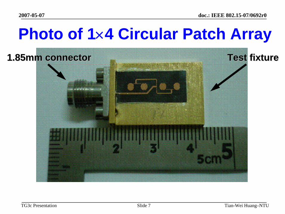
60-GHz Switched-Beam Antenna • 60-GHz switched-beam antenna array has
been developed in National Taiwan University– Linear polarization circular polarization– 4 elements 8 elements
2007-05-07
Tian-Wei Huang–NTUSlide 7
doc.: IEEE 802.15-07/0692r0
TG3c Presentation
Photo of 1×4 Circular Patch Array1.85mm connector1.85mm connector Test fixtureTest fixture

2007-05-07
Tian-Wei Huang–NTUSlide 8
doc.: IEEE 802.15-07/0692r0
TG3c Presentation
Radiation Patterns (1×2 array)
xx--zz planeplane yy--zz planeplane60.5 GHz60.5 GHz

2007-05-07
Tian-Wei Huang–NTUSlide 9
doc.: IEEE 802.15-07/0692r0
TG3c Presentation
Radiation Patterns (1×4 array)
xx--zz planeplane yy--zz planeplane60.5 GHz60.5 GHz

2007-05-07
Tian-Wei Huang–NTUSlide 10
doc.: IEEE 802.15-07/0692r0
TG3c Presentation
In-Band Peak Gains
11××2 array2 array 11××4 array4 arrayRHCPRHCP

2007-05-07
Tian-Wei Huang–NTUSlide 11
doc.: IEEE 802.15-07/0692r0
TG3c Presentation
2007-03-13
Tian-Wei Huang–NTUSlide 11
60GHz DPQT Switch
0.15 mm PHEMT , DPQT SwitchLow insertion loss at 60GHzHigh isolation

2007-05-07
Tian-Wei Huang–NTUSlide 12
doc.: IEEE 802.15-07/0692r0
TG3c Presentation
A 0.13μm CMOS 60-GHz Transceiver
Low power consumption (97mW)Tx Pout = -2dBm, IQ ModulationMiniature chip size, and Low CostLow Cost
C-H. Wang, H-Y. Chang, P-S. Wu, K-Y. Lin, T-W. Huang, H. Wang, C-H. Chen, "A 60GHz Low-Power Six-Port Transceiver for Gigabit Software-Defined Transceiver Applications,” 2007 International Solid-State Circuit Conference (ISSCC), San Francisco, CA, Feb. 2007.
Tx High Gian Mode
Rx: 4Gbps BPSK

2007-05-07
Tian-Wei Huang–NTUSlide 13
doc.: IEEE 802.15-07/0692r0
TG3c Presentation
25-75 GHz 90nm CMOS Gilbert-cell MixerProcess : 90nm CMOSTopology : Gilbert-cell Chip size: 0.55 mm × 0.55 mm RF Frequency : 25-75 GHz
Conversion Gain : 3 ± 2 dBLO Driver Power : 6 dBmPower Consumption : 93 mWIsolation : 30 dB
Jeng-Han Tsai, Pei-Si Wu, Chin-Shen Lin, Tian-Wei Huang, John G.J. Chern, and Wen-Chu Huang, " A 25-75-GHz Broadband Gilbert-cell Mixer Using 90-nm CMOS Technology," IEEE Microwave and Guided Wave Letters, April 2007.

2007-05-07
Tian-Wei Huang–NTUSlide 14
doc.: IEEE 802.15-07/0692r0
TG3c Presentation
60-GHz Transmitter with Integrated Antenna
Chi-Hsueh Wang, Yi-Hsien Cho, Chin-Shen Lin, Huei Wang, Chun-Hsiung Chen, Dow-Chih Niu, John Yeh, Chwan-Ying Lee, and John Chern,“A 60-GHz transmitter with integrated antenna in 0.18-mm SiGe BiCMOS technology,” 2006 International Solid-State Circuit Conference (ISSCC), San Francisco, CA, Feb. 2006.
• Technology: 0.18-μm SiGe BiCMOS process• Chip size: 1.3 x 0.8 mm2
• Conversion gain: 20.2 dB• Output power: 15.8 dBm• DC power consumption: 281 mW

2007-05-07
Tian-Wei Huang–NTUSlide 15
doc.: IEEE 802.15-07/0692r0
TG3c Presentation
60-GHz Single Carrier Baseband (1)
FECCoding Mapper
AddGuard Interval
Upsampler&
RRCDAC
ADCTime-SyncFreq-Sync
Ch. EstFFT
Freq.Domain
Eq.IFFTPhase
TrackingDe-
mapperViterbi
Decoding
BinaryInputData
BinaryInputData
FECCoding Mapper
AddGuard Interval
Upsampler&
RRCDAC
ADCTime-SyncFreq-Sync
Ch. EstFFT
Freq.Domain
Eq.IFFTPhase
TrackingDe-
mapperViterbi
Decoding
BinaryInputData
BinaryInputData
Diagrammatical description of the SC-FDE system.

2007-05-07
Tian-Wei Huang–NTUSlide 16
doc.: IEEE 802.15-07/0692r0
TG3c Presentation
60-GHz Single Carrier Baseband (1)
EncoderDataChannel
Mapper
Guard Interval
PreambleGenerator
MUX Upsample&
RRCDAC
Diagrammatical description of the SC-FDE transmitter

2007-05-07
Tian-Wei Huang–NTUSlide 17
doc.: IEEE 802.15-07/0692r0
TG3c Presentation
60-GHz Single Carrier Baseband (2)
Diagrammatical description of the SC-FDE receiver
FrequencySynchronization
FrequencyOffset Estimation
FFTFrequency
Domain Equalization
ChannelEstimation
IFFT
Carrier PhaseOffset
Compensation
Carrier PhaseOffset Estimation
Demapper ViterbiDecoder
Timing Synchronization
Frequency Synchronization Channel Equalization
Phase Tracking
Preamble
OutputData
Match Filter
SymbolTiming
Recovery
PacketDetection
Slicer
2007-05-07
Tian-Wei Huang–NTUSlide 18
doc.: IEEE 802.15-07/0692r0
TG3c Presentation
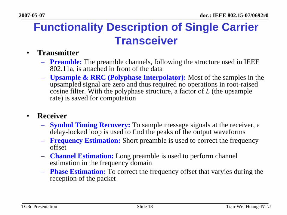
Functionality Description of Single Carrier Transceiver
• Transmitter– Preamble: The preamble channels, following the structure used in IEEE
802.11a, is attached in front of the data – Upsample & RRC (Polyphase Interpolator): Most of the samples in the
upsampled signal are zero and thus required no operations in root-raised cosine filter. With the polyphase structure, a factor of L (the upsamplerate) is saved for computation
• Receiver– Symbol Timing Recovery: To sample message signals at the receiver, a
delay-locked loop is used to find the peaks of the output waveforms– Frequency Estimation: Short preamble is used to correct the frequency
offset– Channel Estimation: Long preamble is used to perform channel
estimation in the frequency domain– Phase Estimation: To correct the frequency offset that varyies during the
reception of the packet

2007-05-07
Tian-Wei Huang–NTUSlide 19
doc.: IEEE 802.15-07/0692r0
TG3c Presentation
Parameters of Single Carrier Transceiver
Number of frames/packet 6
Number of total symbols/frame 64
Number of data symbols/frame (NS) 48
Number of Guard Interval symbols/frame (NG) 16
FFT Size 64
Long Preamble Size (symbols) 64+16 (CP)
Short Preamble Size (symbols) 16
Modulation Schemes QPSK
Coding Rates 1/3
Pulse Shaping RRC (α=0.25)

2007-05-07
Tian-Wei Huang–NTUSlide 20
doc.: IEEE 802.15-07/0692r0
TG3c Presentation
Performance of Single Carrier Receiver

2007-05-07
Tian-Wei Huang–NTUSlide 21
doc.: IEEE 802.15-07/0692r0
TG3c Presentation
60-GHz Single Carrier Baseband HW Architecture (1)
add_GI
din_Idin_Q
rdy_in_Irdy_in_Q
clkrst
dout_Idout_Q
rdy_out_Irdy_out_Q
pkt_fin_Ipkt_fin_Q
d_Id_Q
dri_Idri_Q
df_Idf_Q
p_Ip_Q
pri_Ipri_Q
pf_Ipf_Q
dout_Idout_Q
rdy_out_Irdy_out_Q
mux
44
44
444
88
clkrst
clkrst
dinrdy_in
dout
rdy_out
Convclkrst
din
rdy_in
dout_Idout_Q
rdy_out_Irdy_out_Q
mapper
prmb
trigger_Itrigger_Q
clkrst
pout_Ipout_Q
rdy_out_Irdy_out_Q
finish_Ifinish_Q
upsample_RRC
dout_Idout_Q
rdy_out_Irdy_out_Q
RFD
dout_Idout_Q
clkrst
System ClockAsynchronized Reset
• Transmitter

2007-05-07
Tian-Wei Huang–NTUSlide 22
doc.: IEEE 802.15-07/0692r0
TG3c Presentation
60-GHz Single Carrier Baseband HW Architecture (2)
• Receiver
1414
de_map
pkt_detclkrst
din_Idin_Q
dout_Idout_Q
rdy_in rdy_out
mfclkrst
din_Idin_Q
dout_Idout_Q
rdy_in rdy_out
dllclkrst
din_Idin_Q
dout_Idout_Q
rdy_in rdy_out
ln_pmb_cp_rmclkrstdin_Idin_Q
rdy_in
dout_Idout_Q
rdy_out
freq_compphase_in
din_Idin_Q
rdy_in
dout_Idout_Q
rdy_out
ph_compdin_Idin_Qrdy_in
dout_Idout_Qrdy_out
FFTclkrst
din_Idin_Q
rdy_in
XK_REXK_IM
fft_dv
DOUT_RE
rdy_out_DDOUT_IM
ch_eq
acc_XS_REacc_XS_IMrdy_out_PMB
DIN_REDIN_IMrdy_out_D
clkrst
ch_estclkrst
acc_XS_REacc_XS_IM
rdy_out_PMB
DOUT_REDOUT_IMrdy_out_D
XK_REXK_IM
fft_dv
IFFTclkrst
dout_Qdout_I
rdy_out
XK_RE
rdy_inXK_IM
clkrst
din_Idin_Qrdy_in
doutrdy_out
viterbiclkrst
doutrdy_out
dinrdy_in
freq_est
rst
din_Idin_Q phase
rdy_intriggersw_st_pmb
clkrst
sout_Isout_Q
rdy_out_s
din_Idin_Q
rdy_in
dout_Idout_Q
rdy_out
ren
Timing Synchronization
Frequency Offset Compensation
Frequency Domain Equalization Phase Offset Compensation
88
88
1111
1111
1111 14
1111
1414
14
14
14
1414
1414
1414
1414
ph_err_estdin_Idin_Qrdy_in
phaseph_I
ph_Qrdy_out
1414

2007-05-07
Tian-Wei Huang–NTUSlide 23
doc.: IEEE 802.15-07/0692r0
TG3c Presentation
5 GHz MIMO-OFDM Transceiver Architecture
• Transmitter
• Receiver PreambleChannel
IFFTS/P P/S MUX/RRC
S:STBCL:None
Encoder Inter-leaver Mapper DEMUX
DataChannel
Group-Wise
ST-BlockCoding
VBLAST
Group-Wise
Decoder
ST-Block
Decoder
RRC FFT
Preamble
TimeSynchronization
ChannelEstimation
PhaseEstimation
De-Mapper
De-Inter
leaver
ViterbiDecoder
OutputData
FrequencyEstimation
Pilot Subcarrier

2007-05-07
Tian-Wei Huang–NTUSlide 24
doc.: IEEE 802.15-07/0692r0
TG3c Presentation
Functionality Description of MIMO-OFDM Transceiver (1)
• Transmitter– Channel Encoder : Using the convolution code for error
correction– Interleaver : The transmitted information is better resistant to the
channel distortion by distributing the same coded bits into different positions in the packet
– A MIMO system is typically designed to meet two different, yet opposite, targets: • High spectral efficiency (Spatial Multiplexing) : VBLAST• Reliable transmission (Spatial Diversity) : Space-time block codes
(STBC)– Preamble : The preamble channels, coded by the rule of STBC,
will be attached in front of the data channel modulated by IFFT

2007-05-07
Tian-Wei Huang–NTUSlide 25
doc.: IEEE 802.15-07/0692r0
TG3c Presentation
Functionality Description of MIMO-OFDM Transceiver (2)
• Receiver– Time Synchronization : To find out where the symbol boundaries
are and what the optimal timing instants are to minimize the effects of inter-symbol-interference (ISI) and inter-carrier-interference (ICI)
– Frequency Estimation : To correct the frequency offset, which is caused by the difference of oscillator frequencies at the transmitter and the receiver
– Channel Estimation : Owing to the same symbol structure as data symbols, long preamble becomes the best candidate for performingthis job
– Phase Estimation : To correct the frequency offset that varyiesduring the reception of the packet
– Space-Time Block Decoder : Decode the data with diversity gain
– VBLAST Decoder : Decode the data with multiplexing gain

2007-05-07
Tian-Wei Huang–NTUSlide 26
doc.: IEEE 802.15-07/0692r0
TG3c Presentation
Parameters of MIMO-OFDM Transceiver
{-21, -7, 7, 21}Locations of Pilot Tones
{-32:-27, 0, 27:31}Locations of Zero Tones
{-26:-22, -20:-8, -6:-1,1:6, 8:20, 22:26}Locations of Data Tones
16Short Preamble Size
64+16 (CP)Long Preamble Size
64 {-32:31}FFT Size
4Number of Pilot Tones / Symbol
12Number of Zero Tones / Symbol
48Number of Data Tones / Symbol
6Number of OFDM Symbols / Packet
10Number of Short Preambles / Packet
2Number of Long Preambles / Packet
2Number of Receive Antennas
2Number of Transmit Antennas

2007-05-07
Tian-Wei Huang–NTUSlide 27
doc.: IEEE 802.15-07/0692r0
TG3c Presentation
Performance of MIMO-OFDM Receiver

2007-05-07
Tian-Wei Huang–NTUSlide 28
doc.: IEEE 802.15-07/0692r0
TG3c Presentation
5-GHz MIMO-OFDM Baseband HW Architecture (1)
• Transmitter
clk
data_in
RST
data_out
wen
clkdata_in
RST
data_i_1data_i_2
data_q_1data_q_2
wen
mapperclkmod_even_imod_odd_imod_even_qmod_odd_qRST
ant1_iant1_qant2_i
ant2_qwen
delay_1clk
2222
delay_1clk
22
clkDI_inDQ_inRST
ifft_i_outifft_q_out
clkdata_i_indata_q_inRST
os_cp
data_i_outdata_q_out
wen
clkRST
pmb_gen_tx1pmb_i
pmb_q
sel
w2_iw2_q
w1_iw1_q
f_i
f_q
pmb_data_mux
D_inRST
RRCRRC_out
D_inRST RRC_out
22 10 10
10
10
10
1010
1010
clkDI_inDQ_inRST
ifft_i_outifft_q_out
clkdata_i_indata_q_inRST
data_i_outdata_q_out
wen
clkRST
pmb_gen_tx2pmb_i
pmb_q
sel
w2_iw2_q
w1_iw1_q
f_i
f_q
D_inRST
RRCRRC_out
D_inRST RRC_out
22 1010
10
10
10
1010
1010
delay_1clkdelay_90clk
TX1
TX2
clk
data_in
RSTencode
wen
interleaverSTBC(demux)
+pt_ztconv
delay_1clk
IFFT
os_cp pmb_data_muxIFFT

2007-05-07
Tian-Wei Huang–NTUSlide 29
doc.: IEEE 802.15-07/0692r0
TG3c Presentation
5-GHz MIMO-OFDM Baseband HW Architecture (2)
• Receiver
RX1
RX2
D_inRST
rx_rrc
RRC_out
D_inRST RRC_out
D_inRST RRC_out
D_inRST RRC_out
clkrx1_i_in
rx1_q_in
rx2_i_in
rx1_q_inRST
frm_str
time_sync
RST data_i_indata_q_inclk
rm_os+rm_cp
data_i_outdata_q_out
wen
clkDI_inDQ_inRST
FFT
ifft_i_outifft_q_out
clkdata_i_indata_q_inRST
mv_pt_ztdata_even_i_out
data_even_q_outdata_odd_i_out
data_odd_q_outwen
10
10
11
11 14
RST data_i_indata_q_inclk
rm_os+rm_cp
data_i_outdata_q_out
wen
clkDI_inDQ_inRST
FFT
ifft_i_outifft_q_out
clkdata_i_indata_q_inRST
mv_pt_zt11 14
14
11
11
delay_90clk
data_delay_43clk
data_even_i_outdata_even_q_out
data_odd_i_outdata_odd_q_out
wen
14
rx1_data_even_irx1_data_even_qrx1_data_odd_irx1_data_odd_qrx2_data_even_irx2_data_even_qrx2_data_odd_irx2_data_odd_q
rst
ch_estH11_i
H11_qH21_i
H21_qH12_i
H12_qH22_i
H22_q
ph_estrx1_phi_even_i
rx1_phi_even_qrx1_phi_odd_i
rx1_phi_odd_qrx2_phi_even_i
rx2_phi_even_qrx2_phi_odd_i
rx2_phi_odd_q
H11_iH11_qH21_iH21_qH12_iH12_qH22_iH22_qrx1_data_even_irx1_data_even_qrx1_data_odd_irx1_data_odd_qrx2_data_even_irx2_data_even_qrx2_data_odd_irx2_data_odd_qrst
14
12
14
12
lnpmb_fft_rom
z1_even_iz1_even_qz1_odd_iz1_odd_q
z2_even_iz2_even_qz2_odd_iz2_odd_q
H phi
data_delay_22clk
delay_53clk
rst
delay_4clk
de_map
wen
delay_1clk
data_in
rst
data_out
wen rst
delay_1clk
data_indata_out
wen
de_STBC(VBLAST)de_map
de_leav viterbidecoder

2007-05-07
Tian-Wei Huang–NTUSlide 30
doc.: IEEE 802.15-07/0692r0
TG3c Presentation
• Transmitter
• Receiver
High Throughput MIMO-OFDM Technique
S/PS/P IFFTIFFTM Short
CPShortCP
Ant 1M-QAMSymbols
DEMUXDEMUX MBit →M-QAMBit →
M-QAMInformation
BitsInformation
Bits
S/PS/P IFFTIFFTM Short
CPShortCP
Ant NM-QAMSymbols
M M
Reduce CP Length to Increase ThroughputAnt 1
Ant MStackingStackingM
Matched Filter
Matched Filter
BlockingMatrix
BlockingMatrix
DimensionReducing
DimensionReducing
Weighting Matrix
Weighting Matrix
Per-ToneVBLAST
Per-ToneVBLAST
OutputData
Robustness Mechanismagainst Channel MismatchRobustness Mechanism
against Channel Mismatch
Robust Low-Complexity ISI/ICI Canceller
FFTFFT
FFTFFT

2007-05-07
Tian-Wei Huang–NTUSlide 31
doc.: IEEE 802.15-07/0692r0
TG3c Presentation
Functionality Description of High Throughput MIMO-OFDM
• The transmitter is performed in a similar way as it is in MIMO-OFDM system, except that the CP length is shortened to increase throughput
• Therefore, ISI and ICI are enhanced such that interference cancellation mechanism is required
• Robust Low-Complexity ISI/ICI Canceller– Matched Filter: To match the received signal– Blocking Matrix: To separate the interference part from the
received signal– Dimension Reducing & Weighting Matrix: An adaptive
estimation of the combination of ISI and ICI– Robust Mechanism against Channel Mismatch: A mechanism
that guarantees the performance of interference cancellation when channel mismatch is present

2007-05-07
Tian-Wei Huang–NTUSlide 32
doc.: IEEE 802.15-07/0692r0
TG3c Presentation
Complete Hardware Platform• Baseband transceiver consists of four FPGAs
60 GHzInterface
5 GHz RFTransceiver
Xilinx Virtex2 6000 FPGA
MAC/BBmodule
AD/DAmodule
RF module
USBInterface

2007-05-07
Tian-Wei Huang–NTUSlide 33
doc.: IEEE 802.15-07/0692r0
TG3c Presentation
Description of HW Platform (1)• Modules at the platform
– RF Module (MAX 2828)• Specifically designed for single-band IEEE 802.11a
applications covering world-band frequencies of 4.9 GHz to 5.875 GHz
– AD/DA Module (ADS2807and DAC2900)• ADS2807 is an analog to digital converter which provides a
high bandwidth track-and-hold and gives excellent spurious performance up to and beyond the Nyquist rate.
• DAC2900 is a digital to analog converter which offers exceptional dynamic performance, and enables to generate very-high output frequencies suitable for “Direct IF”applications

2007-05-07
Tian-Wei Huang–NTUSlide 34
doc.: IEEE 802.15-07/0692r0
TG3c Presentation
Description of HW Platform (2)– MAC/BB module (FPGA-based)
• Composed of four Xilinx Virtex-II 6000 modules, giving significant improvement in processing speed, size, weight, power, and costs compared to DSP solutions
• Both 5 GHz MIMO-OFDM and 60 GHz SC basebandtransceivers are implemented on this module
– USB Interface module• USB interface was designed into the platform to provide a
convenient input for audio/video signals

2007-05-07
Tian-Wei Huang–NTUSlide 35
doc.: IEEE 802.15-07/0692r0
TG3c Presentation
SummaryPresented the 60/5 Dual-Mode Broadband and Wireless Network (DMBWN) as a backward compatible system Future works will be devoted to realize the 60 GHz transceiver, and switched beamforming smart antenna, which can be integrated with the developed 5 GHz system. Academically, we will continuously make efforts to develop advanced signal processing algorithms, such as cross-layer signaling, channel estimation and interference cancellation methods, for the proposed dual-band WLAN system.

2007-05-07
Tian-Wei Huang–NTUSlide 36
doc.: IEEE 802.15-07/0692r0
TG3c Presentation
Next Step Towards Down Selection• A Formal Joint Submission would be made
in July Meeting in San Francisco• National Taiwan University/ TEEMA
(Taiwan Electrical & Electronic Manufacturers’Association) has agreed to create a joint submission with COMPA

2007-05-07
Tian-Wei Huang–NTUSlide 37
doc.: IEEE 802.15-07/0692r0
TG3c Presentation
Thank you!