Embed Size (px)
DESCRIPTION
Subcommittee for Seismic Effects on BridgesT-3
Citation preview

Proposed
AASHTO Guide Specifications for LRFD Seismic Bridge Design
Subcommittee for Seismic Effects on Bridges T-3
Prepared by:
Roy A. Imbsen
Imbsen Consulting
March 2007


SECTION 1: INTRODUCTION
TABLE OF CONTENTS
1-i
1.1 BACKGROUND ................................................................................................................................................. 1-1 1.2 PROJECT ORGANIZATION.............................................................................................................................. 1-3 1.2.1 Technical Review Team............................................................................................................................. 1-3 1.2.2 Project Direction from AASHTO T-3........................................................................................................ 1-4 1.2.3 Technical Assistance Agreement Between AASHTO and USGS ............................................................. 1-5 1.3 FLOW Charts....................................................................................................................................................... 1-6

SECTION 1
INTRODUCTION
1-1
1.1 BACKGROUND
C1.1
The AASHTO Guide Specifications for LRFD SeismicBridge Design is established in accordance with theNCHRP 20-07/Task 193 Task 6 Report. Task 6 containsfive (5) Sections corresponding to Tasks 1 to 5 as follows:
SECTION 1 includes a review of the pertinentdocuments and information that were available.
SECTION 2 presents the justification for the 1000-year return period (which is approximately equivalent to a7% probability of exceedance in 75 years) asrecommended for the seismic design of highway bridges.
SECTION 3 includes a description of how the “noanalysis” zone is expanded and how this expansion is incorporated into the displacement based approach.
SECTION 4 describes the two alternative approaches available for the design of highway bridges with steelsuperstructures and concludes with a recommendation to use a force based approach for steel superstructures.
SECTION 5 describes the recommended procedure for liquefaction design to be used for highway bridges.This aspect of the design is influenced by therecommended design event and the no analysis zonecovered in Tasks 2 and 3, respectively. Therecommendations proposed are made taking into account the outcome of these two tasks for Seismic DesignCategory D.
The following recommendations are documented:
Task 2
1. Adopt the 7% in 75 years design event fordevelopment of a design spectrum.
2. Ensure sufficient conservatism (1.5 safety factor)
for minimum support length requirement. Thisconservatism is needed to enable to use thereserve capacity of hinging mechanism of the bridge system. This conservatism shall beembedded in the specifications to addressunseating vulnerability. At a minimum it isrecommended to embed this safety factor for sitesoutside of California.
3. Partition Seismic Design Categories (SDC’s) into
four categories and proceed with the developmentof analytical bounds using the 7% in 75 yearsdesign event.
This commentary is included to provide additional information to clarify and explain the technical basis for the specifications provided in the Guide Specifications for LRFD Seismic Bridge Design. These specifications are for the design of new bridges
The term “shall” denotes a requirement for compliance with these Specifications.
The term “should” indicates a strong preference for a given criterion.
The term “may” indicates a criterion that is usable, but other local and suitably documented, verified, and approved criterion may also be used in a manner consistent with the LRFD approach to bridge design.
The term “recommended” is used to give guidance based on past experiences. Seismic design is a developing field of engineering, which has not been uniformly applied to all bridge types and thus the experiences gained to date on only a particular type are included as recommendations.

1-2 AASHTO GUIDE SPECIFICATIONS FOR LRFD SEISMIC BRIDGE DESIGN
Task 3
Establish four Seismic Design Categories with thefollowing requirements:
1. SDC A
a. No Displacement Capacity Check Needed b. No Capacity Design Required c. SDC A Minimum Requirements
2. SDC B
a. Implicit Displacement Capacity CheckRequired (i.e., use a Closed Form Solution Formula)
b. No Capacity Design Required c. SDC B Level of Detailing
3. SDC C
a. Implicit Displacement Capacity CheckRequired
b. Capacity Design Required c. SDC C Level of Detailing
4. SDC D
a. Pushover Analysis Required b. Capacity Design Required c. SDC D Level of Detailing
Task 4
Recommended the following for SDC C & D: 1. Adopt AISC LRFD Specifications for design of
single-angle members and members with stitchwelds.
2. Allow for three types of a bridge structural
system as adopted in SCDOT Specifications.
Type 1 – Design a ductile substructure withan essentially elastic superstructure.
Type 2 – Design an essentially elasticsubstructure with a ductile superstructure.
Type 3 – Design an elastic superstructure and substructure with a fusing mechanism at theinterface between the superstructure and thesubstructure.
3. Adopt a force reduction factor of 3 for design of
normal end cross-frame.
4. Adopt NCHRP 12-49 for design of “Ductile End-Diaphragm” where a force reduction factorgreater than 3 is desired.

SECTION 1: INTRODUCTION 1-3
Task 5
The following list highlights the main proposedliquefaction design requirements:
1. Liquefaction design requirements are applicable to SDC D.
2. Liquefaction design requirements are dependent
on the mean magnitude for the 7% Probability of Exceedance in 75-year event and the normalized Standard Penetration Test (SPT) blow count[(N1)60].
3. If liquefaction occurs, then the bridge shall be
designed and analyzed for the Liquefied andNon-Liquefied configurations.
Detailed design requirements and recommendations
for lateral flow have not yet reached a level ofdevelopment suitable for inclusion in this document.However, limited information and guidance on lateral flowis provided.
1.2 PROJECT ORGANIZATION
This NCHRP Project was organized to assist theAASHTO T-3 Subcommittee for Seismic Design ofBridges to complete another step towards producingLRFD seismic design provisions for inclusion into theAASHTO LRFD Bridge Design Specifications. The T-3 Subcommittee defined very specific tasks as described in Article 1.1 above that it envisioned were needed tosupplement the existing completed efforts (i.e., AASHTO Division I-A, NCHRP 12-49 Guidelines, SCDOT Specifications, Caltrans Seismic Design Criteria, NYDOT Seismic Intensity Maps and ATC-32) to yield a specification for AASHTO which can be implemented. The tasks have now been completed by TRC/Imbsen &Associates, Inc. under the direction of the T-3 Subcommittee and the assistance of their Board ofReviewers to yield a stand-alone Guide Specification that can be evaluated by AASHTO and considered for adopting in 2007. This project was completed by Imbsen Consulting under a subcontract with TRC/Imbsen & Associates, Inc.
1.2.1 Technical Review Team
The final stages for completing the Guide Specifications contained herein encompassed two primarytasks. Several states across the U.S. performed trial bridge designs using preliminary drafts. The trial design bridgeconfigurations and soil types employed were typical foreach of the participating states. After completion of thesetrial designs, a technical team was formed whichcooperatively addressed questions, concerns and technical issues in order to bring the Guide Specifications into their final published form.

1-4 AASHTO GUIDE SPECIFICATIONS FOR LRFD SEISMIC BRIDGE DESIGN
The states who performed the trial designs were: • Alaska • Arkansas • California • Illinois • Indiana • Missouri • Montana • Nevada • Oregon • Tennessee • Washington State
The members of the technical review team were: • Mark Mahan, CA DOT (Team Leader) • Roy A. Imbsen, Imbsen Consulting • Elmer Marx, AK DOT & PF • Jay Quiogue, CA DOT • Chris Unanwa, CA DOT • Fadel Alameddine, CA DOT • Chyuan-Shen Lee, WA State DOT • Stephanie Brandenberger, MT DOT • Daniel Tobias, IL DOT • Derrell Manceaux, FHWA • Lee Marsh, Berger/Abam
1.2.2 Project Direction from AASHTO T-3
The T-3 Working Group that defined the projectobjectives and directed the project include:
• Rick Land, CA (Past chair) • Harry Capers, NJ (Past Co-chair) • Richard Pratt, AK (Current chair) • Kevin Thompson, CA (Current Co-chair) • Ralph Anderson, IL • Jugesh Kapur, WA • Ed Wasserman, TN • Paul Liles, GA
The project team members and reviewers thatparticipated in the NCHRP 20-07/193 include:
• Roger Borcherdt, USGS • Po Lam, Earth Mechanics, Inc. • Ed V. Leyendecker, USGS • Lee Marsh, Berger/Abam • Randy Cannon, Site Blauvelt • George Lee, MCEER, Chair • Geoff Martin, MCEER • Joe Penzien, HSRC, EQ V-team • John Kulicki, HSRC • Les Youd, BYU
SECTION 1: INTRODUCTION 1-5
• Joe Wang, Parsons, EQ V-team • Lucero Mesa, SCDOT V-team • Derrell Manceaux, FHWA • Peter W. Osborn, FHWA • Alexander K. Bardow, Mass. Highway • Stephanie Brandenberger, Montana DOT • Bruce Johnson, Oregon DOT • Michael Keever, Calif. DOT • Jerry O’Connor, MCEER • Roland Nimis, FHWA • W. Phil Yen, FHWA • Firas Ibrhim, FHWA • Shyam Gupta, MODOT • Elmer E. Marx, Alaska DOT & PF • William Crawford, Nevada DOT • Jugesh Kapur, Washington State DOT • John Jordan, Indiana DOT
1.2.3 Technical Assistance Agreement Between AASHTO and USGS
Under the agreement the USGS prepared two types ofproducts for use by AASHTO. The first product was a setof paper maps of selected seismic design parameters for a 7% probability of exceedance in 75 years. The secondproduct was a ground motion software tool to simplifydetermination of the seismic design parameters.
These guidelines use spectral response acceleration with a 7% probability of exceedance in 75 years as thebasis of the seismic design requirements. As part of theNational Earthquake Hazards Reduction Program, the U.S.Geological Survey’s National Seismic Hazards MappingProject prepares seismic hazard maps of different groundmotion parameters with different probabilities ofexceedance. However maps were not prepared for theprobability level required for use by these guidelines.These maps were prepared by the U.S. Geological Surveyunder a separate Technical Assistance Agreement with theAmerican Association of State Highway andTransportation Officials (AASHTO), Inc. for use byAASHTO and in particular the Highway Subcommittee on Bridges and Structures. Maps
The set of paper maps covered the fifty states of theU.S. and Puerto Rico. Some regional maps were alsoincluded in order to improve resolution of contours. Maps of the conterminous 48 states were based on USGS dataused to prepare maps for a 2002 update. Alaska was basedon USGS data used to prepare a map for a 2006 update.Hawaii was based on USGS data used to prepare 1998maps. Puerto Rico was based on USGS data used toprepare 2003 maps.
The maps included in the map package were prepared in consultation with the Subcommittee on Bridges andStructures. The package included a series of maps prepared
1-6 AASHTO GUIDE SPECIFICATIONS FOR LRFD SEISMIC BRIDGE DESIGN for a short period (0.2 sec) value of spectral acceleration,Ss, and a longer period (1.0 sec) value of spectralacceleration S1. The maps were for spectral accelerationsfor a reference Site Class B.
Ground Motion Tool
The ground motion software tool was packaged on aCD-ROM for installation on a PC using a Windows-based operating system. It includes features allowing the user tocalculate Peak Ground Acceleration, (PGA) and themapped spectral response accelerations as described below:
• PGA, Ss, and S1: Determination of the parametersPGA, Ss, and S1 by latitude-longitude or zip codefrom the USGS data.
• Design values of PGA, Ss, and S1: Modification
of PGA, Ss, and S1 by the site factors to obtaindesign values. These are calculated using themapped parameters and the site coefficients for aspecified site class.
In addition to calculation of the basic parameters, the
CD allows the user to obtain the following additional information for a specified site:
• Calculation of a response spectrum: The user cancalculate response spectra for spectral responseaccelerations and spectral displacements usingdesign values of PGA, Ss, and S1. In addition tothe numerical data the tools include graphicdisplays of the data. Both graphics and data canbe saved to files.
• Maps: The CD also include the 7% in 75 year
maps in PDF format. A map viewer is includedthat allows the user to click on a map name froma list and display the map.
1.3 FLOW CHARTS
It is envisioned that the flow charts herein will providethe engineer with a simple reference to direct the design process needed for each of the four Seismic DesignCategories (SDC).
Flow charts outlining the steps in the seismic design procedures implicit in these specifications are given inFigures 1a to 6.
The Guide Specifications were developed to allowthree Global Seismic Design Strategies based on thecharacteristics of the bridge system, which include:
Type 1 - Design a ductile substructure with an essentially elastic superstructure.
Type 2 - Design an essentially elastic sub-

SECTION 1: INTRODUCTION 1-7
structure with a ductile superstructure.
Type 3 - Design an elastic superstructure and substructure with a fusing mechanism at the interface between the superstructure and the substructure.
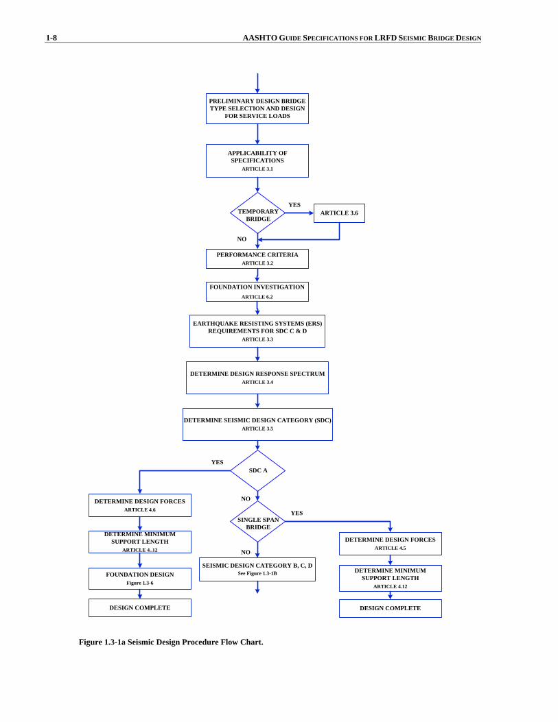
The flow chart in Figure 1a guides the designer on the
applicability of the specifications and the breadth of thedesign procedure dealing with a single span bridge versusa multi-span bridge and a bridge in Seismic DesignCategory A versus a bridge in Seismic Design Category B, C, or D.
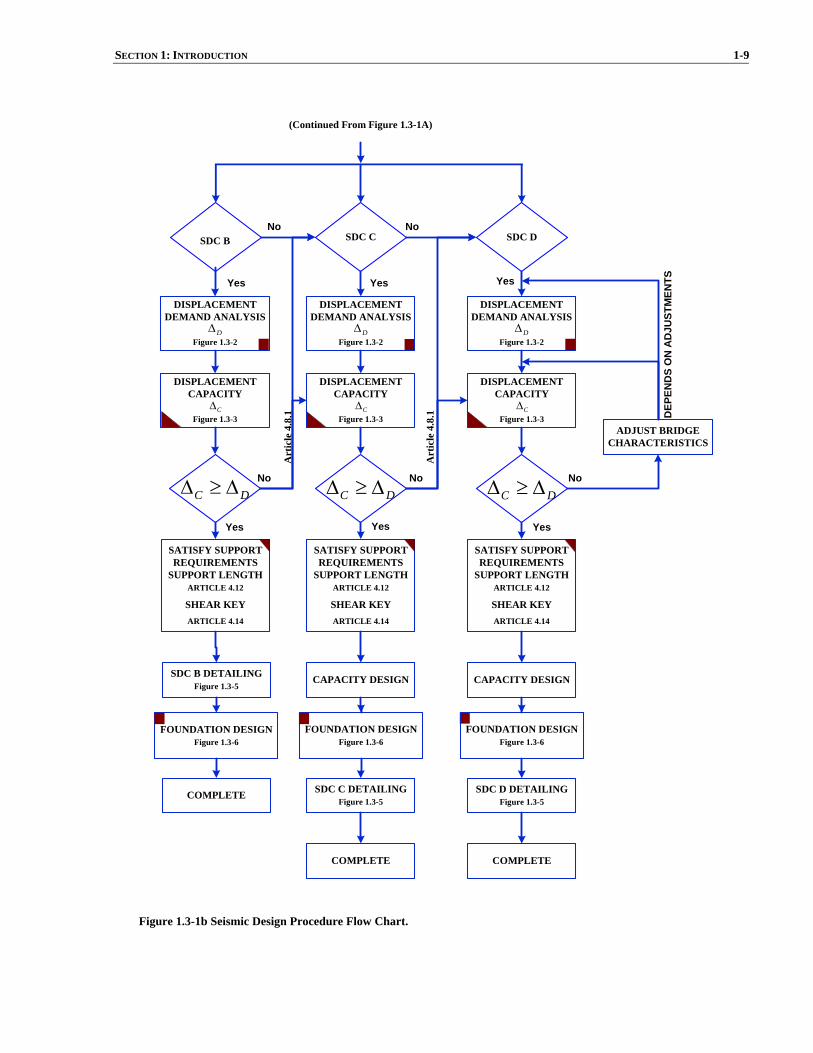
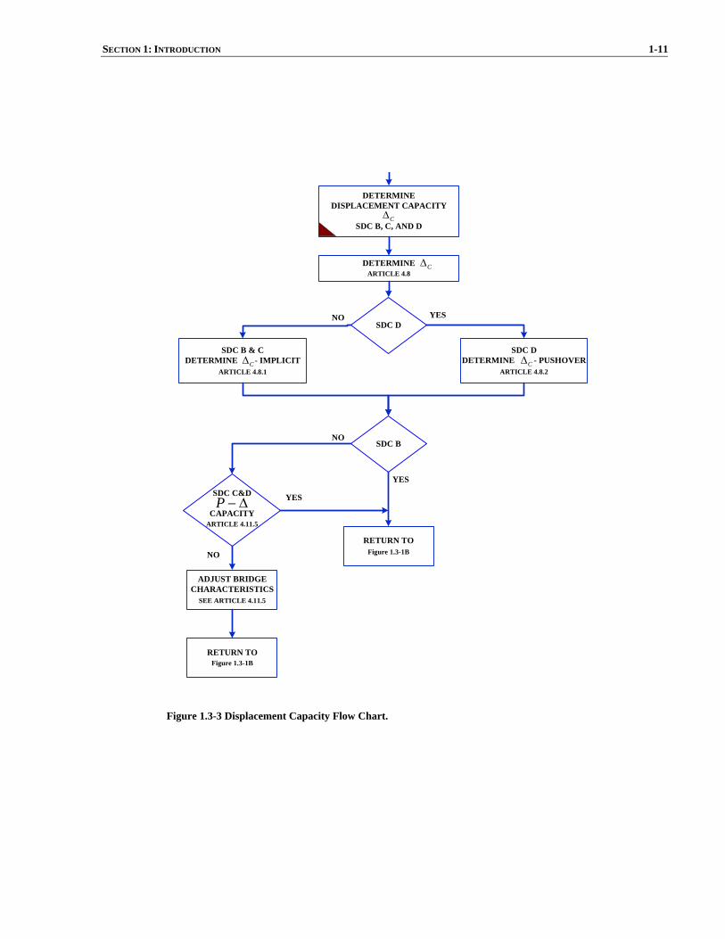
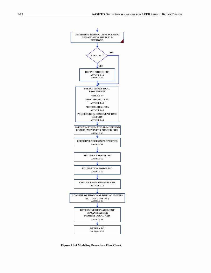
Figure 1b shows the core flow chart of procedures outlined for bridges in SDC B, C, and D. Figure 2 outlines the demand analysis. Figure 3 directs the designer todetermine displacement capacity. Figure 4 shows the modeling procedure. Figures 5a & 5b establish memberdetailing requirements based on the type of the structurechosen for seismic resistance. Figure 6 shows the foundation design.
1-8 AASHTO GUIDE SPECIFICATIONS FOR LRFD SEISMIC BRIDGE DESIGN
PRELIMINARY DESIGN BRIDGETYPE SELECTION AND DESIGN
FOR SERVICE LOADS
APPLICABILITY OFSPECIFICATIONS
ARTICLE 3.1
TEMPORARYBRIDGE
ARTICLE 3.6YES
PERFORMANCE CRITERIAARTICLE 3.2
EARTHQUAKE RESISTING SYSTEMS (ERS)REQUIREMENTS FOR SDC C & D
ARTICLE 3.3
DETERMINE DESIGN RESPONSE SPECTRUMARTICLE 3.4
DETERMINE SEISMIC DESIGN CATEGORY (SDC)ARTICLE 3.5
NO
SDC AYES
NODETERMINE DESIGN FORCESARTICLE 4.6
DETERMINE MINIMUMSUPPORT LENGTH
ARTICLE 4..12
FOUNDATION DESIGNFigure 1.3-6
DESIGN COMPLETE
SINGLE SPANBRIDGE
SEISMIC DESIGN CATEGORY B, C, DSee Figure 1.3-1B
NO
YES
DETERMINE DESIGN FORCESARTICLE 4.5
DETERMINE MINIMUMSUPPORT LENGTH
ARTICLE 4.12
DESIGN COMPLETE
FOUNDATION INVESTIGATIONARTICLE 6.2
Figure 1.3-1a Seismic Design Procedure Flow Chart.
SECTION 1: INTRODUCTION 1-9
SDC B
DISPLACEMENTDEMAND ANALYSIS
Figure 1.3-2
C DΔ ≥ Δ
SDC B DETAILINGFigure 1.3-5
COMPLETE
SDC C
SDC C DETAILINGFigure 1.3-5
COMPLETE
CAPACITY DESIGN
SDC D
SDC D DETAILINGFigure 1.3-5
COMPLETE
CAPACITY DESIGN
Yes Yes Yes
Yes Yes Yes
NoNo No
No No
ADJUST BRIDGECHARACTERISTICS
DEP
END
S O
N A
DJU
STM
ENTS
(Continued From Figure 1.3-1A)
DΔ
DISPLACEMENTDEMAND ANALYSIS
Figure 1.3-2DΔ
DISPLACEMENTDEMAND ANALYSIS
Figure 1.3-2DΔ
DISPLACEMENTCAPACITY
Figure 1.3-3CΔ
DISPLACEMENTCAPACITY
Figure 1.3-3CΔ
DISPLACEMENTCAPACITY
Figure 1.3-3CΔ
C DΔ ≥ Δ C DΔ ≥ Δ
SATISFY SUPPORTREQUIREMENTS
SUPPORT LENGTHARTICLE 4.12
SHEAR KEYARTICLE 4.14
SATISFY SUPPORTREQUIREMENTS
SUPPORT LENGTHARTICLE 4.12
SHEAR KEYARTICLE 4.14
SATISFY SUPPORTREQUIREMENTS
SUPPORT LENGTHARTICLE 4.12
SHEAR KEYARTICLE 4.14
FOUNDATION DESIGNFigure 1.3-6
FOUNDATION DESIGNFigure 1.3-6
FOUNDATION DESIGNFigure 1.3-6
Art
icle
4.8
.1
Art
icle
4.8
.1
Figure 1.3-1b Seismic Design Procedure Flow Chart.

1-10 AASHTO GUIDE SPECIFICATIONS FOR LRFD SEISMIC BRIDGE DESIGN
DISPLACEMENTDEMAND ANALYSIS
SDC B, C, D
SEISMIC DESIGN PROPORTIONINGRECOMMENDATIONS
ARTICLE 4.1
SDC D
CONSIDER VERTICALGROUND MOTION EFFECTS
ARTICLE 4.7.2
YES
SELECT HORIZONTAL AXESFOR GROUND MOTIONS
ARTICLE 4.3.1
DAMPING CONSIDERATIONARTICLE 4.3.2
SHORT PERIOD STRUCTURESCONSIDERATION
ARTICLE 4.3.3
ANALYTICAL MODELING AND PROCEDURES(See Figure1.3-4)
RETURN TOFigure 1.3-1B
NO
DETERMINE ANALYSIS PROCEDUREARTICLE 4.2
DΔ
Figure 1.3-2 Demand Analysis Flow Chart.
SECTION 1: INTRODUCTION 1-11
SDC DDETERMINE - PUSHOVER
ARTICLE 4.8.2
NO
YES
CΔ
CΔ
YES
SDC DNO
DETERMINEARTICLE 4.8
SDC B & CDETERMINE - IMPLICIT
ARTICLE 4.8.1CΔ
SDC B
SDC C&D
CAPACITYARTICLE 4.11.5
Δ−P YES
ADJUST BRIDGECHARACTERISTICS
SEE ARTICLE 4.11.5
NO
DETERMINEDISPLACEMENT CAPACITY
SDC B, C, AND DCΔ
RETURN TOFigure 1.3-1B
RETURN TOFigure 1.3-1B
Figure 1.3-3 Displacement Capacity Flow Chart.
1-12 AASHTO GUIDE SPECIFICATIONS FOR LRFD SEISMIC BRIDGE DESIGN
COMBINE ORTHOGONAL DISPLACEMENTS(i.e., LOADS CASES 1 & 2)
ARTICLE 4.4
DETERMINE SEISMIC DISPLACEMENTDEMANDS FOR SDC B, C, D
SECTION 5
SELECT ANALYTICALPROCEDURES
ARTICLE 5.4
PROCEDURE 1: ESAARTICLE 5.4.2
PROCEDURE 2: EDAARTICLE 5.4.3
PROCEDURE 3: NONLINEAR TIMEHISTORY
ARTICLE 5.4.4
DEFINE BRIDGE ERSARTICLE 5.1.1ARTICLE 3.3
NO
YES
EFFECTIVE SECTION PROPERTIESARTICLE 5.6
SATISFY MATHEMATICAL MODELINGREQUIREMENTS FOR PROCEDURE 2
ARTICLE 5.5
ABUTMENT MODELINGARTICLE 5.2
FOUNDATION MODELINGARTICLE 5.3
SDC C or D
CONDUCT DEMAND ANALYSISARTICLE 5.1.2
RETURN TOSee Figure 1.3-2
DETERMINE DISPLACEMENTDEMANDS ALONG
MEMBER LOCAL AXISARTICLE 4.8
Figure 1.3-4 Modeling Procedure Flow Chart.
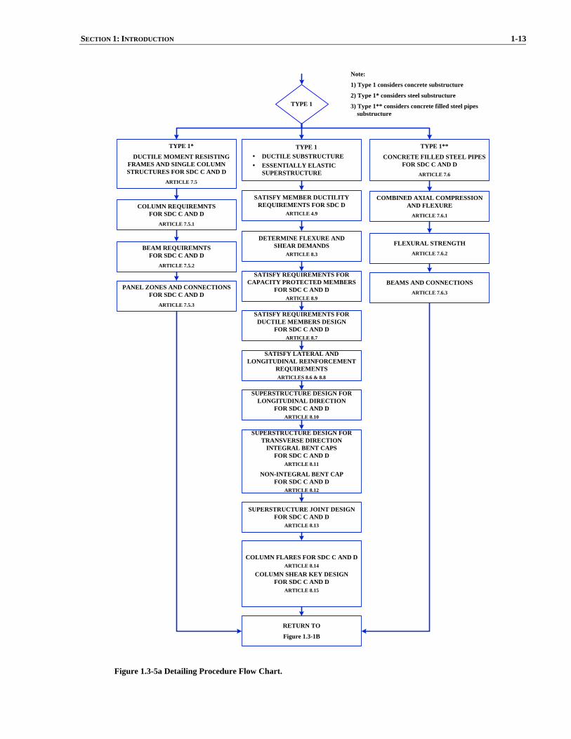
SECTION 1: INTRODUCTION 1-13
TYPE 1DUCTILE SUBSTRUCTUREESSENTIALLY ELASTICSUPERSTRUCTURE
TYPE 1
SATISFY MEMBER DUCTILITYREQUIREMENTS FOR SDC D
ARTICLE 4.9
DETERMINE FLEXURE ANDSHEAR DEMANDS
ARTICLE 8.3
SATISFY REQUIREMENTS FORCAPACITY PROTECTED MEMBERS
FOR SDC C AND DARTICLE 8.9
SATISFY REQUIREMENTS FORDUCTILE MEMBERS DESIGN
FOR SDC C AND DARTICLE 8.7
SATISFY LATERAL ANDLONGITUDINAL REINFORCEMENT
REQUIREMENTSARTICLES 8.6 & 8.8
SUPERSTRUCTURE DESIGN FORLONGITUDINAL DIRECTION
FOR SDC C AND DARTICLE 8.10
SUPERSTRUCTURE DESIGN FORTRANSVERSE DIRECTION
INTEGRAL BENT CAPSFOR SDC C AND D
ARTICLE 8.11
NON-INTEGRAL BENT CAPFOR SDC C AND D
ARTICLE 8.12
SUPERSTRUCTURE JOINT DESIGNFOR SDC C AND D
ARTICLE 8.13
COLUMN FLARES FOR SDC C AND DARTICLE 8.14
COLUMN SHEAR KEY DESIGNFOR SDC C AND D
ARTICLE 8.15
RETURN TO
Figure 1.3-1B
TYPE 1*
DUCTILE MOMENT RESISTINGFRAMES AND SINGLE COLUMNSTRUCTURES FOR SDC C AND D
ARTICLE 7.5
COLUMN REQUIREMNTSFOR SDC C AND D
ARTICLE 7.5.1
BEAM REQUIREMNTSFOR SDC C AND D
ARTICLE 7.5.2
PANEL ZONES AND CONNECTIONSFOR SDC C AND D
ARTICLE 7.5.3
TYPE 1**
CONCRETE FILLED STEEL PIPESFOR SDC C AND D
ARTICLE 7.6
COMBINED AXIAL COMPRESSIONAND FLEXURE
ARTICLE 7.6.1
FLEXURAL STRENGTHARTICLE 7.6.2
BEAMS AND CONNECTIONSARTICLE 7.6.3
Note:
1) Type 1 considers concrete substructure
2) Type 1* considers steel substructure
3) Type 1** considers concrete filled steel pipes substructure
Figure 1.3-5a Detailing Procedure Flow Chart.
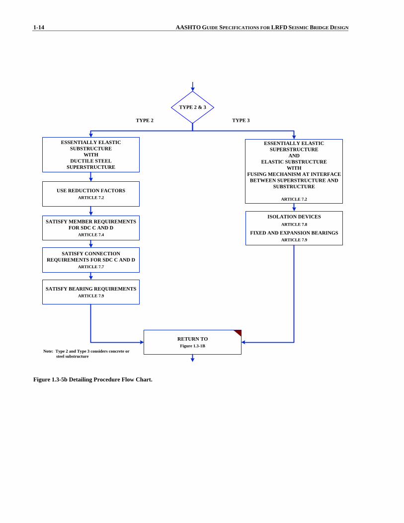
1-14 AASHTO GUIDE SPECIFICATIONS FOR LRFD SEISMIC BRIDGE DESIGN
TYPE 2 & 3
ISOLATION DEVICESARTICLE 7.8
FIXED AND EXPANSION BEARINGSARTICLE 7.9
RETURN TOFigure 1.3-1B
USE REDUCTION FACTORSARTICLE 7.2
SATISFY MEMBER REQUIREMENTSFOR SDC C AND D
ARTICLE 7.4
SATISFY CONNECTIONREQUIREMENTS FOR SDC C AND D
ARTICLE 7.7
SATISFY BEARING REQUIREMENTSARTICLE 7.9
Note: Type 2 and Type 3 considers concrete or steel substructure
TYPE 2 TYPE 3
ESSENTIALLY ELASTICSUBSTRUCTURE
WITHDUCTILE STEEL
SUPERSTRUCTURE
ESSENTIALLY ELASTICSUPERSTRUCTURE
ANDELASTIC SUBSTRUCTURE
WITHFUSING MECHANISM AT INTERFACE
BETWEEN SUPERSTRUCTURE ANDSUBSTRUCTURE
ARTICLE 7.2
Figure 1.3-5b Detailing Procedure Flow Chart.
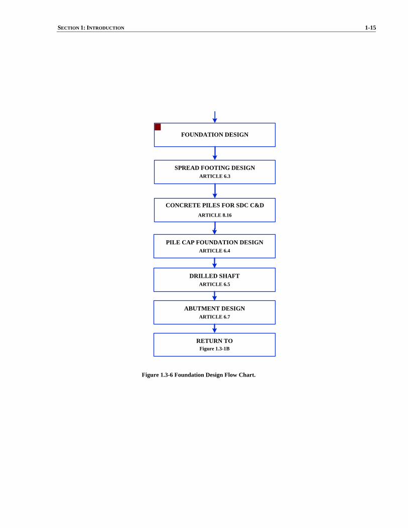
SECTION 1: INTRODUCTION 1-15
CONCRETE PILES FOR SDC C&DARTICLE 8.16
ABUTMENT DESIGNARTICLE 6.7
RETURN TOFigure 1.3-1B
SPREAD FOOTING DESIGNARTICLE 6.3
PILE CAP FOUNDATION DESIGNARTICLE 6.4
DRILLED SHAFTARTICLE 6.5
FOUNDATION DESIGN
Figure 1.3-6 Foundation Design Flow Chart.


SECTION 2: DEFINITIONS AND NOTATION
TABLE OF CONTENTS
2-i
2.1 DEFINITIONS.......................................................................................................................................................... 1 2.2 NOTATION.............................................................................................................................................................. 3


SECTION 2
DEFINITIONS AND NOTATION
2-1
2.1 DEFINITIONS Capacity Design – A method of component design that allows the designer to prevent damage in certain components by making them strong enough to resist loads that are generated when adjacent components reach their overstrength capacity. Capacity Protected Element – Part of the structure that is either connected to a critical element or within its load path and that is prevented from yielding by virtue of having the critical member limit the maximum force that can be transmitted to the capacity protected element. Collateral Seismic Hazard – Seismic hazards other than direct ground shaking such as liquefaction, fault rupture, etc. Complete Quadratic Combination (CQC) – A statistical rule for combining modal responses from an earthquake load applied in a single direction to obtain the maximum response due to this earthquake load. Critical or Ductile Elements – Parts of the structure that are expected to absorb energy, undergo significant inelastic deformations while maintaining their strength and stability. Damage Level – A measure of seismic performance based on the amount of damage expected after one of the design earthquakes. Displacement Capacity Verification – A design and analysis procedure that requires the designer to verify that his or her structure has sufficient displacement capacity. It generally involves a non-linear static (i.e. “pushover”) analysis. Ductile Substructure Elements – See Critical or Ductile Elements Earthquake Resisting Element (ERE) – The individual components, such as columns, connections, bearings, joints, foundation, and abutments, that together constitute the Earthquake Resisting System (ERS). Earthquake Resisting System (ERS) – A system that provides a reliable and uninterrupted load path for transmitting seismically induced forces into the ground and sufficient means of energy dissipation and/or restraint to reliably control seismically induced displacements. Life Safety Performance Level – The minimum acceptable level of seismic performance allowed by this specification. It is intended to protect human life during and following a rare earthquake. Liquefaction – Seismically induced loss of shear strength in loose, cohesionless soil that results from a build up of pore water pressure as the soil tries to consolidate when exposed to seismic vibrations. Liquefaction-Induced Lateral Flow – Lateral displacement of relatively flat slopes that occurs under the combination of gravity load and excess pore water pressure (without inertial loading from earthquake). Lateral flow often occurs after the cessation of earthquake loading. Liquefaction-Induced Lateral Spreading – Incremental displacement of a slope that occurs from the combined effects of pore water pressure buildup, inertial loads from the earthquake, and gravity loads. Maximum Considered Earthquake (MCE) – The upper level, or rare, design earthquake having ground motions with a 3% chance of being exceeded in 75 years. In areas near highly-active faults, the MCE ground motions are deterministically bounded to ground motions that are lower than those having a 3% chance of being exceeded in 75 years. Minimum Support Width – The minimum prescribed width of a bearing seat that is required to be provided in a new bridge designed according to these specifications.

2-2 AASHTO GUIDE SPECIFICATION FOR LRFD SEISMIC BRIDGE DESIGN Nominal Resistance – Resistance of a member, connection or structure based on the expected yield strength (Fye) or other specified material properties, and the nominal dimensions and details of the final section(s) chosen, calculated with all material resistance factors taken as 1.0. Operational Performance Level – A higher level of seismic performance that may be selected by a bridge owner who wishes to have immediate service and minimal damage following a rare earthquake. Overstrength Capacity – The maximum expected force or moment that can be developed in a yielding structural element assuming overstrength material properties and large strains and associated stresses. Performance Criteria – The levels of performance in terms of post earthquake service and damage that are expected to result from specified earthquake loadings if bridges are designed according to this specification. Plastic Hinge – The region of a structural component, usually a column or a pier in bridge structures, that undergoes flexural yielding and plastic rotation while still retaining sufficient flexural strength. Pushover Analysis – See Displacement Capacity Verification Plastic Hinge Zone – Those regions of structural components that are subject to potential plastification and thus shall be detailed accordingly. Response Modification Factor (R-Factor) – Factors used to modify the element demands from an elastic analysis to account for ductile behavior and obtain design demands. Seismic Design Category (SDC) – one of four Seismic Design Categories (SDC), A through D, based on the one second period design spectral acceleration for the Life Safety Design Earthquake Service Level – A measure of seismic performance based on the expected level of service that the bridge is capable of providing after one of the design earthquakes. Site Class – One of six classifications used to characterize the effect of the soil conditions at a site on ground motion. Tributary Weight – The portion of the weight of the superstructure that would act on a pier participating in the ERS if the superstructure between participating piers consisted of simply supported spans. A portion of the weight of the pier itself may also be included in the tributary weight.

SECTION 2: DEFINITIONS AND NOTATION 2-3 2.2 NOTATION The following symbols and definitions apply to these Guide Specifications: A = cross sectional area of member (in.2) (7.5.2) Ac = area of the concrete core (in.2) (C7.6) (7.6.1) (7.6.2)
botcapA = area of bent cap bottom flexural steel (in.2) (8.13.4.2.3) topcapA = area of bent cap top flexural steel (in.2) (8.13.4.2.3)
Ae = effective area of the cross section for shear resistance (in.2) (8.6.2) (8.6.4) (8.6.9) Aew = cross sectional area of pier wall (in.2) (5.6.2) Ag = gross area of section along the plane resisting tension (in.2); gross area of member cross section (in.2) (7.7.6)
(8.6.2) (8.7.2) (8.8.1) (8.8.2) Agg = gross area of gusset plate (in.2) (7.7.9) Ajh = effective horizontal joint area (in.) (8.13.2)
ftgjhA = effective horizontal area at mid-depth of the footing assuming a 45o spread away from the boundary of the
column in all directions as shown in Figure 6.4.5-1 (in.2) (6.4.5) Ajv = effective vertical joint area (in.) (8.13.2) Al = area of longitudinal reinforcement in member (in.2) (8.8.1) (8.8.2) An = net area of section along the plane resisting tension (in.2) (7.7.6) As = area of the steel pipe (in.2) (C7.6)
barjsA − = area of vertical j-dowels hooked around the longitudinal top deck steel required at moment resisting joints for
integral cap of bent with a skew angle >20º (in.2) (8.13.4.2.4) jh
sA = cross sectional area of horizontal stirrups required at moment resisting joints (in.2) (8.13.4.2.2) jl
sA = cross sectional area of required additional longitudinal cap beam reinforcement (in.2) (8.13.5.1.3) jv
sA = cross sectional area of vertical stirrups required at moment resisting joints (in.2) (8.13.4.2.1) jvi
sA = cross sectional area of vertical stirrup required inside the joint region (in.2) (8.13.5.1.2) jvo
sA = cross sectional area of vertical stirrup required outside the joint region (in.2) (8.13.5.1.1) sfsA = total longitudinal (horizontal) side face reinforcement in the bent cap required at moment resisting joints
(in.2) (8.13.4.2.3) Asp = area of spiral or hoop reinforcement (in.2) (8.6.2) (8.6.3) Ast = total area of column reinforcement anchored in the joint (in.2) (8.13.3) (8.13.4.2.1) (8.13.4.2.2) (8.13.4.2.4)
(8.13.5.1.1) (8.13.5.1.2) (8.13.5.1.3) Atg = gross area of section along the plane resisting tension in block shear failure mode (in.2) (7.7.6) Atn = net area of section along the plane resisting tension in block shear failure mode (in.2) (7.7.6) Av = cross sectional area of shear reinforcement in the direction of loading (in.2) (8.6.2) (8.6.3) (8.6.9) Avg = gross area of section along the plane resisting shear in block shear failure mode (in.2) (7.7.6) Avn = net area of section along the plane resisting shear in block shear failure mode (in.2) (7.7.6) B = width of footing measured normal to the direction of loading (ft.) (6.3.4) (6.3.6) Bc = diameter or width of column or wall measured normal to the direction of loading (in.) (6.3.6) (6.4.5) Bcap = thickness of the bent cap (in.) (8.11) (8.13.2) Beff
= effective width of the superstructure or bent cap for resisting longitudinal seismic moment (in.) (8.10) (8.11) ftg
effB = effective width of footing (in.) (6.4.5) Bo = column diameter or width measured parallel to the direction of displacement under consideration (ft.) (4.8.1) b = width of unstiffened or stiffened element (in.); width of column or wall in direction of bending (in.) (7.4.2)
(8.6.2) (8.6.9) beff = effective width of the footing used to calculate the nominal moment capacity of the footing (ft.) (6.3.6) b/t = width-thickness ratio of unstiffened or stiffened element (7.4.2)
pileiC )( = compression force in “ith” pile (kip) (6.4.2)
cx(i) = distance from neutral axis of pile group to “ith” row of piles measured parallel to the “x” axis (ft.) (6.4.2) cy(i) = distance from neutral axis of pile group to “ith” row of piles measured parallel to the “y” axis (ft.) (6.4.2) D = distance from active fault (miles); diameter of HSS tube (in.); outside diameter of steel pipe (in.); diameter of
column or pile (in.) (3.4.3) (3.4.4) (7.4.2) (7.6.2) (8.16.1) D’ = diameter of spiral or hoop (in.) (8.6.2) (8.6.3)

2-4 AASHTO GUIDE SPECIFICATION FOR LRFD SEISMIC BRIDGE DESIGN D/C = displacement demand to capacity ratio (3.5) D/t = diameter to thickness ratio of a steel pipe (7.4.2) (C7.6.1) D* = diameter of circular shafts or cross section dimension in direction under consideration for oblong shafts (in.)
(4.11.6) Dc = diameter or depth of column in direction of loading (ft. or in.) (6.3.2) (C6.3.6) (8.8.6) (8.10) (8.13.2)
(8.13.4.2.4) (8.13.5) Dcj = column width or diameter parallel to the direction of bending (in.) (6.4.5) Dc,max = larger cross section dimension of the column (in.) (8.8.10) (8.8.13) Dftg = depth of the pile cap or footing (ft. or in.) (6.4.2) (6.4.5) Dg = width of gap between backwall and superstructure (ft.) (5.2.3.3) Ds = depth of superstructure at the bent cap (in.) (8.7.1) (8.10) (8.13.2) d = depth of superstructure or cap beam (in.); overall depth of section (in.); depth of section in direction of
loading (in.) (4.11.2) (8.13.5) (7.4.2) (8.6.3) (8.6.9) dbl = nominal diameter of longitudinal column reinforcing steel bars (in.) (4.11.6) (8.8.4) (8.8.6) di = thickness of “ith” soil layer (ft.) (3.4.2.2) E = modulus of elasticity of steel (ksi) (7.4.2) (7.7.5) Ec = modulus of elasticity of concrete (ksi) (5.6.2) (C7.6) EcIeff = effective flexural stiffness (kip-in2) (5.6.1) (5.6.2) Es = modulus of elasticity of steel (ksi) (C7.6) (8.4.2) Fa = site coefficient for 0.2 second period spectral acceleration (3.4.1) (3.4.2.3) Fu = minimum tensile strength of steel (ksi) (7.7.6) Fv = site coefficient for 1.0 second period spectral acceleration (3.4.1) (3.4.2.3) Fw = factor taken as between 0.01 to 0.05 for soils ranging from dense sand to compacted clays (5.2.3.3) Fy = specified minimum yield strength of steel (ksi); nominal yield stress of steel pipe or steel gusset plate (ksi)
(7.3) (7.4.1) (7.4.2) (7.7.6) (7.6.2) (7.7.5) (7.7.8) (7.7.9) Fye = expected yield stress of structural steel member (ksi) (7.3) (7.5.2)
cf ′ = nominal uniaxial compressive concrete strength (ksi) (6.4.5) (7.6.1) (7.6.2) (8.4.4) (8.6.2) (8.6.4) (8.6.9) (8.7.2) (8.8.4) (8.8.6) (C8.13.2) (8.13.3)
ccf ′ = confined compressive strength of concrete (ksi) (8.4.4)
cef ′ = expected concrete compressive strength (ksi) (8.4.4) (C8.13.2) fh = average normal stress in the horizontal direction within a moment resisting joint (ksi) (8.13.2) fps = stress in prestressing steel corresponding to strain εps (ksi) (8.4.3) fue = expected tensile strength (ksi) (8.4.2) fv = average normal stress in the vertical direction within a moment resisting joint (ksi) (6.4.5) (8.13.2) fy = specified minimum yield stress (ksi) (8.4.2) fye = expected yield strength (ksi) (4.11.6) (8.4.2) (8.8.4) (8.8.6) (8.11) fyh = yield stress of spiral, hoop or tie reinforcement (ksi) (8.6.2) (8.6.3) (8.6.9) (8.8.8) (8.13.3) G = soil dynamic (secant) shear modulus (ksi) (5.3.2) (GA)eff = effective shear stiffness parameter of the pier wall (kip) (5.6.1) (5.6.2) Gc = shear modulus of concrete (ksi) (5.6.2) GcJeff = torsional stiffness (5.6.1) Gf = gap between the isolated flare and the soffit of the bent cap (in.) (4.11.6) Gmax = soil low-strain (initial) shear modulus (5.3.2) g = acceleration due to gravity (ft./sec.2 or in./sec.2) (C5.4.2) H = thickness of soil layer (ft.); column height used to calculate minimum support length (in.) (3.4.2.1) (4.12.1) Hf = depth of footing (ft.) (6.3.2) (6.3.4) (6.3.6) Hh = the height from the top of the footing to the top of the column or the equivalent column height for a pile
extension column (ft.) (8.7.1) Ho
= clear height of column (ft.) (4.8.1) Hw = height of backwall or diaphragm (ft.) (5.2.3.3) H ′ = length of pile shaft/column from point of maximum moment to point of contraflexure above ground (in.)
(4.11.6) h = web depth (in.); distance from c.g. of tensile force to c.g. of compressive force on the section (in.) (7.4.2)
(8.13.2) h/tw = web depth-thickness ratio (7.4.2) Ic = moment of inertia of the concrete core (in.4) (C7.6)

SECTION 2: DEFINITIONS AND NOTATION 2-5 Ieff = effective moment of inertia of the section based upon cracked concrete and first yield of the reinforcing steel
(in.4); effective moment of inertia of the section based upon cracked concrete and first yield of the reinforcing steel or effective moment of inertia taken about the weak axis of the reinforced concrete cross section (in.4) (5.6.1) (5.6.2) (5.6.3) (5.6.4)
Ig = gross moment of inertia taken about the weak axis of the reinforced concrete cross section (in.4) (5.6.2) (5.6.3) (5.6.4)
Ipg(x) = effective moment of inertia of pile group about the “x” axis (pile-ft.2) (6.4.2) Ipg(y) = effective moment of inertia of pile group about the “y” axis (pile-ft.2) (6.4.2) Is = moment of inertia of a single longitudinal stiffener about an axis parallel to the flange and taken at the base
of the stiffener (in.4); moment of inertia of the steel pipe (in.4) (7.4.2) (C7.6) Jeff = effective torsional (polar) moment of inertia of reinforced concrete section (in.4) (5.6.1) (5.6.5) Jg = gross torsional (polar) moment of inertia of reinforced concrete section (in.4) (5.6.5) K = effective lateral bridge stiffness (kip/ft. or kip/in.); effective length factor of a member (C5.4.2) (7.4.1) KDED = stiffness of the ductile end diaphragm (kip/in.) (7.4.6) Keff = abutment equivalent linear secant stiffness (kip/ft.) (5.2.3.3) Ki = initial abutment backwall stiffness (kip/ft.) (5.2.3.3) KL/r = slenderness ratio (7.4.1) KSUB = stiffness of the substructure (kip/in.) (7.4.6) k = total number of cohesive soil layers in the upper 100 ft. of the site profile below the bridge foundation; plate
buckling coefficient for uniform normal stress (3.4.2.2) (7.4.2) eik = smaller effective bent or column stiffness (kip/in.) (4.1.1) ejk = larger effective bent or column stiffness (kip/in.) (4.1.1)
L = length of column from point of maximum moment to the point of moment contra-flexure (in.); length of the bridge deck to the adjacent expansion joint, or to the end of the bridge deck; for hinges within a span, L shall be the sum of the distances to either side of the hinge; for single-span bridges, L equals the length of the bridge deck (ft.); total length of bridge (ft. or in.); length of footing measured in the direction of loading (ft.); unsupported length of a member (in.) (4.11.6) (8.8.6) (4.12.1) (C5.4.2) (6.3.2) (6.3.4) (C6.3.6) (7.4.1)
Lc = column clear height used to determine shear demand (in.) (4.11.2) Lftg = cantilever overhang length measured from the face of wall or column to the outside edge of the pile cap or
footing (ft.) (6.4.2) Lg = unsupported edge length of the gusset plate (in.) (7.7.5) Lp = equivalent analytical plastic hinge length (in) (4.11.6) (4.11.7) Lpr = plastic hinge region which defines the portion of the column, pier or shaft that requires enhanced lateral
confinement (in.) (4.11.7) Lu = unsupported length (in.) (C7.4.1) lac = length of column reinforcement embedded into the bent cap or footing (in.) (8.8.4) (8.13.2) (8.13.3) Mg = moment acting on the gusset plate (kip-in.) (7.7.10) Mn = nominal moment capacity (kip-in. or kip-ft.) (4.11.2) (4.11.5) (6.3.6) Mne = nominal moment capacity of a reinforced concrete member based on expected materials properties and a
concrete strain εc = 0.003 (kip-ft.) (8.5) (8.7.1) (8.9) Mng = nominal moment strength of a gusset plate (kip-in.) (7.7.8) Mns = nominal flexural moment strength of a member (kip-in.) (7.4.1) Mnx = probable flexural resistance of column (kip-ft.) (7.5.2) Mp = idealized plastic moment capacity of reinforced concrete member based upon expected material properties
(kip-in. or kip-ft.) (4.11.2) (4.11.5) (8.5) col
xpM )( = the component of the column overstrength plastic hinging moment capacity about the “x” axis (kip-ft.) (6.4.2)
colypM )( = the component of the column overstrength plastic hinging moment capacity about the “y” axis (kip-ft.)
(6.4.2) Mpo = overstrength plastic moment capacity of the column (kip-in. or kip-ft.) (4.11.2) (6.3.4) (8.5) (8.9) (8.10)
(8.13.1) (8.13.2) (8.15) Mpg = nominal plastic moment strength of a gusset plate (kip-in.) (7.7.8) Mpx = plastic moment capacity of the member based upon expected material properties (kip-ft.) (7.5.2) Mrc = factored nominal moment capacity of member (kip-ft.) (7.6.1) Mrg = factored nominal yield moment capacity of the gusset plate (kip-in.) (7.7.10) Mrpg = factored nominal plastic moment capacity of the gusset plate (kip-in.) (7.7.10)

2-6 AASHTO GUIDE SPECIFICATION FOR LRFD SEISMIC BRIDGE DESIGN Mu = factored ultimate moment demand (kip-ft. or kip-in.); factored moment demand acting on the member
including the elastic seismic demand divided by the appropriate force reduction factor, R (kip-ft.) (6.3.6) (7.4.1) (7.6.1)
My = moment capacity of section at first yield of the reinforcing steel (kip-in.) (5.6.2) m = total number of cohesionless soil layers in the upper 100 ft. of the site profile below the bridge foundation
(3.4.2.2) mi = tributary mass of column or bent i (kip) (4.1.1) mj = tributary mass of column or bent j (kip) (4.1.1) N = minimum support length measured normal to the centerline of bearing (in.) (4.12) (4.12.1) (4.12.2) N = average standard penetration resistance for the top 100 ft. (blows/ft.) (3.4.2)
chN = average standard penetration resistance of cohesionless soil layers for the top 100 ft. (blows/ft.) (3.4.2) Ni = standard penetration resistance as measured directly in the filed, uncorrected blow count, of “ith” soil layer
not to exceed 100 (blows/ft.) (3.4.2.2) Np = total number of piles in the pile group (pile) (6.4.2) n = total number of distinctive soil layers in the upper 100 ft. of the site profile below the bridge foundation;
number of equally spaced longitudinal compression flange stiffeners; modular ratio; number of individual interlocking spiral or hoop core sections (3.4.2.2) (7.4.2) (C7.6) (8.6.3)
nx = number of piles in a single row parallel to the “x” axis (pile) (6.4.2) ny = number of piles in a single row parallel to the “y” axis (pile) (6.4.2) Pb = beam axial force at the center of the joint including prestressing (kip) (8.13.2) Pbs = tensile strength of a gusset plate based on block-shear (kip) (7.7.6) Pc = column axial force including the effects of overturning (kip) (8.13.2) Pcol = column axial force including the effects of overturning (kip) (6.4.5) Pdl = unfactored dead load acting on column (kip) (4.11.5) Pg = axial force acting on the gusset plate (kip) (7.7.10) PI = plasticity index of soil (3.4.2.1) Pn = nominal axial strength of a member (kip) (7.4.1) Png = nominal compression strength of the gusset plates (kip) (7.7.7) Pp = abutment passive lateral earth capacity (kip) (5.2.3.3) Pr = factored nominal axial capacity of member (kip) (7.6.1) Prg = factored nominal yield axial capacity of the gusset plate (kip) (7.7.10) Pro = factored nominal axial capacity of member (kip) (7.6.1) Ptrib = greater of the dead load per column or force associated with the tributary seismic mass collected at the bent
(kip) (8.7.1) Pu = axial force in column including the axial force associated with overstrength plastic hinging (kip); factored
axial compressive load acting on the member (kip); factored axial load acting on the member (kip); ultimate compressive force acting on section (kip); ultimate compressive force acting on the section including seismic induced vertical demands (kip) (6.3.4) (C6.3.6) (7.4.1) (7.4.2) (7.5.2) (8.6.2) (8.7.2)
Py = nominal axial yield strength of a member (kip) (7.4.2) pc = principal compressive stress (ksi) (6.4.5) (8.13.2) pe = equivalent uniform static lateral seismic load per unit length of bridge applied to represent the primary mode
of vibration (kip/ft.) (C5.4.2) pp = passive lateral earth pressure behind backwall (ksf) (5.2.3.3) po = uniform lateral load applied over the length of the structure (kip/ft. or kip/in.) (C5.4.2) pt = principal tensile stress (ksi) (6.4.5) (8.13.2) qn = nominal bearing capacity of supporting soil or rock (ksf) (6.3.4) R = maximum expected displacement ductility of the structure; response modification factor (4.3.3) (7.2) (7.2.2)
(7.4.6) RD = damping reduction factor to account for increased damping (4.3.2) Rd = magnification factor to account for short period structure (4.3.3) Rn = nominal resistance against sliding failure (6.3.5) r = radius of gyration (in.) (7.4.1) ry = radius of gyration about minor axis (in.) (7.4.1) S = angle of skew of support measured from a line normal to span (°) (4.12.1) (4.12.2) Sa = design response spectral acceleration coefficient (3.4.1) (C5.4.2) S1 = 1.0 second period spectral acceleration coefficient on Class B rock (3.4.1) SD1 = design earthquake response spectral acceleration coefficient at 1.0 second period (3.4.1) (3.5) SDS = design earthquake response spectral acceleration coefficient at 0.2 second period (3.4.1)

SECTION 2: DEFINITIONS AND NOTATION 2-7 Ss = 0.2 second period spectral acceleration coefficient on Class B rock (3.4.1) Sg = elastic section modulus of gusset plate about the strong axis (in.3) (7.7.8) s = spacing of spiral, hoop or tie reinforcement (in.) (8.6.2) (8.6.3) (8.6.9)
us = average undrained shear strength in the top 100 ft. (psf) (3.4.2) sui = undrained shear strength of “ith” soil layer not to exceed 5 (ksf) (3.4.2.2) T = period of vibration (sec.); fundamental period of the structure (sec.) (3.4.1) (4.3.3) Tc = column tensile force associated with the column overstrength plastic hinging moment, Mpo (kip) (6.4.5)
(8.13.2) TF = bridge fundamental period (sec.) (3.4.3) Ti = natural period of the less flexible frame (sec.) (4.1.2)
pileiT )( = tension force in “ith” pile (kip) (6.4.2)
Tj = natural period of the more flexible frame (sec.) (4.1.2) Tjv = net tension force in moment resisting footing joints (kip) (6.4.5) Tm = period of the mth mode of vibration (sec.) (C5.4.2) To = period at beginning of constant design spectral acceleration plateau (sec.) (3.4.1) Ts = period at the end of constant design spectral acceleration plateau (sec.) (3.4.1) (4.3.3) T* = characteristic ground motion period (sec.) (4.3.3) t = thickness of unstiffened or stiffened element (in.); pipe wall thickness (in.); thickness of gusset plate (in.);
thickness of the top or bottom slab (in.) (7.4.2) (7.6.2) (7.7.5) (8.11) tw = thickness of web plate (in.) (7.4.2) Vc = nominal shear resistance of the concrete (kip) (8.6.1) (8.6.2) Vg = shear force acting on the gusset plate (kip) (7.7.10) Vn = nominal interface shear capacity of shear key as defined in Article 5.8.4 of the AASHTO LRFD Bridge
Design Specifications using the expected material properties and interface surface conditions (kip); nominal shear capacity (kip) (4.14) (6.3.7) (8.6.1) (8.6.9)
Vng = nominal shear strength of a gusset plate (kip) (7.7.9) Vok = overstrength capacity of shear key (4.14) (8.12) Vpo = overstrength shear associated with the overstrength moment Mpo (kip) (4.11.2) (6.3.4) (6.3.5) (8.6.1) Vrg = factored nominal yield shear capacity of the gusset plate (kip) (7.7.10) Vs = nominal shear resistance of the steel (kip) (8.6.1) (8.6.3) (8.6.4) Vu = factored ultimate shear demand in footing at the face of the column or wall (kip); shear demand of a column
or wall (kip) (6.3.7) (8.6.1) (8.6.9) vc = concrete shear stress capacity (ksi) (8.6.2) vjv = nominal vertical shear stress in a moment resisting joint (ksi) (6.4.5) (8.13.2)
sv = average shear wave velocity in the top 100 ft. (ft./sec.) (3.4.2) vsi = shear wave velocity of “ith” soil layer (ft./sec.) (3.4.2.2) Vs,max = maximum lateral displacement due to uniform loading po (ft. or in.) (C5.4.2) W = total weight of bridge (kip) (C5.4.2) Ww = width of backwall (ft.) (5.2.3.3) w = moisture content (%) (3.4.2.1) w(x) = nominal unfactored dead load of the bridge superstructure and tributary substructure (kip/ft. or kip/in.)
(C5.4.2) Z = plastic section modulus of steel pipe (in.3) (7.6.2) Zg = plastic section modulus of gusset plate about the strong axis (in.3) (7.7.8) β = central angle formed between neutral axis chord line and the center point of the pipe found by the recursive
equation (rad.) (7.6.2) γEQ = load factor for live load (C4.6) ∆b = displacement demand due to flexibility of essentially elastic components such as bent caps (in.) (4.3)
LCΔ = displacement capacity taken along the local principal axis corresponding to L
DΔ of the ductile member as determined in accordance with Article 4.8.1 for SDC B and C and in accordance with Article 4.8.2 for SDC D (in.) (C3.3) (4.8) (4.8.1)
ΔD = global seismic displacement demand (in.) (4.3.1) (4.11.5) LDΔ = displacement demand taken along the local principal axis of the ductile member as determined in accordance
with Article 4.4 (in.) (C3.3) (4.8) ∆eq = seismic displacement demand of the long period frame on one side of the expansion joint (in.) (4.12.2) ΔF = pile cap displacement (in.) (4.11.5)

2-8 AASHTO GUIDE SPECIFICATION FOR LRFD SEISMIC BRIDGE DESIGN ∆f = displacement demand attributed to foundation flexibility; pile cap displacements (in.) (4.3) Δpd = displacement demand attributed to inelastic response of ductile members; plastic displacement demand (in.)
(4.3) (4.9) Δr = relative lateral offset between the point of contra-flexure and the furthest end of the plastic hinge (in.)
(4.11.5) ΔS = pile shaft displacement at the point of maximum moment developed in-ground (in.) (4.11.5) ∆y = idealized yield displacement; displacement demand attributed to elastic response of ductile members (in.)
(C3.3) (4.3) Δyi = idealized yield displacement (in.) (C3.3) (4.9) εcc = compressive strain at maximum compressive stress of confined concrete (8.4.4) εco = unconfined concrete compressive strain at the maximum compressive stress (8.4.4) εcu = ultimate compressive strain for confined concrete (8.4.4) εsp = ultimate unconfined compression (spalling) strain (8.4.4) εps = strain in prestessing steel (in./in.) (8.4.3) εps,EE = essentially elastic prestress steel strain (8.4.3) εps,u = ultimate prestress steel strain (8.4.3)
Rups,ε = reduced ultimate prestress steel strain (8.4.3)
εsh = tensile strain at the onset of strain hardening (8.4.2) εsu = ultimate tensile strain (8.4.2)
Rsuε = reduced ultimate tensile strain (8.4.2)
εye = expected yield strain (8.4.2) μ = displacement ductility capacity of the end diaphragm (7.4.6) μC = ductility capacity (4.7.1) μD = maximum local member displacement ductility demand (4.3.3) (4.7.1) (4.9) (8.6.2) λb = slenderness parameter for flexural moment dominant members (7.4.1) λbp = limiting slenderness parameter for flexural moment dominant members (7.4.1) λc = slenderness parameter for axial compressive load dominant members (7.4.1) λcp = limiting slenderness parameter for axial compressive load dominant members (7.4.1) λmo = overstrength factor (4.11.2) (7.3) (8.5.1) λp = limiting width-thickness ratio for ductile components (7.4.2) λr = limiting width-thickness ratio for essentially elastic components (7.4.2) ρh = horizontal reinforcement ratio in pier wall (8.6.9) (8.6.10) ρs = volumetric ratio of spiral reinforcement for a circular column (8.6.2) (8.6.5) (8.8.7) (8.13.3) ρv = vertical reinforcement ratio in pier wall (8.6.10) ρw = reinforcement ratio in the direction of bending (8.6.2) (8.6.5) (8.8.7) φ = resistance factor (3.7) (6.3.4) (6.3.5) (6.3.6) (7.3) φb = 0.9 resistance factor for flexure (7.4.2) φbs = 0.80 resistance factor for block shear failure mechanisms (7.7.6) φc = 0.75 resistance factor for concrete in compression (7.6.1) φf = 1.0 resistance factor for structural steel in flexure (7.6.2) φs = 0.85 resistance factor for shear in reinforce concrete (6.3.7) (8.6.1) (8.6.9) φu = 0.80 resistance factor for fracture on net section; ultimate curvature capacity (7.7.6) (8.5) φy = curvature of section at first yield of the reinforcing steel including the effects of the unfactored axial dead
load(1/in.); 0.95 resistance factor for yield on gross section (5.6.2) (8.5) (7.7.6) φyi = idealized yield curvature (8.5) Λ = factor for column end restraint condition (4.8.1) (8.7.1) ξ = damping ratio (maximum of 0.1) (4.3.2)
∑=
n
iid
1 = thickness of upper soil layers = 100 ft. (3.4.2.2)
∑ pileiT )( = summation of the hold down force in the tension piles (kip) (6.4.5)
∑ P = total unfactored axial load due to dead load, earthquake load, footing weight, soil overburden and all other vertical demands acting on the pile group (kip) (6.4.2)

SECTION 3: GENERAL REQUIREMENTS
TABLE OF CONTENTS
3-i
3.1 APPLICABILITY OF SPECIFICATIONS ...........................................................................................................3-1 3.2 PERFORMANCE CRITERIA...............................................................................................................................3-1 3.3 EARTHQUAKE RESISTING SYSTEMS (ERS) REQUIREMENTS FOR SDC C & D .....................................3-2 3.4 SEISMIC GROUND SHAKING HAZARD........................................................................................................3-11
3.4.1 Design Spectra Based on General Procedure.............................................................................................3-12 3.4.2 Site Effects on Ground Motions.................................................................................................................3-42
3.4.2.1 Site Class Definitions.......................................................................................................................3-43 3.4.2.2 Definitions of Site Class Parameters................................................................................................3-44 3.4.2.3 Site Coefficients...............................................................................................................................3-45
3.4.3 Response Spectra Based on Site-Specific Procedures ...............................................................................3-46 3.4.4 Acceleration Time-Histories ......................................................................................................................3-47
3.5 SELECTION OF SEISMIC DESIGN CATEGORY (SDC)................................................................................3-50 3.6 TEMPORARY AND STAGED CONSTRUCTION ...........................................................................................3-52 3.7 LOAD AND RESISTANCE FACTORS .............................................................................................................3-52

SECTION 3
GENERAL REQUIREMENTS
3-1
Chapter 3 3.1 APPLICABILITY OF SPECIFICATIONS
These Specifications are for the design and
construction of new bridges to resist the effects ofearthquake motions. The provisions apply to bridges ofconventional slab, beam, girder and box girdersuperstructure construction with spans not exceeding 500ft. For other types of construction (e.g., suspension bridges, cable-stayed bridges, truss bridges, arch type andmovable bridges) and spans exceeding 500 ft., the Owner shall specify and/or approve appropriate provisions.
Seismic effects for box culverts and buried structures need not be considered, except when they are subject tounstable ground conditions (e.g., liquefaction, landslides, and fault displacements) or large ground deformations (e.g., in very soft ground).
The provisions specified in the specifications areminimum requirements. Additional provisions are neededto achieve higher performance criteria for repairable orminimum damage attributed to essential or critical bridges. Those provisions are site/project specific and are tailoredto a particular structure type.
No detailed seismic structural analysis is required fora single span bridge or for any bridge in Seismic Design Category A. Specific detailing requirements are applied for SDC A. For single span bridges, minimum support lengthrequirement shall apply according to Article 4.12.However, detailed geotechnical analysis of the abutments may be required by the owner for single span bridges ifthere is potential for significant lateral spreading or otherforms of abutment instability are possible due toliquefaction.
3.2 PERFORMANCE CRITERIA
Bridges shall be designed for the life safety
performance objective considering a seismic hazardcorresponding to a 7% probability of exceedance in 75years. Higher levels of performance, such as theoperational objective, may be used with the authorizationof the bridge owner. Development of design earthquakeground motions for the 7% probability of exceedance in 75years are given in Article 3.4.
Life Safety for the design event infers that the bridgehas a low probability of collapse but, may suffer significant damage and significant disruption to service.Partial or complete replacement may be required.
Significant Damage Level includes permanent offsetsand damage consisting of cracking, reinforcement yielding, major spalling of concrete and extensive yielding and localbuckling of steel columns, global and local buckling ofsteel braces, and cracking in the bridge deck slab at shearstuds. These conditions may require closure to repair thedamages. Partial or complete replacement of columns maybe required in some cases. For sites with lateral flow due
C3.2 These Guide Specifications are intended to achieve
minimal damage to bridges during moderate earthquake ground motions and to prevent collapse during rare, high-amplitude earthquakes. Bridge owners may choose to mandate higher levels of bridge performance for special bridges.
Allowable displacements are constrained by geometric, structural and geotechnical considerations. The most restrictive of these constraints will govern displacement capacity. These displacement constraints may apply to either transient displacements as would occur during ground shaking, or permanent displacements as may occur due to seismically induced ground failure or permanent structural deformations or dislocations, or a combination. The extent of allowable displacements depends on the desired performance level of the bridge design.
Geometric constraints generally relate to the usability of the bridge by traffic passing on or under it. Therefore, this constraint will usually apply to permanent
3-2 AASHTO GUIDE SPECIFICATION FOR LRFD SEISMIC BRIDGE DESIGN to liquefaction, significant inelastic deformation ispermitted in the piles. Partial or complete replacement ofthe columns and piles may be necessary if significantlateral flow occurs. If replacement of columns or othercomponents is to be avoided, the design strategy producingminimal or moderate damage such as seismic isolation orthe control and reparability design concept should beassessed.
Significant Disruption to Service Level includeslimited access (reduced lanes, light emergency traffic) on the bridge. Shoring may be required.
displacements that occur as a result of the earthquake. The ability to repair such displacements or the desire not to be required to repair them should be considered when establishing displacement capacities. When uninterrupted or immediate service is desired, the permanent displacements should be small or non-existent, and should be at levels that are within an accepted tolerance for normally operational highways of the type being considered. A bridge designed to a performance level of no collapse could be expected to be unusable after liquefaction, for example, and geometric constraints would have no influence. However, because life safety is at the heart of the no collapse requirement, jurisdictions may consider establishing some geometric displacement limits for this performance level for important bridges or those with high average daily traffic (ADT). This can be done by considering the risk to highway users in the moments during or immediately following an earthquake. For example, an abrupt vertical dislocation of the highway of sufficient height could present an insurmountable barrier and thus result in a collision that could kill or injure. Usually these types of geometric displacement constraints will be less restrictive than those resulting from structural considerations and for bridges on liquefiable sites it may not be economic to prevent significant displacements from occurring.
3.3 EARTHQUAKE RESISTING SYSTEMS (ERS) REQUIREMENTS FOR SDC C & D
For SDC C or D (see Article 3.5), all bridges and their
foundations shall have a clearly identifiable EarthquakeResisting System (ERS) selected to achieve the Life SafetyCriteria defined in Article 3.2. The ERS shall provide a reliable and uninterrupted load path for transmittingseismically induced forces into the surrounding soil andsufficient means of energy dissipation and/or restraint toreliably control seismically induced displacements. Allstructural and foundation elements of the bridge shall be capable of achieving anticipated displacements consistentwith the requirements of the chosen design strategy ofseismic resistance and other structural requirements.
There are three Global Seismic Design Strategies usedin this specification. These are based on the expectedbehavior characteristics of the bridge system, and theyinclude:
• Type 1 – Ductile Substructure with EssentiallyElastic Superstructure – This category includes conventional plastic hinging in columns andwalls and abutments that limit inertial forces byfull mobilization of passive soil resistance. Alsoincluded are foundations that may limit inertialforces by in-ground hinging, such as pile bentsand integral abutments on piles.
• Type 2 – Essentially Elastic Substructure with a
Ductile Superstructure – This category applies
C3.3 Selection of an appropriate ERS is fundamental to
achieving adequate seismic performance. To this end, the identification of the lateral-force-resisting concept and the selection of the necessary elements to fulfill the concept should be accomplished in the conceptual design phase, or the type, size and location phase, or the design alternative phase of a project.
Seismic performance is typically better in systems with regular configurations and evenly distributed stiffness and strength. Thus, typical geometric configuration constraints, such as skew, unequal pier heights, and sharp curves, may conflict with seismic design goals. For this reason, it is advisable to resolve potential conflicts between configuration and seismic performance early in the design effort. For example, resolution may lead to decreased skew angles at the expense of longer end spans. The resulting trade-off between performance and cost should be evaluated in the type, size, and location phase, or design alternative phase, of a project, when design alternatives are viable from a practical viewpoint.
The classification of ERS and ERE into permissible and not recommended categories is meant to trigger due consideration of seismic performance that leads to the most desirable outcome, that is, seismic performance that ensures, wherever possible, post-earthquake serviceability. To achieve such an objective, special care in detailing the primary energy-dissipating elements is necessary. Conventional reinforced concrete construction with ductile

SECTION 3: GENERAL REQUIREMENTS 3-3
only to steel superstructures and ductility isachieved by ductile elements in the pier crossframes.
• Type 3 – Elastic Superstructure and Substructure
with a Fusing Mechanism Between The Two –This category includes seismically isolatedstructures and structures where supplementalenergy dissipation devices, such as dampers, areused to control inertial forces transferred betweenthe superstructure and substructure.
See also Article 7.2. For the purposes of encouraging the use of appropriate
systems and of ensuring due consideration of performancefor the owner, the ERS and earthquake resisting elements(ERE) are categorized as follows:
• Permissible,
• Permissible with Owner’s Approval, and
• Not Recommended for New Bridges.
These terms apply to both systems and elements. Fora system to be in the permissible category, its primaryERE’s shall be in the permissible category. If any ERE isnot permissible, then the entire system is not permissible.
plastic-hinge zones can continue to be used, but designers should be aware that such detailing, although providing desirable seismic performance, will leave the structure in adamaged state following a large earthquake. It may be difficult or impractical to repair such damage.
Under certain conditions the use of ERE’s that require owners’ approval will be necessary. In previous AASHTO seismic specifications some of the ERE’s in the owners’ approval category were simply not permitted for use (e.g., in-ground hinging of piles and shafts, and foundation rocking). These elements are now permitted, provided their deformation performance is assessed.
This approach of allowing their use with additional analytical effort was believed to be preferable to an outright ban on their use. Thus, it is not the objective of this specification to discourage the use of systems that require owner approval. Instead, such systems may be used, but additional design effort and consensus between the designer and owner are required to implement such systems.
Common examples from each of the three ERS and ERE categories are shown in Figures 1a and 1b, respectively.
Bridges are seismically designed so that inelastic deformation (damage) intentionally occurs in columns in order that the damage can be readily inspected and repaired after an earthquake. Capacity design procedures are used to prevent damage from occurring in foundations and beams of bents and in the connections of columns to foundations and columns to the superstructure. There are two exceptions to this design philosophy. For pile bents and drilled shafts, some limited inelastic deformation is permitted below the ground level. The amount of permissible deformation is restricted to ensure that no long-term serviceability problems occur from the amount of cracking that is permitted in the concrete pile or shaft. The second exception is with lateral spreading associated with liquefaction. For the life-safety performance level, significant inelastic deformation is permitted in the piles. It is a costly and difficult problem to achieve a higher performance level from piles. There are a number of design approaches that can be used to achieve the performance objectives. These are discussed briefly below.
Type 1- Ductile Substructure with Essentially ElasticSuperstructure. Caltrans first introduced this design approach in 1973 following the 1971 San Fernando earthquake. It was further refined and applied nationally in the 1983 AASHTO Guide Specification for Seismic Design of Highway Bridges, which was adopted directly from the ATC-6 Report, Seismic Design Guidelines for Highway Bridges (ATC, 1981). These provisions were adopted by AASHTO in 1991 as their standard seismic provisions.
3-4 AASHTO GUIDE SPECIFICATION FOR LRFD SEISMIC BRIDGE DESIGN
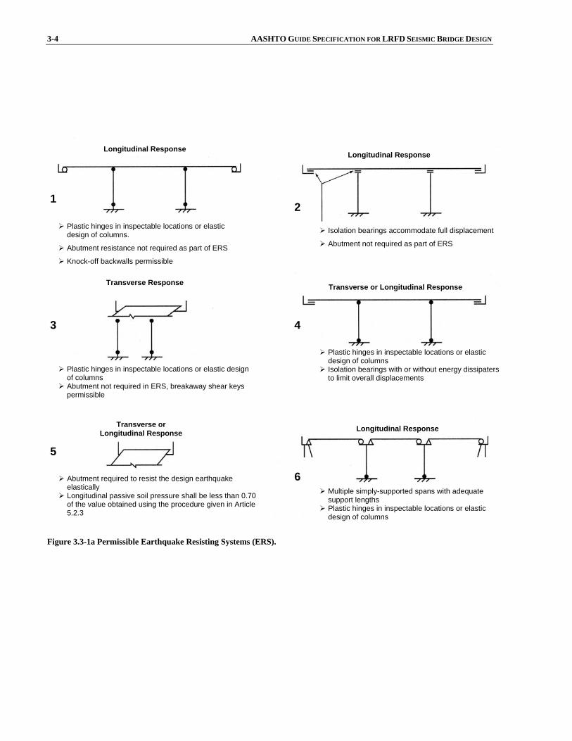
Figure 3.3-1a Permissible Earthquake Resisting Systems (ERS).
Abutment required to resist the design earthquake elastically
Longitudinal passive soil pressure shall be less than 0.70 of the value obtained using the procedure given in Article 5.2.3
Plastic hinges in inspectable locations or elastic design of columns.
Abutment resistance not required as part of ERS
Knock-off backwalls permissible
Longitudinal Response
Transverse Response
Transverse or Longitudinal Response
Plastic hinges in inspectable locations or elastic design of columns
Abutment not required in ERS, breakaway shear keys permissible
Longitudinal Response
Isolation bearings accommodate full displacement
Abutment not required as part of ERS
Plastic hinges in inspectable locations or elastic design of columns
Isolation bearings with or without energy dissipaters to limit overall displacements
Multiple simply-supported spans with adequate support lengths
Plastic hinges in inspectable locations or elastic design of columns
Transverse or Longitudinal Response
Longitudinal Response
1 2
3 4
5
6
SECTION 3: GENERAL REQUIREMENTS 3-5
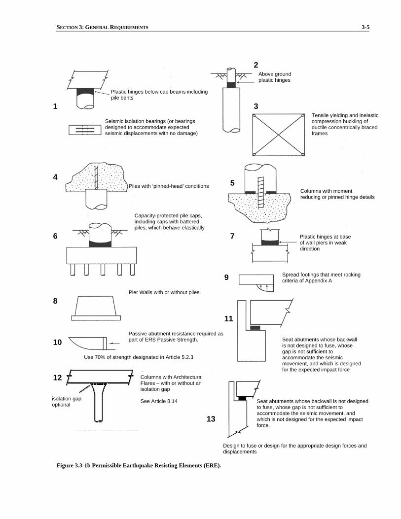
Figure 3.3-1b Permissible Earthquake Resisting Elements (ERE).
Columns with Architectural Flares – with or without an isolation gap See Article 8.14
Pier Walls with or without piles.
Spread footings that meet rocking criteria of Appendix A
Capacity-protected pile caps, including caps with battered piles, which behave elastically
Piles with ‘pinned-head’ conditions
Seismic isolation bearings (or bearings designed to accommodate expected seismic displacements with no damage)
Plastic hinges below cap beams including pile bents
Above ground plastic hinges
Tensile yielding and inelastic compression buckling of ductile concentrically braced frames
Plastic hinges at base of wall piers in weak direction
Seat abutments whose backwall is not designed to fuse, whose gap is not sufficient to accommodate the seismic movement, and which is designed for the expected impact force
Passive abutment resistance required as part of ERS Passive Strength.
Use 70% of strength designated in Article 5.2.3
isolation gap optional
Design to fuse or design for the appropriate design forces and displacements
1
2
3
4 5
6 7
8
9
10
11
12
13
Seat abutments whose backwall is not designed to fuse, whose gap is not sufficient to accommodate the seismic movement, and which is not designed for the expected impact force.
Columns with moment reducing or pinned hinge details
3-6 AASHTO GUIDE SPECIFICATION FOR LRFD SEISMIC BRIDGE DESIGN
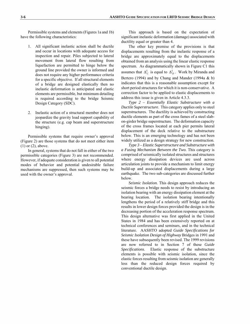
Permissible systems and elements (Figures 1a and 1b)have the following characteristics:
1. All significant inelastic action shall be ductile
and occur in locations with adequate access forinspection and repair. Piles subjected to lateralmovement from lateral flow resulting fromliquefaction are permitted to hinge below theground line provided the owner is informed anddoes not require any higher performance criteriafor a specific objective. If all structural elementsof a bridge are designed elastically then noinelastic deformation is anticipated and elasticelements are permissible, but minimum detailingis required according to the bridge SeismicDesign Category (SDC).
2. Inelastic action of a structural member does not
jeopardize the gravity load support capability of the structure (e.g. cap beam and superstructurehinging).
Permissible systems that require owner’s approval
(Figure 2) are those systems that do not meet either item(1) or (2), above.
In general, systems that do not fall in either of the twopermissible categories (Figure 3) are not recommended.However, if adequate consideration is given to all potentialmodes of behavior and potential undesirable failuremechanisms are suppressed, then such systems may beused with the owner’s approval.
This approach is based on the expectation of significant inelastic deformation (damage) associated with ductility equal or greater than 4.
The other key premise of the provisions is that displacements resulting from the inelastic response of a bridge are approximately equal to the displacements obtained from an analysis using the linear elastic response spectrum. As diagrammatically shown in Figure C1 this assumes that L
CΔ is equal to LDΔ . Work by Miranda and
Bertero (1994) and by Chang and Mander (1994a & b) indicates that this is a reasonable assumption except for short period structures for which it is non-conservative. A correction factor to be applied to elastic displacements to address this issue is given in Article 4.3.3.
Type 2 – Essentially Elastic Substructure with a Ductile Superstructure. This category applies only to steel superstructures. The ductility is achieved by constructing ductile elements as part of the cross fames of a steel slab-on-girder bridge superstructure. The deformation capacity of the cross frames located at each pier permits lateral displacement of the deck relative to the substructure below. This is an emerging technology and has not been widely utilized as a design strategy for new construction.
Type 3 – Elastic Superstructure and Substructure with a Fusing Mechanism Between the Two. This category is comprised of seismically isolated structures and structures where energy dissipation devices are used across articulation joints to provide a mechanism to limit energy build-up and associated displacements during a large earthquake. The two sub-categories are discussed further below.
Seismic Isolation. This design approach reduces the seismic forces a bridge needs to resist by introducing an isolation bearing with an energy dissipation element at the bearing location. The isolation bearing intentionally lengthens the period of a relatively stiff bridge and this results in lower design forces provided the design is in the decreasing portion of the acceleration response spectrum. This design alternative was first applied in the United States in 1984 and has been extensively reported on at technical conferences and seminars, and in the technical literature. AASHTO adopted Guide Specifications for Seismic Isolation Design of Highway Bridges in 1991 and these have subsequently been revised. The 1999 revisions are now referred to in Section 7 of these Guide Specifications. Elastic response of the substructure elements is possible with seismic isolation, since the elastic forces resulting from seismic isolation are generally less than the reduced design forces required by conventional ductile design.

SECTION 3: GENERAL REQUIREMENTS 3-7
Figure C3.3-1 Design Using Strategy Type 1.
3-8 AASHTO GUIDE SPECIFICATION FOR LRFD SEISMIC BRIDGE DESIGN
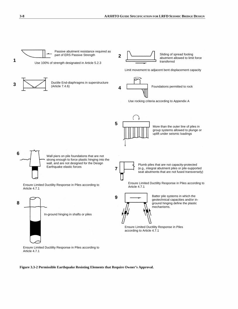
Figure 3.3-2 Permissible Earthquake Resisting Elements that Require Owner’s Approval.
and 8.5.2
Wall piers on pile foundations that are not strong enough to force plastic hinging into the wall, and are not designed for the Design Earthquake elastic forces
Passive abutment resistance required as part of ERS Passive Strength
Limit movement to adjacent bent displacement capacity
Use rocking criteria according to Appendix A
Foundations permitted to rock
Ensure Limited Ductility Response in Piles according to Article 4.7.1
Ensure Limited Ductility Response in Piles according to Article 4.7.1
Ensure Limited Ductility Response in Piles according to Article 4.7.1
Ensure Limited Ductility Response in Piles according to Article 4.7.1
Batter pile systems in which the geotechnical capacities and/or in-ground hinging define the plastic mechanisms.
Sliding of spread footing abutment allowed to limit force transferred
Ductile End-diaphragms in superstructure (Article 7.4.6)
More than the outer line of piles in group systems allowed to plunge or uplift under seismic loadings
Plumb piles that are not capacity-protected (e.g., integral abutment piles or pile-supported seat abutments that are not fused transversely)
In-ground hinging in shafts or piles
1 2
3 4
5
6
7
8 9
Use 100% of strength designated in Article 5.2.3

SECTION 3: GENERAL REQUIREMENTS 3-9
Figure 3.3-3 Earthquake Resisting Elements that are not Recommended for New Bridges.
Energy Dissipation. This design approach adds energy-dissipation elements between the superstructure and the substructure, and between the superstructure and abutment, with the intent of dissipating energy in these elements. This eliminates the need for the energy needing dissipation in the plastic hinge zones of columns. This design approach differs from seismic isolation in that additional flexibility is generally not part of the system and thus the fundamental period of vibration is not changed. If the equivalent viscous damping of the bridge is increased above 5% then the displacement of the superstructure will be reduced. In general the energy dissipation design concept does not result in reduced design forces but it will reduce the ductility demand on columns due to the reduction in superstructure displacement (ATC, 1993).
Abutments as an Additional Energy-Dissipation Mechanism. In the early phases of the development of the Specifications, there was serious debate as to whether or not the abutments would be included and relied upon in the earthquake resisting system (ERS). Some states may require the design of a bridge where the substructures are capable of resisting all the lateral load without any contribution from the abutments. In this design approach, the abutments are included in a mechanism to provide an unquantifiable higher level of safety. Rather than mandate this design philosophy here, it was decided to permit two design alternatives. The first is where the ERS does not include the abutments and the substructures are capable of resisting all the lateral loads. In the second alternative the abutments are an important part of the ERS and, in this case, a higher level of analysis is required. Furthermore,this design option requires a continuous superstructure to
Bearing systems that do not provide for the expected displacements and/or forces (e.g., rocker bearings)
Battered-pile systems that are not designed to fuse geotechnically or structurally by elements with adequate ductility capacity
Cap beam plastic hinging (particularly hinging that leads to vertical girder movement) also includes eccentric braced frames with girders supported by cap beams
Plastic hinges in superstructure
1 2
3 4
3-10 AASHTO GUIDE SPECIFICATION FOR LRFD SEISMIC BRIDGE DESIGN
deliver longitudinal forces to the abutment. If these conditions are satisfied, the abutments can be designed as part of the ERS and become an additional source for dissipating the bridge’s earthquake energy. In the longitudinal direction the abutment may be designed to resist the forces elastically utilizing the passive pressure of the backfill. In some cases the longitudinal displacement of the deck will cause larger soil movements in the abutment backfill, exceeding the passive pressures there. This requires a more refined analysis to determine the amount of expected movement. In the transverse direction the abutment is generally designed to resist the loads elastically. The design objective when abutments are relied upon to resist either longitudinal or transverse loads is either to minimize column sizes or reduce the ductility demand on the columns, accepting that damage may occur in the abutment.
The performance expectation is that inelastic deformation will occur in the columns as well as the abutments. If large ductility demands occur in the columns then the columns may need to be replaced. If large movements of the superstructure occur the abutment back-wall may be damaged and there may be some settlement of the abutment backfill. Large movements of the superstructure can be reduced with use of energy dissipators and isolation bearings at the abutments and at the tops of the columns. Replacement of columns can be avoided with the use of the control and reparability design approach ductility with the use of the seismic isolation design alternative to reduce the demand on the columns.
In general, the soil behind an abutment is capable of resisting substantial seismic forces that may be delivered through a continuous superstructure to the abutment. Furthermore, such soil may also substantially limit the overall movements that a bridge may experience. This is particularly so in the longitudinal direction of a straight bridge with little or no skew and with a continuous deck. The controversy with this design concept is the scenario of what may happen if there is significant abutment damage early in the earthquake ground-motion duration and if the columns rely on the abutment to resist some of the load. This would be a problem in a long-duration, high-magnitude (greater than magnitude 7), earthquake. Unless shock transmission units (STUs) are used, a bridge composed of multiple simply supported spans cannot effectively mobilize the abutments for resistance to longitudinal force. It is recommended that simply supported spans not rely on abutments for any seismic resistance.
Because structural redundancy is desirable (Buckle et al., 1987), good design practice dictates the use of the design alternative where the intermediate substructures, between the abutments, are designed to resist all seismic loads, if possible. This ensures that in the event abutment resistance becomes ineffective, the bridge will still be able to resist the earthquake forces and displacements. In such a situation, the abutments provide an increased margin against collapse. The same arguments can be made for
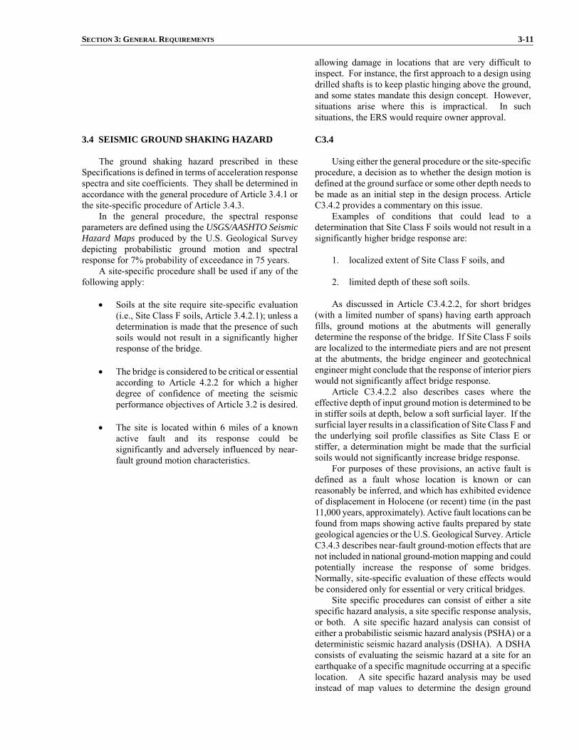
SECTION 3: GENERAL REQUIREMENTS 3-11
allowing damage in locations that are very difficult to inspect. For instance, the first approach to a design using drilled shafts is to keep plastic hinging above the ground, and some states mandate this design concept. However, situations arise where this is impractical. In such situations, the ERS would require owner approval.
3.4 SEISMIC GROUND SHAKING HAZARD
The ground shaking hazard prescribed in these
Specifications is defined in terms of acceleration response spectra and site coefficients. They shall be determined inaccordance with the general procedure of Article 3.4.1 orthe site-specific procedure of Article 3.4.3.
In the general procedure, the spectral responseparameters are defined using the USGS/AASHTO SeismicHazard Maps produced by the U.S. Geological Survey depicting probabilistic ground motion and spectralresponse for 7% probability of exceedance in 75 years.
A site-specific procedure shall be used if any of thefollowing apply:
• Soils at the site require site-specific evaluation
(i.e., Site Class F soils, Article 3.4.2.1); unless adetermination is made that the presence of suchsoils would not result in a significantly higherresponse of the bridge.
• The bridge is considered to be critical or essential according to Article 4.2.2 for which a higherdegree of confidence of meeting the seismicperformance objectives of Article 3.2 is desired.
• The site is located within 6 miles of a knownactive fault and its response could besignificantly and adversely influenced by near-fault ground motion characteristics.
C3.4 Using either the general procedure or the site-specific
procedure, a decision as to whether the design motion is defined at the ground surface or some other depth needs to be made as an initial step in the design process. Article C3.4.2 provides a commentary on this issue.
Examples of conditions that could lead to a determination that Site Class F soils would not result in a significantly higher bridge response are:
1. localized extent of Site Class F soils, and
2. limited depth of these soft soils.
As discussed in Article C3.4.2.2, for short bridges
(with a limited number of spans) having earth approach fills, ground motions at the abutments will generally determine the response of the bridge. If Site Class F soils are localized to the intermediate piers and are not present at the abutments, the bridge engineer and geotechnical engineer might conclude that the response of interior piers would not significantly affect bridge response.
Article C3.4.2.2 also describes cases where the effective depth of input ground motion is determined to be in stiffer soils at depth, below a soft surficial layer. If the surficial layer results in a classification of Site Class F and the underlying soil profile classifies as Site Class E or stiffer, a determination might be made that the surficial soils would not significantly increase bridge response.
For purposes of these provisions, an active fault is defined as a fault whose location is known or can reasonably be inferred, and which has exhibited evidence of displacement in Holocene (or recent) time (in the past 11,000 years, approximately). Active fault locations can be found from maps showing active faults prepared by state geological agencies or the U.S. Geological Survey. Article C3.4.3 describes near-fault ground-motion effects that are not included in national ground-motion mapping and could potentially increase the response of some bridges. Normally, site-specific evaluation of these effects would be considered only for essential or very critical bridges.
Site specific procedures can consist of either a site specific hazard analysis, a site specific response analysis, or both. A site specific hazard analysis can consist of either a probabilistic seismic hazard analysis (PSHA) or a deterministic seismic hazard analysis (DSHA). A DSHA consists of evaluating the seismic hazard at a site for an earthquake of a specific magnitude occurring at a specific location. A site specific hazard analysis may be used instead of map values to determine the design ground
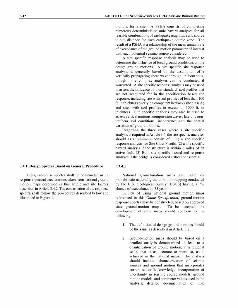
3-12 AASHTO GUIDE SPECIFICATION FOR LRFD SEISMIC BRIDGE DESIGN
motions for a site. A PSHA consists of completing numerous deterministic seismic hazard analyses for all feasible combinations of earthquake magnitude and source to site distance for each earthquake source zone. The result of a PSHA is a relationship of the mean annual rate of exceedance of the ground motion parameter of interest with each potential seismic source considered.
A site specific response analysis may be used to determine the influence of local ground conditions on the design ground motions. A site specific site response analysis is generally based on the assumption of a vertically propagating shear wave through uniform soils, though more complex analyses can be conducted if warranted. A site specific response analysis may be used to assess the influence of “non-standard” soil profiles that are not accounted for in the specification based site response, including site with soil profiles of less than 100 ft. in thickness overlying competent bedrock (site class A) and sites with soil profiles in excess of 1000 ft. in thickness. Site specific analyses may also be used to assess vertical motions, compression waves, laterally non-uniform soil conditions, incoherence and the spatial variation of ground motions.
Regarding the three cases where a site specific analysis is required in Article 3.4, the site specific analyses should as a minimum consist of: (1) a site specific response analysis for Site Class F soils, (2) a site specific hazard analysis if the structure is within 6 miles of an active fault, (3) Both site specific hazard and response analyses if the bridge is considered critical or essential.
3.4.1 Design Spectra Based on General Procedure
Design response spectra shall be constructed using
response spectral accelerations taken from national groundmotion maps described in this article and site factorsdescribed in Article 3.4.2. The construction of the response spectra shall follow the procedures described below andillustrated in Figure 1.
C3.4.1 National ground-motion maps are based on
probabilistic national ground motion mapping conducted by the U.S. Geological Survey (USGS) having a 7% chance of exceedance in 75 years.
In lieu of using national ground motion maps referenced in this Guide Specification, ground-motionresponse spectra may be constructed, based on approved state ground-motion maps. To be accepted, the development of state maps should conform to the following:
1. The definition of design ground motions should be the same as described in Article 3.2.
2. Ground-motion maps should be based on a
detailed analysis demonstrated to lead to a quantification of ground motion, at a regional scale, that is as accurate or more so, as is achieved in the national maps. The analysis should include: characterization of seismic sources and ground motion that incorporates current scientific knowledge; incorporation of uncertainty in seismic source models, ground motion models, and parameter values used in the analysis; detailed documentation of map

SECTION 3: GENERAL REQUIREMENTS 3-13
Figure 3.4.1-1 Design Response Spectrum, Construction Using Two-Point Method.
development; and detailed peer review as deemed appropriate by the Owner. The peer review process should preferably include one or more individuals from the U.S. Geological Survey who participated in the development of the national maps.
Design earthquake response spectral acceleration coefficient at short periods, SDS, and at 1 second period, SD1, shall be determined from Eqs. 1 and 2, respectively:
DS a sS = F S (3.4.1-1) where:
Fa = site coefficient for 0.2 second period spectral
acceleration specified in Article 3.4.2.3 Ss = 0.2 second period spectral acceleration
coefficient on Class B rock
D1 v 1S = F S (3.4.1-2) where: Fv = site coefficient for 1.0 second period spectral
acceleration specified in Article 3.4.2.3 S1 = 1.0 second period spectral acceleration
coefficient on Class B rock
Values of Ss and S1 may be obtained from groundmotion maps shown in Figures 2a through 22. Alternatively, they may also be obtained usingaccompanying CD-ROM to these Guide Specificationswhich contains electronic versions of the ground motionmaps.
The design response spectrum curve shall bedeveloped as follows and as indicated in Figure 1:
For periods exceeding approximately 3 seconds, depending on the seismic environment, Eq. 7 may be conservative because the ground motions may be approaching the constant spectral displacement range for which Sa decays with period as 1/T 2.
1. For periods less than or equal to To, the design response spectral acceleration coefficient, Sa, shall be defined as follows:
DSS40.0

3-14 AASHTO GUIDE SPECIFICATION FOR LRFD SEISMIC BRIDGE DESIGN
0.60 0.40DSa DS
o
SS T S
T= + (3.4.1-3)
in which: 0.2o ST T= (3.4.1-4)
DS
1DS S
ST = (3.4.1-5)
where:
SD1 = design spectral acceleration coefficient at 1.0 second period
SDS = design spectral acceleration coefficient at 0.2 second period
T = period of vibration (sec.)
Note that for T = 0 seconds, the resulting value of Sa is equal to 0.40SDS.
2. For periods greater than or equal to To and less
than or equal to TS, the design response spectralacceleration coefficient, Sa, shall be defined asfollows:
a DSS S= (3.4.1-6)
3. For periods greater than TS, the design response spectral acceleration coefficient, Sa, shall be defined as follows:
T
SS 1D
a = (3.4.1-7)
Response spectra constructed using maps and
procedures described in Article 3.4.1 are for a damping ratio of 5% and do not include near field adjustments.
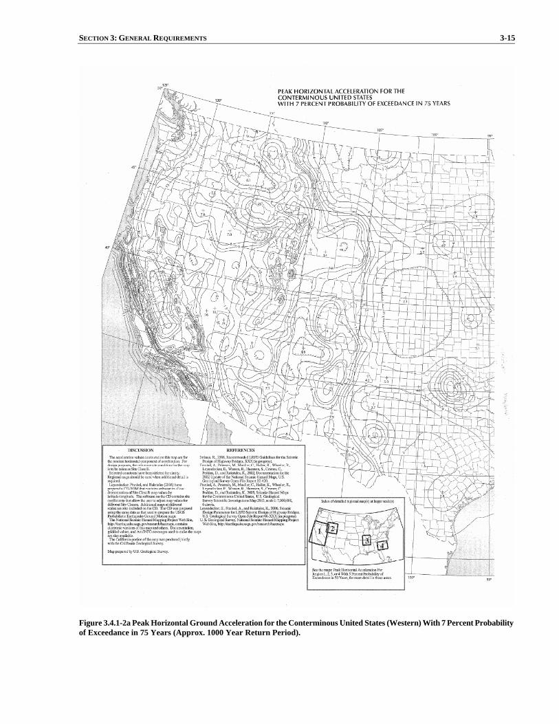
SECTION 3: GENERAL REQUIREMENTS 3-15
Figure 3.4.1-2a Peak Horizontal Ground Acceleration for the Conterminous United States (Western) With 7 Percent Probability of Exceedance in 75 Years (Approx. 1000 Year Return Period).

3-16 AASHTO GUIDE SPECIFICATION FOR LRFD SEISMIC BRIDGE DESIGN
Figure 3.4.1-2b Peak Horizontal Ground Acceleration for the Conterminous United States (Eastern) With 7 Percent Probability of Exceedance in 75 Years (Approx. 1000 Year Return Period).

SECTION 3: GENERAL REQUIREMENTS 3-17
Figure 3.4.1-3a Horizontal Response Spectral Acceleration for the Conterminous United States (Western) at Period of 0.2 Seconds (Ss) With 7 Percent Probability of Exceedance in 75 Years (Approx. 1000 Year Return Period) and 5 Percent Critical Damping.

3-18 AASHTO GUIDE SPECIFICATION FOR LRFD SEISMIC BRIDGE DESIGN
Figure 3.4.1-3b Horizontal Response Spectral Acceleration for the Conterminous United States (Eastern) at Period of 0.2 Seconds (Ss) With 7 Percent Probability of Exceedance in 75 Years (Approx. 1000 Year Return Period) and 5 Percent Critical Damping.
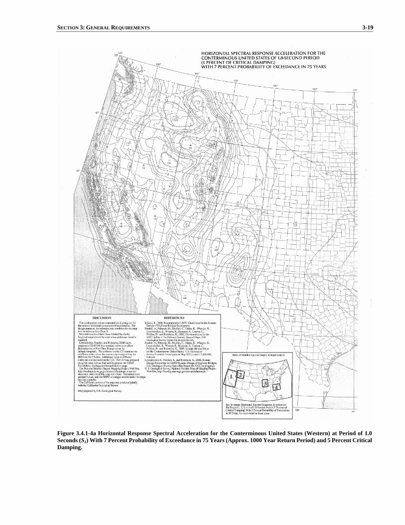
SECTION 3: GENERAL REQUIREMENTS 3-19
Figure 3.4.1-4a Horizontal Response Spectral Acceleration for the Conterminous United States (Western) at Period of 1.0 Seconds (S1) With 7 Percent Probability of Exceedance in 75 Years (Approx. 1000 Year Return Period) and 5 Percent Critical Damping.

3-20 AASHTO GUIDE SPECIFICATION FOR LRFD SEISMIC BRIDGE DESIGN
Figure 3.4.1-4b Horizontal Response Spectral Acceleration for the Conterminous United States (Eastern) at Period of 1.0 Seconds (S1) With 7 Percent Probability of Exceedance in 75 Years (Approx. 1000 Year Return Period) and 5 Percent Critical Damping.
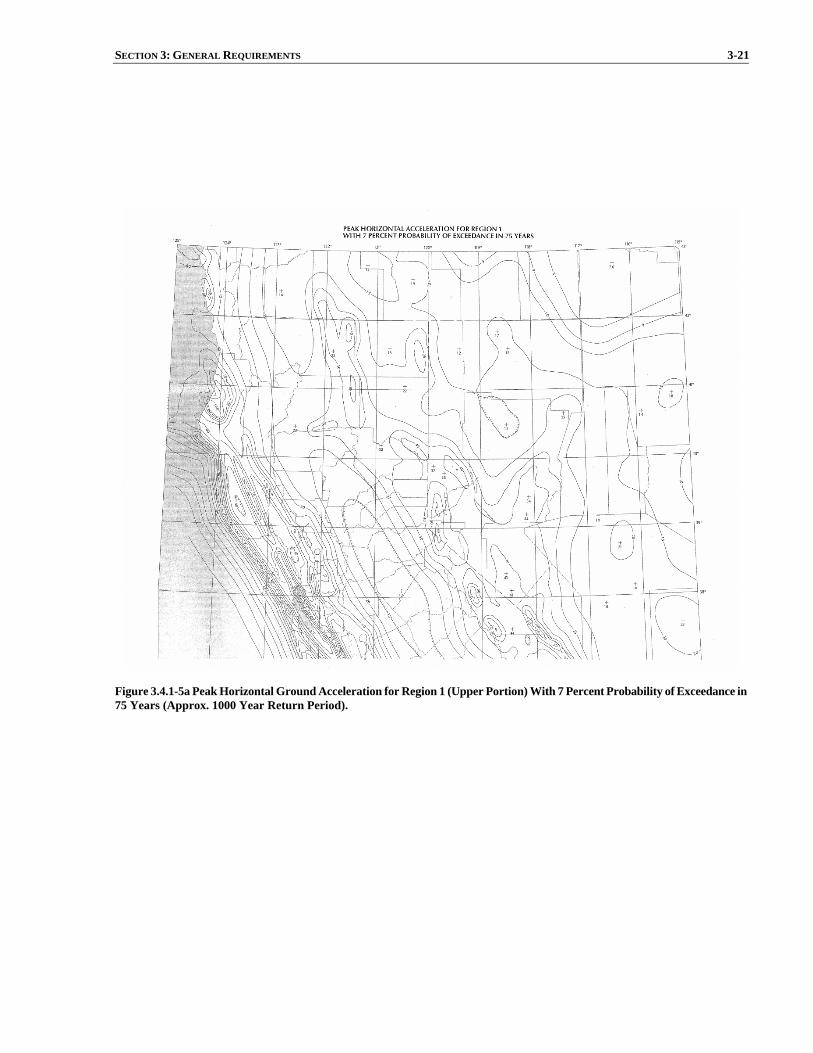
SECTION 3: GENERAL REQUIREMENTS 3-21
Figure 3.4.1-5a Peak Horizontal Ground Acceleration for Region 1 (Upper Portion) With 7 Percent Probability of Exceedance in 75 Years (Approx. 1000 Year Return Period).

3-22 AASHTO GUIDE SPECIFICATION FOR LRFD SEISMIC BRIDGE DESIGN
Figure 3.4.1- 5b Peak Horizontal Ground Acceleration for Region 1 (Lower Portion) With 7 Percent Probability of Exceedance in 75 Years (Approx. 1000 Year Return Period).

SECTION 3: GENERAL REQUIREMENTS 3-23
Figure 3.4.1-6a Horizontal Response Spectral Acceleration for Region 1 (Upper Portion) at Period of 0.2 Seconds (Ss) With 7 Percent Probability of Exceedance in 75 Years (Approx. 1000 Year Return Period) and 5 Percent Critical Damping.
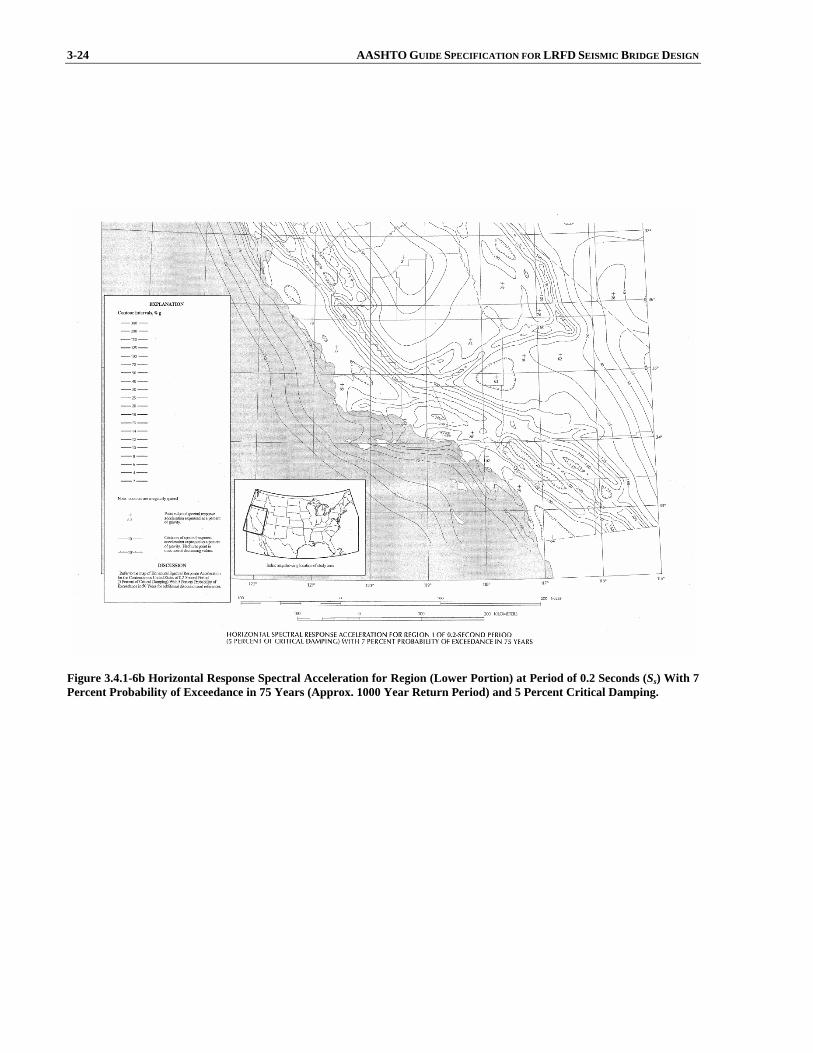
3-24 AASHTO GUIDE SPECIFICATION FOR LRFD SEISMIC BRIDGE DESIGN
Figure 3.4.1-6b Horizontal Response Spectral Acceleration for Region (Lower Portion) at Period of 0.2 Seconds (Ss) With 7 Percent Probability of Exceedance in 75 Years (Approx. 1000 Year Return Period) and 5 Percent Critical Damping.

SECTION 3: GENERAL REQUIREMENTS 3-25
Figure 3.4.1-7a Horizontal Response Spectral Acceleration for Region 1 (Upper Portion) at Period of 1.0 Seconds (S1) With 7 Percent Probability of Exceedance in 75 Years (Approx. 1000 Year Return Period) and 5 Percent Critical Damping.
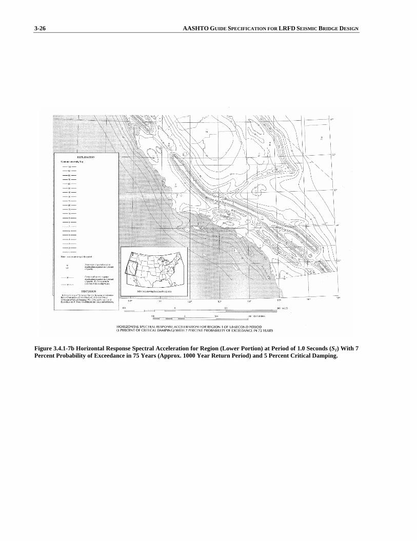
3-26 AASHTO GUIDE SPECIFICATION FOR LRFD SEISMIC BRIDGE DESIGN
Figure 3.4.1-7b Horizontal Response Spectral Acceleration for Region (Lower Portion) at Period of 1.0 Seconds (S1) With 7 Percent Probability of Exceedance in 75 Years (Approx. 1000 Year Return Period) and 5 Percent Critical Damping.

SECTION 3: GENERAL REQUIREMENTS 3-27
Figure 3.4.1-8 Peak Horizontal Ground Acceleration for Region 2 With 7 Percent Probability of Exceedance in 75 Years (Approx. 1000 Year Return Period).
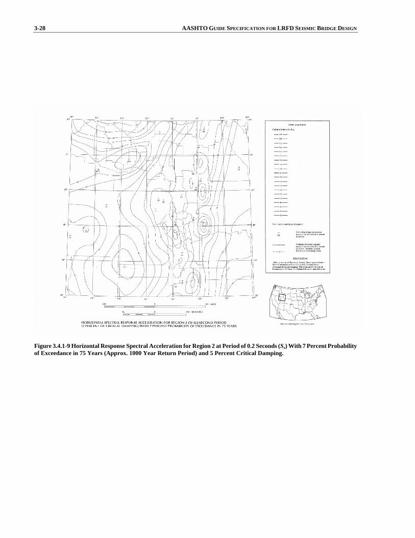
3-28 AASHTO GUIDE SPECIFICATION FOR LRFD SEISMIC BRIDGE DESIGN
Figure 3.4.1-9 Horizontal Response Spectral Acceleration for Region 2 at Period of 0.2 Seconds (Ss) With 7 Percent Probability of Exceedance in 75 Years (Approx. 1000 Year Return Period) and 5 Percent Critical Damping.

SECTION 3: GENERAL REQUIREMENTS 3-29
Figure 3.4.1-10 Horizontal Response Spectral Acceleration for Region 2 at Period of 1.0 Seconds (S1) With 7 Percent Probability of Exceedance in 75 Years (Approx. 1000 Year Return Period) and 5 Percent Critical Damping.
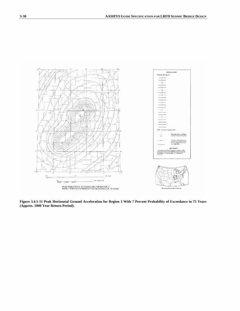
3-30 AASHTO GUIDE SPECIFICATION FOR LRFD SEISMIC BRIDGE DESIGN
Figure 3.4.1-11 Peak Horizontal Ground Acceleration for Region 3 With 7 Percent Probability of Exceedance in 75 Years (Approx. 1000 Year Return Period).

SECTION 3: GENERAL REQUIREMENTS 3-31
Figure 3.4.1-12 Horizontal Response Spectral Acceleration for Region 3 at Period of 0.2 Seconds (Ss) With 7 Percent Probability of Exceedance in 75 Years (Approx. 1000 Year Return Period) and 5 Percent Critical Damping.

3-32 AASHTO GUIDE SPECIFICATION FOR LRFD SEISMIC BRIDGE DESIGN
Figure 3.4.1-13 Horizontal Response Spectral Acceleration for Region 3 at Period of 1.0 Seconds (S1) With 7 Percent Probability of Exceedance in 75 Years (Approx. 1000 Year Return Period) and 5 Percent Critical Damping.

SECTION 3: GENERAL REQUIREMENTS 3-33
Figure 3.4.1-14 Peak Horizontal Ground Acceleration for Region 4 With 7 Percent Probability of Exceedance in 75 Years (Approx. 1000 Year Return Period).

3-34 AASHTO GUIDE SPECIFICATION FOR LRFD SEISMIC BRIDGE DESIGN
Figure 3.4.1-15 Horizontal Response Spectral Acceleration for Region 4 at Periods of 0.2 and 1.0 Seconds (Ss and S1) With 7 Percent Probability of Exceedance in 75 Years (Approx. 1000 Year Return Period) and 5 Percent Critical Damping.

SECTION 3: GENERAL REQUIREMENTS 3-35
Figure 3.4.1-16 Peak Horizontal Ground Acceleration for Alaska With 7 Percent Probability of Exceedance in 75 Years (Approx. 1000 Year Return Period).
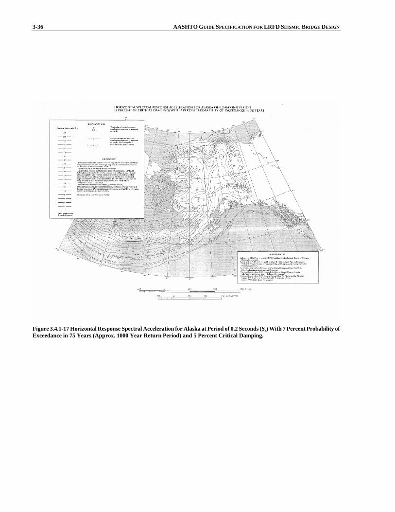
3-36 AASHTO GUIDE SPECIFICATION FOR LRFD SEISMIC BRIDGE DESIGN
Figure 3.4.1-17 Horizontal Response Spectral Acceleration for Alaska at Period of 0.2 Seconds (Ss) With 7 Percent Probability of Exceedance in 75 Years (Approx. 1000 Year Return Period) and 5 Percent Critical Damping.
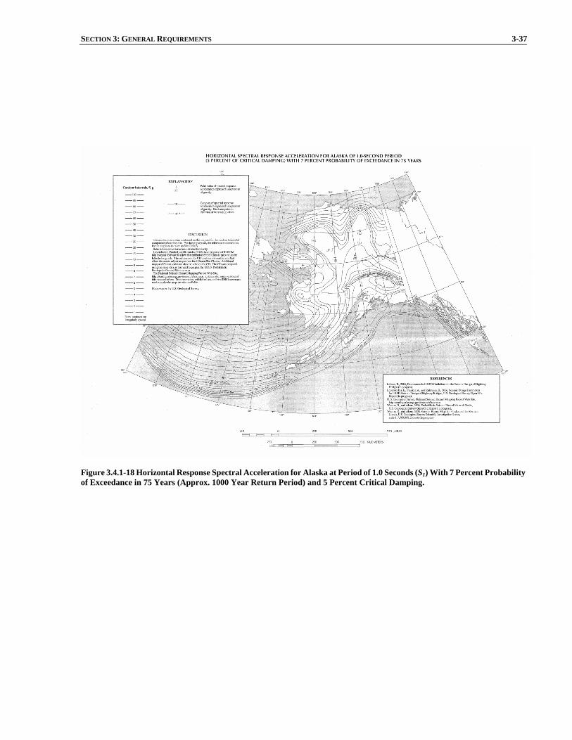
SECTION 3: GENERAL REQUIREMENTS 3-37
Figure 3.4.1-18 Horizontal Response Spectral Acceleration for Alaska at Period of 1.0 Seconds (S1) With 7 Percent Probability of Exceedance in 75 Years (Approx. 1000 Year Return Period) and 5 Percent Critical Damping.

3-38 AASHTO GUIDE SPECIFICATION FOR LRFD SEISMIC BRIDGE DESIGN
Figure 3.4.1-19 Peak Horizontal Ground Acceleration for Hawaii With 7 Percent Probability of Exceedance in 75 Years (Approx. 1000 Year Return Period).

SECTION 3: GENERAL REQUIREMENTS 3-39
Figure 3.4.1-20 Horizontal Response Spectral Acceleration for Hawaii at Periods of 0.2 and 1.0 Seconds (Ss and S1) With 7 Percent Probability of Exceedance in 75 Years (Approx. 1000 Year Return Period) and 5 Percent Critical Damping.

3-40 AASHTO GUIDE SPECIFICATION FOR LRFD SEISMIC BRIDGE DESIGN
Figure 3.4.1-21 Peak Horizontal Ground Acceleration for Puerto Rico, Culebra, Vieques, St. Thomas, St. John, and St. Croix With 7 Percent Probability of Exceedance in 75 Years (Approx. 1000 Year Return Period).
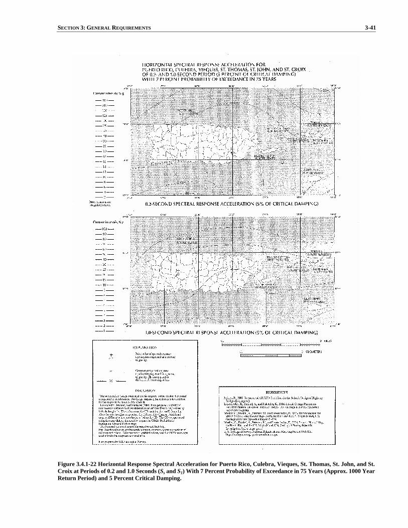
SECTION 3: GENERAL REQUIREMENTS 3-41
Figure 3.4.1-22 Horizontal Response Spectral Acceleration for Puerto Rico, Culebra, Vieques, St. Thomas, St. John, and St. Croix at Periods of 0.2 and 1.0 Seconds (Ss and S1) With 7 Percent Probability of Exceedance in 75 Years (Approx. 1000 Year Return Period) and 5 Percent Critical Damping.
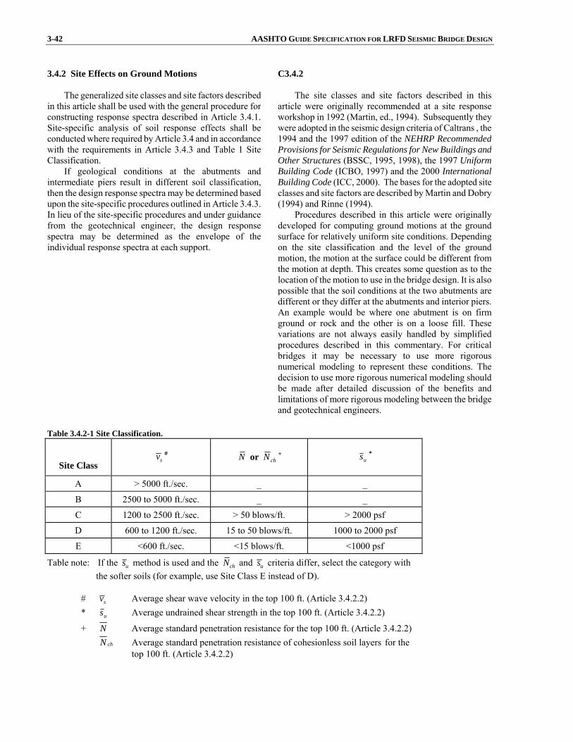
3-42 AASHTO GUIDE SPECIFICATION FOR LRFD SEISMIC BRIDGE DESIGN 3.4.2 Site Effects on Ground Motions
The generalized site classes and site factors described
in this article shall be used with the general procedure forconstructing response spectra described in Article 3.4.1.Site-specific analysis of soil response effects shall beconducted where required by Article 3.4 and in accordancewith the requirements in Article 3.4.3 and Table 1 SiteClassification.
If geological conditions at the abutments andintermediate piers result in different soil classification, then the design response spectra may be determined basedupon the site-specific procedures outlined in Article 3.4.3.In lieu of the site-specific procedures and under guidancefrom the geotechnical engineer, the design responsespectra may be determined as the envelope of theindividual response spectra at each support.
C3.4.2 The site classes and site factors described in this
article were originally recommended at a site response workshop in 1992 (Martin, ed., 1994). Subsequently they were adopted in the seismic design criteria of Caltrans , the 1994 and the 1997 edition of the NEHRP Recommended Provisions for Seismic Regulations for New Buildings and Other Structures (BSSC, 1995, 1998), the 1997 Uniform Building Code (ICBO, 1997) and the 2000 International Building Code (ICC, 2000). The bases for the adopted site classes and site factors are described by Martin and Dobry (1994) and Rinne (1994).
Procedures described in this article were originally developed for computing ground motions at the ground surface for relatively uniform site conditions. Depending on the site classification and the level of the ground motion, the motion at the surface could be different from the motion at depth. This creates some question as to the location of the motion to use in the bridge design. It is also possible that the soil conditions at the two abutments are different or they differ at the abutments and interior piers. An example would be where one abutment is on firm ground or rock and the other is on a loose fill. These variations are not always easily handled by simplified procedures described in this commentary. For critical bridges it may be necessary to use more rigorous numerical modeling to represent these conditions. The decision to use more rigorous numerical modeling should be made after detailed discussion of the benefits and limitations of more rigorous modeling between the bridge and geotechnical engineers.
Table 3.4.2-1 Site Classification.
Site Class sv # N or chN +
us *
A > 5000 ft./sec. _ _
B 2500 to 5000 ft./sec. _ _
C 1200 to 2500 ft./sec. > 50 blows/ft. > 2000 psf
D 600 to 1200 ft./sec. 15 to 50 blows/ft. 1000 to 2000 psf
E <600 ft./sec. <15 blows/ft. <1000 psf
Table note: If the us method is used and the chN and us criteria differ, select the category with the softer soils (for example, use Site Class E instead of D).
# sv Average shear wave velocity in the top 100 ft. (Article 3.4.2.2) * us Average undrained shear strength in the top 100 ft. (Article 3.4.2.2)
+ N Average standard penetration resistance for the top 100 ft. (Article 3.4.2.2) chN Average standard penetration resistance of cohesionless soil layers for the
top 100 ft. (Article 3.4.2.2)
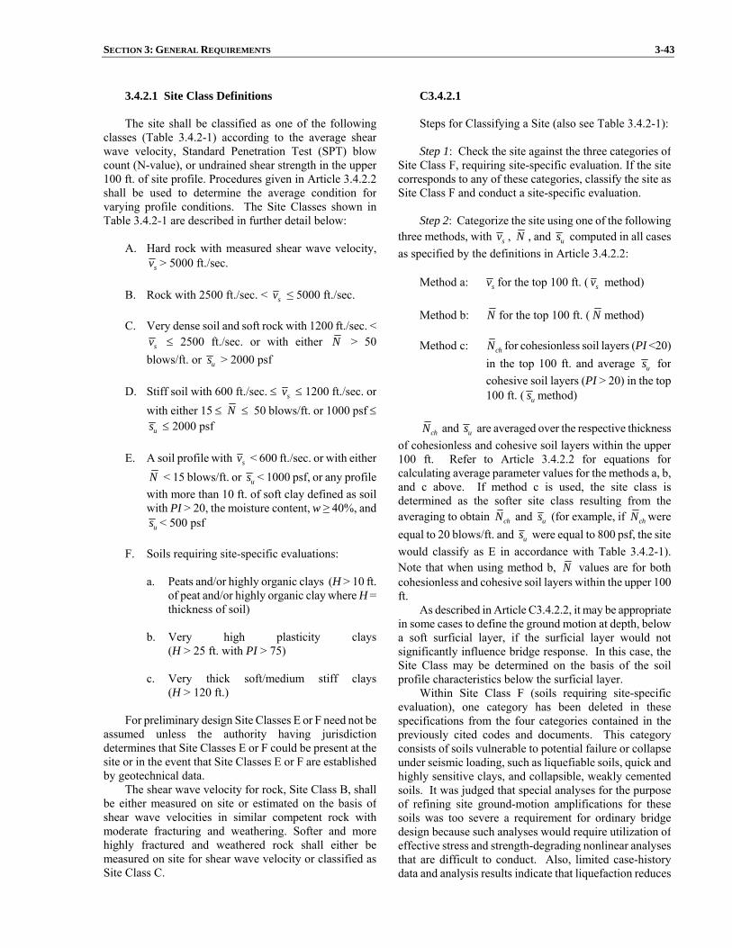
SECTION 3: GENERAL REQUIREMENTS 3-43
3.4.2.1 Site Class Definitions The site shall be classified as one of the following
classes (Table 3.4.2-1) according to the average shearwave velocity, Standard Penetration Test (SPT) blowcount (N-value), or undrained shear strength in the upper100 ft. of site profile. Procedures given in Article 3.4.2.2shall be used to determine the average condition for varying profile conditions. The Site Classes shown in Table 3.4.2-1 are described in further detail below:
A. Hard rock with measured shear wave velocity,
sv > 5000 ft./sec.
B. Rock with 2500 ft./sec. < sv ≤ 5000 ft./sec.
C. Very dense soil and soft rock with 1200 ft./sec. < sv ≤ 2500 ft./sec. or with either N > 50
blows/ft. or us > 2000 psf
D. Stiff soil with 600 ft./sec. ≤ sv ≤ 1200 ft./sec. or with either 15 ≤ N ≤ 50 blows/ft. or 1000 psf ≤
us ≤ 2000 psf
E. A soil profile with sv < 600 ft./sec. or with either N < 15 blows/ft. or us < 1000 psf, or any profilewith more than 10 ft. of soft clay defined as soil with PI > 20, the moisture content, w ≥ 40%, and
us < 500 psf
F. Soils requiring site-specific evaluations: a. Peats and/or highly organic clays (H > 10 ft.
of peat and/or highly organic clay where H = thickness of soil)
b. Very high plasticity clays
(H > 25 ft. with PI > 75)
c. Very thick soft/medium stiff clays(H > 120 ft.)
For preliminary design Site Classes E or F need not be
assumed unless the authority having jurisdiction determines that Site Classes E or F could be present at thesite or in the event that Site Classes E or F are establishedby geotechnical data.
The shear wave velocity for rock, Site Class B, shall be either measured on site or estimated on the basis ofshear wave velocities in similar competent rock withmoderate fracturing and weathering. Softer and more highly fractured and weathered rock shall either bemeasured on site for shear wave velocity or classified asSite Class C.
C3.4.2.1 Steps for Classifying a Site (also see Table 3.4.2-1): Step 1: Check the site against the three categories of
Site Class F, requiring site-specific evaluation. If the site corresponds to any of these categories, classify the site as Site Class F and conduct a site-specific evaluation.
Step 2: Categorize the site using one of the following
three methods, with sv , N , and us computed in all cases as specified by the definitions in Article 3.4.2.2:
Method a: sv for the top 100 ft. ( sv method) Method b: N for the top 100 ft. ( N method) Method c: chN for cohesionless soil layers (PI <20)
in the top 100 ft. and average us for cohesive soil layers (PI > 20) in the top 100 ft. ( us method)
chN and us are averaged over the respective thickness
of cohesionless and cohesive soil layers within the upper 100 ft. Refer to Article 3.4.2.2 for equations for calculating average parameter values for the methods a, b, and c above. If method c is used, the site class is determined as the softer site class resulting from the averaging to obtain chN and us (for example, if chN were equal to 20 blows/ft. and us were equal to 800 psf, the site would classify as E in accordance with Table 3.4.2-1). Note that when using method b, N values are for both cohesionless and cohesive soil layers within the upper 100 ft.
As described in Article C3.4.2.2, it may be appropriate in some cases to define the ground motion at depth, below a soft surficial layer, if the surficial layer would not significantly influence bridge response. In this case, the Site Class may be determined on the basis of the soil profile characteristics below the surficial layer.
Within Site Class F (soils requiring site-specific evaluation), one category has been deleted in these specifications from the four categories contained in the previously cited codes and documents. This category consists of soils vulnerable to potential failure or collapse under seismic loading, such as liquefiable soils, quick and highly sensitive clays, and collapsible, weakly cemented soils. It was judged that special analyses for the purpose of refining site ground-motion amplifications for these soils was too severe a requirement for ordinary bridge design because such analyses would require utilization of effective stress and strength-degrading nonlinear analyses that are difficult to conduct. Also, limited case-history data and analysis results indicate that liquefaction reduces
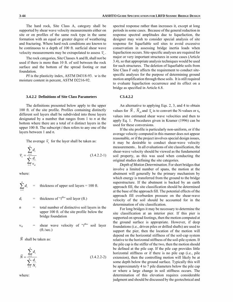
3-44 AASHTO GUIDE SPECIFICATION FOR LRFD SEISMIC BRIDGE DESIGN
The hard rock, Site Class A, category shall besupported by shear wave velocity measurements either on site or on profiles of the same rock type in the sameformation with an equal or greater degree of weatheringand fracturing. Where hard rock conditions are known tobe continuous to a depth of 100 ft. surficial shear wavevelocity measurements may be extrapolated to assess sv .
The rock categories, Site Classes A and B, shall not beused if there is more than 10 ft. of soil between the rocksurface and the bottom of the spread footing or matfoundation.
PI is the plasticity index, ASTM D4318-93. w is the moisture content in percent, ASTM D2216-92.
spectral response rather than increases it, except at long periods in some cases. Because of the general reduction in response spectral amplitudes due to liquefaction, the designer may wish to consider special analysis of site response for liquefiable soil sites to avoid excessive conservatism in assessing bridge inertia loads when liquefaction occurs. Site-specific analyses are required for major or very important structures in some cases (Article 3.4), so that appropriate analysis techniques would be used for such structures. The deletion of liquefiable soils from Site Class F only affects the requirement to conduct site-specific analyses for the purpose of determining ground motion amplification through these soils. It is still required to evaluate liquefaction occurrence and its effect on a bridge as specified in Article 6.8.
3.4.2.2 Definitions of Site Class Parameters The definitions presented below apply to the upper
100 ft. of the site profile. Profiles containing distinctly different soil layers shall be subdivided into those layersdesignated by a number that ranges from 1 to n at the bottom where there are a total of n distinct layers in theupper 100 ft. The subscript i then refers to any one of thelayers between 1 and n.
The average sv for the layer shall be taken as:
1
1
n
ii
s ni
i si
dv
dv
=
=
=∑
∑ (3.4.2.2-1)
where:
1
n
ii
d=∑ = thickness of upper soil layers = 100 ft.
di = thickness of “ith” soil layer (ft.) n = total number of distinctive soil layers in the upper 100 ft. of the site profile below the bridge foundation νsi = shear wave velocity of “ith” soil layer
(ft./sec.)
N shall be taken as:
1
1
n
iin
i
i i
dN
dN
=
=
=∑
∑ (3.4.2.2-2)
where:
C3.4.2.2 An alternative to applying Eqs. 2, 3, and 4 to obtain
values for N , chN and us is to convert the N-values or su
values into estimated shear wave velocities and then to apply Eq. 1. Procedures given in Kramer (1996) can be used for these conversions.
If the site profile is particularly non-uniform, or if the average velocity computed in this manner does not appear reasonable, or if the project involves special design issues, it may be desirable to conduct shear-wave velocity measurements.. In all evaluations of site classification, the shear-wave velocity should be viewed as the fundamental soil property, as this was used when conducting the original studies defining the site categories.
Depth of Motion Determination. For short bridges that involve a limited number of spans, the motion at the abutment will generally be the primary mechanism by which energy is transferred from the ground to the bridge superstructure. If the abutment is backed by an earth approach fill, the site classification should be determined at the base of the approach fill. The potential effects of the approach fill overburden pressure on the shear-wave velocity of the soil should be accounted for in the determination of site classification.
For long bridges it may be necessary to determine the site classification at an interior pier. If this pier is supported on spread footings, then the motion computed at the ground surface is appropriate. However, if deep foundations (i.e., driven piles or drilled shafts) are used to support the pier, then the location of the motion will depend on the horizontal stiffness of the soil-cap system relative to the horizontal stiffness of the soil-pile system. If the pile cap is the stiffer of the two, then the motion should be defined at the pile cap. If the pile cap provides little horizontal stiffness or if there is no pile cap (i.e., pile extension), then the controlling motion will likely be at some depth below the ground surface. Typically this will be approximately 4 to 7 pile diameters below the pile cap or where a large change in soil stiffness occurs. The determination of this elevation requires considerable judgment and should be discussed by the geotechnical and

SECTION 3: GENERAL REQUIREMENTS 3-45 Ni = standard penetration resistance as measured
directly in the filed, uncorrected blow count, of“ith” soil layer not to exceed 100 (blows/ft.)
chN shall be taken as:
1
1
m
ii
ch mi
i i
dN
dN
=
=
=∑
∑ (3.4.2.2-3)
where: m = total number of cohesionless soil layers in the
upper 100 ft. of the site profile below the bridgefoundation
us shall be taken as:
1
1
k
ii
u ki
i ui
ds
ds
=
=
=∑
∑ (3.4.2.2-4)
where: k = total number of cohesive soil layers in the upper
100 ft. of the site profile below the bridgefoundation
sui = undrained shear strength of “ith” soil layer not to
exceed 5 (ksf)
bridge engineers. For cases where the controlling motion is more
appropriately specified at depth, site-specific ground response analyses can be conducted to establish ground motions at the point of fixity. This approach or alternatives to this approach should be used only with the owner’s approval.
3.4.2.3 Site Coefficients Site coefficients for the short-period range (Fa) and for
the long-period range (Fv) are given in Tables 1 and 2,respectively. Application of these coefficients to determineelastic seismic response coefficients of ground motion isdescribed in Article 3.4.1.

3-46 AASHTO GUIDE SPECIFICATION FOR LRFD SEISMIC BRIDGE DESIGN Table 3.4.2.3-1 Values of Fa as a Function of Site Class and Mapped Short-Period Spectral Acceleration Coefficient.
Mapped Spectral Response Acceleration Coefficient at Short Periods
Site Class Ss ≤ 0.25 Ss = 0.50 Ss = 0.75 Ss = 1.00 Ss ≥ 1.25
A 0.8 0.8 0.8 0.8 0.8
B 1.0 1.0 1.0 1.0 1.0
C 1.2 1.2 1.1 1.0 1.0
D 1.6 1.4 1.2 1.1 1.0
E 2.5 1.7 1.2 0.9 0.9
F a a a a a
Table notes: Use straight line interpolation for intermediate values of Ss, where Ss is the spectral acceleration coefficient at 0.2 sec. obtained from the ground motion maps. a: Site-specific geotechnical investigation and dynamic site response analyses shall be performed (Article 3.4.3).
Table 3.4.2.3-2 Values of Fv as a Function of Site Class and Mapped 1 Second Period Spectral Acceleration Coefficient.
Mapped Spectral Response Acceleration Coefficient at 1 Second Periods
Site Class S1 ≤ 0.1 S1 = 0.2 S1 = 0.3 S1 = 0.4 S1 ≥ 0.5
A 0.8 0.8 0.8 0.8 0.8
B 1.0 1.0 1.0 1.0 1.0
C 1.7 1.6 1.5 1.4 1.3
D 2.4 2.0 1.8 1.6 1.5
E 3.5 3.2 2.8 2.4 2.4
F a a a a a
Table notes: Use straight line interpolation for intermediate values of S1, where S1 is the spectral acceleration coefficient at 1.0 sec. obtained from the ground motion maps. a: Site-specific geotechnical investigation and dynamic site response analyses shall be performed (Article 3.4.3).
3.4.3 Response Spectra Based on Site-Specific Procedures
A site-specific procedure to develop design response
spectra of earthquake ground motions shall be performed when required by Article 3.4 and may be performed forany site. The objective of the site-specific probabilisticground-motion analysis is to generate a uniform-hazard acceleration response spectrum considering a 7%probability of exceedance in 75 years for spectral valuesover the entire period range of interest. This analysis involves establishing:
C3.4.3 The intent in conducting a site-specific probabilistic
ground motion study is to develop ground motions that are more accurate for the local seismic and site conditions than can be determined from national ground motion maps and the procedure of Article 3.4.1. Accordingly, such studies should be comprehensive and incorporate current scientific interpretations at a regional scale. Because there are typically scientifically credible alternatives for models and parameter values used to characterize seismic sources and ground-motion attenuation, it is important to incorporate

SECTION 3: GENERAL REQUIREMENTS 3-47
1. The contributing seismic sources,
2. An upper-bound earthquake magnitude for eachsource zone,
3. Median attenuation relations for acceleration
response spectral values and their associatedstandard deviations,
4. A magnitude-recurrence relation for each source
zone, and
5. A fault-rupture-length relation for each contributing fault.
Uncertainties in source modeling and parameter
values shall be taken into consideration. Detaileddocumentation of ground-motion analysis is required andshall be peer reviewed (Article C3.4.1).
Where analyses to determine site soil response effectsare required by Articles 3.4 and 3.4.2.1 for Site Class Fsoils, the influence of the local soil conditions shall be determined based on site-specific geotechnical investigations and dynamic site response analyses.
For sites located within 6 miles of an active surface orshallow fault, as depicted in the USGS Active Fault Map,studies shall be considered to quantify near-fault effects on ground motions to determine if these could significantly influence the bridge response. The fault-normal component of near-field (D < 6 miles) motion may contain relatively long-duration velocity pulses which can causesevere nonlinear structural response, predictable onlythrough nonlinear time-history analyses. For this case therecorded near-field horizontal components of motion needto be transformed into principal components beforemodifying them to be response-spectrum-compatible.
A deterministic spectrum may be utilized in regions having known active faults if the deterministic spectrum isno less than 2/3 of the probabilistic spectrum in the regionof 0.5TF to 2TF of the spectrum where TF is the bridge fundamental period. The deterministic spectrum shall bethe envelope of a median spectra calculated forcharacteristic maximum magnitude earthquakes on knownactive faults. Alternatively, deterministic spectra may be defined for each fault, and each spectrum, or the spectrumthat governs bridge response should be used.
When response spectra are determined from a site-specific study, the spectra shall not be lower than two-thirds of the response spectra determined using the generalprocedure of Article 3.4.1 in the region of 0.5TF to 2TF of the spectrum where TF is the bridge fundamental period.
these uncertainties formally in a site-specific probabilistic analysis. Examples of these uncertainties include seismic source location, extent and geometry; maximum earthquake magnitude; earthquake recurrence rate; and ground-motion attenuation relationship.
Near-fault effects on horizontal response spectra
include: 1. Higher ground motions due to the proximity of
the active fault,
2. Directivity effects that increase ground motions for periods greater than 0.5 second if the fault rupture propagates toward the site, and
3. Directionality effects that increase ground
motions for periods greater than 0.5 second in the direction normal (perpendicular) to the strike of the fault.
If the active fault is included and appropriately
modeled in the development of national ground motionmaps, then effect (1) is already included in the national ground motion maps. Effects (2) and (3) are not included in the national maps. These effects are significant only for periods longer than 0.5 second and normally would be evaluated only for essential or critical bridges having natural periods of vibration longer than 0.5 second.Further discussion of effects (2) and (3) are contained in Somerville (1997) and Somerville et al. (1997). The ratio of vertical-to-horizontal ground motions increases for short-period motions in the near-fault environment.
3.4.4 Acceleration Time-Histories
The development of time histories shall meet the
requirements of this article. The developed time historiesshall have characteristics that are representative of the
C3.4.4 Characteristics of the seismic environment of the site
to be considered in selecting time-histories include: tectonic environment (e.g., subduction zone; shallow

3-48 AASHTO GUIDE SPECIFICATION FOR LRFD SEISMIC BRIDGE DESIGN seismic environment of the site and the local siteconditions.
Response-spectrum-compatible time histories shall beused as developed from representative recorded motions.Analytical techniques used for spectrum matching shall bedemonstrated to be capable of achieving seismologically realistic time series that are similar to the time series of theinitial time histories selected for spectrum matching.
When using recorded time histories, they shall bescaled to the approximate level of the design response spectrum in the period range of significance. Each timehistory shall be modified to be response-spectrumcompatible using the time-domain procedure.
At least three response-spectrum-compatible timehistories shall be used for each component of motion inrepresenting the design earthquake (ground motions having 7% probability of exceedance in 75 years). Theissue of requiring all three orthogonal components (x, y, and z) of design motion to be input simultaneously shall beconsidered as a requirement when conducting a nonlineartime-history analysis. The design actions shall be taken asthe maximum response calculated for the three ground motions in each principal direction. If a minimum ofseven time histories are used for each component ofmotion, the design actions may be taken as the meanresponse calculated for each principal direction.
For near-field sites (D < 6 miles) the recorded horizontal components of motion selected should representa near-field condition and that they should be transformed into principal components before making them response-spectrum-compatible. The major principal component should then be used to represent motion in the fault-normal direction and the minor principal component should beused to represent motion in the fault-parallel direction.
crustal faults in western United States or similar crustal environment; eastern United States or similar crustal environment); earthquake magnitude; type of faulting (e.g., strike-slip; reverse; normal); seismic-source-to-site distance; local site conditions; and design or expected ground-motion characteristics (e.g., design response spectrum; duration of strong shaking; and special ground-motion characteristics such as near-fault characteristics). Dominant earthquake magnitudes and distances, which contribute principally to the probabilistic design response spectra at a site, as determined from national ground motion maps, can be obtained from deaggregation information on the U.S. Geological Survey website: http://geohazards.cr.usgs.gov/.
It is desirable to select time-histories that have been recorded under conditions similar to the seismic conditions at the site listed above, but compromises are usually required because of the multiple attributes of the seismic environment and the limited data bank of recorded time-histories. Selection of time-histories having similar earthquake magnitudes and distances, within reasonable ranges, are especially important parameters because they have a strong influence on response spectral content, response spectral shape, duration of strong shaking, and near-source ground-motion characteristics. It is desirable that selected recorded motions be somewhat similar in overall ground motion level and spectral shape to the design spectrum to avoid using very large scaling factors with recorded motions and very large changes in spectral content in the spectrum-matching approach. If the site is located within 6 miles of an active fault, then intermediate-to-long-period ground-motion pulses that are characteristic of near-source time-histories should be included if these types of ground motion characteristics could significantly influence structural response. Similarly, the high short-period spectral content of near-source vertical ground motions should be considered.
Ground-motion modeling methods of strong-motion seismology are being increasingly used to supplement the recorded ground-motion database. These methods are especially useful for seismic settings for which relatively few actual strong-motion recordings are available, such as in the central and eastern United States. Through analytical simulation of the earthquake rupture and wave-propagation process, these methods can produce seismologically reasonable time series.
Response spectrum matching approaches include methods in which time series adjustments are made in the time domain (Lilhanand and Tseng, 1988; Abrahamson, 1992) and those in which the adjustments are made in the frequency domain (Gasparini and Vanmarcke, 1976; Silva and Lee, 1987; Bolt and Gregor, 1993). Both of these approaches can be used to modify existing time-histories to achieve a close match to the design response spectrum while maintaining fairly well the basic time-domain character of the recorded or simulated time-histories. To minimize changes to the time-domain characteristics, it is desirable that the overall shape of the spectrum of the
SECTION 3: GENERAL REQUIREMENTS 3-49
recorded time-history not be greatly different from the shape of the design response spectrum and that the time-history initially be scaled so that its spectrum is at the approximate level of the design spectrum before spectrum matching.
When developing three-component sets of time histories by simple scaling rather than spectrum matching, it is difficult to achieve a comparable aggregate match to the design spectra for each component of motion when using a single scaling factor for each time-history set. It is desirable, however, to use a single scaling factor to preserve the relationship between the components. Approaches for dealing with this scaling issue include:
1. Use of a higher scaling factor to meet the
minimum aggregate match requirement for one component while exceeding it for the other two,
2. Use of a scaling factor to meet the aggregate
match for the most critical component with the match somewhat deficient for other components,and
3. Compromising on the scaling by using different
factors as required for different components of a time-history set.
While the second approach is acceptable, it requires
careful examination and interpretation of the results and possibly dual analyses for application of the horizontal higher horizontal component in each principal horizontal direction.
The requirements for the number of time histories to be used in nonlinear inelastic dynamic analysis and for the interpretation of the results take into account the dependence of response on the time domain character of the time histories (duration, pulse shape, pulse sequencing) in addition to their response spectral content.
Additional guidance on developing acceleration time histories for dynamic analysis may be found in publications by the Caltrans Seismic Advisory Board Adhoc Committee (CSABAC) on Soil-Foundation-Structure Interaction (1999) and the U.S. Army Corps of Engineers (2000). CSABAC (1999) also provides detailed guidance on modeling the spatial variation of ground motion between bridge piers and the conduct of seismic soil-foundation-structure interaction (SFSI) analyses. Both spatial variations of ground motion and SFSI may significantly affect bridge response. Spatial variations include differences between seismic wave arrival times at bridge piers (wave passage effect), ground motion incoherence due to seismic wave scattering, and differential site response due to different soil profiles at different bridge piers. For long bridges, all forms of spatial variations may be important. For short bridges, limited information appears to indicate that wave passage effects and incoherence are, in general, relatively unimportant in comparison to effects of differential site
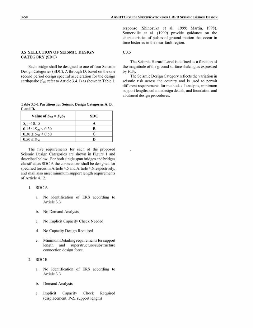
3-50 AASHTO GUIDE SPECIFICATION FOR LRFD SEISMIC BRIDGE DESIGN
response (Shinozuka et al., 1999; Martin, 1998). Somerville et al. (1999) provide guidance on the characteristics of pulses of ground motion that occur in time histories in the near-fault region.
3.5 SELECTION OF SEISMIC DESIGN CATEGORY (SDC)
Each bridge shall be designed to one of four Seismic
Design Categories (SDC), A through D, based on the onesecond period design spectral acceleration for the designearthquake (SD1 refer to Article 3.4.1) as shown in Table 1.
C3.5 The Seismic Hazard Level is defined as a function of
the magnitude of the ground surface shaking as expressed by FvS1.
The Seismic Design Category reflects the variation in seismic risk across the country and is used to permit different requirements for methods of analysis, minimum support lengths, column design details, and foundation and abutment design procedures.
Table 3.5-1 Partitions for Seismic Design Categories A, B, C and D.
Value of SD1 = FvS1 SDC
SD1 < 0.15 A 0.15 ≤ SD1 < 0.30 B 0.30 ≤ SD1 < 0.50 C 0.50 ≤ SD1 D
The five requirements for each of the proposed
Seismic Design Categories are shown in Figure 1 anddescribed below. For both single span bridges and bridgesclassified as SDC A the connections shall be designed forspecified forces in Article 4.5 and Article 4.6 respectively,and shall also meet minimum support length requirements of Article 4.12.
1. SDC A
a. No identification of ERS according to
Article 3.3
b. No Demand Analysis
c. No Implicit Capacity Check Needed
d. No Capacity Design Required
e. Minimum Detailing requirements for supportlength and superstructure/substructureconnection design force
2. SDC B
a. No Identification of ERS according to
Article 3.3
b. Demand Analysis
c. Implicit Capacity Check Required (displacement, P-Δ, support length)
.

SECTION 3: GENERAL REQUIREMENTS 3-51
d. No Capacity Design Required except forcolumn shear requirement
e. SDC B Level of Detailing
3. SDC C
a. Identification of ERS
b. Demand Analysis
c. Implicit Capacity Check Required
(displacement, P-Δ, support length)
d. Capacity Design Required includingcolumn shear requirement
e. SDC C Level of Detailing
4. SDC D
a. Identification of ERS
b. Demand Analysis
c. Displacement Capacity Required using
Pushover Analysis (check P-Δ and support length)
d. Capacity Design Required including column
shear requirement
e. SDC D Level of Detailing
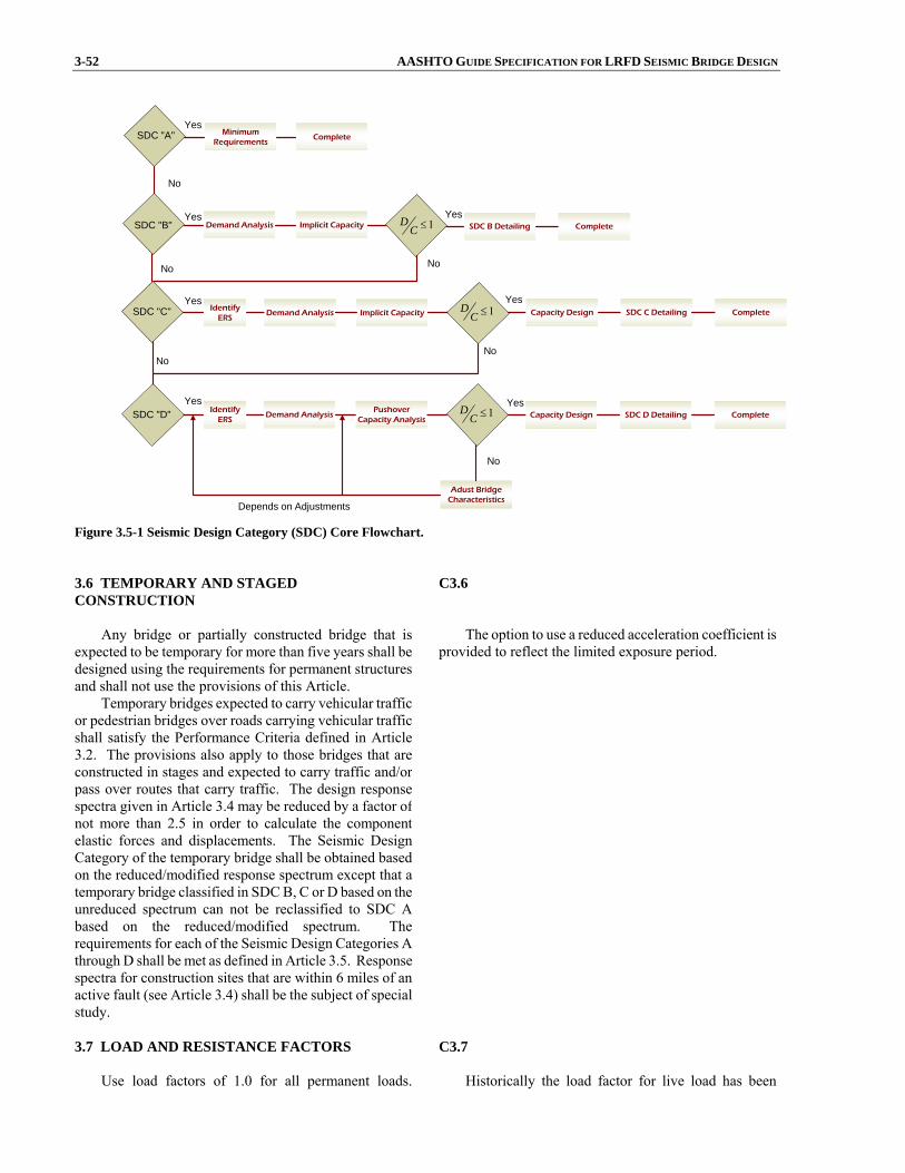
3-52 AASHTO GUIDE SPECIFICATION FOR LRFD SEISMIC BRIDGE DESIGN
SDC "A"
SDC "B"
Implicit Capacity
MinimumRequirements
Demand Analysis Implicit Capacity
Yes
No
Yes1D
C ≤ SDC B Detailing CompleteYes
SDC "C"
No No
YesDemand Analysis 1D
C ≤ Capacity Design SDC C Detailing
YesComplete
SDC "D"
NoNo
Demand AnalysisPushover
Capacity Analysis1D
C ≤ Capacity Design SDC D DetailingYes
Complete
No
Adust BridgeCharacteristics
Depends on Adjustments
Yes
IdentifyERS
IdentifyERS
Complete
Figure 3.5-1 Seismic Design Category (SDC) Core Flowchart. 3.6 TEMPORARY AND STAGED CONSTRUCTION
Any bridge or partially constructed bridge that is
expected to be temporary for more than five years shall bedesigned using the requirements for permanent structuresand shall not use the provisions of this Article.
Temporary bridges expected to carry vehicular trafficor pedestrian bridges over roads carrying vehicular traffic shall satisfy the Performance Criteria defined in Article3.2. The provisions also apply to those bridges that areconstructed in stages and expected to carry traffic and/orpass over routes that carry traffic. The design responsespectra given in Article 3.4 may be reduced by a factor ofnot more than 2.5 in order to calculate the componentelastic forces and displacements. The Seismic DesignCategory of the temporary bridge shall be obtained basedon the reduced/modified response spectrum except that a temporary bridge classified in SDC B, C or D based on theunreduced spectrum can not be reclassified to SDC Abased on the reduced/modified spectrum. Therequirements for each of the Seismic Design Categories Athrough D shall be met as defined in Article 3.5. Responsespectra for construction sites that are within 6 miles of anactive fault (see Article 3.4) shall be the subject of specialstudy.
C3.6 The option to use a reduced acceleration coefficient is
provided to reflect the limited exposure period.
3.7 LOAD AND RESISTANCE FACTORS
Use load factors of 1.0 for all permanent loads.
C3.7 Historically the load factor for live load has been

SECTION 3: GENERAL REQUIREMENTS 3-53 Unless otherwise noted, all φ factors shall be taken as 1.0 taken as zero for the earthquake load combination except
where heavy truck traffic, high ADT or long structure length are anticipated.


SECTION 4: ANALYSIS AND DESIGN REQUIREMENTS
TABLE OF CONTENTS
4-i
4.1 GENERAL........................................................................................................................................................ 4-1
4.1.1 Balanced Stiffness SDC D ...................................................................................................................... 4-1 4.1.2 Balanced Frame Geometry SDC D ......................................................................................................... 4-4 4.1.3 Adjusting Dynamic Characteristics......................................................................................................... 4-4 4.1.4 End Span Considerations ........................................................................................................................ 4-5
4.2 SELECTION OF ANALYSIS PROCEDURE TO DETERMINE SEISMIC DEMAND................................. 4-5 4.2.1 Special Requirements for Curved Bridges .............................................................................................. 4-6 4.2.2 Limitations and Special Requirements.................................................................................................... 4-6
4.3 DETERMINATION OF SEISMIC LATERAL DIPSLACMENT DEMANDS............................................... 4-7 4.3.1 Horizontal Ground Motions .................................................................................................................... 4-7 4.3.2 Displacement Modification for Other Than 5% Damped Bridges .......................................................... 4-7 4.3.3 Displacement Magnification for Short Period Structures........................................................................ 4-8
4.4 COMBINATION OF ORTHOGONAL SEISMIC DISPLACEMENT DEMANDS ....................................... 4-9 4.5 DESIGN REQUIREMENTS FOR SINGLE SPAN BRIDGES........................................................................ 4-10 4.6 DESIGN REQUIREMENTS FOR SEISMIC DESIGN CATEGORY A ......................................................... 4-10 4.7 DESIGN REQUIREMENTS FOR SEISMIC DESIGN CATEGORIES B, C, AND D ................................... 4-11 4.7.1 Design Methods for Lateral Seismic Displacement Demands ................................................................. 4-11 4.7.2 Vertical Ground Motion, Design Requirements for SDC D ................................................................... 4-12 4.8 STRUCTURE DISPLACEMENT DEMAND/CAPACITY FOR SDC B, C, AND D..................................... 4-12
4.8.1 Local Displacement Capacity for SDC B and C ..................................................................................... 4-13 4.8.2 Local Displacement Capacity for SDC D ............................................................................................... 4-14
4.9 MEMBER DUCTILITY REQUIREMENT FOR SDC D................................................................................. 4-14 4.10 COLUMN SHEAR REQUIREMENTS FOR SDC B, C, AND D.................................................................. 4-15 4.11 CAPACITY DESIGN REQUIREMENT FOR SDC C AND D ..................................................................... 4-15
4.11.1 Capacity Design.................................................................................................................................... 4-15 4.11.2 Plastic Hinging Forces .......................................................................................................................... 4-15 4.11.3 Single Columns and Piers ..................................................................................................................... 4-18 4.11.4 Bents With Two or More Columns....................................................................................................... 4-18 4.11.5 P-Δ Capacity Requirement for SDC C and D ....................................................................................... 4-19 4.11.6 Analytical Plastic Hinge Length ........................................................................................................... 4-21 4.11.7 Reinforced Concrete Column Plastic Hinge Region ............................................................................. 4-22 4.11.8 Steel Column Plastic Hinge Region ...................................................................................................... 4-22
4.12 MINIMUM SUPPORT LENGTH REQUIREMENTS................................................................................... 4-22 4.12.1 Seismic Design Categories A, B, and C................................................................................................ 4-22 4.12.2 Seismic Design Category D .................................................................................................................. 4-23 4.13 SUPPORT RESTRAINTS FOR SDC C AND D............................................................................................ 4-24
4.13.1 Longitudinal Restrainers ....................................................................................................................... 4-24 4.13.2 Simple Span Superstructures................................................................................................................. 4-24 4.13.3 Detailing Restrainers............................................................................................................................. 4-25
4.14 SUPERSTRUCTURE SHEAR KEYS............................................................................................................ 4-25

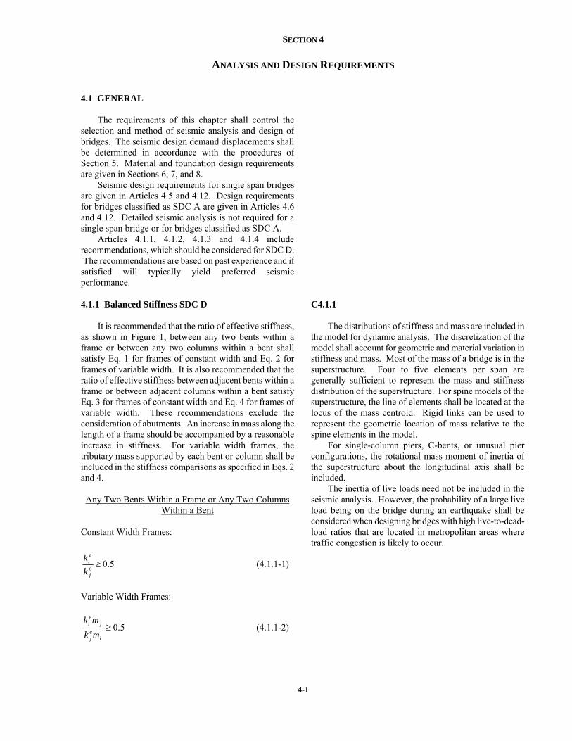
SECTION 4
ANALYSIS AND DESIGN REQUIREMENTS
4-1
4.1 GENERAL
The requirements of this chapter shall control the
selection and method of seismic analysis and design of bridges. The seismic design demand displacements shallbe determined in accordance with the procedures of Section 5. Material and foundation design requirements are given in Sections 6, 7, and 8.
Seismic design requirements for single span bridgesare given in Articles 4.5 and 4.12. Design requirementsfor bridges classified as SDC A are given in Articles 4.6 and 4.12. Detailed seismic analysis is not required for asingle span bridge or for bridges classified as SDC A.
Articles 4.1.1, 4.1.2, 4.1.3 and 4.1.4 includerecommendations, which should be considered for SDC D. The recommendations are based on past experience and if satisfied will typically yield preferred seismicperformance.
4.1.1 Balanced Stiffness SDC D
It is recommended that the ratio of effective stiffness, as shown in Figure 1, between any two bents within aframe or between any two columns within a bent shall satisfy Eq. 1 for frames of constant width and Eq. 2 for frames of variable width. It is also recommended that theratio of effective stiffness between adjacent bents within aframe or between adjacent columns within a bent satisfy Eq. 3 for frames of constant width and Eq. 4 for frames of variable width. These recommendations exclude theconsideration of abutments. An increase in mass along thelength of a frame should be accompanied by a reasonableincrease in stiffness. For variable width frames, thetributary mass supported by each bent or column shall beincluded in the stiffness comparisons as specified in Eqs. 2and 4.
Any Two Bents Within a Frame or Any Two Columns Within a Bent
Constant Width Frames:
5.0≥ej
ei
kk (4.1.1-1)
Variable Width Frames:
5.0≥i
ej
jei
mkmk
(4.1.1-2)
C4.1.1
The distributions of stiffness and mass are included in the model for dynamic analysis. The discretization of the model shall account for geometric and material variation in stiffness and mass. Most of the mass of a bridge is in the superstructure. Four to five elements per span are generally sufficient to represent the mass and stiffness distribution of the superstructure. For spine models of the superstructure, the line of elements shall be located at the locus of the mass centroid. Rigid links can be used to represent the geometric location of mass relative to the spine elements in the model.
For single-column piers, C-bents, or unusual pierconfigurations, the rotational mass moment of inertia of the superstructure about the longitudinal axis shall be included.
The inertia of live loads need not be included in the seismic analysis. However, the probability of a large live load being on the bridge during an earthquake shall be considered when designing bridges with high live-to-dead-load ratios that are located in metropolitan areas where traffic congestion is likely to occur.

4-2 AASHTO GUIDE SPECIFICATIONS FOR LRFD SEISMIC BRIDGE DESIGN
Adjacent Bents Within a Frame or Adjacent Columns Within a Bent
Constant Width Frames:
75.0≥ej
ei
kk (4.1.1-3)
Variable Width Frames:
75.0≥i
ej
jei
mkmk (4.1.1-4)
where:
eik = smaller effective bent or column stiffness
(kip/in.)
ejk = larger effective bent or column stiffness (kip/in.)
mi = tributary mass of column or bent i (kip) mj = tributary mass of column or bent j (kip)
The following considerations shall be taken intoaccount when calculating effective stiffness of concretecomponents: framing effects, end conditions, columnheight, percentage of longitudinal and transverse columnsteel, column diameter, and foundation flexibility. Someof the consequences of not meeting the relative stiffnessrecommendations defined above include:
• Increased damage in the stiffer elements
• An unbalanced distribution of inelastic response throughout the structure
• Increased column torsion generated by rigid bodyrotation of the superstructure
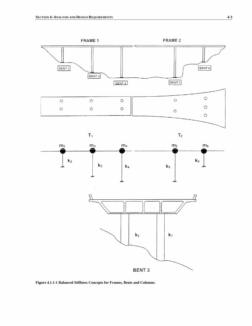
SECTION 4: ANALYSIS AND DESIGN REQUIREMENTS 4-3
Figure 4.1.1-1 Balanced Stiffness Concepts for Frames, Bents and Columns.
4-4 AASHTO GUIDE SPECIFICATIONS FOR LRFD SEISMIC BRIDGE DESIGN 4.1.2 Balanced Frame Geometry SDC D
It is recommended that the ratio of fundamentalperiods of vibration for adjacent frames in the longitudinal and transverse direction satisfy:
7.0≥j
i
TT (4.1.2-1)
where: Ti = natural period of the less flexible frame (sec.) Tj = natural period of the more flexible frame (sec.)
The consequences of not meeting the fundamental period requirements of Eq. 1 include a greater likelihood of out-of-phase response between adjacent frames leadingto large relative displacements between the frames thatincrease the probability of longitudinal unseating andpounding between frames at the expansion joints. Thepounding and relative transverse translation of adjacentframes will transfer the seismic demand from one frame tothe next, which can be detrimental to the stand-alone capacity of the frame receiving the additional seismicdemand.
C4.1.2
For bridges with multiple frames, which are separated by expansion bearings or hinges, it is unnecessary to model and analyze the entire bridge for seismic loads. Each frame shall have sufficient strength to resist inertia loads from the mass of the frame. However, when adjacent frames have large differences in vibration period, the frame with the longer period may increase the seismic load on the frame with the shorter period by impact across the bearing or hinge, or by transverse forces through shear keys. To account for these effects, the number of frames included in a model depends on the ratio of vibration period of the frames. For bridges in which the period ratio of adjacent frames is less than 0.70 (shortest period frame divided by longest period frame), it is recommended to limit a model to five frames. The first and fifth frames in the model are considered to be boundary frames, representing the interaction with the remainder of the structure. The response of the three interior frames can be used for design of those frames. For a bridge with more than five frames, several different models are then used in the design. For bridges with period ratios of frames between 0.70 and 1.0, fewer than five frames may be used in a model.
4.1.3 Adjusting Dynamic Characteristics
The following list of techniques should be considered for adjusting or tuning the fundamental period of vibrationand/or stiffness to satisfy Eqs. 4.1.1-1 to 4.1.1-4 and 4.1.2-1.
• Use of oversized pile shafts
• Adjust effective column lengths (i.e. lowerfootings, isolation casing)
• Use of modified end fixities
• Reduce and/or redistribute superstructure mass
• Vary the column cross section and longitudinal
reinforcement ratios
• Add or relocate columns
• Modify the hinge/expansion joint layout
• Incorporate isolation bearings or dampers (i.e.,response modification devices)
• Rearticulation
A careful evaluation of the local ductility demands
and capacities is required for SDC D, if project constraints

SECTION 4: ANALYSIS AND DESIGN REQUIREMENTS 4-5 make it impractical to satisfy the stiffness and structureperiod requirements in Eqs. 4.1.1-1 to 4.1.1-4, and 4.1.2-1.
4.1.4 End Span Considerations
The influence of the superstructure rigidity on thetransverse stiffness of single column bents near theabutment shall be considered. This is particularly important when calculating shear demands for singlecolumns where considering single curvature of the columnis deemed non-conservative for ensuring adequate shearcapacity.
4.2 SELECTION OF ANALYSIS PROCEDURE TO DETERMINE SEISMIC DEMAND
Minimum requirements for the selection of an analysis
method to determine seismic demands for a particularbridge type are given in Tables 1 and 2. Applicability isdetermined by the “regularity” of a bridge which is afunction of the number of spans and the distribution of weight and stiffness. Regular bridges are defined as thosehaving less than seven spans, no abrupt or unusual changesin weight, stiffness, or geometry. The changes in theseparameters for SDC D should be within the tolerancesgiven by Equations 4.1.1-1 to 4.1.1-4 from span-to-span or from support-to-support (abutments excluded). Regularbridge requirements are defined in Table 3. Any bridge not satisfying the requirements of Table 3 shall be considered “not regular”. Table 4.2-1 Analysis Procedures.
Seismic Design
Category
Regular Bridges with 2 through 6
Spans
Not Regular Bridges with 2 or more Spans
A Not required Not required
B, C, or D Use Procedure 1 or 2 Use Procedure 2
Details of the Analytical model and Procedures
mentioned in Table 1 are provided in Section 5.
The analysis procedures to be used are as follows: Table 4.2-2 Description of Analysis Procedures.
Procedure Number
Description Article
1 Equivalent Static 5.4.2
2 Elastic Dynamic Analysis 5.4.3
3 Non-linear Time History 5.4.4
Procedure 3 is generally not required unless requested
by the Owner under Article 4.2.2.

4-6 AASHTO GUIDE SPECIFICATIONS FOR LRFD SEISMIC BRIDGE DESIGN Table 4.2-3 Regular Bridge Requirements.
Parameter Value Number of Spans 2 3 4 5 6
Maximum subtended angle (curved bridge)
90º 90º 90º 90º 90º
Maximum span length ratio from span-to-span
3 2 2 1.5 1.5
Maximum bent/pier stiffness ratio from span-to-span (excluding abutments)
- 4 4 3 2
Note: All ratios expressed in terms of the smaller value.
4.2.1 Special Requirements for Curved Bridges
A curved bridge may be analyzed as if it were straight provided all of the following requirements are satisfied:
a. the bridge is regular as defined in Table 4.2-3except that for a two-span bridge the maximumspan length ratio from span-to-span shall notexceed 2;
b. the subtended angle in plan is not greater than
90°, and
c. the span lengths of the equivalent straight bridgeare equal to the arc lengths of the curved bridge.
If these requirements are not satisfied, then curved
bridges shall be analyzed using the actual curvedgeometry.
C4.2.1
A common practice is to define the “longitudinal direction” of a curved bridge as that of the chord connecting the ends of the bridge, and the transverse direction as orthogonal to the longitudinal direction.
4.2.2 Limitations and Special Requirements
More rigorous methods of analysis are required forcertain classes of important bridges which are consideredto be critical or essential structures, and/or for those thatare geometrically complex or close to active earthquakefaults (see Article 3.4.3). Critical and Essential Bridgesare not specifically addressed in this specification.Procedure 3, Non-linear Time History Analyses aregenerally recommended for critical and essential bridges asapproved by the owner. There are however, some cases,where seismic isolation is used for Normal Bridges, whichrequires the use of nonlinear time history analysis.Nonlinear time history methods of analysis are describedin Section 5 of the specifications.
For a bridge to be classified as an Essential Bridge ora Critical Bridge, one or more of the following items arerequired to be present: (1) bridge is required to providesecondary life safety, (2) sufficient time for restoration offunctionality after closure creates a major economicimpact, and (3) the bridge is formally designated as criticalfor a defined local emergency plan.
C4.2.2
Essential or Critical Bridges within 6 miles of an active fault require a site-specific study and inclusion of vertical ground motion in the seismic analysis. For normal bridges located within 6 miles from an active fault, the procedures in Article 4.7.2 are used to account for the response to vertical ground motion in lieu of including the vertical component in the seismic analysis. For bridges with long, flexible spans, C-bents, or other large eccentricity in the load path for vertical loads, it is recommended to include vertical ground motion in the dynamic analysis.
SECTION 4: ANALYSIS AND DESIGN REQUIREMENTS 4-7
A bridge is classified as Critical, Essential or Normalas follows:
Critical Bridges: Bridges that are required to be opento all traffic once inspected after the design earthquake andbe usable by emergency vehicles and for security/defensepurposes immediately after the design earthquake.
Essential Bridges: Bridges that should, as a minimum,be open to emergency vehicles and for security/defensepurposes after the design earthquake and open to all traffic within days after that event.
Normal Bridges: Any bridge not classified as aCritical or Essential Bridge. 4.3 DETERMINATION OF SEISMIC LATERALDISPLACEMENT DEMANDS
The global structure displacement demand, ΔD, is the
total seismic displacement at a particular location within the structure or subsystem. The global displacementdemand will include components attributed to foundationflexibility, Δf (i.e. foundation rotation or translation),flexibility of essentially elastic components such as bentcaps Δb, and the flexibility attributed to elastic andinelastic response of ductile members Δy and Δpd,respectively.
Minimum requirements for superstructure, abutment, and foundation modeling are specified in Section 5.
4.3.1 Horizontal Ground Motions
For bridges classified as SDC B, C or D the globalseismic displacement demands, ΔD, shall be determinedindependently along two perpendicular axes by the use of the analysis procedure specified in Article 4.2 and asmodified using Article 4.3.2 and 4.3.3. The resulting displacements shall then be combined as specified inArticle 4.4. Typically, the perpendicular axes are thelongitudinal and transverse axes of the bridge. Thelongitudinal axis of a curved bridge may be selected alonga chord connecting the two abutments.
4.3.2 Displacement Modification for Other Than 5%Damped Bridges
Damping ratios on the order of 10% can be used withthe approval of the owner for bridges that are substantiallyinfluenced by energy dissipation of the soils at theabutments and are expected to respond predominately as a single-degree-of-freedom system. A reduction factor, RD, can be applied to the 5% damped design spectrum coefficient used to calculate the displacement demand.
The following characteristics are typically goodindicators that higher damping is justified.
• Total bridge length is less than 300 ft.
• Abutments are designed for sustained soilmobilization.
C4.3.2
Damping may be neglected in the calculation of natural frequencies and associated modal displacements. The effects of damping shall be considered when the dynamic response for seismic loads is considered. The specified ground motion spectra are for 5% viscous damping and this is a reasonably conservative value.
Suitable damping values may be obtained from field measurement of induced free vibration or by forced vibration tests. In lieu of measurements, the following values may be used for the equivalent viscous damping ratio of time-history analysis:
• Concrete construction: 5%
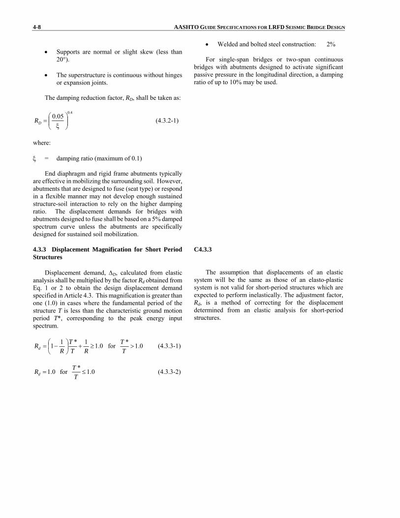
4-8 AASHTO GUIDE SPECIFICATIONS FOR LRFD SEISMIC BRIDGE DESIGN
• Supports are normal or slight skew (less than20°).
• The superstructure is continuous without hinges
or expansion joints.
The damping reduction factor, RD, shall be taken as:
4.005.0
⎟⎟⎠
⎞⎜⎜⎝
⎛ξ
=DR (4.3.2-1)
where: ξ = damping ratio (maximum of 0.1)
End diaphragm and rigid frame abutments typicallyare effective in mobilizing the surrounding soil. However,abutments that are designed to fuse (seat type) or respondin a flexible manner may not develop enough sustainedstructure-soil interaction to rely on the higher dampingratio. The displacement demands for bridges withabutments designed to fuse shall be based on a 5% dampedspectrum curve unless the abutments are specificallydesigned for sustained soil mobilization.
• Welded and bolted steel construction: 2%
For single-span bridges or two-span continuous bridges with abutments designed to activate significant passive pressure in the longitudinal direction, a damping ratio of up to 10% may be used.
4.3.3 Displacement Magnification for Short PeriodStructures
Displacement demand, ΔD, calculated from elasticanalysis shall be multiplied by the factor Rd obtained fromEq. 1 or 2 to obtain the design displacement demand specified in Article 4.3. This magnification is greater thanone (1.0) in cases where the fundamental period of thestructure T is less than the characteristic ground motionperiod T*, corresponding to the peak energy inputspectrum.
C4.3.3
The assumption that displacements of an elastic system will be the same as those of an elasto-plastic system is not valid for short-period structures which are expected to perform inelastically. The adjustment factor, Rd, is a method of correcting for the displacement determined from an elastic analysis for short-period structures.
0.11*11 ≥+⎟⎠⎞
⎜⎝⎛ −=
RTT
RRd for 0.1*
>T
T (4.3.3-1)
0.1=dR for 0.1*≤
TT (4.3.3-2)

SECTION 4: ANALYSIS AND DESIGN REQUIREMENTS 4-9 in which: T* = 1.25Ts (4.3.3-3) R = maximum expected displacement ductility of the structure = 2 for SDC B = 3 for SDC C = μD for SCD D where: Ts = period determined from Article 3.4.1 (sec.) μD = maximum local member displacement ductility demand determined in accordance with Article
4.9. In lieu of a detailed analysis, μD may be taken as 6.
The displacement magnification is applied separately
in both orthogonal directions prior to obtaining theorthogonal combination of seismic displacements specifiedin Article 4.4.
4.4 COMBINATION OF ORTHOGONAL SEISMIC DISPLACEMENT DEMANDS
C4.4
A combination of orthogonal seismic displacement
demands is used to account for the directional uncertaintyof earthquake motions and the simultaneous occurrences ofearthquake forces in two perpendicular horizontaldirections. The seismic displacements resulting fromanalyses in the two perpendicular directions as describedin Article 4.3 shall be combined to form two independentload cases as follows:
LOAD CASE 1: Seismic demand displacements alongeach of the principal axes of a member shall beobtained by adding 100% of the absolute value of the member seismic displacements resulting from theanalysis in one of the perpendicular (longitudinal) directions to 30% of the absolute value of thecorresponding member seismic displacements resulting from the analysis in the secondperpendicular direction (transverse).
LOAD CASE 2: Seismic displacements on each of theprincipal axes of a member shall be obtained byadding 100% of the absolute value of the memberseismic displacements resulting from the analysis inthe second perpendicular direction (transverse) to 30%of the absolute value of the corresponding member seismic displacements resulting from the analysis inthe first perpendicular direction (longitudinal). There are some design procedures that require the
development of elastic seismic forces. The procedure for
The combination of seismic displacements computed from a response spectrum analysis has two aspects.
The first is the combination of the vibration modes due to ground motion in one direction (longitudinal, transverse, or vertical). The CQC method (“complete quadratic combination") provides a good estimate of the maximum displacement, including the correlation of modal responses closely spaced in frequency.
The second is the contribution of two or three orthogonal ground motion components to a single force effect. The SRSS rule ("square root sum of the squares") is the most appropriate rule for combining the contribution of orthogonal, and uncorrelated, ground motion components to a single seismic displacement. The SRSS method is recommended particularly for seismic analysis including vertical ground motion (Button et. al. 1999). However, AASHTO seismic provisions that are based on a 100% - 30% combination are permitted and adequate for the scope of the structure types for which these Guide Specifications are intended.

4-10 AASHTO GUIDE SPECIFICATIONS FOR LRFD SEISMIC BRIDGE DESIGN developing such forces is the same as that fordisplacements.
4.5 DESIGN REQUIREMENTS FOR SINGLE SPANBRIDGES
C4.5
A detailed seismic analysis is not required for single
span bridges regardless of SDC as specified in Article 4.1. However, the connections between the bridge span andthe abutments shall be designed both longitudinally andtransversely to resist a horizontal seismic force not lessthan the product of the effective peak ground acceleration coefficient, 0.4SDS, as specified in Article 3.4, times thetributary permanent load except as modified for SDC A inArticle 4.6. The lateral force shall be carried into thefoundation in accordance with Articles 5.2 and 6.7. Theminimum support lengths shall be as specified in Article4.12.
Requirements for single-span bridges are not as rigorous as for multi-span bridges because of their favorable response to seismic loads in past earthquakes. As a result, single-span bridges need not be analyzed for seismic loads regardless of the SDC, and design requirements are limited to minimum support lengths and connection forces. Adequate support lengths shall be provided in both the transverse and longitudinal directions. Connection forces are based on the premise that the bridge is very stiff and that the fundamental period of response will be short. This assumption acknowledges the fact that the period of vibration is difficult to calculate because of significant interaction with the abutments.
These reduced requirements are also based on the assumption that there are no vulnerable substructures (i.e., no columns) and that a rigid (or near-rigid) superstructure is in place to distribute the in-plane loads to the abutments. If, however, the superstructure is not able to act as a stiff diaphragm and sustains significant in-plane deformation during horizontal loading, it should be analyzed for these loads and designed accordingly.
Single-span trusses may be sensitive to in-plane loads and the designer may need to take additional precautions to ensure the safety of truss superstructures.
4.6 DESIGN REQUIREMENTS FOR SEISMIC DESIGN CATEGORY A
C4.6
For bridges in SDC A, where the effective peak
ground acceleration coefficient, 0.4SDS, as specified in Article 3.4., is less than 0.05, the horizontal designconnection force in the restrained directions shall not beless than 0.15 times the vertical reaction due to thetributary permanent load.
For all other sites in SDC A, the horizontal designconnection force in the restrained directions shall not beless than 0.25 times the vertical reaction due to thetributary permanent load and the tributary live loadsassumed to exist during an earthquake.
For each uninterrupted segment of a superstructure,the tributary permanent load at the line of fixed bearings,used to determine the longitudinal connection design force,shall be the total permanent load of the segment.
If each bearing supporting an uninterrupted segmentor simply supported span is restrained in the transversedirection, the tributary permanent load used to determinethe connection design force shall be the permanent loadreaction at that bearing.
Each elastomeric bearing and its connection to themasonry and sole plates shall be designed to resist thehorizontal seismic design forces transmitted through thebearing. For all bridges in SDC A and all single-span
These provisions arise because, as specified in Articles 4.1 and 4.2, seismic analysis for bridges in SDC A is not generally required. These default values are used as minimum design forces in lieu of rigorous analysis. The division of SDC A at an effective peak ground spectral acceleration coefficient of 0.05 recognizes that, in parts of the country with very low seismicity, seismic forces on connections are very small.
If each bearing supporting a continuous segment or simply supported span is an elastomeric bearing, there are no restrained directions due to the flexibility of the bearings.
The magnitude of live load assumed to exist at the time of the earthquake should be consistent with the value of γEQ used in conjunction with Table 3.4.1-1 of the AASHTO LRFD Bridge Design Specifications.
SECTION 4: ANALYSIS AND DESIGN REQUIREMENTS 4-11 bridges, these seismic shear forces shall not be less thanthe connection force specified herein.
The minimum support length for bridges in SDC A is specified in Article 4.12.
4.7 DESIGN REQUIREMENTS FOR SEISMIC DESIGN CATEGORIES B, C, AND D
4.7.1 Design Methods for Lateral Seismic Displacement Demands
For design purposes, each structure shall becategorized according to its intended structural seismicresponse in terms of damage level (i.e., ductility demand, μD, as defined by Eq. 4.9-5). The following designmethods are further defined as follows:
(a) Conventional Ductile Response (i.e. Full-Ductility Structures)
For horizontal loading, a plastic mechanism is intended to develop. The plastic mechanism shall be defined clearly as part of the design strategy.Yielding may occur in areas that are not readilyaccessible for inspection (i.e., with owner’sapproval). Inelastic action is intended to berestricted to flexural plastic hinges in columnsand pier walls and inelastic soil deformation behind abutment walls and wing walls. Detailsand member proportions shall ensure largeductility capacity, μC, under load reversalswithout significant strength loss with ductilitydemands (4.0 ≤ μD ≤ 6.0, see Article 4.9). Thisresponse is anticipated for a bridge in SDC Ddesigned for the Life Safety Criteria.
(b) Limited-Ductility Response
For horizontal loading, a plastic mechanism as described above for Full-Ductility Structures isintended to develop, but in this case for LimitedDuctility Response ductility demands are reduced(μD ≤ 4.0). Intended yielding shall be restricted to locations that are readily accessible forinspection following a design earthquake unlessprohibited by the structural configuration.Inelastic action is intended to be restricted to flexural plastic hinges in columns and pier walls,and inelastic soil deformation behind abutment walls and wingwalls. Detailing andproportioning requirements are less than thoserequired for Full-Ductility Structures. Thisresponse is anticipated for a bridge in SDC B orC.
(c) Limited-Ductility Response in Concert with
Added Protective Systems
In this case a structure has limited ductility with
C4.7.1
A key element in the design procedure is the flexural capacity of the columns. Philosophically, the lower the flexural capacity of the column the more economic will be the seismic design because the overstrength flexural capacity of a column drives the cost and capacity of both the foundations and connections to the superstructure. For SDC B the capacity of the column designed for non-seismic loads is considered to be acceptable for this lower seismic hazard level.
For SDC C and D, the design procedure provides a trade-off between acceptable design displacements and minimum flexural capacities of columns, which could in turn be governed by P-Δ effects.
4-12 AASHTO GUIDE SPECIFICATIONS FOR LRFD SEISMIC BRIDGE DESIGN
the additional seismic isolation, passive energydissipating devices, and/or other mechanicaldevices to control seismic response. Using thisstrategy, a plastic mechanism may or may notform. The occurrence of a plastic mechanismshall be verified by analysis. This response maybe used for a bridge in SDC C or D designed foran enhanced performance. Non-linear TimeHistory analysis (i.e., Procedure 3) may berequired for this design strategy.
4.7.2 Vertical Ground Motion, Design Requirementsfor SDC D
The effects of vertical ground motions for bridges inSeismic Design Category D located within six (6) miles ofan active fault as described in Article C3.4, shall beconsidered.
C4.7.2
The most comprehensive study (Button et al., 1999) performed to date on the impact of vertical acceleration effects indicates that for some design parameters (superstructure moment and shear, and column axial forces) and for some bridge types, the impact can be significant. The study was based on vertical response spectra developed by Silva (1997) from recorded western United State ground motions.
Specific recommendations for assessing vertical acceleration effects will not be provided in these Guide Specifications until more information is known about the characteristics of vertical ground motion in the central and eastern United States, and those areas impacted by subduction zones in the Pacific. However, it is advisable for designers to be aware that vertical acceleration effects may be important and should be assessed for essential and critical bridges. See Caltrans Seismic Design Criteria (Caltrans 2006).
4.8 STRUCTURE DISPLACEMENT DEMAND/ CAPACITY FOR SDC B, C, AND D
C4.8
For SDC B, C and D, each bridge bent shall satisfy:
LC
LD Δ<Δ (4.8-1)
where:
LDΔ = displacement demand taken along the local
principal axis of the ductile member as determined in accordance with Article 4.4 (in.)
LCΔ = displacement capacity taken along the local
principal axis corresponding to LDΔ of the ductile
member as determined in accordance with Article 4.8.1 for SDC B and C and in accordance with Article 4.8.2 for SDC D (in.)
Eq. 1 shall be satisfied in each of the local axis ofevery bent. The local axis of a bent typically coincideswith the principal axis of the columns in that bent.
The formulas presented below are used to obtain LCΔ
for SDC B and C. These formulas are not intended for use
The objective of the displacement capacity verification analysis is to determine the displacement at which the earthquake-resisting elements achieve their inelastic deformation capacity. Damage states are defined by local deformation limits, such as plastic hinge rotation, footing settlement or uplift, or abutment displacement. Displacement may be limited by loss of capacity from either degradation of strength under large inelastic deformations or P-Δ effects.
For simple piers or bents, the maximum displacement capacity can be evaluated by hand calculations using the defined mechanism and the maximum allowable deformations of the plastic hinges. If interaction between axial force and moment is significant, iteration is necessary to determine the mechanism.
For more complicated piers or foundations, displacement capacity can be evaluated using a nonlinear static analysis procedure (pushover analysis).
Displacement capacity verification is required for individual piers or bents. Although it is recognized that force redistribution may occur as the displacement increases, particularly for frames with piers of different
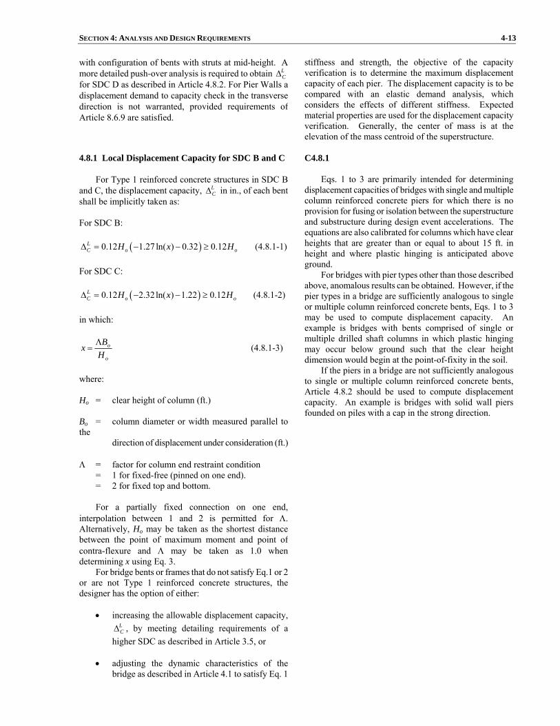
SECTION 4: ANALYSIS AND DESIGN REQUIREMENTS 4-13 with configuration of bents with struts at mid-height. A more detailed push-over analysis is required to obtain L
CΔfor SDC D as described in Article 4.8.2. For Pier Walls adisplacement demand to capacity check in the transversedirection is not warranted, provided requirements of Article 8.6.9 are satisfied.
stiffness and strength, the objective of the capacity verification is to determine the maximum displacement capacity of each pier. The displacement capacity is to be compared with an elastic demand analysis, which considers the effects of different stiffness. Expected material properties are used for the displacement capacity verification. Generally, the center of mass is at the elevation of the mass centroid of the superstructure.
4.8.1 Local Displacement Capacity for SDC B and C
For Type 1 reinforced concrete structures in SDC Band C, the displacement capacity, L
CΔ in in., of each bent shall be implicitly taken as: For SDC B:
( )0.12 1.27 ln( ) 0.32 0.12LC o oH x HΔ = − − ≥ (4.8.1-1)
For SDC C:
( )0.12 2.32ln( ) 1.22 0.12LC o oH x HΔ = − − ≥ (4.8.1-2)
in which:
o
o
HBx Λ
= (4.8.1-3)
where: Ho = clear height of column (ft.) Bo = column diameter or width measured parallel tothe direction of displacement under consideration (ft.) Λ = factor for column end restraint condition = 1 for fixed-free (pinned on one end). = 2 for fixed top and bottom.
For a partially fixed connection on one end,interpolation between 1 and 2 is permitted for Λ.Alternatively, Ho may be taken as the shortest distancebetween the point of maximum moment and point ofcontra-flexure and Λ may be taken as 1.0 whendetermining x using Eq. 3.
For bridge bents or frames that do not satisfy Eq.1 or 2 or are not Type 1 reinforced concrete structures, the designer has the option of either:
• increasing the allowable displacement capacity, LCΔ , by meeting detailing requirements of a
higher SDC as described in Article 3.5, or
• adjusting the dynamic characteristics of thebridge as described in Article 4.1 to satisfy Eq. 1
C4.8.1
Eqs. 1 to 3 are primarily intended for determining displacement capacities of bridges with single and multiple column reinforced concrete piers for which there is no provision for fusing or isolation between the superstructure and substructure during design event accelerations. The equations are also calibrated for columns which have clear heights that are greater than or equal to about 15 ft. in height and where plastic hinging is anticipated above ground.
For bridges with pier types other than those described above, anomalous results can be obtained. However, if the pier types in a bridge are sufficiently analogous to single or multiple column reinforced concrete bents, Eqs. 1 to 3 may be used to compute displacement capacity. An example is bridges with bents comprised of single or multiple drilled shaft columns in which plastic hinging may occur below ground such that the clear height dimension would begin at the point-of-fixity in the soil.
If the piers in a bridge are not sufficiently analogous to single or multiple column reinforced concrete bents, Article 4.8.2 should be used to compute displacement capacity. An example is bridges with solid wall piersfounded on piles with a cap in the strong direction.
4-14 AASHTO GUIDE SPECIFICATIONS FOR LRFD SEISMIC BRIDGE DESIGN
or 2.
4.8.2 Local Displacement Capacity for SDC D
Inelastic Quasi-Static Pushover Analysis (IQPA),commonly referred to as “pushover” analysis, shall be usedto determine the reliable displacement capacities of astructure or frame as it reaches its limit of structural stability. Displacement Capacity determined for SDC Ccan be used in lieu of a more elaborate pushover analysis.If the displacement demand is higher than the displacementcapacity determined for SDC C, a pushover analysis iswarranted (SDC D). IQPA is an incremental linearanalysis, which captures the overall nonlinear behavior of the elements, including soil effects, by pushing themlaterally to initiate plastic action. Each increment ofloading pushes the frame laterally, through all possible stages, until the potential collapse mechanism is achieved.
Because the analytical model used in the pushover analysis accounts for the redistribution of internal actions as components respond inelastically, IQPA is expected toprovide a more realistic measure of behavior than can beobtained from elastic analysis procedures.
Where foundation and superstructure flexibility can beignored as stipulated in Article 5.3.1, the two-dimensionalplane frame “pushover” analysis of a bent or a frame canbe simplified to a column model (fixed-fixed or fixed-pinned) if it does not cause a significant loss in accuracy in estimating the displacement capacities.
The effect of seismic load path on the column axialload and associated member capacities shall be consideredin the simplified model.
C4.8.2
This design procedure is a key element in the philosophic development of these Guidelines. The pushover method of analysis has seen increasing use throughout the 1990s, especially in Caltrans’ seismic retrofit program. This analysis method provides additional information on the expected deformation demands of columns and foundations and as such provides the designer with a greater understanding of the expected performance of the bridge. The use of the pushover method of analysis is used in two ways. First, it encouraged designers to be as liberal as possible with assessing ductility capacity. Second, it provides a mechanism to allow ERE’s that need the owner’s approval (Article 3.3). The trade-off was the need for a more sophisticated analysis in order that the expected deformations in critical elements could be assessed. Provided the appropriate limits (i.e., plastic rotations for in-ground hinges) are met, the ERE’s requiring the owner’s approval can be used. This method applies to all the ERE’s shown in the figures of Article 3.3.
4.9 MEMBER DUCTILITY REQUIREMENT FORSDC D
C4.9
In addition to the requirements of Article 4.8, local
member ductility demand, μD, shall satisfy: For single column bents: μD ≤ 5 (4.9-1) For multiple column bents: μD ≤ 6 (4.9-2) For pier walls in the weak direction: μD ≤ 5 (4.9-3) For pier walls in the strong direction: μD ≤ 1 (4.9-4) in which:
Local member displacements such as column displacements, Δcol are defined as the portion of global displacement attributed to the elastic column idealized displacement Δyi and plastic displacement demand Δpd of an equivalent member from the point of maximum moment to the point of contra-flexure. Member section properties are obtained from a Moment-Curvature Analysis and used to calculate Δyi and the plastic displacement capacity Δpc.
SECTION 4: ANALYSIS AND DESIGN REQUIREMENTS 4-15
yi
pdD Δ
Δ+=μ 1 (4.9-5)
where: Δpd = plastic displacement demand (in.) Δyi = idealized yield displacement corresponding to the
idealized yield curvature, φyi, shown in Figure8.5-1 (in.)
Pile shafts are treated similar to columns.
4.10 COLUMN SHEAR REQUIREMENTS FOR SDCB, C, AND D
For SDC B, C, or D, shear design requirements for
reinforced concrete columns shall be satisfied according toArticle 8.6. Determination of member ductility demand isrequired for SDC D only as stipulated in Article 8.6.2.
4.11 CAPACITY DESIGN REQUIREMENT FOR SDC C AND D
4.11.1 Capacity Design
Capacity design principles require that thosecomponents not participating as part of the primary energy dissipating system (typically flexural hinging in columnsabove ground; or in some cases, flexural hinging of drilledshafts, solid wall encased pile bents, etc. below ground),shall be capacity protected. The components include the superstructure, joints and cap beams, spread footings, pilecaps and foundations. This is achieved by ensuring themaximum moment and shear from plastic hinges in the column considering overstrength can be resisted elasticallyby adjoining elements.
For SDC C or D, exception to capacity design ispermitted for the following:
a. The seismic resisting system includes the fusingeffects of an isolation device (Type 3 global design strategy).
b. A ductile end diaphragm is incorporated into the
transverse response of a steel superstructure(Type 2 global design strategy. See Article7.2.2).
c. A foundation situated in soft or potentially
liquefiable soils where plastic hinging is permitted below ground.
C4.11.1
The objective of these provisions for conventional design is that inelastic deformation (plastic hinging) occurs at the location in the columns (top or bottom or both) where they can be readily inspected and repaired. To achieve this objective, all members connected to the columns, the shear capacity of the column, and all members in the load path from the superstructure to the foundation, shall be capable of transmitting the maximum (overstrength) force effects developed by plastic hinges in the columns. The exceptions to the need for capacity design of connecting elements are: (1) when all substructure elements are designed elastically, (2) seismic isolation design, and (3) in the transverse direction of columns when a ductile diaphragm is used.
4.11.2 Plastic Hinging Forces
Plastic hinges shall form before any other failure dueto overstress or instability in the overall structure and/or in
C4.11.2
The principles of capacity design require that the strength of those members that are not part of the primary

4-16 AASHTO GUIDE SPECIFICATIONS FOR LRFD SEISMIC BRIDGE DESIGN the foundation. Except for pile bents and drilled shafts,and with owners’ approval, plastic hinges shall only bepermitted at locations in columns where they can bereadily inspected and/or repaired, as described in Article3.3.
Superstructure and substructure components and theirconnections to columns that are designed not to yield shallbe designed to resist overstrength moments and shears ofductile columns. Except for the geotechnical aspects fordesign of foundations, the moment overstrength capacity(Mpo in kip-in.) of column/pier/pile members that form partof the primary mechanism resisting seismic loads shall beassessed as given below or by using the applicableprovisions of Sections 7 and 8. For reinforced concrete members:
pmopo MM λ= (4.11.2-1) where: Mp = plastic moment capacity of column (kip-in.) λmo = overstrength factor taken as 1.2 or 1.4 as determined from Article 8.5 For steel members:
nmopo MM λ= (4.11.2-2) where: Mn = nominal moment strength for which expected steel strengths for steel members are used (kip- in.) λmo = overstrength factor taken as 1.2 as determined from Article 7.3
The plastic moment capacity, Mp, for reinforced concrete columns is determined using a moment-curvaturesection analysis; taking into account the expected yield strength of the materials, the confined concrete properties,and the strain hardening effects of the longitudinalreinforcement.
These overstrength moments and associated shearforces, calculated on the basis of inelastic hinging at overstrength, shall be taken as the extreme seismic forcesthat the bridge is capable of resisting. Typical methods ofapplying capacity design at a bent in the longitudinal andtransverse directions are shown in Figure 1 and illustratedin Article 4.11.3 for single column bents and Article 4.11.4for multi-column bents.
energy-dissipating system be stronger than the overstrength capacity of the primary energy-dissipating members, i.e. the columns with hinges at their member ends.
When assessing overstrength capacity of flexural members using compatibility section analysis (i.e., the moment-curvature method), it is important to differentiate between overstrength resulting from the response of the section to high curvature demands, and overstrength resulting from upper-bound material properties.
For example, for reinforced concrete columns, confined concrete will have enhanced capacity and reinforcing steel will strain-harden at high plastic curvatures. This will result in increased flexural capacity of the column that will be captured by a moment-curvature analysis that considers these factors. In addition, reinforcing steel can have a higher than nominal yieldpoint, and concrete is likely to be stronger than specified and will gain strength with age beyond the 28-day specified strength (ATC, 1996).
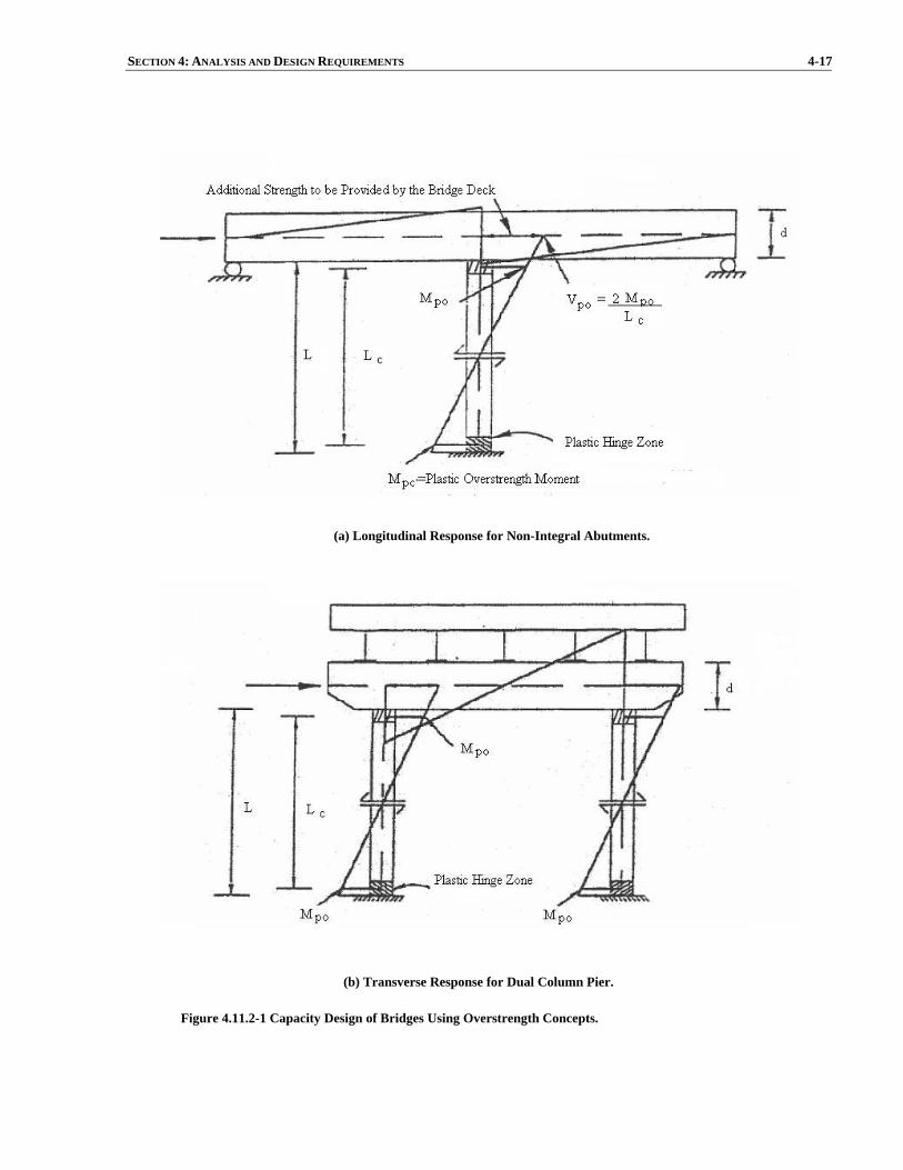
SECTION 4: ANALYSIS AND DESIGN REQUIREMENTS 4-17
(a) Longitudinal Response for Non-Integral Abutments.
(b) Transverse Response for Dual Column Pier.
Figure 4.11.2-1 Capacity Design of Bridges Using Overstrength Concepts.

4-18 AASHTO GUIDE SPECIFICATIONS FOR LRFD SEISMIC BRIDGE DESIGN 4.11.3 Single Columns and Piers
Column design shear forces and moments in thesuperstructure, bent caps, and the foundation structure shall be calculated for the two principal axes of a column and in the weak direction of a pier or bent as follows:
Step 1. Determine the column overstrength momentcapacities. Use an overstrength factor times the plasticmoment capacity or nominal moment as specified inArticle 4.11.2. The nominal moment or plasticmoment capacity members are calculated using theexpected yield strengths and subjected to the applieddead load on the section under consideration. Columnoverstrength moments should be distributed to theconnecting structural elements. (Exception: whencalculating the design forces for the geotechnicalaspects of foundations such as determining lateralstability or tip elevation, use an overstrength factor of1.0 on the nominal moment.)
Step 2. Using the column overstrength moments, calculate the corresponding column shear forceassuming a quasi-static condition. For flared columnsdesigned to be monolithic with superstructure or withisolation gaps less than required by Article 8.14, theshear shall be calculated as the greatest shear obtainedfrom using:
a. The overstrength moment at both the top of the
flare and the top of the foundation with theappropriate column height.
b. The overstrength moment at both the bottom of
the flare and the top of the foundation with thereduced column height.
Step 3. Calculate forces in the superstructure for longitudinal direction loading and forces in thefoundation for both longitudinal and transverse loading.
4.11.4 Bents With Two or More Columns
The forces for bents with two or more columns shallbe calculated both in the plane of the bent andperpendicular to the plane of the bent. Perpendicular to the plane of the bent the forces shall be calculated as for singlecolumns in Article 4.11.3. In the plane of the bent theforces shall be calculated as follows:
Step 1. Determine the column overstrength momentcapacities. Use an overstrength factor times the plasticmoment capacity or nominal moment as specified inArticle 4.11.2. The nominal moment or plasticmoment capacity for members is calculated using theexpected yield strengths and subjected to the applied
SECTION 4: ANALYSIS AND DESIGN REQUIREMENTS 4-19
dead load on the section under consideration.
Step 2. Using the column overstrength moments calculate the corresponding column shear forces. Sumthe column shears of the bent to determine the maximum shear force for the bent. If a partial-height wall exists between the columns, the effective columnheight is taken from the top of the wall. For flaredcolumns and foundations below ground level seeArticle 4.11.3 - Step 2. Step 3. Apply the bent shear force to the top of thebent (center of mass of the superstructure above the bent) and determine the axial forces in the columnsdue to overturning when the column overstrengthmoments are developed. Step 4. Using these column axial forces combined with the dead load axial forces, determine revisedcolumn overstrength moments. With the revisedoverstrength moments calculate the column shearforces and the maximum shear force for the bent. Ifthe maximum shear force for the bent is not within 10% of the value previously determined, use this maximum bent shear force and return to Step 3.
The forces in the individual columns in the plane of
a bent corresponding to column hinging, are:
Axial Forces. the maximum and minimum axial loadis the dead load plus or minus the axial loaddetermined from the final iteration of Step 3.
Moments. the column overstrength plastic moments oroverstrength nominal moment (Article 4.11.2)corresponding to the maximum compressive axialload specified above (in the previously bulleted item).
Shear Force. the shear force corresponding to the final column overstrength moments in Step 4 above.
Calculate forces in the superstructure for both
longitudinal and transverse direction loading and forces inthe foundation for both longitudinal and transverse loading. 4.11.5 P-Δ Capacity Requirement for SDC C and D
The dynamic effects of gravity loads acting throughlateral displacements shall be included in the design. Themagnitude of displacements associated with P-Δ effects can only be accurately captured with non-linear time history analysis. In lieu of such analysis, P-Δ effects can be ignored if the following is satisfied for the applicablecase. For reinforced concrete members:

4-20 AASHTO GUIDE SPECIFICATIONS FOR LRFD SEISMIC BRIDGE DESIGN
prdl MP 25.0≤Δ (4.11.5-1) For steel members:
nrdl MP 25.0≤Δ (4.11.5-2) where: Pdl = unfactored dead load acting on column (kip) Δr = relative lateral offset between the point of contra- flexure and the furthest end of the plastic hinge (in.) Mp = idealized plastic moment capacity of reinforced concrete column based upon expected material properties (kip-in.) Mn = nominal moment capacity of structural steel column based upon nominal material properties (kip-in.)
For a single pile shaft, Δr may be taken as:
SDr Δ−Δ=Δ (4.11.5-3) where: ΔD = displacement demand as determined in accordance with Article 4.3 (in.) ΔS = pile shaft displacement at the point of
maximum moment developed in-ground (in.)
For a pile cap in Site Classification E, or for caseswhere a modal analysis shows out-of-phase movement of the bottom of the column relative to the top of the column, Δr may be taken as:
FDr Δ+Δ=Δ (4.11.5-4) where: ΔD = displacement demand as determined in accordance with Article 4.3 (in.) ΔF = pile cap displacement (in.)
For bridges or frames that do not satisfy Eq. 1 or 2, the designer has the option of either:
• increasing the column plastic moment capacity Mp by adding longitudinal reinforcement; or
• adjusting the dynamic characteristics of the
bridge as discussed in Article 4.1 to satisfy Eq. 1

SECTION 4: ANALYSIS AND DESIGN REQUIREMENTS 4-21
or 2,
• using non-linear analysis to explicitly consider P-Δ effects.
4.11.6 Analytical Plastic Hinge Length
The analytical plastic hinge length for reinforcedconcrete columns, Lp, is the equivalent length of columnover which the plastic curvature is assumed constant forestimating the plastic rotation. The plastic rotation is thenused to calculate the plastic displacement of an equivalent member from the point of maximum moment to the pointof contra-flexure.
For columns framing into a footing, an integral bentcap, an oversized shaft, or cased shaft, the plastic hingelength, Lp in in., may be determined as:
blyeblyep dfdfLL 3.015.008.0 ≥+= (4.11.6-1) where: L = length of column from point of maximummoment to the point of moment contra-flexure (in.) fye = expected yield strength of longitudinal column reinforcing steel bars (ksi) dbl = nominal diameter of longitudinal column reinforcing steel bars (in.)
For non-cased prismatic pile shafts, the plastic hinge length, Lp in in., may be determined as:
*08.0 DHLp +′= (4.11.6-2) where: D* = diameter of circular shafts or cross section dimension in direction under consideration for oblong shafts (in.) H ′ = length of pile shaft/column from point of maximum moment to point of contraflexure above ground (in.) For horizontally isolated flared columns, the plastic hingelength, Lp in in., may be determined as:
blyefp dfGL 3.0+= (4.11.6-3) where: Gf = gap between the isolated flare and the soffit of the bent cap (in.)
4-22 AASHTO GUIDE SPECIFICATIONS FOR LRFD SEISMIC BRIDGE DESIGN fye = expected yield strength of longitudinal column reinforcing steel bars (ksi) dbl = nominal diameter of longitudinal column reinforcing steel bars (in.) 4.11.7 Reinforced Concrete Column Plastic Hinge Region
The plastic hinge region, Lpr, defines the portion of thecolumn, pier, or shaft that requires enhanced lateralconfinement. Lpr is defined by the larger of:
(a) 1.5 times the gross cross sectional dimension in the direction of bending
(b) The region of column where the moment demand exceeds 75% of the maximum plastic moment
(c) The analytical plastic hinge length Lp
4.11.8 Steel Column Plastic Hinge Region
In the absence of any experimental or analytical datathat support the use of a plastic hinge length for aparticular cross section, the plastic hinge region length forsteel column shall be the maximum of the following:
(a) One eighth of the clear height of a steel column
(b) 18 in.
4.12 MINIMUM SUPPORT LENGTH REQUIREMENTS
Minimum support length as determined in this Article
shall be provided for girders supported on an abutment,bent cap, pier wall, or a hinge seat within a span as shownin Figure 1.
4.12.1 Seismic Design Categories A, B, and C C4.12.1
Support lengths at expansion bearings without
restrainers, STU’s, or dampers shall either accommodatethe greater of the maximum calculated displacement,except for bridges in SDC A, or a percentage of theempirical support length, N, specified by Eq. 1.Otherwise, longitudinal restrainers shall be provided. Thepercentage of N, applicable to each SDC, shall be asspecified in Table 1.
( )( )2000125.0108.002.08 SHLN +++= (4.12.1-1) where: N = minimum support length measured normal to the centerline of bearing (in.)
Minimum support length provisions provided in this Article are equivalent to the AASHTO LRFD Bridge Design Specifications Article 4.7.4.4.
Support lengths are equal to the length of the overlap between the girder and the seat as shown in Figure 1. To satisfy the minimum value for N in this Article, the overall seat width will be larger than N by an amount equal to movements due to prestress shortening, creep, shrinkage, and thermal expansion/contraction. The minimum values for N given in Eq. 1 includes an arbitrary allowance for cover concrete at the end of the girder and face of the seat. If above average cover is used at these locations, N should be increased accordingly.

SECTION 4: ANALYSIS AND DESIGN REQUIREMENTS 4-23 L = length of the bridge deck to the adjacent expansion joint, or to the end of the bridge deck; for hinges within a span, L shall be the sum of the distances to either side of the hinge; for single- span bridges, L equals the length of the bridge deck (ft.) H = for abutments, average height of columns supporting the bridge deck from the abutment to the next expansion joint (ft.) for columns and/or piers, column, or pier height (ft.) for hinges within a span, average height of the adjacent two columns or piers (ft.) 0.0 for single-span bridges (ft.) S = angle of skew of support measured from a line normal to span (°) Table 4.12.1-1 Percentage N by SDC and Equivalent PGA(0.4 SDS).
Value of PercentSDC 0.4S DS (%g) N
A < 0.05 ≥ 75A ≥ 0.05 100B All Applicable 150C All Applicable 150
4.12.2 Seismic Design Category D C4.12.2
For SDC D, hinge seat or support length, N, shall be
available to accommodate the relative longitudinal earthquake displacement demand at the supports or at the hinge within a span between two frames as follows:
( ) 24 1.65 (1 0.00025 ) 24eqN S= + Δ + ≥ (4.12.2-1)
where:
Δeq = seismic displacement demand of the long periodframe on one side of the expansion joint (in.). The elastic displacement demand shall bemodified according to Articles 4.3.2 and 4.3.3.
S is defined above in Article 4.12.1.
The skew effect multiplier, (1+0.00025S2), can be set equal to 1 when the global model of the superstructure is modeled to include the full width and the skew effects onthe displacement demands at the outer face of thesuperstructure.
Support length requirements are based on the rigorous analysis required for SDC D. As such, support lengths determined for SDC D may be less than those determined using Article 4.12.1.
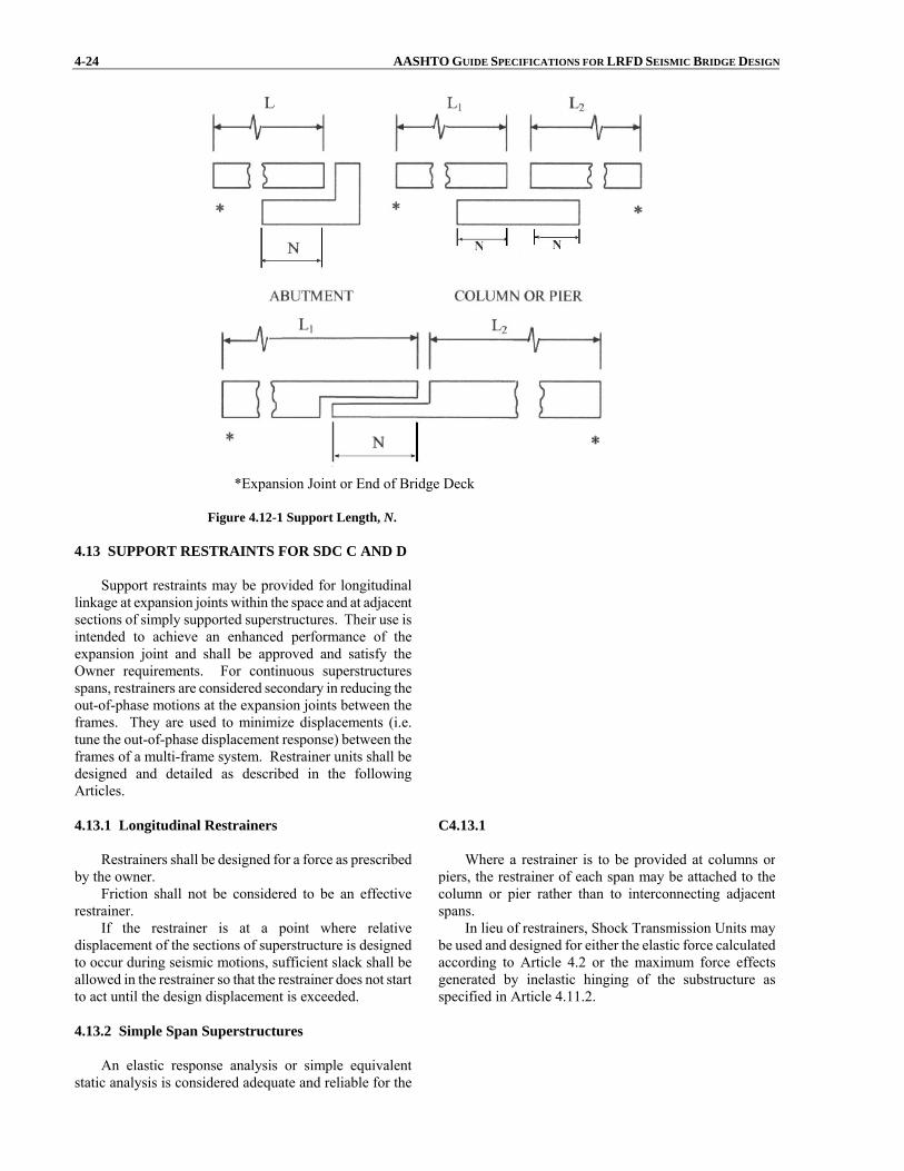
4-24 AASHTO GUIDE SPECIFICATIONS FOR LRFD SEISMIC BRIDGE DESIGN
*Expansion Joint or End of Bridge Deck Figure 4.12-1 Support Length, N.
4.13 SUPPORT RESTRAINTS FOR SDC C AND D
Support restraints may be provided for longitudinal linkage at expansion joints within the space and at adjacentsections of simply supported superstructures. Their use isintended to achieve an enhanced performance of theexpansion joint and shall be approved and satisfy theOwner requirements. For continuous superstructuresspans, restrainers are considered secondary in reducing theout-of-phase motions at the expansion joints between theframes. They are used to minimize displacements (i.e.tune the out-of-phase displacement response) between theframes of a multi-frame system. Restrainer units shall bedesigned and detailed as described in the following Articles.
4.13.1 Longitudinal Restrainers
Restrainers shall be designed for a force as prescribed
by the owner. Friction shall not be considered to be an effective
restrainer. If the restrainer is at a point where relative
displacement of the sections of superstructure is designedto occur during seismic motions, sufficient slack shall beallowed in the restrainer so that the restrainer does not startto act until the design displacement is exceeded.
C4.13.1 Where a restrainer is to be provided at columns or
piers, the restrainer of each span may be attached to the column or pier rather than to interconnecting adjacent spans.
In lieu of restrainers, Shock Transmission Units may be used and designed for either the elastic force calculated according to Article 4.2 or the maximum force effects generated by inelastic hinging of the substructure as specified in Article 4.11.2.
4.13.2 Simple Span Superstructures
An elastic response analysis or simple equivalentstatic analysis is considered adequate and reliable for the
SECTION 4: ANALYSIS AND DESIGN REQUIREMENTS 4-25 design of restrainers for simple spans. An acceleration coefficient not less than that specified in Article 4.5 shallbe used as a minimum.
4.13.3 Detailing Restrainers
• Restrainers shall be detailed to allow for easyinspection and replacement.
• Restrainer layout shall be symmetrical about the
centerline of the superstructure.
• Restrainer systems shall incorporate an adequategap for service conditions.
• Yield indicators may be used on cable restrainers
to facilitate post earthquake investigations.
4.14 SUPERSTRUCTURE SHEAR KEYS C4.14
The design of the superstructure and the substructure
shall take into consideration the anticipated load path. Forslender bents, shear keys on top of the bent cap mayfunction elastically at the design hazard level.
In lieu of experimental test data, the overstrengthshear key capacity, Vok, shall be taken as:
nok VV 2= (4.14-1) where: Vok = overstrength shear key capacity used in assessing the load path to adjacent capacity- protected members (kip) Vn = nominal interface shear capacity of shear key as defined in Article 5.8.4 of the AASHTO LRFD Bridge Design Specifications using the expected material properties and interface surface
conditions (kip) For shear keys at intermediate hinges within a span,
the designer shall assess the possibility of a shear keyfusing mechanism, which is highly dependent on out-of-phase frame movements. For bridges in SDC D whereshear keys are needed to achieve a reliable performance atthe design hazard level, (i.e., shear key element is part ofthe Earthquake Resistant System, ERS, see Article 3.3),non-linear analysis should be conducted to derive thedistribution forces on shear keys affected by out-of-phase motions.
Shear keys are typically designed to fuse at the design event earthquake level of acceleration. Minimum requirements herein are intended to keep the keys elastic at a lower more frequent earthquake event.

SECTION 5: ANALYTICAL MODELS AND PROCEDURES
TABLE OF CONTENTS
5-i
5.1 GENERAL........................................................................................................................................................ 5-1
5.1.1 Analysis of a Bridge ERS ....................................................................................................................... 5-1 5.1.2 Global Model .......................................................................................................................................... 5-2
5.2 ABUTMENTS .................................................................................................................................................. 5-3 5.2.1 General.................................................................................................................................................... 5-3 5.2.2 Wingwalls ............................................................................................................................................... 5-4 5.2.3 Longitudinal Direction............................................................................................................................ 5-4
5.2.3.1 Abutment Longitudinal Response for SDC B and C .................................................................... 5-5 5.2.3.2 Abutment Longitudinal Response for SDC D............................................................................... 5-5 5.2.3.3 Abutment Stiffness and Passive Pressure Estimate....................................................................... 5-6
5.2.4 Transverse Stiffness ................................................................................................................................ 5-9 5.2.4.1 Abutment Transverse Response for SDC B and C ....................................................................... 5-10
5.2.4.2 Abutment Transverse Response for SDC D.................................................................................. 5-10 5.3 FOUNDATIONS .............................................................................................................................................. 5-10
5.3.1 General.................................................................................................................................................... 5-10 5.3.2 Spread Footing........................................................................................................................................ 5-11 5.3.3 Pile Foundations ..................................................................................................................................... 5-12 5.3.4 Drilled Shafts .......................................................................................................................................... 5-12
5.4 ANALYTICAL PROCEDURES ...................................................................................................................... 5-12 5.4.1 General.................................................................................................................................................... 5-13 5.4.2 Procedure 1: Equivalent Static Analysis (ESA) ...................................................................................... 5-13 5.4.3 Procedure 2: Elastic Dynamic Analysis (EDA) ...................................................................................... 5-15 5.4.4 Procedure 3: Nonlinear Time History Method........................................................................................ 5-16
5.5 MATHEMATICAL MODELING USING EDA (PROCEDURE 2)................................................................ 5-17 5.5.1 General.................................................................................................................................................... 5-17 5.5.2 Superstructure ......................................................................................................................................... 5-17 5.5.3 Substructure ............................................................................................................................................ 5-18
5.6 EFFECTIVE SECTION PROPERTIES............................................................................................................ 5-18 5.6.1 Effective Reinforced Concrete Section Properties for Seismic Analysis ................................................ 5-18 5.6.2 EcIeff and (GA)eff for Ductile Reinforced Concrete Members................................................................... 5-18 5.6.3 Ieff for Box Girder Superstructures .......................................................................................................... 5-20 5.6.4 Ieff for Other Superstructure Types .......................................................................................................... 5-21 5.6.5 Effective Torsional Moment of Inertia ................................................................................................... 5-21

SECTION 5
ANALYTICAL MODELS AND PROCEDURES
5-1
5.1 GENERAL C5.1
A complete bridge system may be composed of a
single frame or a series of frames separated by expansion joints and/or articulated construction joints. A bridge iscomposed of a superstructure and a supporting substructure.
Individual frame sections are supported on theirrespective substructures. Substructures consist of piers,single column or multiple column bents that are supportedon their respective foundations.
The seismic response of a bridge includes the development of an analytical model followed by theresponse analysis of the analytical model to predict theresulting dynamic response for component design. Boththe development of the analytical model and the selectedanalysis procedure are dependent on the seismic hazard,selected seismic design strategy and the complexity of the bridge. There are various levels or degrees of refinementin the analytical model and analytical procedures that areavailable to the designer.
Seismic analysis encompasses a demand analysis and a displacement capacity verification. The objective of a demand analysis is to estimate the forces and displacements induced by the seismic excitation. A displacement capacity determination of piers and bents is required for SDC B, C, and D. The objective of a displacement capacity determination is to determine the displacement of an individual pier when its deformation capacity (that of the inelastic earthquake resisting element) is reached. The displacement capacity shall be greater than the displacement demand. The accuracy of the demand and capacity analyses depend on the assumption of the model related to the geometry, boundary conditions, material properties, and energy-dissipation incorporated in the model. It is the responsibility of the designer to assess the reasonableness of a model in representing the behavior of the structure at the level of forces and deformations expected for the seismic excitation.
Bridges should be analyzed accounting for nonlinear geometry (i.e., P-Δ effect). The need for modeling of foundations and abutments depends on the sensitivity of the structure to foundation flexibility and associated displacements. This in turn depends on whether the foundation is a spread footing, pile footing with pile cap, a pile bent, or drilled shaft. Article 5.3 defines the requirements for the foundation modeling in the seismic analysis.
When gross soil movement or liquefaction is determined to be possible, the model shall represent the change in support conditions and additional loads on the substructure associated with soil movement.
For structures whose response is sensitive to the support conditions, such as in a fixed-end arch, the model of the foundation shall account for the conditions present.
5.1.1 Analysis of a Bridge ERS
The entire bridge Earthquake Resistant System (ERS)for analysis purposes is referred to as the “global” model,whereas an individual bent or column is referred to as a“local” model. The term “global response” describes theoverall behavior of the bridge system including the effectsof adjacent components, subsystems, or boundaryconditions. The term “local response” referring to thebehavior of an individual component or subsystem beinganalyzed to determine, for example, its capacity using a pushover analysis.
Both global models and local models are included inthese Guide Specifications.
Individual bridge components shall have displacementcapacities greater than the displacement demands derived from the “global” analysis.
The displacement demands of a bridge system
5-2 AASHTO GUIDE SPECIFICATIONS FOR LRFD SEISMIC BRIDGE DESIGN consisting of multiple simple spans can be derived usingthe equivalent static analysis outlined in Article 5.4.2.Global analysis requirements as given in Article 5.1.2 neednot to be applied in this case. 5.1.2 Global Model
A global model should capture the response of theentire bridge system. Bridge systems with irregulargeometry, in particular curved bridges and skew bridges,will require a global model with actual geometry defined.Also, multiple transverse expansion joints, massivesubstructures components, and foundations supported bysoft soil can exhibit dynamic response characteristics thatshould be included in the model. Their effect on the globalresponse is not necessarily intuitively obvious and may notbe captured by a separate subsystem analysis.
Linear elastic dynamic analysis shall as a minimum beused for the global response analysis. There are however,some limitations in a linear elastic analysis approach. Thenonlinear response of yielding columns, gapped expansionjoints, earthquake restrainers and nonlinear soil propertiescan only be approximated using a linear elastic approach. Piece wise linear analysis can be used to approximatenonlinear response. Sensitivity studies using twobounding conditions may be used to approximate the non-linear effects.
For example, two global dynamic analyses arerequired to approximate the nonlinear response of a bridgewith expansion joints because it possesses differentcharacteristics in tension and compression.
In the tension model, the superstructure joints arepermitted to move independently of one another in thelongitudinal direction. Truss elements connecting thejoints may be used to model the effects of earthquakerestrainers. In the compression model, all of the truss(restrainer) elements are inactivated and the superstructureelements are locked longitudinally to capture structuralresponse modes where the joints close up, mobilizing theabutments when applicable.
The structure’s geometry will generally dictate if botha tension model and a compression model are required. Structures with appreciable superstructure curvature have abias response to the outside of the curve and may requireadditional models, which combine the characteristics identified for the tension and compression models.
Long multi-frame bridges may be analyzed withmultiple elastic models. A single multi-frame model maynot be realistic since it cannot account for out-of-phase movement among the frames.
Each multi-frame model may be limited to five framesplus a boundary frame or abutment on each end of themodel. Adjacent models shall overlap each other by atleast one useable frame, as shown in Figure 1. A masslessspring should be attached to the dead end of the boundaryframes to represent the stiffness of the adjoining structure. The boundary frames provide some continuity betweenadjacent models but are considered redundant and their
C5.1.2
Depending on the chosen seismic analysis method, different types of approximations may be used for modeling the strength, stiffness, and energy-dissipation mechanisms. One-dimensional beam-column elements are sufficient for dynamic analysis of structures due to earthquake ground motion (referred to as “spine” models or “stick” models). For seismic analyses, grid or finite-element analyses are generally not necessary. They greatly increase the size of the model and complicate the understanding of the force and deformation distribution through the substructure because of the large number of vibration modes.
The geometry of skew, horizontal curvature, and joint size should be included in the model. However, two-dimensional models are adequate for bridges with skew angle less than 30° and a subtended angle of horizontal curvature less than 20°. When skew is included in a three-dimensional model, the geometry and boundary conditions at the abutments and bearings should be represented in order to determine the forces and displacements at these locations. Short columns or piers may be modeled with a single element, but tall columns may have two or more elements, particularly if they have significant mass (in the case of concrete), or are modeled as framed substructures.
The use of compression and tension models is expected to provide a reasonable bound on forces (compression model) and displacements (tension model).

SECTION 5: ANALYTICAL MODELS AND PROCEDURES 5-3 analytical results are ignored. Tran. 1
Long. 2
Long. 1
Tran. 2
Boundary Frame 3
Boundary Frame 2
Tran. 3
Long. 3
Boundary Frame 2
Boundary Frame 1
Legend
Long.: Longitudinal Axis
Tran.: Transverse Axis
Bridge Expansion Joint
Abut
Abut
Model 1
Model 2
Model 3
Figure 5.1.2-1 Elastic Dynamic Analysis Modeling Technique.
5.2 ABUTMENTS
5.2.1 General
The model of the abutment shall reflect the expected behavior of the abutment with seismic loads applied ineach of the two horizontal directions. Resistance ofstructural components shall be represented by crackedsection properties where applicable when conducting anEquivalent Static Analysis or an Elastic DynamicAnalysis.
The resistance from passive pressure of the soilembankment at the abutment wall shall be represented by avalue for the secant stiffness consistent with the maximumdisplacement – according to Article 5.2.3. Depending on the bridge configuration, one of two alternatives can bechosen by the designer:
Earthquake Resisting System (ERS) withoutAbutment Contribution. ERS is designed to resistall seismic loads without any contribution fromabutments in either orthogonal direction. Earthquake Resisting System (ERS) with
C5.2.1
Article 5.2 provides requirements for the modeling of abutments in the longitudinal and transverse directions. The iterative procedure with secant stiffness coefficients defined in those articles are included in the mathematical model of the bridge to represent the resistance of the abutments in an elastic analysis.
The load-displacement behavior of the abutment may be used in a static nonlinear analysis when the resistance of the abutment is included in the design of the bridge.
In general the connections between the superstructure and substructure should be designed for the maximum forces that could be developed. In the spirit of capacity design, this implies that the forces corresponding to the full plastic mechanism (with yielding elements at their overstrength condition) should be used to design the connections. In cases where the full plastic mechanism might not develop during the Design Earthquake, the elastic forces for this event are permitted. However, it is still good practice to design the connections to resist the higher forces corresponding to the full plastic mechanism.
5-4 AASHTO GUIDE SPECIFICATIONS FOR LRFD SEISMIC BRIDGE DESIGN
Abutment Contribution. The ERS is designed withthe abutments as a key element of the ERS, in one orboth of the orthogonal directions. Abutments aredesigned and analyzed to sustain the Design Earthquake displacements.
For the Displacement Capacity Verification, the
strength of each component in the abutment, including soil, shall be included.
It is also good practice to design for the best estimate of forces that might develop in cases such as pile bents with battered piles. In such bents the connections should be stronger than the expected forces, and these forces may be large and may have large axial components. In such cases, the plastic mechanism may be governed by the pile geotechnical strengths, rather than the pile structural strengths.
5.2.2 Wingwalls
The participation of abutment walls and wingwalls in the overall dynamic response of bridge systems toearthquake loading and in providing resistance toseismically induced inertial loads shall be considered inthe seismic design of bridges. Damage to walls is allowedto occur during earthquakes considering No Collapsecriteria. Abutment participation in the overall dynamicresponse of the bridge system shall reflect the structuralconfiguration, the load-transfer mechanism from the bridgeto the abutment system, the effective stiffness and forcecapacity of the wall-soil system, and the level of expected abutment damage. The capacity of the abutments to resistthe bridge inertial load shall be compatible with thestructural design of the abutment wall (i.e., whether part ofthe wall will be damaged by the design earthquake), aswell as the soil resistance that can be reliably mobilized. The lateral load capacity of walls shall be evaluated basedon an applicable passive earth-pressure theory.
C5.2.2
A simplistic approach that may be used is to consider one wall 2/3 effective in acting against the abutment soil fill, while the second wall is considered 1/3 effective in acting against the outside sloped berm.
5.2.3 Longitudinal Direction
Under earthquake loading, the earth pressure action onabutment walls changes from a static condition to one ofgenerally two possible conditions; (1) the dynamic activepressure condition as the wall moves away from thebackfill, or (2) the passive pressure condition as the inertialload of the bridge pushes the wall to move inward towardthe backfill. The governing earth pressure conditiondepends on the magnitude of seismically inducedmovement of the abutment walls, the bridgesuperstructure, and the bridge/abutment configuration. Forseat-type abutments where the expansion joint issufficiently large to accommodate both the cyclicmovement between the abutment wall and the bridgesuperstructure (i.e., superstructure does not push againstabutment wall), the seismically induced earth pressure onthe abutment wall would be the dynamic active pressure condition. However, when the gap at the expansion joint isnot sufficient to accommodate the cyclic wall/bridgemovements, a transfer of forces will occur from thesuperstructure to the abutment wall. As a result, the activeearth pressure condition will not be valid and the earthpressure approaches a much larger passive pressure loadcondition behind the backwall, which is the main cause forabutment damage as witnessed in past earthquakes. Forstub or integral abutments, the abutment stiffness and
SECTION 5: ANALYTICAL MODELS AND PROCEDURES 5-5 capacity under passive pressure loading are primary design concerns.
5.2.3.1 Abutment Longitudinal Response for SDCB and C
Backwall reinforcement of seat-type abutments or the
diaphragm of integral abutments designed primarily fornon-seismic load conditions shall be checked for theseismic load path and altered if deemed appropriate.
C5.2.3.1 Abutments designed for bridges in SDC B or C are
expected to resist earthquake loads with minimal damage. For seat-type abutments, minimal abutment movement could be expected under dynamic passive pressure conditions. However, bridge superstructure displacement demands may be 4 in. or more and could potentially increase the soil mobilization.
The provisions of Article 5.2.3.2 may be used for the design of abutments for bridges in SDC B or C.
5.2.3.2 Abutment Longitudinal Response for SDCD
For SDC D, passive pressure resistance in soils behindintegral abutment walls and back walls for seat abutmentswill usually be mobilized due to the large longitudinal superstructure displacements associated with the inertialloads. Two alternatives may be considered by theDesigner:
Case 1: Earthquake Resisting System (ERS)without Abutment Contribution. The bridge ERS isdesigned to resist all seismic loads without any contribution from abutments. Abutments maycontribute to limiting displacement, providing additional capacity, and better performance that is notdirectly accounted for in the analytical model. Toensure that the columns will be able to resist the lateral loads, a zero stiffness and capacity at theabutments should be assumed. In this case, anevaluation of the abutment which considers theimplications of significant displacements from seismicaccelerations should be conducted. As appropriate,this evaluation should include overturning forabutments on spread footings or other structuralconfigurations where overturning may be a concern.

5-6 AASHTO GUIDE SPECIFICATIONS FOR LRFD SEISMIC BRIDGE DESIGN
Case 2: Earthquake Resisting System (ERS) withAbutment Contribution. In this case, the bridge isdesigned with the abutments as a key element of theERS. Abutments are designed and analyzed to sustainthe Design Earthquake displacements. Whenabutment stiffness and capacity are included in thedesign, it should be recognized that the passivepressure zone mobilized by abutment displacementextends beyond the active pressure zone normallyused for static service load design, as illustratedschematically in Figure 1. The approach slab shown inFigure 1 is for illustration purposes only. Whetherpresumptive or computed passive pressures are usedfor design as stated in Article 5.2.3.3, backfill in thiszone should be controlled by specifications, unless thepassive pressure considered is less than 70% of thepresumptive value.
Figure 5.2.3.2-1 Design Passive Pressure Zone.
5.2.3.3 Abutment Stiffness and Passive PressureEstimate Abutment stiffness, Keff in kip/ft., and passive
capacity, Pp in kips, should be characterized by a bi-linear or other higher-order nonlinear relationship as shown inFigure 1. Passive pressures may be assumed uniformlydistributed over the height (Hw) of the backwall ordiaphragm. Thus the total passive force is:
wwpp WHpP = (5.2.3.3-1) where: pp = passive lateral earth pressure behind backwall (ksf) Hw = height of backwall (ft.) Ww = width of backwall (ft.)
C5.2.3.3
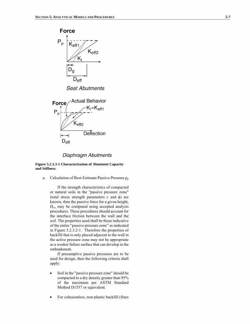
SECTION 5: ANALYTICAL MODELS AND PROCEDURES 5-7
Figure 5.2.3.3-1 Characterization of Abutment Capacity and Stiffness.
a. Calculation of Best-Estimate Passive Pressure pp
If the strength characteristics of compactedor natural soils in the "passive pressure zone"(total stress strength parameters c and φ) are known, then the passive force for a given height,Hw, may be computed using accepted analysisprocedures. These procedures should account forthe interface friction between the wall and the soil. The properties used shall be those indicativeof the entire “passive pressure zone” as indicatedin Figure 5.2.3.2-1. Therefore the properties ofbackfill that is only placed adjacent to the wall inthe active pressure zone may not be appropriate as a weaker failure surface that can develop in theembankment.
If presumptive passive pressures are to beused for design, then the following criteria shallapply:
• Soil in the "passive pressure zone" should be
compacted to a dry density greater than 95% of the maximum per ASTM StandardMethod D1557 or equivalent.
• For cohesionless, non-plastic backfill (fines

5-8 AASHTO GUIDE SPECIFICATIONS FOR LRFD SEISMIC BRIDGE DESIGN
content less than 30%), the passive pressurepp may be assumed equal to 2Hw/3 ksf perfoot of wall length.
• For cohesive backfill (clay fraction > 15%),
the passive pressure pp may be assumedequal to 5 ksf provided the estimatedundrained shear strength is greater than 4ksf.
The presumptive values given above are
applicable for use in the “Permissible EarthquakeResisting Elements that Require Owner’sApproval”, as defined in Article 3.3. If thedesign is based upon presumptive resistances thatare not greater than 70% of the values listedabove, then the structure may be classified in the“Permissible Earthquake Resisting Elements”.
In all cases granular drainage material shallbe placed behind the abutment wall to ensureadequate mobilization of wall friction.
b. Calculation of Soil Stiffness
An equivalent linear secant stiffness, Keff in
kip/ft., is required for analyses. For integral ordiaphragm type abutments, an initial secantstiffness (Figure 1) may be calculated as follows:
( )ww
peff HF
PK =1 (5.2.3.3-2)
where: Pp = passive lateral earth pressure capacity (kip) Hw = height of backwall (ft.) Fw = factor taken as between 0.01 to 0.05 for soils ranging from dense sand to compacted clays
If computed abutment forces exceed the soilcapacity, the stiffness should be softenediteratively (Keff1 to Keff2) until abutmentdisplacements are consistent (within 30%) withthe assumed stiffness. For seat type abutmentsthe expansion gap should be included in theinitial estimate of the secant stiffness. Thus:
( )gww
peff DHF
PK
+=1 (5.2.3.3-3)
where: Dg = width of gap between backwall and
Guidance on the value of Fw to use for a particular
bridge may be found in Table C3.11.1-1 of the AASHTOLRFD Bridge Design Specifications. The table presents values of Fw for dense sand, medium dense sand, loose sand, compacted silt, compacted lean clay, and compacted fat clay. If the influence of passive pressure extends beyond one particular soil type at an abutment, averaged or weighted average values for Fw may be used at the engineer’s discretion.
SECTION 5: ANALYTICAL MODELS AND PROCEDURES 5-9 superstructure (ft.)
For SDC D, where pushover analyses areconducted, values of Pp and the initial estimate of Keff1should be used to define a bilinear load-displacement behavior of the abutment for the capacity assessment.
5.2.4 Transverse Stiffness
Two alternatives may be considered by the designer: Case 1: Earthquake Resisting System (ERS)without Abutment Contribution. The bridge ERS isdesigned to resist all seismic loads without anycontribution from abutments. Concrete Shear Keys areconsidered sacrificial when they are designed for lateral loads lower than the Design Earthquake loads.A minimum level of design corresponds to lateralloads not including earthquake loads. If sacrificialconcrete shear keys are used to protect the piles, thebridge shall be analyzed and designed according toArticles 5.2.4.1 and 5.2.4.2 as applicable. If a fuse isused, then the effects of internal force redistributionresulting from fusing shall be taken into account in thedesign of the bridge. Limitations on the use of fusing(hinging or failure of a bridge component along theearthquake load path) for SDC C or D are listedbelow. Abutment pile foundations are consideredadequate to carry the vertical dead loads for satisfyingthe No Collapse Criteria. Case 2: Earthquake Resisting System (ERS) withAbutment Contribution. The bridge is designedwith the abutments as a key element of the ERS.Shear keys at the abutment are designed and analyzedto sustain the lesser of the Design Earthquake forcesor sliding friction forces of spread footings. Pile supported foundations are designed to sustain theDesign Earthquake displacements. Inelastic behaviorof piles at the abutment is acceptable.
In the context of these provisions, elastic resistance
includes the use of elastomeric, sliding, or isolation bearings designed to accommodate the designdisplacements, soil frictional resistance acting against the base of a spread footing-supported abutment, pile resistance provided by piles acting in their elastic range, orpassive resistance of soil acting at displacements less that2% of the wall height.
Likewise, fusing includes: breakaway elements, suchas isolation bearings with a relatively high yield force;shear keys; yielding elements, such as wingwalls yieldingat their junction with the abutment backwall; elastomericbearings whose connections have failed and upon whichthe superstructure is sliding; spread footings that areproportioned to slide; or piles that develop a complete plastic mechanism.
The stiffness of the abutment foundation under
5-10 AASHTO GUIDE SPECIFICATIONS FOR LRFD SEISMIC BRIDGE DESIGN transverse loading may be calculated based on theprocedures given in Article 5.3. Where fusing elements are used, allowance shall be made for the reducedequivalent stiffness of the abutment after fusing occurs.
5.2.4.1 Abutment Transverse Response for SDC B and C Shear keys shall be designed to resist a horizontal
seismic force not less than the product of the effectivepeak ground spectral acceleration coefficient, 0.4SDS, as specified in Article 3.4, times the tributary permanent load.
Fusing is not expected for SDC B or C; however, if deemed necessary, shall be checked using the procedureapplicable to SDC D according to Article 5.2.4.2 takinginto account the overstrength effects of shear keysaccording to Article 4.14.
C5.2.4.1
For bridges in these categories, elastic resistance may be achievable.
5.2.4.2 Abutment Transverse Response for SDC D For structures in this category, either elastic resistance
or fusing shall be used to accommodate transverseabutment loading. The elastic forces used for transverseabutment design shall be determined from an elastic demand analysis of the structure.
For transverse loading when a fusing mechanism is chosen for pile support foundations, the overstrength capacity of the shear keys shall be less than the combinedplastic shear capacity of the piles. For pile-supportedabutment foundations, the stiffness contribution ofstandard size piles (i.e., ≤ 16 in.) shall be ignored if theabutment displacement is greater than 4 in. unless adisplacement capacity verification of the pile is performedseparately. The capacity provided by the footing-soil friction resistance in addition to the wing walls resistanceis considered secondary for ensuring a fusing mechanism.
The design of concrete shear keys should consider theunequal forces that may develop in a skewed abutment,particularly if the intermediate piers are also skewed. (Thiseffect is amplified if intermediate piers also have unequalstiffness, such as wall piers.) The shear key design shouldalso consider unequal loading if multiple shear keys areused. The use of recessed or hidden shear keys should beavoided if possible, since these are difficult to inspect andrepair.
5.3 FOUNDATIONS 5.3.1 General
The Foundation Modeling Method (FMM) defined in Table 1 is recommended unless deemed otherwise.Articles 5.3.2, 5.3.3 and 5.3.4 provide the requirements forestimating foundation springs for spread footings, pilefoundations, and the depth to fixity for drilled shafts, respectively. For a foundation considered as rigid, themass of the foundation should be ignored in the analyticalmodel. The Engineer shall assess the merits of including
C5.3.1
A wide range of methods for modeling foundations for seismic analysis is available. Generally a refined model is unnecessary for seismic analysis. For many cases the assumption of a rigid foundation is adequate. Flexibility of a pile bent or shaft can be estimated using an assumed point-of-fixity associated with the stiffness estimate of the pile (or shaft) and the soil. Spread footings and piles can be modeled with rotational and translational springs.
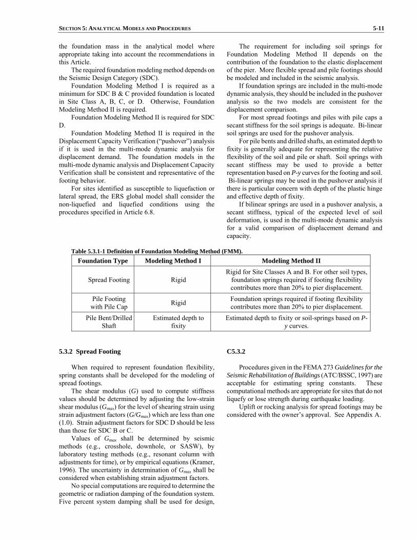
SECTION 5: ANALYTICAL MODELS AND PROCEDURES 5-11 the foundation mass in the analytical model whereappropriate taking into account the recommendations inthis Article.
The required foundation modeling method depends on the Seismic Design Category (SDC).
Foundation Modeling Method I is required as aminimum for SDC B & C provided foundation is locatedin Site Class A, B, C, or D. Otherwise, FoundationModeling Method II is required.
Foundation Modeling Method II is required for SDCD.
Foundation Modeling Method II is required in the Displacement Capacity Verification (“pushover”) analysis if it is used in the multi-mode dynamic analysis fordisplacement demand. The foundation models in themulti-mode dynamic analysis and Displacement CapacityVerification shall be consistent and representative of thefooting behavior.
For sites identified as susceptible to liquefaction or lateral spread, the ERS global model shall consider thenon-liquefied and liquefied conditions using theprocedures specified in Article 6.8.
The requirement for including soil springs for Foundation Modeling Method II depends on the contribution of the foundation to the elastic displacement of the pier. More flexible spread and pile footings should be modeled and included in the seismic analysis.
If foundation springs are included in the multi-mode dynamic analysis, they should be included in the pushover analysis so the two models are consistent for the displacement comparison.
For most spread footings and piles with pile caps a secant stiffness for the soil springs is adequate. Bi-linear soil springs are used for the pushover analysis.
For pile bents and drilled shafts, an estimated depth to fixity is generally adequate for representing the relative flexibility of the soil and pile or shaft. Soil springs with secant stiffness may be used to provide a better representation based on P-y curves for the footing and soil. Bi-linear springs may be used in the pushover analysis if there is particular concern with depth of the plastic hinge and effective depth of fixity.
If bilinear springs are used in a pushover analysis, a secant stiffness, typical of the expected level of soil deformation, is used in the multi-mode dynamic analysis for a valid comparison of displacement demand and capacity.
Table 5.3.1-1 Definition of Foundation Modeling Method (FMM).
Foundation Type Modeling Method I Modeling Method II
Spread Footing Rigid Rigid for Site Classes A and B. For other soil types,
foundation springs required if footing flexibility contributes more than 20% to pier displacement.
Pile Footing with Pile Cap Rigid Foundation springs required if footing flexibility
contributes more than 20% to pier displacement.
Pile Bent/Drilled Shaft
Estimated depth to fixity
Estimated depth to fixity or soil-springs based on P-y curves.
5.3.2 Spread Footing
When required to represent foundation flexibility, spring constants shall be developed for the modeling ofspread footings.
The shear modulus (G) used to compute stiffness values should be determined by adjusting the low-strain shear modulus (Gmax) for the level of shearing strain usingstrain adjustment factors (G/Gmax) which are less than one(1.0). Strain adjustment factors for SDC D should be lessthan those for SDC B or C.
Values of Gmax shall be determined by seismicmethods (e.g., crosshole, downhole, or SASW), by laboratory testing methods (e.g., resonant column withadjustments for time), or by empirical equations (Kramer, 1996). The uncertainty in determination of Gmax shall be considered when establishing strain adjustment factors.
No special computations are required to determine the geometric or radiation damping of the foundation system.Five percent system damping shall be used for design,
C5.3.2
Procedures given in the FEMA 273 Guidelines for the Seismic Rehabilitation of Buildings (ATC/BSSC, 1997) are acceptable for estimating spring constants. These computational methods are appropriate for sites that do not liquefy or lose strength during earthquake loading.
Uplift or rocking analysis for spread footings may be considered with the owner’s approval. See Appendix A.
5-12 AASHTO GUIDE SPECIFICATIONS FOR LRFD SEISMIC BRIDGE DESIGN unless special studies are performed and approved by theowner.
Moment-rotation and shear force-displacement shall be represented by a bi-linear relationship. The initial slopeof the bi-linear curve should be defined by a rotationalspring constant.
The maximum resisting force (i.e., plastic capacity) onthe force-deformation curve shall be defined for the best-estimate case of geotechnical properties.
5.3.3 Pile Foundations
The design of pile foundations shall be based oncolumn loads determined by capacity design principles (Article 4.11) or elastic seismic forces, whichever issmaller for SDC B and based on capacity design principlesonly for SDC C or D. Both the structural and geotechnicalelements of the foundation shall be designed accordingly.
Foundation flexibility shall be incorporated intodesign for SDC D according to Article 5.3.1.
The nonlinear properties of the piles shall beconsidered in evaluating the lateral response of the piles tolateral loads during a seismic event.
Liquefaction shall be considered using procedures specified in Article 6.8 for SDC D where applicable duringthe development of spring constants and capacity values.
C5.3.3
A group reduction factor established in the geotechnical report should be considered in the analysis. Analyzing the structure with and without consideration of a group reduction factor should also be considered since the overall response of the structure for these two cases may vary significantly.
5.3.4 Drilled Shafts
The flexibility of the drilled shaft shall be representedusing either the estimated depth of fixity or soil springs ina lateral pile analysis. Procedures identified in Article5.3.3 including those for liquefaction, generally applyexcept that group reduction factors are typically consideredonly in the transverse direction of a multi-shaft bent.
5.4 ANALYTICAL PROCEDURES C5.4
In specifying the Seismic Design Category (SDC),
two principles are followed. First, as the seismic hazard increases, improved modeling and analysis for seismic demands is necessary because the behavior may be sensitive to the maximum demands. Second, as the complexity of the bridge increases, more sophisticated models are required for seismic demand and displacement capacity evaluation. For bridges with a regular configuration, a single-degree-of-freedom model is sufficiently accurate to represent the seismic response. For these types of bridges, the equivalent static analysis (Procedure 1) may be used to establish displacement demands.
For structures that do not satisfy the requirements of regularity for an elastic response spectrum analysis, Procedure 2, shall be used to determine the displacement demands
SECTION 5: ANALYTICAL MODELS AND PROCEDURES 5-13 5.4.1 General
The objective of seismic analysis is to assessdisplacement demands of a bridge and its individualcomponents. Equivalent static analysis and linear elasticdynamic analysis are the appropriate analytical tools forestimating the displacement demands for normal bridges.Inelastic static analysis “Pushover Analysis” is theappropriate analytical tool used to establish thedisplacement capacities for normal bridges assigned toSDC D.
Nonlinear Time History analysis should be used forcritical or essential bridges as defined in Article 4.2.2 and in some cases for Normal Bridges in SDC D using devicesfor isolation or energy dissipation. In this type of analysis,component capacities are characterized in themathematical model used for the seismic responseanalysis. The procedures mentioned above are describedin more detail below in Article 5.4.4.
5.4.2 Procedure 1: Equivalent Static Analysis (ESA)
ESA can be used to estimate displacement demands for structures where a more sophisticated dynamic analysiswill not provide additional insight into behavior. ESA isbest suited for structures or individual frames with wellbalanced spans and uniformly distributed stiffness wherethe response can be captured by a predominanttranslational mode of vibration.
Both the Uniform Load Method and the Single ModeSpectral Analysis Method are considered acceptableequivalent static analysis procedures.
The Uniform Load Method shall be based on thefundamental mode of vibration in either the longitudinal ortransverse direction. The period of this mode of vibrationshall be taken as that of an equivalent single mass-spring oscillator. The stiffness of this equivalent spring shall becalculated using the maximum displacement that occurswhen an arbitrary uniform lateral load is applied to thebridge. A procedure for using the Uniform Load Methodis given in Article C5.4.2.
The Single-Mode Spectral Analysis Method shall bebased on the fundamental mode of vibration in either thelongitudinal or transverse direction. This mode shape maybe found by applying a uniform horizontal load to thestructure and calculating the corresponding deformedshape. The natural period may be calculated by equatingthe maximum potential and kinetic energies associatedwith the fundamental mode shape. A procedure for using the Single-Mode Spectral Analysis Method can be foundin the AASHTO LRFD Bridge Design SpecificationsArticle 4.7.4.3.2b.
C5.4.2
The equivalent static analysis is suitable for short to medium span structures with regular configuration. Long bridges, or those with significant skew or horizontal curvature, have dynamic characteristics that should be assessed in a multi-mode dynamic analysis.
The Uniform Load Method, described in the following steps, may be used for both transverse and longitudinal earthquake motions. It is essentially an equivalent static method of analysis that uses a uniform lateral load to approximate the effect of seismic loads. The method is suitable for regular bridges that respond principally in their fundamental mode of vibration.
Whereas displacements are calculated with reasonable accuracy, the method can overestimate the transverse shears at the abutments by up to 100%. Consequently, the columns may have inadequate lateral strength because of the overestimate of abutment forces. The Single-Mode Spectral Analysis Method or a multi-mode dynamic analysis is recommended to avoid unrealistic distributions of seismic forces. The steps in the uniform load method are as follows:
1. Calculate the static displacements vs(x) due to an assumed uniform load po, as shown in Figure C1. The uniform loading po is applied over the length of the bridge; it has dimension of force/unit length and may be arbitrarily set equal to 1.0. The static displacement vs(x) has the dimension of length.
2. Calculate the bridge lateral stiffness, K, and total
weight, W, from the following expressions:
max,s
o
vLpK = (C5.4.2-1)

5-14 AASHTO GUIDE SPECIFICATIONS FOR LRFD SEISMIC BRIDGE DESIGN
∫=L
dxxwW0
)( (C5.4.2-2)
where: po = uniform lateral load applied over the length of the structure (kip/ft. or kip/in.) L = total length of the structure (ft. or in.) vs,max = maximum lateral displacement due to uniform load po (ft. or in.) w(x) = nominal dead load of the bridge superstructure and tributary substructure (kip/ft. or kip/in.) W = total weight of structure (kip) K = effective lateral bridge stiffness (kip/ft. or kip/in.)
The weight shall take into account structural elements and other relevant loads including, butnot limited to, pier caps, abutments, columns, and footings. Other loads, such as live loads, may be included.
3. Calculate the period of the bridge, Tm, using the
expression:
KgWTm π= 2 (C5.4.2-3)
where: g = acceleration due to gravity (ft./sec.2 or in./sec.2)
4. Calculate the equivalent static earthquake loading pe from the expression:
LWSp a
e = (C5.4.2-4)
where: Sa = design response spectral acceleration coefficient determined in accordance with Article 3.4.1 for T=Tm pe = equivalent uniform static lateral seismic load per unit length of bridge applied to represent the primary mode of vibration

SECTION 5: ANALYTICAL MODELS AND PROCEDURES 5-15
(kip/ft. or kip/in.)
5. Calculate the displacements and member forces for use in design either by applying pe to the structure and performing a second static analysis or by scaling the results of the first step above by the ratio pe /po.
The configuration requirements for Equivalent Static
Analysis (Procedure 1) analysis restrict application to individual frames or units that can be reasonably assumed to respond as a single-degree-of-freedom system in the transverse and longitudinal directions. When abutments do not resist significant seismic forces, the superstructure will respond as a rigid-body mass. The lateral-load-resisting piers or bents should be uniform in strength and stiffness to justify the assumption of independent transitional response in the longitudinal and transverse directions.
Figure C5.4.2-1 Bridge Deck Subjected to Assumed Transverse and Longitudinal Loading.
5.4.3 Procedure 2: Elastic Dynamic Analysis (EDA)
EDA shall be used to estimate the displacementdemands for structures where ESA does not provide anadequate level of sophistication to estimate the dynamic behavior. A linear elastic multi-modal spectral analysis utilizing the appropriate response spectrum (i.e., 5%damping) shall be performed. The number of degrees of freedom and the number of modes considered in the analysis shall be sufficient to capture at least 90% massparticipation in both the longitudinal and transversedirections. A minimum of three elements per flexible
C5.4.3
The model for an elastic response spectrum analysis is linear, and as such it does not represent the inelastic behavior of earthquake-resisting elements under strong ground motion. However, with the proper representation of the inelastic elements and interpretation of responses, an elastic analysis provides reasonable estimates of seismic demands. The model should be based on cracked section properties for concrete components, and on secant stiffness coefficients for the foundations, abutments, and seismic isolation components. All shall be consistent with the
5-16 AASHTO GUIDE SPECIFICATIONS FOR LRFD SEISMIC BRIDGE DESIGN column and four elements per span shall be used in thelinear elastic model.
The engineer should recognize that forces generated by linear elastic analysis could vary, depending on thedegree of non-linear behavior, from the actual forcedemands on the structure. Displacements are not assensitive to the non-linearity’s and may be consideredgood approximations. Sources of nonlinear response thatare not captured by EDA include the effects of thesurrounding soil, yielding of structural components,opening and closing of expansion joints, and nonlinearrestrainer and abutment behavior. EDA modal results shallbe combined using the complete quadratic combination(CQC) method.
For multi-frame analysis it is recommended to includea minimum of two boundary frames or one frame and anabutment beyond the frame user consideration. (SeeArticle 5.1.2).
expected levels of deformation of the components. The displacements at the center of mass, generally the superstructure, can be used to estimate the displacement demand of the structure including the effect of inelastic behavior in the earthquake-resisting elements.
For SDC D, a displacement capacity evaluation is required. The displacement capacity evaluation involves determining the displacement at which the first component reaches its inelastic deformation capacity. All non-ductile components shall be designed using capacity design principles to avoid brittle failure. For simple piers or bents, the displacement capacity can be evaluated by simple calculations using the geometry of displaced shapes, and forces and deformations at the plastic hinges. For more complicated piers or bents, particularly when foundations and abutments are included in the model, a nonlinear static (“pushover”) analysis may be used to evaluate the displacement capacity. It is recommended that the nonlinear static analysis continue beyond the displacement at which the first component reaches its inelastic deformation capacity in order to assess the behavior beyond the displacement capacity and obtain a better understanding of the limit states.
The displacement capacity is compared to the displacement demand determined from an elastic response-spectrum analysis.
Vibration modes are convenient representations of dynamic response for response spectrum analysis. Enough modes should be included to provide sufficient participation for bending moments in columns, or other components with inelastic deformation. Dynamic analysis programs, however, usually compute participation factors only for base shear, often expressed as a percentage of total mass. For regular bridges the guideline of including 90% of the modal mass for horizontal components generally provides a sufficient number of modes for accurate estimate of forces in lateral-load-resisting components. For irregular bridges, or large models of multiple-frame bridges, the participating mass may not indicate the accuracy for forces in specific components. It is for this reason that the models of long bridges are limited to five frames.
The response spectrum in Article 3.4.1 is based on 5% damping. For bridges with seismic isolation the additional damping from the seismic isolator units applies only to the isolated vibration modes. Other vibration modes have 5% damping.
5.4.4 Procedure 3: Nonlinear Time History Method
Any step-by-step, time history method of dynamic analysis that has been validated by experiment and/orcomparative performance with similar methods may beused provided the following requirements are also satisfied.
The time histories of input acceleration used todescribe the earthquake loads shall be selected inconsultation with the Owner or Owner’s representative.
C5.4.4
A nonlinear dynamic analysis is a more comprehensive analysis method because the effect of inelastic behavior is included in the demand analysis. Depending on the mathematical model, the deformation capacity of the inelastic elements may or may not be included in the dynamic response analysis. A nonlinear dynamic response analysis requires a suite of time-histories (Article 3.4.4) of earthquake ground motion that

SECTION 5: ANALYTICAL MODELS AND PROCEDURES 5-17 Time-History Analysis shall be performed with no fewerthan three data sets (two horizontal components and one vertical component) of appropriate ground motion time histories selected and called from not less than threerecorded events. Appropriate time histories shall representmagnitude, fault distances and source mechanisms that areconsistent with those that control the design earthquake ground motion. Each time history shall be modified to beresponse-spectrum compatible using the time-domain procedure.
Where three time history data sets are used in theanalysis of a structure, the maximum value of eachresponse parameter (e.g., force in a member, displacement at a specific level) shall be used to determine designacceptability. Where seven or more time history data setsare employed, the average value of each responseparameter may be used to determine design acceptability.The sensitivity of the numerical solution to the size of thetime step used for the analysis shall be determined. Asensitivity study shall also be carried out to investigate theeffects of variations in assumed material properties.
is representative of the hazard and conditions at the site. Because of the complexity involved with nonlinear dynamic analysis, it is best used in conjunction with SDC D or in a case where seismic isolation is included in thedesign strategy.
Seismically isolated structures with long periods or large damping ratios require a nonlinear dynamic analysis because the analysis procedures using an effective stiffness and damping may not properly represent the effect of isolation units on the response of the structure. The model for nonlinear analysis shall represent the hysteretic relationships for the isolator units.
5.5 MATHEMATICAL MODELING USING EDA(PROCEDURE 2)
5.5.1 General
The bridge should be modeled as a three-dimensional space frame with joints and nodes selected to realisticallymodel the stiffness and inertia effects of the structure.Each joint or node should have six degrees-of-freedom, three translational and three rotational. The structuralmass should be lumped with a minimum of threetranslational inertia terms at each node.
The mass should take into account structural elementsand other relevant loads including, but not limited to, piercaps, abutments, columns and footings. Other loads suchas live loads may be included. Generally, the inertiaeffects of live loads are not included in the analysis;however, the probability of a large live load being on the bridge during an earthquake should be considered whendesigning bridges with high live-to-dead load ratios whichare located in metropolitan areas where traffic congestion is likely to occur.
C5.5.1
For elastic analysis methods, there is a significant approximation in representing the force-deformation relationship of inelastic structural elements by a single linearized stiffness. For inelastic columns or other inelastic earthquake-resisting elements, the common practice is to use an elastic stiffness for steel elements and a cracked stiffness for reinforced concrete elements. However, the stiffness of seismic isolator units, abutments, and foundation soils are represented by a secant stiffness consistent with the maximum deformation. The designer shall consider the distribution of displacements from an elastic analysis to verify that they are consistent with the inelastic behavior of the earthquake-resisting elements.
The objective of the nonlinear displacement capacity verification is to determine the displacement at which the inelastic components reach their deformation capacity. The deformation capacity is the sum of elastic and plastic deformations. The plastic deformation is expressed in terms of the rotation of the plastic hinges. A nonlinearanalysis using expected strengths of the components gives larger plastic deformations than an analysis including overstrength. Hence, it is appropriate to use the expected strength of the components when estimating the displacement capacity.
5.5.2 Superstructure
The superstructure shall, as a minimum, be modeledas a series of space frame members with nodes at suchpoints as the span quarter points in addition to joints at the
C5.5.2
For a spine or stick model of the superstructure, the stiffness is represented by equivalent section properties for axial deformation, flexure about two axes, torsion, and
5-18 AASHTO GUIDE SPECIFICATIONS FOR LRFD SEISMIC BRIDGE DESIGN ends of each span. Discontinuities should be included inthe superstructure at the expansion joints and abutments.Care should be taken to distribute properly the lumpedmass inertia effects at these locations. The effect ofearthquake restrainers at expansion joints may beapproximated by superimposing one or more linearly elastic members having the stiffness properties of theengaged restrainer units.
possibly shear deformation in two directions. The calculation of the section stiffness shall represent reasonable assumptions about the three-dimensional flow of forces in the superstructure, including composite behavior.
5.5.3 Substructure
The intermediate columns or piers should also bemodeled as space frame members. Long, flexible columnsshould be modeled with intermediate nodes at the thirdpoints in addition to the joints at the ends of the columns.The model should consider the eccentricity of the columnswith respect to the superstructure. Foundation conditions at the base of the columns and at the abutments may bemodeled using equivalent linear spring coefficients.
5.6 EFFECTIVE SECTION PROPERTIES 5.6.1 Effective Reinforced Concrete Section Propertiesfor Seismic Analysis
Elastic analysis assumes a linear relationship betweenstiffness and strength. Concrete members displaynonlinear response before reaching their idealized yieldlimit state.
Section properties, flexural stiffness, EcIeff, shear stiffness parameter (GA)eff, and torsional stiffness GcJeff, shall reflect the cracking that occurs before the yield limitstate is reached. The effective moments of inertia, Ieff and Jeff shall be used to obtain realistic values for thestructure’s period and the seismic demands generated fromESA and EDA analyses.
5.6.2 EcIeff and (GA)eff for Ductile Reinforced ConcreteMembers
The effective moment of inertia Ieff should be usedwhen modeling ductile elements. Ieff may be estimated byFigure 1 or the slope of the M-φ curve between the originand the point designating the first reinforcing bar yieldshall be taken as:
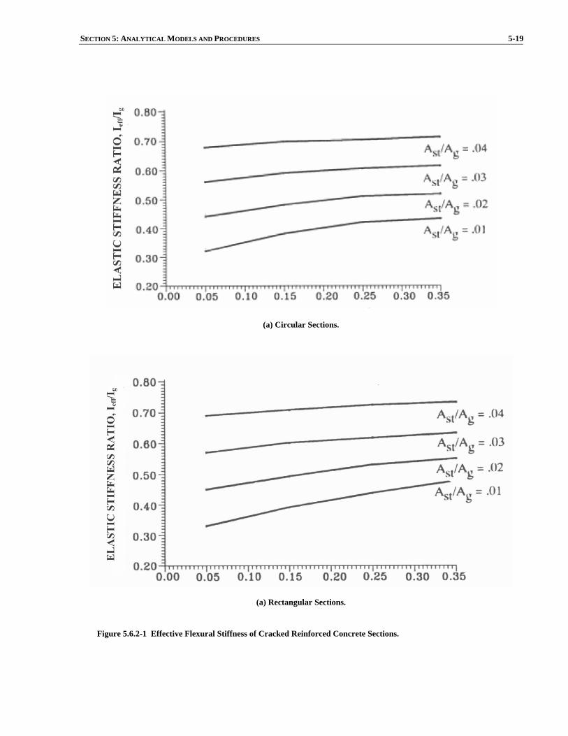
SECTION 5: ANALYTICAL MODELS AND PROCEDURES 5-19
(a) Circular Sections.
(a) Rectangular Sections.
Figure 5.6.2-1 Effective Flexural Stiffness of Cracked Reinforced Concrete Sections.

5-20 AASHTO GUIDE SPECIFICATIONS FOR LRFD SEISMIC BRIDGE DESIGN
y
yeffc
MIE
φ= (5.6.2-1)
where: My = moment capacity of section at first yield of the reinforcing steel (kip-in.) φy = curvature of section at first yield of the reinforcing steel including the effects of the unfactored axial dead load (1/in.) Ec = modulus of elasticity of concrete (ksi) Ieff = effective moment of inertia of the section based upon cracked concrete and first yield of the reinforcing steel (in.4)
The unfactored axial gravity load is typically usedwhen determining the effective properties.
The M-φ analysis parameters are defined in Articles8.4 and 8.5.
For pier walls in the strong direction, the shearstiffness parameter (GA)eff may be calculated as follows:
( )g
effewceff I
IAGGA = (5.6.2-2)
where: (GA)eff = effective shear stiffness parameter of the pier wall (kip) Gc = shear modulus of concrete (ksi) Aew = cross sectional area of pier wall (in.2) Ig = gross moment of inertia taken about the weak axis of the reinforced concrete cross section (in.4) Ieff = effective moment of inertia taken about the weak axis of the reinforced concrete cross section calculated from Eq. 1 or Figure 1 (in.4)
5.6.3 Ieff for Box Girder Superstructures
Ieff in box girder superstructures is dependent on theextent of cracking and the effect of the cracking on theelement’s stiffness.
Ieff for reinforced concrete box girder sections can beestimated between 0.5Ig and 0.75Ig. The lower boundrepresents lightly reinforced sections and the upper boundrepresents heavily reinforced sections.

SECTION 5: ANALYTICAL MODELS AND PROCEDURES 5-21
The location of the prestressing steel’s centroid andthe direction of bending have a significant impact on how cracking affects the stiffness of prestressed members.Multi-modal elastic analysis is incapable of capturing thevariations in stiffness caused by moment reversal. Therefore, no stiffness reduction is recommended forprestressed concrete box girder sections. 5.6.4 Ieff for Other Superstructure Types
Reductions to Ig similar to those specified for boxgirders can be used for other superstructure types and capbeams. A more refined estimate of Ieff based on M-φanalysis may be warranted for lightly reinforced girdersand precast elements.
5.6.5 Effective Torsional Moment of Inertia
A reduction of the torsional moment of inertia is notrequired for bridge superstructures. The torsional stiffnessof concrete members can be greatly reduced after the onsetof cracking. The torsional moment of inertia for columnsshall be reduced as follows:
geff JJ 2.0= (5.6.5-1) where: Jeff = effective torsional (polar) moment of inertia of reinforced concrete section (in.4) Jg = gross torsional (polar) moment of inertia of reinforced concrete section (in.4)


SECTION 6: FOUNDATION AND ABUTMENT DESIGN
TABLE OF CONTENTS
6-i
6.1 GENERAL.............................................................................................................................................................6-1 6.2 FOUNDATION INVESTIGATION......................................................................................................................6-1
6.2.1 Subsurface Investigation ..............................................................................................................................6-1 6.2.2 Laboratory Testing.......................................................................................................................................6-1 6.2.3 Foundation Investigation for SDC A ...........................................................................................................6-1 6.2.4 Foundation Investigation for SDC B and C .................................................................................................6-2 6.2.5 Foundation Investigation for SDC D ...........................................................................................................6-2
6.3 SPREAD FOOTINGS............................................................................................................................................6-2 6.3.1 General.........................................................................................................................................................6-2 6.3.2 Modeling of Footings...................................................................................................................................6-3 6.3.3 Spread Footings in Liquefiable Soils ...........................................................................................................6-3 6.3.4 Resistance to Overturning............................................................................................................................6-3 6.3.5 Resistance to Sliding....................................................................................................................................6-4 6.3.6 Flexure .........................................................................................................................................................6-4 6.3.7 Shear ............................................................................................................................................................6-5 6.3.8 Joint Shear ...................................................................................................................................................6-5 6.3.9 Foundation Rocking.....................................................................................................................................6-6
6.4 PILE CAP FOUNDATION ...................................................................................................................................6-6 6.4.1 General.........................................................................................................................................................6-6 6.4.2 Foundation with Standard Size Piles............................................................................................................6-6 6.4.3 Pile Foundations in Soft Soil .......................................................................................................................6-9 6.4.4 Other Pile Requirements ..............................................................................................................................6-9 6.4.5 Footing Joint Shear SDC C and D .............................................................................................................6-10 6.4.6 Effective Footing Width ............................................................................................................................6-12
6.5 DRILLED SHAFTS.............................................................................................................................................6-12 6.6 PILE EXTENSIONS............................................................................................................................................6-13 6.7 ABUTMENT DESIGN REQUIREMENTS ........................................................................................................6-13
6.7.1 Longitudinal Direction Requirements ........................................................................................................6-14 6.7.2 Transverse Direction Requirements ...........................................................................................................6-15 6.7.3 Other Requirements for Abutments ...........................................................................................................6-15
6.8 LIQUEFACTION DESIGN REQUIREMENTS .................................................................................................6-15

SECTION 6
FOUNDATION AND ABUTMENT DESIGN
6-1
6.1 GENERAL
This section includes only those foundation and
abutment requirements that are specifically related toseismic resistant construction. It assumes compliance withall the basic requirements necessary to provide support forvertical loads and lateral loads other than those due toearthquake motions. These include, but are not limited to,provisions for the extent of foundation investigation, fills, slope stability, bearing and lateral soil pressures, drainage,settlement control, and pile requirements and capacities.
6.2 FOUNDATION INVESTIGATION
6.2.1 Subsurface Investigation
Conduct subsurface investigations, including borings
and laboratory soil tests, to provide pertinent and sufficientinformation for the determination of the Site Class ofArticle 3.4.2.1. The type and cost of the foundationsshould be considered in the economic, environmental, andaesthetic studies for location and bridge type selection.
A subsurface investigation shall be conducted inaccordance with Article 10.4.2 of the AASHTO LRFD Bridge Design Specifications to provide pertinent andsufficient information for the determination of the SiteClass according to Article 3.4.2.1. In order to provide the input and site characterization needed to complete allgeotechnical aspects of the seismic design, laboratory and in-situ testing of the subsurface materials shall beconducted in accordance with Articles 10.4.3, 10.4.4, and10.4.5 of the AASHTO LRFD Bridge DesignSpecifications.
If the subsurface investigation indicates there is the potential for significant lateral spreading due toliquefaction at a bridge site located in SDC B or C, theowner may require that the structure design meet therequirements of SDC D.
C6.2.1 The goal of the site characterization for seismic design
is to develop the subsurface profile and soil property information required for seismic analyses. Soil parameters generally required for seismic design include:
• Initial dynamic shear modulus at small strains or
shear wave velocity,
• Equivalent viscous damping ratio,
• Shear modulus reduction and equivalent viscous damping characteristics as a function of shear strain,
• Cyclic shear strength parameters (peak and residual), and
• Liquefaction resistance parameters.
6.2.2 Laboratory Testing
Laboratory tests shall be performed to determine thestrength, deformation, and flow characteristics of soil androck or both, and their suitability for the foundation selected. In areas of higher seismicity (e.g., SDC D), itmay be appropriate to conduct special dynamic or cyclictests to establish the liquefaction potential or stiffness andmaterial damping properties of the soil at some sites, if unusual soils exist or if the foundation is supporting anessential or critical bridge.
6.2.3 Foundation Investigation for SDC A
There are no special seismic foundation investigationrequirements for SDC A.
6-2 AASHTO GUIDE SPECIFICATIONS FOR LRFD SEISMIC BRIDGE DESIGN
6.2.4 Foundation Investigation for SDC B and C
In addition to the normal site investigation, the
Engineer may require the submission of a report whichdescribes the results of an investigation to determinepotential hazards and seismic design requirements relatedto (1) slope instability, and (2) increases in lateral earthpressure, all as a result of earthquake motions. Seismicallyinduced slope instability in approach fills or cuts maydisplace abutments and lead to significant differentialsettlement and structural damage.
6.2.5 Foundation Investigation for SDC D
The Engineer may require the submission of a written
report, which shall include in addition to the potential hazard requirements of Article 6.2.4, a determination ofthe potential for surface rupture due to faulting ordifferential ground displacement (lurching), a site specificstudy to investigate the potential hazards of liquefactionand fill settlement in addition to the influence of cyclicloading on the deformation and strength characteristics offoundation soils.
Fill settlement and abutment displacements due tolateral pressure increases may lead to bridge accessproblems and structural damage. Liquefaction of saturatedcohesionless fills or foundation soils may contribute toslope and abutment instability, and could lead to a loss offoundation-bearing capacity and lateral pile support.Potential progressive degradation in the stiffness andstrength characteristics of saturated sands and soft claysshould be given particular attention. More detailed analyses of slope and abutment settlement duringearthquake loading should be undertaken.
6.3 SPREAD FOOTINGS 6.3.1 General
Spread footings in SDC B shall be proportioned toresist overturning, sliding, flexure, and shear due to thelesser of the following:
• The forces obtained from an elastic linear seismic
analysis.
• The forces associated with the overstrengthplastic moment capacity of the column or wall.
Spread footings in SDC C and SDC D shall beproportioned to resist overturning, sliding, flexure, andshear due to the forces associated with the overstrengthplastic moment capacity of the column or wall.
C6.3.1
In lower seismic hazard areas, seismic demands may not govern the design forces acting on the substructure. These specifications do not require that the forces associated with the overstrength plastic moment capacity of the column or wall be used to proportion footings in SDC B. However, since the columns in SDC B are designed and detailed to accommodate a displacement ductility demand of 2, designing the footings to accommodate the forces associated with the overstrength plastic moment capacity may be warranted.

SECTION 6: FOUNDATION AND ABUTMENT DESIGN 6-3 6.3.2 Modeling of Footings
Spread footing foundations shall be modeledaccording to Article 5.3.2.
Footings satisfying the requirements of Eq. 1 may beassumed to behave as rigid members. Footings that do notsatisfy Eq. 1 require additional analysis and are notconsidered in these specifications.
5.22
≤−
f
c
HDL
(6.3.2-1)
where: L = length of footing measured in the direction of
loading (ft.) Dc = column diameter or depth in direction of loading
(ft.) Hf = depth of footing (ft.)
C6.3.2
The lateral, vertical and rotational stiffness of spread footings shall be included in the bridge model.
6.3.3 Spread Footings in Liquefiable Soils
Spread footings shall not be located in soils that aresusceptible to liquefaction unless it is mitigated by groundimprovement.
C6.3.3
Spread footings founded in liquefiable soils are susceptible to large, unpredictable displacements and have resulted in bridge failures.
Soil densification has been used as a means of addressing liquefiable soils and may be appropriate for some locations.
6.3.4 Resistance to Overturning
The overturning demand due to forces associated withthe plastic overstrength moment of a column or wall shallbe less than the overturning resistance of the footing.Overturning shall be examined in each principal directionand satisfy the following requirement:
⎟⎠⎞
⎜⎝⎛ −
φ≤+2
aLPHVM ufpopo (6.3.4-1)
in which:
BqP
an
u= (6.3.4-2)
where: Mpo = overstrength plastic moment capacity of the
column calculated in accordance with Article 8.5(kip-ft.)
Vpo = overstrength plastic shear demand (kip) Hf = depth of footing (ft.)
C6.3.4
Eq. 1 neglects the lateral soil resistance that may develop along the depth of the footing. The omission of passive soil resistance along the depth of the footing is conservative, and in most cases, is insignificant. When the edge of the footing is cast against rock, Eq. 1 may be modified to incorporate the lateral rock resistance.

6-4 AASHTO GUIDE SPECIFICATIONS FOR LRFD SEISMIC BRIDGE DESIGN
Pu = axial force in column including the axial force
associated with overstrength plastic hingingcalculated in accordance with Article 4.11 (kip)
L = length of footing measured in the direction of
loading (ft.) B = width of footing measured normal to the direction
of loading (ft.) qn = nominal bearing capacity of supporting soil or
rock (ksf) φ = resistance factor for overturning of footing taken
as 0.7 6.3.5 Resistance to Sliding
The lateral demand due to the plastic overstrengthshear of the column shall be less than the sliding resistanceof the footing. Sliding shall be examined in each principaldirection and satisfy the following requirement:
npo RV φ≤ (6.3.5-1)
where: Vpo = overstrength plastic shear demand of the column
or wall (kip) φ = resistance factor for sliding of footing Rn = nominal sliding resistance against failure by
sliding determined in accordance with Article10.6.3.4 of the AASHTO LRFD Bridge DesignSpecifications (kip)
C6.3.5
Failure against sliding is addressed in Section 10 of the AASHTO LRFD Bridge Design Specifications.
6.3.6 Flexure
Flexural demands shall be investigated at the face of acolumn or wall for both positive and negative flexure andsatisfy the following:
un MM ≤φ (6.3.6-1)
where: Mu = factored ultimate moment demand in footing at
the face of the column or wall (kip-ft.) φ = resistance factor for concrete in bending Mn = nominal moment capacity of the footing at the
critical section including the effects ofreinforcing bars that are not fully developed atthe critical section (kip-ft.)
C6.3.6
The factored ultimate moment demand, Mu, should be based upon the actual soil pressure distribution resulting from the plastic overstrength moment of the column and the associated forces. The resulting soil pressure distribution may be linear or non-linear depending upon the magnitude of the demand as well as the nominal compressive resistance of the soil. In lieu of the actual soil pressure distribution under the footing, the moment associated with a fully plastic soil pressure distribution may be conservatively assumed in which case Mu would be determined as:
⎟⎠
⎞⎜⎝
⎛ −−=
2c
uuDaL
PM (C6.3.6-1)
in which:

SECTION 6: FOUNDATION AND ABUTMENT DESIGN 6-5
The effective width of the footing, beff, used to
calculate the nominal moment capacity of the footing, Mn, shall be taken as:
BHBb fceff ≤+= 2 (6.3.6-2)
where: Bc = diameter or width of column or wall measured
normal to the direction of loading (ft.) Hf = depth of footing (ft.) B = width of footing measured normal to the direction
of loading (ft.)
BqP
an
u= (C6.3.6-2)
where: Pu = factored ultimate axial force in column including
the axial force associated with overstrength plastic hinging calculated in accordance with Article 4.11 (kip)
L = length of footing measured in the direction of
loading (ft.) Dc = column diameter or depth in direction of loading
(ft.)
Shear lag effects in the footing render the reinforcement at the edges of the footing less effective in resisting flexural demands.
Caltrans Seismic Design Criteria permits the use of the full footing width, beff = B, when calculating the nominal moment and shear capacity of the footing provided that the requirements of Article 6.3.2 and Article 6.3.8 are satisfied.
6.3.7 Shear
Shear demands shall be investigated at the face of thecolumn or wall for both positive and negative bending and satisfy the following:
uns VV ≤φ (6.3.7-1)
where: Vu = factored ultimate shear demand in footing at the
face of the column or wall (kip) φs = 0.85 resistance factor for concrete in shear Vn = nominal shear capacity of the footing at the face
of the column calculated in accordance withArticle 5.8 of the AASHTO LRFD Bridge DesignSpecifications (kip)
The effective width of the footing, beff, used to
calculate the nominal shear capacity of the footing, Vn, shall be taken as that specified in Eq. 6.3.6-2.
C6.3.7
It is recommended that the minimum amount of shear reinforcement be provided in all footings that are subjected to the overstrength plastic moment capacity of the column. Shear reinforcement in footings is typically provided by “J” bars or headed bars.
6.3.8 Joint Shear
Joint shear shall satisfy the requirements of Article6.4.5.
C6.3.8
Column-footing joints are required to be designed to transfer the overstrength column forces to the footing.
6-6 AASHTO GUIDE SPECIFICATIONS FOR LRFD SEISMIC BRIDGE DESIGN
6.3.9 Foundation Rocking
Footings that do not satisfy the requirements of Eq.6.3.4-1 are subjected to rocking. Foundation rocking maybe used as an effective means of accommodating seismicdemands in a manner similar to isolation bearings. Withthe owner’s approval, foundation rocking may be used toaccommodate seismic demands (See Appendix A).
When rocking is considered as an ERE, the impactson system behavior shall be considered. Global (i.e. fullbridge or frame system) dynamic effects of rocking,whether by individual piers or more, shall be considered.Geotechnical capacities of the foundations, includingassessment of potential settlement, shall be undertaken toensure that undesirable system deformations do notjeopardize the resistance or stability of the bridge system(ERS).
C6.3.9
Research is ongoing on foundation rocking. At this time, the state of the practice does not warrant the utilization of foundation rocking for typical highway bridge structures.
6.4 PILE CAP FOUNDATION 6.4.1 General
The design of pile foundation for SDC B shall be
based on forces determined by capacity design principles or elastic seismic forces, whichever is smaller.
The design of pile foundation for SDC C or D shall bebased on forces determined by capacity design principles.
C6.4.1 To meet uplift loading requirements during a seismic
event, the depth of penetration may have to be greater than minimum requirements for compressive loading to mobilize sufficient uplift resistance. This uplift requirement can impose difficult installation conditions at locations where very hard bearing layers occur close to the ground surface. Ground anchors, insert piles, and H-pile stingers may be used in these locations to provide extra uplift resistance in these situations.
If batter piles are used in SDC D, consideration shouldbe given to (1) downdrag forces caused by dissipation of pore water pressures following liquefaction, (2) potential for lateral displacement of the soil from liquefaction-induced flow or lateral spreading, (3) ductility at the connection of the pile to the pile cap, and (4) buckling of the pile under combined horizontal and vertical loading. As such, use of batter piles should be handled on a case-by-case basis. Close interaction between the geotechnical engineer and the structural engineer will be essential when modeling the response of the batter pile for seismic loading.
For drained loading conditions, the vertical effective stress, σ'v, is related to the groundwater level and thus affects pile capacity. Seismic design loads have a low probability of occurrence. This low probability normally justifies not using the highest groundwater level during seismic design.
6.4.2 Foundation with Standard Size Piles
Standard size piles are considered to have a nominal
dimension less than or equal to 18 in. The provisions described below apply for columns
with monolithic fixed connections to the footings designedfor elastic forces as in SDC B or for column plastic hingeformation at the base as in SDC B, C, or D. For
C6.4.2 Capacity Protection for the foundation design is not
required for SDC B.
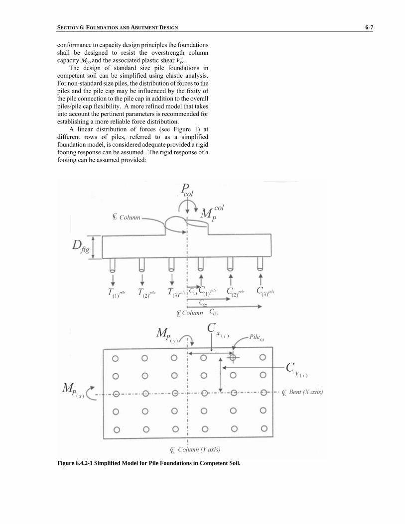
SECTION 6: FOUNDATION AND ABUTMENT DESIGN 6-7 conformance to capacity design principles the foundationsshall be designed to resist the overstrength columncapacity Mpo and the associated plastic shear Vpo.
The design of standard size pile foundations incompetent soil can be simplified using elastic analysis. For non-standard size piles, the distribution of forces to thepiles and the pile cap may be influenced by the fixity ofthe pile connection to the pile cap in addition to the overallpiles/pile cap flexibility. A more refined model that takesinto account the pertinent parameters is recommended for establishing a more reliable force distribution.
A linear distribution of forces (see Figure 1) at different rows of piles, referred to as a simplifiedfoundation model, is considered adequate provided a rigidfooting response can be assumed. The rigid response of a footing can be assumed provided:
Figure 6.4.2-1 Simplified Model for Pile Foundations in Competent Soil.

6-8 AASHTO GUIDE SPECIFICATIONS FOR LRFD SEISMIC BRIDGE DESIGN
5.2≤ftg
ftg
DL
(6.4.2-1)
where: Lftg = cantilever overhang length measured from
the face of wall or column to the outside edge ofthe pile cap or footing (ft.)
Dftg = depth of the pile cap or footing (ft.)
Pile groups designed with the simplified foundation model can be sized to resist the plastic moment of thecolumn Mp in lieu of Mpo defined in Article 8.5.
For conforming to capacity design principles, thedistribution of forces on these piles shall be examined about the x and y axis in addition to the diagonal directionof the foundation cap considering that the principal axes of the column correspond to x and y axis. For cases wherethe column principal axes do not correspond to pile capaxes, the number of iterations shall be enough to ensurehinging in the column.
For SDC C and D, the axial demand on an individualpile shall be taken as:
)(
)()(
)(
)()(
)(
)(
xpg
iycol
xP
ypg
ixcol
yP
ppilei
pilei
IcM
IcM
N
PTC
±±=⎪⎭
⎪⎬⎫ ∑ (6.4.2-2)
in which:
∑=
=yN
iixxypg cnI
1
2)()( (6.4.2-3)
∑=
=xN
iiyyxpg cnI
1
2)()( (6.4.2-4)
where: Ipg(y) = effective moment of inertia of pile group about the “y” axis (pile-ft.2) Ipg(x) = effective moment of inertia of pile group
about the “x” axis (pile-ft.2)
colxpM )( = the component of the column overstrength
plastic hinging moment capacity about the “x” axis (kip-ft.)
colypM )( = the component of the column overstrength
plastic hinging moment capacity about the “y” axis (kip-ft.)
Np = total number of piles in the pile group (pile)

SECTION 6: FOUNDATION AND ABUTMENT DESIGN 6-9 nx = number of piles in a single parallel to the “x”
axis ny = number of piles in a single row parallel to the
“y” axis ∑P = total unfactored axial load due to dead load,
earthquake load, footing weight, soil overburden and all other vertical demands acting on the pile group (kip)
cx(i) = distance from neutral axis of pile group to
“ith” row of piles measured parallel to the “x” axis (ft.)
cy(i) = distance from neutral axis of pile group to
“ith” row of piles measured parallel to the “y” axis (ft.)
pileiC )( = compression force in “ith” pile (kip)
pileiT )( = tension force in “ith” pile (kip)
For SDC B, where elastic forces control, the axial
demand on an individual pile shall be determinedaccording to Eq. 2 with the elastic forces and momentsaccording to Article 4.4 substituted for the overstrengthforces and moments.
6.4.3 Pile Foundations in Soft Soil
In soft soils the pile cap may not dominate the lateral
stiffness of the foundation, as is expected in competentsoil, possibly leading to significant lateral displacements.The designer shall verify that the pile cap structuralcapacity exceeds the lateral demand transmitted by thecolumns, and the piles. In soft soils, piles shall bedesigned and detailed to accommodate imposeddisplacements and axial forces based on analyticalfindings.
6.4.4 Other Pile Requirements
Piles may be used to resist both axial and lateral loads.
The minimum depth of embedment, together with the axial and lateral pile capacities, required to resist seismicloads shall be determined by means of the design criteriaestablished in the site investigation report. Groupreduction factors established in the geotechnical reportshould be included in the analysis and design of pilesrequired to resist lateral loads. The ultimate geotechnicalcapacity of the piles should be used in designing for seismic loads.
When reliable uplift pile capacity from skin-friction is
C6.4.4
Friction piles may be considered to have uplift resistance due to skin friction, or, alternately, 50 percent of the ultimate compressive axial load capacity may be assumed for uplift capacity. Uplift capacity need not be taken as less than the weight of the pile (buoyancy considered).
6-10 AASHTO GUIDE SPECIFICATIONS FOR LRFD SEISMIC BRIDGE DESIGN
present, the pile to footing connection detail is present, andthe pile to footing connection detail and structural capacityof the pile are adequate, uplift of a pile footing isacceptable, provided that the magnitude of footing rotationwill not result in unacceptable performance according toP-∆ requirements stated in Article 4.11.5.
All concrete piles shall be reinforced to resist thedesign moments, shears, and axial loads. Minimum reinforcement shall be in accordance with Article 8.16.
Footings shall be proportioned to provide the required minimum embedment, clearance and spacing, requirementsaccording to the provisions of the AASHTO LRFD Bridge Design Specifications. The spacing shall be increased when required by subsurface conditions. For SDC D,embedment of pile reinforcement in the footing cap shallbe in accordance with Article 8.8.4. 6.4.5 Footing Joint Shear SDC C and D
All footing to column moment resistive joints in SDC
C and D shall be proportioned such that the principalstresses meet the following criteria: Principal compression:
'25.0 cc fp ≤ (6.4.5-1) Principal tension:
'38.0 ct fp ≤ (6.4.5-2) in which:
22
22 jvvv
t vff
p +⎟⎟⎠
⎞⎜⎜⎝
⎛−= (6.4.5-3)
22
22 jvvv
c vff
p +⎟⎠
⎞⎜⎝
⎛+= (6.4.5-4)
and:
ftg
ftgeff
jvjv DB
Tv = (6.4.5-5)
in which: ∑−= pile
icjv TTT )( (6.4.5-6) ftg
effB = effective width of footing (in.)
= cjD2 for circular columns (6.4.5-7)

SECTION 6: FOUNDATION AND ABUTMENT DESIGN 6-11 = cjc DB + for rectangular columns (6.4.5-8) and:
ftgjh
colv A
Pf = (6.4.5-9)
in which: ftg
jhA = effective horizontal area at mid-depth of the footing assuming a 45o spread away
from the boundary of the column in all directions as shown in Figure 1 (in.2) = 2)( ftgcj DD + for circular columns (6.4.5-10)
= ⎟⎟⎠
⎞⎜⎜⎝
⎛+⎟⎟
⎠
⎞⎜⎜⎝
⎛+
22ftg
cjftg
c
DD
DB
for rectangular columns (6.4.5-11) where: Dcj = column width or diameter parallel to the direction of bending (in.) Bc = diameter or width of column or wall measured normal to the direction of loading (ft.) Dftg = depth of footing (in.) Pcol = column axial force including the effects of overturning (kip)
'cf = uniaxial compressive concrete strength (ksi)
Tc = column tensile force associated with the
column overstrength plastic hinging moment, Mpo (kip)
∑ pile
iT )( = summation of the hold down force in the tension piles (kip)
Transverse joint reinforcement shall be provided inaccordance with Article 8.8.8.

6-12 AASHTO GUIDE SPECIFICATIONS FOR LRFD SEISMIC BRIDGE DESIGN
beff
b eff P col
f v
Dftg45
b eff
beff
45
M o
Dc
Dc
Bc
Figure 6.4.5-1 Effective Joint Width for Footing Joint Shear Stress. 6.4.6 Effective Footing Width
For footings in SDC C and D exhibiting rigidresponse and satisfying joint shear criteria, the entire widthof the footing may be considered effective in resisting thecolumn overstrength flexure and the associated shear.
6.5 DRILLED SHAFTS
Design requirements of drilled shafts shall conform to requirements of columns in SDC B, C, or D as applicable.
The effects of degradation and aggredation in astreambed on fixity and plastic hinge locations shall beconsidered for SDC B, C, and D.
The effects of liquefaction on loss of P-y strengthshall be considered for SDC D.
A stable length shall be ensured for a singlecolumn/shaft. The stable length shall be determined inaccordance with Article 10.7.3.12 of the AASHTO LRFD Bridge Design Specifications, except that a load factor of1.0 should be applied to the calculated lateral loads for thefoundation. Overstrength properties may be used for thefoundation and column elements.
The ultimate geotechnical capacity of singlecolumn/shaft foundation in compression and uplift shallnot be exceeded under maximum seismic loads.
C6.5 Various studies (Lam et al., 1998) have found that
conventional P-y stiffnesses derived for driven piles are too soft for drilled shafts. This stiffer response is attributed to a combination of (1) higher unit side friction, (2) base shear at the bottom of the shaft, and (3) the rotation of the shaft. The rotation effect is often implicitly included in the interpretation of lateral load tests, as most lateral load tests are conducted in a free-head condition. A scaling factor equal to the ratio of shaft diameter to 2 ft. is generally applicable, according to Lam et al. (1998). The scaling factor is applied to either the linear subgrade modulus or the resistance value in the P-y curves. This adjustment is dependent on the construction method.
Base shear can also provide significant resistance to lateral loading for large diameter shafts. The amount of resistance developed in shear will be determined by conditions at the base of the shaft during construction. For dry conditions where the native soil is relatively undisturbed, the contributions for base shear can be significant. However, in many cases the base conditions result in low interface strengths. For this reason the amount of base shear to incorporate in lateral analyses will vary from case to case.
Lam et al. (1998) provides a detailed discussion of the seismic response and design of drilled shaft foundations. Their discussion includes a summary of procedures to determine the stiffness matrix required to represent the
SECTION 6: FOUNDATION AND ABUTMENT DESIGN 6-13
shaft foundation in most dynamic analyses. Drilled shaft foundations will often involve a single
shaft, rather than a group of shafts. This is not the case for driven piles. In single shaft configuration the relative importance of axial and lateral response changes. Withoutthe equivalent of a pile cap, lateral-load displacement of the shaft becomes more critical than the load-displacement relationships discussed above for driven piles.
The depth for stable conditions will depend on the stiffness of the rock or soil. Lower stable lengths are acceptable if the embedment length and the strength of drilled shaft provide sufficient lateral stiffness with adequate allowances for uncertainties in soil stiffness. In Caltrans practice, a stability factor of 1.2 is applied to single-column bents supported on a pile shaft.
Section properties of drilled shaft should be consistent with the deformation caused by the seismic loading. In many cases it is necessary to use the cracked section modulus in the evaluation of lateral load-displacement relationships. In the absence of detailed information regarding reinforcing steel and applied load, an equivalent cracked section can be estimated by reducing the stiffness of the uncracked section by half. In general the cracked section is function of the reinforcement ratio and axial load, but it often adequate to assume as one-half of the uncracked section.
6.6 PILE EXTENSIONS
Design requirements of pile extensions shall conform
to requirements of columns in SDC B, C, or D asapplicable.
The effects of degradation and aggredation in astreambed on fixity and plastic hinges locations shall beconsidered in SDC B, C, and D.
The effects of liquefaction on loss of P-y strength shall be considered in SDC D. Group reduction factorsshall be included in the analysis and design of pileextensions subjected to lateral loading in the transversedirection.
6.7 ABUTMENT DESIGN REQUIREMENTS
The participation of abutment walls in the overall
dynamic response of bridge systems to earthquake loadingand in providing resistance to seismically induced inertialloads shall be considered in the seismic design of bridgesin accordance with Article 5.2.
Abutment design shall be consistent with the demandmodel consistent with the ERS used to assess intermediatesubstructure elements.
For conventional cantilever retaining wallconstruction, horizontal wall translation under dynamic active pressure loading is acceptable. However, rotationalinstability may lead to collapse and thus shall be prevented.
6-14 AASHTO GUIDE SPECIFICATIONS FOR LRFD SEISMIC BRIDGE DESIGN
6.7.1 Longitudinal Direction Requirements The seismic design of free-standing abutments should
take into account forces arising from seismically-induced lateral earth pressures, additional forces arising from wallinertia effects and the transfer of seismic forces from thebridge deck through bearing supports which do not slidefreely (e.g., elastomeric bearings).
For free-standing abutments or retaining walls whichmay displace horizontally without significant restraint(e.g., superstructure supported by sliding bearings), thedesign approach is similar to that of a free-standingretaining wall, except that longitudinal force from thebridge superstructure needs to be included in equilibriumevaluations, as the superstructure moves outwards from thewall.
Earthquake-induced active earth pressures should becomputed using horizontal accelerations at least equal to50% of the peak site ground acceleration (i.e., FaSs / 5.0). The pseudostatic Mononobe-Okabe method of analysis isrecommended for computing lateral active soil pressuresduring seismic loading. The effects of vertical accelerationmay be omitted.
Abutment displacements having a maximum drift of4% may be tolerated. A limiting equilibrium conditionshould be checked in the horizontal direction. If necessary, wall design (initially based on a static service loadingcondition) should be modified to meet the above condition.
For monolithic abutments where the abutment formsan integral part of the bridge superstructure, the abutmentshall be designed using one of the two alternatives depending on the contribution level accounted for in theanalytical model:
• At a minimum, the abutment shall be designed to
resist the passive pressure applied by theabutment backfill.
• If the abutment is part of the ERS and required tomobilize the full active pressure, a reduction factor greater than or equal to 0.5 shall be appliedto the design forces provided a brittle failure doesnot exist in the load path transmitted to thesuperstructure.
For free-standing abutments which are restrained fromhorizontal displacement by anchors or concrete batterpiles, earthquake-induced active earth pressures should becomputed using horizontal accelerations at least equal tothe site peak ground acceleration (i.e., FaSs / 2.5), as a firstapproximation. The Mononobe-Okabe analysis method isrecommended using the above mentioned horizontalacceleration. Up to 50% reduction in the horizontalacceleration can be used provided the various components of the restrained wall can accommodate the increased levelof displacement demand.
C6.7.1 These Guide Specifications have been prepared to
acknowledge the abutment to be used as an Earthquake Resistant Element (ERE) and be a part of the Earthquake Resistant System (ERS). If designed properly, the reactive capacity of the approach fill can provide significant benefit to the bridge-foundation system.
SECTION 6: FOUNDATION AND ABUTMENT DESIGN 6-15 6.7.2 Transverse Direction Requirements
The provisions outlined in Article 5.2.4 shall be
followed depending on the mechanism of transfer of superstructure transverse inertial forces to the bridgeabutments and following the abutment contribution to the Earthquake Resisting System (ERS) applicable for SDC Cand D.
6.7.3 Other Requirements for Abutments
For SDC D, abutment pile foundation design may be
governed by liquefaction design requirements as outlinedin Article 6.8.
To minimize potential loss of bridge access arising from abutment damage, monolithic or end diaphragmconstruction is strongly recommended for bridges less than500 ft.
Settlement or approach slabs providing structural support between approach fills and abutments shall beprovided for all bridges in SDC D. Slabs shall beadequately linked to abutments using flexible ties.
For SDC D, the abutment skew should be minimized. Bridges with skewed abutments above 20° have a tendency for increased displacements at the acute corner. In the case where a large skew can not be avoided, sufficient seatwidth in conjunction with an adequate shear key shall bedesigned to ensure against any possible unseating of thebridge superstructure.
6.8 LIQUEFACTION DESIGN REQUIREMENTS
Liquefaction assessment is required for a bridge inSDC D.
If it is determined that liquefaction can occur at abridge site then the bridge shall be supported on deepfoundations or the ground improved so that liquefaction does not occur. For liquefied sites subject to lateral flow,the Engineer shall consider the use of large diameter shaftsin lieu of the conventional pile cap foundation type inorder to minimize lateral flow demands on the bridgefoundation. If liquefaction occurs then the bridge shall bedesigned and analyzed in two configurations as follows:
• Non-Liquefied Configuration. The structure shall
be analyzed and designed, assuming noliquefaction occurs using the ground response spectrum appropriate for the site soil conditions.
• Liquefaction Configuration. The structure asdesigned in non-liquefied configuration aboveshall be reanalyzed and redesigned, if necessary, assuming that the layer has liquefied and theliquefied soil provides the appropriate residual resistance (i.e., P-y curves or modulus of sub-grade reaction values for lateral pile response analyses consistent with liquefied soilconditions). The design spectra shall be the same
C6.8 Liquefaction below a spread footing foundation can
result in three conditions that lead to damage or failure of a bridge:
• Loss in bearing support which causes large
vertical downward movement,
• Horizontal forces on the footing from lateral flow or lateral spreading of the soil, and
• Settlements of the soil as pore water pressures in the liquefied layers dissipate.
Most liquefaction-related damage during pastearthquakes has been related to lateral flow or spreading of the soil. In these cases ground movements could be 3 ft. or more. If the spread footing foundation is located above the water table, as is often the case, it will be very difficult to prevent the footing from being displaced with the moving ground. This could result in severe column distortion and eventual loss of supporting capacity.
In some underwater locations, it is possible that the lateral flow could move past the footing without causing excessive loading; however, these cases will be limited.
If liquefaction with no lateral flow occurs for SDC D bridges, then the only additional design requirements are
6-16 AASHTO GUIDE SPECIFICATIONS FOR LRFD SEISMIC BRIDGE DESIGN
as that used in non-liquefied configuration unlessa site-specific response spectra has beendeveloped using nonlinear, effective stressmethods that properly account for the buildup inpore-water pressure and stiffness degradation inliquefiable layers. The reduced response spectraresulting from the site-specific nonlinear,effective stress analyses shall not be less than 2/3of that used in the non-liquefied configuration.
The Designer shall cover explicit detailing of plastichinging zones for both cases mentioned above since it islikely that locations of plastic hinges for the LiquefiedConfiguration are different than locations of plastic hingesfor the Non-Liquefied Configuration. Design requirementsof SDC D including shear reinforcement shall be met forthe liquefied and non-liquefied configuration.
those reinforcement requirements specified for the piles. Additional analyses are not required, although for essential or critical bridges additional analyses may be considered in order to assess the impact on the substructures above the foundation.
If liquefaction and lateral flow are predicted to occur for SDC D, a detailed evaluation of the effects of lateral flow on the foundation should be performed. Lateral flow is one of the more difficult issues to address because of the uncertainty in the movements that may occur.
Ultimate plastic rotation of the piles is permitted. This plastic rotation does imply that the piles and possibly other parts of the bridge will need to be replaced if these levels of deformation do occur. Design options range from (a) an acceptance of the movements with significant damage to the piles and columns if the movements are large, to (b) designing the piles to resist the forces generated by lateral spreading. Between these options are a range of mitigation measures to limit the amount of movement to tolerable levels for the desired performance objective. Pile group effects are not significant for liquefied soil.

SECTION 7: STRUCTURAL STEEL COMPONENTS
TABLE OF CONTENTS
7-i
7.1 GENERAL.............................................................................................................................................................7-1 7.2 PERFORMANCE CRITERIA...............................................................................................................................7-4
7.2.1 Type 1 ..........................................................................................................................................................7-4 7.2.2 Type 2 ..........................................................................................................................................................7-4 7.2.3 Type 3 ..........................................................................................................................................................7-5
7.3 MATERIALS.........................................................................................................................................................7-6 7.4 MEMBER REQUIREMENTS FOR SDC C AND D ............................................................................................7-7
7.4.1 Limiting Slenderness Ratios ........................................................................................................................7-7 7.4.2 Limiting Width-Thickness Ratios ................................................................................................................7-7 7.4.3 Flexural Ductility for Members with Combined Flexural and Axial Load ................................................7-11 7.4.4 Combined Axial and Bending....................................................................................................................7-11 7.4.5 Weld Locations ..........................................................................................................................................7-12 7.4.6 Ductile End Diaphragm in Slab-on-Girder Bridge.....................................................................................7-12 7.4.7 Shear Connectors .......................................................................................................................................7-13
7.5 DUCTILE MOMENT RESISTING FRAMES AND SINGLE COLUMN STRUCTURES FOR SDC C AND D ...........................................................................................................................................................7-14
7.5.1 Columns.....................................................................................................................................................7-14 7.5.2 Beams ........................................................................................................................................................7-15 7.5.3 Panel Zones and Connections ....................................................................................................................7-16 7.5.4 Multi-Tier Frame Bents .............................................................................................................................7-16
7.6 CONCRETE FILLED STEEL PIPES FOR SDC C AND D ............................................................................... 7-17 7.6.1 Combined Axial Compression and Flexure ...............................................................................................7-19 7.6.2 Flexural Strength........................................................................................................................................7-19 7.6.3 Beams and Connections .............................................................................................................................7-21
7.7 CONNECTIONS FOR SDC C AND D...............................................................................................................7-21 7.7.1 Minimum Strength for Connections to Ductile Members ..........................................................................7-21 7.7.2 Yielding of Gross Section for Connections to Ductile Members ...............................................................7-22 7.7.3 Welded Connections ..................................................................................................................................7-22 7.7.4 Gusset Plate Strength .................................................................................................................................7-22 7.7.5 Limiting Unsupported Edge Length to Thickness Ratio for a Gusset Plate ...............................................7-22 7.7.6 Gusset Plate Tension Strength ...................................................................................................................7-23 7.7.7 Compression Strength of a Gusset Plate ....................................................................................................7-24 7.7.8 In-Plane Moment (Strong Axis).................................................................................................................7-24 7.7.9 In-Plane Shear Strength .............................................................................................................................7-24 7.7.10 Combined Moment, Shear, and Axial Forces ..........................................................................................7-24 7.7.11 Fastener Capacity.....................................................................................................................................7-25
7.8 ISOLATION DEVICES.......................................................................................................................................7-26 7.9 FIXED AND EXPANSION BEARINGS............................................................................................................7-26
7.9.1 Applicability ..............................................................................................................................................7-26 7.9.2 Design Criteria...........................................................................................................................................7-26 7.9.3 Design and Detail Requirements................................................................................................................7-27 7.9.4 Bearing Anchorage ....................................................................................................................................7-27
7.10 STRUCTURAL STEEL DESIGN REQUIREMENTS FOR ENERGY DISIPATION COMPONENTS IN SDC C AND D ......................................................................................................................................................7-28
7.10.1 General.....................................................................................................................................................7-28

SECTION 7
STRUCTURAL STEEL COMPONENTS
7-1
7.1 GENERAL
The Engineer shall demonstrate that a clear,
straightforward load path (see Figure 1) within the superstructure, through the bearings or connections to thesubstructure, within the substructure, and ultimately to thefoundation exists. All components and connections shallbe capable of resisting the imposed seismic load effectsconsistent with the chosen load path.
The flow of forces in the prescribed load path shall beaccommodated through all affected components and their connections including, but not limited to, flanges and websof main beams or girders, cross-frames, steel-to-steel connections, slab-to-steel interfaces, and all components ofthe bearing assembly from bottom flange interface through the anchorage of anchor bolts or similar devices in thesubstructure. The substructure shall also be designed totransmit the imposed force effects into the soils beneaththe foundations.
The analysis and design of end diaphragms and cross-frames shall include the horizontal supports at anappropriate number of bearings, consistent with Article 7.8and Article 7.9.
The following requirements apply to bridges witheither:
• a concrete deck that can provide horizontal
diaphragm action or
• a horizontal bracing system in the plane of thetop flange, which in effect provides diaphragmaction.
A load path (see Figure 1) shall be established totransmit the inertial loads to the foundation based on thestiffness characteristics of the deck, diaphragms, cross-frames, and lateral bracing. Unless a more refined analysis is made, an approximate load path shall be assumed asfollows:
• The seismic inertia loads in the deck shall be
assumed to be transmitted directly to the bearingsthrough end diaphragms or cross-frames.
• The development and analysis of the load paththrough the deck or through the top lateral bracing, if present, shall utilize assumedstructural actions analogous to those used for theanalysis of wind loadings.
Reference to AASHTO LRFD Bridge Design Specifications is based on the 2007 Fourth Edition withsubsequent updates pertinent to the articles mentioned inthis document.
C7.1 Most components of steel bridges are not expected to
behave in a cyclic inelastic manner during an earthquake.The provisions of this article are only applicable to thelimited number of components (such as specially detailedductile substructures or ductile diaphragms) whose stablehysteretic behavior is relied upon to ensure satisfactorybridge seismic performance. The seismic provisions of thisarticle are not applicable to the other steel membersexpected to remain elastic during seismic response. Inmost steel bridges, the steel superstructure is expected (orcan be designed) to remain elastic.
One span of the San Francisco-Oakland Bay Bridgecollapsed due to loss of support at its bearings during the1989 Loma Prieta earthquake, and another bridge sufferedsevere bearing damage (EERI, 1990). The end diaphragmsof some steel bridges suffered damage in a subsequentearthquake in northern California (Roberts, 1992). Duringthe 1994 Northridge earthquake some steel bridges,located close to the epicenter, sustained damage to eithertheir reinforced concrete abutments, connections betweenconcrete substructures and steel superstructures, steeldiaphragms or structural components near the diaphragms(Astaneh-Asl et al., 1994). Furthermore, a large number ofsteel bridges were damaged by the 1995 Hyogoken-Nanbu(Kobe) earthquake. The concentration of steel bridges inthe area of severe ground motion was considerably largerthan for any previous earthquake and some steel bridgescollapsed. Many steel piers, bearings, seismic restrainersand superstructure components suffered significantdamage (Bruneau, Wilson and Tremblay, 1996). Thisexperience emphasizes the importance of ductile detailingin the critical elements of steel bridges.
Research on the seismic behavior of steel bridges (e.g.Astaneh-Asl, Shen and Cho, 1993; Dicleli and Bruneau,1995a, 1995b; Dietrich and Itani, 1999; Itani et al., 1998a;McCallen and Astaneh-Asl, 1996; Seim, Ingham andRodriguez, 1993; Uang et al., 2000; Uang et al., 2001;Zahrai and Bruneau 1998) and findings from recentseismic evaluation and rehabilitation projects (e.g. Astanehand Roberts, 1996; Ballard et al., 1996; Billings et al,1996; Dameron et al., 1995; Donikian et al., 1996; Gates etal., 1995; Imbsen et al., 1997; Ingham et al., 1996; Jones etal., 1997; Kompfner et al., 1996; Maroney 1996; Prucz etal., 1997; Rodriguez and Inghma, 1996; Schamber et al.,1997; Shirolé and Malik, 1993; Vincent et al., 1997)further confirm that seismically induced damage is likelyin steel bridges subjected to large earthquakes and thatappropriate measures shall be taken to ensure satisfactoryseismic performance.
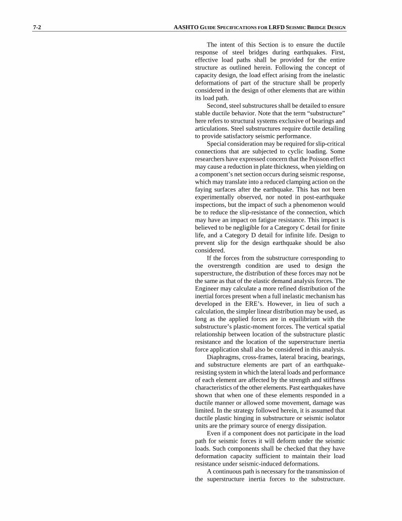
7-2 AASHTO GUIDE SPECIFICATIONS FOR LRFD SEISMIC BRIDGE DESIGN The intent of this Section is to ensure the ductile
response of steel bridges during earthquakes. First,effective load paths shall be provided for the entirestructure as outlined herein. Following the concept ofcapacity design, the load effect arising from the inelasticdeformations of part of the structure shall be properlyconsidered in the design of other elements that are withinits load path.
Second, steel substructures shall be detailed to ensurestable ductile behavior. Note that the term “substructure”here refers to structural systems exclusive of bearings andarticulations. Steel substructures require ductile detailingto provide satisfactory seismic performance.
Special consideration may be required for slip-criticalconnections that are subjected to cyclic loading. Someresearchers have expressed concern that the Poisson effectmay cause a reduction in plate thickness, when yielding ona component’s net section occurs during seismic response,which may translate into a reduced clamping action on thefaying surfaces after the earthquake. This has not beenexperimentally observed, nor noted in post-earthquakeinspections, but the impact of such a phenomenon wouldbe to reduce the slip-resistance of the connection, whichmay have an impact on fatigue resistance. This impact isbelieved to be negligible for a Category C detail for finitelife, and a Category D detail for infinite life. Design toprevent slip for the design earthquake should be alsoconsidered.
If the forces from the substructure corresponding tothe overstrength condition are used to design thesuperstructure, the distribution of these forces may not bethe same as that of the elastic demand analysis forces. TheEngineer may calculate a more refined distribution of theinertial forces present when a full inelastic mechanism hasdeveloped in the ERE’s. However, in lieu of such acalculation, the simpler linear distribution may be used, aslong as the applied forces are in equilibrium with thesubstructure’s plastic-moment forces. The vertical spatialrelationship between location of the substructure plasticresistance and the location of the superstructure inertiaforce application shall also be considered in this analysis.
Diaphragms, cross-frames, lateral bracing, bearings,and substructure elements are part of an earthquake-resisting system in which the lateral loads and performanceof each element are affected by the strength and stiffnesscharacteristics of the other elements. Past earthquakes haveshown that when one of these elements responded in aductile manner or allowed some movement, damage waslimited. In the strategy followed herein, it is assumed thatductile plastic hinging in substructure or seismic isolatorunits are the primary source of energy dissipation.
Even if a component does not participate in the loadpath for seismic forces it will deform under the seismicloads. Such components shall be checked that they havedeformation capacity sufficient to maintain their loadresistance under seismic-induced deformations.
A continuous path is necessary for the transmission ofthe superstructure inertia forces to the substructure.
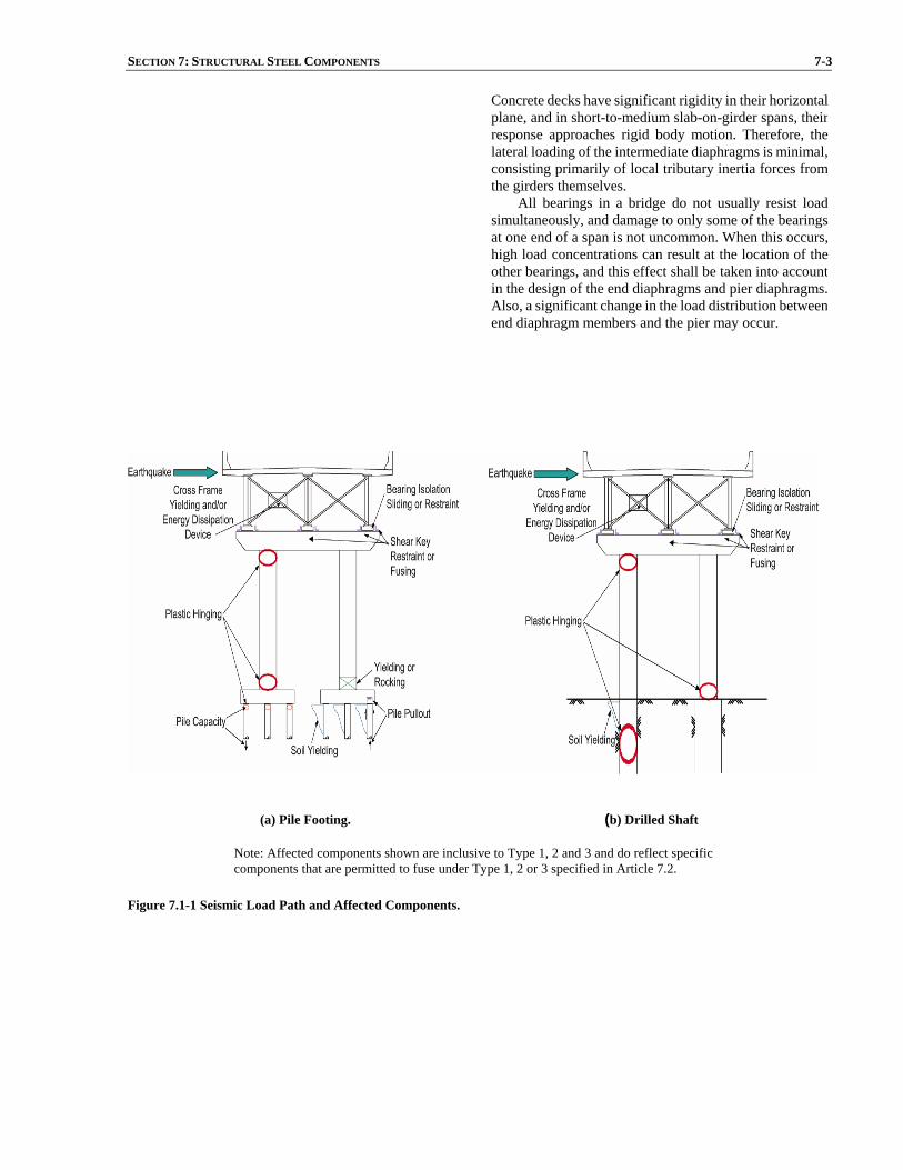
SECTION 7: STRUCTURAL STEEL COMPONENTS 7-3
Concrete decks have significant rigidity in their horizontalplane, and in short-to-medium slab-on-girder spans, theirresponse approaches rigid body motion. Therefore, thelateral loading of the intermediate diaphragms is minimal,consisting primarily of local tributary inertia forces fromthe girders themselves.
All bearings in a bridge do not usually resist loadsimultaneously, and damage to only some of the bearingsat one end of a span is not uncommon. When this occurs,high load concentrations can result at the location of theother bearings, and this effect shall be taken into accountin the design of the end diaphragms and pier diaphragms.Also, a significant change in the load distribution betweenend diaphragm members and the pier may occur.
(a) Pile Footing. (b) Drilled Shaft
Note: Affected components shown are inclusive to Type 1, 2 and 3 and do reflect specific components that are permitted to fuse under Type 1, 2 or 3 specified in Article 7.2.
Figure 7.1-1 Seismic Load Path and Affected Components.
7-4 AASHTO GUIDE SPECIFICATIONS FOR LRFD SEISMIC BRIDGE DESIGN 7.2 PERFORMANCE CRITERIA
This section is intended for design of superstructure
steel components. Those components are classified intotwo categories: Ductile and Essentially Elastic. Based onthe characteristics of the bridge structure, the designer hasone of three options for a seismic design strategy:
• Type 1 - Design a ductile substructure with an
essentially elastic superstructure.
• Type 2 - Design an essentially elastic sub-structure with a ductile superstructure.
• Type 3 - Design an elastic superstructure andsubstructure with a fusing mechanism at theinterface between the superstructure and thesubstructure.
In this section, reference to an essentially elasticcomponent is used where the force demand to the nominalcapacity ratio of any member in the superstructure is lessthan 1.5.
Seismic design forces for individual members andconnections of bridges identified as Type 2 are determinedby dividing the unreduced elastic forces by the appropriateResponse Modification Factor (R) as specified in Article 7.2.2. These factors shall only be used when all of thedesign requirements of this Section are satisfied. Acombination of orthogonal seismic forces equivalent to theorthogonal seismic displacement combination specified inArticle 4.4 shall be used to obtain the unreduced elasticforces.
C7.2 The design of ductile steel structural response is based
primarily upon a forced-based, not displacement-based,seismic design approach. The provisions in this section areto be used in conjunction with the forced-based seismicdesign procedure utilized in the AASHTO LRFD BridgeDesign Specifications.
7.2.1 Type 1
For Type 1 structures, the designer shall refer to
Section 8 or Article 7.5 of this document on designing fora ductile substructure as applicable to SDC C and D.
7.2.2 Type 2
For Type 2 structures, the design of the superstructure
is accomplished using a force-based approach with anappropriate reduction for ductility. Those factors are usedfor the design of transverse bracing members, top lateralsand bottom laterals. For SDC B, C, or D a reduction factor,R, equal to 3 is used for ordinary bracing that is a part ofthe Earthquake Resistant System (ERS) not having ductileend-diaphragms as defined in Article 7.4.6. The forcereduction factor, R, can be increased to 4 for SDC D if the provisions in Article 7.4.6 are satisfied.
For simply supported spans with special end-diaphragms in compliance with Article 7.4.6, the locationof the diaphragms shall, as a minimum, be placed at theends of each span.
For continuous spans where these special diaphragms
SECTION 7: STRUCTURAL STEEL COMPONENTS 7-5
are used, the location of diaphragms shall, as a minimum,be placed over each bent and one cross-frame spacing adjacent to the opposite faces of the bent. The use ofspecial diaphragms at opposite faces of an in-span hinge should be carefully assessed to ensure adequate verticalload capacity of the in-span hinge when subjected todeformations in the inelastic range.
For SDC B, C, or D a single angle bracing can be usedfor the diagonal member of the end-cross-frame. As this practice is typical and favored for ease of construction, thedesign process for a single angle bracing shall follow AISC stand-alone document on LRFD Design Specification for Single-Angle Members.
For SDC D, double angles with stitch welds can beused as members of the end diaphragm ERS. Members with stitch welds shall follow the design process includedin the AISC LRFD Specifications Chapter E on compactand non-compact prismatic members subject to axialcompression through the centroidal axis.
7.2.3 Type 3
For Type 3 structures, the designer shall assess the
overstrength capacity for the fusing interface including shear keys and bearings, then design for an essentiallyelastic superstructure and substructure. The minimumlateral design force shall be calculated using anacceleration of 0.4 g or the elastic seismic force whicheveris smaller. If isolation devices are used, the superstructureshall be designed as essentially elastic (see Article 7.8).
Other framing systems and frames that incorporate special bracing, active control, or other energy absorbingdevices, or other types of special ductile superstructureelements shall be designed on the basis of published research results, observed performance in past earthquakes, or special investigation, and provide a level of safety comparable to those in the AASHTO LRFD Bridge Design Specifications.
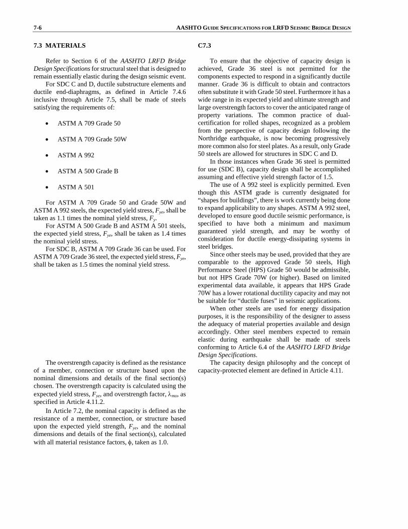
7-6 AASHTO GUIDE SPECIFICATIONS FOR LRFD SEISMIC BRIDGE DESIGN 7.3 MATERIALS
Refer to Section 6 of the AASHTO LRFD Bridge
Design Specifications for structural steel that is designed toremain essentially elastic during the design seismic event.
For SDC C and D, ductile substructure elements andductile end-diaphragms, as defined in Article 7.4.6 inclusive through Article 7.5, shall be made of steelssatisfying the requirements of:
• ASTM A 709 Grade 50
• ASTM A 709 Grade 50W
• ASTM A 992
• ASTM A 500 Grade B
• ASTM A 501
For ASTM A 709 Grade 50 and Grade 50W and
ASTM A 992 steels, the expected yield stress, Fye, shall betaken as 1.1 times the nominal yield stress, Fy.
For ASTM A 500 Grade B and ASTM A 501 steels,the expected yield stress, Fye, shall be taken as 1.4 timesthe nominal yield stress.
For SDC B, ASTM A 709 Grade 36 can be used. ForASTM A 709 Grade 36 steel, the expected yield stress, Fye, shall be taken as 1.5 times the nominal yield stress.
C7.3 To ensure that the objective of capacity design is
achieved, Grade 36 steel is not permitted for thecomponents expected to respond in a significantly ductilemanner. Grade 36 is difficult to obtain and contractorsoften substitute it with Grade 50 steel. Furthermore it has awide range in its expected yield and ultimate strength andlarge overstrength factors to cover the anticipated range ofproperty variations. The common practice of dual-certification for rolled shapes, recognized as a problemfrom the perspective of capacity design following theNorthridge earthquake, is now becoming progressivelymore common also for steel plates. As a result, only Grade50 steels are allowed for structures in SDC C and D.
In those instances when Grade 36 steel is permittedfor use (SDC B), capacity design shall be accomplishedassuming and effective yield strength factor of 1.5.
The use of A 992 steel is explicitly permitted. Eventhough this ASTM grade is currently designated for“shapes for buildings”, there is work currently being doneto expand applicability to any shapes. ASTM A 992 steel,developed to ensure good ductile seismic performance, isspecified to have both a minimum and maximumguaranteed yield strength, and may be worthy ofconsideration for ductile energy-dissipating systems insteel bridges.
Since other steels may be used, provided that they arecomparable to the approved Grade 50 steels, HighPerformance Steel (HPS) Grade 50 would be admissible,but not HPS Grade 70W (or higher). Based on limitedexperimental data available, it appears that HPS Grade70W has a lower rotational ductility capacity and may notbe suitable for “ductile fuses” in seismic applications.
When other steels are used for energy dissipationpurposes, it is the responsibility of the designer to assessthe adequacy of material properties available and designaccordingly. Other steel members expected to remainelastic during earthquake shall be made of steelsconforming to Article 6.4 of the AASHTO LRFD BridgeDesign Specifications.
The overstrength capacity is defined as the resistanceof a member, connection or structure based upon thenominal dimensions and details of the final section(s)chosen. The overstrength capacity is calculated using theexpected yield stress, Fye, and overstrength factor, λmo, as specified in Article 4.11.2.
The capacity design philosophy and the concept ofcapacity-protected element are defined in Article 4.11.
In Article 7.2, the nominal capacity is defined as theresistance of a member, connection, or structure basedupon the expected yield strength, Fye, and the nominaldimensions and details of the final section(s), calculatedwith all material resistance factors, φ, taken as 1.0.
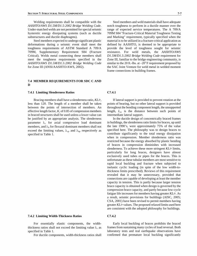
SECTION 7: STRUCTURAL STEEL COMPONENTS 7-7
Welding requirements shall be compatible with theAASHTO/AWS D1.5M/D1.5:2002 Bridge Welding Code. Under-matched welds are not permitted for special seismichysteretic energy dissipating systems (such as ductilesubstructures and ductile diaphragms).
Steel members expected to undergo significant plasticdeformations during a seismic event shall meet the toughness requirements of ASTM Standard A 709/A709M, Supplementary Requirement S84 (FractureCritical). Welds metal connecting these members shallmeet the toughness requirements specified in theAASHTO/AWS D1.5M/D1.5:2002 Bridge Welding Codefor Zone III (ANSI/AASHTO/AWS, 2002).
Steel members and weld materials shall have adequatenotch toughness to perform in a ductile manner over therange of expected service temperatures. The A 709/A709M S84 "Fracture-Critical Material Toughness Testingand Marking" requirement, typically specified when thematerial is to be utilized in a fracture-critical application asdefined by AASHTO, is deemed to be appropriate toprovide the level of toughness sought for seismicresistance. For weld metals, the AASHTO/AWSD1.5M/D1.5:2002 Bridge Welding Code requirement forZone III, familiar to the bridge engineering community, issimilar to the 20 ft.-lbs. at –20o F requirement proposed bythe SAC Joint Venture for weld metal in welded momentframe connections in building frames.
7.4 MEMBER REQUIREMENTS FOR SDC C AND D
7.4.1 Limiting Slenderness Ratios
Bracing members shall have a slenderness ratio, KL/r, less than 120. The length of a member shall be takenbetween the points of intersection of members. An effective length factor, K, of 0.85 of compression membersin braced structures shall be used unless a lower value canbe justified by an appropriate analysis. The slendernessparameter λc for axial compressive load dominantmembers, and λb for flexural dominant members shall notexceed the limiting values, λcp and λbp respectively as specified in Table 1.
C7.4.1
If lateral support is provided to prevent rotation at thepoints of bearing, but no other lateral support is providedthroughout the bending component length, the unsupportedlength, Lu, is the distance between such points ofintermediate lateral support.
In the ductile design of concentrically braced framesin buildings, the slenderness ratio limits for braces, up untilthe late 1990’s, were approximately 75% of the valuespecified here. The philosophy was to design braces tocontribute significantly to the total energy dissipationwhen in compression. Member slenderness ratio wasrestricted because the energy absorbed by plastic bendingof braces in compression diminishes with increasedslenderness. To achieve these more stringent KL/r limits,particularly for long braces, designers have almostexclusively used tubes or pipes for the braces. This isunfortunate as these tubular members are most sensitive torapid local buckling and fracture when subjected toinelastic cyclic loading (in spite of the low width-to-thickness limits prescribed). Reviews of this requirementrevealed that it may be unnecessary, provided thatconnections are capable of developing at least the membercapacity in tension. This is partly because larger tensionbrace capacity is obtained when design is governed by thecompression brace capacity, and partly because low-cyclefatigue life increases for members having greater KL/r. Asa result, seismic provisions for buildings (AISC, 2005;CSA, 2001) have been revised to permit members havinggreater KL/r values. The proposed relaxed limits used hereare consistent with the adopted philosophy for buildings.
7.4.2 Limiting Width-Thickness Ratios
For essentially elastic components, the width-
thickness ratios shall not exceed the limiting value λr as specified in Table 1.
For ductile components, width-thickness ratios shall
C7.4.2 Early local buckling of braces prohibits the braced
frames from sustaining many cycles of load reversal. Bothlaboratory tests and real earthquake observations haveconfirmed that premature local buckling significantly
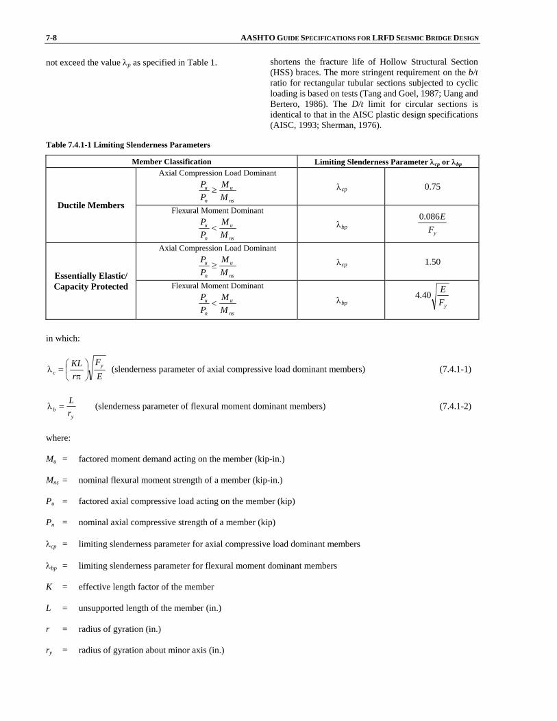
7-8 AASHTO GUIDE SPECIFICATIONS FOR LRFD SEISMIC BRIDGE DESIGN not exceed the value λp as specified in Table 1. shortens the fracture life of Hollow Structural Section
(HSS) braces. The more stringent requirement on the b/tratio for rectangular tubular sections subjected to cyclicloading is based on tests (Tang and Goel, 1987; Uang andBertero, 1986). The D/t limit for circular sections isidentical to that in the AISC plastic design specifications(AISC, 1993; Sherman, 1976).
Table 7.4.1-1 Limiting Slenderness Parameters
in which:
EF
rKL y
c ⎟⎠⎞
⎜⎝⎛
π=λ (slenderness parameter of axial compressive load dominant members) (7.4.1-1)
yb r
L=λ (slenderness parameter of flexural moment dominant members) (7.4.1-2)
where: Mu = factored moment demand acting on the member (kip-in.) Mns = nominal flexural moment strength of a member (kip-in.) Pu = factored axial compressive load acting on the member (kip) Pn = nominal axial compressive strength of a member (kip) λcp = limiting slenderness parameter for axial compressive load dominant members λbp = limiting slenderness parameter for flexural moment dominant members K = effective length factor of the member L = unsupported length of the member (in.) r = radius of gyration (in.) ry = radius of gyration about minor axis (in.)
Member Classification Limiting Slenderness Parameter λcp or λbp Axial Compression Load Dominant
ns
u
n
u
MM
PP
≥ λcp 0.75
Ductile Members Flexural Moment Dominant
ns
u
n
u
MM
PP
< λbp yF
E086.0
Axial Compression Load Dominant
ns
u
n
u
MM
PP
≥ λcp 1.50 Essentially Elastic/ Capacity Protected Flexural Moment Dominant
ns
u
n
u
MM
PP
< λbp yFE40.4

SECTION 7: STRUCTURAL STEEL COMPONENTS 7-9
Fy = specified minimum yield strength of steel (ksi) E = modulus of elasticity of steel (ksi)
The remainder of this page is left intentionally blank.
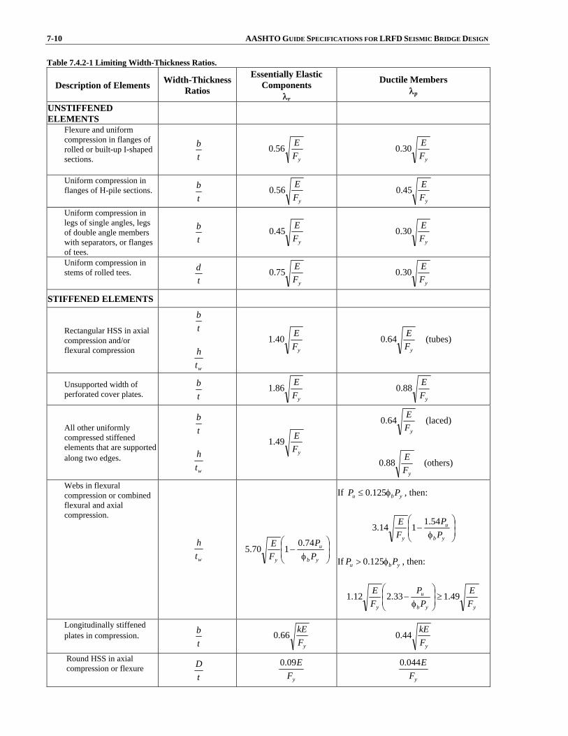
7-10 AASHTO GUIDE SPECIFICATIONS FOR LRFD SEISMIC BRIDGE DESIGN Table 7.4.2-1 Limiting Width-Thickness Ratios.
Description of Elements Width-Thickness Ratios
Essentially Elastic Components
λr
Ductile Members λp
UNSTIFFENED ELEMENTS
Flexure and uniform compression in flanges of rolled or built-up I-shaped sections.
tb
yFE56.0
yFE30.0
Uniform compression in flanges of H-pile sections.
tb
yFE56.0
yFE45.0
Uniform compression in legs of single angles, legs of double angle members with separators, or flanges of tees.
tb
yFE45.0
yFE30.0
Uniform compression in stems of rolled tees.
td
yFE75.0
yFE30.0
STIFFENED ELEMENTS
Rectangular HSS in axial compression and/or flexural compression
tb
wth
yFE40.1
yFE64.0 (tubes)
Unsupported width of perforated cover plates. t
b yF
E86.1 yF
E88.0
All other uniformly compressed stiffened elements that are supported along two edges.
tb
wth
yFE49.1
yFE64.0 (laced)
yFE88.0 (others)
Webs in flexural compression or combined flexural and axial compression.
wth ⎟
⎟⎠
⎞⎜⎜⎝
⎛
φ−
yb
u
y PP
FE 74.0
170.5
If ybu PP φ≤ 125.0 , then:
⎟⎟⎠
⎞⎜⎜⎝
⎛
φ−
yb
u
y PP
FE 54.1114.3
If ybu PP φ> 125.0 , then:
yyb
u
y FE
PP
FE 49.133.212.1 ≥⎟
⎟⎠
⎞⎜⎜⎝
⎛
φ−
Longitudinally stiffened plates in compression.
tb
yFkE66.0
yFkE44.0
Round HSS in axial compression or flexure
tD
yFE09.0
yFE044.0

SECTION 7: STRUCTURAL STEEL COMPONENTS 7-11
in which: If n = 1, then:
48 3/1
3 ≤⎟⎠
⎞⎜⎝
⎛=btIk s (7.4.2-1)
If n = 2, 3, 4, or 5, then:
43.14 3/1
43 ≤⎟⎠
⎞⎜⎝
⎛=nbtIk s (7.4.2-2)
where: k = plate buckling coefficient for uniform normal stress n = number of equally spaced longitudinal compression flange stiffeners Is = moment of inertia of a single longitudinal stiffener about an axis parallel to the flange and taken at the base of the
stiffener (in.4) φb = 0.9 resistance factor for flexure Fy = specified minimum yield strength of steel (ksi) E = modulus of elasticity of steel (ksi) b = width of unstiffened element (in.) d = overall depth of section (in.) D = diameter of HSS tube (in.) t = thickness of unstiffened element, plate thickness, or HSS wall thickness (in.) tw = thickness of web plate (in.) h = web depth (in.) Pu = factored axial load acting on the member (kip) Py = nominal axial yield strength of a member (kip) 7.4.3 Flexural Ductility for Members with Combined Flexural and Axial Load
Ductility in bending can be utilized only if axial loads
are less than 60% of the nominal yield strength of member.Demand-to-capacity ratios or displacement ductilities shallbe kept less than unity if the axial load coinciding with themoment is greater than 60% of the nominal yield strength of the member
7.4.4 Combined Axial and Bending
Members under combined axial and bending
interaction shall be checked using interaction equations

7-12 AASHTO GUIDE SPECIFICATIONS FOR LRFD SEISMIC BRIDGE DESIGN following AASHTO LRFD Bridge Design Specifications. 7.4.5 Weld Locations
Welds that are located in the expected inelastic regionof ductile components shall be made complete jointpenetration welds. Partial joint penetration groove weldsare not permitted in the expected inelastic regions. Splicesare not permitted in the inelastic region of ductilecomponents.
7.4.6 Ductile End Diaphragm in Slab-on-Girder Bridge
Ductile end-diaphragms in slab-on-girder bridges can
be designed to be the ductile energy dissipating elementsfor seismic excitations in the transverse directions of straight bridges provided that:
• Specially detailed diaphragms, which are capable
of dissipating energy in a stable manner withoutstrength degradation, can be used. The diaphragmbehavior shall be verified by cyclic testing.
• Only ductile energy dissipating systems withadequate seismic performance that has beenproven through cyclic inelastic testing are used.
• Design considers the combined relative stiffnessand strength of end-diaphragms and girders(including bearing stiffeners) in establishing the diaphragms strength and design forces toconsider for the capacity protected elements.
• The response modification factor, R, to beconsidered in design of the ductile diaphragm isgiven by:
⎟⎟⎟⎟
⎠
⎞
⎜⎜⎜⎜
⎝
⎛
+
+μ=
SUB
DED
SUB
DED
KKKK
R1
(7.4.6-1)
where: μ = displacement ductility capacity of the end diaphragm not to exceed 4 KDED = stiffness of the ductile end diaphragm (kip/in.) KSUB = stiffness of the substructure (kip/in.)
• All details/connections of the ductile end-diaphragms are welded.
• The bridge does not have horizontal wind-bracing
SECTION 7: STRUCTURAL STEEL COMPONENTS 7-13
connecting the bottom flanges of girders, unlessthe last wind bracing panel before each support isdesigned as a ductile panel equivalent and inparallel to its adjacent vertical end-diaphragm.
• An effective mechanism is present to ensuretransfer of the inertia-induced transversehorizontal seismic forces from the slab to thediaphragm.
Special design provisions for a Concentrically BracedFrame (CBF) or an Eccentrically Braced Frame (EBF),following the ANSI/AISC Seismic Provisions for StructuralSteel Buildings 2005, shall be used in addition torequirements stated in this document.
Overstrength factors to be used to design the capacity-protected elements depend on the type of ductilediaphragm used, and shall be supported by available experimental research results. 7.4.7 Shear Connectors
Shear connectors should be provided on the flanges of
girders, end cross frames or diaphragms to transfer seismicloads from the concrete deck to the abutments or pier supports in SDC A, B and C and shall be provided in SDCD.
For the transverse seismic load, the effective shearconnectors should be taken as those located on the flangesof girders, end cross frames or diaphragms that are nofurther than 9tw on each side of the outer projectingelements of the bearing stiffener group.
For the longitudinal seismic load, the effective shearconnectors should be taken as all those located on thegirder flange within the tributary span length of thesupport.
The seismic load at columns/piers should be thesmaller of the following:
• The overstrength shear of the columns/piers
• 1.3 times the capacity of the bracing systems ifthey are considered as ductile seismic resistingsystems
The seismic load at abutments should be the smaller of the following:
• The overstrength shear of the shear keys
• 1.3 times the capacity of the bracing systems ifthey are considered as ductile seismic resistingsystems
Nominal strength of the shear connectors shall be inaccordance with Article 6.10.10 of the AASHTO LRFD Bridge Design Specifications.
C7.4.7
These provisions are primarily from Caltrans Guide Specifications for Seismic Design of Steel Bridges(Caltrans 2001). The cross frames or diaphragms at the end of each span are the main components to transfer the lateral seismic loads from the deck down to the bearing locations. Tests on a 0.4 scale experimental steel girder bridge (60 ft. long) conducted by University of Nevada, Reno (Carden, et al. 2001) indicated that too few shear connectors between the girders and deck at the bridge end did not allow the end cross frame to reach its ultimate capacity. Supporting numerical analysis on a continuous multi-span bridge showed that for non-composite negative moment regions, the absence of shear connectors at the end of a bridge span caused large weak axis bending stresses in the girders likely to cause buckling or yielding of the girders before the capacity of the ductile component was reached. Furthermore there were large forces in the intermediate cross frames, therefore, the end cross frames were no longer the only main components transferring lateral seismic loads form the deck to the bearings. It is, therefore, recommended that adequate shear connectors be provided above supports to transfer seismic lateral loads. These shear connectors can be placed on the girders or the top struts of the end cross frame or diaphragms.
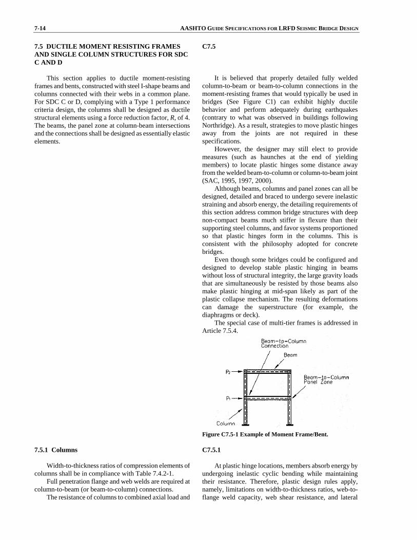
7-14 AASHTO GUIDE SPECIFICATIONS FOR LRFD SEISMIC BRIDGE DESIGN 7.5 DUCTILE MOMENT RESISTING FRAMES AND SINGLE COLUMN STRUCTURES FOR SDC C AND D
This section applies to ductile moment-resisting
frames and bents, constructed with steel I-shape beams andcolumns connected with their webs in a common plane.For SDC C or D, complying with a Type 1 performancecriteria design, the columns shall be designed as ductilestructural elements using a force reduction factor, R, of 4. The beams, the panel zone at column-beam intersectionsand the connections shall be designed as essentially elasticelements.
C7.5 It is believed that properly detailed fully welded
column-to-beam or beam-to-column connections in the moment-resisting frames that would typically be used in bridges (See Figure C1) can exhibit highly ductile behavior and perform adequately during earthquakes (contrary to what was observed in buildings following Northridge). As a result, strategies to move plastic hinges away from the joints are not required in these specifications.
However, the designer may still elect to provide measures (such as haunches at the end of yielding members) to locate plastic hinges some distance away from the welded beam-to-column or column-to-beam joint (SAC, 1995, 1997, 2000).
Although beams, columns and panel zones can all be designed, detailed and braced to undergo severe inelastic straining and absorb energy, the detailing requirements of this section address common bridge structures with deep non-compact beams much stiffer in flexure than their supporting steel columns, and favor systems proportioned so that plastic hinges form in the columns. This is consistent with the philosophy adopted for concrete bridges.
Even though some bridges could be configured and designed to develop stable plastic hinging in beams without loss of structural integrity, the large gravity loads that are simultaneously be resisted by those beams also make plastic hinging at mid-span likely as part of the plastic collapse mechanism. The resulting deformations can damage the superstructure (for example, the diaphragms or deck).
The special case of multi-tier frames is addressed in Article 7.5.4.
Figure C7.5-1 Example of Moment Frame/Bent.
7.5.1 Columns
Width-to-thickness ratios of compression elements of
columns shall be in compliance with Table 7.4.2-1. Full penetration flange and web welds are required at
column-to-beam (or beam-to-column) connections. The resistance of columns to combined axial load and
C7.5.1
At plastic hinge locations, members absorb energy by undergoing inelastic cyclic bending while maintaining their resistance. Therefore, plastic design rules apply, namely, limitations on width-to-thickness ratios, web-to-flange weld capacity, web shear resistance, and lateral
SECTION 7: STRUCTURAL STEEL COMPONENTS 7-15
flexure shall be determined in accordance with Article6.9.2.2 of the AASHTO LRFD Bridge DesignSpecifications. The factored axial compression due to seismic load and permanent loads shall not exceed0.20AgFy.
The shear resistance of the column web shall bedetermined in accordance with Article 6.10.9 of theAASHTO LRFD Bridge Design Specifications.
The potential plastic hinge regions (Article 4.11.8),near the top and base of each column, shall be laterallysupported and the unsupported distance (i.e., between theplastic hinges) from these locations shall not exceed thevalue determined from Table 7.4.1-1. The lateral supportsshall be provided either directly to the flanges or indirectlythrough a column web stiffener or a continuity plate. Eachcolumn flange lateral support shall resist a force of not lessthan 2% of the nominal column flange strength (0.02bf tfFy) at the support location. The possibility of complete load reversal shall be considered and the potential for plastic hinging about both principal axes of a column shallbe considered. The requirements for lateral supports do not apply to potential in-ground plastic hinging zones of pile bents
support. Axial load in columns is also restricted to avoid early
deterioration of beam-column flexural strengths andductility when subject to high axial loads. Tests by Popov et al. (1975) showed that W-shaped columns subjected to inelastic cyclic loading suffered sudden failure due to excessive local buckling and strength degradation when the maximum axial compressive load exceeded 0.50AgFy. Tests by Schneider et al. (1992) showed that moment-resisting steel frames with hinging columns suffer rapid strength and stiffness deterioration when the columns are subjected to compressive load equal to approximately 0.25AgFy. Most building codes set this limit at 0.30AgFy.
When lateral support cannot be provided, the columnmaximum slenderness, KL/r, shall not exceed 60 andtransverse moments produced by the forces otherwise resisted by the lateral bracing (including the second ordermoment due to the resulting column displacement) shall beincluded in the seismic load combinations.
Splices that incorporate partial joint penetration groove welds shall be located away from the plastic hingeregions as defined in Article 4.11.8 at a minimum distance equal to the greater of:
• One-fourth the clear height of column
• Twice the column depth
• 39 in.
The requirement for lateral support is similar to Eq. 6.10.8.2.3-1 of the AASHTO LRFD Bridge Design Specifications with a stress, f1, of zero (zero moment) at one end of the member, but modified to ensure inelastic rotation capacities of at least four times the elastic rotation corresponding to the plastic moment. Consideration of a null moment at one end of the column accounts for changes in location of the inflexion point of the column moment diagram during earthquake response. Figure 10.27 in Bruneau et al. (1997) could be used to develop other unsupported lengths limits.
Built-up columns made of fastened components (e.g., bolted or riveted) are beyond the scope of these Guidelines.
7.5.2 Beams
The factored resistance of the beams shall bedetermined in accordance with Article 6.12 of theAASHTO LRFD Bridge Design Specifications. At a joint between beams and columns the sum of the factoredresistances of the beams shall not be less than the sum ofthe probable resistances of the column(s) framing into thejoint. Unless otherwise demonstrated by rational analysis, the probable flexural resistance of columns, Mnx, shall be taken as the product of the overstrength factor times the columns nominal flexural resistance determined either inaccordance with Article 6.9.2.2 of the AASHTO LRFD Bridge Design Specifications or by:
pxye
upxnx M
AFPMM ≤⎟
⎟⎠
⎞⎜⎜⎝
⎛−= 118.1 (7.5.2-1)
C7.5.2 Since plastic hinges are not expected to form in
beams, beams need not conform to plastic design requirements.
The requirement for beam resistance is consistent with the outlined capacity-design philosophy. The beams shouldeither resist the full elastic loads or be capacity-protected. In the extreme load situation, the capacity-protected beams are required to have nominal resistances of not less than the combined effects corresponding to the plastic hinges in the columns attaining their probable capacity and the probable companion permanent load acting directly on the beams. The columns' probable capacity should account for the overstrength due to higher yield than specified yield and strain hardening effects. The value specified in Article 6.9.2.2 of the AASHTO LRFD Bridge Design Specifications, used in conjunction with the resistance
7-16 AASHTO GUIDE SPECIFICATIONS FOR LRFD SEISMIC BRIDGE DESIGN where: Mpx = plastic moment capacity of the member based
upon expected material properties (kip-ft.) A = cross sectional area of member (in.2) Fye = expected yield stress of structural steel member
(ksi) Pu = factored axial load acting on member (kip)
factor φf for steel beams in flexure of 1.00, is compatible with the AISC (2005) 1.1, Ry, used with a resistance factor φ of 0.9 (here Ry is embedded in Fye).
Eq. 1 was developed for I-sections about strong axis bending and may not be appropriate for other sections.
7.5.3 Panel Zones and Connections
Column-beam intersection panel zones, moment
resisting connections and column base connections shall bedesigned as Essentially Elastic Elements.
Panel zones shall be designed such that the vertical shearing resistance is determined in accordance withArticle 6.10.9 of the AASHTO LRFD Bridge DesignSpecifications.
Beam-to-column connections shall have resistance notless than the resistance of the beam stipulated in Article7.5.2.
Continuity plates shall be provided on both sides ofthe panel zone web and shall finish with total width of atleast 0.8 times the flange width of the opposing flanges.The continuity plate b/t ratio shall meet the limits for projecting elements of Article 6.9.4.2 of the AASHTOLRFD Bridge Design Specifications. The continuity platesshall be proportioned to meet the stiffener requirements stipulated in Article 6.10.11.2 of the AASHTO LRFD Bridge Design Specifications and shall be connected toboth flanges and the web.
Flanges and connection plates in bolted connections shall have a factored net section ultimate resistancecalculated by Eq. 6.8.2.1-2, at least equal to the factoredgross area yield resistance given by Eq. 6.8.2.1-1, with Agand An in Article 6.8.2.1 of the AASHTO LRFD BridgeDesign Specifications taken here as the area of the flangesand connection plates in tension.
C7.5.3 The panel zone should either resist the full elastic load
(i.e., R = 1.0) or be capacity-protected. Column base connections should also resist the full
elastic loads (R = 1.0) or be capacity-protected, unless they are designed and detailed to dissipate energy.
Panel zone yielding is not permitted. There is a concern that doubler plates in panel zones
can be an undesirable fatigue detail. For plate-girder sections, it is preferable to specify a thicker web plate, if necessary, rather than use panel zone doubler plates.
7.5.4 Multi-Tier Frame Bents
For multi-tier frame bents, capacity design principles
as well as the requirements of Articles 7.5.1, 7.5.2, and7.5.3 may be modified by the engineer to achieve columnplastic hinging only at the top of the column. Column plastic hinging at the base where fixity to the foundation isneeded shall be assessed where applicable.
C7.5.4 Multi-tier frame bents are sometimes used because
they are more rigid transversely than single-tier frame bents. In such multi-tier bents, the intermediate beams are significantly smaller than the top beam as they are not supporting the gravity loads from the superstructure.
As a result, in a multi-tier frame, plastic hinging in the beams may be unavoidable in all but the top beam. Trying to ensure strong-beam weak-column design at all joints in multi-tier bents may have the undesirable effect of concentrating all column plastic hinging in one tier, with greater local ductility demands than otherwise expected in design.
Using capacity design principles, the equations and

SECTION 7: STRUCTURAL STEEL COMPONENTS 7-17
intent of Article 7.5.1 and Article 7.5.2 may be modified by the designer to achieve column plastic hinging only at the top and base of the column, and plastic hinging at the ends of all intermediate beams, as shown in Figure C1.
Figure C7.5.4-1 Acceptable Plastic Mechanism for Multi-Tier Bent.
7.6 CONCRETE FILLED STEEL PIPES FOR SDC C AND D
Concrete-filled steel pipes used as columns, piers, or
piles expected to develop full plastic hinging of thecomposite section as a result of seismic response shall be designed in accordance with Articles 6.9.2.2, 6.9.5,6.12.3.2.2, of the AASHTO LRFD Bridge DesignSpecifications as well as the requirements in this article.
C7.6 This article is only applicable to concrete-filled steel
pipes without internal reinforcement, and connected in a way that allows development of their full composite strength. It is not applicable to design a concrete-filled steel pipe that relies on internal reinforcement to provide continuity with another structural element, or for which the steel pipe is not continuous or connected in a way that enables it to develop its full yield strength. When used in pile bent, the full composite strength of the plastic hinge located below ground can only be developed if it can be ensured that the concrete fill is present at that location.
Research (e.g., Alfawahkiri, 1997; Bruneau and Marson, 1999) demonstrates that the AASHTO equations for the design of concrete-filled steel pipes in combined axial compression and flexure (Articles 6.9.2.2, 6.9.5, and 6.12.2.3.2 of the AASHTO LRFD Bridge Design Specifications) provide a conservative assessment of beam-column strength. Consequently, the calculated strength of concrete-filled steel pipes that could be used as columns in ductile moment-resisting frames or pile-bents could be significantly underestimated. This is not surprising given that these equations together are deemed applicable to a broad range of composite member types and shapes, including concrete-encased steel shapes.
While these equations may be perceived as conservative from a non-seismic perspective, an equation that more realistically captures the plastic moment of suchcolumns is essential for capacity design. Capacity-protected elements shall be designed with adequate strength to elastically withstand the plastic hinging in the columns. Underestimating the plastic hinging force translate into under-design of the capacity-protected

7-18 AASHTO GUIDE SPECIFICATIONS FOR LRFD SEISMIC BRIDGE DESIGN
elements. A column unknowingly stronger than expected will not hinge prior to damaging foundations or other undesirable locations in the structure. This can have severe consequences, as the capacity-protected elements are not detailed to withstand large inelastic deformations. The provisions of Article 7.3 are added to prevent this behavior.
For analysis, the flexural stiffness of the composite concrete filled pipe section may be taken as given in Eq. C1 which is a modified form of that given in Article 5.7.4.3 of the AASHTO LRFD Bridge Design Specifications.
5.2)( cc
sseffIEIEEI += (C7.6-1)
where: Ic = moment of inertia of the concrete core (in.4) Is = moment of inertia of the steel pipe (in.4) Es = modulus of elasticity of steel (ksi) Ec = modulus of elasticity of concrete (ksi)
Alternatively, the flexural stiffness of the composite concrete filled pipe section may be taken as given in Eq. C2 which is a modified form of that given in Article 6.9.5.1 of the AASHTO LRFD Bridge Design Specifications.
sss
csseff IE
AA
nIEEI ≥⎟⎟
⎠
⎞⎜⎜⎝
⎛+=
352.088.0)( (C7.6-2)
where: Ac = area of the concrete core (in.2) As = area of the steel pipe (in.2) Is = moment of inertia of the steel pipe (in.4) n = modular ratio
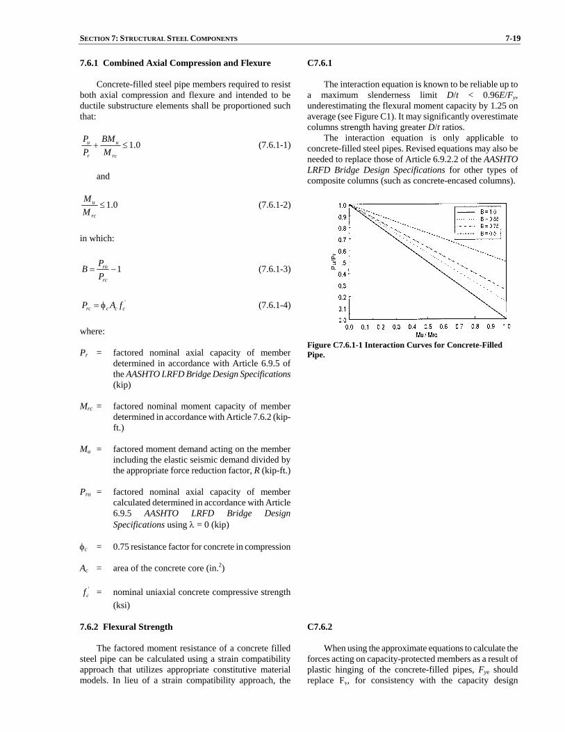
SECTION 7: STRUCTURAL STEEL COMPONENTS 7-19
7.6.1 Combined Axial Compression and Flexure Concrete-filled steel pipe members required to resist
both axial compression and flexure and intended to be ductile substructure elements shall be proportioned suchthat:
0.1≤+rc
u
r
u
MBM
PP (7.6.1-1)
and
0.1≤rc
u
MM (7.6.1-2)
in which:
1−=rc
ro
PPB (7.6.1-3)
'
cccrc fAP φ= (7.6.1-4) where: Pr = factored nominal axial capacity of member
determined in accordance with Article 6.9.5 ofthe AASHTO LRFD Bridge Design Specifications(kip)
Mrc = factored nominal moment capacity of member
determined in accordance with Article 7.6.2 (kip-ft.)
Mu = factored moment demand acting on the member
including the elastic seismic demand divided bythe appropriate force reduction factor, R (kip-ft.)
Pro = factored nominal axial capacity of member
calculated determined in accordance with Article6.9.5 AASHTO LRFD Bridge DesignSpecifications using λ = 0 (kip)
φc = 0.75 resistance factor for concrete in compression Ac = area of the concrete core (in.2)
'cf = nominal uniaxial concrete compressive strength
(ksi)
C7.6.1 The interaction equation is known to be reliable up to
a maximum slenderness limit D/t < 0.96E/Fy, underestimating the flexural moment capacity by 1.25 on average (see Figure C1). It may significantly overestimate columns strength having greater D/t ratios.
The interaction equation is only applicable to concrete-filled steel pipes. Revised equations may also be needed to replace those of Article 6.9.2.2 of the AASHTOLRFD Bridge Design Specifications for other types of composite columns (such as concrete-encased columns).
Figure C7.6.1-1 Interaction Curves for Concrete-Filled Pipe.
7.6.2 Flexural Strength
The factored moment resistance of a concrete filled
steel pipe can be calculated using a strain compatibilityapproach that utilizes appropriate constitutive materialmodels. In lieu of a strain compatibility approach, the
C7.6.2 When using the approximate equations to calculate the
forces acting on capacity-protected members as a result ofplastic hinging of the concrete-filled pipes, Fye should replace Fy, for consistency with the capacity design
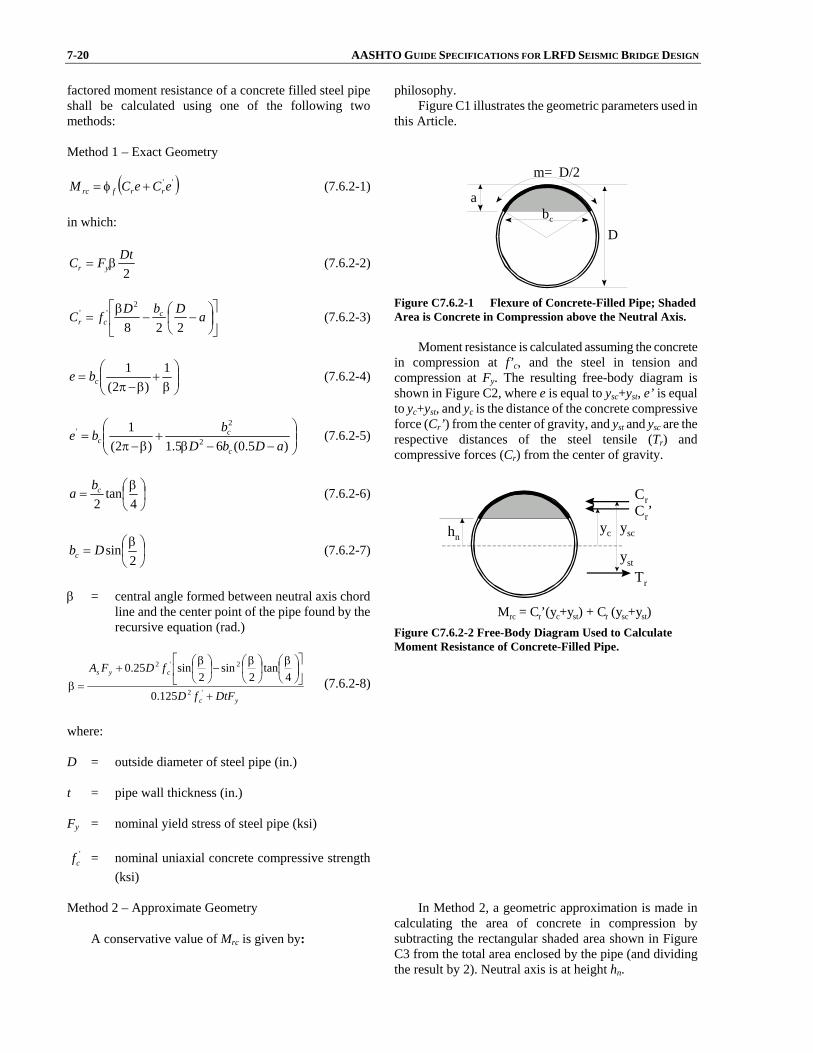
7-20 AASHTO GUIDE SPECIFICATIONS FOR LRFD SEISMIC BRIDGE DESIGN factored moment resistance of a concrete filled steel pipeshall be calculated using one of the following twomethods: Method 1 – Exact Geometry
( )'' eCeCM rrfrc +φ= (7.6.2-1) in which:
2DtFC yr β= (7.6.2-2)
⎥⎦
⎤⎢⎣
⎡⎟⎠⎞
⎜⎝⎛ −−
β= aDbDfC c
cr 228
2'' (7.6.2-3)
⎟⎟⎠
⎞⎜⎜⎝
⎛β
+β−π
=1
)2(1
cbe (7.6.2-4)
⎟⎟⎠
⎞⎜⎜⎝
⎛−−β
+β−π
=)5.0(65.1)2(
12
2'
aDbDbbe
c
cc (7.6.2-5)
⎟⎠⎞
⎜⎝⎛ β
=4
tan2cba (7.6.2-6)
⎟⎠⎞
⎜⎝⎛ β
=2
sinDbc (7.6.2-7)
β = central angle formed between neutral axis chord
line and the center point of the pipe found by therecursive equation (rad.)
yc
cys
DtFfD
fDFA
+
⎥⎦
⎤⎢⎣
⎡⎟⎠⎞
⎜⎝⎛ β
⎟⎠⎞
⎜⎝⎛ β
−⎟⎠⎞
⎜⎝⎛ β
+
=β'2
2'2
125.04
tan2
sin2
sin25.0 (7.6.2-8)
where: D = outside diameter of steel pipe (in.) t = pipe wall thickness (in.) Fy = nominal yield stress of steel pipe (ksi)
'cf = nominal uniaxial concrete compressive strength
(ksi)
philosophy. Figure C1 illustrates the geometric parameters used in
this Article.
m= D/2
b c
D
a
Figure C7.6.2-1 Flexure of Concrete-Filled Pipe; Shaded Area is Concrete in Compression above the Neutral Axis.
Moment resistance is calculated assuming the concrete
in compression at f’c, and the steel in tension and compression at Fy. The resulting free-body diagram is shown in Figure C2, where e is equal to ysc+yst, e’ is equal to yc+yst, and yc is the distance of the concrete compressive force (Cr’) from the center of gravity, and yst and ysc are the respective distances of the steel tensile (Tr) and compressive forces (Cr) from the center of gravity.
y sc h n y c
y st
Mrc = Cr’(yc+y st ) + C r (y sc +y st )
T r
C r ’ C r
Figure C7.6.2-2 Free-Body Diagram Used to Calculate Moment Resistance of Concrete-Filled Pipe.
Method 2 – Approximate Geometry
A conservative value of Mrc is given by:
In Method 2, a geometric approximation is made in calculating the area of concrete in compression by subtracting the rectangular shaded area shown in Figure C3 from the total area enclosed by the pipe (and dividing the result by 2). Neutral axis is at height hn.

SECTION 7: STRUCTURAL STEEL COMPONENTS 7-21
⎥⎦
⎤⎢⎣
⎡⎟⎠⎞
⎜⎝⎛ −−−+−φ= '232 )5.0()5.0(
32)2( cnynfrc fhtDtDFthZM
(7.6.2-9) in which:
)2(42 ''
'
cyc
ccn fFtDf
fAh−+
= (7.6.2-10)
where: φf = 1.0 resistance factor for structural steel in flexure Ac = area of the concrete core (in.2) D = outside diameter of steel pipe (in.) t = pipe wall thickness (in.) Z = plastic section modulus of steel pipe (in.3) Fy = nominal yield stress of steel pipe (ksi)
'cf = nominal concrete compressive strength (ksi)
For capacity design purposes the moment calculated
by this approximate method shall be increased accordingto Article 7.3.
b c
h n
a
b-2t
a
h n
Figure C7.6.2-3 Flexure of Concrete-Filled Pipe – Illustrates Approximation Made in Method 2.
Method 2 (using approximate geometry) gives smaller
moment capacities than Method 1 (exact geometry). The requirement to increase the calculated moment by 10% for capacity design when using the approximate method was established from the ratio of the moment calculated by both methods for a D/t of 10. The moment ratio decreases as D/t increases.
7.6.3 Beams and Connections
Capacity-protected members shall be designed to
resist the forces resulting from hinging in the concrete-filled pipes calculated according to Article 7.6.2.
C7.6.3 Experimental work by Bruneau and Marson (1999),
Shama et al. (2001), Azizinamini et al. (1999), provide examples of full fixity connection details. In some instances, full fixity may not be needed at both ends of columns. Concrete-filled steel pipes, when used in pile bents, only require full moment connection at the pile-cap.
Design details for connecting concrete filled steel pipes to concrete members have been developed by Priestley et al. (1996).
7.7 CONNECTIONS FOR SDC C AND D 7.7.1 Minimum Strength for Connections to Ductile Members
Connections and splices between or within members
having a ductility demand greater than one shall be designed to have a nominal capacity at least 10% greaterthan the nominal capacity of the weaker connectedmember based on expected material properties.
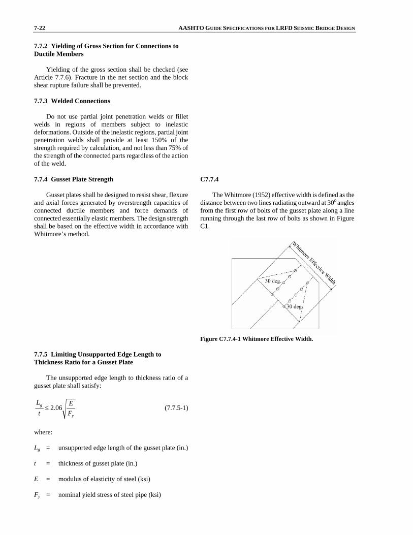
7-22 AASHTO GUIDE SPECIFICATIONS FOR LRFD SEISMIC BRIDGE DESIGN 7.7.2 Yielding of Gross Section for Connections to Ductile Members
Yielding of the gross section shall be checked (see
Article 7.7.6). Fracture in the net section and the blockshear rupture failure shall be prevented.
7.7.3 Welded Connections
Do not use partial joint penetration welds or fillet
welds in regions of members subject to inelasticdeformations. Outside of the inelastic regions, partial jointpenetration welds shall provide at least 150% of thestrength required by calculation, and not less than 75% ofthe strength of the connected parts regardless of the action of the weld.
7.7.4 Gusset Plate Strength
Gusset plates shall be designed to resist shear, flexure
and axial forces generated by overstrength capacities ofconnected ductile members and force demands ofconnected essentially elastic members. The design strengthshall be based on the effective width in accordance withWhitmore’s method.
C7.7.4 The Whitmore (1952) effective width is defined as the
distance between two lines radiating outward at 30o angles from the first row of bolts of the gusset plate along a line running through the last row of bolts as shown in Figure C1.
Figure C7.7.4-1 Whitmore Effective Width.
7.7.5 Limiting Unsupported Edge Length to Thickness Ratio for a Gusset Plate
The unsupported edge length to thickness ratio of a
gusset plate shall satisfy:
y
g
FE
tL
06.2≤ (7.7.5-1)
where: Lg = unsupported edge length of the gusset plate (in.) t = thickness of gusset plate (in.) E = modulus of elasticity of steel (ksi) Fy = nominal yield stress of steel pipe (ksi)

SECTION 7: STRUCTURAL STEEL COMPONENTS 7-23
7.7.6 Gusset Plate Tension Strength
The only acceptable failure mode of gusset plates is
yielding on the gross section that will ensure a ductilefailure mode. The factored tension strength of a gussetplate, φPn, shall be taken as:
⎪⎩
⎪⎨
⎧
φ
φ≤φ=φ
bsbs
unu
ygyng
P
FAFAP (7.7.6-1)
in which: if vntn AA 58.0≥ , then:
tnuvgybs AFAFP += 58.0 (7.7.6-2) if vntn AA 58.0< , then:
tgyvnubs AFAFP += 58.0 (7.7.6-3) where: Avg = gross area of section along the plane resisting
shear in block shear failure mode (in.2) Avn = net area of section along the plane resisting shear
in block shear failure mode (in.2) Atg = gross area of section along the plane resisting
tension in block shear failure mode (in.2) Atn = net area of section along the plane resisting
tension in block shear failure mode (in.2) Ag = gross area of section along the plane resisting
tension (in.2) An = net area of section along the plane resisting
tension (in.2) Fy = nominal yield stress of steel (ksi) Fu = minimum tensile strength of steel (ksi) φbs = 0.80 resistance factor for block shear failure
mechanisms φu = 0.80 resistance factor for fracture on net section φy = 0.95 resistance factor for yield on gross section
C7.7.6 These provisions are similar to those found in Article
6.13 of the AASHTO LRFD Bridge Design Specificationsbut have been modified for seismic design considerations.
Note that the minimum block shear failure mode may be one of several failure modes. Investigation of all potential block shear failure patterns is required todetermine the limiting resistance, Pbs.
The intent of these provisions is ensure that yielding of the gross section occurs prior to fracture on the net section and block shear failure (Caltrans 2001).

7-24 AASHTO GUIDE SPECIFICATIONS FOR LRFD SEISMIC BRIDGE DESIGN 7.7.7 Compression Strength of a Gusset Plate
The nominal compression strength of the gusset
plates, Png, shall be calculated according to AASHTOLRFD Bridge Design Specifications.
7.7.8 In-Plane Moment (Strong Axis)
The nominal yield moment strength of a gusset plate,
ngM , shall be taken as:
ygng FSM = (7.7.8-1) where: Sg = elastic section modulus of gusset plate about the
strong axis (in.3) Fy = nominal yield stress of steel gusset plate (ksi)
The nominal plastic moment strength of a gusset plate, Mpg, shall be taken as:
ygpg FZM = (7.7.8-2)
where: Zg = plastic section modulus of gusset plate about the
strong axis (in.3)
7.7.9 In-Plane Shear Strength
The nominal shear strength of a gusset plate, Vng, shall
be taken as:
yggng FAV 58.0= (7.7.9-1) where: Agg = gross area of gusset plate (in.2) Fy = nominal yield stress of steel gusset plate (ksi)
7.7.10 Combined Moment, Shear, and Axial Forces
The initial yielding strength of a gusset plate subjected
to a combination of in-plane moment, shear and axial forceshall be determined by the following equations:
0.1≤+rg
g
rg
g
MM
PP
(7.7.10-1)
and

SECTION 7: STRUCTURAL STEEL COMPONENTS 7-25
0.12
≤⎟⎟⎠
⎞⎜⎜⎝
⎛+
rg
g
rg
g
VV
PP
(7.7.10-2)
where: Vg = shear force acting on the gusset plate (kip) Mg = moment acting on the gusset plate (kip-in.) Pg = axial force acting on the gusset plate (kip) Mrg = factored nominal yield moment capacity, φMng,
of the gusset plate from Article 7.7.8 (kip-in.) Vrg = factored nominal shear capacity, φVng, of the
gusset plate from Article 7.7.9 (kip) Prg = factored nominal yield axial capacity, φPng, of the
gusset plate from Article 7.7.6 (kip) Full yielding of shear-moment-axial load interaction for a plate shall be:
0.1
12
4
2
≤
⎥⎥
⎦
⎤
⎢⎢
⎣
⎡
⎟⎟⎠
⎞⎜⎜⎝
⎛−
⎟⎟⎠
⎞⎜⎜⎝
⎛
+⎟⎟⎠
⎞⎜⎜⎝
⎛+
rg
g
rg
g
rg
g
rpg
g
PP
VV
PP
MM
(7.7.10-3)
where: Mrpg = factored nominal plastic moment capacity, φMpg,
of the gusset plate from Article 7.7.8 (kip-in.) 7.7.11 Fastener Capacity
Fastener capacity and other related design
requirements shall be determined in accordance withArticle 6.13 of the AASHTO LRFD Bridge DesignSpecifications.
7-26 AASHTO GUIDE SPECIFICATIONS FOR LRFD SEISMIC BRIDGE DESIGN 7.8 ISOLATION DEVICES
Design and detailing of seismic isolation devices shall
be designed in accordance with the provisions of theAASHTO Guide Specifications for Seismic Isolation Design.
C7.8
The requirements for analysis of bridges with seismic isolation are based on the 1999 AASHTO Guide Specifications for Seismic Isolation Design, which provide requirements for modeling seismic isolator units, including the use of property modification factors as given in Article 7.3.
The force-deformation characteristics can be idealized as a bilinear relationship with two key variables: second slope stiffness and characteristic strength. The area under the bilinear curve is equal to the energy dissipated by hysteretic work during cyclic loading. For design, the force-deformation relationship can be represented by an effective stiffness based on the secant stiffness, and a damping coefficient.
Bridges that have elastomeric or sliding bearings at each pier may be designed as isolated structures.
7.9 FIXED AND EXPANSION BEARINGS 7.9.1 Applicability
The provisions shall apply to pin bearings, roller
bearings, rocker bearings, bronze or copper-alloy slidingbearings, elastomeric bearings, spherical bearings, potbearings and disc bearings in common slab-on-steel girderbridges. Curved bridges, seismic isolation-type bearings,and structural fuse bearings are not covered by this section.
C7.9.1 Bearings are important elements of the overall
Earthquake Resistant System of a bridge structure. The 1995 Kobe earthquake, and others that preceded it or have occurred since, clearly showed poor performance of some bearing types and the disastrous consequences that a bearing failure can have on the overall performance of a bridge. A consensus was developed that some testing of bearings would be desirable provided a designer had the option of providing restraints or permitting the bearing to fail if an adequate surface for subsequent movement is provided. An example occurred in Kobe where a bearing failed. The steel diaphragm and steel girder were subsequently damaged because the girder became jammed on the failed bearing and could not move.
There have been a number of studies performed where girders slide either on specially designed bearings or concrete surfaces. A good summary of the range of the results that can be anticipated from these types of analyses can be found in Dicleli and Bruneau (1995).
7.9.2 Design Criteria
The selection of seismic design of bearings shall be
related to the strength and stiffness characteristics of boththe superstructure and the substructure.
Bearing design shall be consistent with the intendedseismic design strategy and the response of the wholebridge system.
Rigid-type bearings are assumed not to move inrestrained directions, and therefore the seismic forces fromthe superstructure shall be assumed to be transmitted through diaphragms or cross frames and their connectionsto the bearings, and then to the substructure withoutreduction due to local inelastic action along that load path.
SECTION 7: STRUCTURAL STEEL COMPONENTS 7-27
Deformable-type bearings having less than fullrigidity in the restrained directions but not specifically designed as base isolators or fuses, have demonstrated a reduction in force transmission and can be used in seismicapplications. The reduced force transmitted through thebearing shall not be less than 0.4 times the bearing deadload reaction. 7.9.3 Design and Detail Requirements
The Engineer shall assess the impact on the lateral
load path due to unequal participation of bearingsconsidering connection tolerances, unintendedmisalignments, the capacity of individual bearings, andskew effects.
Roller bearings or rocker bearings shall not be used innew bridge construction. Expansion bearings and theirsupports shall be designed in such a manner that thestructure can undergo movements in the unrestrained direction not less than the seismic displacementsdetermined from analysis without collapse. Adequatesupport length shall also be provided for fixed bearings.
In their restrained directions, bearings shall bedesigned and detailed to engage at essentially the same movement in each direction.
The frictional resistance of the bearing interfacesliding-surfaces shall be neglected when it contributes toresisting seismic loads. Conversely the frictional resistanceshall be conservatively calculated (i.e., overestimated)when the friction resistance results in the application ofgreater force effects to the structural components.
Elastomeric expansion bearings shall be provided with anchorage to adequately resist the seismically inducedhorizontal forces in excess of those accommodated by shear in the pad. The sole plate and base plate shall bemade wider to accommodate the anchor bolts. Insertsthrough the elastomer shall not be allowed. The anchorbolts shall be designed for the combined effect of bending and shear for seismic loads. Elastomeric fixed bearingsshall be provided with horizontal restraint adequate for thefull horizontal load.
Spherical bearings shall be evaluated for component and connection strength and bearing stability.
Pot and disc bearings should not be used for seismic applications where significant vertical acceleration ispresent. Where the use of pot and disc bearings isunavoidable, they shall be provided with an independent seismically resistant anchorage system.
C7.9.3 The types of tests that are required by these Guide
Specifications are similar to but significantly less extensive than those required for seismically isolated bridges. Each manufacturer is required to conduct a prototype qualification test to qualify a particular bearing type and size for its design forces or displacements. This series of tests only needs to be performed once to qualify the bearing type and size, whereas for seismically isolated bridges, prototype tests are required on every project. The quality control tests required on 1 out of every 10 bearings is the same as that required for every isolator on seismic isolation bridge projects. The cost of the much more extensive prototype and quality control testing of isolation bearings is approximately 10 to 15% of the total bearing cost, which is of the order of 2% of the total bridge cost. The testing proposed herein is much less stringent than that required for isolation bearings and is expected to be less than 0.1% of the total bridge cost. However, the benefits of testing are considered to be significant since owners would have a much higher degree of confidence that each new bearing will perform as designed during an earthquake. The testing capability exists to do these tests on full-size bearings. The owner has the final determination on the extent of the testing requirements as deemed appropriate for the type of bridge considered.
7.9.4 Bearing Anchorage
Sufficient reinforcement shall be provided around the
anchor bolts to develop the horizontal forces and anchorthem into the mass of the substructure unit. Potentialconcrete crack surfaces next to the bearing anchorage shallhave sufficient shear friction capacity to prevent failure.

7-28 AASHTO GUIDE SPECIFICATIONS FOR LRFD SEISMIC BRIDGE DESIGN 7.10 STRUCTURAL STEEL DESIGN REQUIREMENTS FOR ENERGY DISIPATION COMPONENTS IN SDC C AND D
7.10.1 General
The provisions of this article shall apply only to a
limited number of specially detailed steel components designed to dissipate hysteretic energy during earthquakes. This article does not apply to steel members that aredesigned to remain elastic during earthquakes.
For the few specially designed steel members that arewithin the scope of this article, the other requirements ofSection 6 of the AASHTO LRFD Bridge DesignSpecifications are also applicable (unless superseded bymore stringent requirements in this Article).
Continuous and clear load path or load paths shall beassured. Proper load transfer shall be considered indesigning foundations, substructures, superstructures andconnections.
Welds shall be designed as capacity protectedelements. Partial joint penetration groove welds shall notbe used in ductile substructures.
Abrupt changes in cross sections of members inductile substructures are not permitted within the plastichinge zones defined in Article 4.11.8 unless demonstratedacceptable by analysis and supported by research results.
SECTION 8: REINFORCED CONCRETE COMPONENTS
TABLE OF CONTENTS
8-i
8.1 GENERAL.............................................................................................................................................................8-1 8.2 SEISMIC DESIGN CATEGORY A......................................................................................................................8-2 8.3 SEISMIC DESIGN CATEGORIES B, C, AND D................................................................................................8-2
8.3.1 General.........................................................................................................................................................8-2 8.3.2 Force Demands on SDC B...........................................................................................................................8-2 8.3.3 Force Demands on SDC C and D ................................................................................................................8-2 8.3.4 Local Ductility Demands SDC D ................................................................................................................8-3
8.4 PROPERTIES AND APPLICATIONS OF REINFORCING STEEL, PRESTRESSING STEEL AND CONCRETE FOR SDC B, C, AND D .........................................................................................................................8-3
8.4.1 Reinforcing Steel .........................................................................................................................................8-3 8.4.2 Reinforcing Steel Modeling.........................................................................................................................8-3 8.4.3 Prestressing Steel Modeling.........................................................................................................................8-4 8.4.4 Concrete Modeling ......................................................................................................................................8-5
8.5 PLASTIC MOMENT CAPACITY FOR DUCTILE CONCRETE MEMBERS FOR SDC B, C, AND D...........8-6 8.6 SHEAR DEMAND AND CAPACITY FOR DUCTILE CONCRETE MEMBERS FOR SDC B, C, AND D ....8-7
8.6.1 Shear Demand and Capacity........................................................................................................................8-8 8.6.2 Concrete Shear Capacity for SDC B, C, and D............................................................................................8-8 8.6.3 Shear Reinforcement Capacity ..................................................................................................................8-10 8.6.4 Maximum Shear Reinforcement ................................................................................................................8-11 8.6.5 Minimum Shear Reinforcement.................................................................................................................8-12 8.6.6 Shear Reinforcement Capacity of Interlocking Spirals..............................................................................8-12 8.6.7 Minimum Vertical Reinforcement in Interlocking Portion........................................................................8-12 8.6.8 Pier Wall Shear Capacity in the Weak Direction.......................................................................................8-13 8.6.9 Pier Wall Shear Capacity in the Strong Direction .....................................................................................8-13 8.6.10 Pier Wall Minimum Reinforcement.........................................................................................................8-14
8.7 REQUIREMENTS FOR DUCTILE MEMBER DESIGN ..................................................................................8-14 8.7.1 Minimum Lateral Strength.........................................................................................................................8-14 8.7.2 Maximum Axial Load in a Ductile Member in SDC C and D...................................................................8-14
8.8 LONGITUDINAL AND LATERAL REINFORCEMENT REQUIREMENTS.................................................8-15 8.8.1 Maximum Longitudinal Reinforcement.....................................................................................................8-15 8.8.2 Minimum Longitudinal Reinforcement .....................................................................................................8-15 8.8.3 Splicing of Longitudinal Reinforcement in Columns Subject to Ductility Demands for SDC C and D....8-16 8.8.4 Minimum Development Length of Reinforcing Steel for SDC C and D...................................................8-16 8.8.5 Anchorage of Bundled Bars in Ductile Components for SDC C and D ....................................................8-17 8.8.6 Maximum Bar Diameter for SDC C and D................................................................................................8-17 8.8.7 Lateral Reinforcement Inside the Plastic Hinge Region for SDC C and D................................................8-17 8.8.8 Lateral Column Reinforcement Outside the Plastic Hinge Region for SDC C and D ...............................8-18 8.8.9 Requirements for Lateral Reinforcement for SDC C and D ......................................................................8-18 8.8.10 Development Length for Column Bars Extended Into Oversized Pile Shafts for SDC C and D.............8-19 8.8.11 Lateral Reinforcement Requirements for Columns Supported on Oversized Pile Shafts for SDC C and D..................................................................................................................................................8-20 8.8.12 Lateral Confinement for Oversized Pile Shafts for SDC C and D...........................................................8-20 8.8.13 Lateral Confinement for Non-Oversized Strengthened Pile Shafts for SDC C and D.............................8-20
8.9 REQUIREMENTS FOR CAPACITY PROTECTED MEMBERS.....................................................................8-20 8.10 SUPERSTRUCTURE CAPACITY DESIGN FOR LONGITUDINAL DIRECTION FOR SDC C AND D...8-21 8.11 SUPERSTRUCTURE CAPACITY DESIGN FOR TRANSVERSE DIRECTION (INTEGRAL BENT CAP) FOR SDC C AND D .............................................................................................................................8-22 8.12 SUPERSTRUCTURE DESIGN FOR NON-INTEGRAL BENT CAPS FOR SDC C AND D ........................8-23 8.13 JOINT DESIGN FOR SDC C AND D ..............................................................................................................8-24
8.13.1 Joint Performance ....................................................................................................................................8-24 8.13.2 Joint Proportioning ..................................................................................................................................8-24 8.13.3 Minimum Joint Shear Reinforcing...........................................................................................................8-25 8.13.4 Integral Bent Cap Joint Shear Design ......................................................................................................8-26
8.13.4.1 Joint Description............................................................................................................................8-26 8.13.4.2 Joint Shear Reinforcement.............................................................................................................8-27

8-ii AASHTO GUIDE SPECIFICATIONS FOR LRFD SEISMIC BRIDGE DESIGN
8.13.4.2.1 Vertical Stirrups...................................................................................................................8-27 8.13.4.2.2 Horizontal Stirrups...............................................................................................................8-29 8.13.4.2.3 Horizontal Side Reinforcement............................................................................................8-29 8.13.4.2.4 J-Bars ...................................................................................................................................8-29
8.13.5 Non-Integral Bent Cap Joint Shear Design ..............................................................................................8-30 8.13.5.1 Joint Shear Reinforcement.............................................................................................................8-30
8.13.5.1.1 Vertical Stirrups Outside the Joint Region ..........................................................................8-30 8.13.5.1.2 Vertical Stirrups Inside the Joint Region .............................................................................8-32 8.13.5.1.3 Additional Longitudinal Cap Beam Reinforcement ............................................................8-32 8.13.5.1.4 Horizontal J-Bars .................................................................................................................8-32
8.14 COLUMN FLARES FOR SDC C AND D........................................................................................................8-33 8.14.1 Horizontally Isolated Flares .....................................................................................................................8-33 8.14.2 Integral Column Flares.............................................................................................................................8-33 8.14.3 Flare Reinforcement.................................................................................................................................8-33
8.15 COLUMN SHEAR KEY DESIGN FOR SDC C AND D .................................................................................8-34 8.16 CONCRETE PILES...........................................................................................................................................8-34
8.16.1 Transverse Reinforcement Requirements ................................................................................................8-34 8.16.2 Cast-In-Place and Precast Concrete Piles.................................................................................................8-34
SECTION 8
REINFORCED CONCRETE COMPONENTS
8-1
Chapter 8 8.1 GENERAL C8.1
Design and construction of concrete components
that include superstructures, columns, piers, footingsand their connections shall conform to the requirementsof this Section.
For the purpose of this article, a vertical supportshall be considered to be a column if the ratio of theclear height to the maximum plan dimensions of the support is greater than 2.5. For a flared column, themaximum plan dimension shall be taken at the minimum section of the flare. For supports with a ratio less than2.5, the provisions for piers of Articles 8.6.8 to 8.6.10shall apply.
A pier shall be designed as a pier member in itsstrong direction and a column in its weak direction.
The pile extensions of pile bents as well as drilledshafts and caissons shall be regarded as columns for design and detailing purposes.
If architectural flares or other treatments areprovided to columns adjacent to potential plastic hingezones, they shall be “structurally isolated” in such a waythat they do not add to the flexural strength capacity of the columns. If “structural isolation” is not used then thecolumn and adjacent structural elements shall bedesigned to resist the forces generated by increasedflexural strength capacity according to Article 8.14.
The 1989 Loma Prieta and 1994 Northridge earthquakes confirmed the vulnerability of columns with inadequate transverse reinforcement and inadequate anchorage of longitudinal reinforcement. Also of concern are:
• lack of adequate reinforcement for positive moments that may occur in the superstructure over monolithic supports when the structure is subjected to longitudinal dynamic loads
• lack of adequate shear strength in joints
between columns and bent caps under transverse dynamic loads
• inadequate reinforcement for torsion,
particularly in outrigger-type bent caps
• inadequate transverse reinforcement for shear and for restraint against global buckling of longitudinal bars (“bird caging”)
The purpose of the design is to ensure that a column
is provided with adequate ductility and is forced to yield in flexure and that the potential for a shear, compression failure due to longitudinal bar buckling, or loss of anchorage mode of failure is minimized.
The actual ductility demand on a column or pier is a complex function of a number of variables, including:
• Earthquake characteristics, including duration, frequency content and near-field (or pulse) effects
• Design force level
• Periods of vibration of the bridge
• Shape of the inelastic hysteresis loop of the
columns, and hence effective hysteretic damping
• Elastic damping coefficient
• Contributions of foundation and soil conditions
to structural flexibility
• Spread of plasticity (plastic hinge length) in the column
The damage potential of a column is also related to
the ratio of the duration of strong ground shaking to the
8-2 AASHTO GUIDE SPECIFICATIONS FOR LRFD SEISMIC BRIDGE DESIGN
natural period of vibration of the bridge. The definition of a column in this article is provided
as a guideline to differentiate between the additional design requirements for a wall-type pier and the requirements for a column.
Certain oversize columns exist for architectural or aesthetic reasons. These columns, if fully reinforced, place excessive demands of moment, shear, or both, on adjoining elements. The designer should strive to “isolate structurally” those architectural elements that do not form part of the primary energy dissipation system that are located either within or in close proximity to plastic hinge zones. Nevertheless, the architectural elements should remain serviceable throughout the life of the structure. For this reason, minimum steel for temperature and shrinkage should be provided. When architectural flares are not isolated, Article 8.14.2 requires that the design shear force for a flared column be the worst case calculated using the overstrength moment of the oversized flare or the shear generated by a plastic hinge at the bottom of the flare.
8.2 SEISMIC DESIGN CATEGORY A
No consideration of seismic forces is required forthe design of structural components except for thedesign of the connection for the superstructure to thesubstructure as specified in Article 4.6 and the minimum support length as specified in Article 4.12.
8.3 SEISMIC DESIGN CATEGORIES B, C, AND D 8.3.1 General
Initial sizing of columns can be performed usingStrength and Service load combinations defined in theAASHTO LRFD Bridge Design Specifications.
C8.3.1 For post-tensioned box-girders, it is recommended
that the least dimension of column or pier wall be less than or equal to the superstructure depth. See Article 8.10.
8.3.2 Force Demands on SDC B
The design forces shall be the lesser of the forcesresulting from the overstrength plastic hinging momentcapacity or unreduced elastic seismic forces in columnsor pier walls. Force demands shall be less than capacities established in Articles 8.5 and 8.6.
C8.3.2
SDC B structures are designed and detailed to achieve a displacement ductility, μD, of at least 2.
8.3.3 Force Demands on SDC C and D
The design forces shall be based on forces resulting from the overstrength plastic hinging moment capacityor the maximum connection capacity following thecapacity design principles specified in Article 4.11.
For SDC D where liquefaction is identified, plastichinging in the foundation is acceptable as specified in Article 3.3.
SECTION 8: REINFORCED CONCRETE COMPONENTS 8-3
8.3.4 Local Ductility Demands SDC D
The local displacement ductility demands, μD, of members shall be determined based on the analysismethod adopted in Section 5. The local displacementductility demand shall not exceed the maximumallowable displacement ductilities established in Article4.9.
8.4 PROPERTIES AND APPLICATIONS OF REINFORCING STEEL, PRESTRESSING STEEL AND CONCRETE FOR SDC B, C, AND D
For SDC B and C, the expected material propertiesshall be used to determine the section stiffness andoverstrength capacities.
For SDC D, the expected material properties shall be used to determine section stiffness, overstrengthcapacities, and displacement capacities.
8.4.1 Reinforcing Steel
Reinforcing bars, deformed wire, cold-drawn wire, welded plain wire fabric, and welded deformed wirefabric shall conform to the material standards asspecified in the AASHTO LRFD Bridge DesignSpecifications.
High strength high alloy bars with an ultimatetensile strength of up to 250 ksi, are permitted be usedfor longitudinal column reinforcement for seismicloading provided that it can be demonstrated through testing that the low cycle fatigue properties are notinferior to normal reinforcing steels with yield strengthsof 75 ksi or less.
C8.4.1
High-strength reinforcement reduces congestion and cost as demonstrated by Mander and Cheng (1999). However it is important to ensure that the cyclic fatigue life is not inferior when compared to ordinary mild steel reinforcing bars. Mander, Panthaki, and Kasalanati, (1994) have shown that modern high-alloy prestressing threadbar steels can have sufficient ductility to justify their use in seismic design.
The modulus of toughness is defined as the area beneath the monotonic tensile stress-strain curve from initial loading (zero stress) to fracture.
Wire rope or strand is permitted to be used for spirals in columns if it can be shown through testing thatthe modulus of toughness exceeds 14 ksi.
For SDC B and C, ASTM A 706 or ASTM A 615Grade 60 reinforcing steel is permitted.
For SDC D, ASTM A 706 reinforcing steel inmembers where plastic hinging is expected shall be used.
8.4.2 Reinforcing Steel Modeling
Reinforcing steel shall be modeled with a stress-
strain relationship that exhibits an initial elastic portion,a yield plateau, and a strain hardening range in whichthe stress increases with strain, as shown in Figure 1. In lieu of specific data, the steel reinforcement propertiesprovided in Table 1 should be used.
Within the elastic region the modulus of elasticity, Es, shall be taken as 29,000 ksi.
C8.4.2 The steel reinforcement properties provided in
Table 1 are based upon data collected by Caltrans.
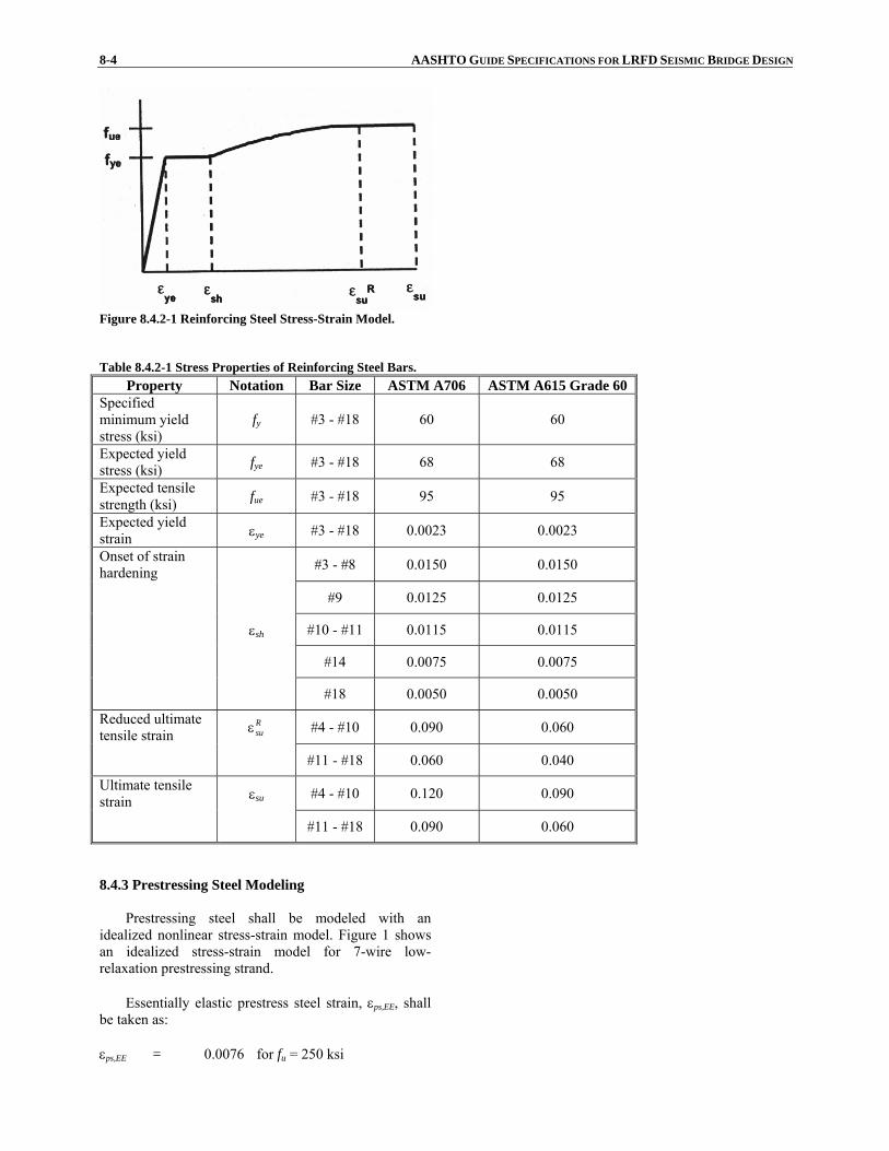
8-4 AASHTO GUIDE SPECIFICATIONS FOR LRFD SEISMIC BRIDGE DESIGN
Figure 8.4.2-1 Reinforcing Steel Stress-Strain Model. Table 8.4.2-1 Stress Properties of Reinforcing Steel Bars.
Property Notation Bar Size ASTM A706 ASTM A615 Grade 60 Specified minimum yield stress (ksi)
fy #3 - #18 60 60
Expected yield stress (ksi) fye #3 - #18 68 68
Expected tensile strength (ksi) fue #3 - #18 95 95
Expected yield strain εye #3 - #18 0.0023 0.0023
Onset of strain hardening #3 - #8 0.0150 0.0150
#9 0.0125 0.0125
εsh #10 - #11 0.0115 0.0115
#14 0.0075 0.0075
#18 0.0050 0.0050
Reduced ultimate tensile strain
Rsuε #4 - #10 0.090 0.060
#11 - #18 0.060 0.040
Ultimate tensile strain εsu #4 - #10 0.120 0.090
#11 - #18 0.090 0.060
8.4.3 Prestressing Steel Modeling
Prestressing steel shall be modeled with anidealized nonlinear stress-strain model. Figure 1 showsan idealized stress-strain model for 7-wire low-relaxation prestressing strand.
Essentially elastic prestress steel strain, εps,EE, shall
be taken as: εps,EE = 0.0076 for fu = 250 ksi

SECTION 8: REINFORCED CONCRETE COMPONENTS 8-5
and, εps,EE = 0.0086 for fu = 270 ksi
Reduced ultimate prestress steel strain shall be taken as:
Rups,ε = 0.03
The stress, fps, in the prestressing steel shall be taken
as:
For 250 ksi strands:
0.0076 when 500,28 ≤εε= pspspsf (8.4.3-1)
0.0076 when 0.25-250 >εε
= psps
psf (8.4.3-2)
For 270 ksi strands:
0.0086 when 500,28 ≤εε= pspspsf (8.4.3-3)
0086.0 when 007.0
0.04-270 >ε−ε
= psps
psf (8.4.3-4)
where: εps = strain in prestressing steel
Figure 8.4.3-1 Prestressing Strand Stress-Strain Model. 8.4.4 Concrete Modeling
A stress-strain model for confined and unconfined concrete shall be used. Mander’s stress strain model for
C8.4.4 For more information on Mander’s confined
concrete model, refer to Mander et al. (1988), Mander et
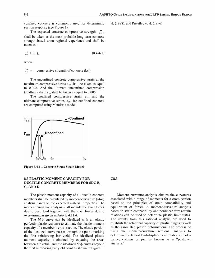
8-6 AASHTO GUIDE SPECIFICATIONS FOR LRFD SEISMIC BRIDGE DESIGN confined concrete is commonly used for determiningsection response (see Figure 1).
The expected concrete compressive strength, cef ′ , shall be taken as the most probable long-term concretestrength based upon regional experience and shall betaken as:
1.3ce cf f′ ′≥ (8.4.4-1) where:
cf ′ = compressive strength of concrete (ksi)
The unconfined concrete compressive strain at themaximum compressive stress εco shall be taken as equalto 0.002. And the ultimate unconfined compression(spalling) strain εsp shall be taken as equal to 0.005.
al. (1988), and Priestley et al. (1996)
The confined compressive strain, εcc, and the ultimate compressive strain, εcu, for confined concreteare computed using Mander’s model.
Figure 8.4.4-1 Concrete Stress-Strain Model. 8.5 PLASTIC MOMENT CAPACITY FOR DUCTILE CONCRETE MEMBERS FOR SDC B, C, AND D
C8.5
The plastic moment capacity of all ductile concrete
members shall be calculated by moment-curvature (M-φ) analysis based on the expected material properties. The moment curvature analysis shall include the axial forcesdue to dead load together with the axial forces due to overturning as given in Article 4.11.4.
The M-φ curve can be idealized with an elastic perfectly plastic response to estimate the plastic momentcapacity of a member’s cross section. The elastic portionof the idealized curve passes through the point markingthe first reinforcing bar yield. The idealized plasticmoment capacity is obtained by equating the areasbetween the actual and the idealized M-φ curves beyondthe first reinforcing bar yield point as shown in Figure 1.
Moment curvature analysis obtains the curvatures associated with a range of moments for a cross section based on the principles of strain compatibility and equilibrium of forces. A moment-curvature analysis based on strain compatibility and nonlinear stress-strain relations can be used to determine plastic limit states. The results from this rational analysis are used to establish the rotational capacity of plastic hinges as well as the associated plastic deformations. The process of using the moment-curvature sectional analysis to determine the lateral load-displacement relationship of a frame, column or pier is known as a “pushover analysis.”
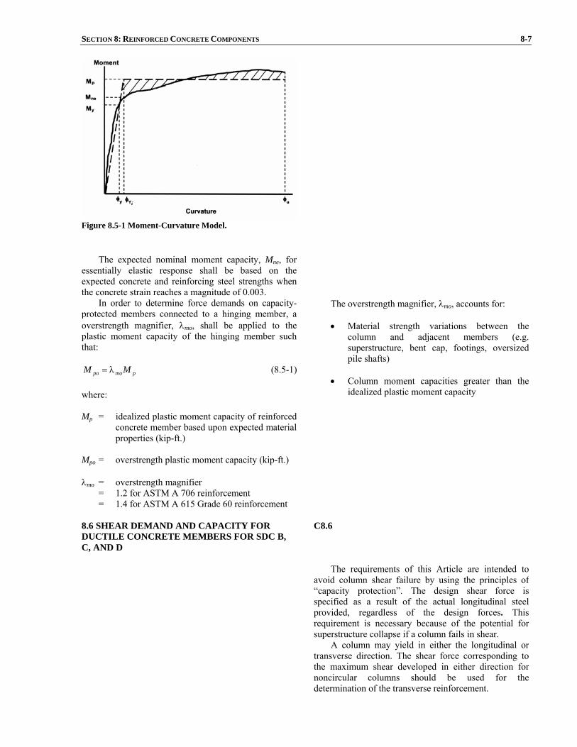
SECTION 8: REINFORCED CONCRETE COMPONENTS 8-7
Figure 8.5-1 Moment-Curvature Model.
8.6 SHEAR DEMAND AND CAPACITY FOR DUCTILE CONCRETE MEMBERS FOR SDC B, C, AND D
C8.6
The requirements of this Article are intended to
avoid column shear failure by using the principles of “capacity protection”. The design shear force is specified as a result of the actual longitudinal steel provided, regardless of the design forces. This requirement is necessary because of the potential for superstructure collapse if a column fails in shear.
A column may yield in either the longitudinal or transverse direction. The shear force corresponding to the maximum shear developed in either direction for noncircular columns should be used for the determination of the transverse reinforcement.
The expected nominal moment capacity, Mne, for
essentially elastic response shall be based on theexpected concrete and reinforcing steel strengths whenthe concrete strain reaches a magnitude of 0.003.
In order to determine force demands on capacity-protected members connected to a hinging member, aoverstrength magnifier, λmo, shall be applied to theplastic moment capacity of the hinging member suchthat:
pmopo MM λ= (8.5-1) where: Mp = idealized plastic moment capacity of reinforced
concrete member based upon expected materialproperties (kip-ft.)
Mpo = overstrength plastic moment capacity (kip-ft.) λmo = overstrength magnifier = 1.2 for ASTM A 706 reinforcement = 1.4 for ASTM A 615 Grade 60 reinforcement
The overstrength magnifier, λmo, accounts for:
• Material strength variations between the column and adjacent members (e.g. superstructure, bent cap, footings, oversized pile shafts)
• Column moment capacities greater than the
idealized plastic moment capacity

8-8 AASHTO GUIDE SPECIFICATIONS FOR LRFD SEISMIC BRIDGE DESIGN
8.6.1 Shear Demand and Capacity
The shear demand for a column, Vu, in SDC B shallbe determined based on the lesser of:
• The force obtained from an elastic linear analysis
• The force, Vpo, corresponding to plastic hinging
of the column including an overstrength factor
The shear demand for a column, Vu, in SDC C or Dshall be determined based on the force, Vpo, associated with the overstrength moment, Mpo, defined in Article8.5 and outlined in Article 4.11.
The column shear strength capacity shall becalculated based on the nominal material strengthproperties and satisfy:
uns VV ≥φ (8.6.1-1) in which:
scn VVV += (8.6.1-2) where: φs = 0.85 for shear in reinforced concrete Vn = nominal shear capacity of member (kip) Vc = concrete contribution to shear capacity as
defined in Article 8.6.2 (kip) Vs = reinforcing steel contribution to shear capacity
as defined in Article 8.6.3 (kip)
8.6.2 Concrete Shear Capacity for SDC B, C, and D
The concrete shear capacity, Vc, of membersdesigned for SDC B, C and D shall be taken as:
ecc AvV = (8.6.2-1) in which:
ge AA 8.0= (8.6.2-2) if Pu is compressive:
ccg
uc ff
APv ′≤′⎟
⎟⎠
⎞⎜⎜⎝
⎛+α′= 11.0
21 (8.6.2-3)
otherwise:

SECTION 8: REINFORCED CONCRETE COMPONENTS 8-9
vc = 0 (8.6.2-4) for circular columns with spiral or hoop reinforcing:
yhsD
fρμ
=α03.0' (8.6.2-5)
'
4sDAsp
s =ρ (8.6.2-6)
for rectangular columns with ties:
yhwD
fρμ
=α06.0' (8.6.2-7)
bsAv
w =ρ (8.6.2-8)
where: Ag = gross area of member cross section (in.2) Pu = ultimate compressive force acting on section
(kip) Asp = area of spiral or hoop reinforcement (in.2) s = pitch of spiral or spacing of hoops or ties (in.) D’ = diameter of spiral or hoop for circular column
(in.) Av = cross sectional area of shear reinforcing in the
direction of loading (in.2) b = width of rectangular column (in.) fyh = nominal yield stress of transverse reinforcing
(ksi)
'cf = nominal concrete compressive strength (ksi)
μD = maximum local displacement ductility ratio of
member at cross section of interest The concrete shear capacity, Vc, of a section outside
the plastic hinge region as defined in Article 4.11.7 shall be determined with:
μD = 1
For SDC B, the concrete shear capacity of a sectionwithin the plastic hinge region shall be determined with: μD = 2
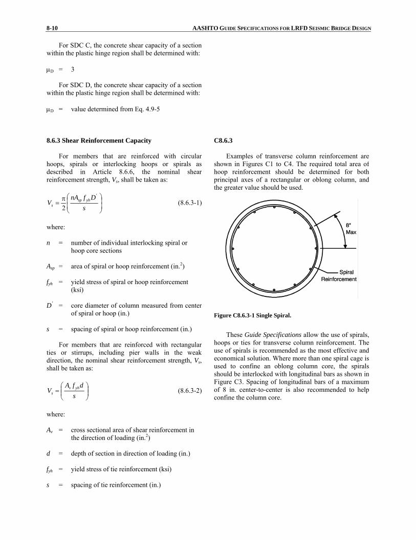
8-10 AASHTO GUIDE SPECIFICATIONS FOR LRFD SEISMIC BRIDGE DESIGN
For SDC C, the concrete shear capacity of a sectionwithin the plastic hinge region shall be determined with: μD = 3
For SDC D, the concrete shear capacity of a section
within the plastic hinge region shall be determined with: μD = value determined from Eq. 4.9-5
8.6.3 Shear Reinforcement Capacity
For members that are reinforced with circular hoops, spirals or interlocking hoops or spirals asdescribed in Article 8.6.6, the nominal shearreinforcement strength, Vs, shall be taken as:
⎟⎟⎠
⎞⎜⎜⎝
⎛π=
sDfnA
V yhsps
'
2 (8.6.3-1)
where: n = number of individual interlocking spiral or hoop core sections Asp = area of spiral or hoop reinforcement (in.2) fyh = yield stress of spiral or hoop reinforcement (ksi) D’ = core diameter of column measured from center
of spiral or hoop (in.) s = spacing of spiral or hoop reinforcement (in.)
For members that are reinforced with rectangularties or stirrups, including pier walls in the weakdirection, the nominal shear reinforcement strength, Vs, shall be taken as:
⎟⎟⎠
⎞⎜⎜⎝
⎛=
sdfA
V yhvs (8.6.3-2)
where: Av = cross sectional area of shear reinforcement in the direction of loading (in.2) d = depth of section in direction of loading (in.) fyh = yield stress of tie reinforcement (ksi) s = spacing of tie reinforcement (in.)
C8.6.3
Examples of transverse column reinforcement are shown in Figures C1 to C4. The required total area of hoop reinforcement should be determined for both principal axes of a rectangular or oblong column, and the greater value should be used.
Figure C8.6.3-1 Single Spiral.
These Guide Specifications allow the use of spirals,
hoops or ties for transverse column reinforcement. The use of spirals is recommended as the most effective and economical solution. Where more than one spiral cage is used to confine an oblong column core, the spirals should be interlocked with longitudinal bars as shown in Figure C3. Spacing of longitudinal bars of a maximum of 8 in. center-to-center is also recommended to help confine the column core.
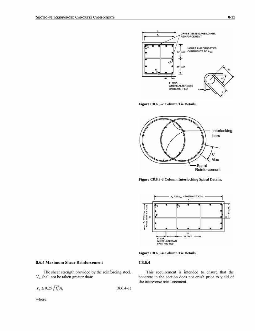
SECTION 8: REINFORCED CONCRETE COMPONENTS 8-11
Figure C8.6.3-2 Column Tie Details.
Figure C8.6.3-3 Column Interlocking Spiral Details.
Figure C8.6.3-4 Column Tie Details.
8.6.4 Maximum Shear Reinforcement
The shear strength provided by the reinforcing steel,Vs, shall not be taken greater than:
ecs AfV ′≤ 25.0 (8.6.4-1) where:
C8.6.4
This requirement is intended to ensure that the concrete in the section does not crush prior to yield of the transverse reinforcement.

8-12 AASHTO GUIDE SPECIFICATIONS FOR LRFD SEISMIC BRIDGE DESIGN Ae = effective area of the cross section for shear resistance as defined by Eq. 8.6.2-2 (in.2)
cf ′ = compressive strength of concrete (ksi) 8.6.5 Minimum Shear Reinforcement
The area of column spiral reinforcement, Asp, and
column web reinforcement, Av, are defined based uponthe reinforcement ratios, ρs and ρw as given by Eq. 8.6.2-6 and Eq. 8.6.2-8, respectively. The spiral reinforcement ratio, ρs, for each individual circular core of a columnand the minimum web reinforcement ratio, ρw, shall satisfy:
For SDC B,
003.0≥ρs (8.6.5-1)
003.0≥ρw (8.6.5-2) For SDC C and D,
005.0≥ρs (8.6.5-3)
005.0≥ρw (8.6.5-4)
8.6.6 Shear Reinforcement Capacity of Interlocking Spirals
The shear reinforcement strength provided by
interlocking spirals or hoops shall be taken as the sum ofall individual spiral or hoop shear strengths calculated inaccordance with Eq. 8.6.3-1.
8.6.7 Minimum Vertical Reinforcement in Interlocking Portion
The longitudinal reinforcing bars in the interlockingportion of the column shall have a maximum spacing of8 in. and need not be anchored in the footing or the bentcap unless deemed necessary for the flexural capacity ofthe column. The longitudinal reinforcing bar size in theinterlocking portion of the column shall be chosencorrespondingly to the reinforcing bars outside theinterlocking portion as shown in Table 1. Table 8.6.7-1 Reinforcement Size for Interlocking Portion of Columns.
Minimum Size of bars required inside the
interlocking portion
Size of bars used outside the
interlocking portion #6 #10 #8 #11 #9 #14
#11 #18

SECTION 8: REINFORCED CONCRETE COMPONENTS 8-13
8.6.8 Pier Wall Shear Capacity in the Weak Direction
The shear capacity for pier walls in the weakdirection shall be determined according to Articles 8.6.1,8.6.2 and 8.6.3.
8.6.9 Pier Wall Shear Capacity in the Strong Direction
The factored nominal shear capacity of pier walls inthe strong direction, φVn, shall be greater than themaximum shear demand, Vu, as specified in Eq. 1. The maximum shear demand, Vu, need not be taken greaterthan the lesser of:
• the overstrength capacity of the superstructure
to substructure connection
• the overstrength capacity of the foundation
• the force demands determined in accordancewith Article 8.3
• the unreduced elastic demand obtained whenusing analysis procedure 1 or 2 from Article4.2.
C8.6.9
uns VV ≥φ (8.6.9-1)
in which:
( ) ecyhhcn AfbdffV '25.013.0 ≤ρ+′= (8.6.9-2)
bsAv
h =ρ (8.6.9-3)
where: φs = 0.85 for shear in reinforced concrete Av = cross sectional area of shear reinforcement in the direction of loading (in.2) d = depth of section in direction of loading (in.) b = width of section (in.) fyh = yield stress of tie reinforcement (ksi)
cf ′ = compressive strength of concrete (ksi) s = spacing of tie reinforcement (in.) Ae = effective area of the cross section for shear
resistance as defined by Eq. 8.6.2-2 (in.2)
Studies of squat shear walls have demonstrated thatthe large shear stresses associated with the moment capacity of the wall may lead to a sliding failure brought about by crushing of the concrete at the base of the wall. The thickness of pier walls shall be selected such that the shear stress satisfies the upper limit specified in Eq. 2.

8-14 AASHTO GUIDE SPECIFICATIONS FOR LRFD SEISMIC BRIDGE DESIGN 8.6.10 Pier Wall Minimum Reinforcement
The horizontal reinforcement ratio, ρh, shall not beless than 0.0025. The vertical reinforcement ratio, ρv, shall not be less than the horizontal reinforcement ratio.
Reinforcement spacing, either horizontally orvertically, shall not exceed 18 in.
The reinforcement required for shear shall becontinuous and shall be distributed uniformly.Horizontal and vertical layers of reinforcement shall beprovided on each face of a pier. Splices in horizontalpier reinforcement shall be staggered.
C8.6.10
The requirement that ρv ≥ ρh is intended to avoid the possibility of having inadequate web reinforcement in piers which are short in comparison to their height.
Stagger splices to avoid weakened sections.
8.7 REQUIREMENTS FOR DUCTILE MEMBER DESIGN
8.7.1 Minimum Lateral Strength
The minimum lateral flexural capacity of eachcolumn shall be taken as:
( 0.5 )
0.1 h sne trib
H DM P
+≥
Λ (8.7.1-1)
where: Mne = nominal moment capacity of the column based
upon expected material properties as shown inFigure 8.5-1(kip-ft.)
Ptrib = greater of the dead load per column or force
associated with the tributary seismic masscollected at the bent (kip)
Hh = the height from the top of the footing to the top
of the column or the equivalent column heightfor a pile extension column (ft.)
Ds = depth of superstructure (ft.) Λ = fixity factor for the column defined in Article
4.8.1
The flexural capacity of pile extension membersand pier walls in the weak direction shall also satisfy therequirements of Eq. 1 when the ductility demand is greater than one.
8.7.2 Maximum Axial Load in a Ductile Member in SDC C and D
The maximum axial load acting on a column or pierwhere the ductility demand, μD, is greater than 2 and amoment-curvature pushover analysis is not performed

SECTION 8: REINFORCED CONCRETE COMPONENTS 8-15
shall satisfy:
gcu AfP '2.0≤ (8.7.2-1)
where: Pu = ultimate compressive force acting on the
section including seismic induced verticaldemands (kip)
cf ′ = compressive strength of concrete (ksi)
Ag = gross area of member cross section (in.2)
A higher axial load value, Pu, can be used providedthat a moment-curvature pushover analysis is performedto compute the maximum ductility capacity of themember.
8.8 LONGITUDINAL AND LATERAL REINFORCEMENT REQUIREMENTS
8.8.1 Maximum Longitudinal Reinforcement
The area of longitudinal reinforcement forcompression members shall satisfy:
gl AA 04.0≤ (8.8.1-1) where: Ag = gross area of member cross section (in.2) Al = area of longitudinal reinforcement in member
(in.2)
C8.8.1 This requirement is intended to apply to the full
section of the columns. The maximum ratio is to avoid congestion and extensive shrinkage cracking and to permit anchorage of the longitudinal steel, but most importantly, the smaller the amount of longitudinal reinforcement, the greater the ductility of the column.
8.8.2 Minimum Longitudinal Reinforcement
The minimum area of longitudinal reinforcementfor compression members shall not be less than:
For columns in SDC B and C,
gl AA 007.0≥ (8.8.2-1) For columns in SDC D,
gl AA 010.0≥ (8.8.2-2) For pier walls in SDC B and C,
gl AA 0025.0≥ (8.8.2-3) For pier walls in SDC D,
gl AA 005.0≥ (8.8.2-4)
C8.8.2 This requirement is intended to apply to the full
section of the columns. The lower limit on the column or wall reinforcement reflects the traditional concern for the effect of time-dependent deformations as well as the desire to avoid a sizable difference between the flexural cracking and yield moments.

8-16 AASHTO GUIDE SPECIFICATIONS FOR LRFD SEISMIC BRIDGE DESIGN where: Ag = gross area of member cross section (in.2) Al = area of longitudinal reinforcement in member
(in.2)
8.8.3 Splicing of Longitudinal Reinforcement in Columns Subject to Ductility Demands for SDC C and D
Splicing of longitudinal column reinforcement in SDC C or D shall be outside the plastic hinging region as defined in Article 4.11.7, except as permitted below.
For a pile or shaft in SDC D where liquefaction isanticipated, the zone comprising the location of potentialplastic hinging in the liquefied and non-liquefied casescan be large. For a pile or shaft in SDC D where splicingin the zone cannot be avoided, use mechanical couplersthat are capable of developing the expected tensilestrength of the bars and as approved by the owner.
C8.8.3
It is often desirable to lap longitudinal
reinforcement with dowels at the column base. This is undesirable for seismic performance because:
• the splice occurs in a potential plastic hinge region where requirements for bond are criticaland,
• lapping the main reinforcement will tend to
concentrate plastic deformation close to the base and reduce the effective plastic hinge length as a result of stiffening of the column over the lapping region. This may result in a severe local curvature demand.
8.8.4 Minimum Development Length of Reinforcing Steel for SDC C and D
Column longitudinal reinforcement shall beextended into footings and cap beams as close aspractically possible to the opposite face of the footing orcap beam.
The anchorage length for longitudinal column barsdeveloped into the cap beam or footing for seismic loadsshall satisfy:
'
79.0
c
yeblac
f
fdl ≥ (8.8.4-1)
where: lac = anchored length of longitudinal reinforcing bars
into the cap beam or footing (in.) dbl = diameter of longitudinal column bar (in.) fye = expected yield stress of longitudinal
reinforcement (ksi)
cf ′ = nominal compressive strength of concrete (ksi) For SDC D, the anchorage length shall not be
reduced by means of adding hooks or mechanicalanchorage devices. If hooks are provided, the tailsshould be pointed inwards towards the joint core.

SECTION 8: REINFORCED CONCRETE COMPONENTS 8-17
8.8.5 Anchorage of Bundled Bars in Ductile Components for SDC C and D
The anchorage length of individual column barswithin a bundle anchored into a cap beam shall beincreased by 20% for a two-bar bundle and 50% for athree-bar bundle. Four-bar bundles are not permitted inductile elements.
8.8.6 Maximum Bar Diameter for SDC C and D
In order to ensure adequate bond to concrete, the nominal diameter of longitudinal reinforcement, dbl, in columns shall satisfy:
ye
ccbl f
DLfd
)5.0(79.0 ' −≤ (8.8.6-1)
where: L = length of column form the point of contra- flexure to the point of maximum moment based upon capacity design principles (in.) Dc = diameter or depth of column in direction of loading (in.)
cf ′ = nominal compressive strength of concrete (ksi) fye = the expected yield strength (ksi)
Where longitudinal bars in columns are bundled, therequirement of adequate bond (Eq. 1) shall be checkedfor the effective bar diameter, assumed as 1.2dbl, for two-bar bundles, and 1.5dbl for three-bar bundles.
C8.8.6 In short columns, where plastic hinges of opposite
sign develop simultaneously at the top and bottom of the column, bond conditions caused by the requirement to transfer force from bar to concrete as a result of the rapidly changing moment may be extreme. It is thus important to use smaller diameter bars in such situations (Priestley et al. 1996).
8.8.7 Lateral Reinforcement Inside the Plastic Hinge Region for SDC C and D
The volume of lateral reinforcement, ρs or ρw, (as defined in Article 8.6.2) provided inside the plastichinge region (as defined in Article 4.11.7) shall besufficient to ensure that the column or pier wall hasadequate shear capacity and confinement level toachieve the required ductility capacity.
C8.8.7 These provisions ensure that the concrete is
adequately confined so that the transverse hoops will not prematurely fracture as a result of the plastic work done on the critical column section. For typical bridge columns with low levels of axial load, these equations rarely govern, but should be checked.
If a section has been detailed in accordance with the transverse reinforcement requirement of these guide specifications, then the section is assumed to be ‘capacity protected’ against undesirable modes of failure such as shear, buckling of longitudinal bars, and concrete crushing due to lack of confinement.
Longitudinal reinforcing bars in potential plastic hinge zones may be highly strained in compression to the extent that they may buckle. Buckling of longitudinal reinforcing may be either:

8-18 AASHTO GUIDE SPECIFICATIONS FOR LRFD SEISMIC BRIDGE DESIGN
a. local between two successive hoop sets or spirals
b. global and extend over several hoop sets or
spirals
Condition (a) is prevented by using the maximum vertical spacing of transverse reinforcement given by Article 8.8.9.
Although research has been conducted to determine the amount of transverse reinforcement required to prevent condition (b), this research has not been fully peer reviewed, and thus has not been included as part of these Guide Specifications. However, designers should not ignore the possibility of condition (b) and should take steps to prevent it from occurring (see the final report for the NCHRP 12-49 project and other related research).
For columns designed to achieve a displacementductility demand greater than 4, the lateralreinforcement shall be either butt-welded hoops orspirals.
Combination of hoops and spiral are not permittedexcept in the footing or the bent cap. Hoops can beplaced around the column cage (i.e., extendedlongitudinal reinforcing steel) in lieu of continuousspiral reinforcement in the cap and footing.
At spiral or hoop to spiral discontinuities, the spiralshall terminate with one extra turn plus a tail equal to thecage diameter.
Preventing the loss of concrete cover in the plastic hinge zone as a result of spalling requires careful detailing of the confining steel. It is inadequate to simply lap the spiral reinforcement. If the concrete cover spalls, the spiral will be able to unwind resulting in a sudden loss of concrete confinement. Similarly, rectangular hoops should be anchored by bending ends back into the core.
8.8.8 Lateral Column Reinforcement Outside the Plastic Hinge Region for SDC C and D
The volumetric ratio of lateral reinforcementrequired outside of the plastic hinge region shall not beless than 50% of the determined in accordance withArticles 8.8.7 and Article 8.6.
The lateral reinforcement type outside the plastic hinge region shall be the same type as that used insidethe plastic hinge region.
At spiral or hoop to spiral discontinuities, splices shall be provided that are capable of developing at least125% of the specified minimum yield stress, fyh, of the reinforcing bar.
Lateral reinforcement shall extend into footings tothe beginning of the longitudinal bar bend above thebottom mat.
Lateral reinforcement shall extend into bent caps adistance which is as far as is practical and adequate todevelop the reinforcement for development of plastichinge mechanisms.
8.8.9 Requirements for Lateral Reinforcement for SDC C and D
All longitudinal bars in compression members shallbe enclosed by lateral reinforcement. Lateralreinforcement shall be provided in the form of hoops,
C8.8.9 In addition to providing shear strength and concrete
confinement, lateral reinforcement is used to provide lateral support to the longitudinal column reinforcement. See Figures C8.6.3-2 and C8.6.3-4 for examples of

SECTION 8: REINFORCED CONCRETE COMPONENTS 8-19
spirals, ties or interlocking hoops or spirals and shallsatisfy:
• ties shall be arranged so that each corner barand alternating longitudinal side bars aresupported by the corner of a tie having anincluded angle of not more than 135°
• hoops, spirals or ties shall be located vertically
not more than half a tie spacing above thefooting or other support
• hoops, spirals or ties shall be located vertically
not more than half a tie spacing below thelowest horizontal reinforcement in thesupported member
The minimum size of lateral reinforcing bars shall
be:
• #4 bars for #9 or smaller longitudinal bars
• #5 bars for #10 or larger longitudinal bars
• #5 bars for bundled longitudinal bars
The maximum spacing for lateral reinforcement inthe plastic hinge regions as defined in Article 4.11.7shall not exceed the smallest of:
• One-fifth of the least dimension of the crosssection for columns and one-half of the least cross section dimension of piers
• Six times the nominal diameter of the
longitudinal reinforcement
• 6 in. for single hoop or spiral reinforcement
• 8 in. for bundled hoop reinforcement
Deformed wire, wire rope or welded wire fabric ofequivalent area is permitted to be used instead of barsfor the ties, hoops or spirals with the owner’s approval.
typical lateral tie reinforcement details. See Figures C8.6.3-1 and C8.6.3-3 for examples of typical hoop and spiral reinforcement details.
8.8.10 Development Length for Column Bars Extended Into Oversized Pile Shafts for SDC C and D
C8.8.10
Column longitudinal reinforcement should be
extended into enlarged shafts in a staggered manner with the minimum embedment lengths of 2Dc,max and 3Dc,max, where Dc,max is the larger cross section dimension of thecolumn. Other methods of developing longitudinalcolumn reinforcement in the shaft may be used ifconfirmed by experimental test data and approved by Owner.
Terminating all of the column reinforcement in the oversized shaft at one location will result in a weakened section with a sudden change in stiffness. Such conditions should be avoided.

8-20 AASHTO GUIDE SPECIFICATIONS FOR LRFD SEISMIC BRIDGE DESIGN 8.8.11 Lateral Reinforcement Requirements for Columns Supported on Oversized Pile Shafts for SDC C and D
The volumetric ratio of lateral reinforcement forcolumns supported on oversized pile shafts shall meetthe requirements specified in Articles 8.8.7 and 8.8.8. Atleast 50% of the confinement reinforcement required atthe base of the column shall extend over the entireembedded length of the column cage.
8.8.12 Lateral Confinement for Oversized Pile Shafts for SDC C and D
The volumetric ratio of lateral reinforcement in an oversized shaft shall be 50% of the confinement at thebase of the column provided the shaft is designed for aflexural expected nominal capacity equal to 1.25 timesthe moment demand generated by the overstrengthmoment of the embedded column. The lateralconfinement shall extend along the shaft until theembedded column cage is terminated. The spacing of theoversized shaft confinement can be doubled beyond the column cage termination length.
8.8.13 Lateral Confinement for Non-Oversized Strengthened Pile Shafts for SDC C and D
The volumetric ratio of lateral confinement in thetop segment, 4Dc,max (where Dc,max is the larger crosssection dimension of the column) of the shaft, shall be atleast 75% of the confinement reinforcement required atthe base of the column provided the shaft is designed fora flexural expected nominal capacity equal to 1.25 timesthe moment demand generated by the overstrength moment of the embedded column. The lateralconfinement shall extend along the shaft until theembedded column cage is terminated. The spacing of the shaft confinement can be doubled beyond the columncage termination length.
8.9 REQUIREMENTS FOR CAPACITY PROTECTED MEMBERS
C8.9
Capacity-protected members such as footings, bent
caps, oversized pile shafts, joints, and integralsuperstructure elements that are adjacent to the plastichinge locations shall be designed to remain essentiallyelastic when the plastic hinge reaches its overstrengthmoment capacity, Mpo.
The expected nominal capacity, Mne, is used in establishing the capacity of essentially elastic membersand should be determined based on a straincompatibility analysis using a M-φ diagram as illustratedin Figure 8.5-1 and outlined in Article 8.5.
All loads acting on the capacity protected member should be considered when determining the factored nominal capacity of the member. For example, the axial demands imparted on a bent cap beam due to the lateral demands should be considered when calculating the cap beam’s nominal capacity.
Typically, the design forces in the capacity protected member resulting from the overstrength plastic hinge capacity and other demands are taken at the face of the column.

SECTION 8: REINFORCED CONCRETE COMPONENTS 8-21
8.10 SUPERSTRUCTURE CAPACITY DESIGN FOR LONGITUDINAL DIRECTION FOR SDC C AND D
C8.10
The superstructure shall be designed as a capacity
protected member. Any moment demand caused by deadload or secondary prestress effects shall be distributed tothe entire width of the superstructure. The columnoverstrength moment, Mpo, in addition to the momentinduced due to the eccentricity between the plastic hingelocation and the center of gravity of the superstructure shall be distributed to the spans framing into the bentbased on their stiffness distribution factors. Thismoment demand shall be considered within the effectivewidth of the superstructure.
The effective width of superstructure resistinglongitudinal seismic moments, Beff, is defined by Eqs. 1and 2:
For box girders and solid superstructure:
sceff DDB 2+= (8.10-1) For open soffit, girder-deck superstructures:
sceff DDB += (8.10-2) where: Dc = diameter of column (in.) Ds = depth of superstructure (in.)
The effective width for open soffit structures (i.e. T-Beams & I Girders) is reduced because they offer less resistance to the torsional rotation of the bent cap. The effective superstructure width can be increased at a 45° angle away from the bent cap until the full section becomes effective. On skewed bridges, the effective width shall be projected normal to the girders where the centerline of girder intersects the face of the bent cap. (see Figure C1).
Additional superstructure width can be considered effective if the designer verifies that the torsional stiffness of the cap can distribute the rotational demands beyond the effective widths stated in Eqs. 1 and 2.

8-22 AASHTO GUIDE SPECIFICATIONS FOR LRFD SEISMIC BRIDGE DESIGN
Figure C8.10-1 Effective Superstructure Width.
8.11 SUPERSTRUCTURE CAPACITY DESIGN FOR TRANSVERSE DIRECTION (INTEGRAL BENT CAP) FOR SDC C AND D
Bent caps are considered integral if they terminate
at the outside of the exterior girder and respondmonolithically with the girder system during dynamicexcitation.
The bent cap shall be designed as an essentiallyelastic member. Any moment demand caused by deadload or secondary prestress effects shall be distributed to the effective width of the bent cap, Beff, as shown inFigure 1.
The column overstrength moment, Mpo, and the moment induced due to the eccentricity between theplastic hinge location and the center of gravity of thebent cap shall be distributed based on the effectivestiffness characteristics of the frame. The moment shallbe considered within the effective width of the bent cap.The effective width, Beff, shall be taken:
tBB capeff 12+= (8.11-1)
where:
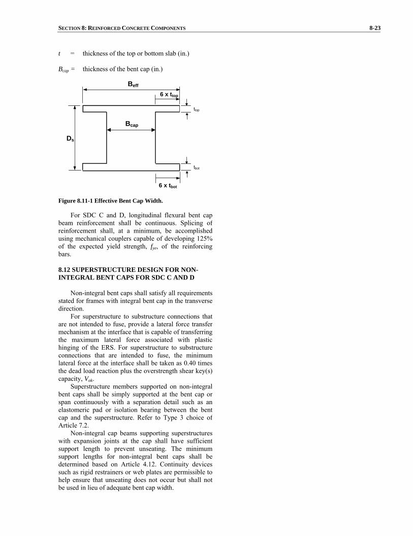
SECTION 8: REINFORCED CONCRETE COMPONENTS 8-23
t = thickness of the top or bottom slab (in.) Bcap = thickness of the bent cap (in.)
Beff
6 x ttop
6 x tbot
Ds
ttop
tbot
Bcap
Figure 8.11-1 Effective Bent Cap Width.
For SDC C and D, longitudinal flexural bent capbeam reinforcement shall be continuous. Splicing ofreinforcement shall, at a minimum, be accomplishedusing mechanical couplers capable of developing 125%of the expected yield strength, fye, of the reinforcing bars.
8.12 SUPERSTRUCTURE DESIGN FOR NON-INTEGRAL BENT CAPS FOR SDC C AND D
Non-integral bent caps shall satisfy all requirements
stated for frames with integral bent cap in the transversedirection.
For superstructure to substructure connections that are not intended to fuse, provide a lateral force transfermechanism at the interface that is capable of transferringthe maximum lateral force associated with plastichinging of the ERS. For superstructure to substructureconnections that are intended to fuse, the minimumlateral force at the interface shall be taken as 0.40 timesthe dead load reaction plus the overstrength shear key(s)capacity, Vok.
Superstructure members supported on non-integral bent caps shall be simply supported at the bent cap or span continuously with a separation detail such as anelastomeric pad or isolation bearing between the bent cap and the superstructure. Refer to Type 3 choice ofArticle 7.2.
Non-integral cap beams supporting superstructureswith expansion joints at the cap shall have sufficientsupport length to prevent unseating. The minimumsupport lengths for non-integral bent caps shall bedetermined based on Article 4.12. Continuity devicessuch as rigid restrainers or web plates are permissible tohelp ensure that unseating does not occur but shall notbe used in lieu of adequate bent cap width.
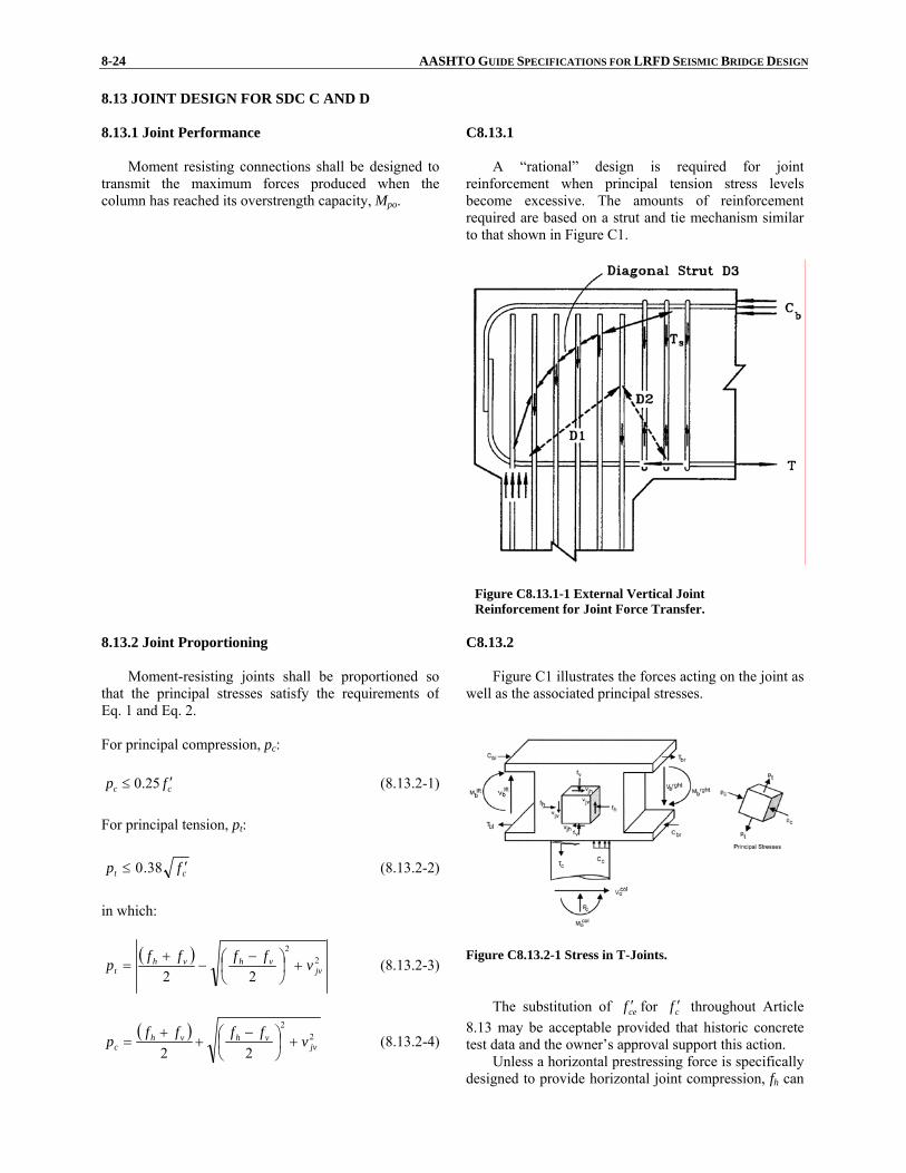
8-24 AASHTO GUIDE SPECIFICATIONS FOR LRFD SEISMIC BRIDGE DESIGN 8.13 JOINT DESIGN FOR SDC C AND D 8.13.1 Joint Performance
Moment resisting connections shall be designed totransmit the maximum forces produced when the column has reached its overstrength capacity, Mpo.
C8.13.1
A “rational” design is required for joint reinforcement when principal tension stress levels become excessive. The amounts of reinforcement required are based on a strut and tie mechanism similar to that shown in Figure C1.
Figure C8.13.1-1 External Vertical Joint
Reinforcement for Joint Force Transfer. 8.13.2 Joint Proportioning
Moment-resisting joints shall be proportioned so
that the principal stresses satisfy the requirements ofEq. 1 and Eq. 2.
For principal compression, pc:
cc fp ′≤ 25.0 (8.13.2-1) For principal tension, pt:
ct fp ′≤ 38.0 (8.13.2-2)
in which:
( ) 22
22 jvvhvh
t vffffp +⎟⎠⎞
⎜⎝⎛ −
−+
= (8.13.2-3)
( ) 22
22 jvvhvh
c vffffp +⎟⎠⎞
⎜⎝⎛ −
++
= (8.13.2-4)
C8.13.2 Figure C1 illustrates the forces acting on the joint as
well as the associated principal stresses.
Figure C8.13.2-1 Stress in T-Joints. The substitution of cef ′ for cf ′ throughout Article
8.13 may be acceptable provided that historic concrete test data and the owner’s approval support this action.
Unless a horizontal prestressing force is specifically designed to provide horizontal joint compression, fh can

SECTION 8: REINFORCED CONCRETE COMPONENTS 8-25
jv
cjv A
Tv = (8.13.2-5)
capacjv BlA = (8.13.2-6)
jh
cv A
Pf = (8.13.2-7)
( ) capscjh BDDA += (8.13.2-8)
scap
bh DB
Pf = (8.13.2-9)
hM
T poc = (8.13.2-10)
where: Bcap = bent cap width (in.) Dc = cross sectional dimension of column in the
direction of bending (in.) Ds = depth of superstructure at the bent cap for
integral joints or depth of cap beam for non-integral bent caps (in.)
lac = length of column reinforcement embedded into
the bent cap (in.) Pc = column axial force including the effects of
overturning (kip) Pb = beam axial force at the center of the joint
including the effects of prestressing and theshear associated with plastic hinging (kip)
h = distance from the center of gravity of the
tensile force to the center of gravity of thecompressive force of the column section (in.)
Tc = column tensile force associated with the
column overstrength plastic hinging moment,Mpo (kip)
Mpo = overstrength plastic moment capacity of
column determined in accordance with Article8.5 (kip-in.)
In lieu of Eq. 10, Tc can be obtained directly from
the moment-curvature analysis.
typically be ignored without significantly impacting the principle stress calculation.
8.13.3 Minimum Joint Shear Reinforcing
Provide the transverse reinforcement in the form of

8-26 AASHTO GUIDE SPECIFICATIONS FOR LRFD SEISMIC BRIDGE DESIGN tied column reinforcement, spirals, hoops, orintersecting spirals or hoops. The joint shearreinforcement can also be provided in the form ofcolumn transverse steel or exterior transversereinforcement continued into the bent cap.
If the principal tension stress in the joint, pt, as defined in Article 8.13.2 is less than '11.0 cf , then the transverse reinforcement in the joint, ρs, shall satisfy Eq.1 and no additional reinforcement within the joint isrequired.
yh
cs f
f '11.0≥ρ (8.13.3-1)
where: fyh = nominal yield stress of transverse reinforcing
(ksi)
'cf = nominal concrete compressive strength (ksi)
ρs = volumetric reinforcement ratio of transverse
reinforcing provided within the cap as definedby Eq. 8.6.2-6
If the principal tension stress in the joint, pt, is
greater than '11.0 cf , then transverse reinforcement inthe joint, ρs, shall satisfy Eq. 2 and additional jointreinforcement is required as indicated in Article 8.13.4for integral bent cap beams or Article 8.13.5 for non-integral bent cap beams.
240.0ac
sts l
A≥ρ (8.13.3-2)
where: Ast = total area of column reinforcement anchored in
the joint (in.2) lac = length of column reinforcement embedded into
the bent cap (in.) For interlocking cores, ρs shall be based on the total
area of reinforcement of each core. 8.13.4 Integral Bent Cap Joint Shear Design
8.13.4.1 Joint Description
The following types of joints are considered “T”joints for joint shear analysis:
• Integral interior joints of multi-column
C8.13.4.1
The design of beam-column joints is based upon research and experiments for circular columns framing into rectangular beams. Although no specific requirements have been developed for rectangular
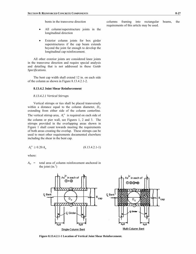
SECTION 8: REINFORCED CONCRETE COMPONENTS 8-27
bents in the transverse direction
• All column/superstructure joints in thelongitudinal direction
• Exterior column joints for box girder
superstructures if the cap beam extendsbeyond the joint far enough to develop thelongitudinal cap reinforcement.
All other exterior joints are considered knee joints
in the transverse direction and require special analysisand detailing that is not addressed in these Guide Specifications.
The bent cap width shall extend 12 in. on each side
of the column as shown in Figure 8.13.4.2.1-2.
columns framing into rectangular beams, the requirements of this article may be used.
8.13.4.2 Joint Shear Reinforcement
8.13.4.2.1 Vertical Stirrups
Vertical stirrups or ties shall be placed transversely
within a distance equal to the column diameter, Dc, extending from either side of the column centerline. The vertical stirrup area, jv
sA is required on each side ofthe column or pier wall, see Figures 1, 2 and 3. Thestirrups provided in the overlapping areas shown inFigure 1 shall count towards meeting the requirementsof both areas creating the overlap. These stirrups can beused to meet other requirements documented elsewhere including the shear in the bent cap.
stjv
s AA 20.0≥ (8.13.4.2.1-1) where: Ast = total area of column reinforcement anchored in
the joint (in.2)
Figure 8.13.4.2.1-1 Location of Vertical Joint Shear Reinforcement.

8-28 AASHTO GUIDE SPECIFICATIONS FOR LRFD SEISMIC BRIDGE DESIGN
Figure 8.13.4.2.1-2 Joint Shear Reinforcement Details.
Figure 8.13.4.2.1-3 Location of Horizontal Joint Shear Reinforcement.

SECTION 8: REINFORCED CONCRETE COMPONENTS 8-29
8.13.4.2.2 Horizontal Stirrups
Horizontal stirrups or ties shall be placedtransversely around the vertical stirrups or ties in two ormore intermediate layers spaced vertically at not morethan 18 in. The horizontal reinforcement, jh
sA , shall be placed within a distance Dc from each side of thecolumn centerline as shown in Figure 8.13.4.2.1-3.
stjh
s AA 10.0≥ (8.13.4.2.2-1) where: Ast = total area of column reinforcement anchored in
the joint (in.2)
8.13.4.2.3 Horizontal Side Reinforcement
The total longitudinal side face reinforcement in the
bent cap shall be at least equal to the greater of the areasspecified in Eq. 1 and shall be placed near the side facesof the bent cap with a maximum spacing of 12 in. asshown in Figure 8.13.4.2.1-2. Any side reinforcementplaced to meet other requirements shall count towardsmeeting the requirement of this article.
⎪⎩
⎪⎨
⎧
≥botcap
topcap
sfs
A
AA
10.0
10.0max (8.13.4.2.3-1)
where:
sfsA = area of longitudinal side reinforcement in the
bent cap (in.2)
topcapA = area of bent cap top flexural steel (in.2)
botcapA = area of bent cap bottom flexural steel (in.2)
8.13.4.2.4 J-Bars For integral cap of bents skewed greater than 20o,
vertical J-bars hooked around the longitudinal top decksteel extending alternatively 24 in. and 30 in. into thebent cap are required. The J-dowel reinforcement shall satisfy:
stbarj
s AA 08.0≥− (8.13.4.2.4-1) The J-bars shall be placed within a rectangular
region defined by the width of the bent cap and thedistance Dc on either side of the centerline of thecolumn, see Figure 1 and Figure 8.13.4.2.1-3.
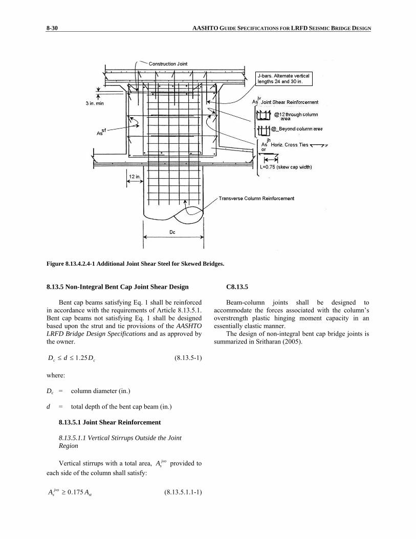
8-30 AASHTO GUIDE SPECIFICATIONS FOR LRFD SEISMIC BRIDGE DESIGN
Figure 8.13.4.2.4-1 Additional Joint Shear Steel for Skewed Bridges. 8.13.5 Non-Integral Bent Cap Joint Shear Design
Bent cap beams satisfying Eq. 1 shall be reinforced
in accordance with the requirements of Article 8.13.5.1.Bent cap beams not satisfying Eq. 1 shall be designedbased upon the strut and tie provisions of the AASHTOLRFD Bridge Design Specifications and as approved bythe owner.
cc DdD 25.1≤≤ (8.13.5-1) where: Dc = column diameter (in.) d = total depth of the bent cap beam (in.)
C8.13.5
Beam-column joints shall be designed to accommodate the forces associated with the column’s overstrength plastic hinging moment capacity in an essentially elastic manner.
The design of non-integral bent cap bridge joints is summarized in Sritharan (2005).
8.13.5.1 Joint Shear Reinforcement 8.13.5.1.1 Vertical Stirrups Outside the Joint Region Vertical stirrups with a total area, jvo
sA provided to each side of the column shall satisfy:
stjvo
s AA 175.0≥ (8.13.5.1.1-1)

SECTION 8: REINFORCED CONCRETE COMPONENTS 8-31
where: Ast = total area of column reinforcement anchored in
the joint (in2) Vertical stirrups or ties shall be placed transversely
within a distance equal to the column diameter, Dc, extending from each face of the column as shown inFigure 1 and Figure 2. The area of these stirrups shallnot be used to meet other requirements such as shear inthe bent cap.
Figure 8.13.5.1.1-1 Joint Shear Reinforcement Details.

8-32 AASHTO GUIDE SPECIFICATIONS FOR LRFD SEISMIC BRIDGE DESIGN
Figure 8.13.5.1.1-2 Location of Vertical Joint Shear Reinforcement.
8.13.5.1.2 Vertical Stirrups Inside the Joint Region Vertical stirrups with a total area, jvi
sA , spaced evenly over the column shall satisfy:
stjvi
s AA 135.0≥ (8.13.5.1.2-1) where: Ast = total area of column reinforcement anchored in
the joint (in2)
8.13.5.1.3 Additional Longitudinal Cap Beam Reinforcement Longitudinal reinforcement, jl
sA , in both the topand bottom faces of the cap beam, is required in additionto that which is required to resist other loads. Theadditional area of the longitudinal steel shall satisfy:
stjl
s AA 245.0≥ (8.13.5.1.3-1) where: Ast = total area of column reinforcement anchored in
the joint (in2)
8.13.5.1.4 Horizontal J-Bars Horizontal J-bars hooked around the longitudinal
SECTION 8: REINFORCED CONCRETE COMPONENTS 8-33
reinforcement on each face of the cap beam are requiredas shown in Figure 8.13.5.1.1-1. At a minimum, locatehorizontal J-bars at every other vertical to longitudinalbar intersection within the joint. The J-dowel reinforcement bar shall be at least a #4 size bar.
8.14 COLUMN FLARES FOR SDC C AND D 8.14.1 Horizontally Isolated Flares
The preferred method for detailing flares is tohorizontally isolate the top of flared sections from thesoffit of the cap beam. Isolating the flare allows theflexural hinge to form at the top of the column, thusminimizing the seismic shear demand on the column.
A horizontal gap isolating the flare from the capbeam shall extend over the entire cross section of theflare excluding a core region equivalent to the prismatic column cross section. For SDC C, a minimum gapthickness of 4 in. shall be used.
For SDC D the gap shall be large enough so that itwill not close during a seismic event. The gap thicknessshall be the largest of:
• 1.5 times the calculated plastic rotation demand from the pushover analysis times the distancefrom the center of the column to the extreme edge of the flare
• 4 in.
The added mass and stiffness of the isolated flare
can typically be ignored in the dynamic analysis.
8.14.2 Integral Column Flares
Column flares that are integrally connected to thebent cap should be avoided whenever possible. Lightly reinforced integral flares should only be used whenrequired for service load design or aesthetic considerations and are permitted for SDC A and B. Theflare geometry should be kept as slender as possible.
The higher plastic hinging forces shall beconsidered in the design of the column, superstructure and footing.
C8.14.2 Test results have shown that slender lightly
reinforced flares perform adequately after cracking has developed in the flare concrete, essentially separating the flare from the confined column core. However,integral flares require higher shear forces and moments to form the plastic hinge at the top of the column compared to isolated flares.
8.14.3 Flare Reinforcement
Column flares shall be nominally reinforced outside the confined column core to prevent the flare concretefrom completely separating from the column at highductility levels.
The reinforcement ratio for the transversereinforcement, outside of the column core, that confinesthe flared region shall be 0.0045 for the upper third ofthe flare and 0.00075 for the bottom two-thirds of the flare.
The minimum longitudinal reinforcement within theflare shall be equivalent to #5 bars at 12 in. spacing.

8-34 AASHTO GUIDE SPECIFICATIONS FOR LRFD SEISMIC BRIDGE DESIGN
8.15 COLUMN SHEAR KEY DESIGN FOR SDC C AND D
Column shear keys shall be designed for the axial
and shear forces associated with the column’soverstrength moment capacity, Mpo, including the effectsof overturning. The key reinforcement shall be locatedas close to the center of the column as possible tominimize developing a force couple within the keyreinforcement.
Steel pipe sections can be used in lieu of reinforcing steel to relieve congestion and reduce the momentgenerated within the key.
Moment generated by the key reinforcing steelshould be considered in applying capacity designprinciples.
8.16 CONCRETE PILES
8.16.1 Transverse Reinforcement Requirements
For SDC C or D where piles are not designed ascapacity protected members (i.e., piles, pile shafts, pileextensions where plastic hinging is allowed in soft soil Eor F, liquefaction case), the upper portion of every pileshall be reinforced and confined as a potential plastichinge region as specified in Article 4.11. The shearreinforcement requirements specified in Article 8.6 shallapply. If an analysis of the bridge and pile system indicates that a plastic hinge can form at a lower level,the plastic hinge region shall extend 3D below the pointof maximum moment, and the requirements mentionedabove shall apply.
8.16.2 Cast-In-Place and Precast Concrete Piles
For cast-in-place and precast concrete piles,longitudinal steel shall be provided for the full length ofthe pile. In the upper two-thirds of the pile, thelongitudinal steel ratio shall not be less than 0.007.Longitudinal reinforcement shall be provided by not lessthan four bars.
For piles where a permanent steel casing is used, the extent of longitudinal reinforcement can be reduced toonly the upper portion of the pile required to developultimate tension and compression capacities of the pile.

REFERENCES R-1
REFERENCES
AASHTO, 1999, Guide Specifications for Seismic Isolation Design. 2nd Edition. Washington, DC: American Association of State Highway and Transportation Officials. AASHTO. 2002. Standard Specifications for Highway Bridges and Interim Specifications, 17th Edition, HB-17. American Association of State Highway and Transportation Officials, Washington, DC. AASHTO. 2004. LRFD Bridge Design Specifications and Interim Specifications. 3rd Edition, LRFDUS-3-I2. American Association of State Highway and Transportation Officials, Washington, DC. AASHTO. 2007. LRFD Bridge Design Specifications, 4th Ed., American Association of State Highway and Transportation Officials, Washington, DC. AASHTO/AWS D1.5M/D1.5. 2002. Bridge Welding Code. American National Standard/American Association of State Highway and Transportation Officials/American Welding Society, Washington, DC. Abrahamson, N.A., 1992, “Non-stationary Spectral Matching Program,” Seismological Research Letters, v. 63, no.1, p.30. AISC. 1992. Seismic Provisions for Structural Steel Buildings. American Institute of Steel Construction, Chicago, IL. AISC. 1993. Load and Resistance Factor Design Specification for Structural Steel Buildings. 2nd Edition. American Institute of Steel Construction, Chicago, IL. AISC. 1994. Manual of Steel Construction - Load and Resistance Factor Design. 2nd Edition. American Institute of Steel Construction, Chicago, IL. AISC. 1997. Seismic Provisions for Structural Steel Building. American Institute of Steel Construction, Chicago, IL. AISC. (1999b). Seismic Provisions for Structural Steel Buildings (2005) Supplement No. 1 American Institute of Steel Construction, Chicago, IL. Alfawahkiri, F., 1997, Cyclic Testing of Concrete-Filled Circular Tubes, Thesis presented in partial fulfillment for the degree of Master of Applied Sciences, Dept. of civil Engineering, University of Ottawa, Ottawa, Ontario, Canada. Applied Technology Council (ATC). 1996. Improved Seismic Design Criteria for California Bridges: Provisional Recommendations. Report ATC-32, Redwood City, CA Aschheim, M., and J. P. Moehle. Shear Strength and Deformability of RC Bridge Columns Subjected to Inelastic Cyclic Displacements. Report UCB/EERC 92/04, Earthquake Engineering Research Center, University of California, Berkeley, CA, March 1992. Astaneh, A. A., Goel, S. C., and Hanson, R. D. (1986). "Earthquake-resistant Design of Double Angle Bracings," Engineering Journal, AISC, 23(4). Astaneh-Asl, A., Shen, J.H., and Cho, S.W., 1993, “Seismic Performance and Design Consideration in Steel Bridges”, Proceedings of the 1st US Seminar on Seismic Evaluation and Retrofit of Steel Bridges, San Francisco, California. Astaneh-Asl, A., Bolt, B., Mcmullin, K.M., Donikian, R. R., Modjtahedi, D., and Cho, S. W., 1994, Seismic Performance of Steel Bridges During the 1994 Northridge Earthquake, UCB report CE-STEEL 94/01, University of California at Berkeley. Astaneh-Asl, A., and Roberts, J., 1996, Proceedings of the 2nd US Seminar on Seismic Evaluation and Retrofit of Steel Bridges, San Francisco, Report No. UCB/CEE-Steel-96/09, Department of Civil and Environmental Engineering, University of California at Berkeley. Astaneh, A. A. (1998). "Seismic Behavior and Design of Gusset Plate," Steel Tips, Structural Steel

R-2 AASHTO GUIDE SPECIFICATIONS FOR LRFD SEISMIC BRIDGE DESIGN Education Council, Moraga, CA. ATC, 1981, Seismic Design Guidelines for Highway Bridges, ATC-6 Report, Applied Technology council, Redwood City, California. ATC, 1993, Proceedings of Seminar on Seismic Isolation, Passive Energy Dissipation, and Active Control, ATC-17-1 Report, Applied Technology Council, Redwood City, California. ATC and BSSC, 1997, Applied Technology Council and Building Seismic Safety Council, NEHRP Guidelins for the Seismic Rehabilitation of Buildings, Federal Emergency Management Agency Report FEMA-273. Azizinamini, A., Shahrooz, B., El-Remaily, A., and Astaneh, H., 1999, “Chapter 10: Connections to Composite Members,” Handbook of structural Steel Connection Design and Details, McGraw-Hill, New York. Ballard, T. A., Krimotat, A., Mutobe, R., and Treyger, S., 1996, “Non-linear Seismic Analysis of Carquinez Strait bridge,” Proceedings of the 2nd U.S. Seminar on Seismic Design, Evaluation and Retrofit of Steel Bridges, San Francisco, Report No. UCB/CEE-Steel-96/09, Department of Civil Engineering, University of California, Berkeley, pp. 359-368. Berry, M. and M. O. Eberhrnd. Estimating Flexural Damage in Reinforced Concrete Columns. Pacific Earthquake Engineering Research Center (PEER), University of California, Berkeley, CA August 2003. Billings, I.J., Kennedy, D.W., Beamish, M.J., Jury, R., Marsh, J., 1996, “Auckland Harbour Bridge Seismic Assessment”, Proceedings of the 2nd U.S. Seminar on Seismic Design, Evaluation and Retrofit of Steel Bridges, San Francisco, Report No. UCB/CEE-Steel-96/09, Department of Civil Engineering, University of California, Berkeley, pp. 275-293. Bolt, B.A., and Gregor, N.J., 1993, Synthesized Strong Ground Motions for the Seismic Condition Assessment of the Eastern Portion of the San Francisco Bay Bridge, Earthquake Engineering Research Center, Berkeley, Report UCB/EERC-93.12, University of California at Berkeley. BSSC, 1995, 1994 Edition NEHRP Recommended Provisions for Seismic Regulations for New Buildings, Reports FEMA-222a and FEMA-223A, prepared by the Building Seismic Safety Council for the Federal Emergency Management Agency, Washington, D.C. BSSC, 1998, 1997 Edition NEHRP Recommended Provisions for Seismic Regulations for New Buildings and Other Structures, FEMA-302 and FEMA-303 Reports, prepared by the Building Seismic Safety Council for the Federal Emergency Management Agency, Washington, D.C. Bruneau, M., Wilson, J.W., and Tremblay, R. 1996, “Performance of Steel Bridges During the 1995 Hyogoken-Nanbu (Kobe, Japan) Earthquake”, Canadian Journal of Civil Engineering, Vol. 23, No. 3, pp. 678-713. Bruneau, M., Uang., C.M., and Whittaker, A, 1997, Ductile Design of Steel Structures, McGraw-Hill, New York, NY, 480 pages. Bruneau, M., and Marson, J., 1999, Cyclic Testing of Concrete-Filled Circular Steel Tube Bridge Column Having Encased Fixed Based Detail, Report OCEERC-99-22, Ottawa Carleton Earthquake Engineering Research Centre, Ottawa, Ontario, Canada. Buckle, I.G., Mayes, R.L., and Button, M.R., 1987, Seismic Design and Retrofit Manual for Highway Bridges, Report FHWA-IP-87-6, Federal Highway Administration, Washington, D.C., 312 pp. Button, M.R., Cronin, C.J., and Mayes, R.L., 1999, Effect of Vertical Ground Motions on the Structural Response of Highway Bridges, Technical Report MCEER-99-0007, State University of New York at Buffalo. Caltrans. (1995a). Bridge Memo to Designers Manual, California Department of Transportation, Sacramento, CA. Caltrans. (1995b). Bridge Design Aids Manual, California Department of Transportation,Sacramento, CA.

REFERENCES R-3 Caltrans. (1997). San Francisco-Oakland Bay Bridge West Spans Seismic Retrofit Design Criteria, Final Draft, California Department of Transportation, Sacramento, CA. Caltrans. (1999). Memo to Designers 20-1 Seismic Design Methodology, California Department of Transportation, Sacramento, CA. Caltrans. (2000a). Bridge Design Specifications, California Department of Transportation,Sacramento, CA. Caltrans. 2001. Guide Specifications for Seismic Design of Steel Bridges. 1st Edition. California Department of Transportation, Sacramento, CA, December 2001. Caltrans. (2006). Seismic Design Criteria Version 1.4. California Department of Transportation, Sacramento, CA, December. Carden, L., Garcia-Alvarez, S., Itani, A, and Buckle, I. (2001). “Cyclic Response of Steel Plate Girder Bridges in the Transverse Direction,” The Sixth Caltrans Seismic Research Workshop, Divisions of Engineering Services, California Department of Transportation, Sacramento, CA, June 12-13. Chang, G.A. and Mander, J.B., 1994a, Seismic Energy Based Fatigue Damage Analysis of Bridge Columns: Part I – Evaluation of Seismic Capacity, Technical Report NCEER-94-0006, National Center for Earthquake Engineering Research, State University of New York at Buffalo, New York. Chang, G.A. and Mander, J.B., 1994b, Seismic Energy Based Fatigue Damage Analysis of Bridge Columns: Part II – Evaluation of Seismic Demand, Technical Report NCEER-94-0013, National Center for Earthquake Engineering Research, State University of New York at Buffalo, New York. CSA, 2001, Limit States Design of Steel Strucutres, Canadian Standards Association, Rexdale, Ontario, Canada. CSABAC, 1999, Seismic Soil-Foundation-Structure Interaction, Final report, Caltrans Seismic Advisory Board Ad Hoc Committee on Soil-Foundation-Structure Interaction (CSABAC), prepared for California Department of Transportation, Sacramento, California. Dameron, R. A., Sobash, V. P., and Parker, D. R., 1995, Seismic Analysis of the Existing San Diego-Coronado Bay Bridge, Report prepared for the California Department of Transportation, Anatech Consulting Engineers, 800 pages. DesRoches, R., and G. Fenves. New design and analysis procedures for intermediate hinges in multiple-frame bridges. Report UCB/EERC 97/12, Earthquake Engineering Research Center, University of California, Berkeley, CA 1997. Dicleli, M., and Bruneau, M., 1995a, “Seismic Performance of Multispan Simply Supported Slab-on-Girder Highway Bridges,” Engineering Structures, Vol. 17, No. 1, pp. 4-14. Dicleli, M., and Bruneau, M., 1995b, “Seismic Performance of Simply Supported and Continuous Slab-on-Girder Steel Bridges,” Structural Journal of the American Society of Civil Engineers, Vol. 121, No. 10, pp. 1497-1506. Dietrich, A. M., and Itani, A. M., 1999, Cyclic Behavior of Laced and Perforated Members on the San Francisco-Oakland Bay Bridge, Center for Civil Engineering Earthquake Research, Report No. CCER-99-09, University of Nevada, Reno, 194 pp. Donikian, R., Luo, S., Alhuraibi, M., Coke, C., Williams, M., and Swatta, M., 1996, “The Global Analysis Strategy for the Seismic Retrofit Design of the San Rafael and San Mateo Bridges”, Proceedings of the 2nd U. S. Seminar on Seismic Design, Evaluation and Retrofit of Steel Bridges, Report No. UCB/CEE-Steel-96/09, Department of Civil and Environmental Engineering, University of California at Berkeley, pp. 405-415. EERI, 1990, “Loma Prieta Earthquake Reconnaissance Report,” Earthquake Spectra, Supplement to Vol. 6, Earthquake Engineering Research Institute, Oakland California. Frankel, A., C. Mueller, T. Barnhard, D. Perkins, E. V. Leyendecker, N. Dickman, S. Hanson, and M. Hopper (1996). Interim National Seismic Hazard Maps: Documentation. U.S. Geological Survey, January 1996.

R-4 AASHTO GUIDE SPECIFICATIONS FOR LRFD SEISMIC BRIDGE DESIGN Gasparini, D., and Vanmarcke, E. H., 1976, SMIQKE: A Program for Artificial Motion Generation, Department of Civil Engineering, Massachusetts Institute of Technology, Cambridge, MA. Gates et al., 1995, Proceedings of the First National Seismic Conference on Bridges and Highways, San Diego, California. Housner, G.W. (Chairman, Seismic Advisory Board), 1994 “The Continuing Challenge,” Report to the Director, California Department of Transportation on the 1994 Northridge Earthquake, Seismic Advisory Board, Sacramento, California. ICBO, 1997, Uniform Building Code, International Conference of Building Officials, Whittier, California. ICC, 2000, International Building Code, International Code Council, Inc., Birmingham, Alabama. Imbsen, R., Davis, F. V., Chang, G. S., Pecchia, D., and Liu, W. D., 1997, “Seismic Retrofit of I-40 Mississippi River Bridges”, Proceedings of National Seismic Conference on Bridges and Highways-Progress in Research and Practice, Sacramento, California, pp. 457-469. Ingham, T. J., Rodriguez, S., Nader, M. N., Taucer, F., and Seim, C., 1996, “Seismic Retrofit of the Golden Gate Bridge”, Proceedings of the 2nd U. S. Seminar on Seismic Design, Evaluation and Retrofit of Steel Bridges, Report No. UCB/CEE-Steel-96/09, Department of Civil and Environmental Engineering, University of California at Berkeley, pp. 145-164. Itani, A. M. (1997). "Cyclic Behavior of Richmond-San Rafael Tower Links," Report No. CCEER 99-4, Center for Civil Engineering Earthquake Research, University of Nevada, Reno, NV Itani, A. M., Vesco, T. D. and Dietrich, A M. (1998). "Cyclic Behavior of As-Built Laced Members with End Gusset Plates on the San Francisco-Oakland Bay Bridge," Report No. CCEER 98-01, Center for Civil Engineering Earthquake Research, University of Nevada, Reno, NV. Itani, A. M. and Sedarat, H. (2000). “Seismic Analysis and Design of the AISI LRFD Design Examples of Steel Highway Bridges,” Report No. CEER 00-8, Center for Civil Engineering Earthquake Research, University of Nevada, Reno, NV. Jones, M. H., Holloway, L. J., Toan, V., and Hinman, J., 1997, “Seismic Retrofit of the 1927 Carquinez Bridge by a Displacement Capacity Approach”, Proceedings of the National Seismic Conference on Bridges and Highways-Progress in Research and Practice, Sacramento, California, pp. 445-456. Kompfner, T. A., Tognoli, J. W., Dameron, R. A., and Lam, I. P., 1996, “The San Diego-Coronado Bay Bridge Seismic Retrofit Project”, Proceedings of the 2nd U. S. Seminar on Seismic Evaluation and Retrofit of Steel Bridges, Report No. UCB/CEE-Steel-96/09, Department of Civil and Environmental Engineering, University of California at Berkeley, pp. 73-93. Kramer, S. L., 1996, Geotechnical Earthquake Engineering, Prentice Hall, New Jersey. Lam, I. P., Kapuska, M., Chaudhuri, D., 1998, Modeling of Pile Footing and Drilled Shafts for Seismic Design, Technical Report MCEER-98-0018, Multidisciplinary Center for Earthquake Engineering Research, State University of New York at Buffalo, New Your, 117 pp. Lilihanand, K., and Tseng, W. S., 1988, “Development and Application of Realistic Earthquake Time-Histories Compatible with Multiple-Damping Design Spectra,” Proceedings of the 9th World Conference on Earthquake Engineering, Tokyo-Kyoto: Japan Association for Earthquake Disaster Prevention. Mander, J.B., M.J.N. Priestley, and R. Park, "Theoretical Stress-Strain Model for Confined Concrete", Journal of the Structural Division, ASCE, Vol. 114, No. 8, August 1988, pp. 1804-1826. Mander, J.B., M.J.N. Priestley, and R. Park, "Observed Stress-Strain Behavior of Confined Concrete", Journal of the Structural Division, ASCE, Vol. 114, No. 8, August 1988, pp. 1827-1849.

REFERENCES R-5 Mander, J. B., Panthaki, F. D., and Kasalanati, A., 1994, “Low-Cycle Fatigue Behavior of Reinforcing Steel”, ASCE Journal of Materials in Civil Engineering, Vol. 6, No. 4, Nov. 1994, Paper No. 6782, pp. 453-468. Mander, J. B., and Cheng, C-T., 1999, “Replaceable Hinge Detailing for Bridge Columns,” Seismic Response of Concrete Bridges, American Concrete Institute, Special Publication SP-187. Maroney, B., 1996, “Seismic Retrofit of the East Spans of the San Francisco-Oakland Bay Bridge,” Proceedings of the 2nd U. S. Seminar on Seismic Evaluation and Retrofit of Steel Bridges, Report No. UCB/CEE-Steel-96/09, Department of Civil and Environmental Engineering, University of California at Berkeley, pp. 17-34. Martin, G. R., ed., 1994, Proceedings of the 1992 NCEER/SEAOC/BSSC Workshop on Site Response During Earthquakes and Seismic Code Provisions, University of Southern California, Los Angeles, November 18-20, 1992, National Center for Earthquake Engineering Research Special Publication NCEER-94-SP01, Buffalo, New York. Martin, G. R. and R. Dobry, 1994 “Earthquake Site Response and Seismic Code Provisions”, NCEER Bulletin, vol. 8, no. 4, National Center for Earthquake Engineering Research, Buffalo, New York. Martin, G. R., 1998, Development of Liquefaction Mitigation Methodologies: Ground Densification Methods, National Center for Earthquake Engineering Research, Technical Report, Buffalo, New York. McCallen, D. B., and Astaneh-Asl, A., 1996, “Seismic Response of Steel Suspension Bridge,” Proceedings of the 2nd U. S. Seminar on Seismic Evaluation and Retrofit of Steel Bridges, Report No. UCB/CEE-Steel-96/09, Department of Civil and Environmental Engineering, University of California at Berkeley, pp. 335-347. Miranda, E. and Bertero, V., 1994, “Evaluation of Strength Reduction Factors for Earthquake-Resistant Design,” Earthquake Spectra, Vol. 10, No. 2, Earthquake Engineering Research Institute, Oakland, California. NCHRP 12-49 (2001). Recommended LRFD Guidelines for the Seismic Design of Highway Bridges, Part I: Specifications and Part II: Commentary and Appendixes, NCHRP 12-49 Project Team, MCEER, State University of New York at Buffalo, Buffalo, NY. Popov, E. P., Bertero, V. V., and Chandramouli, S., 1975, Hysteretic Behavior of Steel Columns, Earthquake Engineering Research Center Report UCB/EERC-75-11, University of California, Berkeley. Popov, E. P. and Tsai, K. C. (1989). "Performance of Large Seismic Steel Moment Connections under Cyclic Loads," Engrg. J., AISC, 26(2), pp. 51-60. Priestley, M.J.N., and F. Seible, “Seismic Assessment and Retrofit of Bridges”, Structural Systems Research Project, Report SSRP-91/03, University of California San Diego, July 1991. Preistly, M. J. N., F. Seible, and G. M. Calvi. Seismic Design and Retrofit of Bridges. John Wiley and Sons, New York, NY 1996. Prucz, Z., Conway, W. B., Schade, J. E., and Ouyang, Y., 1997, “Seismic Retrofit Concepts and Details for Long-Span Steel Bridges”, Proceedings of National Seismic Conference on Bridges and Highways-Progress in Research and Practice, Sacramento, California, pp. 435-444. Rinne, E.E., 1994, “Development of New Site Coefficient of Building Codes,” Proceedings of the Fifth U.S. National Conference on Earthquake Engineering, Vol. III, pp.69-78, Earthquake Engineering Research Institute, Oakland, California. Roberts, J.E., 1992, “Sharing California’s Seismic Lessons”, Modern Steel Constructions, pp. 32-37. Rodriguez, S., and Ingham, T.J., 1996, “Nonlinear Dynamic Analysis of the Golden Gate Bridge”, Proceeding of the 2nd US Seminar on Seismic Evaluation and Retrofit of Steel Bridges, Report No. UCB/CEE-Steel-96/09, Department of Civil and Environmental Engineering, University of California at Berkeley, pp. 457-466.

R-6 AASHTO GUIDE SPECIFICATIONS FOR LRFD SEISMIC BRIDGE DESIGN SAC, 1995, Interim Guidelines: Evaluation, Repair, Modification and Design of Welded Steel Moment Frame Structures, prepared by the SAC Joint Venture, a partnership of the Structural Engineers Association of California, the Applied Technology Council, and California Universities for Research in Earthquake Engineering, published by the Federal Emergency Management Agency, (FEMA-267 Report), Washington, D.C. SAC, 1997, Interim Guidelines Advisory No. 1 – Supplement to FEMA-267, prepared by the SAC Joint Venture, a partnership of the Structural Engineers Association of California, the Applied Technology Council, and California Universities for Research in Earthquake Engineering, published by the Federal Emergency Management Agency, (FEMA-267A Report), Washington, D.C. SAC, 2000, Recommended Seismic Design Criteria for New Steel Moment-Frame Buildings, prepared by the SAC Joint Venture, a partnership of the Structural Engineers Association of California, the Applied Technology Council, and California Universities for Research in Earthquake Engineering, published by the Federal Emergency Management Agency, (FEMA-350 Report), Washington, D.C. Schamber, R.A., Li, F., Fuller, R.T., and Liu, W.D., 1997, “Seismic Resistance of Steel Bascule Bridges”, Proceedings of National Seismic Conference on Bridges and Highways – Progress in Research and Practice, Sacramento, California, pp. 381-394. Schneider, S.P., Roeder, C.W., and Carpenter, J.E., 1992, “Seismic Behavior of Moment-Resisting Steel Frames: Experimental Study”, ASCE Structural Journal, Vol. 119, No. 6; pp. 1885-1902. Seim, C., Ingham, T. and Rodriguez, S., 1993, “Seismic Performance and Retrofit of the Golden Gate bridge”, Proceedings of the 1st US Seminar on Seismic Evaluation and Retrofit of Steel Bridges, San Francisco, California. Sharma, A.A., Mander, J.B., Blabac, B.B., and Chen, S.S., 2001, Experimental Investigation and Retrofit of Steel Pile Foundations and Pile Bents Under Cyclic Lateral Loading, Technical Report, Multidisciplinary Center for Earthquake Engineering Research, University at Buffalo, Buffalo, New York. Sherman, D.R., 1976, Tentative Criteria For Structural Applications Of Steel Tubing and Pipe, American Iron and Steel Institute, Washington, D.C. Shinozuka, M., Saxena, V., and Deodatis, G., 1999, Effect of Spatial Variation of Ground Motion on Highway Structures, Draft Final Report for MCEER Higheay Project, Submitted to Multidisciplinary Center for Earthquake Engineering Research, University at Buffalo, Buffalo, New York. Shirolé, A. M., and Malik, A. H., 1993, “Seismic Retrofitting of Bridges in New York State”, Proceedings, Symposium on Practical Solutions for Bridge Strengthening & Rehabilitation, Iowa State Univ., Ames, Iowa, pp. 123-131. Silva, W., and Lee, K., 1987, “State-of-the-Art for Assessing Earthquake Hazards in the United State: Report 24,” WES RASCAL Code for Synthesizing Earthquake Ground Motions, Miscellaneous Paper 5-73-1, U. S. Army Engineer Waterways Experiment Station, Vicksburg, Mississippi. Silva, W., 1997, “Characteristics of Vertical Strong Ground Motions for Applications to Engineering Design, Proceedings of the FHWA/NCEER Workshop on the National Representation of Seismic Ground Motions for New and Existing Highway Facilities, National Center for Earthquake Engineering Research, Buffalo, New York, Technical Report NCEER-97-0010, State University of New York at Buffalo, pp. 205-252. Somerville, P.G., 1997, “The Characteristics and Quantification of Near Fault Ground Motion,” Proceedings of the FHWA/NCEER Workshop on the National Representation of Seismic Ground Motion for New and Existing Highway Facilities, Center for Earthquake engineering Research, Buffalo, New York, Technical Report 97-0010, State University of New York at Buffalo, pp. 1293-1318. Somerville, P. G., Smith, N. G., Graves, R. W., and Abrahamson, N. A., 1997, “Modification of Empirical Strong Ground Motion Attenuation Relations to Include the Amplitude and Duration Effects of Rupture Directivity,” Seismological Research Letters, Vol. 68, pp. 199-222.

REFERENCES R-7 Somerville, P., Krawinkler, H., and Alavi, B., 1999, Development of Improved Ground Motion Representation and Design Procedures for Near-Fault Ground Motion, prepared for California Strong Motion Instrumentation Program, California Division of Mines and Geology, Sacramento, California, Draft. South Carolina Department of Transportation. Seismic Design Specifications for Highway Bridges. 1st. Edition. 2001, with October 2002 Interim Revisions. Sritharan, S., "Improved Seismic Design Procedure for Concrete Bridge Joints", Journal of the Structural Engineering, ASCE, Vol. 131, No. 9, September 2005, pp. 1334-1344. Tang, X. and Goel, S. C., 1987, Seismic Analysis and Design Considerations of Braced Steel Structures, Report No. UMCE 87-4, Department of Civil Engineering, University of Michigan, Ann Arbor, Michigan. Uang, C. M., and Bertero, V. V., 1986, Earthquake Simulation Tests and Associated Studies of a 0.3-Scale Model of a Six-Story Concentrically Braced Steel Structure, Report No. UCB/EERC-86/10, Earthquake Engineering Research Center, University of California, Berkeley. Uang, C. M., Tsai, K. C., and Bruneau, M., 2000, “Seismic Design of Steel Bridges”, Bridge Engineering Handbook, (Ed. W.F. Chen, L. Duan), CRC Press, Boca Raton, Florida, pp. 39-1 to 39-34. Uang, C. M., Bruneau, M., Whittaker, A. S., and Tsai, K. C., 2001, “Seismic Design of Steel Structures,” Seismic Design Handbook, (Ed. Naeim), Kluwer Academic Publishers, Norwell, Massachusetts, pp. 409-462. U. S. Army Corp of Engineers, 2000, Time History Dynamic Analysis of Concrete Hydraulic Structures, USACE Engineering Circular EC1110-2-6051. Vincent, J., Abrahamson, T., O’Sullivan, M., Lim, K., Dameron, R., and Donikian, R., 1997, “Analysis and Design for the Inelastic Response of a Major Steel Bridge,” Proceedings of the 2nd National Conference on Bridges and Highways, Sacramento, California, pp. 541-555. Whitmore, R. E. (1952). "Experimental Investigation of Stresses in Gusset Plates," Bulletin 16, University of Tennessee, Knoxville, TN. Zahrai, S. M. and Bruneau, M. (1998). "Impact of Diaphragms on Seismic Responses of Straight Slab-on-Girder Steel Bridges," J. Struct. Engrg. 124(8), pp. 938-947. Zahrai, S. M. and Bruneau, M. (1999). "Ductile End-Diaphragms for Seismic Retrofit of Slab-on-Girder Steel Bridges," J. Struct. Engrg. 125(1), pp. 71-80.


APPENDIX A: FOUNDATION ROCKING ANALYSIS A-1
APPENDIX A
FOUNDATION ROCKING ANALYSIS
Transient foundation uplift, or Foundation Rocking, involving separation of the foundation from the subsoil, is permitted under seismic loading, provided that foundation soils are not susceptible to loss of strength under the imposed cyclic loading. The displacement, or drift ∆T ,as shown in Figure A1, shall be calculated based on the flexibility of the column in addition to the effect of the footing rocking mechanism. For multi-column bents with monolithic connections to the substructure, the effect of rocking shall be examined on the overturning and framing configuration of the subject bent.
For the longitudinal response, multi-column bents that are not monolithic to the superstructure shall be treated similar to a single column bent.
Rocking displacement demands shall be calculated with due consideration of the dynamics of the bridge system or frame. The tributary inertial weight and articulation and/or restraint of other elements of the frame shall be incorporated into the analysis. Some adjustment of the following equations, which were derived for an individual single-column bent, may be required.
For the case of a single column bent or a multi-column bent without a monolithic connection to the superstructure, the footing is considered to be supported on a rigid perfectly plastic soil with uniform compressive capacity pb. The overturning and rocking on the foundation can be simplified using a linear force-deflection relationship as outlined in the following procedure:
• Guess the displacement ∆ or consider a displacement ∆ corresponding to a fixed base analysis.
• Calculate the applied force F at the superstructure level based on Rocking Equilibrium shown in Figure A1. From Statics:
r
sr
FT H
WH
aLWF Δ
−−
=2
)( (A-1)
in which:
)( br
T
pBW
a = (A-2)
• Calculate the equivalent system stiffness:
Δ
=FK r (A-3)
• Calculate the period “T” of the bent system based on Kr and Ws.
• Recalculate ∆ considering 10% damping; this would typically reduce the spectral acceleration ordinates Sa of a
5% damped spectrum by approximately 20%.
)8.0(4 2
2
aST⎟⎟⎠
⎞⎜⎜⎝
⎛
π=Δ (A-4)
where: ∆ is referred to as the total displacement on top of the column (ft.) Sa is the spectral acceleration (ft./sec.2 )
• Iterate until convergence, otherwise the bent is shown to be unstable.

A-2 AASHTO GUIDE SPECIFICATIONS FOR LRFD SEISMIC BRIDGE DESIGN
• Once a converging solution is reached, the local ductility term μ can be calculated in order to ensure the column adequacy where rocking mechanism is not mobilized.
ycolΔΔ
=μ (A-5)
where: ∆ycol = column idealized yield displacement
For soil cover greater than 3 ft., the effect of soil passive resistance needs to be included in the rocking equilibrium of
forces. The design of a column on spread footing system shall follow the steps identified on the flowchart shown on Figure
A2. The restoring moment Mr is calculated as follows:
⎟⎟⎠
⎞⎜⎜⎝
⎛ −=
2aL
WM FTr (A-6)
For the case where, Mo ≥ 1.5Mr, the column shear capacity shall be determined based on Article 8.6 following SDC B
requirements. The column shear demand shall be determined based on 1.5Mr moment demand. For the case where, Mr ≥ Mo, forces based on column plastic hinging shall be considered; the column shear capacity
shall be determined based on Article 8.6 following SDC D requirements. For all other cases, the column shall be designed for P-∆ requirements based on rocking analysis as well as column plastic hinging shear capacity requirements considering a fixed based analysis and following Article 8.6 SDC C requirements.
The shear component of loading should not be included during the overturning check; i.e., a de-coupled approach should be used in treating the two loads. Experience has shown that combining the horizontal load and moment in simplified bearing capacity equations can result in unreasonably sized footings for seismic loading.
Unfactored resistance is used for the moment capacity check for two reasons: (1) the potential for the design seismic load is very small, and (2) the peak load will occur for only a short duration. The distribution and magnitude of bearing stress, as well as liftoff of the footing, are limited to control settlement of the footing from the cycles of load.
Non-triangular stress distributions or greater than 50% liftoff are allowed if analysis can show that soil settlement from cyclic shakedown does not exceed amounts that result in damage to the bridge or unacceptable movement of the roadway surface. By limiting stress distribution and the liftoff to the specified criteria, the amount of shakedown will normally be small under normal seismic loading conditions.
This work was derived based on that presented by Priestley et al. (1996).

APPENDIX A: FOUNDATION ROCKING ANALYSIS A-3
Figure A-1 Rocking Equilibrium of a Single Column Bent.
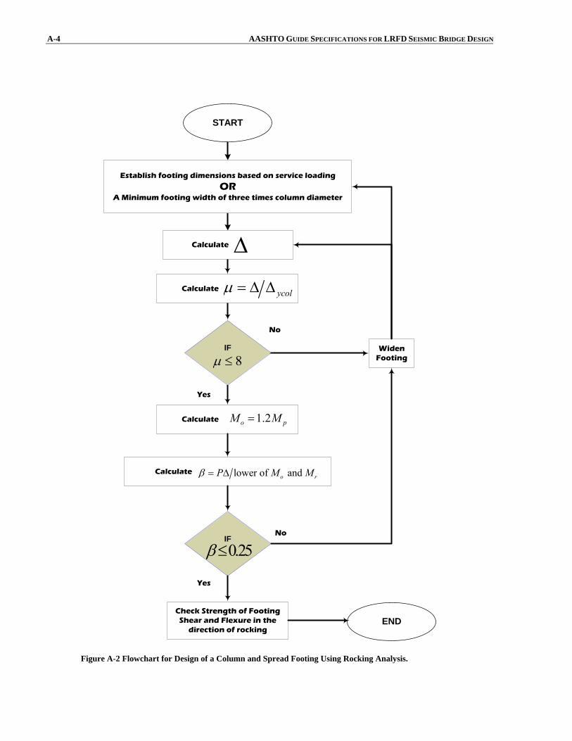
A-4 AASHTO GUIDE SPECIFICATIONS FOR LRFD SEISMIC BRIDGE DESIGN
No
Yes
Establish footing dimensions based on service loading
ORA Minimum footing width of three times column diameter
START
Calculate Δ
Calculate ycolμ = Δ Δ
Calculate 1.2o pM M=
IF
8μ ≤
Calculate lower of and o rP M Mβ = Δ
IF
0.25β≤No
Yes
Check Strength of FootingShear and Flexure in the
direction of rockingEND
WidenFooting
Figure A-2 Flowchart for Design of a Column and Spread Footing Using Rocking Analysis.