Embed Size (px)
Citation preview
2006 Oct. 19 DES Project -- Vaidas Simaitis, University of Illinois 1
DHE – Detector Head Electronics
Monsoon 80mm
Crate Heat Load
2006 Oct. 19 DES Project -- Vaidas Simaitis, University of Illinois 2
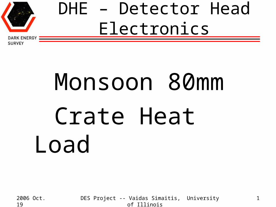
Crate Parts
HEAT EXCHANGER on CHILLER PLENUM (one at each end of main MONSOON cards)
92mm FAN (x2) on FAN PLENUM (one at each end of transition cards)
TRANSITION CARDS (8) (6U x 80mm)
MONSOON CARDS (10) plug in on this side (6U x 160mm Eurocards)
60mm FAN (x2) on MAIN PLENUM (at both ends, only this end shown here)
FAN power supply is in the middle (at both ends)
HEAT EXCHANGERS connect in series with ¼” copper tube
2006 Oct. 19 DES Project -- Vaidas Simaitis, University of Illinois 3
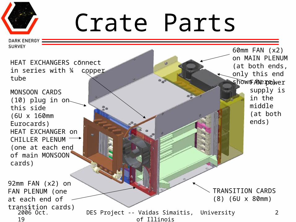
Crate (without shield)
VICOR power supply with built-in 80mm fan, 30cfm listed, pressure drop unknown (x2)
MAIN PLENUM
POWER SUPPLY PLENUM
2006 Oct. 19 DES Project -- Vaidas Simaitis, University of Illinois 4
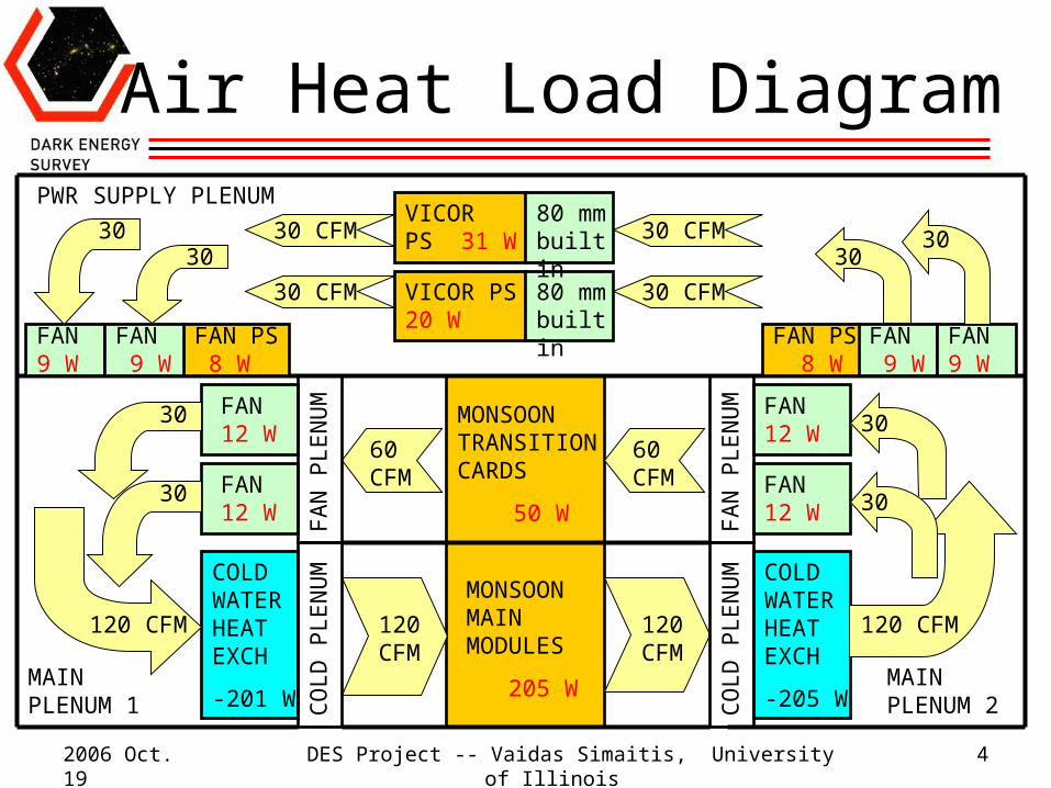
Air Heat Load Diagram
MONSOON TRANSITION CARDS
50 W
MONSOON MAIN MODULES
205 W
COLD WATER HEAT EXCH
-205 W
COLD WATER HEAT EXCH
-201 W
FAN 12 W
FAN 12 W
FAN 12 W
FAN 12 W
VICOR PS 31 W
VICOR PS 20 W
120 CFM120 CFM
60 CFM
60 CFM
30 CFM
30
30
FAN 9 W
FAN 9 W
FAN PS 8 W
FAN PS 8 W
FAN 9 W
FAN 9 W
80 mm built in
80 mm built in
120 CFM
CO
LD
PL
EN
UM
FA
N P
LE
NU
M
FA
N P
LE
NU
M
CO
LD
PL
EN
UM
3030
30 CFM
30 CFM
30 CFM
3030
30
30
120 CFM
MAIN PLENUM 1
MAIN PLENUM 2
PWR SUPPLY PLENUM
2006 Oct. 19 DES Project -- Vaidas Simaitis, University of Illinois 5
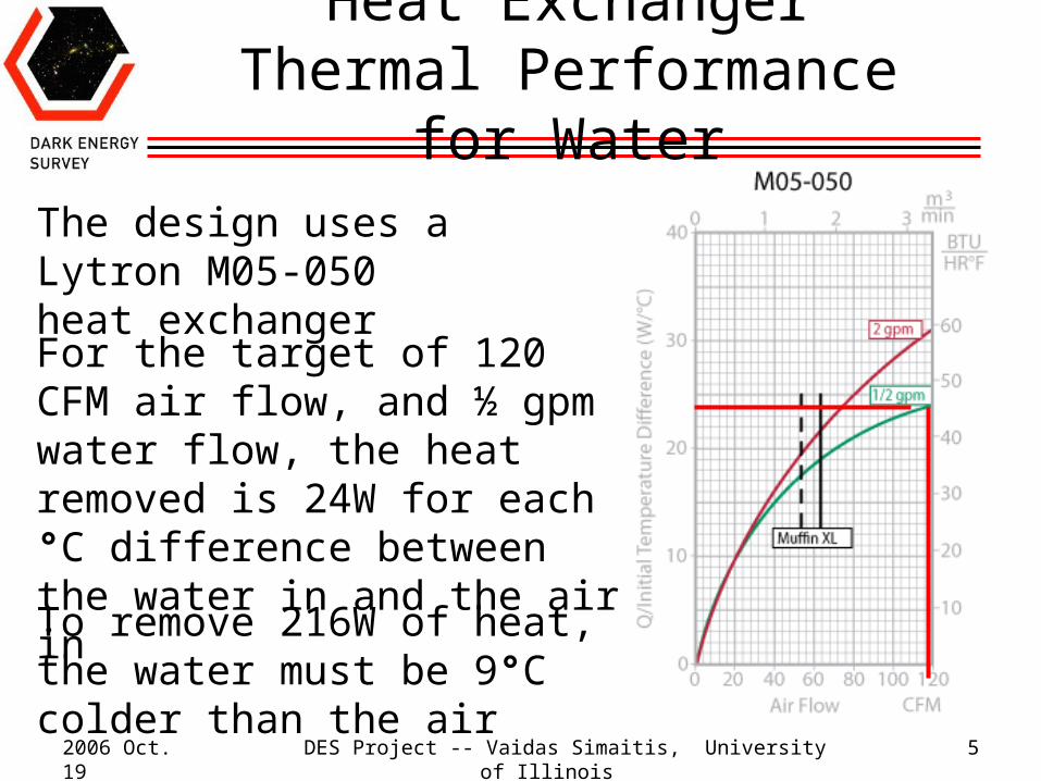
Heat Exchanger Thermal Performance for Water
For the target of 120 CFM air flow, and ½ gpm water flow, the heat removed is 24W for each °C difference between the water in and the air in
The design uses a Lytron M05-050 heat exchanger
To remove 216W of heat, the water must be 9°C colder than the air
2006 Oct. 19 DES Project -- Vaidas Simaitis, University of Illinois 6
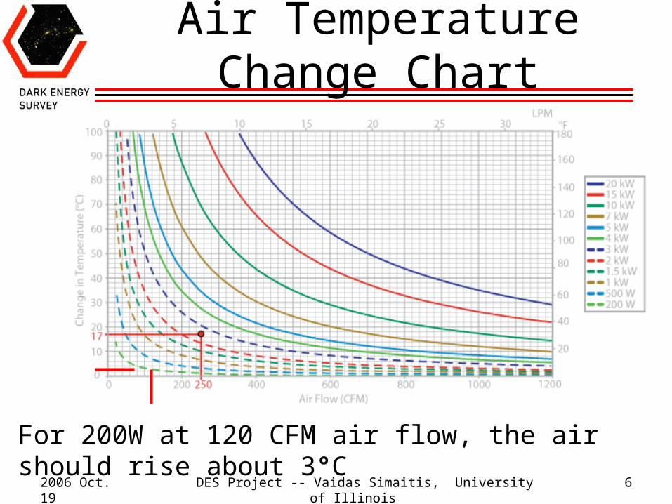
Air Temperature Change Chart
For 200W at 120 CFM air flow, the air should rise about 3°C
2006 Oct. 19 DES Project -- Vaidas Simaitis, University of Illinois 7
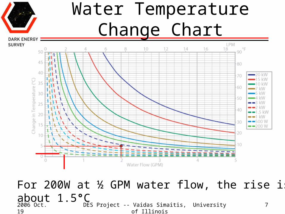
Water Temperature Change Chart
For 200W at ½ GPM water flow, the rise is about 1.5°C
2006 Oct. 19 DES Project -- Vaidas Simaitis, University of Illinois 8
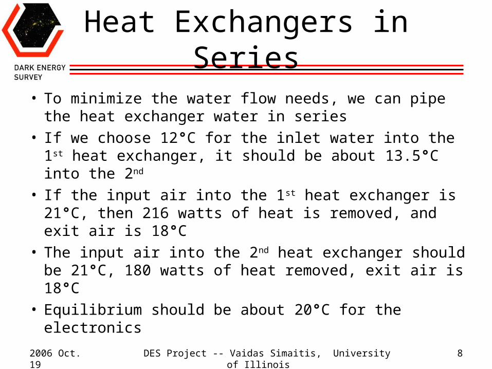
Heat Exchangers in Series
• To minimize the water flow needs, we can pipe the heat exchanger water in series
• If we choose 12°C for the inlet water into the 1st heat exchanger, it should be about 13.5°C into the 2nd
• If the input air into the 1st heat exchanger is 21°C, then 216 watts of heat is removed, and exit air is 18°C
• The input air into the 2nd heat exchanger should be 21°C, 180 watts of heat removed, exit air is 18°C
• Equilibrium should be about 20°C for the electronics
2006 Oct. 19 DES Project -- Vaidas Simaitis, University of Illinois 9
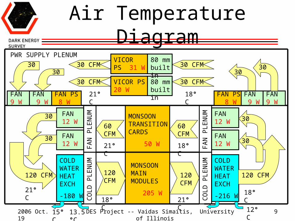
Air Temperature Diagram
MONSOON TRANSITION CARDS
50 W
MONSOON MAIN MODULES
205 W
COLD WATER HEAT EXCH
-216 W
COLD WATER HEAT EXCH
-180 W
FAN 12 W
FAN 12 W
FAN 12 W
FAN 12 W
VICOR PS 31 W
VICOR PS 20 W
120 CFM120 CFM
60 CFM
60 CFM
30 CFM
30
30
FAN 9 W
FAN 9 W
FAN PS 8 W
FAN PS 8 W
FAN 9 W
FAN 9 W
80 mm built in
80 mm built in
120 CFM
CO
LD
PL
EN
UM
FA
N P
LE
NU
M
FA
N P
LE
NU
M
CO
LD
PL
EN
UM
3030
30 CFM
30 CFM
30 CFM
3030
30
30
120 CFM
PWR SUPPLY PLENUM
12°C13.5°C15°C
21°C
18°C 21°C18°C
18°C21°C
18°C21°C
2006 Oct. 19 DES Project -- Vaidas Simaitis, University of Illinois 10
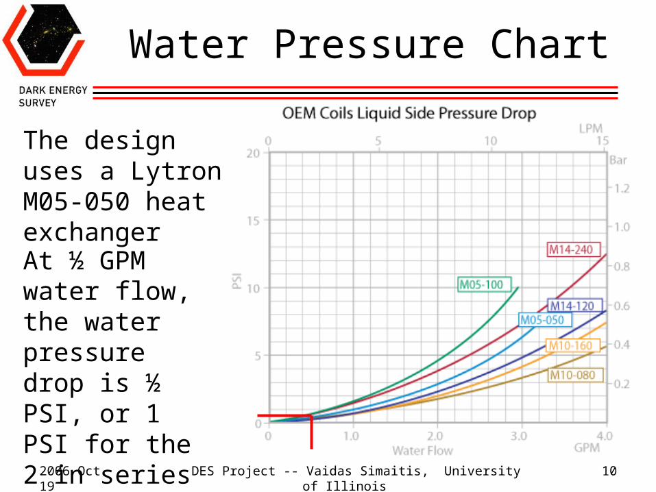
Water Pressure Chart
At ½ GPM water flow, the water pressure drop is ½ PSI, or 1 PSI for the 2 in series
The design uses a Lytron M05-050 heat exchanger
2006 Oct. 19 DES Project -- Vaidas Simaitis, University of Illinois 11
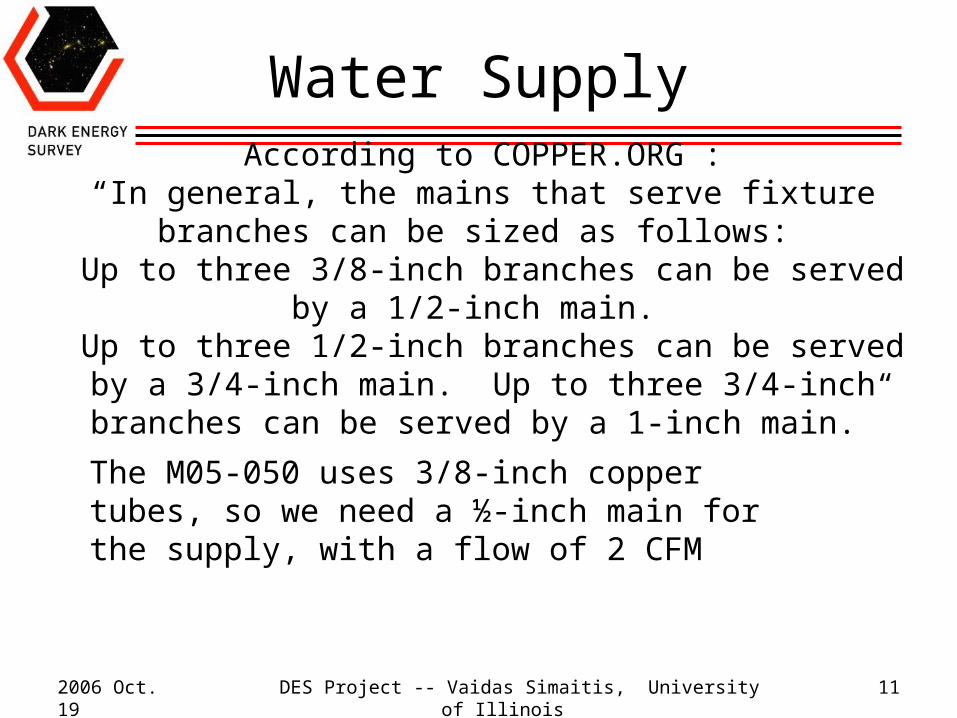
Water Supply
According to COPPER.ORG :“In general, the mains that serve fixture branches can be sized as
follows: Up to three 3/8-inch branches can be served by a 1/2-inch main. Up to three 1/2-inch branches can be served by a 3/4-inch main. Up to three 3/4-inch branches can be served by a 1-inch main.”
The M05-050 uses 3/8-inch copper tubes, so we need a ½-inch main for the supply, with a flow of 2 CFM
2006 Oct. 19 DES Project -- Vaidas Simaitis, University of Illinois 12
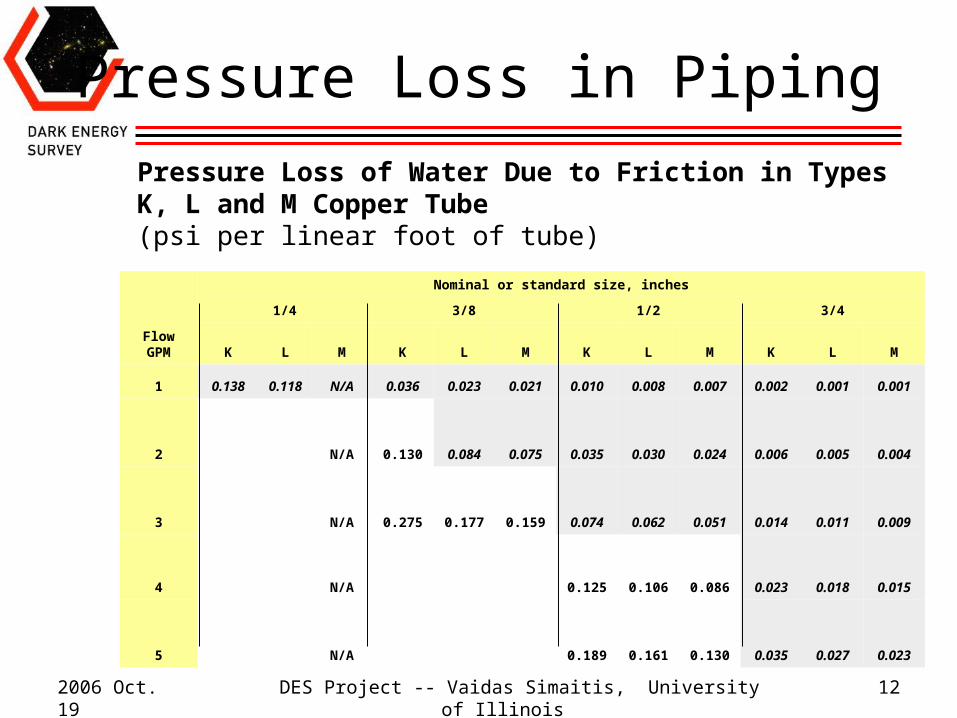
Pressure Loss in Piping
Pressure Loss of Water Due to Friction in Types K, L and M Copper Tube (psi per linear foot of tube)
FlowGPM
Nominal or standard size, inches
1/4 3/8 1/2 3/4
K L M K L M K L M K L M
1 0.138 0.118 N/A 0.036 0.023 0.021 0.010 0.008 0.007 0.002 0.001 0.001
2 N/A 0.130 0.084 0.075 0.035 0.030 0.024 0.006 0.005 0.004
3 N/A 0.275 0.177 0.159 0.074 0.062 0.051 0.014 0.011 0.009
4 N/A 0.125 0.106 0.086 0.023 0.018 0.015
5 N/A 0.189 0.161 0.130 0.035 0.027 0.023
2006 Oct. 19 DES Project -- Vaidas Simaitis, University of Illinois 13
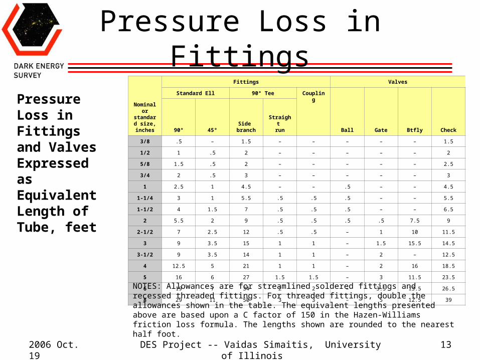
Pressure Loss in Fittings
Pressure Loss in Fittings and Valves Expressed as Equivalent Length of Tube, feet
Nominal or
standard size,
inches
Fittings Valves
Standard Ell 90° Tee Coupling
Ball Gate Btfly Check90° 45°Side
branchStraight
run
3/8 .5 – 1.5 – – – – – 1.5
1/2 1 .5 2 – – – – – 2
5/8 1.5 .5 2 – – – – – 2.5
3/4 2 .5 3 – – – – – 3
1 2.5 1 4.5 – – .5 – – 4.5
1-1/4 3 1 5.5 .5 .5 .5 – – 5.5
1-1/2 4 1.5 7 .5 .5 .5 – – 6.5
2 5.5 2 9 .5 .5 .5 .5 7.5 9
2-1/2 7 2.5 12 .5 .5 – 1 10 11.5
3 9 3.5 15 1 1 – 1.5 15.5 14.5
3-1/2 9 3.5 14 1 1 – 2 – 12.5
4 12.5 5 21 1 1 – 2 16 18.5
5 16 6 27 1.5 1.5 – 3 11.5 23.5
6 19 7 34 2 2 – 3.5 13.5 26.5
8 29 11 50 3 3 – 5 12.5 39NOTES: Allowances are for streamlined soldered fittings and recessed threaded fittings. For threaded fittings, double the allowances shown in the table. The equivalent lengths presented above are based upon a C factor of 150 in the Hazen-Williams friction loss formula. The lengths shown are rounded to the nearest half foot.
2006 Oct. 19 DES Project -- Vaidas Simaitis, University of Illinois 14
Pressure Loss for Gravity
Pressure will be lost in lifting the water to the highest point in the system.
To account for this, multiply the elevation of the highest point, in feet, by the factor 0.434, the pressure exerted by a 1-foot column of water.
This will give the pressure in psi needed to raise the water to that level.
For DES, the difference in height of about 40 feet reduces the available pressure by 18 psi (40 x 0.434 = 17.36).
2006 Oct. 19 DES Project -- Vaidas Simaitis, University of Illinois 15
Pressure Loss Total
Approximately 10 3/8” elbows and connectors per heat exchanger is equivalent of 5 ft. of tubing. This is only about a 0.2 psi loss, but allow 1.0 psi.
The camera is at least 40 feet from the ground, so allow about 100 feet of 1/2” tubing (each way) to the refrigeration unit. This is about a 7.0 psi loss, but recalculate for 3/8” tubing to allow for thicker walls, so use 26 psi.
The pressure loss from gravity is 18 psi. (But may be recovered on the return trip?)
Worst case loss should be about 45 psi.
2006 Oct. 19 DES Project -- Vaidas Simaitis, University of Illinois 16
CONCLUSION
• The calculations above are for water, but we will need a water-alcohol mixture to avoid freezing.
• We will need a refrigeration unit which can dissipate 1500 W at a flow of 2 GPM and output 45psi at 10°C.