Embed Size (px)
Citation preview
2005 Academic Challenge
ENGINEERING GRAPHICS TEST - STATE FINALS
Engineering Graphics Test Production Team Ryan Brown, Illinois State University – Author/Team Coordinator
Kevin Devine, Illinois State University – Author Jacob Borgerson, University of Illinois at Urbana - Champaign – Reviewer
Don Wayman, WYSE – Coordinator of Test Production
GENERAL DIRECTIONS Please read the following instructions carefully. This is a timed test; any instructions from the test supervisor should be followed promptly. The test supervisor will give instructions for filling in any necessary information on the answer sheet. Some Academic Challenge test sites may use answer sheets that require you to fill in the letter of the answer you choose on the blank line after each question number. Others will ask you to indicate your answer to each question by marking an oval that corresponds to the correct answer for that question. Only one oval should be marked to answer each question. Multiple ovals will automatically be graded as an incorrect answer. Be sure ovals are marked as . Not as , , , etc. Test Question - 1. Which of the following was formed by the New Madrid Earthquakes of 1811-1812?
a. Lake of the Ozarks (MO) b. Little Grassy Lake (IL) c. Kentucky Lake (KY) d. Reelfoot Lake (TN) e. Crater Lake (OR) Answer Sheet - 1. If you wish to change an answer, erase your first mark completely before marking your new choice. You are advised to use your time effectively and to work as rapidly as you can without losing accuracy. Do not waste your time on questions that are too difficult for you. Go on to the other questions and come back to the difficult ones later if you can.
*** TIME: 40 MINUTES ***
DO NOT OPEN TEST BOOKLET UNTIL YOU ARE TOLD TO DO SO!
© 2005 Worldwide Youth in Science and Engineering
“WYSE”, “Worldwide Youth in Science and Engineering” and the “WYSE Design” are service marks of and this work is Copyright © 2005 Board of Trustees of the University of Illinois at Urbana - Champaign. All rights reserved.
B C EA

2005 State Finals
WYSE – “Academic Challenge” Engineering Graphics Test (State Finals) – 2005
1. What operation is performed by the
machining bit illustrated below?
A. Spotface
B. Keyway
C. Broach
D. Countersink
E. Counterbore
2. What is the MMC of the hole in the
illustration below?
A. .007
B. .057
C. .490
D. .500
E. .550
3. On most CAD systems, the polar coordinate system uses 0° as the horizontal angle, drawing to the right. What two values could be specified to draw a line that heads toward 10 o’clock, 15 degrees above horizontal?
A. -165 or 75
B. 165 or -195
C. 195 or 15
D. 75 or -175
E. -115 or 15
4. A bolt circle has a diameter of 3.25”, and is the circle of centers for 10 equally spaced holes. The first hole is 7° above horizontal near 3 o’clock. How many degrees are there between holes?
A. -17°
B. 10°
C. 17°
D. 30°
E. 36°
5. In solid modeling, “intersection” is a:
A. Curve editing technique
B. Primitive
C. Sweep feature
D. Boolean operation
E. Mating condition

2005 State Finals
6. The development of a cone requires an
arc as the stretchout line, or baseline. What other object also requires a single arc as the stretchout line?
A. Cube
B. Sphere
C. Pyramid
D. Cylinder
E. Circle-to-rectangle transitional piece
7. A theoretically perfect feature that serves as a reference for dimensions and tolerances:
A. Datum
B. Feature control frame
C. Tolerance
D. Allowance
E. Modifier
8. Behind every drawing of an object is a space relationship involving four imaginary things: 1) the observer’s eye, or station point; 2) the object; 3) ______; and 4) the projectors, also called lines of sight.
A. drafting tools
B. the plane of projection
C. wireframe diagrams
D. a vanishing point
E. drafting standards
Engineering Graphics – 2 9. What operation is specified by the
symbol below?
A. Spotface
B. Fillet weld
C. Broach
D. Surface quality
E. Brazing
10. Select a TRUE phrase with respect to the number of decimal places used when dimensioning a 1” distance on a part.
A. Number of places has no influence on the dimension (i.e. 1.0 = 1.00 = 1.000)
B. Always different for metric drawings than inch drawings (mm-2 places; inch-3 places)
C. Different for drawings that incorporate GD&T (distance has a box around it, and always has 3 places)
D. Should have the same number of places as all the other dimensions of that part
E. Has a major impact on the level of precision the machinist and quality inspector must use, and often determines the tolerance for that dimension

2005 State Finals
11. What is a FALSE interpretation of the
cap screw drawing below?
A. Bolt is unfinished
B. Thread is represented in the simplified method
C. Bolt body is chamfered
D. Bolt is a “hex head”
E. Bolt head is chamfered
Engineering Graphics – 3
12. For the descriptive geometry problem below, select the proper view that would be projected onto the horizontal plane:

2005 State Finals
13. Examine the illustration of the inscribed pentagon below. How many degrees are in angle COE?
A. 60°
B. 72°
C. 100°
D. 120°
E. 144°
14. What do the following words have in common: flatness, cylindricity, runout, and concentricity?
A. GD&T controls
B. Lathe terms
C. Surface quality categories
D. Terms used in cast parts
E. Types of welds
15. What would be an appropriate caption for the illustration below?
A. Assembly process chart
B. Bill of material
C. Tabular dimensioning
D. Revision block
E. Spotface list
Engineering Graphics – 4
16. What is one thing that can be determined about the threaded shaft simply by looking at this detailed representation?
A. It is a metric thread.
B. The pitch is .125”.
C. It is a right-hand thread.
D. The major diameter is 1”.
E. The class of fit is 2.
17. Which of the following is NOT standardized by the ASME?
A. Dimensioning practices
B. Multiview drawing practices
C. Line conventions and lettering
D. CAD command syntax
E. Tolerancing practices
18. Since an oblique surface does not appear as a line in any of the three regular views, a ____________ auxiliary view must be projected that shows the surface as a line, and then a _________ auxiliary view can be projected next from that view.
A. full; half
B. partial; complete
C. primary; secondary
D. sectional; cavalier
E. reference; regular

2005 State Finals
19. Which of the following can be determined for certain by looking at the sectional view below?
A. Object is cylindrical
B. Hole is a threaded hole
C. Object is made of brass
D. Rim of the hole is chamfered
E. Hole features a keyway
20. What is the minimum number of dimensions required to completely dimension the part illustrated below?
A. 7
B. 8
C. 9
D. 10
E. 11
21. How many line segments are needed to create an isometric drawing of a cube?
A. 7
B. 8
C. 9
D. 10
E. 11
Engineering Graphics – 5 22. Given that a flat planar surface is
perpendicular to the frontal projection plane, select a statement that describes the relationship of the surface with the horizontal projection plane:
A. Will be perpendicular to
B. Will be inclined with
C. Will be parallel with
D. Could be either A or B, but not C
E. Could be either A, B, or C
23. With what feature would the local note illustrated below be associated?
A. Spotface on a surface
B. Keyway in a hole
C. Broached hole
D. Countersunk hole
E. Counterbored hole
24. The principles of projection are explained with three planes, frontal, horizontal, and profile. Which two dimensions are projected onto the profile plane?
A. Height and Width
B. Width and Length
C. Depth and Height
D. Width and Depth
E. Height and Length

2005 State Finals
25. For the object illustrated below, if the front view features the true shape and size of surface L, then what view would feature the true size and shape of surface P?
A. Right side view
B. Top view
C. Primary auxiliary view projected from front view
D. Primary auxiliary view projected from top view
E. Secondary auxiliary view projected from primary described in answer C above
26. Identify the type of pictorial drawing illustrated below:
A. 1-point perspective
B. 2-point perspective
C. Isometric
D. Dimetric
E. Oblique
Engineering Graphics – 6
27. In ASME Y14.3M-1994, section 4 is entitled conventional representation, which is defined as deviations from true orthographic projection that are generally recognized and accepted. What is the conventional practice associated with the illustration below?
A. Hole intersection is small enough
that true projection can be ignored.
B. Rib did not need section lines.
C. Fillets and rounds did not need to be shown.
D. Rounded edges would not project as a line, but have been shown for clarity.
E. Threads do not need to be shown.
28. Of ALL the surfaces featured in the object illustrated below, how many are “normal” surfaces?
A. 3
B. 4
C. 5
D. 6
E. 7

2005 State Finals
29. Which of the following dimensions is the shortest?
A. .392”
B. 25/64”
C. 13/32”
D. 9.5mm
E. 1.2cm
30. Select a correct revolved section for the view illustrated below:
Engineering Graphics – 7 31. What caption would be appropriate for
the illustration below?
A. Creating a hyperbola
B. Drawing an ogee curve
C. Trammel ellipse layout
D. Construction of a helix
E. Involute of a line
32. What does the local note identify in the part print illustrated below?
A. Pipe thread
B. Spring
C. Welded cap
D. Metric thread
E. Helicoil insert

2005 State Finals
33. Without assuming features are centered, how many additional dimensions will be required to fully dimension the part illustrated below?
A. 0
B. 1
C. 2
D. 3
E. 4
Engineering Graphics – 8
34. At minimum, how many visible and hidden line segments will it take to complete the “missing line problem” below to create a correct multiview drawing?
A. 1
B. 2
C. 3
D. 4
E. 5

2005 State Finals
Engineering Graphics – 9
2005 State Finals
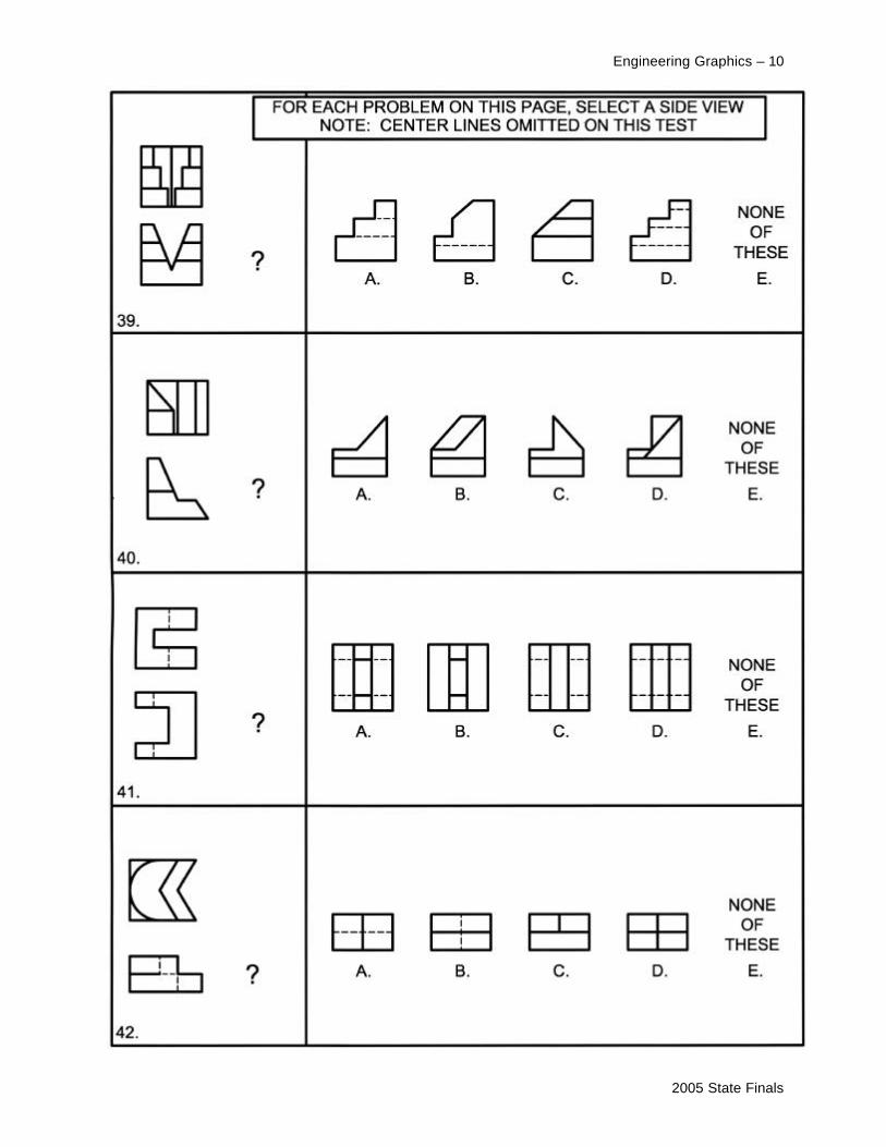
Engineering Graphics – 10

2005 State Finals
Engineering Graphics – 11

2005 State Finals
Engineering Graphics – 12


![[Revision of ASME Y14.3M-1994 (R1999)] MULTIVIEW AND](https://img.pdfslide.us/doc/110x75/61c0d2458935e058c83156d5/revision-of-asme-y143m-1994-r1999-multiview-and-.jpg)