Embed Size (px)
Citation preview

FUSS & O’NEILL LANDFILL CLOSURE2004.0174.H12 HARTFORD, CT
Addendum No. 1
UNDERGROUND DUCTS AND UTILITY STRUCTURES 02584 - 1
SECTION 02584 - UNDERGROUND DUCTS AND UTILITY STRUCTURES
PART 1 - GENERAL
1.1 RELATED DOCUMENTS
A. Drawings and general provisions of the Contract, including General and SupplementaryConditions and Division 1 Specification Sections, apply to this Section.
1.2 SUMMARY
A. This Section includes the following:
1. Ducts in direct-buried duct banks.
2. Handholes and handhole accessories.
B. Related Sections include the following:
1. Division 16 Section "Grounding and Bonding" for grounding electrodes,counterpoise conductors, clamps and connectors for grounding metallic manholeand handhole accessories, and testing of grounds.
1.3 SUBMITTALS
A. Product Data: For the following:
1. Handhole hardware.
2. Conduit and ducts, including elbows, bell ends, bends, fittings, and solvent cement.
3. Duct-bank materials, including spacers and miscellaneous components.
4. Warning tape.
1.4 QUALITY ASSURANCE
A. Electrical Components, Devices, and Accessories including ducts for communications:Listed and labeled as defined in NFPA 70, Article 100, by a testing agency acceptable toauthorities having jurisdiction, and marked for intended use.
B. Comply with ANSI C2.
C. Comply with NFPA 70.
1.5 DELIVERY, STORAGE, AND HANDLING
A. Store nonmetallic ducts with supports to prevent bending, warping, and deforming.

FUSS & O’NEILL LANDFILL CLOSURE2004.0174.H12 HARTFORD, CT
Addendum No. 1
UNDERGROUND DUCTS AND UTILITY STRUCTURES 02584 - 2
B. Store precast concrete units at Project site as recommended by manufacturer to preventphysical damage. Arrange so identification markings are visible.
C. Lift and support precast concrete units only at designated lifting or supporting points.
1.6 PROJECT CONDITIONS
A. Existing Utilities: Do not interrupt utilities serving facilities occupied by Owner or othersunless permitted under the following conditions and then only after arranging to providetemporary utility services according to requirements indicated.
1. Notify Owner at least two days in advance of proposed utility interruptions.
2. Do not proceed with utility interruptions without Owner's written permission.
1.7 COORDINATION
A. Coordinate layout and installation of ducts and handholes with final arrangement of otherutilities and site grading, as determined in the field.
B. Coordinate elevations of ducts and duct-bank entrances into handholes with final profilesof conduits as determined by coordination with other utilities and undergroundobstructions. Revise locations and elevations from those indicated as required to suit fieldconditions and to ensure duct runs drain to handholes, and as approved by Engineer.
PART 2 - PRODUCTS
2.1 PRODUCTS AND MANUFACTURERS
A. Available Manufacturers: Subject to compliance with requirements, manufacturers offeringproducts that may be incorporated into the Work include, but are not limited to, thefollowing:
1. Underground Precast Concrete Utility Structures:
a. Carder Concrete Products.
b. Christy Concrete Products, Inc.
c. Elmhurst-Chicago Stone Co.
d. Riverton Concrete Products.
e. Rotondo Precast/Old Castle.
f. Utility Vault Co.
g. Wausau Concrete Co.
h. Approved Equal
2. Frames and Covers:
FUSS & O’NEILL LANDFILL CLOSURE2004.0174.H12 HARTFORD, CT
Addendum No. 1
UNDERGROUND DUCTS AND UTILITY STRUCTURES 02584 - 3
a. Campbell Foundry Co.
b. East Jordan Iron Works, Inc.
c. McKinley Iron Works, Inc.
d. Neenah Foundry Co.
e. Approved Equal
3. Nonmetallic Ducts and Accessories:
a. Arnco Corp.
b. Beck Manufacturing Inc.
c. Cantex, Inc.
d. Certainteed Corp.; Pipe & Plastics Group.
e. ElecSys, Inc.
f. Electri-Flex Co.
g. Ipex, Inc.
h. Lamson & Sessions; Carlon Electrical Products.
i. Manhattan/CDT/Cole-Flex.
j. Spiraduct/AFC Cable Systems, Inc.
k. Approved Equal
2.2 CONDUIT
A. Conduit and fittings are specified in Division 16 Section "Conduits."
2.3 DUCTS
A. Rigid Nonmetallic Conduit: NEMA TC 2, Type EPC-40-PVC, UL 651, with matchingfittings by the same manufacturer as the conduit, complying with NEMA TC 3 andUL 514B.
B. Rigid Nonmetallic Conduit: NEMA TC 2, Type EPC-80-PVC, UL 651, with matchingfittings by the same manufacturer as the conduit, complying with NEMA TC 3 andUL 514B.
2.4 HANDHOLES
A. Precast Handholes: Reinforced concrete, monolithically poured walls and bottom, withsteel or cast-aluminum frame and access door assembly as the top of handhole. Ductentrances and windows shall be located near corners to facilitate racking. Pulling-in ironsand other built-in items shall be installed before pouring concrete. Cover shall havenonskid finish and legend. Unit, when buried, shall be designed to support AASHTO H20loading.
FUSS & O’NEILL LANDFILL CLOSURE2004.0174.H12 HARTFORD, CT
Addendum No. 1
UNDERGROUND DUCTS AND UTILITY STRUCTURES 02584 - 4
B. Fiberglass Handholes: Molded fiberglass, with 6-inch- square cable entrance at each sideand weatherproof cover with nonskid finish and legend. Unit, when buried, shall bedesigned to support AASHTO H10 loading.
C. Cover Legend: "ELECTRIC" or “COMMUNICATION”.
2.5 ACCESSORIES
A. Duct Spacers: Rigid PVC interlocking spacers, selected to provide minimum duct spacingsand cover depths indicated while supporting ducts during concreting and backfilling;produced by the same manufacturer as the ducts.
2.6 CONSTRUCTION MATERIALS
A. Mortar: Comply with ASTM C 270, Type M, except for quantities less than 2.0 cu. ft.where packaged mix complying with ASTM C 387, Type M, may be used.
B. Brick for Manhole Chimney: Sewer and manhole brick, ASTM C 32, Grade MS.
C. Concrete: Use 3000-psi- minimum, 28-day compressive strength and 3/8-inch maximumaggregate size. Concrete and reinforcement are specified in Division 3 Section "Cast-in-Place Concrete."
PART 3 - EXECUTION
3.1 APPLICATION
A. Underground Ducts for Electrical Feeders: Type EPC-40-PVC, direct-buried duct bank,except use Type EPC-80-PVC when in roadway.
B. Underground Ducts for Communication: Type EPC-40-PVC, direct-buried duct bank,except use Type EPC-80-PVC when in roadway.
C. Handholes: Underground precast concrete utility structures.
3.2 EARTHWORK
A. Excavation and Backfill: Comply with Division 2 Section "Earthwork" but do not useheavy-duty, hydraulic-operated, compaction equipment.
B. Restore surface features at areas disturbed by excavation and reestablish original grades,unless otherwise indicated. Replace removed sod immediately after backfilling iscompleted.
C. Restore all areas disturbed by trenching, storing of dirt, cable laying, and other work.Restore vegetation and include necessary topsoiling, fertilizing, liming, seeding, andmulching. Comply with Division 2 Section "Landscaping."
FUSS & O’NEILL LANDFILL CLOSURE2004.0174.H12 HARTFORD, CT
Addendum No. 1
UNDERGROUND DUCTS AND UTILITY STRUCTURES 02584 - 5
D. Restore disturbed pavement. Refer to Division 2 Section "Bituminous ConcretePavement."
3.3 CONDUIT AND DUCT INSTALLATION
A. Slope: Pitch ducts a minimum slope of 1:300 down toward handholes and away frombuildings and equipment. Slope ducts from a high point in runs between two manholes todrain in both directions.
B. Curves and Bends: Use manufactured elbows for stub-ups at equipment and at buildingentrances. Use manufactured long sweep bends with a minimum radius of 25 feet, bothhorizontally and vertically, at other locations.
C. Use solvent-cement joints in ducts and fittings and make watertight according tomanufacturer's written instructions. Stagger couplings so those of adjacent ducts do not liein the same plane.
D. Duct Entrances to Handholes: Space end bells approximately 10 inches o.c. for 5-inchducts and vary proportionately for other duct sizes. Change from regular spacing to end-bell spacing 10 feet from the end bell without reducing duct line slope and without forminga trap in the line. Grout end bells into manhole walls from both sides to providewatertight entrances.
E. Building Entrances: Make a transition from underground duct to conduit at least 10 feetoutside the building wall. Use fittings manufactured for this purpose. Follow theappropriate installation instructions below:
1. Direct-Buried, Nonencased Ducts at Nonwaterproofed Wall Penetrations: Install aSchedule 40, galvanized steel pipe sleeve for each duct. Calk space between conduitand sleeve with duct-sealing compound on both sides for moisture-tight seal.
F. Direct-Buried Ducts: Support ducts on duct spacers, spaced as recommended bymanufacturer and coordinated with duct size, duct spacing, and outdoor temperature.Install as follows:
1. Separator Installation: Space separators close enough to prevent sagging anddeforming of ducts.
2. Trench Bottom: Continuous, firm, and uniform support for duct bank. Preparetrench bottoms as specified in Division 2 Section "Earthwork" for pipes less than 6inches in nominal diameter.
3. Backfill: Install backfill as specified in Division 2 Section "Earthwork." Afterinstalling first tier of ducts, backfill and compact. Repeat backfilling after placingeach tier. After placing last tier, hand-place backfill to 4 inches over ducts and handtamp. Firmly tamp backfill around ducts to provide maximum supporting strength.Use hand tamper only. After placing controlled backfill over final tier, completebackfilling normally.
FUSS & O’NEILL LANDFILL CLOSURE2004.0174.H12 HARTFORD, CT
Addendum No. 1
UNDERGROUND DUCTS AND UTILITY STRUCTURES 02584 - 6
4. Minimum Clearances between Ducts: 2 inches between ducts for like services and 6inches between power and signal ducts.
5. Depth: Install top of duct bank at least 24 inches below finished grade, unlessotherwise indicated.
G. Warning Tape: Bury warning tape approximately 12 inches above all duct banks. Aligntape parallel to and within 3 inches of the centerline of duct bank.
H. Stub-ups: Use rigid steel conduit for stub-ups to equipment. For equipment mounted onoutdoor concrete bases, extend steel conduit a minimum of 5 feet from edge of base.Install insulated grounding bushings on terminations. Couple steel conduits to ducts withadapters designed for this purpose and encase coupling with 3 inches of concrete.
I. Sealing: Provide temporary closure at terminations of ducts that have cables pulled. Sealspare ducts at terminations. Use sealing compound and plugs to withstand at least 15-psighydrostatic pressure.
J. Pulling Cord: Install 100-lbf- test nylon cord in ducts, including spares.
3.4 HANDHOLE INSTALLATION
A. Elevation: Install handholes with depth as indicated. Where indicated, cast handholecover frame directly into roof of handhole and set roof surface 1 inch above grade.
B. Access: Install frame and cover.
1. Set frames in paved areas and trafficways flush with finished grade. Set other frames1 inch above finished grade.
C. Grounding: Install ground rod through floor in each structure with top protruding 4inches above floor. Ground exposed metal components and hardware with bare-copperground conductors. Train conductors neatly around corners. Use cable clamps securedwith expansion anchors to attach ground conductors.
D. Precast Concrete Handhole Installation: Unless otherwise indicated, comply withASTM C 891.
1. Install units level and plumb and with orientation and depth coordinated withconnecting ducts to minimize bends and deflections required for proper entrances.
2. Unless otherwise indicated, support units on a level bed of crushed stone or gravel,graded from 1-inch sieve to No. 4 sieve and compacted to same density as adjacentundisturbed earth.
3.5 FIELD QUALITY CONTROL
A. Testing: Demonstrate capability and compliance with requirements on completion ofinstallation of underground ducts and utility structures.
FUSS & O’NEILL LANDFILL CLOSURE2004.0174.H12 HARTFORD, CT
Addendum No. 1
UNDERGROUND DUCTS AND UTILITY STRUCTURES 02584 - 7
B. Grounding: Test handhole grounding to ensure electrical continuity of grounding andbonding connections. Measure and report ground resistance as specified in Division 16Section "Grounding and Bonding."
C. Duct Integrity: Pull aluminum or wood test mandrel through duct to prove joint integrityand test for out-of-round duct. Provide mandrel equal to 80 percent fill of the duct. Ifobstructions are indicated, remove obstructions and retest.
3.6 CLEANING
A. Pull leather-washer-type duct cleaner, with graduated washer sizes, through full length ofducts. Follow with rubber duct swab for final cleaning and to assist in spreading lubricantthroughout ducts.
B. Clean internal surfaces of handholes. Remove foreign material.
END OF SECTION

FUSS & O’NEILL LANDFILL CLOSURE2004.0174.H12 HARTFORD, CT
SUMMARY OF WORK - ELECTRICAL 16010-1
SECTION 16010 - SUMMARY OF WORK - ELECTRICAL
PART 1 - GENERAL
1.1 WORK INCLUDED
A. The work provided under Division 16 shall be as specified in Division 16 sections listed inthe table of contents and as indicated on the drawings. In summary and without limitingthe generality thereof, the work shall consist of the following:
1. Basic Materials and Methods
2. Demolition
3. Power Distribution
4. Final connection to existing equipment
B. The Contractor shall be responsible for coordinating the activities of power andcommunication work related to this project with the owner’s representative. The ownershall be informed 48 hours in advance of all power and communication outages. Anyoutage shall not be greater than 24 hours.
C. Electrical Contractor shall provide all temporary power and lighting as required forconstruction activities.
1.2 RELATED WORK
A. The following work shall be performed under other Divisions. Coordinate related workwith the following:
1. Sitework for site utilities
1.3 QUALITY ASSURANCES
A. Only the best of workmanship in accordance with present standards and generally acceptedconstruction practices will be acceptable. Any work installed which the workmanship isjudged by the Engineer to be below the present standards or generally acceptedconstruction practices shall be taken out and replaced with properly done work at theContractor's expense.
1.4 SITE CONDITIONS
A. The Drawings shall be taken in a sense as diagrammatic. Locations of mechanical andelectrical equipment are not intended to show every offset and fitting, nor every structuraldifficulty that may be encountered during the installation of the work. Where necessary andafter approval from the Engineer, the alignment of work and equipment shall be variedfrom that shown on Drawings without extra expense to the Owner.
FUSS & O’NEILL LANDFILL CLOSURE2004.0174.H12 HARTFORD, CT
SUMMARY OF WORK - ELECTRICAL 16010-2
B. Install work as close as possible to layouts shown on Contract Drawings. Modify work asnecessary to:
1. Provide maximum possible headroom and space clearances.
2. Provide ready access to all parts of the work, for inspection, operation, safemaintenance and repair, and code conformance.
3. Coordinate and arrange work to avoid conflicts with work of other trades.Satisfactory space conditions shall be shown on coordination drawing submittals.
4. Where space appears inadequate, consult Engineer before proceeding withinstallation.
C. Finished work shall present a neat coordinated appearance.
1.5 PROJECT CONTROL
A. The Contractor shall ensure no debris from demolition or construction remains at theclose of each workday and that work areas adjacent to the work area are maintained in asafe and useable condition.
1.6 DEFINITIONS
A. The following terms are used in this Division and are defined as follows:
1. "Provide": To furnish and install, ready for safe and regular operation the item,material or service under discussion.
2. "Furnish": To purchase, acquire and deliver to the site, complete with relatedaccessories.
3. "Install": To erect, mount and connect completely, by acceptable methods.
4. "Work": Labor, materials, equipment, apparatus, controls and accessories requiredfor proper and complete installation.
5. "Concealed": Embedded in masonry or other construction; or installed in furredspaces, trenches or crawl spaces; or installed within double partitions or hungceilings; or in enclosures.
6. "Exposed": Visible to building occupants, excluding mechanical room and utilitytunnel locations.
7. "Equal": Of weight, size, design, capacity and efficiency to meet requirementsspecified and shown, and of acceptable manufacture, as determined in the opinion ofthe Engineer.
8. "Acceptable": Acceptable, as determined in the opinion of the Engineer.
9. "Contractor": General Contractor.
10. "Named" Product: Manufacturer's name for product, as recorded in publisheddocuments of latest issue as of date of Contract Documents. Obtain Engineer'spermission before using products of later or earlier model.
FUSS & O’NEILL LANDFILL CLOSURE2004.0174.H12 HARTFORD, CT
SUMMARY OF WORK - ELECTRICAL 16010-3
B. Standards, specifications and tests of following technical societies, organizations andgovernmental bodies, as referenced in Contract Documents, are hereby made part ofContract Documents.
1. IES: Illuminating Engineering Society.
2. NEC: National Electrical Code.
3. ANSI: American National Standards Institute.
4. ASTM: American Society for Testing and Materials.
5. EPA: Environmental Protection Agency.
6. FS: Federal Specification.
7. IEEE: Institute of Electrical and Electronics Engineers.
8. NEMA: National Electrical Manufacturers Association.
9. NFPA: National Fire Protection Association.
10. OSHA: Occupational Safety and Health Administration.
11. UL: Underwriters Laboratories.
12. CODE: Codes and regulations of the Federal, State and local governments and ofutility companies having jurisdiction, as appropriate.
C. Use of a singular or plural reference in these Specifications shall not be construed to limitnumber of units required. These specifications are intended to define quality andperformance characteristics; quantity of units supplied shall be as needed to meetrequirements as specified and as shown on Contract Documents.
PART 2 - PRODUCTS
A. Products provided under Division 16 shall be as specified in the following Sections ofDivision 16 and as indicated on the Drawings.
PART 3 - EXECUTION
3.1 INSTALLATION
A. Installation requirements for the work provided under Division 16 shall be as specified inthe following Sections of Division 16 and as indicated on the Drawings.
END OF SECTION
FUSS & O’NEILL LANDFILL CLOSURE2004.0174.H12 HARTFORD, CT
Addendum No. 1
BASIC MATERIALS AND METHODS - ELECTRICAL 16050-1
SECTION 16050 - BASIC MATERIALS AND METHODS - ELECTRICAL
PART 1 - GENERAL
1.1 WORK INCLUDED
A. Unless otherwise indicated, provide Basic Material and Methods including raceway, wireand cable, pull and junction boxes, outlet boxes, wiring devices, motor starters, disconnectswitches, overcurrent protective devices, electrical equipment not furnished as an integralpart of manufactured equipment, and all incidental devices and accessories necessary forthe complete installation of electrical systems indicated on the Drawings and specified inother Sections of Division 16.
1.2 PERMITS AND FEES
A. The Contractor shall give all necessary notices, obtain all permits, file all required plans,obtain all necessary approvals of governmental departments and utilities having jurisdictionover the electrical work and obtain all required certificates and inspections. If requested inwriting or specified in other Division 16 Sections provide Engineer with copies ofnotification letters, permits, certificates, and inspection reports. The Contractor shall paypermit fees.
1.3 CODES, REGULATIONS AND STANDARDS
A. All materials, equipment, apparatus and work shall be in accordance with the latest editionof the National Electrical Code which has been adopted by the State of Connecticut, Stateand Local codes, and the requirements of the local utility companies.
B. All equipment and material provided under Division 16 shall be approved by theUnderwriters' Laboratories, Inc. or other national, well known testing laboratory asevidenced by listing or labeling. All equipment items or parts thereof shall bear themanufacturer's nameplate, which shall give all pertinent information for the particular item.Distributor's or contractor's nameplates will not be acceptable.
C. Contract Documents shall govern whenever they are more stringent than Coderequirements.
D. Where discrepancies occur between the Specifications and the Drawings, the morestringent rule shall govern. The Contractor shall bring all discrepancies to the Engineer’sattention.
1.4 SUBMITTALS
A. Prepare shop drawing according to paragraphs 1.04 G and 1.04 H and submit through theContractor to the Engineer for review.
FUSS & O’NEILL LANDFILL CLOSURE2004.0174.H12 HARTFORD, CT
Addendum No. 1
BASIC MATERIALS AND METHODS - ELECTRICAL 16050-2
B. The selection and intention to use a product specified by name shall NOT excuse the needfor timely submission of shop drawings for that product.
C. Immediately after award of contract and prior to submitting shop drawings, Contractorshall submit for review a preliminary list of intended or proposed manufacturers for allitems for which shop drawings are required.
D. Submission of shop drawings of unnamed manufacture or shop drawings at variance withthe Contract Documents is NOT a proper request for substitution.
E. Samples that are submitted in lieu of shop drawings shall be clearly identified and shall besubmitted in duplicate. Only one sample will be returned and the accepted sample shall bekept available at the job site office. The accepted sample retained by the Engineer will bekept available at Engineer's home office.
F. Upon completion of shop drawing review, shop drawings will be returned, marked withone of following notations: Furnish as submitted, Furnish as corrected, Revise andResubmit, Rejected, or Submit Specified Item. Only products whose shop drawings aremarked "Furnish as submitted" or "Furnish as corrected" shall be used on the project.
G. Submittals shall clearly indicate the following information:
1. Specification Section and Paragraph under which equipment is specified. (Failure tocomply will result in submittal rejection.)
2. Equipment or fixture identification corresponding to that used in ContractDocuments. (Failure to comply will result in submittal rejection.)
3. Descriptive data necessary to verify compliance with Contract Documents. (Failureto comply will result in submittal rejection.)
4. Manufacturer's specifications including materials of construction, metal gauge,thickness and finish.
5. Certified dimensional drawings including clearances required for maintenance oraccess.
6. Performance data, ratings, operating characteristics and operating limits.
7. Electrical ratings and characteristics.
8. Wiring and control diagrams, where applicable.
9. Certifications requested, including UL label or listing.
H. In addition, submittals shall include the following:
1. Accessories and special/non-standard features and materials which are beingfurnished.
2. List of accessories which are required for a proper installation but are NOT beingprovided by the product manufacturer or are NOT being furnished under this

FUSS & O’NEILL LANDFILL CLOSURE2004.0174.H12 HARTFORD, CT
Addendum No. 1
BASIC MATERIALS AND METHODS - ELECTRICAL 16050-3
Section. In the latter case, identify the Section(s) under which the accessories arebeing furnished.
1.5 PRODUCT SELECTION
A. Contractor's options for selecting products are limited by Contract Documentrequirements and governing regulations and are NOT controlled by industry traditions orprocedures experienced by Contractor on previous construction projects. Requiredprocedures include, but are NOT necessarily limited to, following various methods ofspecifying:
1. "Or Equal": Where named products are accompanied by the term "or equal" orwords of similar effect, provide one of named products or propose substituteproduct according to paragraph 1.06, SUBSTITUTIONS.
2. Standards, Codes and Regulations: Where specification requires only compliancewith a standard, code or regulation, Contractor may select any product whichcomplies with requirements of that standard, code or regulation.
3. Performance Requirements: Provide products which comply with specificperformances indicated and which are recommended by manufacturer (in publishedproduct literature or by individual certification) for application intended. Overallperformance of product is implied where product is specified with only certainspecific performance requirements.
B. Inclusion by name, of more than one manufacturer or fabricator, does NOT necessarilyimply acceptability of standard products of those named. All manufacturers, named orproposed, shall conform, with modification as necessary, to criteria established by ContractDocuments for performance, efficiency, materials and special accessories.
1.6 SUBSTITUTIONS
A. Substitution requests from vendors, suppliers and manufacturers may be submitted onlyduring bid period. Requests for substitution will NOT be considered unless requests arereceived by the Engineer at least 7 days prior to Bid Due date AND all supporting data isprovided such that an adequate review can be performed. If substitution is acceptable, anAddendum will be issued.
B. Substitution request from Contractors may be submitted only after the award of Contract.Requests shall be in writing on Contractor's letterhead and shall include:
1. Contractor's statement to the effect that proposed substitution will result in overallwork equal to or better than, work originally intended.
2. Contractor's detailed comparison of significant qualities between specified item andproposed substitution.
3. Statement of effect on construction time, coordination with other affected work, andcost information or proposal.
FUSS & O’NEILL LANDFILL CLOSURE2004.0174.H12 HARTFORD, CT
Addendum No. 1
BASIC MATERIALS AND METHODS - ELECTRICAL 16050-4
C. Substitution requests from contractors will only be considered if:
1. Extensive revisions to Contract Documents are NOT required;
2. Changes are in keeping with general intent of Contract Documents;
3. Requests are submitted in a timely and proper manner, fully documented; and
4. One or more of following conditions is satisfied; all as judged by Engineer:
a. Where request is directly related to the "or equal" clause or words of similareffect in Contract Documents.
b. Where specified product, material or method can NOT be provided withinContract Time; but NOT as a result of Contractor's failure to pursue the workpromptly to coordinate various activities properly.
c. Where specified product, material or method can NOT be provided in mannerwhich is compatible with other materials of the work and where Contractorcertifies that proposed substitution is compatible.
d. Where specified product, material or method can NOT be properlycoordinated with other materials of the work and where Contractor certifiesthat proposed substitution can be properly coordinated.
e. Where specified product, material or method can NOT be warranted asrequired and where Contractor certifies that proposed substitution can be sowarranted.
f. Where specified product, material or method can NOT be used withoutadversely affecting Owner's insurance coverage on completed work and whereContractor certifies that proposed substitution can be so used.
g. Where specified product, material or method will encounter other substantialnon-compliances which are NOT possible to otherwise overcome except byusing proposed substitution.
h. Where specified product, material or method can NOT receive requiredapproval by governing authority and proposed substitution can be soapproved.
i. Where a substantial advantage is offered to the Owner; in terms of cost, time,energy conservation or other valuable considerations; after deductingoffsetting responsibilities that this Contractor may be required to bear,including additional compensation to Engineer for any redesign or evaluationservices, increased cost of other work by other contractors, and similarconsiderations.
D. The burden is upon the Contractor, supplier and manufacturer to satisfy to the Engineerthat:
1. The proposed substitute is equal to, or superior to, the item specified.
2. The intent of the Contract Documents, including required performance, capacity,efficiency, quality, durability, safety, function, appearance, space clearances anddelivery date, will be equaled or bettered.

FUSS & O’NEILL LANDFILL CLOSURE2004.0174.H12 HARTFORD, CT
Addendum No. 1
BASIC MATERIALS AND METHODS - ELECTRICAL 16050-5
E. Changes in work of other trades, such as structural supports, which are required as a resultof substitution and the associated costs for such changes, shall be the completeresponsibility of the Contractor proposing the substitution. There shall be NO additionalexpense to the Owner.
1.7 SAMPLES
A. Submit samples as requested by Engineer/Owner.
1.8 RECORD DRAWINGS
A. Contractor shall maintain and keep on the job at all times, one complete and separate set ofblackline prints of the Electrical work. As work progresses, all changes, revisions andadditions to Electrical work shall be recorded clearly, neatly, accurately and promptly.
B. Contractor shall indicate daily progress on these prints by coloring in the various lines,fixtures, apparatus and associated appurtenances as they are erected.
C. Approval of requisition for payment of work installed will NOT be given unless supportedby the record prints as required above.
D. At the conclusion of work, Contractor will deliver all record drawings to Owner asrequired by GENERAL CONDITIONS and SUPPLEMENTARY GENERALCONDITIONS.
1.9 OPERATING AND MAINTENANCE MANUALS
A. Contractor shall submit for review, Operating and Maintenance manuals for each systemor piece of equipment, at least 4 weeks prior to request for acceptance of same. Uponacceptance, Contractor will furnish 4 copies of each manual to Engineer for transmittal toOwner. Operating and Maintenance manuals shall be arranged in the following format:
1. Description of Electrical System and Component Parts, including function, normaloperating characteristics and limiting conditions, performance curves, engineeringdata and tests, and complete nomenclature and manufacturer's number forreplaceable parts. (Tab A)
2. Operating Procedures, including start-up, break-in, routine and normal operatinginstructions; regulation, control, stopping, shutdown and emergency instructions;summer and winter operating instructions; and any special operating instructions.(Tab B)
3. Sequence of Operation and Control Diagrams, corrected to show as-built conditions.(Tab C)
4. Copies of approved shop drawings, charts and diagrams. (Tab D)
5. Maintenance Procedures, including routine operations, guide to trouble-shooting;disassembly, repair and reassembly; alignment, adjusting and checking; servicing and
FUSS & O’NEILL LANDFILL CLOSURE2004.0174.H12 HARTFORD, CT
Addendum No. 1
BASIC MATERIALS AND METHODS - ELECTRICAL 16050-6
lubrication schedule, and list of lubricants; manufacturer's installation andmaintenance bulletins and related information. (Tab E)
6. Parts List, including illustrations, assembly drawings and diagrams required formaintenance, predicted life of parts subject to wear, and recommendations forstocking spare parts. (Tab F)
7. Names, addresses and telephone numbers of manufacturer's representative andService Company. (Tab G)
8. Other data, if required under pertinent Sections of these Specifications. (Tab H)
1.10 GUARANTEE
A. Furnish standard manufacturers' guarantees for all work under this Division. Suchguarantees shall be in addition to, and NOT in lieu of, other liabilities under the law or byother provisions of the Contract Documents.
B. Materials, equipment and workmanship shall carry the standard warranty against defects inmaterial and workmanship. Failure which may develop due to defective or impropermaterial, equipment, workmanship or design shall be made good, forthwith, by and at theexpense of the Contractor, including damage done to areas, materials and other systemsresulting from this failure.
C. Guarantee that all elements of the systems are of sufficient capacity to meet the specifiedperformance requirements as set forth in Contract Documents.
D. Upon receipt of notice from Owner of a failure of system(s) or component(s) during theguarantee period, replace affected components within reasonable time period at noadditional cost.
E. Guarantee period shall extend minimum of one year from Date of Acceptance of projectby Owner.
F. Before final request for payment, Contractor shall furnish written guarantee covering theabove requirements.
1.11 EXAMINATION OF SITE AND CONTRACT DOCUMENTS
A. Before submitting prices or beginning work, Contractor must thoroughly examine the siteand the Contract Documents.
B. No claim for extra compensation will be recognized if difficulties are encountered whichwould have been revealed by examination of site conditions and all Contract Documentsprior to executing Contract.
C. Where discrepancies occur within Contract Documents, notify Engineer in writing, ofdiscrepancy and request a clarification. Until notified of Engineer's decision, include itemor arrangement of better quality, greater quantity or higher cost in Contract price.

FUSS & O’NEILL LANDFILL CLOSURE2004.0174.H12 HARTFORD, CT
Addendum No. 1
BASIC MATERIALS AND METHODS - ELECTRICAL 16050-7
D. Notify Engineer, in writing, of all materials and apparatus believed to be omitted,inadequate or unsuitable, or in violation of laws, ordinances, rules or regulations ofauthorities having jurisdiction. In absence of such written notice, it is mutually agreed thatbid price for work performed under each Section has included the cost of any and all itemsrequired for acceptable and satisfactory functioning of the entire system.
1.12 GUARANTEE AND WARRANTY
A. All materials, equipment and labor provided under Division 16 shall be guaranteed againstdefects for a period of one year or as specified in Division 1. Any defects that appearduring the guarantee period shall be corrected at no cost to the Owner. The Electricalcontractor shall provide free maintenance and emergency service including labor andmaterials during the guarantee period.
B. Any item provided under Division 16 that requires excessive servicing during the guaranteeperiod will be considered defective and shall be replaced at no cost to the Owner.
C. A letter of guarantee along with any extended equipment warranty shall be delivered to theOwner before final payment is made.
PART 2 - PRODUCTS
2.1 MATERIALS
A. Basic Materials as specified in Section 16110 through 16199.
B. Materials for systems are specified in Section 16200 through 16999.
C. Materials for work are also specified on the Drawings.
PART 3 - EXECUTION
3.1 INSTALLATION
A. The wiring method shall be copper conductors with 600 volt THWN insulation installed inconcealed EMT conduit unless otherwise shown on the Drawings:
B. All work shall be run concealed wherever possible unless otherwise indicated on theDrawings and/or approved by Engineer.
C. All connections shall be made with an approved type of solderless connector, shall beprotected from mechanical injury and shall be rigidly supported. All contact surfaces shallbe thoroughly cleaned and bright before connection is made so as to insure a good metal-to-metal contact. All ground connections shall be accessible for inspection at all times.

FUSS & O’NEILL LANDFILL CLOSURE2004.0174.H12 HARTFORD, CT
Addendum No. 1
BASIC MATERIALS AND METHODS - ELECTRICAL 16050-8
D. All other installation of electrical equipment shall be in accordance with that prescribed inthe individual sections of Division 16 and the National Electrical Code.
E. Conduit and electrical distribution equipment shall be installed to resist the earthquakeeffects determined in accordance with the requirements of the Connecticut Basic BuildingCode.
3.2 FIELD QUALITY CONTROL
A. Upon completion of all work and tests, the Contractor shall instruct the Owner or hisrepresentative fully in the operation, adjustment, and maintenance of all electricalequipment provided under Division 16. The procedures of any instructions pertaining tothe operation and/or programming of equipment shall be video taped and two copiesturned over to the owner.
B. The contractor shall obtain services of manufacturer's representatives of major equipmentduring erection or construction of their respective equipment to insure proper installationof same. Failure to have such checks made by manufacturers shall place full responsibilityfor proper installation on contractor who shall make any corrections or remedy all defectsat no additional cost to Owner. If required by the Engineer, a letter shall be provided fromeach manufacturer certifying that manufacturer's requirements are met.
C. Each contractor shall test and adjust the systems and equipment for which he isresponsible during the progress of the work, as required by the Engineer, and shallthoroughly test the same under working conditions at the completion of the work.
D. The Contractor shall coordinate all activities related to the electrical work.
3.3 LABELING
A. Labeling shall be as specified in Section 16195.
3.4 UNINSPECTED WORK
A. Uninspected work shall not be covered up or enclosed until it has been inspected, tested,and approved by the Owner's representative and by the authorities with the appropriatejurisdiction.
B. Should any work be covered or enclosed before it has been completely inspected, testedand approved, the Contractor shall uncover such work as requested. After the work hasbeen completely inspected, tested, and approved, the Contractor shall provide all materialsand labor necessary and make all repairs necessary to restore the work to its original andproper condition at no additional cost to the Owner.
END OF SECTION
FUSS & O’NEILL LANDFILL CLOSURE2004.0174.H12 HARTFORD, CT
Addendum No. 1
ELECTRICAL DEMOLITION 16060-1
SECTION 16060 - ELECTRICAL DEMOLITION
PART 1 - GENERAL
1.1 WORK INCLUDED
A. Electrical Demolition: Remove all existing electrical equipment, hardware and systemcomponents as shown on the Drawings including:
1. Raceway
2. Wire/cable
3. Disconnect Switches
4. J-Boxes
5. Outlet Boxes
PART 2 - PRODUCTS (Not Used)
PART 3 - EXECUTION
3.1 EXAMINATION
A. Verify that field measurements are as shown on Drawings.
B. Verify that feeders and branch circuits designated to be removed serve only equipmentwhich will also be removed.
C. Beginning of demolition means contractor accepts existing conditions.
3.2 PREPARATION
A. Notify and coordinate electrical power shutdown with Owner, Engineer, GeneralContractor, and other trades. If work occurs while building is occupied, then poweroutages shall be limited to short time spans and confined to small areas and coordinatedwith occupants. All outages of electric service shall be approved by Owner and Engineer.
B. Disconnect electrical systems in all areas where equipment is scheduled for removal.
3.3 DEMOLITION OF EXISTING ELECTRICAL WORK
A. Demolish existing electrical work under provisions of this Section.
B. Remove or relocate all existing installations to accommodate new construction.
FUSS & O’NEILL LANDFILL CLOSURE2004.0174.H12 HARTFORD, CT
Addendum No. 1
ELECTRICAL DEMOLITION 16060-2
C. For circuits removed, remove wiring to last active device.
D. Disconnect all outlets and remove devices. Remove all outlets if conduit servicing them isabandoned and removed. Provide blank cover for abandoned outlets which are notremoved.
E. Disconnect and remove all electrical devices and equipment.
F. Relocate and if necessary extend existing circuits as required to support all existing-to-remain electrical devices and/or equipment.
3.4 CLEANING AND REPAIR
A. Clean and repair existing materials and equipment which remain or are to be reused.
B. Panelboards: Clean exposed surfaces and check tightness of electrical connections. Replacedamaged circuit breakers and provide closure plates for vacant positions. Provide typedcircuit directory showing revised circuiting arrangement.
END OF SECTION

FUSS & O’NEILL LANDFILL CLOSURE2004.0174.H12 HARTFORD, CT
Addendum No. 1
GROUNDING AND BONDING 16061 - 1
SECTION 16061 - GROUNDING AND BONDING
PART 1 - GENERAL
1.1 RELATED DOCUMENTS
A. Drawings and general provisions of the Contract, including General and SupplementaryConditions and Division 1 Specification Sections, apply to this Section.
1.2 SUMMARY
A. This Section includes methods and materials for grounding systems and equipment, plusthe following special applications:
1. Overhead-lines grounding.
2. Underground distribution grounding.
1.3 SUBMITTALS
A. Product Data: For each type of product indicated.
B. Qualification Data: For testing agency and testing agency's field supervisor.
C. Field quality-control test reports.
1.4 QUALITY ASSURANCE
A. Testing Agency Qualifications: An independent agency, with the experience and capabilityto conduct the testing indicated, that is a member company of the InterNational ElectricalTesting Association or is a nationally recognized testing laboratory (NRTL) as defined byOSHA in 29 CFR 1910.7, and that is acceptable to authorities having jurisdiction.
1. Testing Agency's Field Supervisor: Person currently certified by the InterNationalElectrical Testing Association to supervise on-site testing specified in Part 3.
B. Electrical Components, Devices, and Accessories: Listed and labeled as defined inNFPA 70, Article 100, by a testing agency acceptable to authorities having jurisdiction, andmarked for intended use.
C. Comply with UL 467 for grounding and bonding materials and equipment.

FUSS & O’NEILL LANDFILL CLOSURE2004.0174.H12 HARTFORD, CT
Addendum No. 1
GROUNDING AND BONDING 16061 - 2
PART 2 - PRODUCTS
2.1 CONDUCTORS
A. Insulated Conductors: Copper wire or cable insulated for 600 V unless otherwise requiredby applicable Code or authorities having jurisdiction.
B. Bare Grounding Conductor and Conductor Protector for Wood Poles:
1. No. 4 AWG minimum, soft-drawn copper.
2. Conductor Protector: Half-round PVC or wood molding. If wood, use pressure-treated fir or cypress or cedar.
C. Grounding Bus: Rectangular bars of annealed copper, 1/4 by 2 inches in cross section,unless otherwise indicated; with insulators.
2.2 CONNECTORS
A. Listed and labeled by a nationally recognized testing laboratory acceptable to authoritieshaving jurisdiction for applications in which used, and for specific types, sizes, andcombinations of conductors and other items connected.
B. Bolted Connectors for Conductors and Pipes: Copper or copper alloy, bolted pressure-type, with at least two bolts.
1. Pipe Connectors: Clamp type, sized for pipe.
C. Welded Connectors: Exothermic-welding kits of types recommended by kit manufacturerfor materials being joined and installation conditions.
2.3 GROUNDING ELECTRODES
A. Ground Rods: Copper-clad, 3/4 inch in diameter by10 feet.
PART 3 - EXECUTION
3.1 APPLICATIONS
A. Conductors: Install solid conductor for No. 8 AWG and smaller and stranded conductorsfor No. 6 AWG and larger, unless otherwise indicated.
B. Conductor Terminations and Connections:
1. Pipe and Equipment Grounding Conductor Terminations: Bolted connectors.
2. Underground Connections: Welded connectors, except at test wells and as otherwiseindicated.
FUSS & O’NEILL LANDFILL CLOSURE2004.0174.H12 HARTFORD, CT
Addendum No. 1
GROUNDING AND BONDING 16061 - 3
3. Connections to Ground Rods: Bolted connectors.
4. Connections to Structural Steel: Welded connectors.
3.2 GROUNDING OVERHEAD LINES
A. Comply with IEEE C2 grounding requirements.
B. Install 2 parallel ground rods if resistance to ground by a single, ground-rod electrodeexceeds 25 ohms.
C. Drive ground rods until tops are 12 inches below finished grade in undisturbed earth.
D. Ground-Rod Connections: Install bolted connectors for underground connections andconnections to rods.
E. Protect grounding conductors running on surface of wood poles with molding extendedfrom grade level up to and through communication service and transformer spaces.
3.3 GROUNDING UNDERGROUND DISTRIBUTION SYSTEM COMPONENTS
A. Comply with IEEE C2 grounding requirements.
B. Grounding Manholes and Handholes: Install a driven ground rod through manhole orhandhole floor, close to wall, and set rod depth so 4 inches will extend above finishedfloor. If necessary, install ground rod before manhole is placed and provideNo. 1/0 AWG bare, tinned-copper conductor from ground rod into manhole through awaterproof sleeve in manhole wall. Protect ground rods passing through concrete floorwith a double wrapping of pressure-sensitive insulating tape or heat-shrunk insulatingsleeve from 2 inches above to 6 inches below concrete. Seal floor opening withwaterproof, nonshrink grout.
C. Grounding Connections to Manhole Components: Bond exposed-metal parts such asinserts, cable racks, pulling irons, ladders, and cable shields within each manhole orhandhole, to ground rod or grounding conductor. Make connections with No. 4 AWGminimum, stranded, hard-drawn copper bonding conductor. Train conductors level orplumb around corners and fasten to manhole walls. Connect to cable armor and cableshields as recommended by manufacturer of splicing and termination kits.
3.4 EQUIPMENT GROUNDING
A. Install insulated equipment grounding conductors with all feeders and branch circuits.
B. Install insulated equipment grounding conductors with the following items, in addition tothose required by NFPA 70:
1. Feeders and branch circuits.
2. Three-phase motor and appliance branch circuits.
FUSS & O’NEILL LANDFILL CLOSURE2004.0174.H12 HARTFORD, CT
Addendum No. 1
GROUNDING AND BONDING 16061 - 4
3. Flexible raceway runs.
3.5 INSTALLATION
A. Grounding Conductors: Route along shortest and straightest paths possible, unlessotherwise indicated or required by Code. Avoid obstructing access or placing conductorswhere they may be subjected to strain, impact, or damage.
B. Ground Rods: Drive rods until tops are 2 inches below finished floor or final grade, unlessotherwise indicated.
3.6 FIELD QUALITY CONTROL
A. Perform the following tests and inspections and prepare test reports:
1. After installing grounding system but before permanent electrical circuits have beenenergized, test for compliance with requirements.
2. Test completed grounding system at each location where a maximum ground-resistance level is specified, at service disconnect enclosure grounding terminal, andat individual ground rods. Make tests at ground rods before any conductors areconnected.
a. Measure ground resistance not less than two full days after last trace ofprecipitation and without soil being moistened by any means other thannatural drainage or seepage and without chemical treatment or other artificialmeans of reducing natural ground resistance.
b. Perform tests by fall-of-potential method according to IEEE 81.
3. Prepare dimensioned drawings locating each ground rod and ground rod assembly,and other grounding electrodes. Identify each by letter in alphabetical order, and keyto the record of tests and observations. Include the number of rods driven and theirdepth at each location, and include observations of weather and other phenomenathat may affect test results. Describe measures taken to improve test results.
B. Report measured ground resistances that exceed the following values:
1. Power and Lighting Equipment or System with Capacity 500 kVA and Less:10 ohms.
2. Power and Lighting Equipment or System with Capacity 500 to 1000 kVA: 5 ohms.
3. Power and Lighting Equipment or System with Capacity More Than 1000 kVA:3 ohms.
4. Manhole Grounds: 10 ohms.
FUSS & O’NEILL LANDFILL CLOSURE2004.0174.H12 HARTFORD, CT
Addendum No. 1
GROUNDING AND BONDING 16061 - 5
C. Excessive Ground Resistance: If resistance to ground exceeds specified values, notifyEngineer promptly and include recommendations to reduce ground resistance.
END OF SECTION
FUSS & O’NEILL LANDFILL CLOSURE2004.0174.H12 HARTFORD, CT
Addendum No. 1
CONDUIT 16112-1
SECTION 16112 - CONDUIT
PART 1 - GENERAL
1.1 WORK INCLUDED
A. Provide all material and labor for the complete installation of conduit as specified in otherSections of this Specification or indicated on the Drawings.
PART 2 - PRODUCTS
2.1 MATERIALS
A. Rigid Nonmetallic Conduit: PVC shall be Schedule 40 or Schedule 80 PVC. PVC shallconform to ASTM Standard F 512 (latest revision) and Article 347 "Rigid NonmetallicConduit" of the NEC.
B. Electrical Metallic Tubing: EMT shall be hot-dip galvanized steel. EMT shall conform toFederal Specification WWC-563 (latest revision), ANSI Specification C80.3, and Article348 "Electrical Metallic Tubing" of the NEC.
C. Flexible Metal Conduit: FLX shall be galvanized steel strip, spiral wound into interlockedflexible steel conduit. The interior shall be formed into smooth surface for easy wirepulling. FLX shall conform to Article 350 "Flexible Metallic Conduit" of the NEC. Aseparate internal grounding conductor shall be installed.
D. Liquidtight Flexible Conduit: LT shall be galvanized steel strip, spiral wound intointerlocked flexible steel conduit with an outer liquidtight nonmetallic sunlight resistantjacket. The interior shall be formed into smooth surface for easy wire pulling. LT shallconform to Article 351 "Liquidtight Flexible Conduit" of the NEC. A separate internalgrounding conductor shall be installed.
E. Rigid Steel (RMC) Conduit – RMC shall be ferrous metal steel conduit with a coating ofzinc on both inner and outer surfaces. RMC shall conform to NEC articles 344 (2002edition) or NEC articles 346 (previous editions), and shall comply with ANSI C80.1standards, and Federal Government standards WW-C-581 Class 1 Type A with standardfor Electrical Rigid Metal Conduit – Steel, UL 6. Threaded fittings shall be marked asraintight or wet locations. Threads shall be cut at 3/4-inch per foot (1 in 16) perANSI/ASME B.1.20.1 Standards for Pipe Threads, General Purpose (Inch). Field cut threads shallbe cut one thread short, to allow ease of coupling
F. Conduit Fittings: Fittings for metallic conduit shall be corrosion-resistant plated steel or diecast and UL listed as indicated below. Regal, Appleton, Atlas and Bridgeport are alsoacceptable manufacturers.
FUSS & O’NEILL LANDFILL CLOSURE2004.0174.H12 HARTFORD, CT
Addendum No. 1
CONDUIT 16112-2
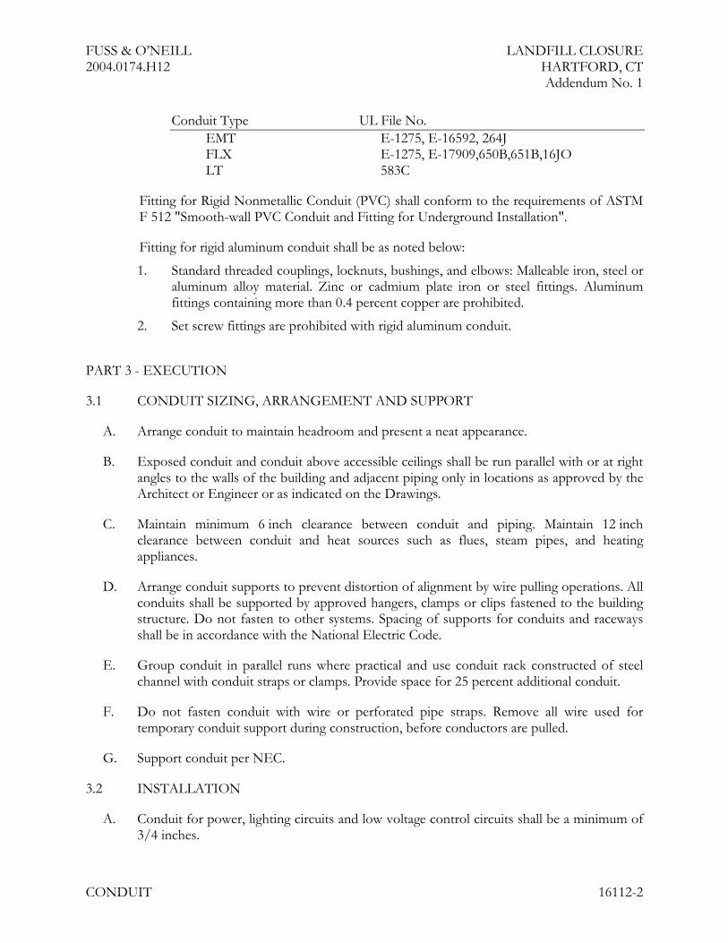
Conduit Type UL File No.EMT E-1275, E-16592, 264JFLX E-1275, E-17909,650B,651B,16JOLT 583C
Fitting for Rigid Nonmetallic Conduit (PVC) shall conform to the requirements of ASTMF 512 "Smooth-wall PVC Conduit and Fitting for Underground Installation".
Fitting for rigid aluminum conduit shall be as noted below:
1. Standard threaded couplings, locknuts, bushings, and elbows: Malleable iron, steel oraluminum alloy material. Zinc or cadmium plate iron or steel fittings. Aluminumfittings containing more than 0.4 percent copper are prohibited.
2. Set screw fittings are prohibited with rigid aluminum conduit.
PART 3 - EXECUTION
3.1 CONDUIT SIZING, ARRANGEMENT AND SUPPORT
A. Arrange conduit to maintain headroom and present a neat appearance.
B. Exposed conduit and conduit above accessible ceilings shall be run parallel with or at rightangles to the walls of the building and adjacent piping only in locations as approved by theArchitect or Engineer or as indicated on the Drawings.
C. Maintain minimum 6 inch clearance between conduit and piping. Maintain 12 inchclearance between conduit and heat sources such as flues, steam pipes, and heatingappliances.
D. Arrange conduit supports to prevent distortion of alignment by wire pulling operations. Allconduits shall be supported by approved hangers, clamps or clips fastened to the buildingstructure. Do not fasten to other systems. Spacing of supports for conduits and racewaysshall be in accordance with the National Electric Code.
E. Group conduit in parallel runs where practical and use conduit rack constructed of steelchannel with conduit straps or clamps. Provide space for 25 percent additional conduit.
F. Do not fasten conduit with wire or perforated pipe straps. Remove all wire used fortemporary conduit support during construction, before conductors are pulled.
G. Support conduit per NEC.
3.2 INSTALLATION
A. Conduit for power, lighting circuits and low voltage control circuits shall be a minimum of3/4 inches.

FUSS & O’NEILL LANDFILL CLOSURE2004.0174.H12 HARTFORD, CT
Addendum No. 1
CONDUIT 16112-3
B. All metal conduit, enclosures and raceways for conductors shall be mechanically joinedtogether to form a continuous electrical continuity and bond. Provide grounding bushingson all conduits 1-1/4 inches and larger.
C. All conduits shall be concealed in finished areas unless otherwise noted and so installed soas not to damage structural members.
D. Conduits shall be in full lengths wherever possible and all ends shall be cut square, reamedand burred.
E. Bring conduit to the shoulder of fittings and couplings and fasten securely.
F. Use conduit hubs or sealing locknuts for fastening conduit to cast boxes, and for fasteningconduit to sheet metal boxes in damp or wet locations.
G. Install no more than the equivalent of four 90 degree bends in between boxes.
H. Use conduit bodies to make sharp changes in direction.
I. Use hydraulic one-shot conduit bender or factory elbows for bends in conduit larger than2 inches in size.
J. Electric metallic tubing shall be assembled with approved concrete tight die cast fittingswith 2 set screws per pipe end, standard radius bends. When tubing is exposed, "L" fittingsmay be used.
K. Follow connector manufacturers' instructions and NEC requirements when connectingFLX, and LT conduit to junction and outlet boxes. A separate internal groundingconductor shall be installed.
L. The use of wooden plugs inserted in concrete or masonry units as base for fasteningsconduits, tubing, boxes, cabinets, or other equipment shall be prohibited.
M. The installation of conduit or tubing which has been crushed or deformed shall beprohibited.
N. All conduits shall be plugged with approved discs during construction and be dry and cleanbefore pulling wires.
O. Install conduit to prevent low spots which might accumulate water during or afterinstallation. Where unavoidable, provide junction box with drain fitting at conduit lowpoint.
P. Where conduit penetrates fire-rated walls and floors, provide pipe sleeve two sizes largerthan conduit; pack void around conduit with fire rated flexible sealer and fill ends of sleevewith fire-resistive compound.

FUSS & O’NEILL LANDFILL CLOSURE2004.0174.H12 HARTFORD, CT
Addendum No. 1
CONDUIT 16112-4
3.3 LABELING
A. Labeling shall be as specified in Section 16195.
END OF SECTION
FUSS & O’NEILL LANDFILL CLOSURE2004.0174.H12 HARTFORD, CT
Addendum No. 1
WIRE AND CABLE 16120-1
SECTION 16120 - WIRE AND CABLE
PART 1 - GENERAL
1.1 WORK INCLUDED
A. Provide all material and labor for the complete installation of wire and cable required forelectrical work specified in other Sections of this Specification or as indicated on theDrawings.
1.2 PROJECT CONDITIONS
A. Verify that field measurements are as shown on Drawings.
B. Conductor sizes are based on copper.
C. Wire and cable routing shown on Drawings is approximate unless dimensioned. Route wireand cable as required meeting Project Conditions.
D. Where wire and cable routing is not shown, and destination only is indicated, determineexact routing and lengths required.
PART 2 - PRODUCTS
2.1 MATERIALS
A. All wire sizes indicated on Drawings and this Specification are based on copperconductors. All conductors provided shall be copper.
B. Provide copper conductors installed in conduit for power and lighting. (NEC TypeTHWN) Conductors shall be 98% conductivity solid or class B concentric strand copperwith 600 volt thermoplastic insulation manufactured in accordance with UL 83.
C. Minimum size of conductor shall be No. 12. Conductors of size greater than No. 8 shall bestranded.
D. Copper conductor installed in conduit for low voltage control. (NEC Class 2 cable)Minimum size of conductor shall be No. 16.
E. Conductor shall be marked in accordance with the requirements of the NEC Article310-11. Conductors shall be identified in accordance with the requirements of the NECArticle 310-12 and as indicated below:
1. Circuit with:
a. two conductors White, Black
FUSS & O’NEILL LANDFILL CLOSURE2004.0174.H12 HARTFORD, CT
Addendum No. 1
WIRE AND CABLE 16120-2
b. three conductors White, Black, Red
c. four conductors White, Black, Red, Blue
d. five conductors White, Black, Red, Blue, Yellow
PART 3 - EXECUTION
3.1 EXAMINATION
A. Verify that mechanical work likely to damage wire has been completed.
3.2 PREPARATION
A. Completely and thoroughly swab raceway before installing wire.
3.3 INSTALLATION
A. Install all wire in accordance with Section 16050, manufacturer’s instructions and the NECrequirements.
B. All connections and pigtail splices for wires #14-#10 shall be made with insulated type"Y", "R", or "B" spring connectors or compression splices. Conductor sizes #8 and largershall be made with compression connectors.
C. Use split bolt connectors for copper conductor splices and taps, 6 AWG and larger. Tapeuninsulated conductors and connector with electrical tape to 150 percent of insulationrating of conductor.
D. Make splices, taps, and terminations to carry full ampacity of conductors with noperceptible temperature rise.
E. Use conductor not smaller than 12 AWG for power and lighting circuits.
F. Use solid conductors for feeders and branch circuits 10 AWG and smaller.
G. Use stranded conductors not smaller than 14 AWG for control circuits.
H. There shall be no splices in any conductors except where circuits are branched and locatedin accessible junction or outlet box.
I. Unless otherwise noted, each conduit raceway shall contain only those conductorsconstituting a single feeder circuit.
J. Branch circuit home runs shall not share a common neutral. Neutral conductors shall be ofsame size as phase conductors unless specifically noted otherwise.
K. Pull all conductors into raceway at same time.

FUSS & O’NEILL LANDFILL CLOSURE2004.0174.H12 HARTFORD, CT
Addendum No. 1
WIRE AND CABLE 16120-3
L. Protect cable from damage.
M. Clean conductor surfaces before installing lugs and connectors.
N. Neatly train and lace wiring inside boxes, equipment and panelboards.
O. Run conductors of same circuit in same conduit. Run conductors of different voltagesystems in separate conduits.
P. All feeder and branch circuits shall have a full size separate grounding conductor installedin the conduit.
3.4 INTERFACE WITH OTHER PRODUCTS
A. Identify each conductor with its circuit number or other designation indicated onDrawings.
3.5 FIELD QUALITY CONTROL
A. Do not pull conductors into conduit until raceway system is complete and cabinets andoutlet boxes are free of foreign matter and moisture.
B. Only UL approved wire pulling lubricant shall be used.
C. Insulation integrity shall be tested before energizing any circuits.
D. Verify continuity of each branch circuit conductor.
E. Inspect wire for physical damage and proper connection.
F. Perform field inspection and testing under provisions of Division 1.
END OF SECTION
FUSS & O’NEILL LANDFILL CLOSURE2004.0174.H12 HARTFORD, CT
Addendum No. 1
ELECTRICAL IDENTIFICATION 16195-1
SECTION 16195 - ELECTRICAL IDENTIFICATION
PART 1 - GENERAL
1.1 WORK INCLUDED
A. Nameplates and labels.
B. Wire and cable markers.
C. Conduit markers.
D. As indicated in other sections or on the Drawings.
1.2 REFERENCES
A. ANSI/NFPA 70 - National Electrical Code.
1.3 SUBMITTALS
A. Submit under provisions of Division 1.
B. Product Data: Provide catalog data for nameplates, labels, and markers.
C. Manufacturer's Instructions: Indicate application conditions and limitations of usestipulated by Product testing agency specified under regulatory requirements. Includeinstructions for storage, handling, protection, examination, preparation and installation ofProduct.
1.4 REGULATORY REQUIREMENTS
A. Furnish products listed and classified by Underwriters Laboratories, Inc.
B. Installation shall conform to all requirements of NFPA 70, National Electric Code.
PART 2 - PRODUCTS
2.1 NAMEPLATES AND LABELS
A. Nameplates: Engraved three-layer laminated plastic, white letters on black background notless than 3/4" x 2 1/2" in size.
B. Locations:
1. Each electrical distribution and control equipment enclosure including but notlimited to the following:

FUSS & O’NEILL LANDFILL CLOSURE2004.0174.H12 HARTFORD, CT
Addendum No. 1
ELECTRICAL IDENTIFICATION 16195-2
a. All switchgear
b. Panelboards
c. Motor switches & contactors, other motor controls
2. J-boxes larger than 12" x 12".
3. Pull boxes larger than 12" x 12".
C. Letter Size:
1. Use 1/2 inch letters for identifying individual equipment and loads.
D. Labels: Embossed adhesive tape, with 3/16 inch white letters on black background.Use for identification of individual wall switches and receptacles. Indicate circuit numbers.
2.2 WIRE MARKERS
A. Description: Tape or tubing type wire markers.
B. Locations: Each conductor at panelboard gutters, pull boxes, outlet and junction boxes,and each load connection.
C. Legend:
1. Power and Lighting Circuits: Branch circuit or feeder number indicated ondrawings.
2.3 UNDERGROUND WARNING TAPE
A. Description: 6 inch wide plastic tape, magnetic detectable type, colored red with suitablewarning legend describing buried electrical lines; Style 57360 as manufactured by SetonName Plate Co.
PART 3 - EXECUTION
3.1 PREPARATION
A. Submit list of proposed wording to Engineer for approval.
B. Degrease and clean surfaces to receive nameplates and labels.
3.2 APPLICATION
A. Install nameplate and label parallel to equipment lines.
B. Secure nameplate to equipment front using screws or rivets.
FUSS & O’NEILL LANDFILL CLOSURE2004.0174.H12 HARTFORD, CT
Addendum No. 1
ELECTRICAL IDENTIFICATION 16195-3
C. Secure nameplate to inside surface of door on panelboard that is recessed in finishedlocations.
D. Identify underground conduits using underground warning tape. Install one tape per trenchat depth indicated on Drawings.
END OF SECTION
FUSS & O’NEILL LANDFILL CLOSURE2004.0174.H12 HARTFORD, CT
Addendum No. 1
VARIABLE FREQUENCY CONTROLLERS 16269 - 1
SECTION 16269 - VARIABLE FREQUENCY CONTROLLERS
PART 1 - GENERAL
1.1 RELATED DOCUMENTS
A. Drawings and general provisions of the Contract, including General and SupplementaryConditions and Division 1 Specification Sections, apply to this Section.
1.2 SUMMARY
A. This Section includes solid-state, PWM, VFCs for speed control of three-phase, squirrel-cage induction motors.
1.3 DEFINITIONS
A. BMS: Building management system.
B. IGBT: Integrated gate bipolar transistor.
C. LAN: Local area network.
D. PID: Control action, proportional plus integral plus derivative.
E. PWM: Pulse-width modulated.
F. VFC: Variable frequency controller.
1.4 SUBMITTALS
A. Product Data: For each type of VFC. Include dimensions, mounting arrangements,location for conduit entries, shipping and operating weights, and manufacturer's technicaldata on features, performance, electrical ratings, characteristics, and finishes.
B. Shop Drawings: For each VFC.
1. Include dimensioned plans, elevations, sections, and details, including requiredclearances and service space around equipment. Show tabulations of installeddevices, equipment features, and ratings. Include the following:
a. Each installed unit's type and details.
b. Nameplate legends.
c. Short-circuit current rating of integrated unit.
d. Listed and labeled for series rating of overcurrent protective devices incombination controllers by an NRTL acceptable to authorities havingjurisdiction.

FUSS & O’NEILL LANDFILL CLOSURE2004.0174.H12 HARTFORD, CT
Addendum No. 1
VARIABLE FREQUENCY CONTROLLERS 16269 - 2
e. Features, characteristics, ratings, and factory settings of each motor-controlcenter unit.
2. Wiring Diagrams: Power, signal, and control wiring for VFCs. Provide schematicwiring diagram for each type of VFC.
C. Coordination Drawings: Floor plans, drawn to scale, showing dimensioned layout,required working clearances, and required area above and around VFCs where pipe andducts are prohibited. Show VFC layout and relationships between electrical componentsand adjacent structural and mechanical elements. Show support locations, type of support,and weight on each support. Indicate field measurements.
D. Manufacturer Seismic Qualification Certification: Submit certification that VFCs,accessories, and components will withstand seismic forces defined in Division 16 Section"Electrical Supports and Seismic Restraints." Include the following:
1. Basis for Certification: Indicate whether withstand certification is based on actualtest of assembled components or on calculation.
a. The term "withstand" means "the unit will remain in place without separationof any parts from the device when subjected to the seismic forces specified."
b. The term "withstand" means "the unit will remain in place without separationof any parts from the device when subjected to the seismic forces specifiedand the unit will be fully operational after the seismic event."
2. Dimensioned Outline Drawings of Equipment Unit: Identify center of gravity andlocate and describe mounting and anchorage provisions.
3. Detailed description of equipment anchorage devices on which the certification isbased and their installation requirements.
E. Field quality-control test reports.
F. Operation and Maintenance Data: For VFCs, all installed devices, and components toinclude in emergency, operation, and maintenance manuals. In addition to items specifiedin Division 1 Section "Operation and Maintenance Data," include the following:
1. Routine maintenance requirements for VFCs and all installed components.
2. Manufacturer's written instructions for testing and adjusting overcurrent protectivedevices.
G. As-Built Wiring Diagrams (upon completion of project): Power, signal, and control wiringfor VFCs. For each type of VFC, provide schematic wiring diagram, electrical enclosurelayout, and interconnection diagram.
H. Provide VFC programmed parameters / configuration in hand-written format.
I. Load-Current and Overload-Relay Heater List: Compile and arrange to demonstrate thatselection of heaters suits actual motor nameplate full-load currents.

FUSS & O’NEILL LANDFILL CLOSURE2004.0174.H12 HARTFORD, CT
Addendum No. 1
VARIABLE FREQUENCY CONTROLLERS 16269 - 3
J. Load-Current and List of Settings of Adjustable Overload Relays: Compile arrange todemonstrate that dip switch settings for motor running overload protection suit actualmotor to be protected.
1.5 QUALITY ASSURANCE
A. Manufacturer Qualifications: A qualified manufacturer. Maintain, within 100 miles ofProject site, a service center capable of providing training, parts, and emergencymaintenance and repairs.
B. Source Limitations: Obtain VFCs of a single type through one source from a singlemanufacturer.
C. Electrical Components, Devices, and Accessories: Listed and labeled as defined inNFPA 70, Article 100, by a testing agency acceptable to authorities having jurisdiction, andmarked for intended use.
D. Compliance with:
1. NFPA 70.
2. ANSI/NEMA ICS 3 – Industrial Systems
3. NEMA ICS 3.1: Safety Standards for Construction and Guide for Selection,Installation and Operation of Adjustable Speed Drive Systems.
E. Product Selection for Restricted Space: Drawings indicate maximum dimensions forVFCs, minimum clearances between VFCs, and adjacent surfaces and other items. Complywith indicated maximum dimensions and clearances.
F. The Drive manufacturing facility will be ISO 9001 and 14001 certified.
G. The VFD will be UL listed, or Canadian UL listed, and complies with EMC Directive89/336 EEC, Low Voltage Directive 73/23 EEC and Machinery Directive 98/37 EC inaccordance with the European Union’s CE directive.
1.6 DELIVERY, STORAGE, AND HANDLING
A. Deliver VFCs in shipping splits of lengths that can be moved past obstructions in deliverypath as indicated.
B. Store VFCs indoors in clean, dry space with uniform temperature to prevent condensation.Protect VFCs from exposure to dirt, fumes, water, corrosive substances, and physicaldamage.
C. If stored in areas subject to weather, cover VFCs to protect them from weather, dirt, dust,corrosive substances, and physical damage. Remove loose packing and flammablematerials from inside controllers; install electric heating of sufficient wattage to preventcondensation.

FUSS & O’NEILL LANDFILL CLOSURE2004.0174.H12 HARTFORD, CT
Addendum No. 1
VARIABLE FREQUENCY CONTROLLERS 16269 - 4
1.7 PROJECT CONDITIONS
A. Environmental Limitations: Rate equipment for continuous operation, capable of drivingfull load without derating, under the following outdoor conditions, unless otherwiseindicated:
1. Ambient Temperature: -10 to 110 deg F.
2. Humidity: Less than 90 percent (noncondensing).
3. Altitude: Not exceeding 3300 feet.
B. Interruption of Existing Electrical Service: Do not interrupt electrical service to facilitiesoccupied by Owner or others unless permitted under the following conditions and thenonly after arranging to provide temporary electrical service according to requirementsindicated:
1. Notify Owner no fewer than two (2) days in advance of proposed interruption ofelectrical service.
2. Indicate method of providing temporary electrical service.
3. Do not proceed with interruption of electrical service without Owner’s writtenpermission.
C. Product Selection for Restricted Space: Drawings indicate maximum dimensions forVFCs, including clearances between VFCs, and adjacent surfaces and other items. Complywith indicated maximum dimensions.
1.8 COORDINATION
A. Coordinate layout and installation of VFCs with other construction including conduit,piping, equipment, and adjacent surfaces. Maintain required workspace clearances andrequired clearances for equipment access doors and panels.
B. Coordinate size and location of concrete bases. Cast anchor-bolt inserts into bases.Concrete, reinforcement, and formwork requirements are specified in Division 3 Section"Cast-in-Place Concrete."
C. Coordinate features of VFCs, installed units, and accessory devices with pilot devices andcontrol circuits to which they connect.
D. Coordinate features, accessories, and functions of each VFC and each installed unit withratings and characteristics of supply circuit, motor, required control sequence, and dutycycle of motor and load.
FUSS & O’NEILL LANDFILL CLOSURE2004.0174.H12 HARTFORD, CT
Addendum No. 1
VARIABLE FREQUENCY CONTROLLERS 16269 - 5
1.9 EXTRA MATERIALS
A. Furnish extra materials described below that match products installed and that arepackaged with protective covering for storage and identified with labels describingcontents.
1. Spare Fuses: Furnish one spare for every five (5) installed, but no fewer than one setof three (3) of each type and rating.
2. Indicating Lights: Two (2) of each type installed.
3. Control Relays: Two (2) of each type installed.
PART 2 - PRODUCTS
2.1 MANUFACTURERS
A. Available Manufacturers: Subject to compliance with requirements, manufacturers offeringproducts that may be incorporated into the Work include, but are not limited to, thefollowing:
B. Manufacturers: Subject to compliance with requirements, provide products by one of thefollowing:
1. AC Tech Sub-Micro Drive, SM4100.
2. ABB Power Distribution, Inc.; ABB Control, Inc. Subsidiary.
3. Danfoss Inc.; Danfoss Electronic Drives Div.
4. Eaton Corporation; Cutler-Hammer Products.
5. General Electric Company; GE Industrial Systems.
6. Rockwell Automation; Allen-Bradley Co.; Industrial Control Group.
7. Siemens Energy and Automation; Industrial Products Division.
8. Square D.
9. Toshiba International Corporation.
2.2 VARIABLE FREQUENCY CONTROLLERS
A. Description: NEMA ICS 2, IGBT, PWM, VFC; listed and labeled as a complete unit andarranged to provide variable speed of an NEMA MG 1, Design B, 3-phase inductionmotor by adjusting output voltage and frequency.
1. Provide unit suitable for operation of standard-efficiency motor as defined byNEMA MG 1.
B. Provide VFC for each pump.
FUSS & O’NEILL LANDFILL CLOSURE2004.0174.H12 HARTFORD, CT
Addendum No. 1
VARIABLE FREQUENCY CONTROLLERS 16269 - 6
C. Design and Rating: Match load type such as fans, blowers, and pumps; and type ofconnection used between motor and load such as direct or through a power-transmissionconnection.
D. Output Rating: 3-phase; 6 to 60 Hz, with voltage proportional to frequency throughoutvoltage range.
E. Unit Operating Requirements:
1. Input ac voltage tolerance of 380 to 500 V, plus or minus 10 percent.
2. Input frequency tolerance of 50/60 Hz, plus or minus 6 percent.
3. Minimum Efficiency: 96 percent at 60 Hz, full load.
4. Minimum Displacement Primary-Side Power Factor: 96 percent.
5. Overload Capability: 1.1 times the base load current for 60 seconds; 2.0 times thebase load current for 3 seconds.
6. Starting Torque: 100 percent of rated torque or as indicated.
7. Speed Regulation: Plus or minus 1 percent.
F. Isolated control interface to allow controller to follow control signal over an 11:1 speedrange.
1. Electrical Signal: 4 to 20 mA at 24 V.
2. Electrical Signal: 0 to 10 volts.
G. Internal Adjustability Capabilities:
1. Minimum Speed: 5 to 25 percent of maximum rpm.
2. Maximum Speed: 80 to 100 percent of maximum rpm.
3. Acceleration: 2 to a minimum of 22 seconds.
4. Deceleration: 2 to a minimum of 22 seconds.
5. Current Limit: 50 to a minimum of 110 percent of maximum rating.
H. Self-Protection and Reliability Features:
1. Input transient protection by means of surge suppressors.
2. Under- and overvoltage trips; inverter overtemperature, overload, and overcurrenttrips.
3. Motor Overload Relay: Adjustable and capable of NEMA ICS 2, Class 10, 20, 30performance.
4. Notch filter to prevent operation of the controller-motor-load combination at anatural frequency of the combination.
5. Instantaneous line-to-line and line-to-ground overcurrent trips.

FUSS & O’NEILL LANDFILL CLOSURE2004.0174.H12 HARTFORD, CT
Addendum No. 1
VARIABLE FREQUENCY CONTROLLERS 16269 - 7
6. Loss-of-phase protection.
7. Reverse-phase protection.
8. Short-circuit protection.
9. Motor over-temperature fault.
I. Multiple-Motor Capability: Controller suitable for service to multiple motors and having aseparate overload relay and protection for each controlled motor. Overload relay shall shutoff controller and motors served by it when overload relay is tripped.
J. Automatic Reset/Restart: Capable of Attempting three restarts after controller fault or onreturn of power after an interruption and before shutting down for manual reset or faultcorrection. Bidirectional autospeed search shall be capable of starting into rotating loadsspinning in either direction and returning motor to set speed in proper direction, withoutdamage to controller, motor, or load.
K. Power-Interruption Protection: To prevent motor from re-energizing after a powerinterruption until motor has stopped.
L. Torque Boost: Automatically varies starting and continuous torque to at least 1.5 times theminimum torque to ensure high-starting torque and increased torque at slow speeds.
M. Motor Temperature Compensation at Slow Speeds: Adjustable current fall-back based onoutput frequency for temperature protection of self-cooled, fan-ventilated motors at slowspeeds.
N. VFD Output Filtering: Provide dv/dt load filters in lines of excess of 150 feet to reduceline reflectance.
O. Parameter Indication: Integral LCD display to indicate the following controllerparameters:
1. Output frequency (Hz).
2. Motor speed (rpm).
3. Motor status (running, stop, fault).
4. Motor current (amperes).
5. Motor torque (percent).
6. Fault or alarming status (code).
7. PID feedback signal (percent).
8. DC-link voltage (VDC).
9. Set-point frequency (Hz).
10. Motor output voltage (V).

FUSS & O’NEILL LANDFILL CLOSURE2004.0174.H12 HARTFORD, CT
Addendum No. 1
VARIABLE FREQUENCY CONTROLLERS 16269 - 8
P. Control Signal Interface:
1. Electric Input Signal Interface: A minimum of 2 analog inputs (0 to 10 V or 0/4-20mA) and 6 programmable digital inputs.
2. Remote Signal Inputs: Capability to accept any of the following speed-setting inputsignals from the BMS or other control systems:
a. 0 to 10-V dc.
b. 0-20 or 4-20 mA.
c. Potentiometer using up/down digital inputs.
d. Fixed frequencies using digital inputs.
e. Keypad display for local hand operation.
3. Remote Indication Interface: A minimum of 1 dry circuit relay outputs (120-V ac,1 A) for remote indication of any the following:
a. Motor running.
b. Fault and warning indication (overtemperature or overcurrent).
c. PID high- or low-speed limits reached.
Q. Integral Disconnecting Means: NEMA AB 1, instantaneous-trip circuit breaker withlockable handle.
R. Remote Indicating Circuit Terminals: Mode selection and start/stop operation, controllerstatus, and controller fault.
2.3 ENCLOSURES
A. Provide NEMA 3R Steel Enclosure:
1. Provide integral fan heating unit with thermostat.
2. Provide cooling fan with thermostat.
3. Provide locking mechanism.
4. Provide schematic pocket.
5. Provide drip shield.
PART 3 - EXECUTION
3.1 EXAMINATION
A. Examine areas, surfaces, and substrates to receive VFCs for compliance with requirements,installation tolerances, and other conditions affecting performance.

FUSS & O’NEILL LANDFILL CLOSURE2004.0174.H12 HARTFORD, CT
Addendum No. 1
VARIABLE FREQUENCY CONTROLLERS 16269 - 9
B. The General Contractor shall install VFDs in accordance with Contract Drawings as aninitial guide. The General Contractor shall install VFDs in accordance with VFDmanufacturers recommended separation distances for ventilation purposes.
C. Examine roughing-in for conduit systems to verify actual locations of conduit connectionsbefore VFC installation.
D. Proceed with installation only after unsatisfactory conditions have been corrected.
3.2 APPLICATIONS
A. Select features of each VFC to coordinate with ratings and characteristics of supply circuitand motor; required control sequence; and duty cycle of motor, controller, and load.
B. Select horsepower rating of controllers to suit motor controlled: Provide 10 HP VariableTorque VFC.
3.3 INSTALLATION
A. Anchor each VFC enclosure assembly to stainless-steel uni-strut and sized according tomanufacturer's written instructions. Attach by bolting using stainless-steel mountinghardware. Install level and flush with mounting surface.
B. Comply with mounting and anchoring requirements specified in Division 16 Section"Electrical Supports and Seismic Restraints."
C. Install on existing uni-strut stanchion as indicated on Electrical Details.
3.4 IDENTIFICATION
A. Identify VFCs, components, and control wiring according to Division 16 Section"Electrical Identification."
B. Operating Instructions: Frame printed operating instructions for VFCs, including controlsequences and emergency procedures. Provide and place both in O&M and enclosureprint pocket.
3.5 CONTROL WIRING INSTALLATION
A. Install wiring between VFCs and remote devices according to Division 16 Section"Conductors and Cables."
B. Bundle, train, and support wiring in enclosures.
C. Modify existing duplex pump control system and provide dry “run” contacts to VariableFrequency Controller’s Run Circuit on Drive’s Control Terminal Block for each pump.

FUSS & O’NEILL LANDFILL CLOSURE2004.0174.H12 HARTFORD, CT
Addendum No. 1
VARIABLE FREQUENCY CONTROLLERS 16269 - 10
D. Provide programming of “pre-selected” speed with associated wiring on Drive’s ControlTerminal Block for each pump. Pre-selected speed shall be as appropriate for pump’s newduty point.
E. Modify existing duplex pump control system and provide a “VFD Fault” pilot light wiredto the VFC’s programmable output contact on the Drive’s Control Terminal Block foreach pump.
3.6 CONNECTIONS
A. Conduit installation requirements are specified in other Division 16 Sections. Drawingsindicate general arrangement of conduit, fittings, and specialties.
B. Ground equipment according to Division 16 "Grounding and Bonding."
3.7 FIELD QUALITY CONTROL
A. The Contractor Shall provide the acceptance tests as follows:
1. Test insulation resistance for each enclosed controller element, bus, component,connecting supply, feeder, and control circuit.
2. Test continuity of each circuit.
3. Report results in writing.
B. Perform the following field tests and inspections and prepare test reports:
1. Perform each electrical test and visual and mechanical inspection, except optionaltests, stated in NETA ATS. Certify compliance with test parameters.
2. Correct malfunctioning units on-site, where possible, and retest to demonstratecompliance; otherwise, replace with new units and retest.
3.8 PROGRAMMING AND ADJUSTING
A. Set field-adjustable switches and circuit-breaker trip ranges.
B. Program VFC to operate at pump’s new duty point of 30ft of head, 200 gpm, 8horsepower, at approximately 1090 RPM.
3.9 DEMONSTRATION
A. Train Owner's maintenance personnel to adjust, operate, and maintain variable frequencycontrollers. Refer to Division 1 Section "Demonstration and Training."
1. Provide no less than two (2) hours of training, video taped and submitted to Owneralong with O&M.

FUSS & O’NEILL LANDFILL CLOSURE2004.0174.H12 HARTFORD, CT
Addendum No. 1
VARIABLE FREQUENCY CONTROLLERS 16269 - 11
2. Provide operator training sign-off sheet with name, title, entity, date, time, signaturecolumns to be signed by operators and maintenance staff who receive training.Furnish completed copies to Owner and Engineer.
END OF SECTION
FUSS & O’NEILL LANDFILL CLOSURE2004.0174.H12 HARTFORD, CT
Addendum No. 1
OVERHEAD ELECTRICAL DISTRIBUTION 16315 - 1
SECTION 16315 - OVERHEAD ELECTRICAL DISTRIBUTION
PART 1 - GENERAL
1.1 RELATED DOCUMENTS
A. Drawings and general provisions of the Contract, including General and SupplementaryConditions and Division 1 Specification Sections, apply to this Section.
1.2 SUMMARY
A. This Section includes secondary-voltage, overhead electrical power distribution and thefollowing:
1. Conductors, connectors, and splices.
2. Wood poles and crossarms.
3. Hardware and accessories.
4. Surge arresters.
1.3 DEFINITIONS
A. ACSR: Aluminum conductor, steel reinforced.
B. BIL: Basic impulse level, stated in kilovolts.
C. HDPE: High-density polyethylene.
D. RUS: Department of Agriculture, Rural Utilities Service.
E. Sag: The distance measured vertically from a conductor to the straight line joining its twopoints of support, measured at the midpoint of the span, unless otherwise indicated.
1. Final Sag: The sag of a conductor under specified conditions of loading andtemperature applied after it has been subjected, for an appreciable period, to theloading prescribed for the loading district in which it is situated, or equivalentloading, and the loading removed. Final sag includes the effect of inelasticdeformation (creep).
2. Initial Unloaded Sag: The sag of a conductor before the application of an externalload.
F. Secondary: Conductors and components for circuits operating at the utilization voltage of600 V or less.
G. Service: Set of insulated conductors extending from a pole to the metering point or serviceentrance connection at the location of utilization of electricity.
FUSS & O’NEILL LANDFILL CLOSURE2004.0174.H12 HARTFORD, CT
Addendum No. 1
OVERHEAD ELECTRICAL DISTRIBUTION 16315 - 2
1.4 SUBMITTALS
A. Product Data: For the following:
1. Conductors.
2. Poles.
3. Crossarms.
4. Insulators.
5. Surge arresters.
6. Guy assemblies.
B. Material Inspection Reports: From a qualified independent inspection agency indicatingcompliance of wood poles and crossarms with requirements indicated. RUS quality mark"WQC" on each item is acceptable in place of inspection as evidence of compliance.
C. Listing Documentation: Indicate products comply with RUS listing requirements specifiedin "Quality Assurance" Article.
D. Field quality-control test reports.
E. Source Quality-Control Test Reports: Factory inspection reports of wood poles.
1.5 QUALITY ASSURANCE
A. Inspection Agency Qualifications for Pole and Crossarm Inspection: An independentagency, acceptable to authorities having jurisdiction, qualified to conduct inspectionsindicated.
B. Treatment Technician Qualifications for Field Treatment of Wood Poles and Crossarms:Certified by authorities having jurisdiction over environmental protection at the location ofProject for field application of chemicals required.
C. Electrical Components Normally Covered by Listing and Labeling Services: Listed andlabeled as defined in NFPA 70, Article 100, by a testing agency acceptable to authoritieshaving jurisdiction, and marked for intended use.
D. Overhead-Line Components, Devices, and Accessories: Currently listed in RUSInformational Publication 202-1 without restriction for the intended application.
E. Comply with IEEE C2, except where stricter requirements are indicated or where localrequirements that are stricter apply.
F. Strength of Line and Line Components Selected by Contractor: Provide grades ofconstruction and strength required by IEEE C2 for conditions encountered at Project sitefor medium line loading, unless otherwise indicated.

FUSS & O’NEILL LANDFILL CLOSURE2004.0174.H12 HARTFORD, CT
Addendum No. 1
OVERHEAD ELECTRICAL DISTRIBUTION 16315 - 3
1.6 DELIVERY, STORAGE, AND HANDLING
A. Wood Pole Storage and Handling: Comply with ANSI O5.1. Do not use pointed handlingtools capable of producing indentations greater than 1 inch.
1.7 PROJECT CONDITIONS
A. Existing Utilities: Do not interrupt utilities serving facilities occupied by Owner or othersunless permitted under the following conditions and then only after arranging to providetemporary utility services according to requirements indicated:
1. Notify Owner not less than two days in advance of proposed utility interruptions.
2. Do not proceed with utility interruptions without Owner’s written permission.
PART 2 - PRODUCTS
2.1 MANUFACTURERS
A. In other Part 2 articles where titles below introduce lists, the following requirements applyto product selection:
1. Available Manufacturers: Subject to compliance with requirements, manufacturersoffering products that may be incorporated into the Work include, but are notlimited to, manufacturers specified.
2. Manufacturers: Subject to compliance with requirements, provide products by oneof the manufacturers specified.
2.2 CONDUCTORS, CONNECTORS, AND SPLICES
A. Acceptable Manufacturers - Conductors:
1. AFC Cable Systems.
2. Alcan Cable Co.
3. BICC Cables Company.
4. Brugg Telecom Inc.
5. Florida Wire & Cable, Inc.
6. General Wire & Cable Co.
7. Hendrix Wire and Cable Inc.
8. Kerite Company (The); Innovation Systems Inc.
9. King Wire Inc.
10. Nokia Cables USA Inc.
11. Northern Lights Cable, Inc.

FUSS & O’NEILL LANDFILL CLOSURE2004.0174.H12 HARTFORD, CT
Addendum No. 1
OVERHEAD ELECTRICAL DISTRIBUTION 16315 - 4
12. Okonite Company (The).
13. Rome Cable Corp.
14. Southwire Company.
15. Approved Equal
B. Acceptable Manufacturers - Connectors and Splices:
1. AB Chance Co.; Hubbell, Inc.
2. Connector Manufacturing Co.
3. Cooper Power Systems.
4. Hubbell, Inc.; Anderson Electrical Products, Inc.
5. Hubbell, Inc.; Fargo Manufacturing Company.
6. Approved Equal
C. Secondary-Voltage Line Conductors: Covered hard-drawn copper, complying withICEA S-70-547, with HDPE covering
D. Connectors, Splices, and Conductor Securing and Protecting Components: Items includewire clamps, ties, conductor armor, fittings, connectors, and terminals. Listed for thespecific applications and conductor types and combinations of materials used.Descriptions as follows for various applications:
1. Copper to Copper: Copper alloy, complying with UL 486A.
2. Aluminum Composition to Aluminum Composition: Aluminum alloy, complyingwith UL 486B.
3. Copper to Aluminum Composition: Type suitable for this purpose, complying withUL 486B.
4. Connectors and Splices for Secondary Conductors: Listed and labeled for theconditions and materials involved in each application.
5. Splices under Tension: Compression type with strength exceeding the conductorsspliced.
6. Splices and Terminations for Covered Conductors: As recommended by conductormanufacturer for conductor and covering combination and for specific materials andphysical arrangement of each splice.
2.3 WOOD POLES
A. Approved Manufacturers:
1. Bell Lumber & Pole Co.
2. B. J. Carney & Co., Ltd.

FUSS & O’NEILL LANDFILL CLOSURE2004.0174.H12 HARTFORD, CT
Addendum No. 1
OVERHEAD ELECTRICAL DISTRIBUTION 16315 - 5
3. Brown Wood Preserving Co.
4. GRA Services International, Inc.
5. J. H. Baxter & Co.
6. Koppers Industries, Inc.
7. McFarland Cascade.
8. Okonite Company (The).
9. Taylor Lumber & Treating.
10. Western Red Cedar Lumber Association.
11. Approved Equal
B. Description: Wood poles comply with ANSI O5.1 and treated according to AWPA C4with oil-borne preservatives and petroleum complying with AWPA P8 and AWPA P9.
C. Pole Marking Location: 10 feet from the pole butt for poles 50 feet long or less.
D. Factory Operations: Machine trim poles by turning smooth, full length. Roof, gain, andbore poles before pressure treatment.
2.4 CROSSARMS
A. Description: Solid-wood distribution type, complying with RUS REA Bulletin 1728H-701for specified construction grade and IEEE C2 for required climbing space and wireclearances.
B. Braces: Galvanized, flat, ferrous-metal units; 1/4 inch thick by 1-/4 inches wide,minimum, with length to suit crossarm dimensions.
2.5 HARDWARE AND ACCESSORIES
A. Description: Ferrous-metal items include, but are not limited to, bolts, nuts, washers,crossarm gains and braces, insulator pins, anchor rods, anchors, eyebolts, staples, andtransformer brackets.
1. Comply with ANSI C135.1, ANSI C135.2, ANSI C135.4, ANSI C135.14,ANSI C135.22, ANSI C135.33, and RUS Informational Publication 202-1listings with the exception that base material shall be malleable iron or ductile iron,and finish shall be hot-dip galvanized.
B. Guy Strand Assemblies: Cable and attachments. Include strain insulators where indicatedand if required by IEEE C2. Assemblies shall have uniform minimum breaking strengthfor components of each assembly.
1. Cable: Seven strand. Zinc-coated steel, complying with ASTM A 475
2. Cable Termination: Thimble eye.

FUSS & O’NEILL LANDFILL CLOSURE2004.0174.H12 HARTFORD, CT
Addendum No. 1
OVERHEAD ELECTRICAL DISTRIBUTION 16315 - 6
C. Anchor and Anchor-Rod Assemblies: Hot-dip galvanized steel.
1. Anchors: Expanding or power-installed screw type.
2. Anchor Rods for Power-Installed Screw Anchors: ASTM A 53/A 53M, Schedule 80pipe, with coupling, and [twin] [triple] thimble eye.
D. Guy Markers: Round vinyl or PVC material, yellow color, 96 inches long. Shatter resistantat temperatures below 0 deg F.
E. Grounding Materials: Comply with NEC using materials listed by RUS for the intendedpurpose without restriction.
1. Conductors: No. 4 AWG, minimum; bare, solid, annealed copper, complying withASTM B 8, unless otherwise indicated.
2. Ground Conductor Protectors: PVC or half-round wood molding, fir, pressuretreated according to AWPA C25.
PART 3 - EXECUTION
3.1 GENERAL INSTALLATION REQUIREMENTS
A. Verify dimensions by field measurement, and identify locations of poles, guy anchors, andother features. Also identify locations of connection to new and existing supply lines andto secondary services. Notify Engineer of discrepancies and field conditions that are notindicated and that will affect installation.
B. Ground equipment according to NEC.
C. Apply warning signs and equipment labels according to Division 16 Section "ElectricalIdentification."
3.2 CONDUCTOR INSTALLATION, GENERAL
A. Handle and string conductors to prevent cuts, gouges, scratches, kinks, flattening, ordeformation. Remove damaged sections and splice conductors.
1. String new conductors to "initial" sag table values recommended by manufacturerfor type and size of conductor.
B. Connections, Splices, and Terminations: Use kits listed for the specific type of connectionand combination of materials used in the connection, or recommended for the specific useby manufacturer of material on which applied.
1. Splice Location: Do not install within 10 feet of a support.
2. Line Conductors: Install so strength exceeds ultimate rated strength of conductor.
3. Splices and Terminations of Covered Conductors: Comply with manufacturer'swritten instructions.
FUSS & O’NEILL LANDFILL CLOSURE2004.0174.H12 HARTFORD, CT
Addendum No. 1
OVERHEAD ELECTRICAL DISTRIBUTION 16315 - 7
3.3 POLE AND CROSSARM INSTALLATION
A. Pole Orientation: Align curve of curved wood poles with straight-line runs of three ormore poles. Align gained surfaces perpendicular to runs.
B. Elevation of Line above Grade: Install poles with top at same elevation, unless gradechanges dictate elevation change in poles, and according to the following:
1. On level ground, set poles so tops of consecutive poles vary not more than 60 inchesin elevation.
2. Shorten wood poles by cutting off the top and make cuts to shed water. Applypreservative to cuts.
C. Set poles according to the following:
1. Make pole holes vertical, uniform in diameter, and large enough to permit effectiveuse of tamping bars all around. Bore or excavate holes with an average diameter atgrade less than twice the diameter of the pole at the same grade.
2. Use minimum depths indicated, except at locations where hole is partly or entirely inrock and if hole is not vertical or has a diameter at grade larger than two times thepole diameter at the same level; in these conditions, increase the depth of the hole bythe following increments before setting the pole:
a. Poles up to 35 Feet Long: 24 inches.
b. Poles 36 to 60 Feet Long: 30 inches.
c. Poles 61 to 75 Feet Long: 36 inches.
3. For poles on slopes, indicated hole depth is from finished grade at lowest side ofhole.
4. Set poles in alignment and plumb except at dead ends, angles, and points of extrastrain; rake poles against conductor strain 1 inch minimum, 2 inches maximum, (afterconductors are installed at required tension) for each 10 feet of pole length. Rakepoles so they will not lean or bend in direction of strain when loaded.
5. Backfill holes in 6-inch maximum lifts, and thoroughly tamp each layer beforestarting the next.
6. Place surplus earth around pole in a conical shape, and tamp thoroughly to providedrainage away from pole.
7. Set poles so alternate crossarm gains face in alternate directions, except at terminalsand dead ends; place gains on last two poles on side facing terminal or dead end.
D. Field treat factory-treated poles and crossarms as follows:
1. Poles Treated More Than One Year before Installation: Treat portion from 24inches above ground line to butt.
2. Field-Bored Holes and Field-Cut Gains and Pole Tops: Treat cut portions.

FUSS & O’NEILL LANDFILL CLOSURE2004.0174.H12 HARTFORD, CT
Addendum No. 1
OVERHEAD ELECTRICAL DISTRIBUTION 16315 - 8
3. Unused Holes: Treat and plug with treated-wood-dowel drive pins.
4. Engage the services of a technician certified according to Part 1 of this Section toapply treatment. Comply with requirements in AWPA standards that govern originalfactory treatment for field-applied treatment chemicals and application.
E. Crossarm Installation: Set line crossarms at right angle to line for straight runs and forangles 45 degrees and more. Bisect angles less than 45 degrees.
1. Buck Arms: Install at corners and junction poles, unless otherwise indicated.
2. Double Crossarms: Install at dead ends, corners, angles, and line crossings.
3. Equipment Arms: Locate below lines and set parallel or at right angles to them,whichever provides best climbing space.
4. Gains: Install factory-cut or metal pole gains only. Do not cut gains in field withoutspecific written approval.
3.4 HARDWARE AND ACCESSORIES INSTALLATION
A. Install washers against wood and under nuts, including eyenuts and locknuts.
B. Install nuts and locknuts wrench-tight on threaded connections.
C. Install guys to resist unbalanced loads, including those developed at angles, corners, anddead ends. Install two or more guys if a single guy will not provide adequate strength.Install separate guys if unbalanced loads are separated by 36 inches or more.
D. Protect guy strands from damage. Replace damaged guy strands. Install guy insulatorswhere required to comply with IEEE C2 clearance requirements and elsewhere, whereindicated.
E. Select guy anchors having adequate strength and holding area to suit anchor load and soilconditions at location of that anchor.
1. Soil Anchors: Align anchors in soil with guy. Set with anchor rod pointing at guyattachment on pole and rod projecting 6 to 9 inches from ground.
F. Guy Markers: Install at anchor end of guys. Clamp to guy strand or anchor at top andbottom of marker.
3.5 FIELD QUALITY CONTROL
A. Manufacturer's Field Service: Engage a factory-authorized service representative to inspectfield-assembled components and equipment installation, including connections. Reportresults in writing.
B. Testing Agency: Perform the following tests and inspections and prepare test reports:
1. Furnish instruments and equipment required for tests that comply with NETA ATS.
FUSS & O’NEILL LANDFILL CLOSURE2004.0174.H12 HARTFORD, CT
Addendum No. 1
OVERHEAD ELECTRICAL DISTRIBUTION 16315 - 9
2. Ground Resistance: Measure resistance of each separate grounding electrode,including pole grounds. Also measure resistance of separate grounding electrodesystems before bonding together.
a. Perform tests and obtain acceptable results before energizing any portion ofoverhead electrical distribution system.
b. Results and Follow-up: If ground resistance for a single ground electrode orpole ground, tested individually, exceeds 25 ohms, add a ground electrode notless than 10 feet away and interconnect with No. 2 AWG minimum bareconductor buried at least 12 inches below furnished grade.
3. Aerial Conductor Sag and Tension: Observe procedures used by Contractor toverify that initial stringing sags and tensions comply with IEEE C2 and conductormanufacturer's Product Data and written recommendations.
END OF SECTION
FUSS & O’NEILL LANDFILL CLOSURE2004.0174.H12 HARTFORD, CT
Addendum No. 1
PANELBOARDS 16470-1
SECTION 16470 - PANELBOARDS
PART 1 - GENERAL
1.1 WORK INCLUDED
A. See Drawings for panelboard schedule and equipment requirements.
B. Molded case bolt-on circuit breakers.
1.2 SYSTEM DESCRIPTION
A. See Drawings for panelboard schedule.
1.3 REFERENCES
A. FS W-C-375 - Circuit Breakers, Molded Case, Branch Circuit and Service.
B. NEMA AB 1 - Molded Case Circuit Breakers.
C. FS W-P-115 - Power Distribution Panel.
D. NEMA PB 1 - Panelboards.
E. NEMA PB 1.1 - Instructions for Safe Installation, Operation and Maintenance ofPanelboards Rated 600 Volts or Less.
F. NEMA PB 1.2 - Application Guide for Ground-fault Protective Devices for Equipment.
1.4 SUBMITTALS
A. Include circuit breaker and current limiter ratings, trip current and let-through currentcurves, outline dimensions, and terminal lug sizes.
1.5 REGULATORY REQUIREMENTS
A. Use circuit breakers listed by Underwriter's Laboratories, Inc., and suitable for specificapplication.
PART 2 - PRODUCTS
2.1 ACCEPTABLE MANUFACTURES
A. General Electric
B. Square D

FUSS & O’NEILL LANDFILL CLOSURE2004.0174.H12 HARTFORD, CT
Addendum No. 1
PANELBOARDS 16470-2
C. Cutler Hammer
D. Siemens
2.2 PANELBOARDS
A. Dead front construction top feed arranged for surfaced or recessed mounting.
B. Panelboard shall have copper bus and grounding bars.
C. Copper bus bar shall have voltage and current carrying ratings as specified in Article 1.02"Systems Description" or indicated on the Drawings. Minimum asymmetrical short circuitrating for all panelboards shall be as shown on drawings.
D. The cabinets shall be galvanized 12 gauge sheet steel, rigidly formed. There shall be metalbarriers forming a dead front construction. The trim shall be smooth 12 gauge sheet steeland be attached to the cabinet with screws or clamps and the trim shall be for either flushor surface mounting as shown on the Drawings. The doors shall be 12 gauge sheet steel,with 2 swing hinges, projection chrome plated lock with all locks keyed alike, and withtypewritten circuit directory under protective plastic cover. Each lock shall have three keys.All exposed surfaces shall be finished in baked enamel.
E. Panelboards 400 amps and smaller: Fronts shall be hinged 1-piece with door. Frontassembly shall be hinged front cover to box to permit full access to wiring gutter withoutremoval of cover.
F. Panelboards and switchboards over 400 amps: Fronts shall be hinged 1-piece with door.Front assembly shall be hinged front cover to box by a continuous piano hinge to permitfull access to wiring gutter without removal of cover.
2.3 CIRCUIT BREAKERS
A. Molded plastic case circuit breaker with bolted connection to bus bar, shall be quick makequick break, and have a toggle handle. The trip elements shall be thermal magnetic type;multi-pole circuit breakers shall have internally common trip without handle ties; and shallhave positive indication of tripped condition. Single pole circuit breakers shall be fullmodule size. Provide circuit breaker type as indicated on Drawings.
1. At submittal time, provide time/current coordination curves for all unique circuitbreakers provided.
B. Configuration: Inverse time automatic tripping.
C. Ratings: NEMA AB 1; as scheduled.
D. Size: NEMA AB 1. As scheduled

FUSS & O’NEILL LANDFILL CLOSURE2004.0174.H12 HARTFORD, CT
Addendum No. 1
PANELBOARDS 16470-3
PART 3 - EXECUTION
3.1 INSTALLATION
A. Install according to all applicable provisions of NEC.
B. Connect motors, and equipment as shown on Drawings. Install wiring substantially asshown on Drawings.
C. Connect branch circuits to panelboards in such a manner that the load among all phases ofthe feeder is balanced within 10% with full load on panel.
D. Install typewritten directory in door frame clearly indicating each branch circuit.
E. Install enclosed circuit breakers where shown on Drawings, in accordance withmanufacturer's instructions.
3.2 FIELD QUALITY CONTROL
A. Measure ampacity of all branch circuits. Adjust circuiting configuration to ensure current isbelow circuit breaker and conductor rating.
3.3 LABELING
A. Labeling shall be as specified in Section 16195.
END OF SECTION