Embed Size (px)
Citation preview
04 SWINGER SERVICE MANUAL Page 1 PN 042133 REV NC
2004 SWINGER SERVICE MANUALPN 042133, REV NC.
04 SWINGER SERVICE MANUAL Page 2 PN 042133 REV NC
04 SWINGER SERVICE MANUAL INDEXSection Description Page
1 INTRODUCTION 3
2 SETUP, TUNING, PERIODIC MAINTENANCE 3
3 GLOSSARY 4
4 AIR SPRING SYSTEM AND SPV AIR PRELOAD, SWINGERAIR
5
5 COMPLETE SHOCK LESS HARDWARE, COIL SPRING 7
6 HARDWARE REMOVAL AND INSTALLATION 7
7 DU BUSHING REMOVAL AND INSTALLATION 8
8 RIDE KITS 10
9 BOTTOMOUT BUMPER REPLACEMENT, SWINGER COIL 11
10 DAMPING SYSTEM 12
11 REBOUND ADJUSTER KNOB REMOVAL ANDINSTALLATION, SWINGER COIL
13
12 DAMPING SYSTEM BLEEDING - SWINGER 3 WAY COILSHOCKS
14
13 DAMPING SYSTEM BLEEDING - SWINGER 4 & 6 WAY COILSHOCKS
18
14 DAMPING SYSTEM BLEEDING - SWINGER 3 WAY AIRSHOCKS
25
15 DAMPING SYSTEM BLEEDING - SWINGER 4 WAY AIRSHOCKS
30
16 TROUBLESHOOTING 37
17 TABLE 1: FASTENER TORQUE REQUIREMENTS 39
18 SWINGER REAR SHOCK SERVICE KITS 40
Contact Information
Answer Products Customer Service Department28209 Ave. StanfordValencia, CA 91355Toll Free: (800) 423-0273Direct : (661) 257-4411FAX: (661) 775-1798E-mail: [email protected] [email protected] site: www.answerproducts.com
04 SWINGER SERVICE MANUAL Page 3 PN 042133 REV NC
SECTION 1: INTRODUCTION
This manual is intended to guide the user through basic service of Manitou Swinger rear shocks.Service is supported by the identification of common parts and assemblies that have beenassembled into Service Kits. The purpose of this manual will be to describe conditions that maydrive the need for service and to provide installation instructions for the kits.
Due to the time-consuming nature rear shock service, at this time our primary focus is to offerservice kits that minimize the amount of downtime and labor involved. As the program matures,and we are able to gather feed back from our customers, we may offer kits to a more detailedlevel.
Important information is highlighted in this manual by the following notations:
WARNINGFailure to follow WARNING instructions could result in severe injury or death to theperson inspecting or repairing the shock absorber or the shock absorber operator
CAUTIONA CAUTION a caution indicates special precautions that must be taken to avoid damage tothe shock absorber.
NOTEA NOTE provides key information to make procedures easier or clearer
GENERAL WARNING: Rear shocks by design contain gases and fluids under extremepressure and warnings contained in this manual must be observed to reduce thepossibility of injury or possible death. Following these instructions can help you reducethe risk of being injured. Any questions in regards to the information in this manualshould be directed to Answer Products Customer Service at (661) 257-4411.
WARNING: The Swinger Shock uses compressed air to provide fluid pressure in thedamping system and spring resistance in Air models. BOTH systems must be relieved ofpressure prior to servicing these systems. Failure to relieve air pressure could result ininjury or possible death.
CAUTION: The Swinger Shock uses precision machined aluminum and other soft alloycomponents. Using correct tools for assembly is essential to prevent damage.
SECTION 2: SETUP, TUNING, PERIODIC MAINTENANCE
Instructions for shock setup, tuning, and periodic rider maintenance is not covered in detail in thismanual. Please refer to the Manitou Swinger Rear Shock Owner's Manual (PN 042105) for thatinformation. If you did not receive a manual, you can download one at www.answerproducts.comor contact Answer Products Customer Service at (661) 257-4411.
04 SWINGER SERVICE MANUAL Page 4 PN 042133 REV NC
SECTION 3: GLOSSARY OF TERMS
Air Canister – Can that holds the air spring air in an air shock.
Air Preload Adjuster – Located on the reservoir of SPV shocks. It contains the red Schradervalve for setting the SPV pressure and a hex fitting for adjusting the air volume (air preload)
Bottom Out – Point at which a shock reaches full compression.
Control Eyelet (C-End) – Eyelet that is on the rebound adjuster end of a shock. The air canisteris attached to this end on air shocks and the spring retention collar is attached to this end on coilshocks.
Damper Eyelet (D-End) - Eyelet that is on the damper body end of a shock. On SPV shocks,this is the end that contains the SPV valve and reservoir if applicable.
Damper Body – Section of shock that contains the damping system
Damper Piston – Piston in that controls the flow of oil during compression and rebound.
Damper Shaft – Shaft attached to the damper piston that connects the two moving sections(damping system and control eyelet) of the shock together.
Damping System - Controls compression and rebound rate (speed). The system also providesthe peddling platform unique to shocks with the SPV technology.
DU Bushing – Teflon guide bushing pressed into the eyelets. Mounting hardware is inserted intothe DU bushings and rotates within the bushing as need by the suspension design.
Eyelet – Found on each end of the shock, it is where the DU bushing and mounting hardware areand provides the connection between the shock and bicycle.
Internal Floating Piston (IFP) - A floating piston that separates damping oil from the SPV airchamber or reservoir.
Mounting Hardware – Spacers that allow shocks to be mounted into the wide variety ofsuspension designs.
Schrader, Air – Black in color, it is the valve for pressurizing the air canister in an air shock
Schrader SPV - Red in color, it is the valve for pressurizing the SPV system.
Seals: O-Rings - Black synthetic rubber with a round cross section. Primarily used for fluidsealing.
Seals: Quad Seals - : Black synthetic rubber with an “X” cross section, primarily used for sealingair.
Seals: Wipers – Teflon ring, used for keeping debris out of quad seals, guiding the damperpiston, and providing support.
Top Out – Point at which a shock returns to its full extension.
04 SWINGER SERVICE MANUAL Page 5 PN 042133 REV NC
SECTION 4: AIR SPRING SYSTEM AND SPV AIR PRELOAD, SWINGER AIR
WARNING: The Swinger Air uses compressed air to provide resistance to compression inplace of a coil spring. You must be certain that the air canister is relieved of all pressureprior to servicing the air system. Failure to relieve air pressure could result in injury orpossible death.
Sealing of the shock is accomplished through a series of o-rings, quad seals, and wipers. Whenthe air canister is removed, these seals can be replaced from Seal Kit C.
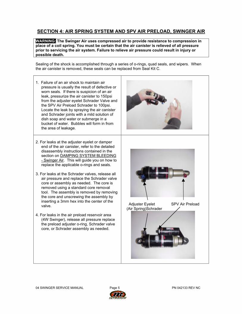
1. Failure of an air shock to maintain airpressure is usually the result of defective orworn seals. If there is suspicion of an airleak, pressurize the air canister to 150psifrom the adjuster eyelet Schrader Valve andthe SPV Air Preload Schrader to 100psi.Locate the leak by spraying the air canisterand Schrader joints with a mild solution ofdish soap and water or submerge in abucket of water. Bubbles will form in fromthe area of leakage.
2. For leaks at the adjuster eyelet or damperend of the air canister, refer to the detaileddisassembly instructions contained in thesection on DAMPING SYSTEM BLEEDING- Swinger Air. This will guide you on how toreplace the applicable o-rings and seals.
3. For leaks at the Schrader valves, release allair pressure and replace the Schrader valvecore or assembly as needed. The core isremoved using a standard core removaltool. The assembly is removed by removingthe core and unscrewing the assembly byinserting a 3mm hex into the center of thevalve.
4. For leaks in the air preload reservoir area(4W Swinger), release all pressure replacethe preload adjuster o-ring, Schrader valvecore, or Schrader assembly as needed.
Adjuster Eyelet SPV Air Preload (Air Spring)Schrader
04 SWINGER SERVICE MANUAL Page 6 PN 042133 REV NC
AIR SPRING SYSTEM AND SPV AIR PRELOAD, SWINGER AIR (CONT.)
5. If when you pressurize the air canister theshock collapses to its shortest travelposition, the shock has an air piston leakinto the negative chamber. Place the shockin the shock tester and extend it to its fulltravel. Depress the adjuster eyelet Schraderwhile the shock is extended under load. If itremains in the full travel position, refer tothe section on DAMPING SYSTEMBLEEDING - Swinger Air for instructions onservicing the air canister and piston seals.
6. If the shock returns to the short travelposition, it is not serviceable and the entireshock must be replaced.
WARNING: Attempting to service ashock with this condition could result ininjury or possible death.
04 SWINGER SERVICE MANUAL Page 7 PN 042133 REV NC
SECTION 5: COMPLETE SHOCK LESS MOUNTING HARDWARE AND COILSPRING
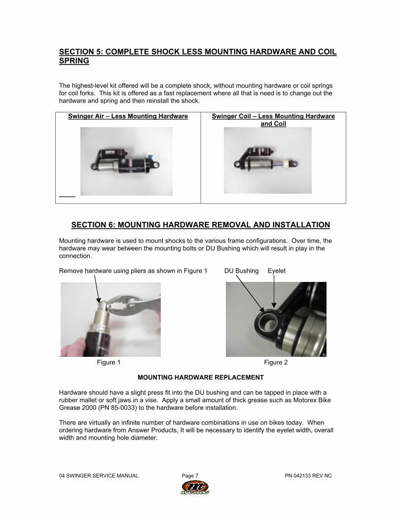
The highest-level kit offered will be a complete shock, without mounting hardware or coil springsfor coil forks. This kit is offered as a fast replacement where all that is need is to change out thehardware and spring and then reinstall the shock.
Swinger Air – Less Mounting Hardware
Swinger Coil – Less Mounting Hardwareand Coil
SECTION 6: MOUNTING HARDWARE REMOVAL AND INSTALLATION
Mounting hardware is used to mount shocks to the various frame configurations. Over time, thehardware may wear between the mounting bolts or DU Bushing which will result in play in theconnection.
Remove hardware using pliers as shown in Figure 1 DU Bushing Eyelet
. Figure 1 Figure 2
MOUNTING HARDWARE REPLACEMENT
Hardware should have a slight press fit into the DU bushing and can be tapped in place with arubber mallet or soft jaws in a vise. Apply a small amount of thick grease such as Motorex BikeGrease 2000 (PN 85-0033) to the hardware before installation.
There are virtually an infinite number of hardware combinations in use on bikes today. Whenordering hardware from Answer Products, It will be necessary to identify the eyelet width, overallwidth and mounting hole diameter.
04 SWINGER SERVICE MANUAL Page 8 PN 042133 REV NC
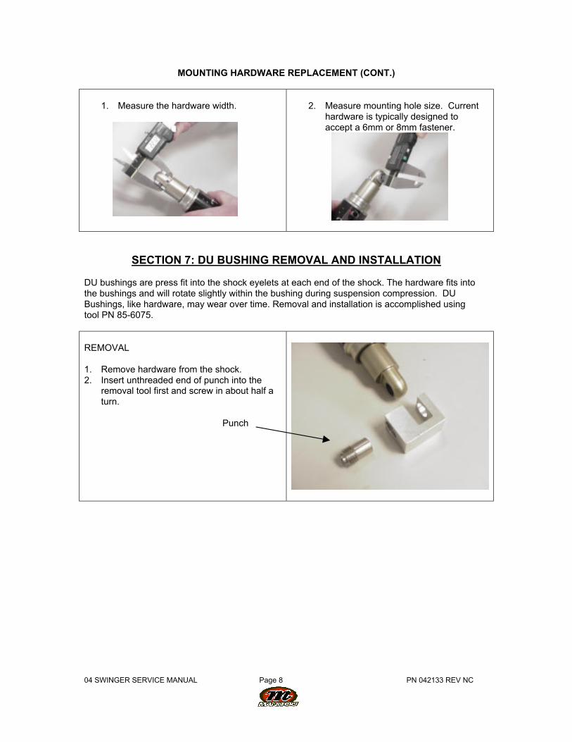
MOUNTING HARDWARE REPLACEMENT (CONT.)
1. Measure the hardware width.
2. Measure mounting hole size. Currenthardware is typically designed toaccept a 6mm or 8mm fastener.
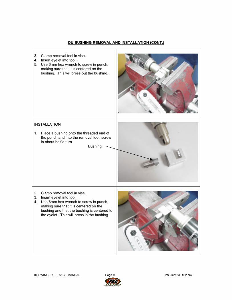
SECTION 7: DU BUSHING REMOVAL AND INSTALLATION
DU bushings are press fit into the shock eyelets at each end of the shock. The hardware fits intothe bushings and will rotate slightly within the bushing during suspension compression. DUBushings, like hardware, may wear over time. Removal and installation is accomplished usingtool PN 85-6075.
REMOVAL
1. Remove hardware from the shock.2. Insert unthreaded end of punch into the
removal tool first and screw in about half aturn.
Punch
04 SWINGER SERVICE MANUAL Page 9 PN 042133 REV NC
DU BUSHING REMOVAL AND INSTALLATION (CONT.)
3. Clamp removal tool in vise.4. Insert eyelet into tool.5. Use 6mm hex wrench to screw in punch,
making sure that it is centered on thebushing. This will press out the bushing.
INSTALLATION
1. Place a bushing onto the threaded end ofthe punch and into the removal tool; screwin about half a turn.
Bushing
2. Clamp removal tool in vise.3. Insert eyelet into tool.4. Use 6mm hex wrench to screw in punch,
making sure that it is centered on thebushing and that the bushing is centered tothe eyelet. This will press in the bushing.
04 SWINGER SERVICE MANUAL Page 10 PN 042133 REV NC
SECTION 8: RIDE KITS
Ride kits (Coil Swinger only) consist of a replacement spring of a specific spring rate that is firmeror softer depending on the rider's preference. Most manufacturers using Swinger Coil shocksvary the stock spring rate that is the standard offering based on frame size. Larger frame sizedhave higher spring rates to accommodate bigger riders. Due to the wide variety of framegeometry in use, it is left to the rider to determine if they are satisfied with their stock spring rate.
Spring rates and travel are marked on the outside of each spring.
Example: "300 X 2.75" Is a 300lb spring for a 2.75" Travel Shock
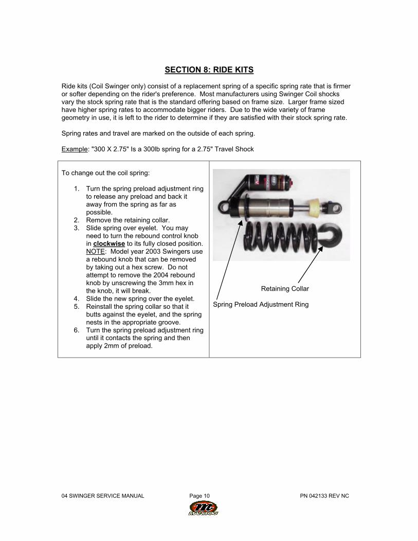
To change out the coil spring:
1. Turn the spring preload adjustment ringto release any preload and back itaway from the spring as far aspossible.
2. Remove the retaining collar.3. Slide spring over eyelet. You may
need to turn the rebound control knobin clockwise to its fully closed position.NOTE: Model year 2003 Swingers usea rebound knob that can be removedby taking out a hex screw. Do notattempt to remove the 2004 reboundknob by unscrewing the 3mm hex inthe knob, it will break.
4. Slide the new spring over the eyelet.5. Reinstall the spring collar so that it
butts against the eyelet, and the springnests in the appropriate groove.
6. Turn the spring preload adjustment ringuntil it contacts the spring and thenapply 2mm of preload.
Retaining Collar
Spring Preload Adjustment Ring
04 SWINGER SERVICE MANUAL Page 11 PN 042133 REV NC
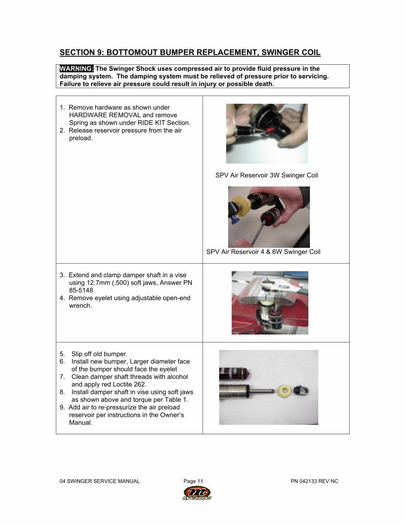
SECTION 9: BOTTOMOUT BUMPER REPLACEMENT, SWINGER COIL
WARNING: The Swinger Shock uses compressed air to provide fluid pressure in thedamping system. The damping system must be relieved of pressure prior to servicing.Failure to relieve air pressure could result in injury or possible death.
1. Remove hardware as shown underHARDWARE REMOVAL and removeSpring as shown under RIDE KIT Section.
2. Release reservoir pressure from the airpreload.
SPV Air Reservoir 3W Swinger Coil
SPV Air Reservoir 4 & 6W Swinger Coil
3. Extend and clamp damper shaft in a viseusing 12.7mm (.500) soft jaws, Answer PN85-5148
4. Remove eyelet using adjustable open-endwrench.
5. Slip off old bumper.6. Install new bumper, Larger diameter face
of the bumper should face the eyelet7. Clean damper shaft threads with alcohol
and apply red Loctite 262.8. Install damper shaft in vise using soft jaws
as shown above and torque per Table 1.9. Add air to re-pressurize the air preload
reservoir per instructions in the Owner’sManual.
04 SWINGER SERVICE MANUAL Page 12 PN 042133 REV NC
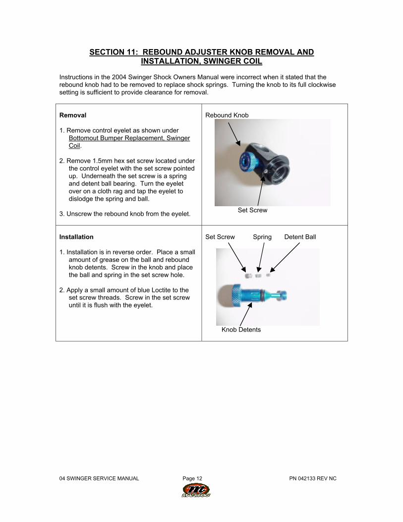
SECTION 11: REBOUND ADJUSTER KNOB REMOVAL ANDINSTALLATION, SWINGER COIL
Instructions in the 2004 Swinger Shock Owners Manual were incorrect when it stated that therebound knob had to be removed to replace shock springs. Turning the knob to its full clockwisesetting is sufficient to provide clearance for removal.
Removal
1. Remove control eyelet as shown underBottomout Bumper Replacement, SwingerCoil.
2. Remove 1.5mm hex set screw located underthe control eyelet with the set screw pointedup. Underneath the set screw is a springand detent ball bearing. Turn the eyeletover on a cloth rag and tap the eyelet todislodge the spring and ball.
3. Unscrew the rebound knob from the eyelet.
Rebound Knob
Set Screw
Installation
1. Installation is in reverse order. Place a smallamount of grease on the ball and reboundknob detents. Screw in the knob and placethe ball and spring in the set screw hole.
2. Apply a small amount of blue Loctite to theset screw threads. Screw in the set screwuntil it is flush with the eyelet.
Set Screw Spring Detent Ball
Knob Detents
04 SWINGER SERVICE MANUAL Page 13 PN 042133 REV NC
SECTION 10: DAMPING SYSTEM
The damping system controls compression and rebound rate (speed). The system also providesthe peddling platform unique to shocks with the SPV technology. The main conditions requiringservice you may encounter in regards to the damping system are leaks, a suspect SPV, brokenrebound adjuster knob, or lose damper or reservoir body.
SPV VALVE INSPECTION
If you are unable to achieve the pedaling platform after adjusting the shock per the Owner'sManual, you will need to inspect the SPV. Follow the instructions under the damping bleedingsection for the shock in question in order to inspect the SPV.
LEAKS
If oil is found to be leaking from the shock, the seals and/or o-rings that seal that suspect jointmust be serviced. Once the system has lost oil, the faulty seals must be replaced and the shockbled to restore the shock to full performance.
LOOSE DAMPER OR RESEVOIR BODY
All Swinger service can be performed without removing the damper or reservoir bodies wherethey are threaded into a machined casting. This joint is bonded in place during final assembly atthe factory. If either becomes loose during service, remove the body, and thoroughly clean thethreads on each part. Apply green Loctite the threads and use the Answer reservoir clamp PN85-6037 to tighten the bodies.
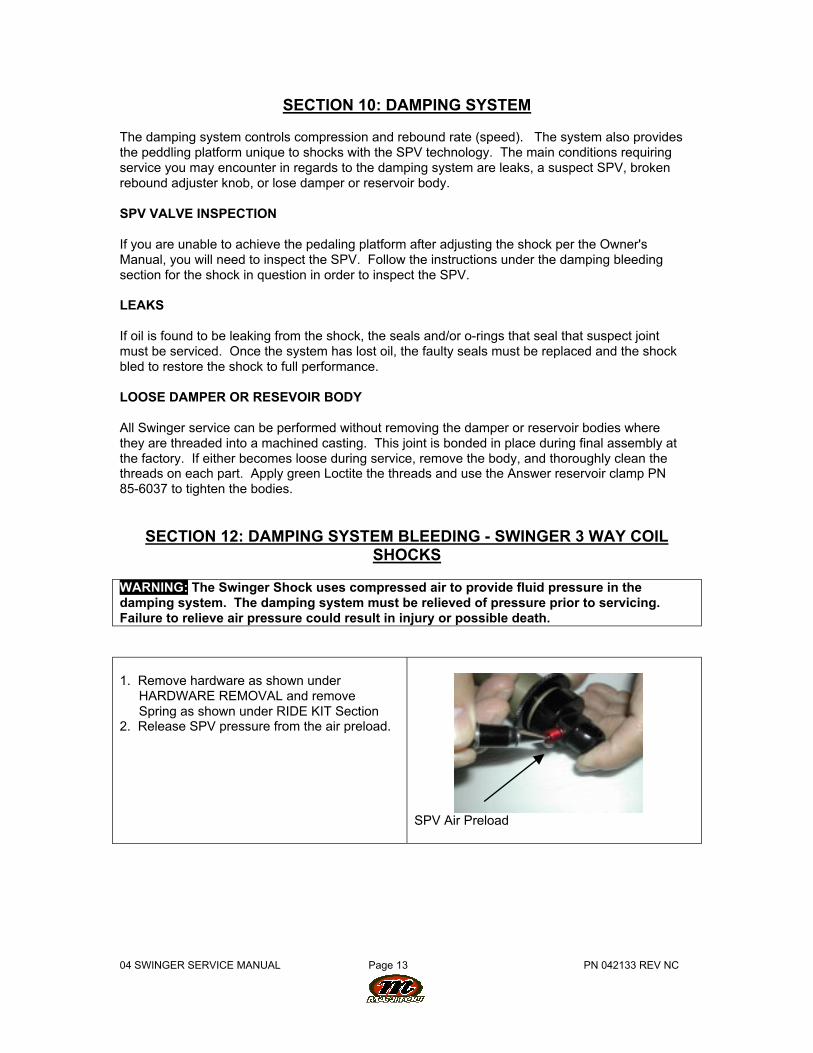
SECTION 12: DAMPING SYSTEM BLEEDING - SWINGER 3 WAY COILSHOCKS
WARNING: The Swinger Shock uses compressed air to provide fluid pressure in thedamping system. The damping system must be relieved of pressure prior to servicing.Failure to relieve air pressure could result in injury or possible death.
1. Remove hardware as shown underHARDWARE REMOVAL and removeSpring as shown under RIDE KIT Section
2. Release SPV pressure from the air preload.
SPV Air Preload
04 SWINGER SERVICE MANUAL Page 14 PN 042133 REV NC
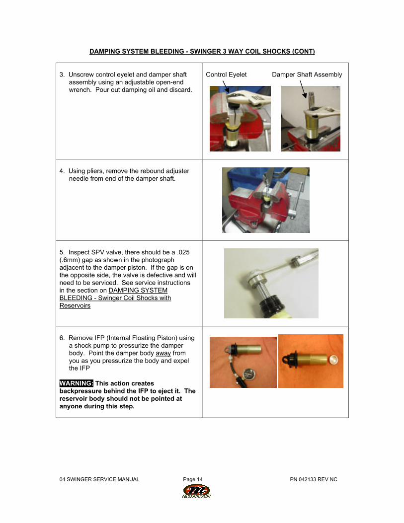
DAMPING SYSTEM BLEEDING - SWINGER 3 WAY COIL SHOCKS (CONT)
3. Unscrew control eyelet and damper shaftassembly using an adjustable open-endwrench. Pour out damping oil and discard.
Control Eyelet Damper Shaft Assembly
4. Using pliers, remove the rebound adjusterneedle from end of the damper shaft.
5. Inspect SPV valve, there should be a .025(.6mm) gap as shown in the photographadjacent to the damper piston. If the gap is onthe opposite side, the valve is defective and willneed to be serviced. See service instructionsin the section on DAMPING SYSTEMBLEEDING - Swinger Coil Shocks withReservoirs
6. Remove IFP (Internal Floating Piston) usinga shock pump to pressurize the damperbody. Point the damper body away fromyou as you pressurize the body and expelthe IFP
WARNING: This action createsbackpressure behind the IFP to eject it. Thereservoir body should not be pointed atanyone during this step.
04 SWINGER SERVICE MANUAL Page 15 PN 042133 REV NC
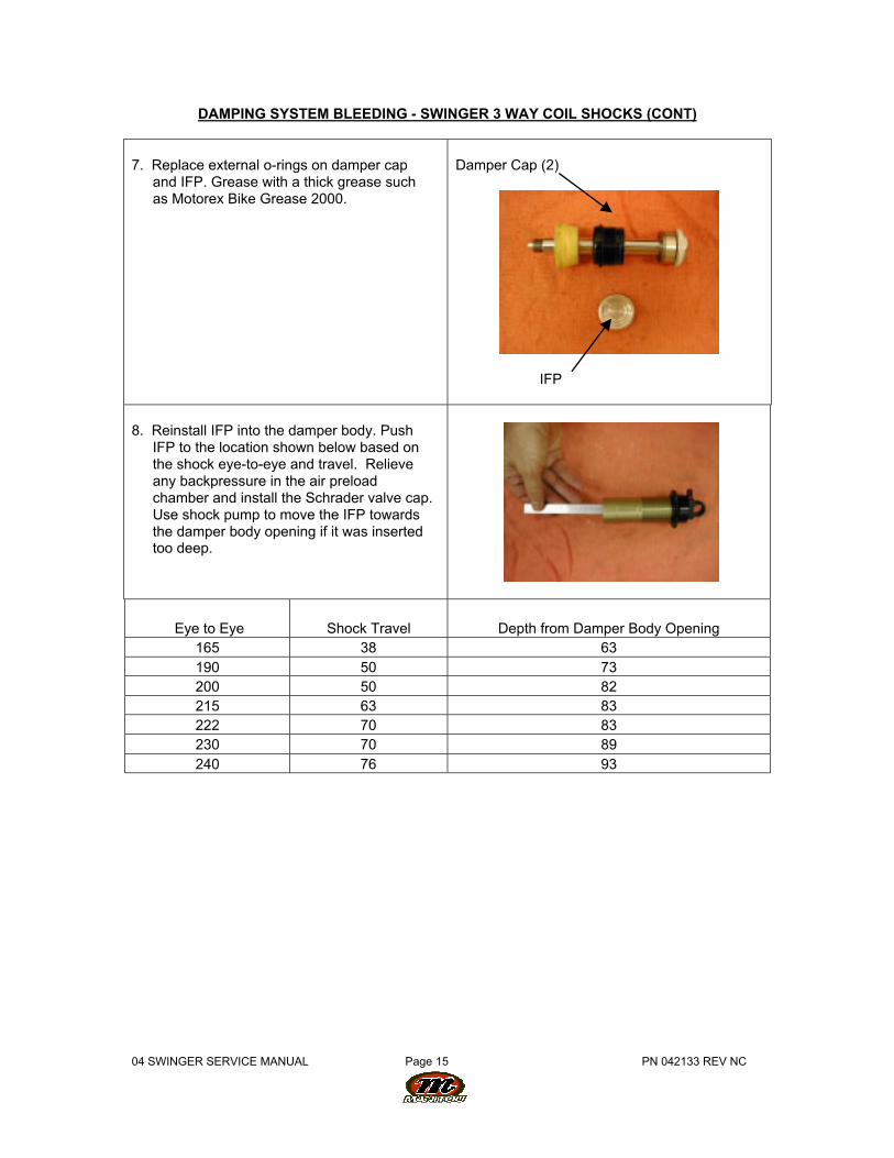
DAMPING SYSTEM BLEEDING - SWINGER 3 WAY COIL SHOCKS (CONT)
7. Replace external o-rings on damper capand IFP. Grease with a thick grease suchas Motorex Bike Grease 2000.
Damper Cap (2)
IFP
8. Reinstall IFP into the damper body. PushIFP to the location shown below based onthe shock eye-to-eye and travel. Relieveany backpressure in the air preloadchamber and install the Schrader valve cap.Use shock pump to move the IFP towardsthe damper body opening if it was insertedtoo deep.
Eye to Eye Shock Travel Depth from Damper Body Opening165 38 63190 50 73200 50 82215 63 83222 70 83230 70 89240 76 93
04 SWINGER SERVICE MANUAL Page 16 PN 042133 REV NC
DAMPING SYSTEM BLEEDING - SWINGER 3 WAY COIL SHOCKS (CONT)
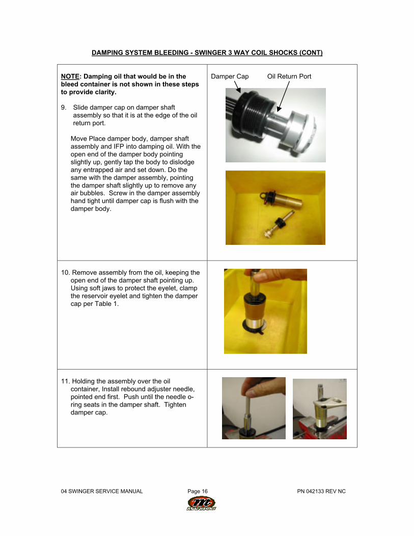
NOTE: Damping oil that would be in thebleed container is not shown in these stepsto provide clarity.
9. Slide damper cap on damper shaftassembly so that it is at the edge of the oilreturn port.
Move Place damper body, damper shaftassembly and IFP into damping oil. With theopen end of the damper body pointingslightly up, gently tap the body to dislodgeany entrapped air and set down. Do thesame with the damper assembly, pointingthe damper shaft slightly up to remove anyair bubbles. Screw in the damper assemblyhand tight until damper cap is flush with thedamper body.
Damper Cap Oil Return Port
10. Remove assembly from the oil, keeping theopen end of the damper shaft pointing up.Using soft jaws to protect the eyelet, clampthe reservoir eyelet and tighten the dampercap per Table 1.
11. Holding the assembly over the oilcontainer, Install rebound adjuster needle,pointed end first. Push until the needle o-ring seats in the damper shaft. Tightendamper cap.
04 SWINGER SERVICE MANUAL Page 17 PN 042133 REV NC
DAMPING SYSTEM BLEEDING - SWINGER 3 WAY COIL SHOCKS (CONT)
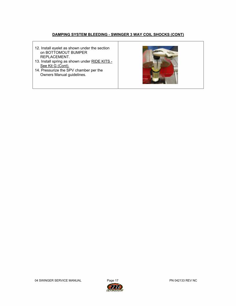
12. Install eyelet as shown under the sectionon BOTTOMOUT BUMPERREPLACEMENT.
13. Install spring as shown under RIDE KITS -See Kit G (Cont).
14. Pressurize the SPV chamber per theOwners Manual guidelines.
04 SWINGER SERVICE MANUAL Page 18 PN 042133 REV NC
SECTION 13: DAMPING SYSTEM BLEEDING - SWINGER 4 & 6 WAY COILSHOCKS
WARNING: The Swinger Shock uses compressed air to provide fluid pressure in thedamping system. The damping system must be relieved of pressure prior to servicing.Failure to relieve air pressure could result in injury or possible death.
NOTE: Leaks from Low/High Speed Adjusters on Swinger 6 Way Shocks. The 6 Way adjusterknobs are adjusted using a 3mm (Early 2004 Models) or 2mm (Late 2004 Models) hex. If toomuch force is applied then the knob is adjusted counterclockwise, the adjuster needles may stripout and result in an oil leak. If this occurs during adjustment and the shock has not beencompressed, the adjusters can be replaced without a complete teardown and bleeding of theshock. Follow the instructions in Step 10.
1. Remove hardware as shown underHARDWARE REMOVAL and removeSpring as shown under RIDE KIT Section
2. Release reservoir pressure from the airpreload.
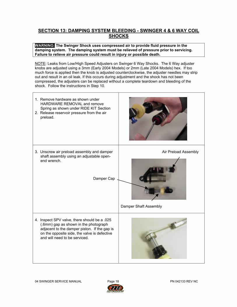
3. Unscrew air preload assembly and dampershaft assembly using an adjustable open-end wrench.
Damper Cap
Air Preload Assembly
Damper Shaft Assembly
4. Inspect SPV valve, there should be a .025(.6mm) gap as shown in the photographadjacent to the damper piston. If the gap ison the opposite side, the valve is defectiveand will need to be serviced.
04 SWINGER SERVICE MANUAL Page 19 PN 042133 REV NC
DAMPING SYSTEM BLEEDING - SWINGER 4 & 6 WAY COIL SHOCKS (CONT)
5. If it is necessary to remove the valve, clampthe damper shaft using soft jaws and loosenthe damper piston bolt. Grasp the damperbolt, piston, SPV, and SPV backing plateand remove as a set from the damper shaft.
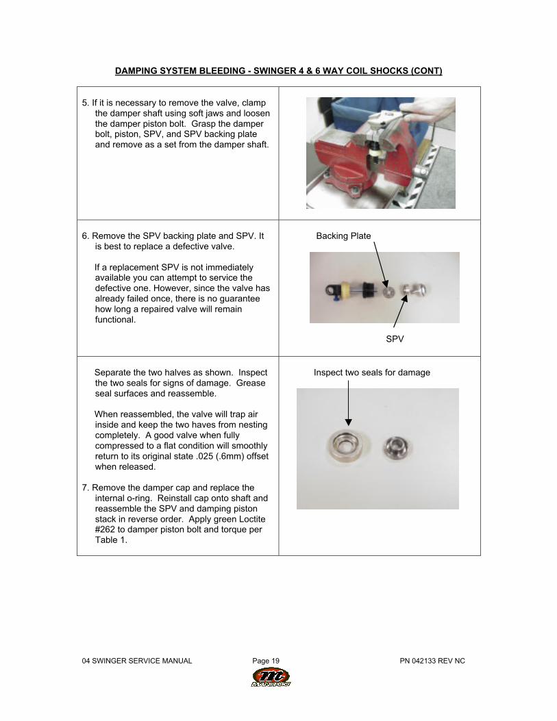
6. Remove the SPV backing plate and SPV. Itis best to replace a defective valve.
If a replacement SPV is not immediatelyavailable you can attempt to service thedefective one. However, since the valve hasalready failed once, there is no guaranteehow long a repaired valve will remainfunctional.
Backing Plate
SPV
Separate the two halves as shown. Inspectthe two seals for signs of damage. Greaseseal surfaces and reassemble.
When reassembled, the valve will trap airinside and keep the two haves from nestingcompletely. A good valve when fullycompressed to a flat condition will smoothlyreturn to its original state .025 (.6mm) offsetwhen released.
7. Remove the damper cap and replace theinternal o-ring. Reinstall cap onto shaft andreassemble the SPV and damping pistonstack in reverse order. Apply green Loctite#262 to damper piston bolt and torque perTable 1.
Inspect two seals for damage
04 SWINGER SERVICE MANUAL Page 20 PN 042133 REV NC
DAMPING SYSTEM BLEEDING - SWINGER 4 & 6 WAY COIL SHOCKS (CONT)
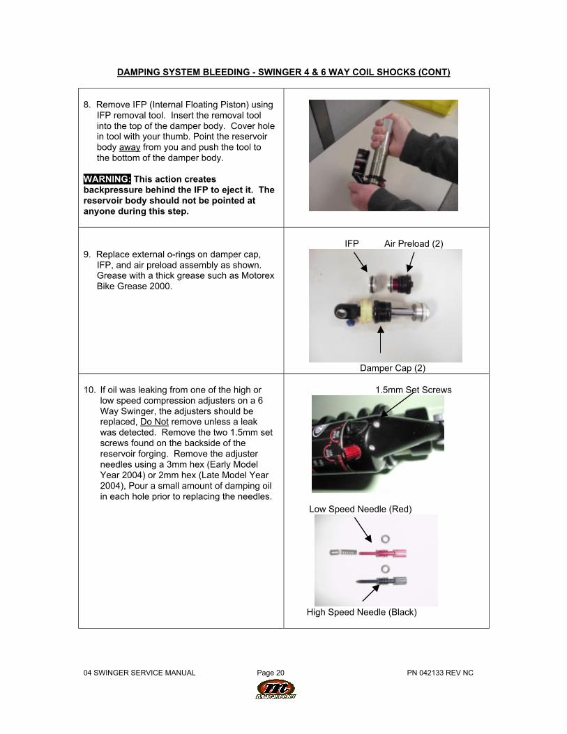
8. Remove IFP (Internal Floating Piston) usingIFP removal tool. Insert the removal toolinto the top of the damper body. Cover holein tool with your thumb. Point the reservoirbody away from you and push the tool tothe bottom of the damper body.
WARNING: This action createsbackpressure behind the IFP to eject it. Thereservoir body should not be pointed atanyone during this step.
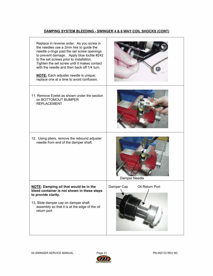
9. Replace external o-rings on damper cap,IFP, and air preload assembly as shown.Grease with a thick grease such as MotorexBike Grease 2000.
IFP Air Preload (2)
Damper Cap (2)
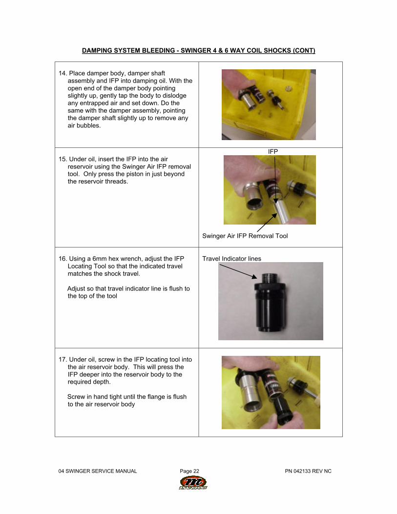
10. If oil was leaking from one of the high orlow speed compression adjusters on a 6Way Swinger, the adjusters should bereplaced, Do Not remove unless a leakwas detected. Remove the two 1.5mm setscrews found on the backside of thereservoir forging. Remove the adjusterneedles using a 3mm hex (Early ModelYear 2004) or 2mm hex (Late Model Year2004), Pour a small amount of damping oilin each hole prior to replacing the needles.
1.5mm Set Screws
Low Speed Needle (Red)
High Speed Needle (Black)
04 SWINGER SERVICE MANUAL Page 21 PN 042133 REV NC
DAMPING SYSTEM BLEEDING - SWINGER 4 & 6 WAY COIL SHOCKS (CONT)
Replace in reverse order. As you screw inthe needles use a 2mm hex to guide theneedle o-rings past the set screw openingsto prevent damage. Apply blue loctite #242to the set screws prior to installation.Tighten the set screw until it makes contactwith the needle and then back off 1/4 turn.
NOTE: Each adjuster needle is unique;replace one at a time to avoid confusion.
11. Remove Eyelet as shown under the sectionon BOTTOMOUT BUMPERREPLACEMENT
12. Using pliers, remove the rebound adjusterneedle from end of the damper shaft.
Damper Needle
NOTE: Damping oil that would be in thebleed container is not shown in these stepsto provide clarity.
13. Slide damper cap on damper shaftassembly so that it is at the edge of the oilreturn port
Damper Cap Oil Return Port
04 SWINGER SERVICE MANUAL Page 22 PN 042133 REV NC
DAMPING SYSTEM BLEEDING - SWINGER 4 & 6 WAY COIL SHOCKS (CONT)
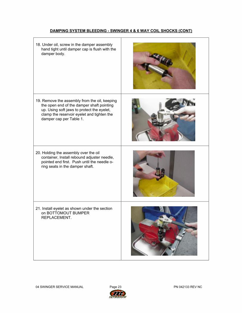
14. Place damper body, damper shaftassembly and IFP into damping oil. With theopen end of the damper body pointingslightly up, gently tap the body to dislodgeany entrapped air and set down. Do thesame with the damper assembly, pointingthe damper shaft slightly up to remove anyair bubbles.
15. Under oil, insert the IFP into the airreservoir using the Swinger Air IFP removaltool. Only press the piston in just beyondthe reservoir threads.
IFP
Swinger Air IFP Removal Tool
16. Using a 6mm hex wrench, adjust the IFPLocating Tool so that the indicated travelmatches the shock travel.
Adjust so that travel indicator line is flush tothe top of the tool
Travel Indicator lines
17. Under oil, screw in the IFP locating tool intothe air reservoir body. This will press theIFP deeper into the reservoir body to therequired depth.
Screw in hand tight until the flange is flushto the air reservoir body
04 SWINGER SERVICE MANUAL Page 23 PN 042133 REV NC
DAMPING SYSTEM BLEEDING - SWINGER 4 & 6 WAY COIL SHOCKS (CONT)
18. Under oil, screw in the damper assemblyhand tight until damper cap is flush with thedamper body.
19. Remove the assembly from the oil, keepingthe open end of the damper shaft pointingup. Using soft jaws to protect the eyelet,clamp the reservoir eyelet and tighten thedamper cap per Table 1.
20. Holding the assembly over the oilcontainer, Install rebound adjuster needle,pointed end first. Push until the needle o-ring seats in the damper shaft.
21. Install eyelet as shown under the sectionon BOTTOMOUT BUMPERREPLACEMENT.
04 SWINGER SERVICE MANUAL Page 24 PN 042133 REV NC
DAMPING SYSTEM BLEEDING - SWINGER 4 & 6 WAY COIL SHOCKS (CONT)
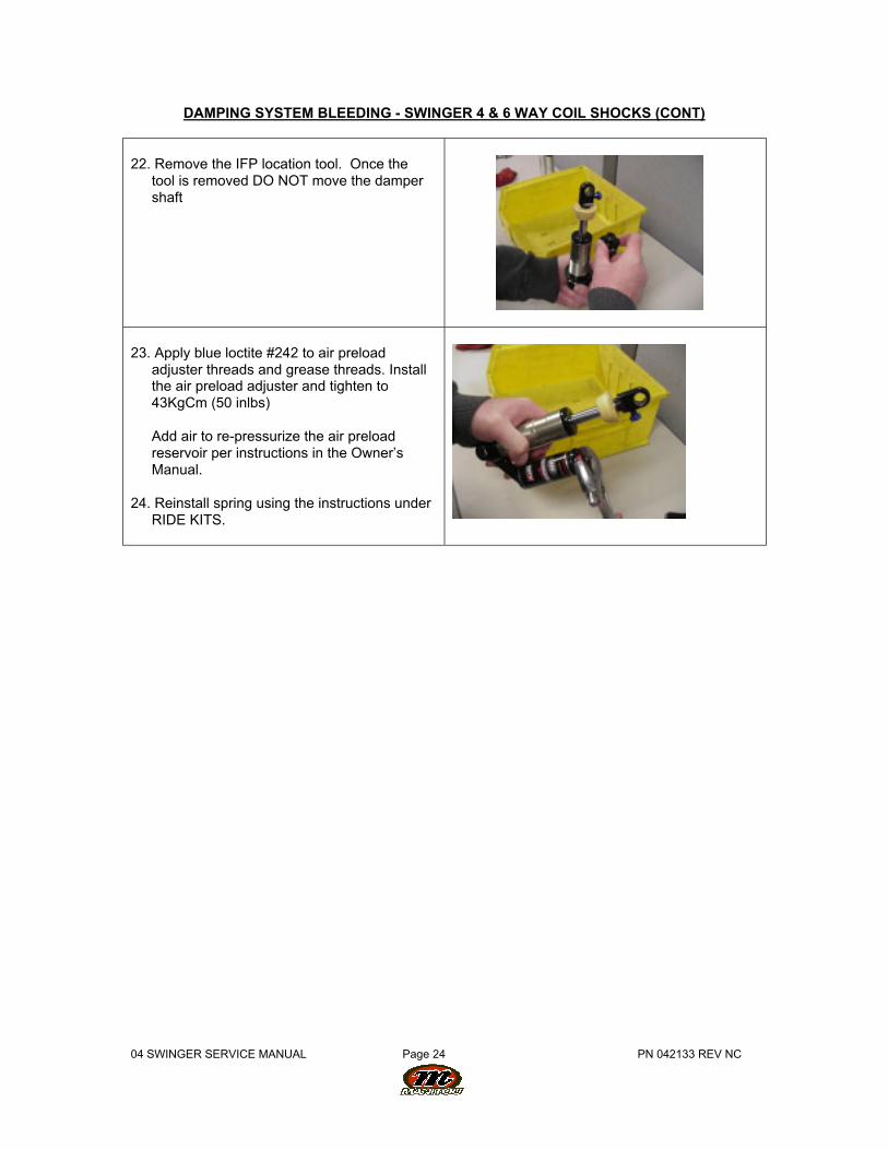
22. Remove the IFP location tool. Once thetool is removed DO NOT move the dampershaft
23. Apply blue loctite #242 to air preloadadjuster threads and grease threads. Installthe air preload adjuster and tighten to43KgCm (50 inlbs)
Add air to re-pressurize the air preloadreservoir per instructions in the Owner’sManual.
24. Reinstall spring using the instructions underRIDE KITS.
04 SWINGER SERVICE MANUAL Page 25 PN 042133 REV NC
SECTION 14: DAMPING SYSTEM BLEEDING - SWINGER 3 WAY AIRSHOCKS
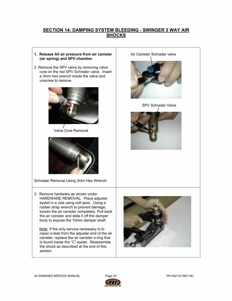
1. Release All air pressure from air canister(air spring) and SPV chamber.
2. Remove the SPV valve by removing valvecore on the red SPV Schrader valve. Inserta 3mm hex wrench inside the valve andunscrew to remove.
Valve Core Removal
Schrader Removal Using 3mm Hex Wrench
Air Canister Schrader valve
SPV Schrader Valve
3. Remove hardware as shown underHARDWARE REMOVAL. Place adjustereyelet in a vise using soft jaws. Using arubber strap wrench to prevent damage,loosen the air canister completely. Pull backthe air canister and slide it off the damperbody to expose the 10mm damper shaft.
Note: If the only service necessary is torepair a leak from the adjuster end of the aircanister, replace the air canister o-ring thatis found inside the “C” eyelet. Reassemblethe shock as described at the end of thissection
04 SWINGER SERVICE MANUAL Page 26 PN 042133 REV NC
DAMPING SYSTEM BLEEDING - SWINGER 3 WAY AIR SHOCKS (CONT.)
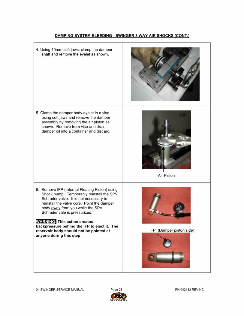
4. Using 10mm soft jaws, clamp the dampershaft and remove the eyelet as shown.
5. Clamp the damper body eyelet in a viseusing soft jaws and remove the damperassembly by removing the air piston asshown. Remove from vise and draindamper oil into a container and discard.
Air Piston
6. Remove IFP (Internal Floating Piston) usingShock pump. Temporarily reinstall the SPVSchrader valve. It is not necessary toreinstall the valve core. Point the damperbody away from you while the SPVSchrader vale is pressurized.
WARNING: This action createsbackpressure behind the IFP to eject it. Thereservoir body should not be pointed atanyone during this step
IFP (Damper piston side)
04 SWINGER SERVICE MANUAL Page 27 PN 042133 REV NC
DAMPING SYSTEM BLEEDING - SWINGER 3 WAY AIR SHOCKS (CONT.)
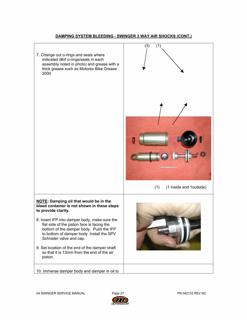
7. Change out o-rings and seals whereindicated (#of o-rings/seals in eachassembly noted in photo) and grease with athick grease such as Motorex Bike Grease2000
(3) (1)
(1) (1 inside and 1outside)
NOTE: Damping oil that would be in thebleed container is not shown in these stepsto provide clarity.
8. Insert IFP into damper body, make sure theflat side of the piston face is facing thebottom of the damper body. Push the IFPto bottom of damper body. Install the SPVSchrader valve and cap.
9. Set location of the end of the damper shaftso that it is 13mm from the end of the airpiston.
10. Immerse damper body and damper in oil to
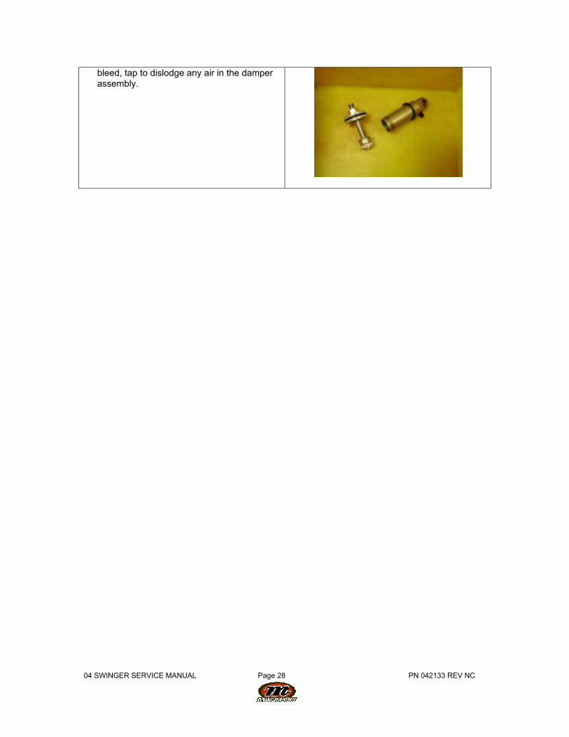
04 SWINGER SERVICE MANUAL Page 28 PN 042133 REV NC
bleed, tap to dislodge any air in the damperassembly.
04 SWINGER SERVICE MANUAL Page 29 PN 042133 REV NC
DAMPING SYSTEM BLEEDING - SWINGER 3 WAY AIR SHOCKS (CONT.)
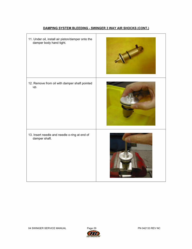
11. Under oil, install air piston/damper onto thedamper body hand tight.
12. Remove from oil with damper shaft pointedup.
13. Insert needle and needle o-ring at end ofdamper shaft.
04 SWINGER SERVICE MANUAL Page 30 PN 042133 REV NC
DAMPING SYSTEM BLEEDING - SWINGER 3 WAY AIR SHOCKS (CONT.)
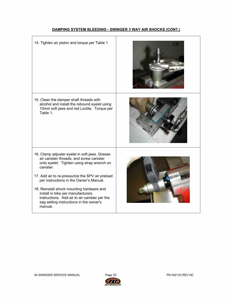
14. Tighten air piston and torque per Table 1
15. Clean the damper shaft threads withalcohol and install the rebound eyelet using10mm soft jaws and red Loctite. Torque perTable 1.
16. Clamp adjuster eyelet in soft jaws. Greaseair canister threads, and screw canisteronto eyelet. Tighten using strap wrench oncanister.
17. Add air to re-pressurize the SPV air preloadper instructions in the Owner’s Manual.
18. Reinstall shock mounting hardware andinstall in bike per manufacturersinstructions. Add air to air canister per thesag setting instructions in the owner'smanual.
04 SWINGER SERVICE MANUAL Page 31 PN 042133 REV NC
SECTION 15: DAMPING SYSTEM BLEEDING - SWINGER 4 WAY AIRSHOCKS
WARNING: The Swinger Air uses compressed air to provide resistance to compression inplace of a coil spring. You must be certain that the air canister is relieved of all pressureprior to servicing the air system. Failure to relieve air pressure could result in injury orpossible death.
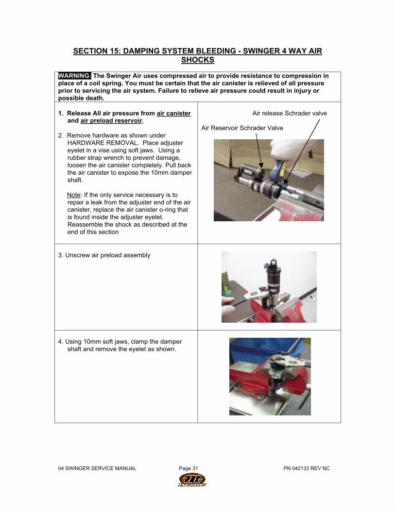
1. Release All air pressure from air canisterand air preload reservoir.
2. Remove hardware as shown underHARDWARE REMOVAL. Place adjustereyelet in a vise using soft jaws. Using arubber strap wrench to prevent damage,loosen the air canister completely. Pull backthe air canister to expose the 10mm dampershaft.
Note: If the only service necessary is torepair a leak from the adjuster end of the aircanister, replace the air canister o-ring thatis found inside the adjuster eyelet.Reassemble the shock as described at theend of this section
Air release Schrader valve
Air Reservoir Schrader Valve
3. Unscrew air preload assembly
4. Using 10mm soft jaws, clamp the dampershaft and remove the eyelet as shown.
04 SWINGER SERVICE MANUAL Page 32 PN 042133 REV NC
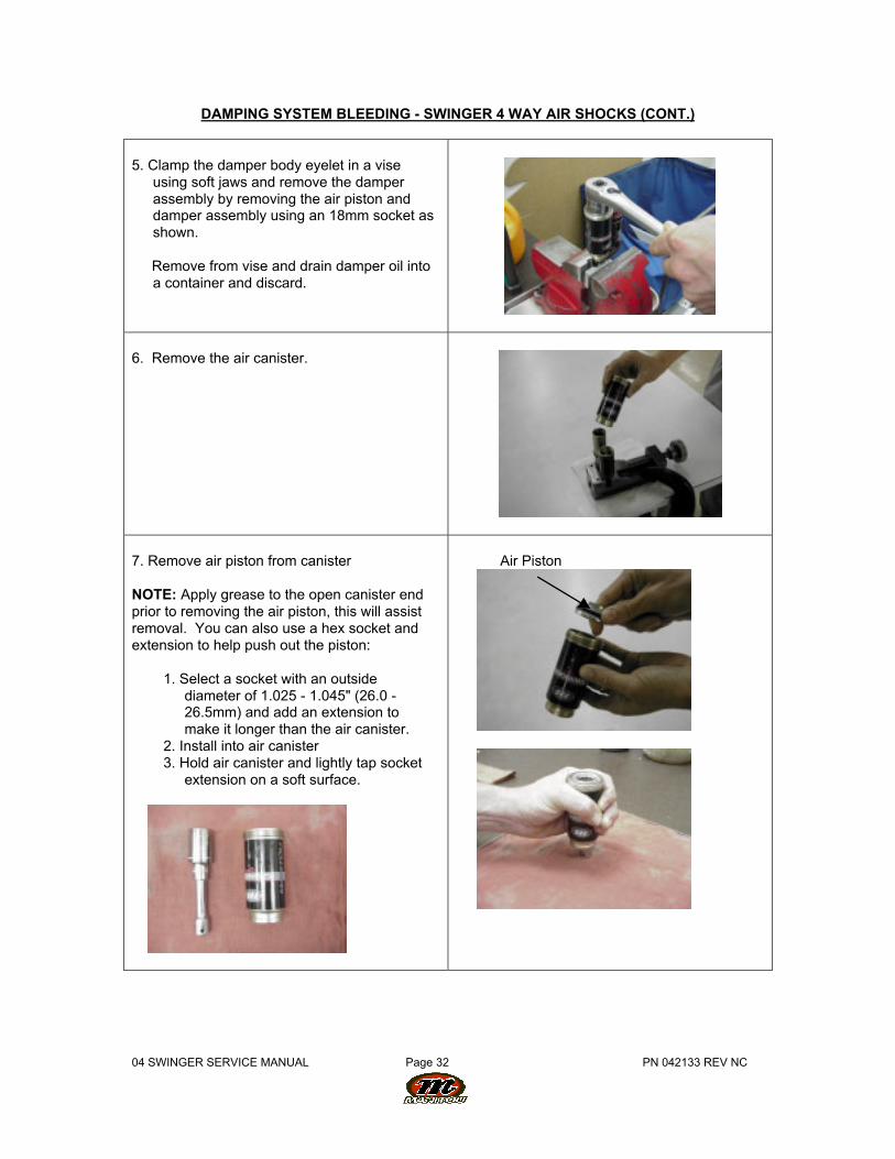
DAMPING SYSTEM BLEEDING - SWINGER 4 WAY AIR SHOCKS (CONT.)
5. Clamp the damper body eyelet in a viseusing soft jaws and remove the damperassembly by removing the air piston anddamper assembly using an 18mm socket asshown.
Remove from vise and drain damper oil intoa container and discard.
6. Remove the air canister.
7. Remove air piston from canister
NOTE: Apply grease to the open canister endprior to removing the air piston, this will assistremoval. You can also use a hex socket andextension to help push out the piston:
1. Select a socket with an outsidediameter of 1.025 - 1.045" (26.0 -26.5mm) and add an extension tomake it longer than the air canister.
2. Install into air canister3. Hold air canister and lightly tap socket
extension on a soft surface.
Air Piston
04 SWINGER SERVICE MANUAL Page 33 PN 042133 REV NC
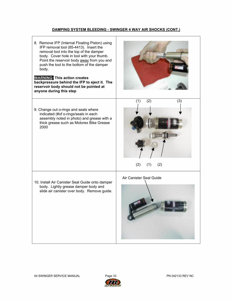
DAMPING SYSTEM BLEEDING - SWINGER 4 WAY AIR SHOCKS (CONT.)
8. Remove IFP (Internal Floating Piston) usingIFP removal tool (85-4413). Insert theremoval tool into the top of the damperbody. Cover hole in tool with your thumb.Point the reservoir body away from you andpush the tool to the bottom of the damperbody.
WARNING: This action createsbackpressure behind the IFP to eject it. Thereservoir body should not be pointed atanyone during this step
9. Change out o-rings and seals whereindicated (#of o-rings/seals in eachassembly noted in photo) and grease with athick grease such as Motorex Bike Grease2000
(1) (2) (3)
(2) (1) (2)
10. Install Air Canister Seal Guide onto damperbody. Lightly grease damper body andslide air canister over body. Remove guide.
Air Canister Seal Guide

04 SWINGER SERVICE MANUAL Page 34 PN 042133 REV NC
DAMPING SYSTEM BLEEDING - SWINGER 4 WAY AIR SHOCKS (CONT.)
11. Grease inside of air canister and install aircanister as shown. The seal end of the airpiston is installed first.
12. Slide air piston on damper shaft assemblyso that it is at the edge of the oil return porton the shaft.
Oil Return Port
NOTE: Damping oil that would be in thebleed container is not shown in these stepsto provide clarity.
13. Place damper body, damper shaftassembly and IFP into damping oil.
14. With the open end of the damper bodypointing slightly up, gently tap the body todislodge any entrapped air and set down.
15. Do the same with the damper assembly,pointing the damper shaft slightly up toremove any air bubbles.
04 SWINGER SERVICE MANUAL Page 35 PN 042133 REV NC
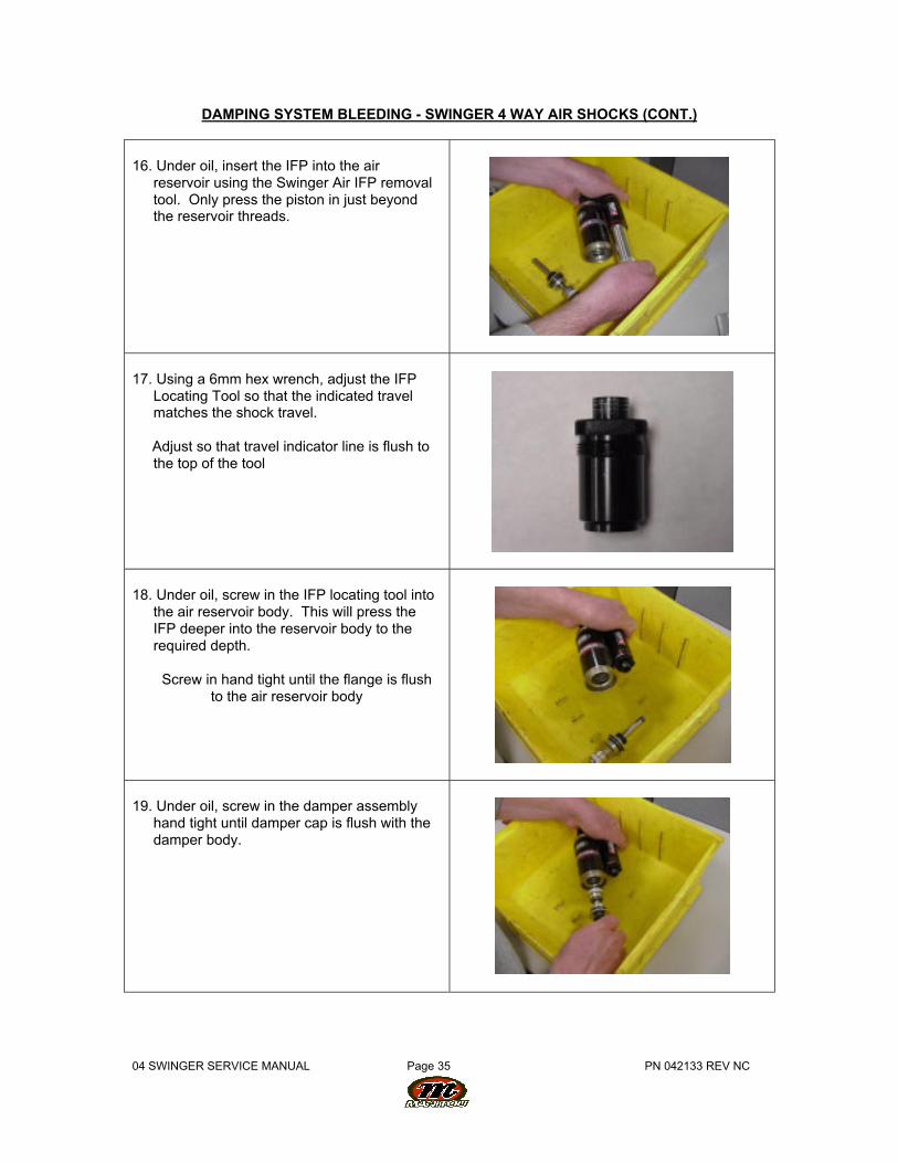
DAMPING SYSTEM BLEEDING - SWINGER 4 WAY AIR SHOCKS (CONT.)
16. Under oil, insert the IFP into the airreservoir using the Swinger Air IFP removaltool. Only press the piston in just beyondthe reservoir threads.
17. Using a 6mm hex wrench, adjust the IFPLocating Tool so that the indicated travelmatches the shock travel.
Adjust so that travel indicator line is flush tothe top of the tool
18. Under oil, screw in the IFP locating tool intothe air reservoir body. This will press theIFP deeper into the reservoir body to therequired depth.
Screw in hand tight until the flange is flushto the air reservoir body
19. Under oil, screw in the damper assemblyhand tight until damper cap is flush with thedamper body.
04 SWINGER SERVICE MANUAL Page 36 PN 042133 REV NC
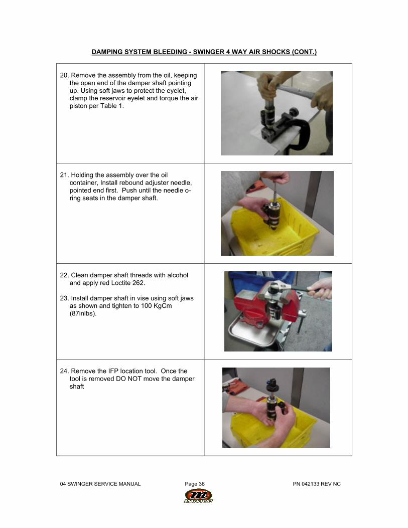
DAMPING SYSTEM BLEEDING - SWINGER 4 WAY AIR SHOCKS (CONT.)
20. Remove the assembly from the oil, keepingthe open end of the damper shaft pointingup. Using soft jaws to protect the eyelet,clamp the reservoir eyelet and torque the airpiston per Table 1.
21. Holding the assembly over the oilcontainer, Install rebound adjuster needle,pointed end first. Push until the needle o-ring seats in the damper shaft.
22. Clean damper shaft threads with alcoholand apply red Loctite 262.
23. Install damper shaft in vise using soft jawsas shown and tighten to 100 KgCm(87inlbs).
24. Remove the IFP location tool. Once thetool is removed DO NOT move the dampershaft
04 SWINGER SERVICE MANUAL Page 37 PN 042133 REV NC
DAMPING SYSTEM BLEEDING - SWINGER 4 WAY AIR SHOCKS (CONT.)
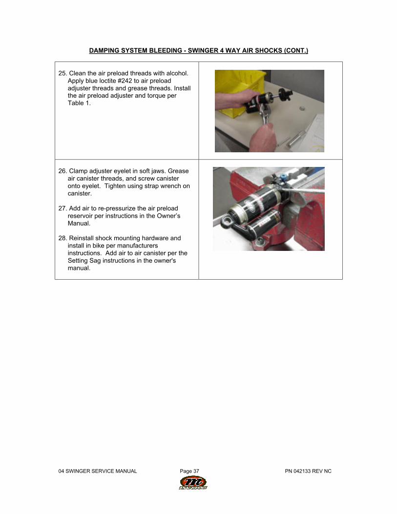
25. Clean the air preload threads with alcohol.Apply blue loctite #242 to air preloadadjuster threads and grease threads. Installthe air preload adjuster and torque perTable 1.
26. Clamp adjuster eyelet in soft jaws. Greaseair canister threads, and screw canisteronto eyelet. Tighten using strap wrench oncanister.
27. Add air to re-pressurize the air preloadreservoir per instructions in the Owner’sManual.
28. Reinstall shock mounting hardware andinstall in bike per manufacturersinstructions. Add air to air canister per theSetting Sag instructions in the owner'smanual.
04 SWINGER SERVICE MANUAL Page 38 PN 042133 REV NC
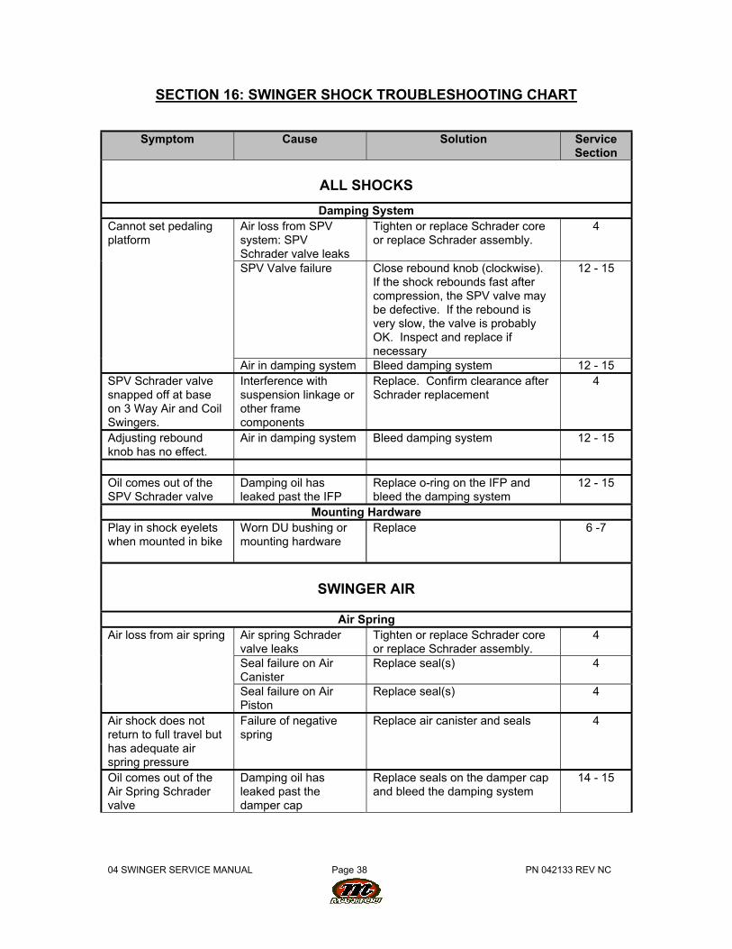
SECTION 16: SWINGER SHOCK TROUBLESHOOTING CHART
Symptom Cause Solution ServiceSection
ALL SHOCKS
Damping SystemAir loss from SPVsystem: SPVSchrader valve leaks
Tighten or replace Schrader coreor replace Schrader assembly.
4
SPV Valve failure Close rebound knob (clockwise).If the shock rebounds fast aftercompression, the SPV valve maybe defective. If the rebound isvery slow, the valve is probablyOK. Inspect and replace ifnecessary
12 - 15
Cannot set pedalingplatform
Air in damping system Bleed damping system 12 - 15SPV Schrader valvesnapped off at baseon 3 Way Air and CoilSwingers.
Interference withsuspension linkage orother framecomponents
Replace. Confirm clearance afterSchrader replacement
4
Adjusting reboundknob has no effect.
Air in damping system Bleed damping system 12 - 15
Oil comes out of theSPV Schrader valve
Damping oil hasleaked past the IFP
Replace o-ring on the IFP andbleed the damping system
12 - 15
Mounting HardwarePlay in shock eyeletswhen mounted in bike
Worn DU bushing ormounting hardware
Replace 6 -7
SWINGER AIR
Air SpringAir spring Schradervalve leaks
Tighten or replace Schrader coreor replace Schrader assembly.
4
Seal failure on AirCanister
Replace seal(s) 4
Air loss from air spring
Seal failure on AirPiston
Replace seal(s) 4
Air shock does notreturn to full travel buthas adequate airspring pressure
Failure of negativespring
Replace air canister and seals 4
Oil comes out of theAir Spring Schradervalve
Damping oil hasleaked past thedamper cap
Replace seals on the damper capand bleed the damping system
14 - 15
04 SWINGER SERVICE MANUAL Page 39 PN 042133 REV NC
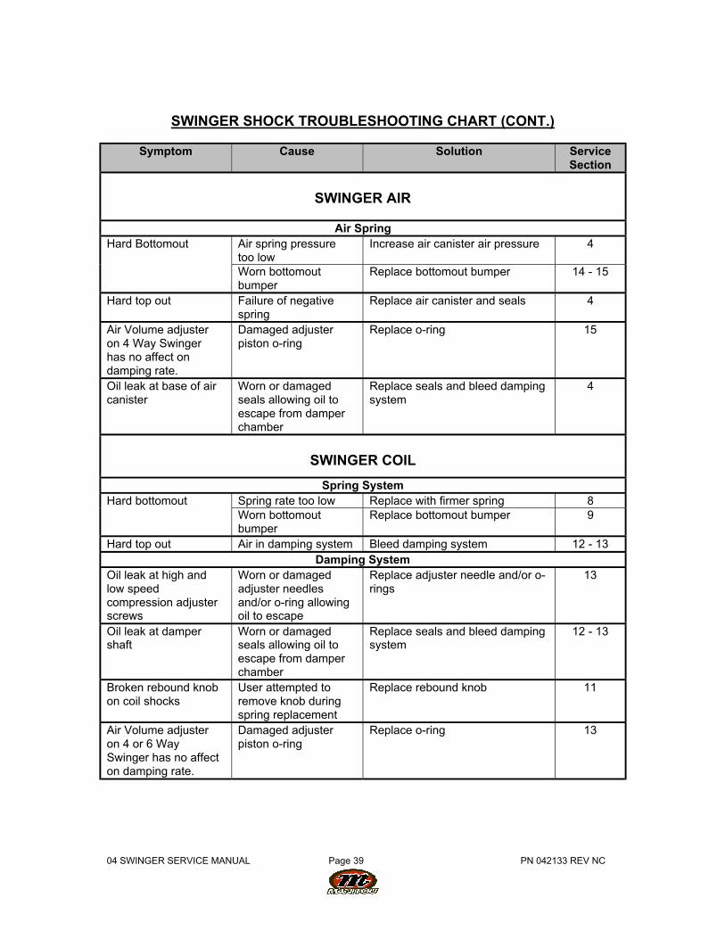
SWINGER SHOCK TROUBLESHOOTING CHART (CONT.)
Symptom Cause Solution ServiceSection
SWINGER AIR
Air SpringAir spring pressuretoo low
Increase air canister air pressure 4Hard Bottomout
Worn bottomoutbumper
Replace bottomout bumper 14 - 15
Hard top out Failure of negativespring
Replace air canister and seals 4
Air Volume adjusteron 4 Way Swingerhas no affect ondamping rate.
Damaged adjusterpiston o-ring
Replace o-ring 15
Oil leak at base of aircanister
Worn or damagedseals allowing oil toescape from damperchamber
Replace seals and bleed dampingsystem
4
SWINGER COIL
Spring SystemSpring rate too low Replace with firmer spring 8Hard bottomoutWorn bottomoutbumper
Replace bottomout bumper 9
Hard top out Air in damping system Bleed damping system 12 - 13Damping System
Oil leak at high andlow speedcompression adjusterscrews
Worn or damagedadjuster needlesand/or o-ring allowingoil to escape
Replace adjuster needle and/or o-rings
13
Oil leak at dampershaft
Worn or damagedseals allowing oil toescape from damperchamber
Replace seals and bleed dampingsystem
12 - 13
Broken rebound knobon coil shocks
User attempted toremove knob duringspring replacement
Replace rebound knob 11
Air Volume adjusteron 4 or 6 WaySwinger has no affecton damping rate.
Damaged adjusterpiston o-ring
Replace o-ring 13
04 SWINGER SERVICE MANUAL Page 40 PN 042133 REV NC
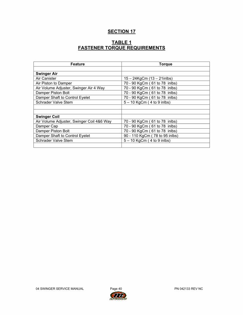
SECTION 17
TABLE 1FASTENER TORQUE REQUIREMENTS
Feature Torque
Swinger AirAir Canister 15 – 24KgCm (13 – 21inlbs)Air Piston to Damper 70 - 90 KgCm ( 61 to 78 inlbs)Air Volume Adjuster, Swinger Air 4 Way 70 - 90 KgCm ( 61 to 78 inlbs)Damper Piston Bolt 70 - 90 KgCm ( 61 to 78 inlbs)Damper Shaft to Control Eyelet 70 - 90 KgCm ( 61 to 78 inlbs)Schrader Valve Stem 5 – 10 KgCm ( 4 to 9 inlbs)
Swinger CoilAir Volume Adjuster, Swinger Coil 4&6 Way 70 - 90 KgCm ( 61 to 78 inlbs)Damper Cap 70 - 90 KgCm ( 61 to 78 inlbs)Damper Piston Bolt 70 - 90 KgCm ( 61 to 78 inlbs)Damper Shaft to Control Eyelet 90 - 110 KgCm ( 78 to 95 inlbs)Schrader Valve Stem 5 – 10 KgCm ( 4 to 9 inlbs)
04 SWINGER SERVICE MANUAL Page 41 PN 042133 REV NC
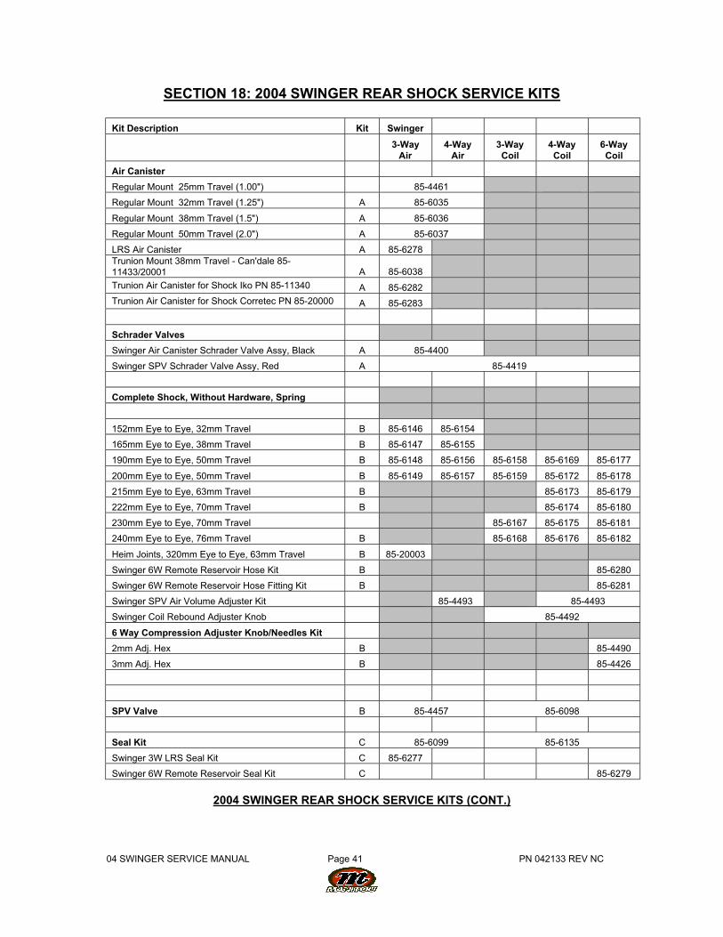
SECTION 18: 2004 SWINGER REAR SHOCK SERVICE KITS
Kit Description Kit Swinger
3-Way
Air4-Way
Air3-WayCoil
4-WayCoil
6-WayCoil
Air Canister
Regular Mount 25mm Travel (1.00") 85-4461
Regular Mount 32mm Travel (1.25") A 85-6035
Regular Mount 38mm Travel (1.5") A 85-6036
Regular Mount 50mm Travel (2.0") A 85-6037
LRS Air Canister A 85-6278 Trunion Mount 38mm Travel - Can'dale 85-11433/20001 A 85-6038
Trunion Air Canister for Shock Iko PN 85-11340 A 85-6282
Trunion Air Canister for Shock Corretec PN 85-20000 A 85-6283
Schrader Valves
Swinger Air Canister Schrader Valve Assy, Black A 85-4400
Swinger SPV Schrader Valve Assy, Red A 85-4419
Complete Shock, Without Hardware, Spring
152mm Eye to Eye, 32mm Travel B 85-6146 85-6154
165mm Eye to Eye, 38mm Travel B 85-6147 85-6155
190mm Eye to Eye, 50mm Travel B 85-6148 85-6156 85-6158 85-6169 85-6177
200mm Eye to Eye, 50mm Travel B 85-6149 85-6157 85-6159 85-6172 85-6178
215mm Eye to Eye, 63mm Travel B 85-6173 85-6179
222mm Eye to Eye, 70mm Travel B 85-6174 85-6180
230mm Eye to Eye, 70mm Travel 85-6167 85-6175 85-6181
240mm Eye to Eye, 76mm Travel B 85-6168 85-6176 85-6182
Heim Joints, 320mm Eye to Eye, 63mm Travel B 85-20003
Swinger 6W Remote Reservoir Hose Kit B 85-6280
Swinger 6W Remote Reservoir Hose Fitting Kit B 85-6281
Swinger SPV Air Volume Adjuster Kit 85-4493 85-4493
Swinger Coil Rebound Adjuster Knob 85-4492
6 Way Compression Adjuster Knob/Needles Kit
2mm Adj. Hex B 85-4490
3mm Adj. Hex B 85-4426
SPV Valve B 85-4457 85-6098
Seal Kit C 85-6099 85-6135
Swinger 3W LRS Seal Kit C 85-6277
Swinger 6W Remote Reservoir Seal Kit C 85-6279
2004 SWINGER REAR SHOCK SERVICE KITS (CONT.)
04 SWINGER SERVICE MANUAL Page 42 PN 042133 REV NC
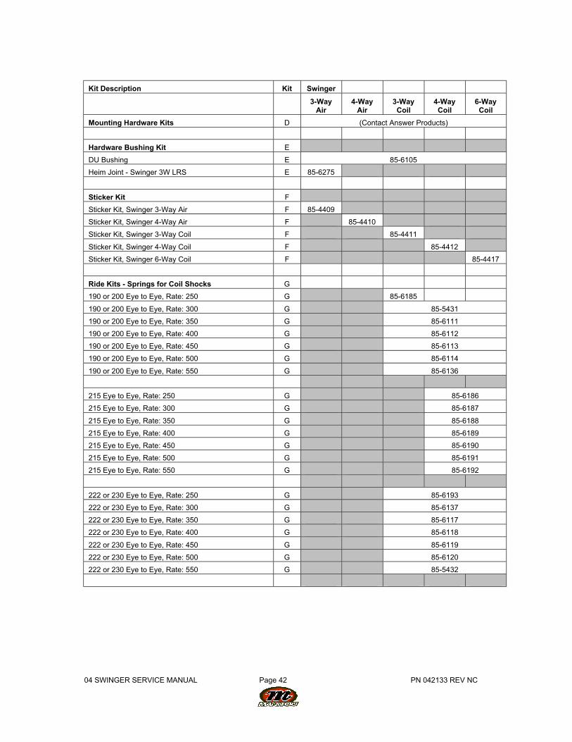
Kit Description Kit Swinger
3-Way
Air4-Way
Air3-WayCoil
4-WayCoil
6-WayCoil
Mounting Hardware Kits D (Contact Answer Products)
Hardware Bushing Kit E
DU Bushing E 85-6105
Heim Joint - Swinger 3W LRS E 85-6275
Sticker Kit F
Sticker Kit, Swinger 3-Way Air F 85-4409
Sticker Kit, Swinger 4-Way Air F 85-4410
Sticker Kit, Swinger 3-Way Coil F 85-4411
Sticker Kit, Swinger 4-Way Coil F 85-4412
Sticker Kit, Swinger 6-Way Coil F 85-4417
Ride Kits - Springs for Coil Shocks G
190 or 200 Eye to Eye, Rate: 250 G 85-6185
190 or 200 Eye to Eye, Rate: 300 G 85-5431
190 or 200 Eye to Eye, Rate: 350 G 85-6111
190 or 200 Eye to Eye, Rate: 400 G 85-6112
190 or 200 Eye to Eye, Rate: 450 G 85-6113
190 or 200 Eye to Eye, Rate: 500 G 85-6114
190 or 200 Eye to Eye, Rate: 550 G 85-6136
215 Eye to Eye, Rate: 250 G 85-6186
215 Eye to Eye, Rate: 300 G 85-6187
215 Eye to Eye, Rate: 350 G 85-6188
215 Eye to Eye, Rate: 400 G 85-6189
215 Eye to Eye, Rate: 450 G 85-6190
215 Eye to Eye, Rate: 500 G 85-6191
215 Eye to Eye, Rate: 550 G 85-6192
222 or 230 Eye to Eye, Rate: 250 G 85-6193
222 or 230 Eye to Eye, Rate: 300 G 85-6137
222 or 230 Eye to Eye, Rate: 350 G 85-6117
222 or 230 Eye to Eye, Rate: 400 G 85-6118
222 or 230 Eye to Eye, Rate: 450 G 85-6119
222 or 230 Eye to Eye, Rate: 500 G 85-6120
222 or 230 Eye to Eye, Rate: 550 G 85-5432
04 SWINGER SERVICE MANUAL Page 43 PN 042133 REV NC
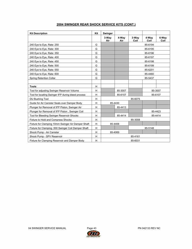
2004 SWINGER REAR SHOCK SERVICE KITS (CONT.)
Kit Description Kit Swinger
3-Way
Air4-Way
Air3-WayCoil
4-WayCoil
6-WayCoil
240 Eye to Eye, Rate: 250 G 85-6194
240 Eye to Eye, Rate: 300 G 85-6195
240 Eye to Eye, Rate: 350 G 85-6196
240 Eye to Eye, Rate: 400 G 85-6197
240 Eye to Eye, Rate: 450 G 85-6198
240 Eye to Eye, Rate: 500 G 85-6199
240 Eye to Eye, Rate: 550 G 85-6201
240 Eye to Eye, Rate: 600 G 85-4460
Spring Retention Collar G 85-5437
Tools H
Tool for adjusting Swinger Reservoir Volume H 85-3007 85-3007
Tool for locating Swinger IFP during bleed process H 85-6107 85-6107
DU Bushing Tool H 85-6075
Guide for Air Canister Seals over Damper Body H 85-4430
Plunger for Removal of IFP Piston, Swinger Air H 85-4413
Plunger for Removal of IFP Piston , Swinger Coil H 85-4423
Tool for Bleeding Swinger Reservoir Shocks H 85-4414 85-4414
Fixture to Hold and Compress Shocks H 85-3008
Fixture for Clamping 10mm Swinger Air Damper Shaft H 85-4406
Fixture for Clamping .500 Swinger Coil Damper Shaft H 85-5148
Shock Pump - Air Canister H 85-4069
Shock Pump - SPV Reservoir H 85-4161
Fixture for Clamping Reservoir and Damper Body H 85-6031
04 SWINGER SERVICE MANUAL Page 44 PN 042133 REV NC
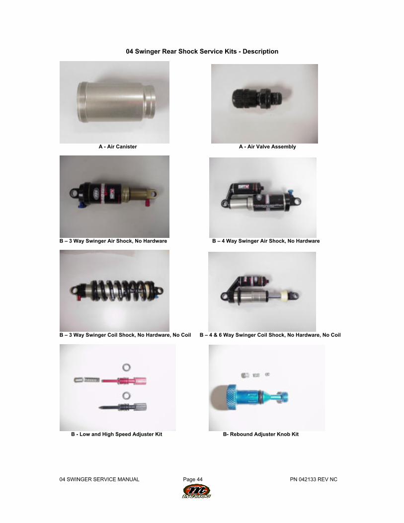
04 Swinger Rear Shock Service Kits - Description
A - Air Canister A - Air Valve Assembly
B – 3 Way Swinger Air Shock, No Hardware B – 4 Way Swinger Air Shock, No Hardware
B – 3 Way Swinger Coil Shock, No Hardware, No Coil B – 4 & 6 Way Swinger Coil Shock, No Hardware, No Coil
B - Low and High Speed Adjuster Kit B- Rebound Adjuster Knob Kit
04 SWINGER SERVICE MANUAL Page 45 PN 042133 REV NC
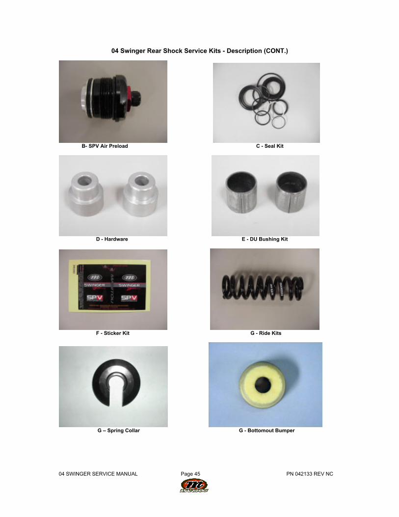
04 Swinger Rear Shock Service Kits - Description (CONT.)
B- SPV Air Preload C - Seal Kit
D - Hardware E - DU Bushing Kit
F - Sticker Kit G - Ride Kits
G – Spring Collar G - Bottomout Bumper
04 SWINGER SERVICE MANUAL Page 46 PN 042133 REV NC
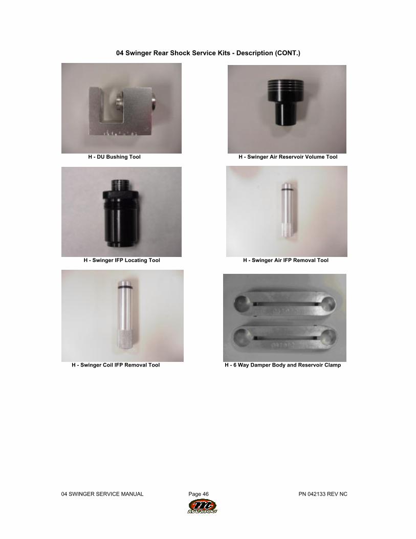
04 Swinger Rear Shock Service Kits - Description (CONT.)
H - DU Bushing Tool H - Swinger Air Reservoir Volume Tool
H - Swinger IFP Locating Tool H - Swinger Air IFP Removal Tool
H - Swinger Coil IFP Removal Tool H - 6 Way Damper Body and Reservoir Clamp
04 SWINGER SERVICE MANUAL Page 47 PN 042133 REV NC
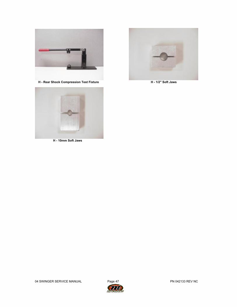
H - Rear Shock Compression Test Fixture H - 1/2" Soft Jaws
H - 10mm Soft Jaws
![INDEX [my-sport.spb.ru]my-sport.spb.ru/manual_1/1996 dh3.pdf1) The Marzocchi suspension system is designed to absorb the shocks of an uneven road surface in order to give the rider](https://img.pdfslide.us/doc/110x75/606c34f8fe454c1b506322e8/index-my-sportspbrumy-sportspbrumanual11996-dh3pdf-1-the-marzocchi-suspension.jpg)