Embed Size (px)
Citation preview
FW-2
FOREWORDFOREWORD
1. Foreword
A: FOREWORD
These manuals are used when performing mainte-nance, repair, or diagnosis of the Subaru FOREST-ER.
Applied model: SG***** from 2004MY
The manuals contain the latest information at thetime of publication. Changes in specifications,methods, etc. may be made without notice.
HU-2
HOW TO USE THIS MANUALHOW TO USE THIS MANUAL
1. How to Use This Manual
A: HOW TO USE THIS MANUAL
1. STRUCTURE
Each section consists of SCT that are broken downinto SC that are divided into sections for each com-ponent. The specification, maintenance and otherinformation for the components are included, anddiagnosis information has also been added wherenecessary.
2. INDEX
The first page has an index with tabs.
HU-3
HOW TO USE THIS MANUALHOW TO USE THIS MANUAL
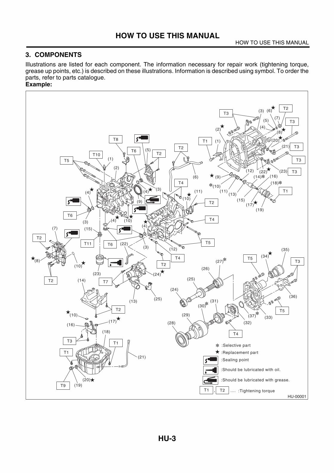
3. COMPONENTS
Illustrations are listed for each component. The information necessary for repair work (tightening torque,grease up points, etc.) is described on these illustrations. Information is described using symbol. To order theparts, refer to parts catalogue.Example:
HU-00001
(14)
(9)
(8)
(7)
(6)
(10)
(4) (10)
(22)
(11)
(19)
(17)(15)
(13)
(12)
(18)
(16)
(1)
(2)
(3)
(4)
(5)
(6)
(7)
(8)
(11)(10)
(9)
(12)
(13)
(19)
(18)
(20)
(17)(16)
(24)
(10)
(25)
(5)
(4)(4)
(4)
(3)
(3)
(3)
(2)
(1)
(21)
(15)
(23)
T7
T2
T2
T2
T2
T2
T2
T4
T5
T5
T8
T6
T6
T6T11
T10
T1
T1
T3
T3
T3
T1
T9
T4
T5
T5T3
T4
T3
T2
T4
T2
T1
T3
(20)
(21)
(23)(22)
(10)
(24)
(25)
(26)
(35)
(34)
(27)
(14)
(28)
(29)
(31)
(32)
(37)
(30)
(33)
(36)
T3
T2T1
:Selective part
:Replacement part
:Should be lubricated with grease.
:Should be lubricated with oil.
:Sealing point
:Tightening torque....,
HU-4
HOW TO USE THIS MANUALHOW TO USE THIS MANUAL
4. SPECIFICATIONS
If necessary, specifications are also included.
5. INSPECTION
Inspections are included to be carried out before and after maintenance.
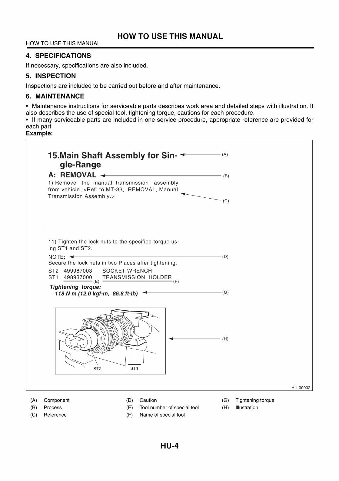
6. MAINTENANCE
• Maintenance instructions for serviceable parts describes work area and detailed steps with illustration. Italso describes the use of special tool, tightening torque, cautions for each procedure.• If many serviceable parts are included in one service procedure, appropriate reference are provided foreach part.Example:
(A) Component (D) Caution (G) Tightening torque
(B) Process (E) Tool number of special tool (H) Illustration
(C) Reference (F) Name of special tool
HU-00002
1) Remove the manual transmission assembly
from vehicie. <Ref. to MT-33, REMOVAL, Manual
Transmission Assembly.>
15.Main Shaft Assembly for Sin-gle-Range
A: REMOVAL
11) Tighten the lock nuts to the specified torque us-
ing ST1 and ST2.
NOTE:Secure the lock nuts in two Places affer tightening.
ST2 499987003 SOCKET WRENCH
ST1 498937000 TRANSMISSION HOLDER
(A)
(B)
(C)
(D)
(G)
(E) (F)
(H)
Tightening torque: 118 N m (12.0 kgf-m, 86.8 ft-lb)
ST1ST2
HU-5
HOW TO USE THIS MANUALHOW TO USE THIS MANUAL
7. DIAGNOSIS
Tables showing a step-by-step process make iteasy to conduct diagnosis.
8. SI UNITS
Measurements in these manuals are according tothe SI units. Metric and yard/pound measurementsare also included. Example:
Tightening torque:44 N·m (4.5 kgf-m, 33 ft-lb)
HU-6
HOW TO USE THIS MANUALHOW TO USE THIS MANUAL
ID-2
IDENTIFICATIONIDENTIFICATION
1. Identification
A: IDENTIFICATION
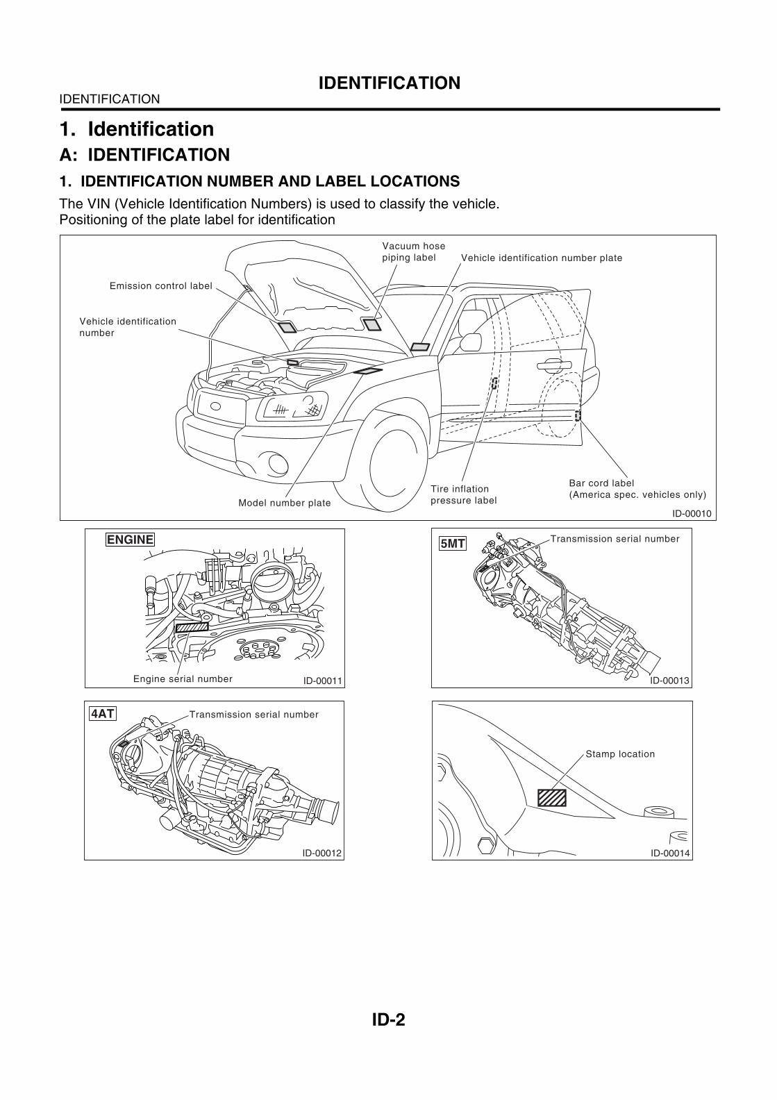
1. IDENTIFICATION NUMBER AND LABEL LOCATIONS
The VIN (Vehicle Identification Numbers) is used to classify the vehicle.Positioning of the plate label for identification
ID-00010
Bar cord label
(America spec. vehicles only)Tire inflation
pressure label
Vehicle identification number plate
Vehicle identification
number
Model number plate
Emission control label
Vacuum hose
piping label
ID-00011Engine serial number
ENGINE
ID-00012
4AT Transmission serial number
ID-00013
Transmission serial number5MT
ID-00014
Stamp location
ID-3
IDENTIFICATIONIDENTIFICATION
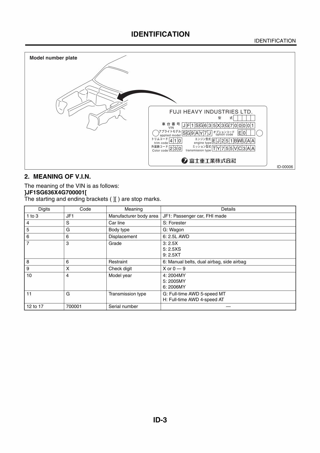
2. MEANING OF V.I.N.
The meaning of the VIN is as follows:]JF1SG636X4G700001[The starting and ending brackets ( ][ ) are stop marks.
Digits Code Meaning Details
1 to 3 JF1 Manufacturer body area JF1: Passenger car, FHI made
4 S Car line S: Forester
5 G Body type G: Wagon
6 6 Displacement 6: 2.5L AWD
7 3 Grade 3: 2.5X
5: 2.5XS
9: 2.5XT
8 6 Restraint 6: Manual belts, dual airbag, side airbag
9 X Check digit X or 0 — 9
10 4 Model year 4: 2004MY
5: 2005MY
6: 2006MY
11 G Transmission type G: Full-time AWD 5-speed MT
H: Full-time AWD 4-speed AT
12 to 17 700001 Serial number —
ID-00006
4 1
J F 1 S G 6 3
S G 9 A Y 7 J
5 X 3
E J 2 5 1 BWU A A
T Y 7 5 5 V C 3 A A
G 7 0 0 0 0
E 0
1
0
2 3 0
applied model option code
trim code
VIN
engine type
transmission typeColor code
FUJI HEAVY INDUSTRIES LTD.
Model number plate
ID-4
IDENTIFICATIONIDENTIFICATION
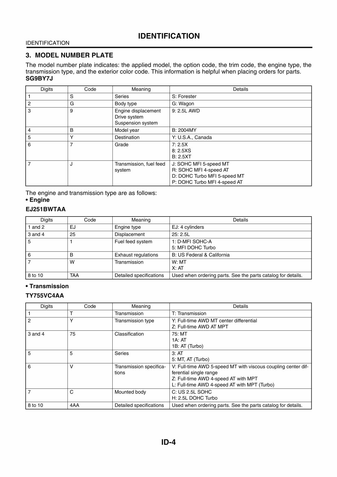
3. MODEL NUMBER PLATE
The model number plate indicates: the applied model, the option code, the trim code, the engine type, thetransmission type, and the exterior color code. This information is helpful when placing orders for parts.SG9BY7J
The engine and transmission type are as follows:• Engine
EJ251BWTAA
• Transmission
TY755VC4AA
Digits Code Meaning Details
1 S Series S: Forester
2 G Body type G: Wagon
3 9 Engine displacement
Drive system
Suspension system
9: 2.5L AWD
4 B Model year B: 2004MY
5 Y Destination Y: U.S.A., Canada
6 7 Grade 7: 2.5X
8: 2.5XS
B: 2.5XT
7 J Transmission, fuel feed
system
J: SOHC MFI 5-speed MT
R: SOHC MFI 4-speed AT
D: DOHC Turbo MFI 5-speed MT
P: DOHC Turbo MFI 4-speed AT
Digits Code Meaning Details
1 and 2 EJ Engine type EJ: 4 cylinders
3 and 4 25 Displacement 25: 2.5L
5 1 Fuel feed system 1: D-MFI SOHC-A
5: MFI DOHC Turbo
6 B Exhaust regulations B: US Federal & California
7 W Transmission W: MT
X: AT
8 to 10 TAA Detailed specifications Used when ordering parts. See the parts catalog for details.
Digits Code Meaning Details
1 T Transmission T: Transmission
2 Y Transmission type Y: Full-time AWD MT center differential
Z: Full-time AWD AT MPT
3 and 4 75 Classification 75: MT
1A: AT
1B: AT (Turbo)
5 5 Series 3: AT
5: MT, AT (Turbo)
6 V Transmission specifica-
tions
V: Full-time AWD 5-speed MT with viscous coupling center dif-
ferential single range
Z: Full-time AWD 4-speed AT with MPT
L: Full-time AWD 4-speed AT with MPT (Turbo)
7 C Mounted body C: US 2.5L SOHC
H: 2.5L DOHC Turbo
8 to 10 4AA Detailed specifications Used when ordering parts. See the parts catalog for details.
ID-5
IDENTIFICATIONIDENTIFICATION
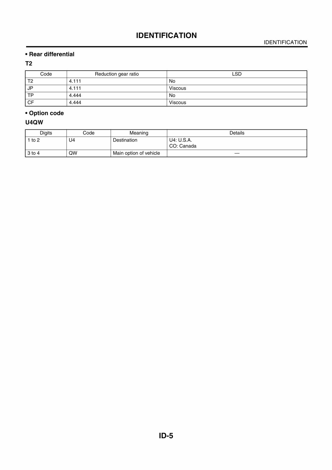
• Rear differential
T2
• Option code
U4QW
Code Reduction gear ratio LSD
T2 4.111 No
JP 4.111 Viscous
TP 4.444 No
CF 4.444 Viscous
Digits Code Meaning Details
1 to 2 U4 Destination U4: U.S.A.
CO: Canada
3 to 4 QW Main option of vehicle —
ID-6
IDENTIFICATIONIDENTIFICATION
NT-2
NOTENOTE
1. Note
A: NOTEThis is information that can improve efficiency ofmaintenance and assure sound work.
1. FASTENER NOTICE
Fasteners are used to prevent parts from damageand dislocation due to looseness. Fasteners mustbe tightened to the specified torque.Do not apply paint, lubricant, rust retardant, or oth-er substances to the surface around bolts, fasten-ers, etc. Doing so will make it difficult to obtain thecorrect torque and result in looseness and otherproblems.
2. STATIC ELECTRICITY DAMAGE
Do not touch the control unit, connectors, logicboards, and other such parts when there is a risk ofstatic electricity. Always use a static electricity pre-vention cord or touch grounded metal before con-ducting work.
3. BATTERY
When removing the battery cables, always be sureto turn the ignition off to prevent electrical damageto the control unit from rush current.
4. SERVICE PARTS
Use authentic service parts for maximum perfor-mance and maintenance, when conducting repairs.Subaru/FHI will not be responsible for poor perfor-mance resulting from the use of parts not specifiedby a genuine dealer.
5. PROTECTING VEHICLE UNDER MAIN-TENANCE
Make sure to attach the fender cover, seat covers,etc. before work.
6. ENSURING SAFETY DURING WORK
When working in a group of two or more, performthe work with calling each other to ensure mutualsafety.
NT-3
NOTENOTE
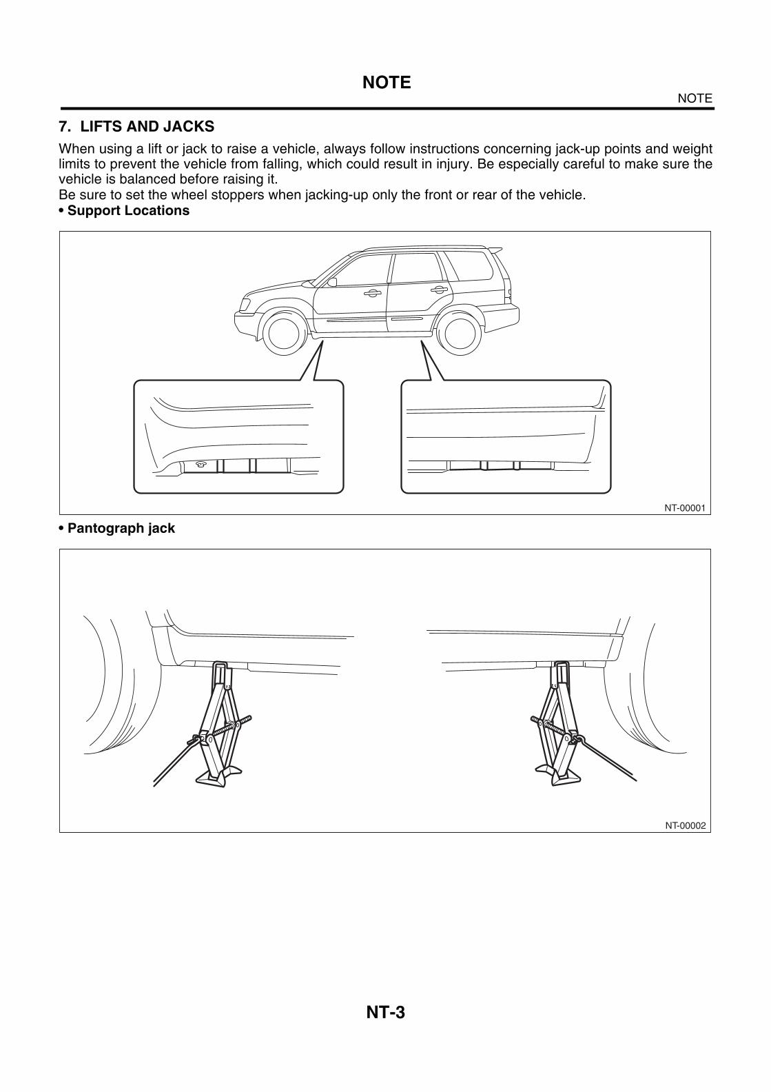
7. LIFTS AND JACKS
When using a lift or jack to raise a vehicle, always follow instructions concerning jack-up points and weightlimits to prevent the vehicle from falling, which could result in injury. Be especially careful to make sure thevehicle is balanced before raising it. Be sure to set the wheel stoppers when jacking-up only the front or rear of the vehicle.• Support Locations
• Pantograph jack
NT-00001
NT-00002
NT-4
NOTENOTE
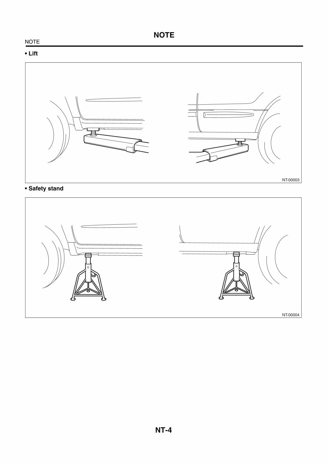
• Lift
• Safety stand
NT-00003
NT-00004
NT-5
NOTENOTE
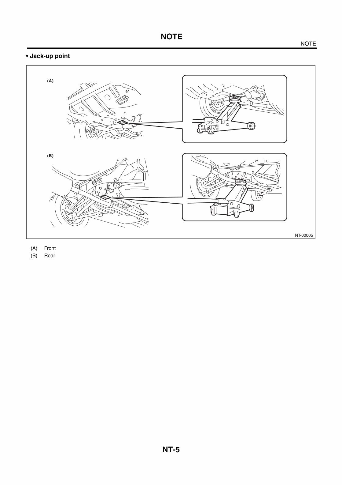
• Jack-up point
(A) Front
(B) Rear
NT-00005
(A)
(B)
NT-6
NOTENOTE
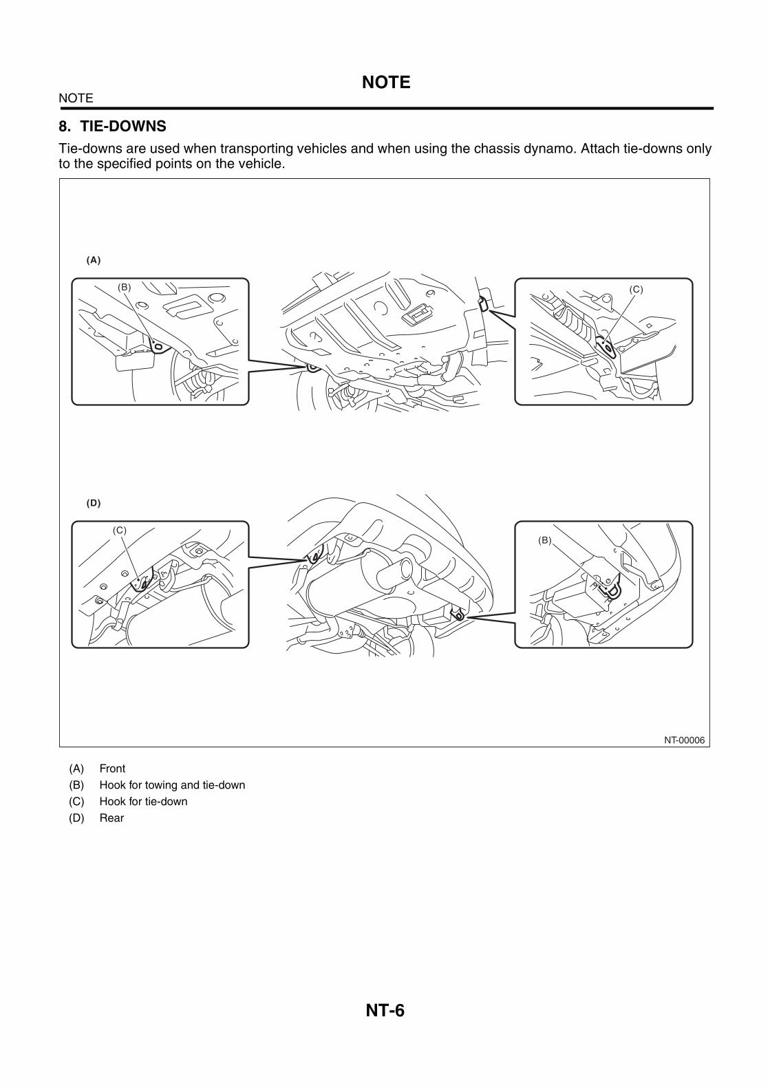
8. TIE-DOWNS
Tie-downs are used when transporting vehicles and when using the chassis dynamo. Attach tie-downs onlyto the specified points on the vehicle.
(A) Front
(B) Hook for towing and tie-down
(C) Hook for tie-down
(D) Rear
NT-00006
(B)
(C)(B)
(A)
(D)
(C)
NT-7
NOTENOTE
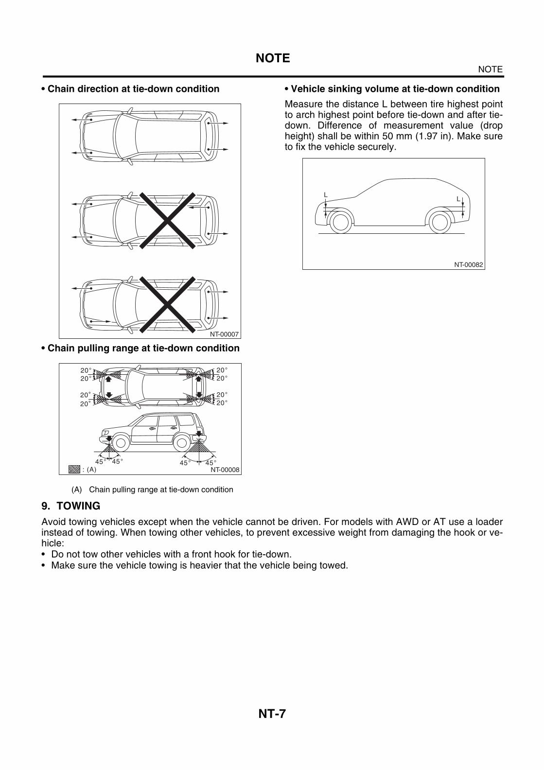
• Chain direction at tie-down condition
• Chain pulling range at tie-down condition
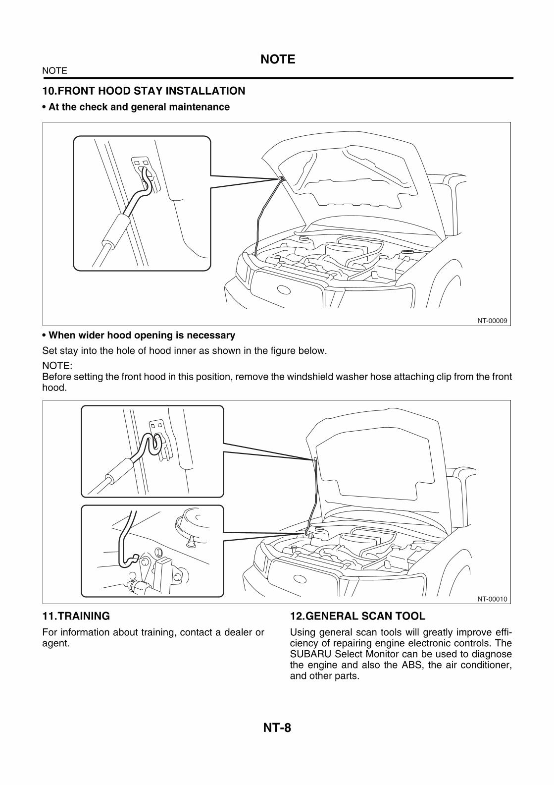
• Vehicle sinking volume at tie-down condition
Measure the distance L between tire highest pointto arch highest point before tie-down and after tie-down. Difference of measurement value (dropheight) shall be within 50 mm (1.97 in). Make sureto fix the vehicle securely.
9. TOWING
Avoid towing vehicles except when the vehicle cannot be driven. For models with AWD or AT use a loaderinstead of towing. When towing other vehicles, to prevent excessive weight from damaging the hook or ve-hicle: • Do not tow other vehicles with a front hook for tie-down.• Make sure the vehicle towing is heavier that the vehicle being towed.
(A) Chain pulling range at tie-down condition
NT-00007
NT-00008: (A)
NT-00082
LL
NT-8
NOTENOTE
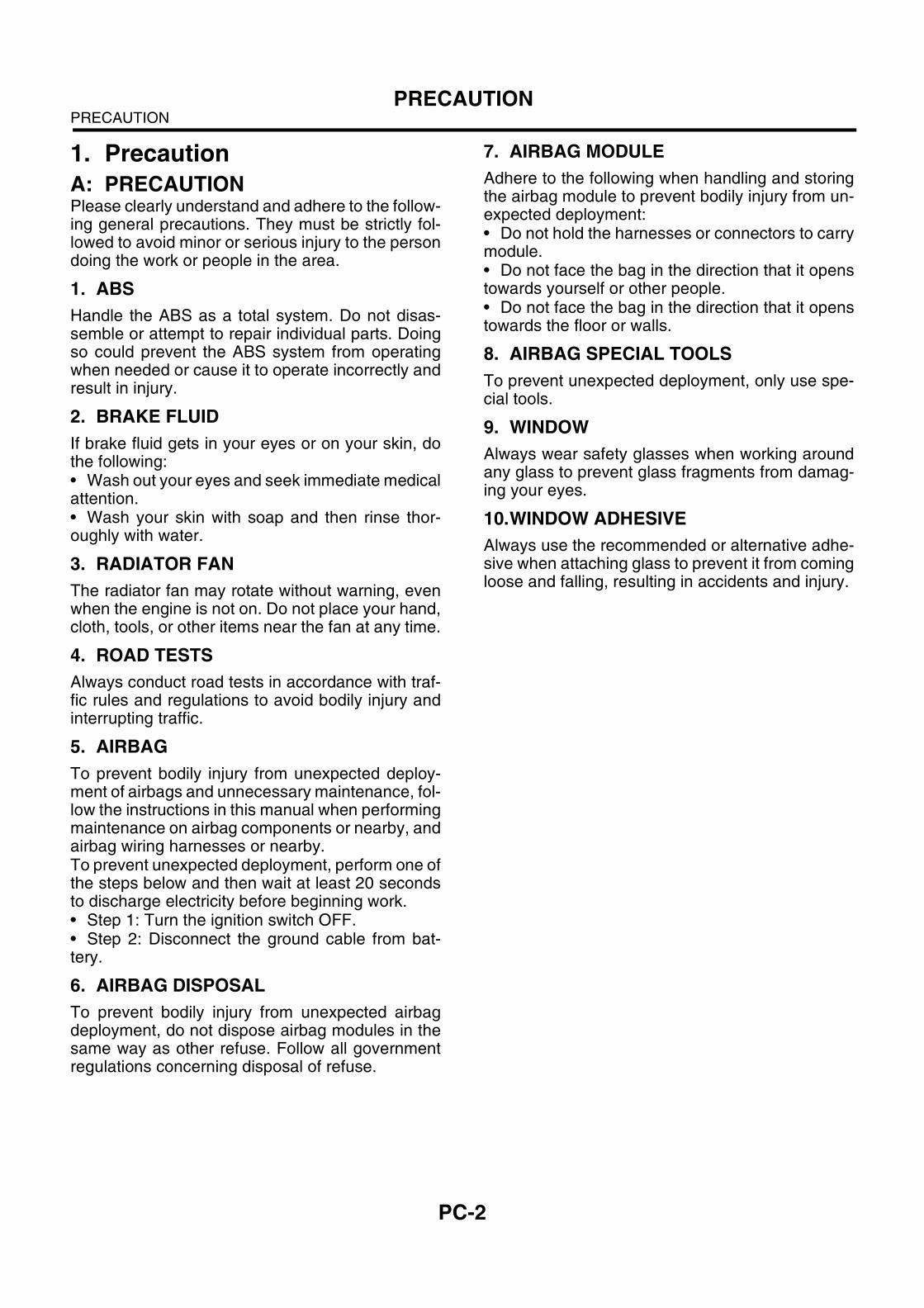
10.FRONT HOOD STAY INSTALLATION
• At the check and general maintenance
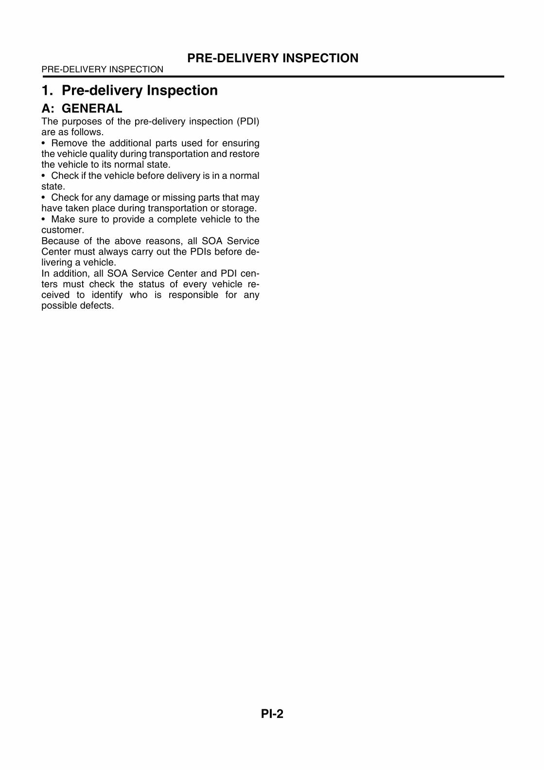
• When wider hood opening is necessary
Set stay into the hole of hood inner as shown in the figure below.
NOTE:Before setting the front hood in this position, remove the windshield washer hose attaching clip from the fronthood.
11.TRAINING
For information about training, contact a dealer oragent.
12.GENERAL SCAN TOOL
Using general scan tools will greatly improve effi-ciency of repairing engine electronic controls. TheSUBARU Select Monitor can be used to diagnosethe engine and also the ABS, the air conditioner,and other parts.
NT-00009
NT-00010
PC-2
PRECAUTIONPRECAUTION
1. Precaution
A: PRECAUTION
Please clearly understand and adhere to the follow-ing general precautions. They must be strictly fol-lowed to avoid minor or serious injury to the persondoing the work or people in the area.
1. ABS
Handle the ABS as a total system. Do not disas-semble or attempt to repair individual parts. Doingso could prevent the ABS system from operatingwhen needed or cause it to operate incorrectly andresult in injury.
2. BRAKE FLUID
If brake fluid gets in your eyes or on your skin, dothe following: • Wash out your eyes and seek immediate medicalattention.• Wash your skin with soap and then rinse thor-oughly with water.
3. RADIATOR FAN
The radiator fan may rotate without warning, evenwhen the engine is not on. Do not place your hand,cloth, tools, or other items near the fan at any time.
4. ROAD TESTS
Always conduct road tests in accordance with traf-fic rules and regulations to avoid bodily injury andinterrupting traffic.
5. AIRBAG
To prevent bodily injury from unexpected deploy-ment of airbags and unnecessary maintenance, fol-low the instructions in this manual when performingmaintenance on airbag components or nearby, andairbag wiring harnesses or nearby. To prevent unexpected deployment, perform one ofthe steps below and then wait at least 20 secondsto discharge electricity before beginning work.• Step 1: Turn the ignition switch OFF.• Step 2: Disconnect the ground cable from bat-tery.
6. AIRBAG DISPOSAL
To prevent bodily injury from unexpected airbagdeployment, do not dispose airbag modules in thesame way as other refuse. Follow all governmentregulations concerning disposal of refuse.
7. AIRBAG MODULE
Adhere to the following when handling and storingthe airbag module to prevent bodily injury from un-expected deployment: • Do not hold the harnesses or connectors to carrymodule.• Do not face the bag in the direction that it openstowards yourself or other people.• Do not face the bag in the direction that it openstowards the floor or walls.
8. AIRBAG SPECIAL TOOLS
To prevent unexpected deployment, only use spe-cial tools.
9. WINDOW
Always wear safety glasses when working aroundany glass to prevent glass fragments from damag-ing your eyes.
10.WINDOW ADHESIVE
Always use the recommended or alternative adhe-sive when attaching glass to prevent it from comingloose and falling, resulting in accidents and injury.
PI-2
PRE-DELIVERY INSPECTIONPRE-DELIVERY INSPECTION
1. Pre-delivery Inspection
A: GENERALThe purposes of the pre-delivery inspection (PDI)are as follows.• Remove the additional parts used for ensuringthe vehicle quality during transportation and restorethe vehicle to its normal state.• Check if the vehicle before delivery is in a normalstate.• Check for any damage or missing parts that mayhave taken place during transportation or storage.• Make sure to provide a complete vehicle to thecustomer.Because of the above reasons, all SOA ServiceCenter must always carry out the PDIs before de-livering a vehicle.In addition, all SOA Service Center and PDI cen-ters must check the status of every vehicle re-ceived to identify who is responsible for anypossible defects.
PI-3
PRE-DELIVERY INSPECTIONPRE-DELIVERY INSPECTION
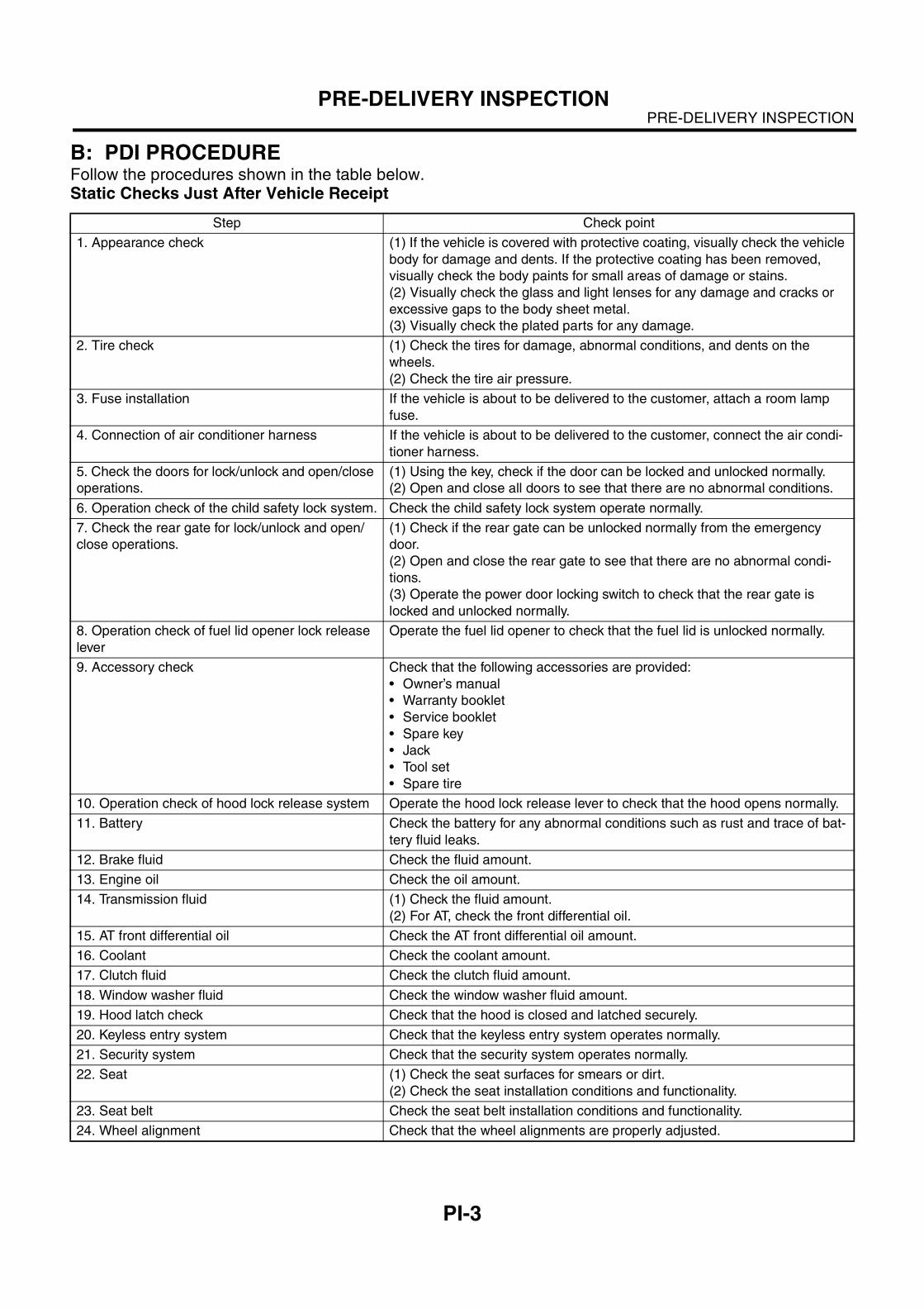
B: PDI PROCEDUREFollow the procedures shown in the table below.Static Checks Just After Vehicle Receipt
Step Check point
1. Appearance check (1) If the vehicle is covered with protective coating, visually check the vehicle
body for damage and dents. If the protective coating has been removed,
visually check the body paints for small areas of damage or stains.
(2) Visually check the glass and light lenses for any damage and cracks or
excessive gaps to the body sheet metal.
(3) Visually check the plated parts for any damage.
2. Tire check (1) Check the tires for damage, abnormal conditions, and dents on the
wheels.
(2) Check the tire air pressure.
3. Fuse installation If the vehicle is about to be delivered to the customer, attach a room lamp
fuse.
4. Connection of air conditioner harness If the vehicle is about to be delivered to the customer, connect the air condi-
tioner harness.
5. Check the doors for lock/unlock and open/close
operations.
(1) Using the key, check if the door can be locked and unlocked normally.
(2) Open and close all doors to see that there are no abnormal conditions.
6. Operation check of the child safety lock system. Check the child safety lock system operate normally.
7. Check the rear gate for lock/unlock and open/
close operations.
(1) Check if the rear gate can be unlocked normally from the emergency
door.
(2) Open and close the rear gate to see that there are no abnormal condi-
tions.
(3) Operate the power door locking switch to check that the rear gate is
locked and unlocked normally.
8. Operation check of fuel lid opener lock release
lever
Operate the fuel lid opener to check that the fuel lid is unlocked normally.
9. Accessory check Check that the following accessories are provided:
• Owner’s manual
• Warranty booklet
• Service booklet
• Spare key
• Jack
• Tool set
• Spare tire
10. Operation check of hood lock release system Operate the hood lock release lever to check that the hood opens normally.
11. Battery Check the battery for any abnormal conditions such as rust and trace of bat-
tery fluid leaks.
12. Brake fluid Check the fluid amount.
13. Engine oil Check the oil amount.
14. Transmission fluid (1) Check the fluid amount.
(2) For AT, check the front differential oil.
15. AT front differential oil Check the AT front differential oil amount.
16. Coolant Check the coolant amount.
17. Clutch fluid Check the clutch fluid amount.
18. Window washer fluid Check the window washer fluid amount.
19. Hood latch check Check that the hood is closed and latched securely.
20. Keyless entry system Check that the keyless entry system operates normally.
21. Security system Check that the security system operates normally.
22. Seat (1) Check the seat surfaces for smears or dirt.
(2) Check the seat installation conditions and functionality.
23. Seat belt Check the seat belt installation conditions and functionality.
24. Wheel alignment Check that the wheel alignments are properly adjusted.
PI-4
PRE-DELIVERY INSPECTIONPRE-DELIVERY INSPECTION
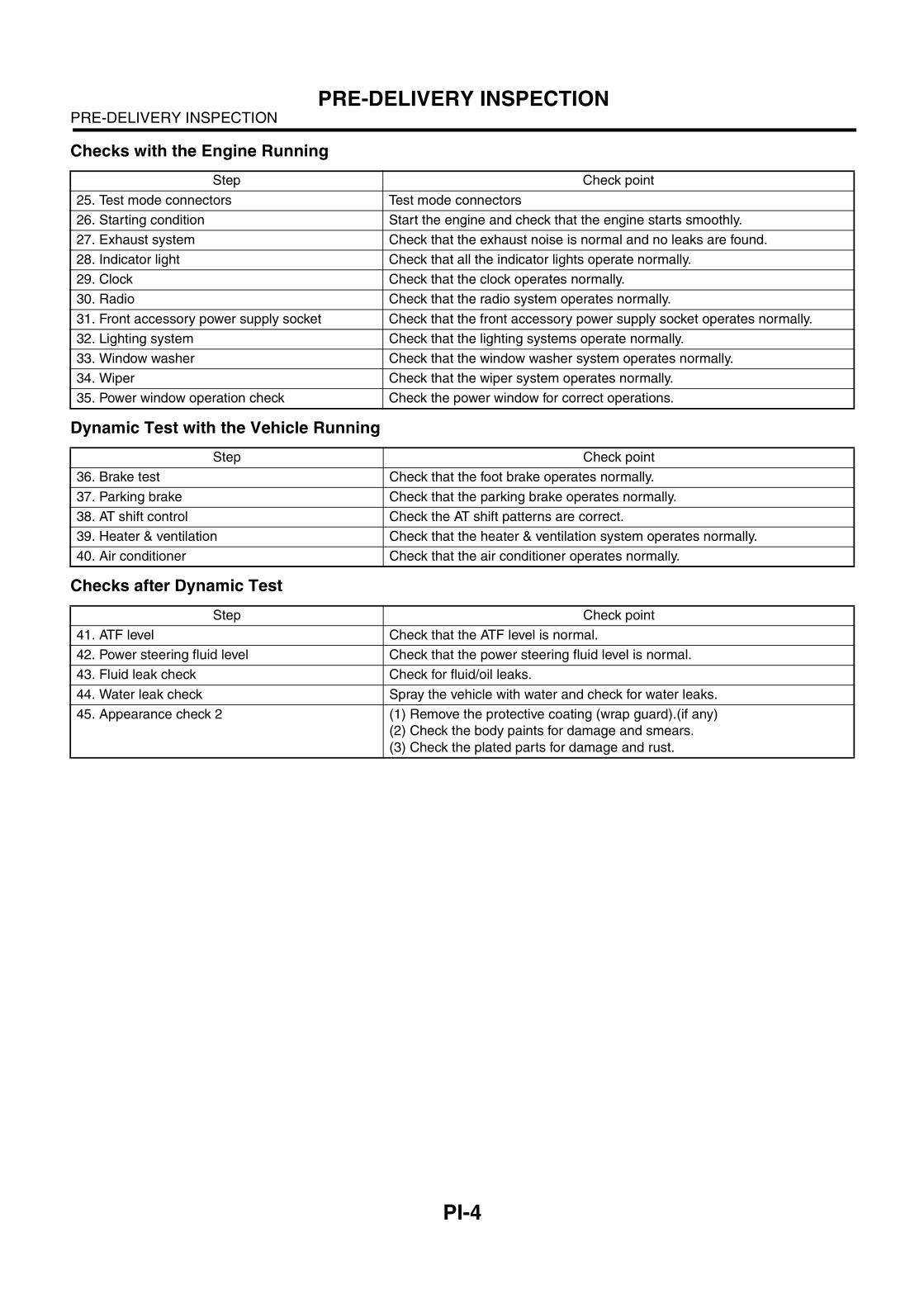
Checks with the Engine Running
Dynamic Test with the Vehicle Running
Checks after Dynamic Test
Step Check point
25. Test mode connectors Test mode connectors
26. Starting condition Start the engine and check that the engine starts smoothly.
27. Exhaust system Check that the exhaust noise is normal and no leaks are found.
28. Indicator light Check that all the indicator lights operate normally.
29. Clock Check that the clock operates normally.
30. Radio Check that the radio system operates normally.
31. Front accessory power supply socket Check that the front accessory power supply socket operates normally.
32. Lighting system Check that the lighting systems operate normally.
33. Window washer Check that the window washer system operates normally.
34. Wiper Check that the wiper system operates normally.
35. Power window operation check Check the power window for correct operations.
Step Check point
36. Brake test Check that the foot brake operates normally.
37. Parking brake Check that the parking brake operates normally.
38. AT shift control Check the AT shift patterns are correct.
39. Heater & ventilation Check that the heater & ventilation system operates normally.
40. Air conditioner Check that the air conditioner operates normally.
Step Check point
41. ATF level Check that the ATF level is normal.
42. Power steering fluid level Check that the power steering fluid level is normal.
43. Fluid leak check Check for fluid/oil leaks.
44. Water leak check Spray the vehicle with water and check for water leaks.
45. Appearance check 2 (1) Remove the protective coating (wrap guard).(if any)
(2) Check the body paints for damage and smears.
(3) Check the plated parts for damage and rust.
PI-5
PRE-DELIVERY INSPECTIONPRE-DELIVERY INSPECTION
1. APPEARANCE CHECK
1) If the vehicle is covered with protective coating,visually check the vehicle body for damage anddents.2) If there is no protective coating, check the bodypaints for small areas of damage or stains and re-pair as necessary.3) Check the window glass, door glass, and lightsfor any cracks or damage and repair or replace theparts as necessary.4) Check the plated parts, such as the grilles anddoor knobs, for damage or loss of gloss and repairor replace the parts as necessary.
2. TIRE CHECK
• Check the tire outer faces for any damage.• Check the tire air pressure by referring to the fol-lowing table.
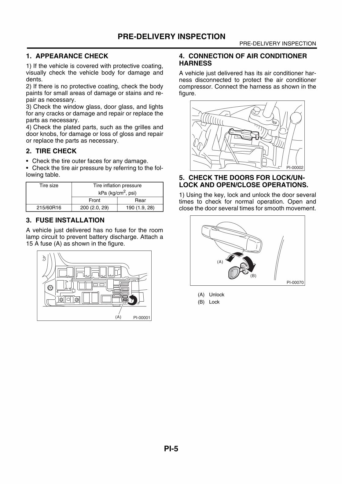
3. FUSE INSTALLATION
A vehicle just delivered has no fuse for the roomlamp circuit to prevent battery discharge. Attach a15 A fuse (A) as shown in the figure.
4. CONNECTION OF AIR CONDITIONER HARNESS
A vehicle just delivered has its air conditioner har-ness disconnected to protect the air conditionercompressor. Connect the harness as shown in thefigure.
5. CHECK THE DOORS FOR LOCK/UN-LOCK AND OPEN/CLOSE OPERATIONS.
1) Using the key, lock and unlock the door severaltimes to check for normal operation. Open andclose the door several times for smooth movement.
Tire size Tire inflation pressure
kPa (kg/cm2, psi)
Front Rear
215/60R16 200 (2.0, 29) 190 (1.9, 28)
PI-00001(A)
(A) Unlock
(B) Lock
PI-00002
PI-00070
(A)
(B)
PI-6
PRE-DELIVERY INSPECTIONPRE-DELIVERY INSPECTION
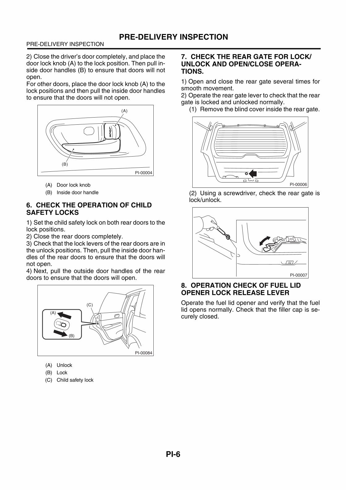
2) Close the driver’s door completely, and place thedoor lock knob (A) to the lock position. Then pull in-side door handles (B) to ensure that doors will notopen.For other doors, place the door lock knob (A) to thelock positions and then pull the inside door handlesto ensure that the doors will not open.
6. CHECK THE OPERATION OF CHILD SAFETY LOCKS
1) Set the child safety lock on both rear doors to thelock positions.2) Close the rear doors completely.3) Check that the lock levers of the rear doors are inthe unlock positions. Then, pull the inside door han-dles of the rear doors to ensure that the doors willnot open.4) Next, pull the outside door handles of the reardoors to ensure that the doors will open.
7. CHECK THE REAR GATE FOR LOCK/UNLOCK AND OPEN/CLOSE OPERA-TIONS.
1) Open and close the rear gate several times forsmooth movement. 2) Operate the rear gate lever to check that the reargate is locked and unlocked normally.
(1) Remove the blind cover inside the rear gate.
(2) Using a screwdriver, check the rear gate islock/unlock.
8. OPERATION CHECK OF FUEL LID OPENER LOCK RELEASE LEVER
Operate the fuel lid opener and verify that the fuellid opens normally. Check that the filler cap is se-curely closed.
(A) Door lock knob
(B) Inside door handle
(A) Unlock
(B) Lock
(C) Child safety lock
PI-00004
(A)
(B)
PI-00084
(A)
(B)
(C)
PI-00006
PI-00007
PI-7
PRE-DELIVERY INSPECTIONPRE-DELIVERY INSPECTION
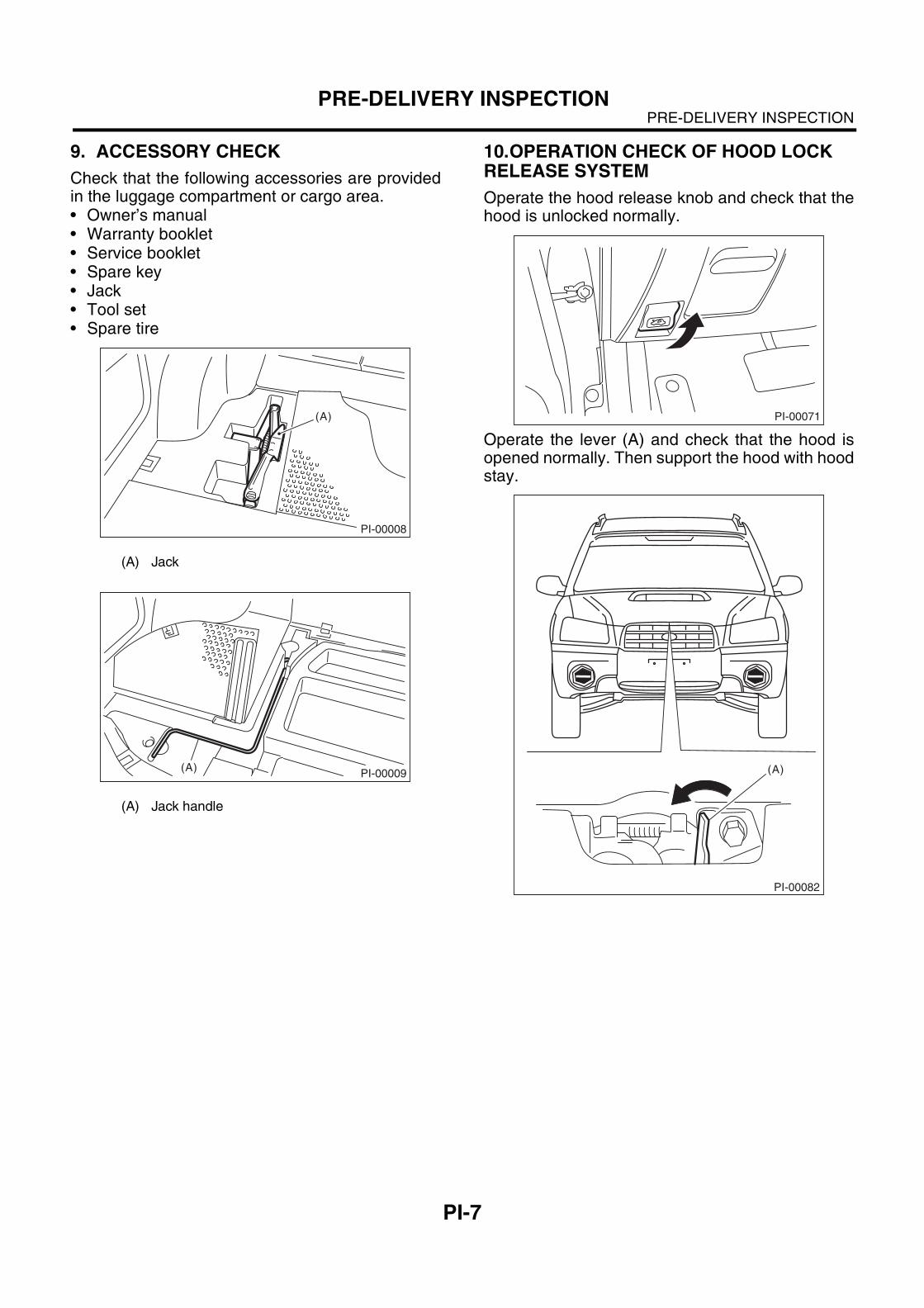
9. ACCESSORY CHECK
Check that the following accessories are providedin the luggage compartment or cargo area. • Owner’s manual• Warranty booklet• Service booklet• Spare key• Jack• Tool set• Spare tire
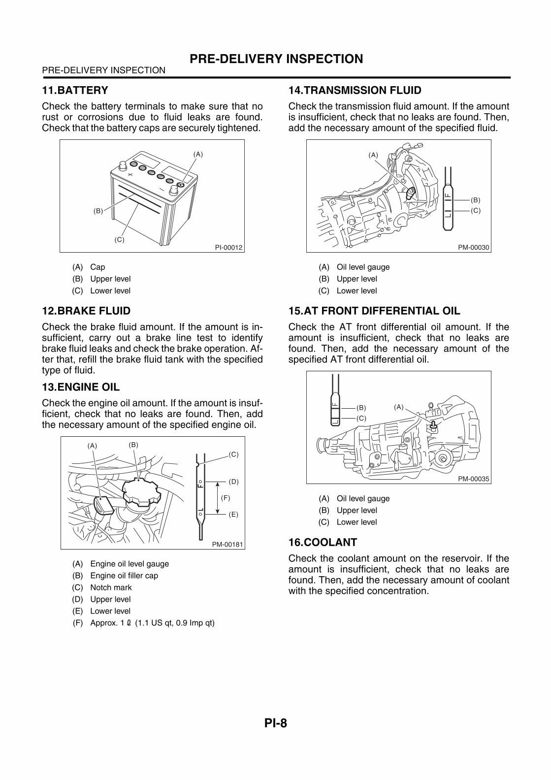
10.OPERATION CHECK OF HOOD LOCK RELEASE SYSTEM
Operate the hood release knob and check that thehood is unlocked normally.
Operate the lever (A) and check that the hood isopened normally. Then support the hood with hoodstay.
(A) Jack
(A) Jack handle
PI-00008
(A)
PI-00009(A)
PI-00071
PI-00082
(A)
PI-8
PRE-DELIVERY INSPECTIONPRE-DELIVERY INSPECTION
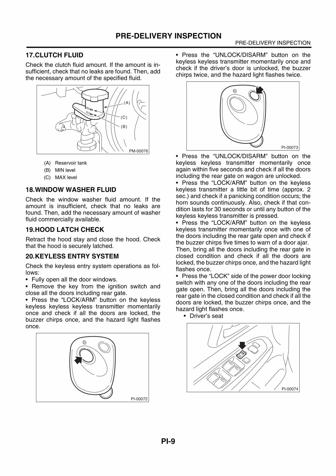
11.BATTERY
Check the battery terminals to make sure that norust or corrosions due to fluid leaks are found.Check that the battery caps are securely tightened.
12.BRAKE FLUID
Check the brake fluid amount. If the amount is in-sufficient, carry out a brake line test to identifybrake fluid leaks and check the brake operation. Af-ter that, refill the brake fluid tank with the specifiedtype of fluid.
13.ENGINE OIL
Check the engine oil amount. If the amount is insuf-ficient, check that no leaks are found. Then, addthe necessary amount of the specified engine oil.
14.TRANSMISSION FLUID
Check the transmission fluid amount. If the amountis insufficient, check that no leaks are found. Then,add the necessary amount of the specified fluid.
15.AT FRONT DIFFERENTIAL OIL
Check the AT front differential oil amount. If theamount is insufficient, check that no leaks arefound. Then, add the necessary amount of thespecified AT front differential oil.
16.COOLANT
Check the coolant amount on the reservoir. If theamount is insufficient, check that no leaks arefound. Then, add the necessary amount of coolantwith the specified concentration.
(A) Cap
(B) Upper level
(C) Lower level
(A) Engine oil level gauge
(B) Engine oil filler cap
(C) Notch mark
(D) Upper level
(E) Lower level
(F) Approx. 12 (1.1 US qt, 0.9 Imp qt)
PI-00012
(A)
(B)
(C)
PM-00181
(A) (B)
(D)
(E)
(F)
(C)
(A) Oil level gauge
(B) Upper level
(C) Lower level
(A) Oil level gauge
(B) Upper level
(C) Lower level
PM-00030
(B)
(C)
(A)
PM-00035
(B)
(C)
(A)
PI-9
PRE-DELIVERY INSPECTIONPRE-DELIVERY INSPECTION
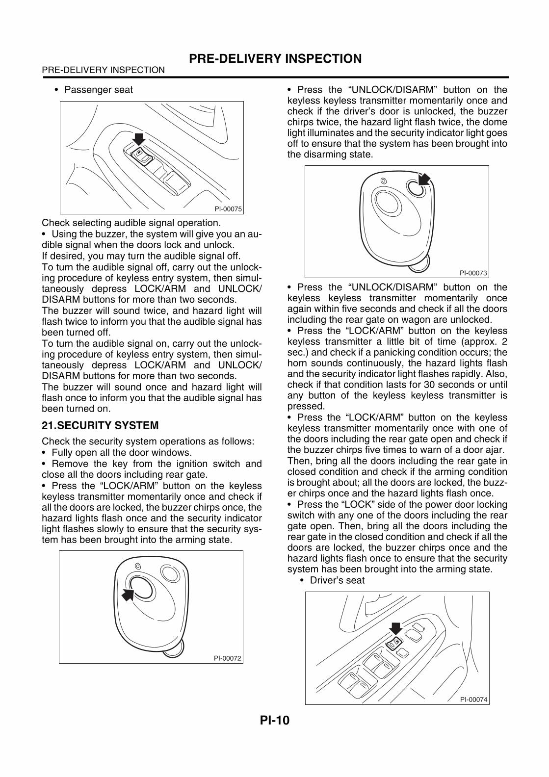
17.CLUTCH FLUID
Check the clutch fluid amount. If the amount is in-sufficient, check that no leaks are found. Then, addthe necessary amount of the specified fluid.
18.WINDOW WASHER FLUID
Check the window washer fluid amount. If theamount is insufficient, check that no leaks arefound. Then, add the necessary amount of washerfluid commercially available.
19.HOOD LATCH CHECK
Retract the hood stay and close the hood. Checkthat the hood is securely latched.
20.KEYLESS ENTRY SYSTEM
Check the keyless entry system operations as fol-lows:• Fully open all the door windows.• Remove the key from the ignition switch andclose all the doors including rear gate.• Press the “LOCK/ARM” button on the keylesskeyless keyless keyless transmitter momentarilyonce and check if all the doors are locked, thebuzzer chirps once, and the hazard light flashesonce.
• Press the “UNLOCK/DISARM” button on thekeyless keyless transmitter momentarily once andcheck if the driver’s door is unlocked, the buzzerchirps twice, and the hazard light flashes twice.
• Press the “UNLOCK/DISARM” button on thekeyless keyless transmitter momentarily onceagain within five seconds and check if all the doorsincluding the rear gate on wagon are unlocked.• Press the “LOCK/ARM” button on the keylesskeyless transmitter a little bit of time (approx. 2sec.) and check if a panicking condition occurs; thehorn sounds continuously. Also, check if that con-dition lasts for 30 seconds or until any button of thekeyless keyless transmitter is pressed.• Press the “LOCK/ARM” button on the keylesskeyless transmitter momentarily once with one ofthe doors including the rear gate open and check ifthe buzzer chirps five times to warn of a door ajar. Then, bring all the doors including the rear gate inclosed condition and check if all the doors arelocked, the buzzer chirps once, and the hazard lightflashes once.• Press the “LOCK” side of the power door lockingswitch with any one of the doors including the reargate open. Then, bring all the doors including therear gate in the closed condition and check if all thedoors are locked, the buzzer chirps once, and thehazard light flashes once.
• Driver’s seat
(A) Reservoir tank
(B) MIN level
(C) MAX level
PM-00076
(A)
(B)
(C)
PI-00072
PI-00073
PI-00074
PI-10
PRE-DELIVERY INSPECTIONPRE-DELIVERY INSPECTION
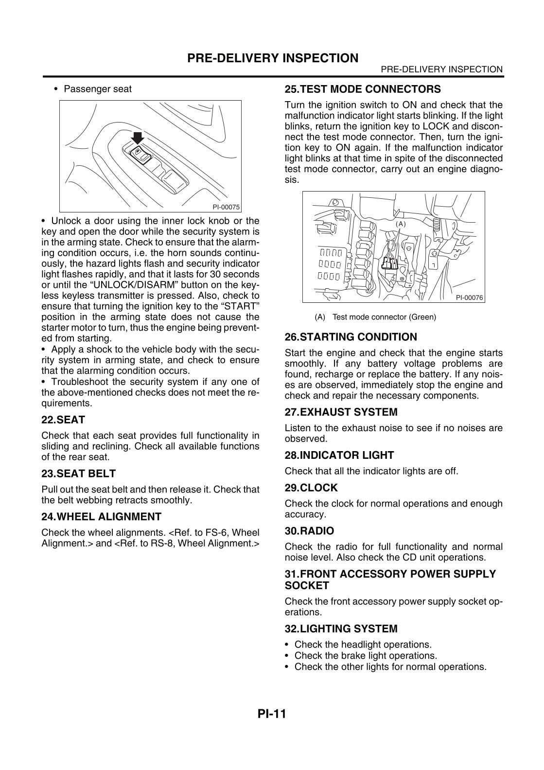
• Passenger seat
Check selecting audible signal operation.• Using the buzzer, the system will give you an au-dible signal when the doors lock and unlock.If desired, you may turn the audible signal off.To turn the audible signal off, carry out the unlock-ing procedure of keyless entry system, then simul-taneously depress LOCK/ARM and UNLOCK/DISARM buttons for more than two seconds.The buzzer will sound twice, and hazard light willflash twice to inform you that the audible signal hasbeen turned off.To turn the audible signal on, carry out the unlock-ing procedure of keyless entry system, then simul-taneously depress LOCK/ARM and UNLOCK/DISARM buttons for more than two seconds.The buzzer will sound once and hazard light willflash once to inform you that the audible signal hasbeen turned on.
21.SECURITY SYSTEM
Check the security system operations as follows:• Fully open all the door windows.• Remove the key from the ignition switch andclose all the doors including rear gate.• Press the “LOCK/ARM” button on the keylesskeyless transmitter momentarily once and check ifall the doors are locked, the buzzer chirps once, thehazard lights flash once and the security indicatorlight flashes slowly to ensure that the security sys-tem has been brought into the arming state.
• Press the “UNLOCK/DISARM” button on thekeyless keyless transmitter momentarily once andcheck if the driver’s door is unlocked, the buzzerchirps twice, the hazard light flash twice, the domelight illuminates and the security indicator light goesoff to ensure that the system has been brought intothe disarming state.
• Press the “UNLOCK/DISARM” button on thekeyless keyless transmitter momentarily onceagain within five seconds and check if all the doorsincluding the rear gate on wagon are unlocked.• Press the “LOCK/ARM” button on the keylesskeyless transmitter a little bit of time (approx. 2sec.) and check if a panicking condition occurs; thehorn sounds continuously, the hazard lights flashand the security indicator light flashes rapidly. Also,check if that condition lasts for 30 seconds or untilany button of the keyless keyless transmitter ispressed.• Press the “LOCK/ARM” button on the keylesskeyless transmitter momentarily once with one ofthe doors including the rear gate open and check ifthe buzzer chirps five times to warn of a door ajar. Then, bring all the doors including the rear gate inclosed condition and check if the arming conditionis brought about; all the doors are locked, the buzz-er chirps once and the hazard lights flash once.• Press the “LOCK” side of the power door lockingswitch with any one of the doors including the reargate open. Then, bring all the doors including therear gate in the closed condition and check if all thedoors are locked, the buzzer chirps once and thehazard lights flash once to ensure that the securitysystem has been brought into the arming state.
• Driver’s seat
PI-00075
PI-00072
PI-00073
PI-00074
PI-11
PRE-DELIVERY INSPECTIONPRE-DELIVERY INSPECTION
• Passenger seat
• Unlock a door using the inner lock knob or thekey and open the door while the security system isin the arming state. Check to ensure that the alarm-ing condition occurs, i.e. the horn sounds continu-ously, the hazard lights flash and security indicatorlight flashes rapidly, and that it lasts for 30 secondsor until the “UNLOCK/DISARM” button on the key-less keyless transmitter is pressed. Also, check toensure that turning the ignition key to the “START”position in the arming state does not cause thestarter motor to turn, thus the engine being prevent-ed from starting.• Apply a shock to the vehicle body with the secu-rity system in arming state, and check to ensurethat the alarming condition occurs.• Troubleshoot the security system if any one ofthe above-mentioned checks does not meet the re-quirements.
22.SEAT
Check that each seat provides full functionality insliding and reclining. Check all available functionsof the rear seat.
23.SEAT BELT
Pull out the seat belt and then release it. Check thatthe belt webbing retracts smoothly.
24.WHEEL ALIGNMENT
Check the wheel alignments. <Ref. to FS-6, WheelAlignment.> and <Ref. to RS-8, Wheel Alignment.>
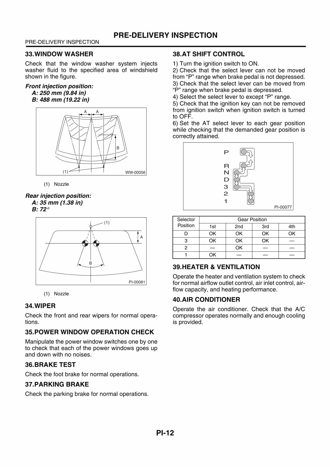
25.TEST MODE CONNECTORS
Turn the ignition switch to ON and check that themalfunction indicator light starts blinking. If the lightblinks, return the ignition key to LOCK and discon-nect the test mode connector. Then, turn the igni-tion key to ON again. If the malfunction indicatorlight blinks at that time in spite of the disconnectedtest mode connector, carry out an engine diagno-sis.
26.STARTING CONDITION
Start the engine and check that the engine startssmoothly. If any battery voltage problems arefound, recharge or replace the battery. If any nois-es are observed, immediately stop the engine andcheck and repair the necessary components.
27.EXHAUST SYSTEM
Listen to the exhaust noise to see if no noises areobserved.
28.INDICATOR LIGHT
Check that all the indicator lights are off.
29.CLOCK
Check the clock for normal operations and enoughaccuracy.
30.RADIO
Check the radio for full functionality and normalnoise level. Also check the CD unit operations.
31.FRONT ACCESSORY POWER SUPPLY SOCKET
Check the front accessory power supply socket op-erations.
32.LIGHTING SYSTEM
• Check the headlight operations.• Check the brake light operations.• Check the other lights for normal operations.
PI-00075
(A) Test mode connector (Green)
PI-00076
(A)
PI-12
PRE-DELIVERY INSPECTIONPRE-DELIVERY INSPECTION
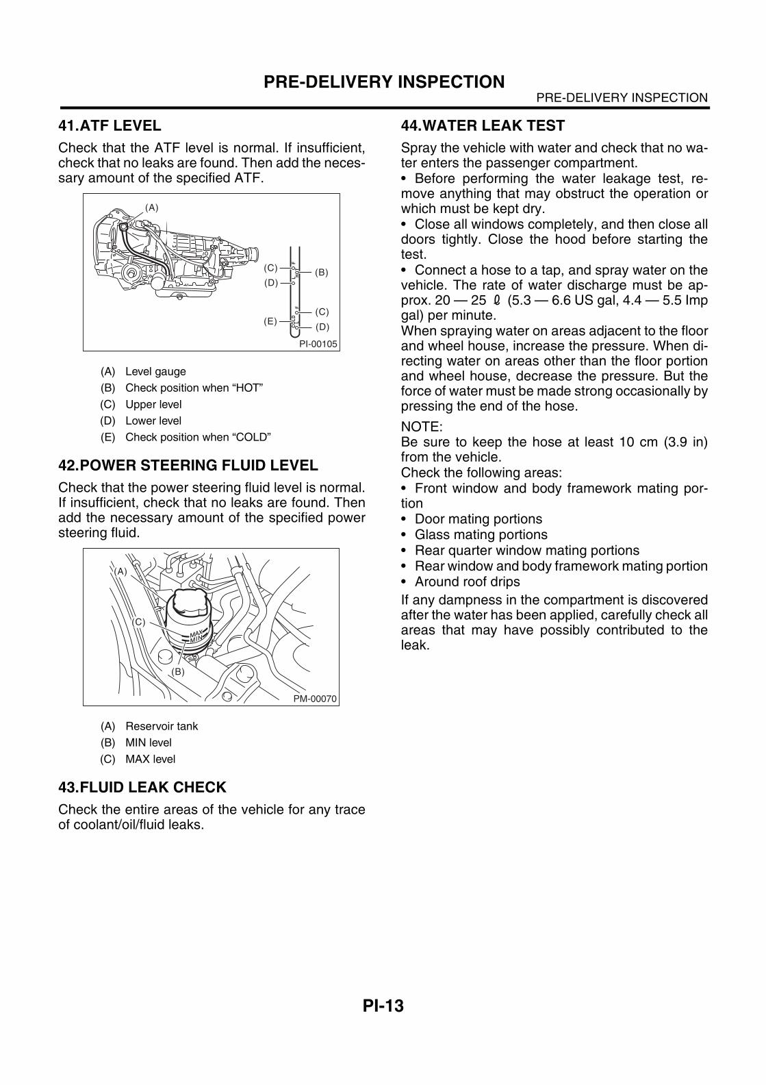
33.WINDOW WASHER
Check that the window washer system injectswasher fluid to the specified area of windshieldshown in the figure.
Front injection position:A: 250 mm (9.84 in)B: 488 mm (19.22 in)
Rear injection position:A: 35 mm (1.38 in)B: 72!
34.WIPER
Check the front and rear wipers for normal opera-tions.
35.POWER WINDOW OPERATION CHECK
Manipulate the power window switches one by oneto check that each of the power windows goes upand down with no noises.
36.BRAKE TEST
Check the foot brake for normal operations.
37.PARKING BRAKE
Check the parking brake for normal operations.
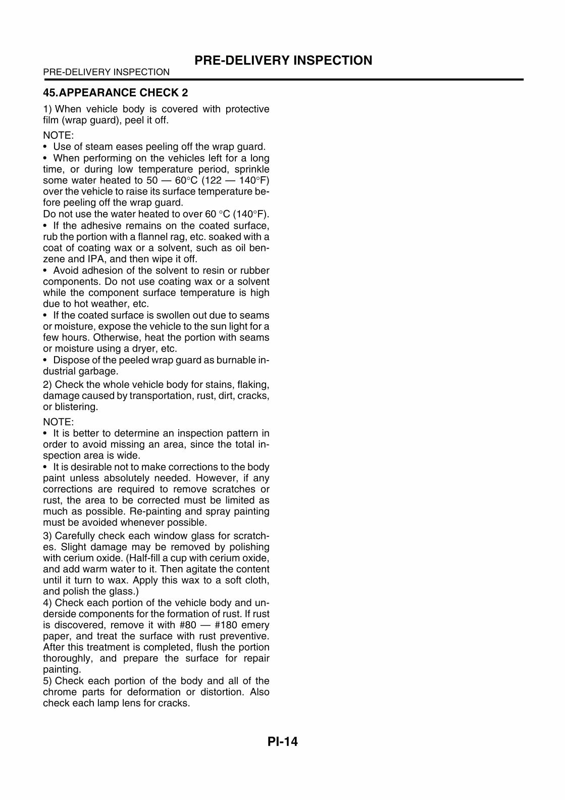
38.AT SHIFT CONTROL
1) Turn the ignition switch to ON.2) Check that the select lever can not be movedfrom “P” range when brake pedal is not depressed.3) Check that the select lever can be moved from“P” range when brake pedal is depressed.4) Select the select lever to except “P” range.5) Check that the ignition key can not be removedfrom ignition switch when ignition switch is turnedto OFF.6) Set the AT select lever to each gear positionwhile checking that the demanded gear position iscorrectly attained.
39.HEATER & VENTILATION
Operate the heater and ventilation system to checkfor normal airflow outlet control, air inlet control, air-flow capacity, and heating performance.
40.AIR CONDITIONER
Operate the air conditioner. Check that the A/Ccompressor operates normally and enough coolingis provided.
(1) Nozzle
(1) Nozzle
WW-00056(1)
A A
B
PI-00081
(1)
A
B
Selector
Position
Gear Position
1st 2nd 3rd 4th
D OK OK OK OK
3 OK OK OK —
2 — OK — —
1 OK — — —
PI-00077
P
R
N
D
3
2
1
PI-13
PRE-DELIVERY INSPECTIONPRE-DELIVERY INSPECTION
41.ATF LEVEL
Check that the ATF level is normal. If insufficient,check that no leaks are found. Then add the neces-sary amount of the specified ATF.
42.POWER STEERING FLUID LEVEL
Check that the power steering fluid level is normal.If insufficient, check that no leaks are found. Thenadd the necessary amount of the specified powersteering fluid.
43.FLUID LEAK CHECK
Check the entire areas of the vehicle for any traceof coolant/oil/fluid leaks.
44.WATER LEAK TEST
Spray the vehicle with water and check that no wa-ter enters the passenger compartment. • Before performing the water leakage test, re-move anything that may obstruct the operation orwhich must be kept dry.• Close all windows completely, and then close alldoors tightly. Close the hood before starting thetest.• Connect a hose to a tap, and spray water on thevehicle. The rate of water discharge must be ap-prox. 20 — 25 2 (5.3 — 6.6 US gal, 4.4 — 5.5 Impgal) per minute.When spraying water on areas adjacent to the floorand wheel house, increase the pressure. When di-recting water on areas other than the floor portionand wheel house, decrease the pressure. But theforce of water must be made strong occasionally bypressing the end of the hose.
NOTE:Be sure to keep the hose at least 10 cm (3.9 in)from the vehicle.Check the following areas:• Front window and body framework mating por-tion• Door mating portions• Glass mating portions• Rear quarter window mating portions• Rear window and body framework mating portion• Around roof drips
If any dampness in the compartment is discoveredafter the water has been applied, carefully check allareas that may have possibly contributed to theleak.
(A) Level gauge
(B) Check position when “HOT”
(C) Upper level
(D) Lower level
(E) Check position when “COLD”
(A) Reservoir tank
(B) MIN level
(C) MAX level
PI-00105
CO
LD
LF
HO
TL
F
(A)
(C)
(D)
(C)
(D)
(E)
(B)
PM-00070
(A)
(C)
(B)
PI-14
PRE-DELIVERY INSPECTIONPRE-DELIVERY INSPECTION
45.APPEARANCE CHECK 2
1) When vehicle body is covered with protectivefilm (wrap guard), peel it off.
NOTE:• Use of steam eases peeling off the wrap guard.• When performing on the vehicles left for a longtime, or during low temperature period, sprinklesome water heated to 50 — 60!C (122 — 140!F)over the vehicle to raise its surface temperature be-fore peeling off the wrap guard.Do not use the water heated to over 60 !C (140!F).• If the adhesive remains on the coated surface,rub the portion with a flannel rag, etc. soaked with acoat of coating wax or a solvent, such as oil ben-zene and IPA, and then wipe it off.• Avoid adhesion of the solvent to resin or rubbercomponents. Do not use coating wax or a solventwhile the component surface temperature is highdue to hot weather, etc.• If the coated surface is swollen out due to seamsor moisture, expose the vehicle to the sun light for afew hours. Otherwise, heat the portion with seamsor moisture using a dryer, etc.• Dispose of the peeled wrap guard as burnable in-dustrial garbage.
2) Check the whole vehicle body for stains, flaking,damage caused by transportation, rust, dirt, cracks,or blistering.
NOTE:• It is better to determine an inspection pattern inorder to avoid missing an area, since the total in-spection area is wide.• It is desirable not to make corrections to the bodypaint unless absolutely needed. However, if anycorrections are required to remove scratches orrust, the area to be corrected must be limited asmuch as possible. Re-painting and spray paintingmust be avoided whenever possible.
3) Carefully check each window glass for scratch-es. Slight damage may be removed by polishingwith cerium oxide. (Half-fill a cup with cerium oxide,and add warm water to it. Then agitate the contentuntil it turn to wax. Apply this wax to a soft cloth,and polish the glass.)4) Check each portion of the vehicle body and un-derside components for the formation of rust. If rustis discovered, remove it with #80 — #180 emerypaper, and treat the surface with rust preventive.After this treatment is completed, flush the portionthoroughly, and prepare the surface for repairpainting.5) Check each portion of the body and all of thechrome parts for deformation or distortion. Alsocheck each lamp lens for cracks.
RM-2
RECOMMENDED MATERIALSRECOMMENDED MATERIALS
1. Recommended Materials
A: RECOMMENDED MATERIALS
1. GENERAL
To insure the best performance, always use thespecified oil, gasoline, adhesive, sealant, etc. orthat of equivalent quality.
2. FUEL
Always use a gasoline of the same or higher octanevalue than specified in the owner’s manual. Ignor-ing the specifications below will result in damage orpoor operation of the engine and fuel injection sys-tem. Use the specified gasoline to correct perfor-mance.
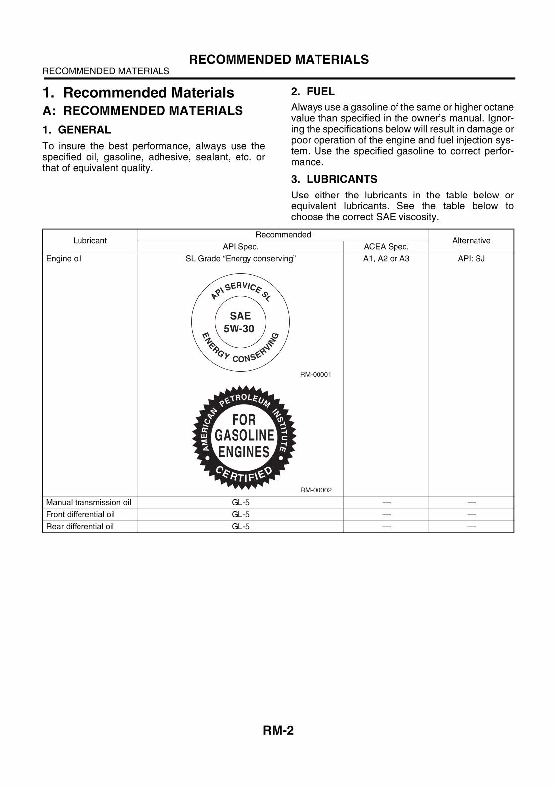
3. LUBRICANTS
Use either the lubricants in the table below orequivalent lubricants. See the table below tochoose the correct SAE viscosity.
LubricantRecommended
AlternativeAPI Spec. ACEA Spec.
Engine oil SL Grade “Energy conserving” A1, A2 or A3 API: SJ
Manual transmission oil GL-5 — —
Front differential oil GL-5 — —
Rear differential oil GL-5 — —
RM-00001
SAE5W-30
NE
ER
G
G
Y CONSERVIN
A
PI SERVICE SL
RM-00002
AM
ER
ICA
N
PETROLEUM
INS
TIT
UT
E
FORGASOLINEENGINES
CE RT I F EI D
RM-3
RECOMMENDED MATERIALSRECOMMENDED MATERIALS
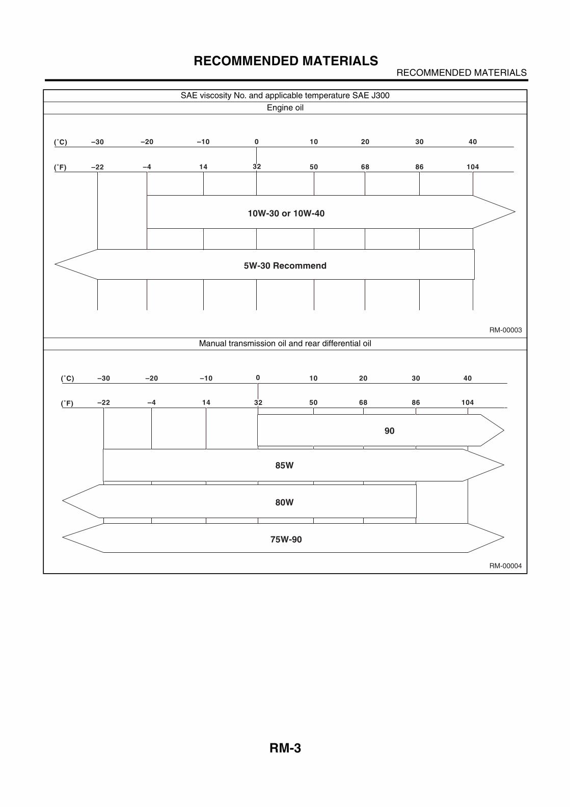
SAE viscosity No. and applicable temperature SAE J300
Engine oil
Manual transmission oil and rear differential oil
RM-00003
(˚F) –22 –4 14 50 68 86 104
(˚C) –30 –20 –10 0 10 20 30 40
5W-30 Recommend
32
10W-30 or 10W-40
RM-00004
(˚F) –22 –4 14 50 68 86 104
(˚C) –30 –20 –10 0 10 20 30 40
85W
75W-90
80W
90
32
RM-4
RECOMMENDED MATERIALSRECOMMENDED MATERIALS
4. FLUID
Use the fluids specified in the table below. Do not mix two different kinds or makes of fluid.
5. ENGINE COOLANT
Use genuine engine coolant to protect the engine.
6. REFRIGERANT
Standard air conditioners on Subaru vehicles use HFC134a refrigerant. Do not mix it with other refrigerants.Also, do not use any air compressor oil except for ZXL200PG.
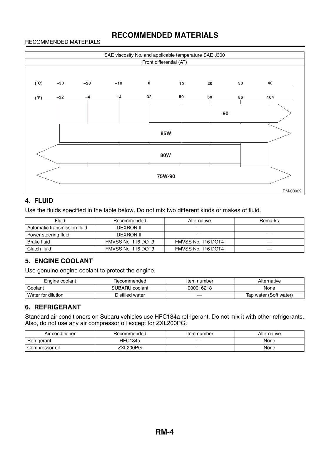
Front differential (AT)
Fluid Recommended Alternative Remarks
Automatic transmission fluid DEXRON III — —
Power steering fluid DEXRON III — —
Brake fluid FMVSS No. 116 DOT3 FMVSS No. 116 DOT4 —
Clutch fluid FMVSS No. 116 DOT3 FMVSS No. 116 DOT4 —
Engine coolant Recommended Item number Alternative
Coolant SUBARU coolant 000016218 None
Water for dilution Distilled water — Tap water (Soft water)
Air conditioner Recommended Item number Alternative
Refrigerant HFC134a — None
Compressor oil ZXL200PG — None
SAE viscosity No. and applicable temperature SAE J300
RM-00029
(˚F) –22 –4 14 50 68 86 104
(˚C) –30 –20 –10 0 10 20 30 40
32
85W
75W-90
80W
90
RM-5
RECOMMENDED MATERIALSRECOMMENDED MATERIALS
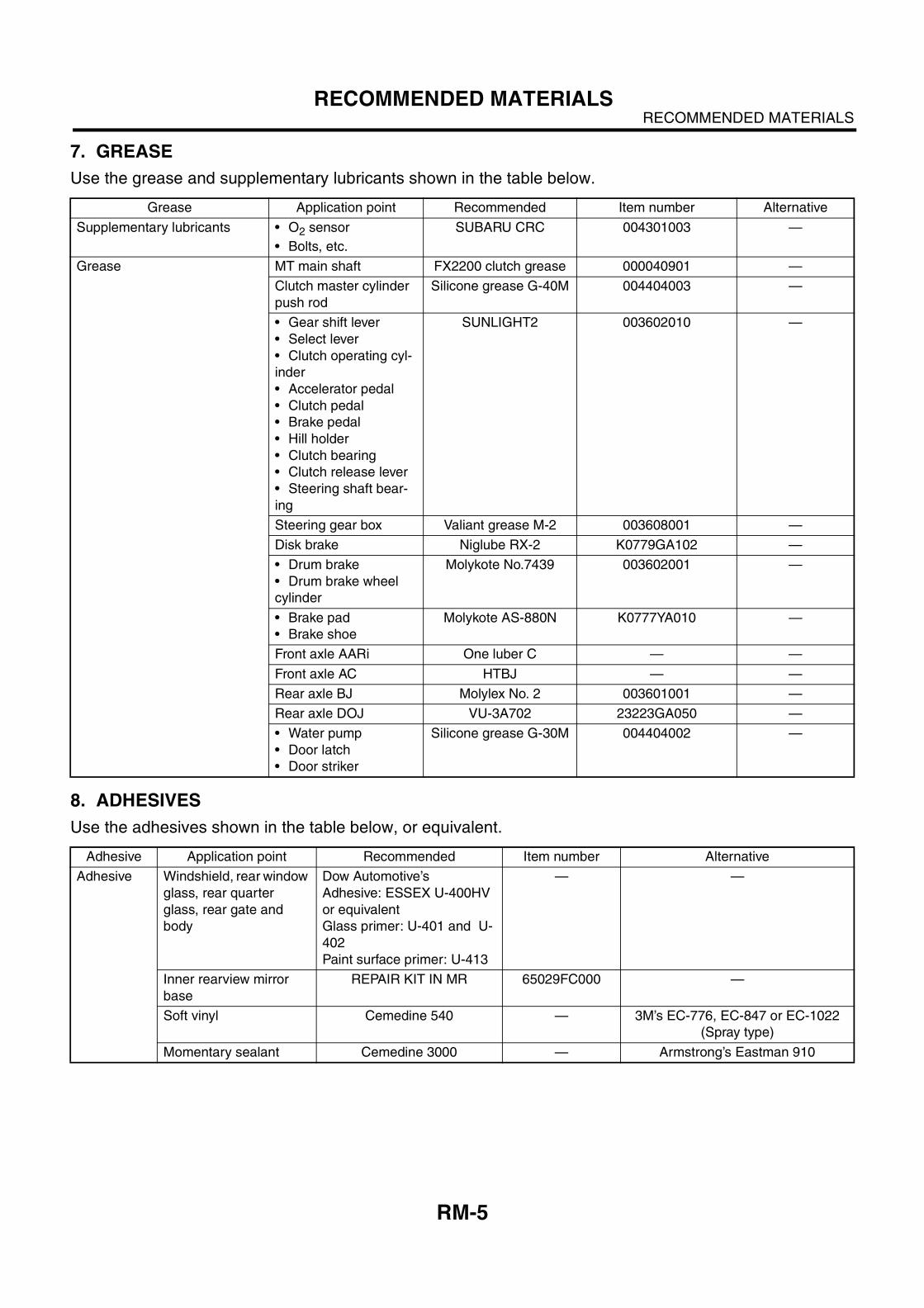
7. GREASE
Use the grease and supplementary lubricants shown in the table below.
8. ADHESIVES
Use the adhesives shown in the table below, or equivalent.
Grease Application point Recommended Item number Alternative
Supplementary lubricants • O2 sensor
• Bolts, etc.
SUBARU CRC 004301003 —
Grease MT main shaft FX2200 clutch grease 000040901 —
Clutch master cylinder
push rod
Silicone grease G-40M 004404003 —
• Gear shift lever
• Select lever
• Clutch operating cyl-
inder
• Accelerator pedal
• Clutch pedal
• Brake pedal
• Hill holder
• Clutch bearing
• Clutch release lever
• Steering shaft bear-
ing
SUNLIGHT2 003602010 —
Steering gear box Valiant grease M-2 003608001 —
Disk brake Niglube RX-2 K0779GA102 —
• Drum brake
• Drum brake wheel
cylinder
Molykote No.7439 003602001 —
• Brake pad
• Brake shoe
Molykote AS-880N K0777YA010 —
Front axle AARi One luber C — —
Front axle AC HTBJ — —
Rear axle BJ Molylex No. 2 003601001 —
Rear axle DOJ VU-3A702 23223GA050 —
• Water pump
• Door latch
• Door striker
Silicone grease G-30M 004404002 —
Adhesive Application point Recommended Item number Alternative
Adhesive Windshield, rear window
glass, rear quarter
glass, rear gate and
body
Dow Automotive’s
Adhesive: ESSEX U-400HV
or equivalent
Glass primer: U-401 and U-
402
Paint surface primer: U-413
— —
Inner rearview mirror
base
REPAIR KIT IN MR 65029FC000 —
Soft vinyl Cemedine 540 — 3M’s EC-776, EC-847 or EC-1022
(Spray type)
Momentary sealant Cemedine 3000 — Armstrong’s Eastman 910
RM-6
RECOMMENDED MATERIALSRECOMMENDED MATERIALS
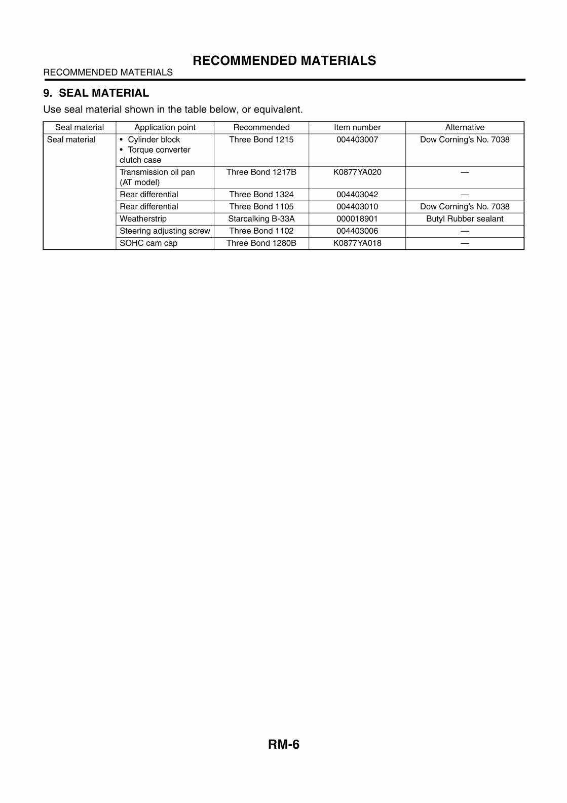
9. SEAL MATERIAL
Use seal material shown in the table below, or equivalent.
Seal material Application point Recommended Item number Alternative
Seal material • Cylinder block
• Torque converter
clutch case
Three Bond 1215 004403007 Dow Corning’s No. 7038
Transmission oil pan
(AT model)
Three Bond 1217B K0877YA020 —
Rear differential Three Bond 1324 004403042 —
Rear differential Three Bond 1105 004403010 Dow Corning’s No. 7038
Weatherstrip Starcalking B-33A 000018901 Butyl Rubber sealant
Steering adjusting screw Three Bond 1102 004403006 —
SOHC cam cap Three Bond 1280B K0877YA018 —
SPC-2
SPECIFICATIONSFORESTER
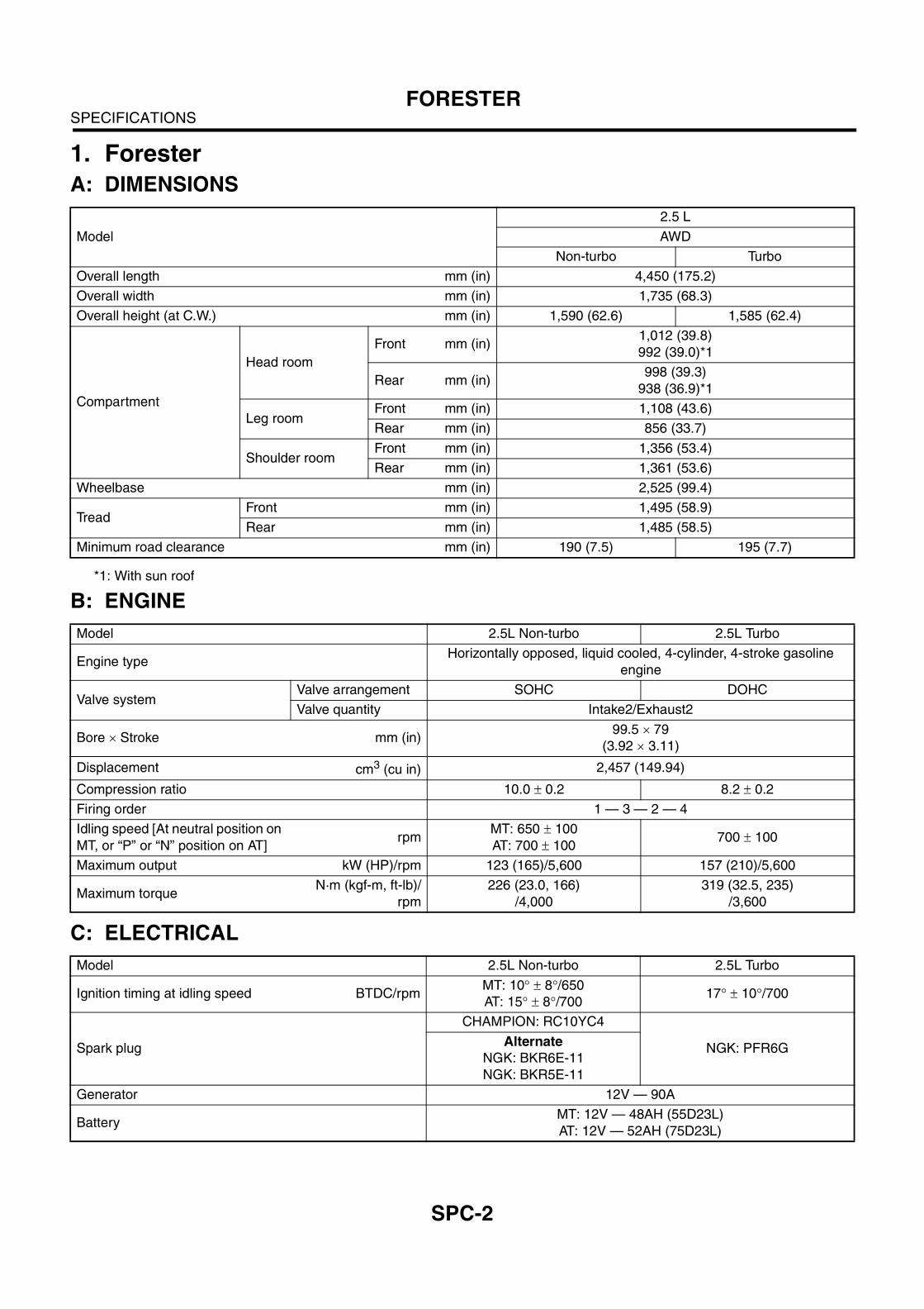
1. Forester
A: DIMENSIONS
*1: With sun roof
B: ENGINE
C: ELECTRICAL
Model
2.5 L
AWD
Non-turbo Turbo
Overall length mm (in) 4,450 (175.2)
Overall width mm (in) 1,735 (68.3)
Overall height (at C.W.) mm (in) 1,590 (62.6) 1,585 (62.4)
Compartment
Head room
Front mm (in)1,012 (39.8)
992 (39.0)*1
Rear mm (in)998 (39.3)
938 (36.9)*1
Leg roomFront mm (in) 1,108 (43.6)
Rear mm (in) 856 (33.7)
Shoulder roomFront mm (in) 1,356 (53.4)
Rear mm (in) 1,361 (53.6)
Wheelbase mm (in) 2,525 (99.4)
Tread Front mm (in) 1,495 (58.9)
Rear mm (in) 1,485 (58.5)
Minimum road clearance mm (in) 190 (7.5) 195 (7.7)
Model 2.5L Non-turbo 2.5L Turbo
Engine typeHorizontally opposed, liquid cooled, 4-cylinder, 4-stroke gasoline
engine
Valve systemValve arrangement SOHC DOHC
Valve quantity Intake2/Exhaust2
Bore ! Stroke mm (in)99.5 ! 79
(3.92 ! 3.11)
Displacement cm3 (cu in) 2,457 (149.94)
Compression ratio 10.0 " 0.2 8.2 " 0.2
Firing order 1 — 3 — 2 — 4
Idling speed [At neutral position on
MT, or “P” or “N” position on AT]rpm
MT: 650 " 100
AT: 700 " 100700 " 100
Maximum output kW (HP)/rpm 123 (165)/5,600 157 (210)/5,600
Maximum torqueN·m (kgf-m, ft-lb)/
rpm
226 (23.0, 166)
/4,000
319 (32.5, 235)
/3,600
Model 2.5L Non-turbo 2.5L Turbo
Ignition timing at idling speed BTDC/rpmMT: 10# " 8#/650
AT: 15# " 8#/70017# " 10#/700
Spark plug
CHAMPION: RC10YC4
NGK: PFR6GAlternate
NGK: BKR6E-11
NGK: BKR5E-11
Generator 12V — 90A
BatteryMT: 12V — 48AH (55D23L)
AT: 12V — 52AH (75D23L)
SPC-3
SPECIFICATIONSFORESTER
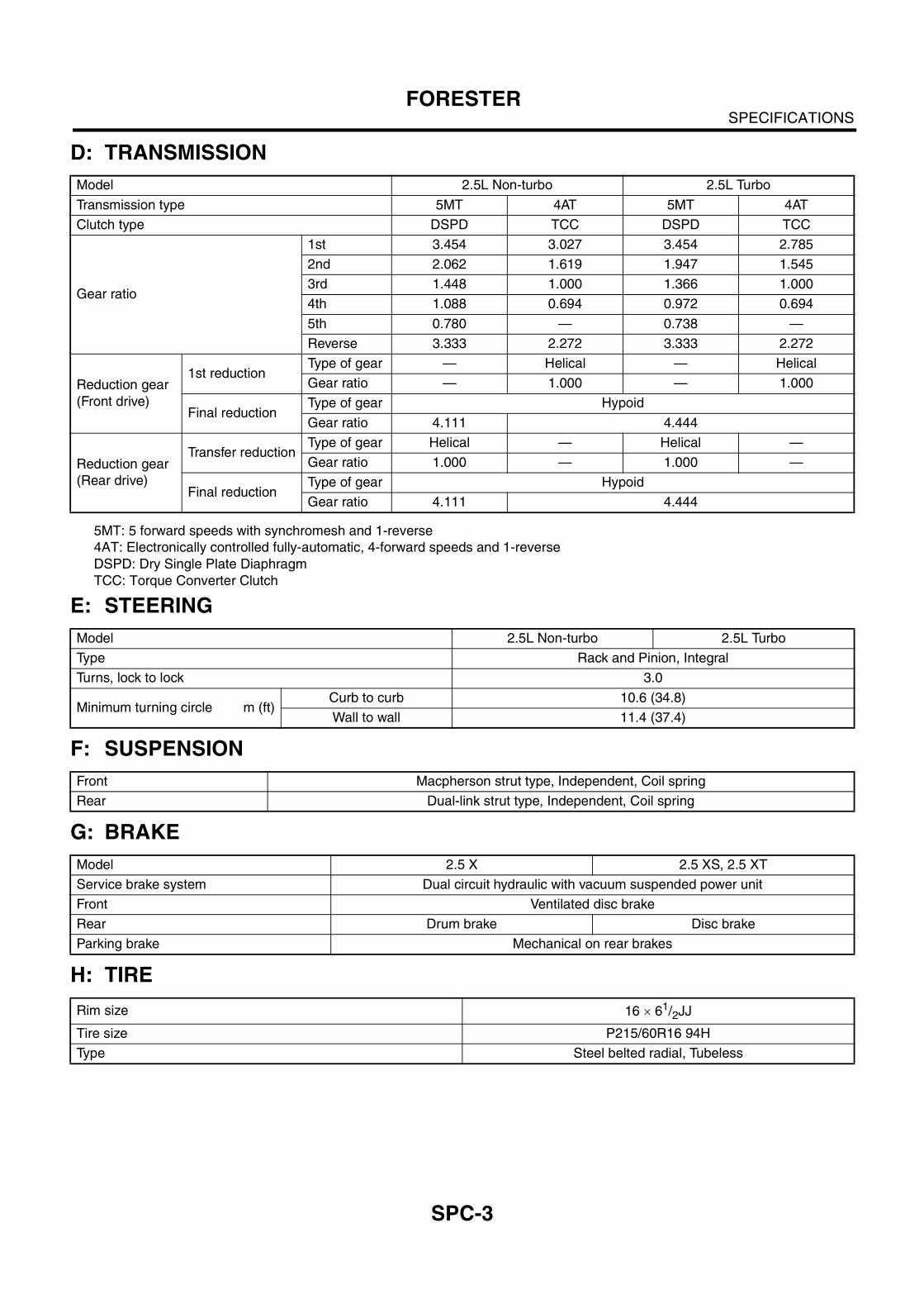
D: TRANSMISSION
5MT: 5 forward speeds with synchromesh and 1-reverse
4AT: Electronically controlled fully-automatic, 4-forward speeds and 1-reverse
DSPD: Dry Single Plate Diaphragm
TCC: Torque Converter Clutch
E: STEERING
F: SUSPENSION
G: BRAKE
H: TIRE
Model 2.5L Non-turbo 2.5L Turbo
Transmission type 5MT 4AT 5MT 4AT
Clutch type DSPD TCC DSPD TCC
Gear ratio
1st 3.454 3.027 3.454 2.785
2nd 2.062 1.619 1.947 1.545
3rd 1.448 1.000 1.366 1.000
4th 1.088 0.694 0.972 0.694
5th 0.780 — 0.738 —
Reverse 3.333 2.272 3.333 2.272
Reduction gear
(Front drive)
1st reductionType of gear — Helical — Helical
Gear ratio — 1.000 — 1.000
Final reductionType of gear Hypoid
Gear ratio 4.111 4.444
Reduction gear
(Rear drive)
Transfer reductionType of gear Helical — Helical —
Gear ratio 1.000 — 1.000 —
Final reductionType of gear Hypoid
Gear ratio 4.111 4.444
Model 2.5L Non-turbo 2.5L Turbo
Type Rack and Pinion, Integral
Turns, lock to lock 3.0
Minimum turning circle m (ft)Curb to curb 10.6 (34.8)
Wall to wall 11.4 (37.4)
Front Macpherson strut type, Independent, Coil spring
Rear Dual-link strut type, Independent, Coil spring
Model 2.5 X 2.5 XS, 2.5 XT
Service brake system Dual circuit hydraulic with vacuum suspended power unit
Front Ventilated disc brake
Rear Drum brake Disc brake
Parking brake Mechanical on rear brakes
Rim size 16 ! 61/2JJ
Tire size P215/60R16 94H
Type Steel belted radial, Tubeless
SPC-4
SPECIFICATIONSFORESTER
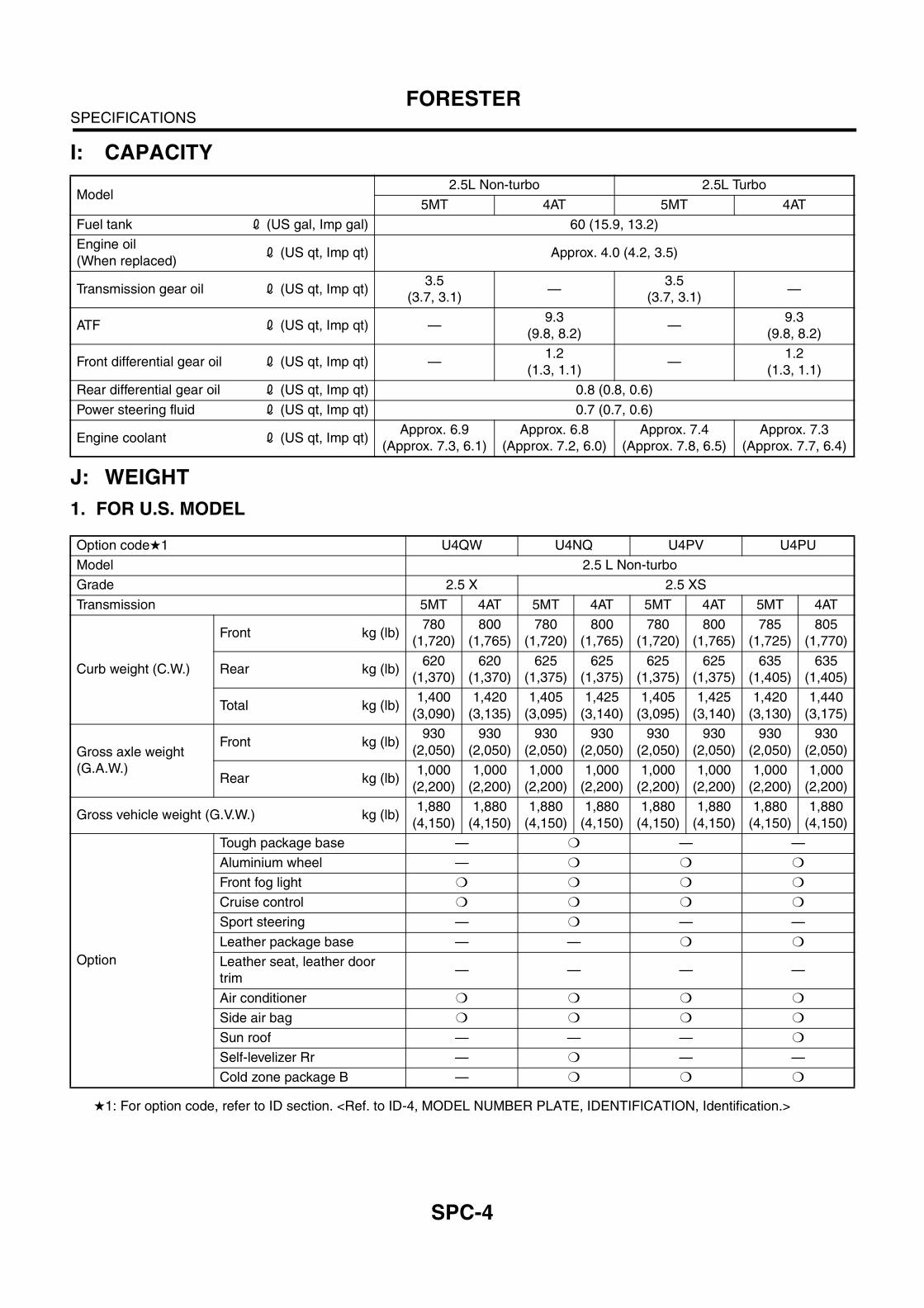
I: CAPACITY
J: WEIGHT
1. FOR U.S. MODEL
H1: For option code, refer to ID section. <Ref. to ID-4, MODEL NUMBER PLATE, IDENTIFICATION, Identification.>
Model2.5L Non-turbo 2.5L Turbo
5MT 4AT 5MT 4AT
Fuel tank 2 (US gal, Imp gal) 60 (15.9, 13.2)
Engine oil
(When replaced)2 (US qt, Imp qt) Approx. 4.0 (4.2, 3.5)
Transmission gear oil 2 (US qt, Imp qt)3.5
(3.7, 3.1)—
3.5
(3.7, 3.1)—
ATF 2 (US qt, Imp qt) —9.3
(9.8, 8.2)—
9.3
(9.8, 8.2)
Front differential gear oil 2 (US qt, Imp qt) —1.2
(1.3, 1.1)—
1.2
(1.3, 1.1)
Rear differential gear oil 2 (US qt, Imp qt) 0.8 (0.8, 0.6)
Power steering fluid 2 (US qt, Imp qt) 0.7 (0.7, 0.6)
Engine coolant 2 (US qt, Imp qt)Approx. 6.9
(Approx. 7.3, 6.1)
Approx. 6.8
(Approx. 7.2, 6.0)
Approx. 7.4
(Approx. 7.8, 6.5)
Approx. 7.3
(Approx. 7.7, 6.4)
Option codeH1 U4QW U4NQ U4PV U4PU
Model 2.5 L Non-turbo
Grade 2.5 X 2.5 XS
Transmission 5MT 4AT 5MT 4AT 5MT 4AT 5MT 4AT
Curb weight (C.W.)
Front kg (lb)780
(1,720)
800
(1,765)
780
(1,720)
800
(1,765)
780
(1,720)
800
(1,765)
785
(1,725)
805
(1,770)
Rear kg (lb)620
(1,370)
620
(1,370)
625
(1,375)
625
(1,375)
625
(1,375)
625
(1,375)
635
(1,405)
635
(1,405)
Total kg (lb)1,400
(3,090)
1,420
(3,135)
1,405
(3,095)
1,425
(3,140)
1,405
(3,095)
1,425
(3,140)
1,420
(3,130)
1,440
(3,175)
Gross axle weight
(G.A.W.)
Front kg (lb)930
(2,050)
930
(2,050)
930
(2,050)
930
(2,050)
930
(2,050)
930
(2,050)
930
(2,050)
930
(2,050)
Rear kg (lb)1,000
(2,200)
1,000
(2,200)
1,000
(2,200)
1,000
(2,200)
1,000
(2,200)
1,000
(2,200)
1,000
(2,200)
1,000
(2,200)
Gross vehicle weight (G.V.W.) kg (lb)1,880
(4,150)
1,880
(4,150)
1,880
(4,150)
1,880
(4,150)
1,880
(4,150)
1,880
(4,150)
1,880
(4,150)
1,880
(4,150)
Option
Tough package base — m — —
Aluminium wheel — m m m
Front fog light m m m m
Cruise control m m m m
Sport steering — m — —
Leather package base — — m m
Leather seat, leather door
trim— — — —
Air conditioner m m m m
Side air bag m m m m
Sun roof — — — m
Self-levelizer Rr — m — —
Cold zone package B — m m m
SPC-5
SPECIFICATIONSFORESTER
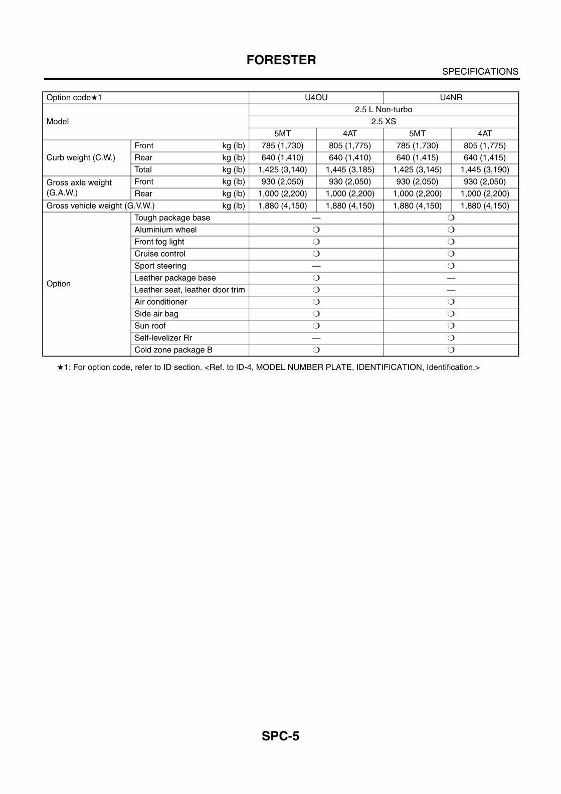
H1: For option code, refer to ID section. <Ref. to ID-4, MODEL NUMBER PLATE, IDENTIFICATION, Identification.>
Option codeH1 U4OU U4NR
Model
2.5 L Non-turbo
2.5 XS
5MT 4AT 5MT 4AT
Curb weight (C.W.)
Front kg (lb) 785 (1,730) 805 (1,775) 785 (1,730) 805 (1,775)
Rear kg (lb) 640 (1,410) 640 (1,410) 640 (1,415) 640 (1,415)
Total kg (lb) 1,425 (3,140) 1,445 (3,185) 1,425 (3,145) 1,445 (3,190)
Gross axle weight
(G.A.W.)
Front kg (lb) 930 (2,050) 930 (2,050) 930 (2,050) 930 (2,050)
Rear kg (lb) 1,000 (2,200) 1,000 (2,200) 1,000 (2,200) 1,000 (2,200)
Gross vehicle weight (G.V.W.) kg (lb) 1,880 (4,150) 1,880 (4,150) 1,880 (4,150) 1,880 (4,150)
Option
Tough package base — m
Aluminium wheel m m
Front fog light m m
Cruise control m m
Sport steering — m
Leather package base m —
Leather seat, leather door trim m —
Air conditioner m m
Side air bag m m
Sun roof m m
Self-levelizer Rr — m
Cold zone package B m m
SPC-6
SPECIFICATIONSFORESTER
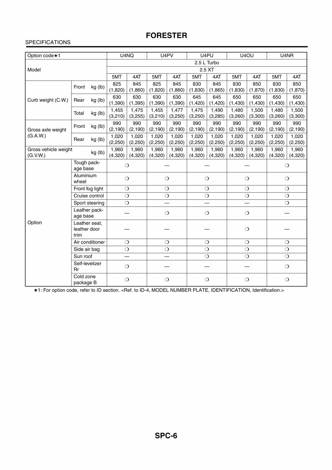
H1: For option code, refer to ID section. <Ref. to ID-4, MODEL NUMBER PLATE, IDENTIFICATION, Identification.>
Option codeH1 U4NQ U4PV U4PU U4OU U4NR
Model
2.5 L Turbo
2.5 XT
5MT 4AT 5MT 4AT 5MT 4AT 5MT 4AT 5MT 4AT
Curb weight (C.W.)
Front kg (lb)825
(1,820)
845
(1,860)
825
(1,820)
845
(1,860)
830
(1,830)
845
(1,865)
830
(1,830)
850
(1,870)
830
(1,830)
850
(1,870)
Rear kg (lb)630
(1,390)
630
(1,395)
630
(1,390)
630
(1,390)
645
(1,420)
645
(1,420)
650
(1,430)
650
(1,430)
650
(1,430)
650
(1,430)
Total kg (lb)1,455
(3,210)
1,475
(3,255)
1,455
(3,210)
1,477
(3,250)
1,475
(3,250)
1,490
(3,285)
1,480
(3,260)
1,500
(3,300)
1,480
(3,260)
1,500
(3,300)
Gross axle weight
(G.A.W.)
Front kg (lb)990
(2,190)
990
(2,190)
990
(2,190)
990
(2,190)
990
(2,190)
990
(2,190)
990
(2,190)
990
(2,190)
990
(2,190)
990
(2,190)
Rear kg (lb)1,020
(2,250)
1,020
(2,250)
1,020
(2,250)
1,020
(2,250)
1,020
(2,250)
1,020
(2,250)
1,020
(2,250)
1,020
(2,250)
1,020
(2,250)
1,020
(2,250)
Gross vehicle weight
(G.V.W.)kg (lb)
1,960
(4,320)
1,960
(4,320)
1,960
(4,320)
1,960
(4,320)
1,960
(4,320)
1,960
(4,320)
1,960
(4,320)
1,960
(4,320)
1,960
(4,320)
1,960
(4,320)
Option
Tough pack-
age basem — — — m
Aluminium
wheelm m m m m
Front fog light m m m m m
Cruise control m m m m m
Sport steering m — — — m
Leather pack-
age base— m m m —
Leather seat,
leather door
trim
— — — m —
Air conditioner m m m m m
Side air bag m m m m m
Sun roof — — m m m
Self-levelizer
Rrm — — — m
Cold zone
package Bm m m m m
SPC-7
SPECIFICATIONSFORESTER
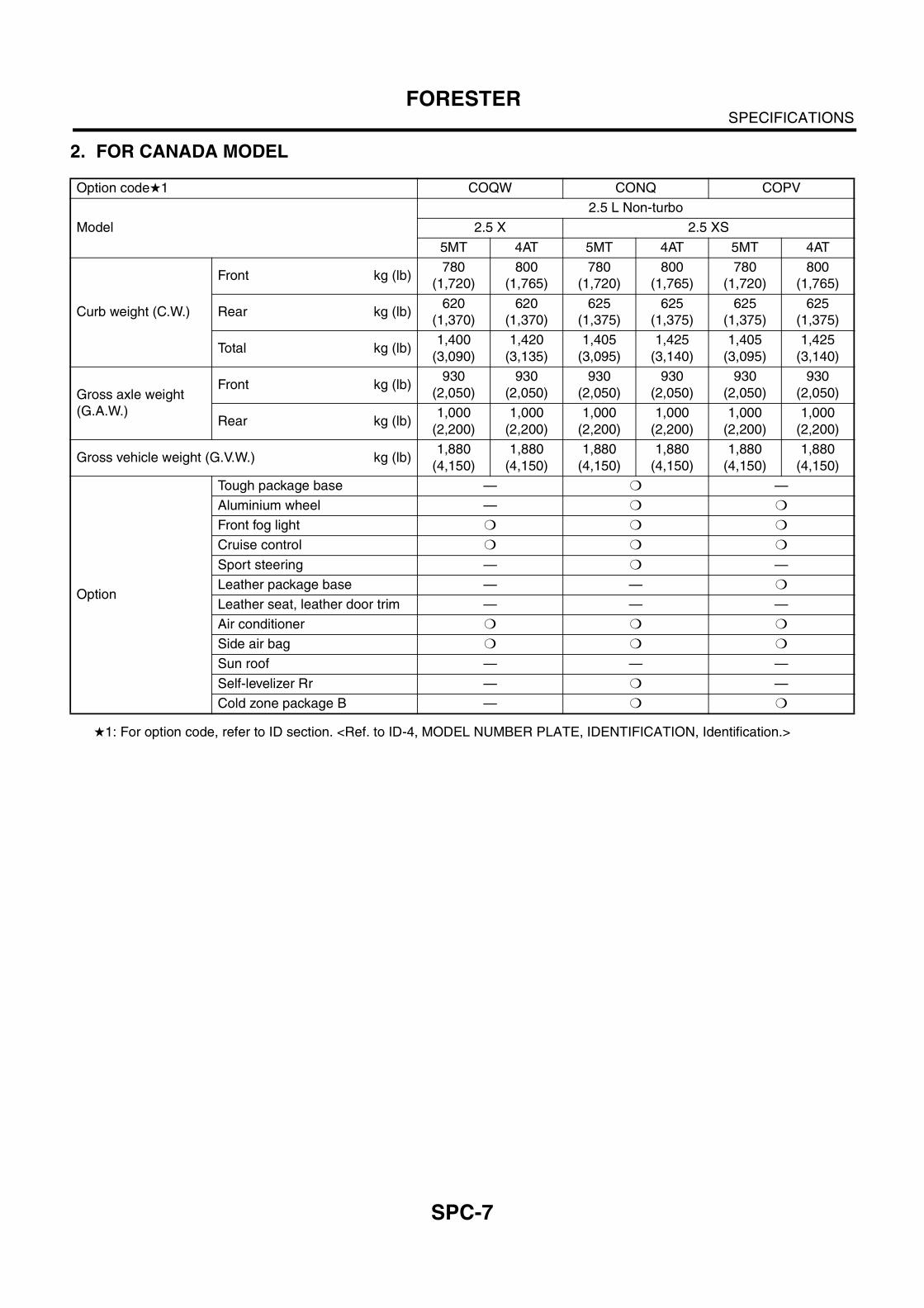
2. FOR CANADA MODEL
H1: For option code, refer to ID section. <Ref. to ID-4, MODEL NUMBER PLATE, IDENTIFICATION, Identification.>
Option codeH1 COQW CONQ COPV
Model
2.5 L Non-turbo
2.5 X 2.5 XS
5MT 4AT 5MT 4AT 5MT 4AT
Curb weight (C.W.)
Front kg (lb)780
(1,720)
800
(1,765)
780
(1,720)
800
(1,765)
780
(1,720)
800
(1,765)
Rear kg (lb)620
(1,370)
620
(1,370)
625
(1,375)
625
(1,375)
625
(1,375)
625
(1,375)
Total kg (lb)1,400
(3,090)
1,420
(3,135)
1,405
(3,095)
1,425
(3,140)
1,405
(3,095)
1,425
(3,140)
Gross axle weight
(G.A.W.)
Front kg (lb)930
(2,050)
930
(2,050)
930
(2,050)
930
(2,050)
930
(2,050)
930
(2,050)
Rear kg (lb)1,000
(2,200)
1,000
(2,200)
1,000
(2,200)
1,000
(2,200)
1,000
(2,200)
1,000
(2,200)
Gross vehicle weight (G.V.W.) kg (lb)1,880
(4,150)
1,880
(4,150)
1,880
(4,150)
1,880
(4,150)
1,880
(4,150)
1,880
(4,150)
Option
Tough package base — m —
Aluminium wheel — m m
Front fog light m m m
Cruise control m m m
Sport steering — m —
Leather package base — — m
Leather seat, leather door trim — — —
Air conditioner m m m
Side air bag m m m
Sun roof — — —
Self-levelizer Rr — m —
Cold zone package B — m m
SPC-8
SPECIFICATIONSFORESTER
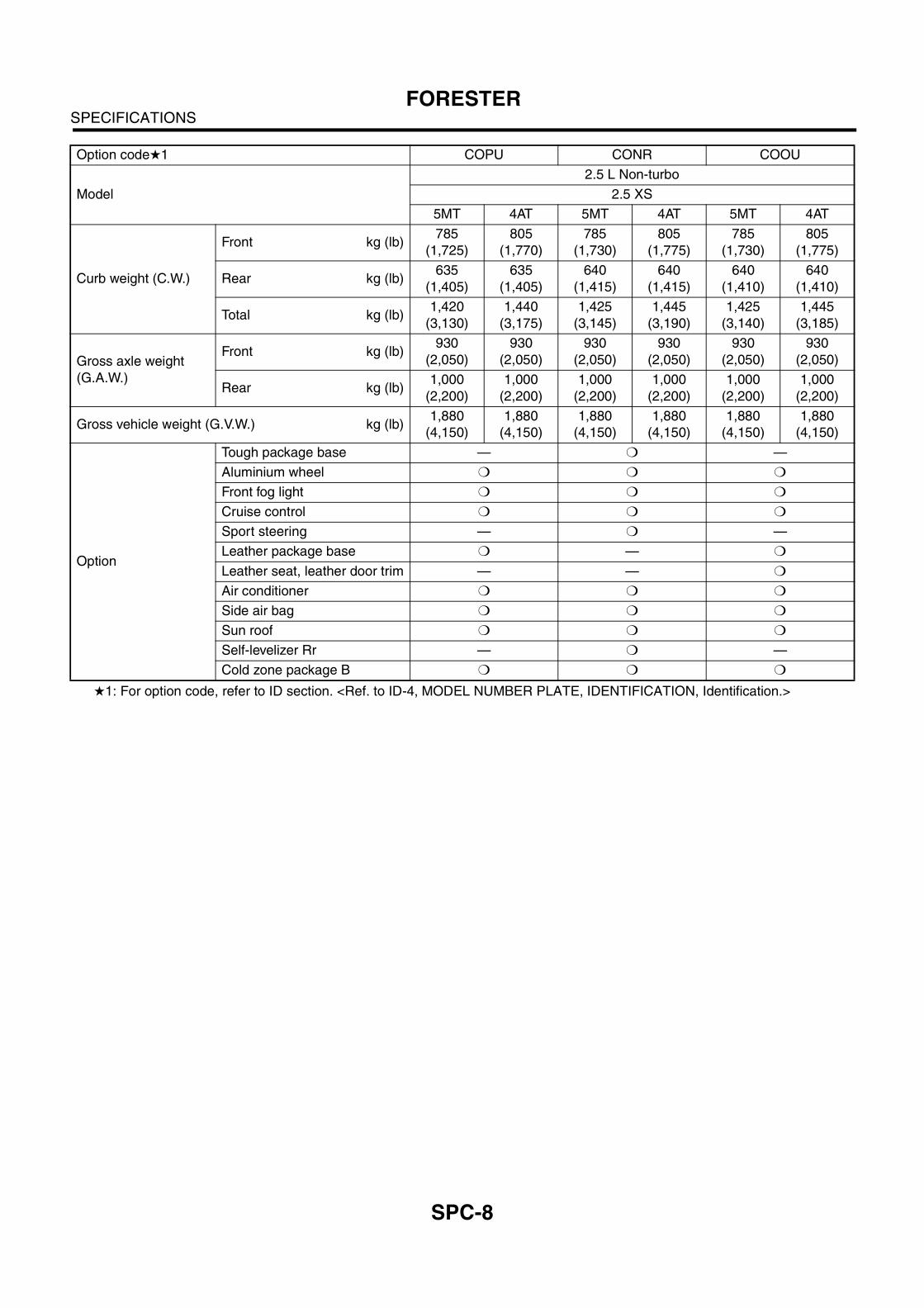
H1: For option code, refer to ID section. <Ref. to ID-4, MODEL NUMBER PLATE, IDENTIFICATION, Identification.>
Option codeH1 COPU CONR COOU
Model
2.5 L Non-turbo
2.5 XS
5MT 4AT 5MT 4AT 5MT 4AT
Curb weight (C.W.)
Front kg (lb)785
(1,725)
805
(1,770)
785
(1,730)
805
(1,775)
785
(1,730)
805
(1,775)
Rear kg (lb)635
(1,405)
635
(1,405)
640
(1,415)
640
(1,415)
640
(1,410)
640
(1,410)
Total kg (lb)1,420
(3,130)
1,440
(3,175)
1,425
(3,145)
1,445
(3,190)
1,425
(3,140)
1,445
(3,185)
Gross axle weight
(G.A.W.)
Front kg (lb)930
(2,050)
930
(2,050)
930
(2,050)
930
(2,050)
930
(2,050)
930
(2,050)
Rear kg (lb)1,000
(2,200)
1,000
(2,200)
1,000
(2,200)
1,000
(2,200)
1,000
(2,200)
1,000
(2,200)
Gross vehicle weight (G.V.W.) kg (lb)1,880
(4,150)
1,880
(4,150)
1,880
(4,150)
1,880
(4,150)
1,880
(4,150)
1,880
(4,150)
Option
Tough package base — m —
Aluminium wheel m m m
Front fog light m m m
Cruise control m m m
Sport steering — m —
Leather package base m — m
Leather seat, leather door trim — — m
Air conditioner m m m
Side air bag m m m
Sun roof m m m
Self-levelizer Rr — m —
Cold zone package B m m m
SPC-9
SPECIFICATIONSFORESTER
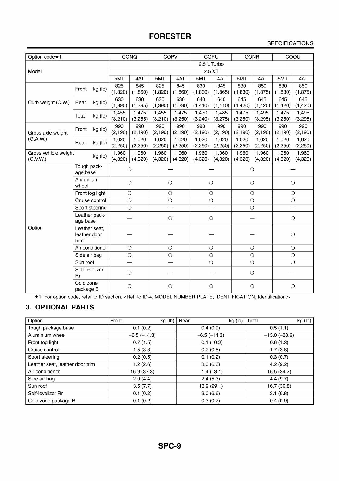
H1: For option code, refer to ID section. <Ref. to ID-4, MODEL NUMBER PLATE, IDENTIFICATION, Identification.>
3. OPTIONAL PARTS
Option codeH1 CONQ COPV COPU CONR COOU
Model
2.5 L Turbo
2.5 XT
5MT 4AT 5MT 4AT 5MT 4AT 5MT 4AT 5MT 4AT
Curb weight (C.W.)
Front kg (lb)825
(1,820)
845
(1,860)
825
(1,820)
845
(1,860)
830
(1,830)
845
(1,865)
830
(1,830)
850
(1,875)
830
(1,830)
850
(1,875)
Rear kg (lb)630
(1,390)
630
(1,395)
630
(1,390)
630
(1,390)
640
(1,410)
640
(1,410)
645
(1,420)
645
(1,420)
645
(1,420)
645
(1,420)
Total kg (lb)1,455
(3,210)
1,475
(3,255)
1,455
(3,210)
1,475
(3,250)
1,470
(3,240)
1,485
(3,275)
1,475
(3,250)
1,495
(3,295)
1,475
(3,250)
1,495
(3,295)
Gross axle weight
(G.A.W.)
Front kg (lb)990
(2,190)
990
(2,190)
990
(2,190)
990
(2,190)
990
(2,190)
990
(2,190)
990
(2,190)
990
(2,190)
990
(2,190)
990
(2,190)
Rear kg (lb)1,020
(2,250)
1,020
(2,250)
1,020
(2,250)
1,020
(2,250)
1,020
(2,250)
1,020
(2,250)
1,020
(2,250)
1,020
(2,250)
1,020
(2,250)
1,020
(2,250)
Gross vehicle weight
(G.V.W.)kg (lb)
1,960
(4,320)
1,960
(4,320)
1,960
(4,320)
1,960
(4,320)
1,960
(4,320)
1,960
(4,320)
1,960
(4,320)
1,960
(4,320)
1,960
(4,320)
1,960
(4,320)
Option
Tough pack-
age basem — — m —
Aluminium
wheelm m m m m
Front fog light m m m m m
Cruise control m m m m m
Sport steering m — — m —
Leather pack-
age base— m m — m
Leather seat,
leather door
trim
— — — — m
Air conditioner m m m m m
Side air bag m m m m m
Sun roof — — m m m
Self-levelizer
Rrm — — m —
Cold zone
package Bm m m m m
Option Front kg (lb) Rear kg (lb) Total kg (lb)
Tough package base 0.1 (0.2) 0.4 (0.9) 0.5 (1.1)
Aluminium wheel $6.5 ($14.3) $6.5 ($14.3) $13.0 ($28.6)
Front fog light 0.7 (1.5) $0.1 ($0.2) 0.6 (1.3)
Cruise control 1.5 (3.3) 0.2 (0.5) 1.7 (3.8)
Sport steering 0.2 (0.5) 0.1 (0.2) 0.3 (0.7)
Leather seat, leather door trim 1.2 (2.6) 3.0 (6.6) 4.2 (9.2)
Air conditioner 16.9 (37.3) $1.4 ($3.1) 15.5 (34.2)
Side air bag 2.0 (4.4) 2.4 (5.3) 4.4 (9.7)
Sun roof 3.5 (7.7) 13.2 (29.1) 16.7 (36.8)
Self-levelizer Rr 0.1 (0.2) 3.0 (6.6) 3.1 (6.8)
Cold zone package B 0.1 (0.2) 0.3 (0.7) 0.4 (0.9)
SPC-10
SPECIFICATIONSFORESTER