Embed Size (px)
Citation preview
42 | P a g e
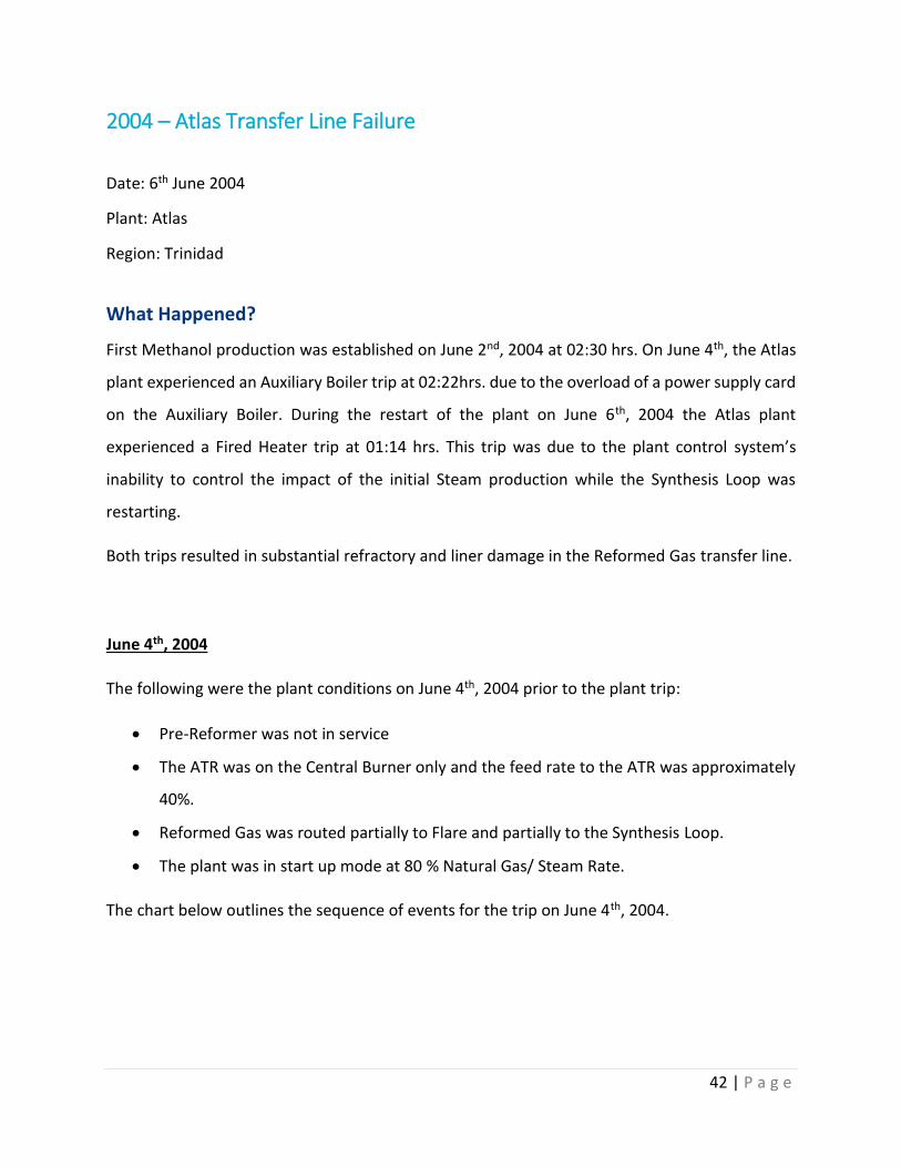
2004 – Atlas Transfer Line Failure
Date: 6th June 2004
Plant: Atlas
Region: Trinidad
What Happened?
First Methanol production was established on June 2nd, 2004 at 02:30 hrs. On June 4th, the Atlas
plant experienced an Auxiliary Boiler trip at 02:22hrs. due to the overload of a power supply card
on the Auxiliary Boiler. During the restart of the plant on June 6th, 2004 the Atlas plant
experienced a Fired Heater trip at 01:14 hrs. This trip was due to the plant control system’s
inability to control the impact of the initial Steam production while the Synthesis Loop was
restarting.
Both trips resulted in substantial refractory and liner damage in the Reformed Gas transfer line.
June 4th, 2004
The following were the plant conditions on June 4th, 2004 prior to the plant trip:
• Pre-Reformer was not in service
• The ATR was on the Central Burner only and the feed rate to the ATR was approximately
40%.
• Reformed Gas was routed partially to Flare and partially to the Synthesis Loop.
• The plant was in start up mode at 80 % Natural Gas/ Steam Rate.
The chart below outlines the sequence of events for the trip on June 4th, 2004.

43 | P a g e
2:23:08
• The Auxiliary Boiler trips due to power supply card circuit electrical overload duirng attempts to reset the ATR Satellite Burner.
• This causes the High Pressure Steam header to begin to fall, since the Aux boiler is supplying most of the High Pressure Steam, and as a result the ASU supplies less Oxygen.
2:24:51
• The Operator switches the Sweet Cooling Water Pump from the Turbine to Electric driven to conserve Steam.
• The MP header pressure begins to rise again and results in the Waste Heat Boiler Steam generation to fall.
2:25:41
• The Autothermal Reformer (ATR) trips on low Oxygen as a result of lower oxygen supply from the Air Separation Unit (ASU).
• The Synthesis Gas Compressor trips via interlock to ATR.
• The Synthesis Gas Compressor trip results in an increase in the Reformer Gas Pressure and further upsets the Process Steam Header.
2:25:46
• The ATR trip causes the Fired Heater Satellite Burners to close via interlock.
• This results in instability in the Fired Heater Fuel Header
• The Fired Heater Central Burner tripped on low pressure
2:25:50
• The ATR trip also closes the Feed Gas / Steam to the ATR.
• The Feed Gas and Steam to the ATR closes and causes a pressure increase in the Feed Gas and Steam header. This in turn results in the Feed Gas Flow to the Steam Reformer increasing.

44 | P a g e
2:25:50
•The Steam to Carbon ratio trip, resulted from inreased Feed Gas flow to the Primary Reformer.
•The Steam to Carbon ratio controller was not in control and the Reformed Gas to Flare valve is automatically closed after a 3 second delay causing the Reformer pressure to rise.
2:25:50
•Steam purge of Reformer equipment.
•FC-10704 (process steam to steam reformer) output decreases to 5% for 30 seconds then to 0%.
2:26:13
•The Operator opens the Reformed Gas valve to flare 34% over a 20 second period to reduce the Reformer pressures and switches it to Auto.
2:28:57
•The Reformed Gas valve to Flare drifted closed.
•The Reformed Gas pressure begins to increase again.
2:44:56
•The Operator adjusted the Reformed Gas to Flare PIC11331 set point from 20 barg to 16 barg and subsequently to 10 barg over a 4 minute period.
•The Reformed Gas pressure decreased in a controlled maner at a maximum rate of specific volume change of 37% per minute.
2:50:51
•The Reformed Gas Valve to Flare drifted closed.

45 | P a g e
Figure 10: Key Steam Reformer Process Variables at The Time of the Trip on June 4th
Figure 11: Two stage Depressurization of the Steam Reformer
It should be noted that the Reformer Depressurization occurred in two distinct stages when
compared to the trip on June 6th where it occurred in one continuous step.
46 | P a g e
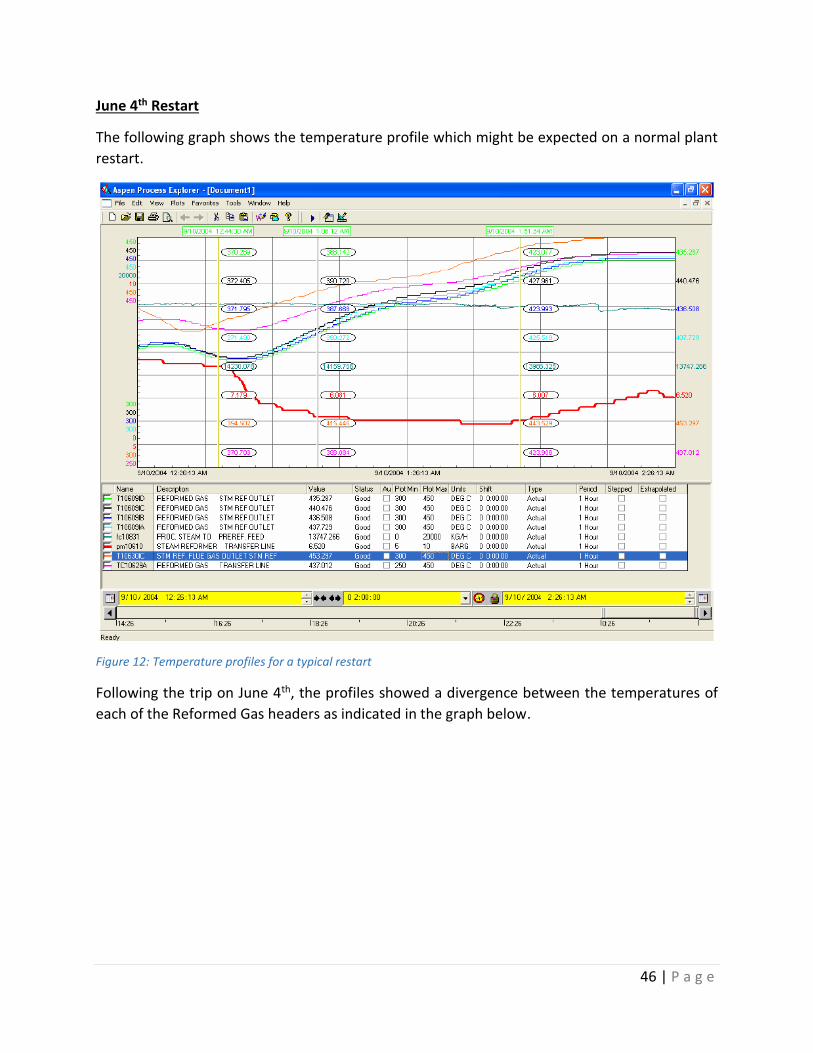
June 4th Restart
The following graph shows the temperature profile which might be expected on a normal plant
restart.
Figure 12: Temperature profiles for a typical restart
Following the trip on June 4th, the profiles showed a divergence between the temperatures of
each of the Reformed Gas headers as indicated in the graph below.

47 | P a g e
Figure 13: Temperature Profiles following the June 4th Trip
At the time of writing of the incident, the cause of the temperature variation was not determined.
However, it was suspected that the most likely cause was due to the liner refractory damage. It
was therefore presumed that the June 4th trip also caused damaged which did not lead to
hotspots. The damage was further compounded by the events of the June 6th trip.
June 6th, 2004
The following are the plant conditions on June 6th, 2004 prior to the plant trip:
• The Front End rate was approximately 80%
• Synthesis Gas feed to the Synthesis Loop was commencing
The over-riding characteristic of the events is that the Steam system controllers repeatedly failed
to accommodate any of the following upset conditions:

48 | P a g e
• The Fired Heater was unable to control the superheat temperature changes resulting
from commissioning the Synthesis Loop Reactors. This was since the HP Header mid-point
isolation valve was not opened. It was in the start up or closed position that is required
to allow the Auxiliary Boiler Steam to flow through the Fired Heater HP coils. The Steam
production from the Synthesis Loop backed out the Steam demand and reduced the start
up steam flow. One corrective action was to bring the Front End to a higher rate (greater
than 85%) and have the Steam System in normal operating mode prior to putting the loop
into service.
• The Auxiliary Boiler pressure control was unable to accommodate the increase in Steam
pressure resulting from the Fired Heater trip.
• The over pressure trip of the Auxiliary Boiler occurred despite the plant being severely
short of steam generation capacity.
• The differential pressure controller PDC 11331 interlock between the Process Steam
header and the Reformer pressure ensured the Reformer pressure fell at the same rate
as the Steam header pressure.
The following chart outlines the sequence of events which occurred on June 6th:
1:14:00
•Fired Heater trip due to high temperature on the HP Superheater outlet temperature (TI2513)
•ESD trip of Auxiliary Burner
1:14:00
•ESD trip of Autothermal Reformer
•ESD trip of Synthesis Gas Machine
•ESD trip of ASU
1:14:24 •Trip of Auxiliary Boiler
1:26:08
•Steam Reformer manually tripped by operator
•Natural Gas Compressor tripped
49 | P a g e
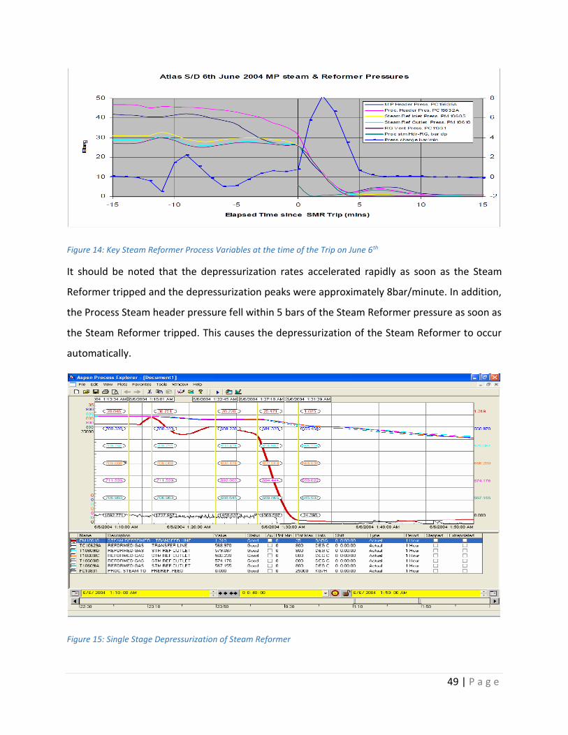
Figure 14: Key Steam Reformer Process Variables at the time of the Trip on June 6th
It should be noted that the depressurization rates accelerated rapidly as soon as the Steam
Reformer tripped and the depressurization peaks were approximately 8bar/minute. In addition,
the Process Steam header pressure fell within 5 bars of the Steam Reformer pressure as soon as
the Steam Reformer tripped. This causes the depressurization of the Steam Reformer to occur
automatically.
Figure 15: Single Stage Depressurization of Steam Reformer

50 | P a g e
The Steam Reformer depressurization occurred in one distinct stage when compared to the trip
on June 4th.
The diagram below outlines the sequence of events in the form of a thought map. This map shows
the interaction of many factors which contributed to the failure. The yellow asterisk denotes the
areas of limited plant dynamics understanding at the point of writing of the incident.
--
Figure 16: Diagrammatic representation the sequence of events on June 6th 2004.
The photos below show the as found inspection of the Transfer Line after the plant was shut
down.

51 | P a g e
Figure 17: As found inspection of the Atlas Transfer Line after plant shutdown
Failure Analysis
The following diagram shows the number of interacting issues that lead to the refractory and
liner failure.
Figure 18: Interacting issues that led to the Transfer Line failure.
The issues can be divided into three groups:

52 | P a g e
• Lack of adequate plant control, which caused the trip and lead to the rapid
depressurization
• The liner design and inability to allow the de-pressuring gas to exit into the main line
• The refractory material and installation
Each of these causes has its origins in the design of the plant and in the case of the rapid
depressurization, it was compounded by the absence of a procedure to ensure controlled
depressurization at acceptable rates. The design and operating instructions provided by Lurgi
gave no priority to achieving acceptable depressurization rates.
All three groups of issues shared a common factor, which is that the design is novel and not based
on previous proven experience. The driving force was for Atlas to achieve a higher single train
capacity.
• The process is significantly different to Titan and earlier plants because it is more complex,
which contributed to the control difficulties. The inter-relationship between the different
parts of the plant had not been appreciated adequately and so upsets in one part of the
plant quickly escalated into a plant wide shut down. The interlock system was designed
to allow most of the plant to remain online after one section trips. Unfortunately, the
controls were unable to stabilize the plant operation following such interlock actions.
• The refractory in the Reformed Gas main was new to this service for Lurgi (Licensor and
Engineering Company). The refractory choice was driven by a desire to reduce silica and
sodium content to address problems encountered on the Titan plant.
Recommendations
The following were the recommendations which were implemented after the incident:+
• Ensure that the Reformer is de-pressured in a controlled manner at about 1bar/minute
down to 15 barg and then at a slower rate down to 5 barg.
• Carry out a proper dynamic analysis of the plant steam system and associated equipment
to determine how to design the controls to accommodate interlock actions such that the

53 | P a g e
plant integrity is not compromised, and an acceptable Reformer depressurization is
achieved on Reformer shutdown. Some recommendations for such an activity might be:
o Eliminate PDC 11331
o Add flow follower on the PC94112 HP vent such that it pops open on an ASU or
Synthesis Gas Compressor Trip.
o Dump surplus HP Steam to the LP header and LP Header Vent.
o Cut Auxiliary Boiler firing immediately the ASU and the Synthesis Gas Compressor
trip.
o Develop a Reformer depressurization logic such that a controlled and not too rapid
Reformer depressurization occurs following a Reformer shut down at a rate of
about 1 bar/minute.
• Determine if the refractory material choice is optimum. A stronger material with lower
void fraction is preferred from the perspective of depressurization. It is accepted that
other requirements must also be satisfied such as insulating properties and weight.
• Redesign the Reformer Gas main collection headers and transfer line to accommodate
excessive depressurization rates which despite any control system can always occur. Such
redesign should consider the following factors:
o An unlined main would eliminate any depressurization issues since they also use
hard-faced refectory with lower void fraction and greater strength. Unlined mains
are widely used in the reforming industry with success. However, such a design is
not the Lurgi norm. detailed knowledge and successful experience are essential
for any modification, lined or unlined.
o If a liner is to be retained, ensure an adequate annulus gap between the liner and
the refractory.
o Ensure the distance between the expansion joints is not excessive.
o Ensure the expansion gap is sufficient.
o Ensure any new design offered has existing proven experience for the specific
configuration offered, including materials, dimensions and depressurization rates.

54 | P a g e
o Ensure that new problems are not introduced such as gas tracking behind the liner
and refractory and liner expansion is adequately allowed for.
o Ensure any new design proposed is a commercially proven configuration in similar
service.