Embed Size (px)
Citation preview
i510-411 www.powercommander.com 2004-2005 Triumph Rocket III - PCIII USB - 1
2004-2005 Triumph Rocket IIIInstallation Instructions
Dynojet Research 2191 Mendenhall Drive North Las Vegas, NV 89031 (800) 992-4993 www.powercommander.com
Parts List1 Power Commander1 USB Cable1 CD-ROM1 Installation Guide1 Power Adapter2 Power Commander Decals2 Dynojet Decals3 Velcro® Strip1 O2 controller1 Alcohol Swab
You can also download the PowerCommander software and latest mapsfrom our web site at:
www.powercommander.com
PLEASE READ ALL DIRECTIONS BEFORE STARTING INSTALLATION
Button Adjustment Display
Faceplate Buttons
Expansion Port USB Port
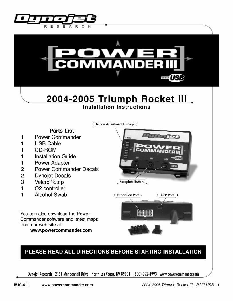
1 Remove the seat.
2 Prop the fuel tank up using thestock prop rod.
3 Remove the right hand sidecover.
4 Route the PCIII harness fromthe right hand side of the bikeunder the frame rail and towardsthe front of the bike (Fig. A).
5 Attach the ground wire from thePCIII to the negative side of thebattery (Fig. B).
6 Unplug the BLACK connectorfrom the throttle bodies to themain wiring harness (Fig.C). This connector is locatedunder the fuel tank towards thefront of the bike.
Fig.
AFi
g. B
Fig.
C
i510-411 www.powercommander.com 2004-2005 Triumph Rocket III - PCIII USB - 2
PCIII harness
PCIII harness
Ground wire from PCIII
Unplug this connector
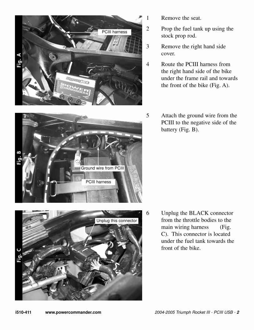
7 Plug the connectors from thePCIII in-line of the stock wiringharness and throttle bodies(Fig. D). Tuck the connectorstowards the front of the bike anddown as far as possible to clearthe fuel tank.
Fig.
D
i510-411 www.powercommander.com 2004-2005 Triumph Rocket III - PCIII USB - 3
Stock connectorsPCIII connectors
8 Unplug the connector from thestock O2 sensor. This connec-tion is under the right hand sidecover in front of the ECU(Fig. E).
Fig.
E
9 Plug the O2 controller into thestock wiring harness. The con-nector from the O2 sensor doesNOT have to be plugged intoanything.
10 Mount the O2 controller on topof the the relays using the sup-plied velcro (Fig. F).
Fig.
F
Unplug
O2 controller
Stock harness
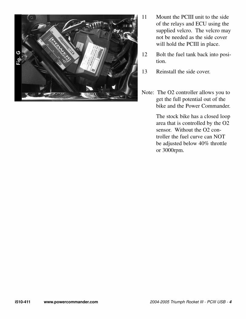
11 Mount the PCIII unit to the sideof the relays and ECU using thesupplied velcro. The velcro maynot be needed as the side coverwill hold the PCIII in place.
12 Bolt the fuel tank back into posi-tion.
13 Reinstall the side cover.
Note: The O2 controller allows you toget the full potential out of thebike and the Power Commander.
The stock bike has a closed looparea that is controlled by the O2sensor. Without the O2 con-troller the fuel curve can NOTbe adjusted below 40% throttleor 3000rpm.
Fig.
G
i510-411 www.powercommander.com 2004-2005 Triumph Rocket III - PCIII USB - 4