Embed Size (px)
Citation preview
Stealthbox®
I N S T A L L A T I O N G U I D E
SB-GM-HUMR2/12W6v2, JL AUDIO, Inc 2004 Sheet SKU#011182 Revis ion8/5/2004 Page 1
for the
SB-GM-HUMRH2/12W6v2(2003-Up Hummer H2)
This Stealthbox is a product whichrequires professional installation skills andtools.Please read this installation guide thor-oughly before beginning the project. Itwill guide you step by step through theinstallation. Several of the steps in thisprocess may require two people toaccomplish.
It is absolutely vital that the enclosurebe properly mounted to the vehicleaccording to these instructions. Failureto mount the enclosure properly pres-ents two problems: 1) The sub-bassperformance will suffer due to themovement of the enclosure caused bythe force exerted by the woofer(s) and2) A loose enclosure presents a serioussafety hazard in the event of a collisionor sudden deceleration.
Please enjoy your JL Audio Stealthboxresponsibly.
STEP 1: Remove the third “jump” seat. *STEPS 2-4 are for the vehicle that areequip with the internal spare tire.*
STEP 2: Remove the spare tire
STEP 3: Remove the jack and jack tools.
STEP 4: With an 8mm socket, remove thefour bolts that secure the spare tire rack.
STEP 5: By pulling up, remove the driver’sside rear storage bucket.
STEP 6: With a 10mm socket, flat headscrew driver, Phillips® head screw driver and aT-15 socket.
Remove the driver’s side rear wheel well plas-tic trim.
START HERE
Continued on Next Page
w w w . j l a u d i o . c o m

STEP 7: With the plastic trim out of the way,remove the plastic inner wheel well.
STEP 11: Thread the supplied pair of socket caset screws into the enclosure, leaving 1/2” exposed.
Place the enclosure into place and firmly pressdown.
Cont.From
PreviousPage
Continued on Next Page
STEP 8: Rest the plastic inner wheel well on therear tire. Keep the trim and all the mounting hard-ware together.
STEP 12: *CAUTION*
Before drilling, make sure that you are not going tobe drilling into any gas lines, brake lines, transmissionlines, electrical wiring, transfer case(4x4 vehicles) oranything else that might cause a reduction in yourweekly pay. Always wear eye protection whendrilling.
With the use of a 1/2” drill bit and drill. Drill out thefloor at the impression on the wax square.
STEP 13: Remove the wax square sheets from themounting area.
STEP 14: Run speaker wire to the enclosure loca-tion.
Also check the woofer for proper operation.
STEP 9: (Inside the vehicle) Cut and removethe factory jute(sound deadening), from theremoved storage area, from STEP 5.
STEP 10: Place the supplied pair of wax sheetsinto place.
Remember to remove the rear paper backing, fromthe wax sheets.
SB-GM-HUMR2/12W6v2, JL AUDIO, Inc 2004 Sheet SKU#011182 Revis ion8/5/2004 Page 2w w w . j l a u d i o . c o m

STEP 15: Back out the socket cup set screws, thatwas threaded in from STEP 11, to expose 1-1/4”.
Connect the speaker wire to the terminal and placethe enclosure into position.
STEP 19: With the spare tire rack placed intoposition. Loosely tighten the lower factory bolts tothe lower mounting feet.
Cont.From
PreviousPage
Continued on Next Page
STEP 16: (Outside the vehicle) Place the sup-plied hardware in order onto the exposed socketcup screw. If more exposed threads are needed, backout the socket cup set screws.
*Do not back out too much, you can cause aconflict when mounting the plastic innerwheel well, back into location.*
Fender washer, flat washer, lock washer and hex nutonto each socket cup set screw.
Secure tightly.
STEP 20: Placed A supplied spacer, between eachupper mounting foot of the spare tire rack and theside panel.
Loosely secure each upper mount assembly with asupplied hex cap screw.
STEP 21: Align the spare tire rack, for properpositioning.
STEP 22: With the spare tire rack properly posi-tioned, it should not interfere with the enclosure.
STEP 17: Mount the plastic inner wheel well andplastic trim from STEPS 6 & 7.
You didn’t leave too much of the socket cup setscrews exposed, did you?
*STEPS 18-24 are for only for the vehiclesthat are equip with the internal spare tire.*
STEP 18: The spare tire rack needs to be modi-fied for the proper spacing,This needs to be accom-plished on both bottom mounting feet.
Measure 9/16” from the center of the factorymounting hole, back. Mark and drill with the a 1/2”drill bit or Uni-bit®.
SB-GM-HUMR2/12W6v2, JL AUDIO, Inc 2004 Sheet SKU#011182 Revis ion8/5/2004 Page 3w w w . j l a u d i o . c o m
Specifications:Enclosure Type: SealedDriver Type: 12W6v2-D4Nominal Impedance: 2ΩCont. Power Handling: 400 Watts
JL Audio recommends using a high quality amplifier such as the JL Audio 500/1. The diagram below shows the recommendedcrossover, infrasonic filter and equalizer settings for the 500/1 when being used to power your Stealthbox®.
Included Hardware:(2) 3” x 3”Wax sheets(2) 3/8”-16 x 2-1/4” Socket Cup Set Screw(2) 3/8” x 1-1/4” Fender Washer(2) 3/8” USS Flat Washer(2) 3/8” - 16 HEx Nuts(2) 1/2”(w) x 1”(od) Spacers(2) 12mm x 70mm Hex Cap Screws
10369 N. Commerce Pkwy, Miramar, Florida 33025-392 Phone: 954.443.1100 Fax: 954.443.1111
+12VDC RemoteGround
JL AUDIO 500/1five-channel system amplifier
+ __+
Subwoofer Output
MONO OUTPUT ONLY40
45
5565
85
120
200
Filter Freq. (Hz)
Mode / Slope
Off / 12dB / 24dB
Amp LP Filter
Infrasonic Freq. (Hz)
15
18
2530
40
50
60
Off / 30Hz
Infrasonic Filter
0.5
0.7
1.11.6
2.7
4.3
"Q"
20
25
3545
55
70
85
Center Freq.
0
+4+10
+13
+15
Boost (dB)
Off / On
Bass EQ
Remote Bass Port
AdvancedBassControl
Preamp Output Section
Full Range / Amp Filter / Out Filter
Output Mode Filter Slope
12dB / 24dB
40
45
5565
85
120
200
Filter Freq. (Hz)Left Ch. Right Ch.
Filter Mode
LP / HP
Amplifier Input Section
Input Sens.
Left Ch. Right Ch.
Signal Sensing
Off / On
Input Voltage
Low / High
The JL Audio 500/1 is a very versatile audio component. Please consult the owner’s manual for detailed informationabout installing and tuning this amplifier.
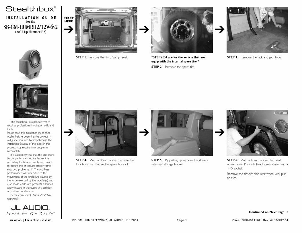
STEP 23: Replace the jack and the jack tools, thatwere removed in STEP 3.
STEP 24: Secure the spare tire onto the rack andreplace the tire cover.
SB-GM-HUMR2/12W6v2, JL AUDIO, Inc 2004 Sheet SKU#011182 Revis ion8/5/2004 Page 4w w w . j l a u d i o . c o m
Mid/High Frequency Driver Information:
CONGRATULATIONS!INSTALL COMPLETE.
ZR650-CSi
XR525-CXi
Front Location Driver Size:6.5”(door) & Tweeter(A-pillar)
Applicable JL Audio Products:TR,VR, XR, ZR 650-CSi
Rear Door Location Driver Size:5.25”
Applicable JL Audio Products:TR,VR, XR525-CXi
Rear Cargo Location Driver Size:2.25”
Applicable JL Audio Products:N/A
Cont.From
PreviousPage
Difficulty Of Installation: