Embed Size (px)
Citation preview
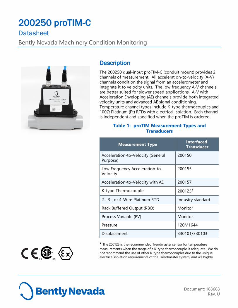
DescriptionThe 200250 dual-input proTIM-C (conduit mount) provides 2 channels of measurement. All acceleration-to-velocity (A-V) channels condition the signal from an accelerometer and integrate it to velocity units. The low frequency A-V channels are better suited for slower speed applications. A-V with Acceleration Enveloping (AE) channels provide both integrated velocity units and advanced AE signal conditioning. Temperature channel types include K-type thermocouples and 100Ω Platinum (Pt) RTDs with electrical isolation. Each channel is independent and specified when the proTIM is ordered.
Table 1: proTIM Measurement Types and Transducers
Measurement Type Interfaced Transducer
Acceleration-to-Velocity (General Purpose)
200150
Low Frequency Acceleration-to-Velocity
200155
Acceleration-to-Velocity with AE 200157
K-type Thermocouple 200125*
2-, 3-, or 4-Wire Platinum RTD Industry standard
Rack Buffered Output (RBO) Monitor
Process Variable (PV) Monitor
Pressure 120M1644
Displacement 330101/330103
* The 200125 is the recommended Trendmaster sensor for temperature measurements when the range of a K-type thermocouple is adequate. We do not recommend the use of other K-type thermocouples due to the unique electrical isolation requirements of the Trendmaster system, and we highly
Document: 163663Rev. U
200250 proTIM-CDatasheetBently Nevada Machinery Condition Monitoring

recommend the use of only non-grounded RTDs and non-grounded tip thermocouples to prevent ground loops. Failure to comply may result in Not OK or NO DATA conditions, inaccurate readings, or proTIM-C damage. Consult Bently Nevada, LLC for further information.
SpecificationsAll specifications are at +25 ± 5 °C (+77 ± 9 °F) unless otherwise specified. Operation outside the specified limits will result in false or inaccurate readings.
Table 2: proTIM and Transducers Frequency Responses
Device Lower Freq Upper Freq
200250-01 1 Hz 1 KHz
200250-05 1 Hz 1 KHz
200250-06 AV 1 Hz 1 KHz 1
200250-06 AE 1 Hz 500 Hz1
200150 XDCR 10 Hz 1 KHz
200155 XDCR 3 Hz 10 KHz2
200157 XDCR 10 Hz 10 KHz
1 2002XX-06 proTIM AE circuitry allows enveloping input frequency up to 10 KHz.
2 200155 has a long settling time. Therefore, it should only be used for low frequency acceleration to velocity channel types.
200250 proTIM-C and 200150, 200155, 200157 or 200125 transducer systems
For detailed specification on the transducers, refer to the individual transducer data sheets.
Electrical A–V (General Purpose) Channels (with 200150)
Measurement 0 to 50 mm/s pk (0 to 2 in/s pk)
Range
Over Range 63 mm/s pk (2.5 in/s pk)
Resolution 0.025 mm/s (0.001 in/s pk) nominal
Accuracy ±15% at 80 Hz
Frequency Response1
10 Hz to 1 kHz (600 cpm to 60,000 cpm) ±20% (± 2 dB).1 This Frequency response represents the System proTIM & Transducer. For details on individual device frequency response refer to See "proTIM and Transducers Frequency Responses " above
Not OK Range
Open transducer signal, power, or common is “Not OK”. Shorted leads are “Not OK” except for SIG+ shorted to SIG- or common shorted to shield.
Low Frequency A–V Channels (with 200155)
Measurement Range
0 to 50 mm/s pk (0 to 2 in/s pk)
Over Range 63 mm/s pk (2.5 in/s pk)
Resolution 0.025 mm/s (0.001 in/s pk) nominal
Accuracy ±15% at 80 Hz
Frequency Response1
3 Hz to 1 kHz (180 cpm to 60,000 cpm) ± 10% (±0.9 dB) 2. 1 This Frequency response represents the System ProTIM & Transducer. For details on individual device frequency response refer to See "proTIM and Transducers Frequency Responses " above
2 The A-V circuitry attenuates frequencies above 1 kHz. Use of the 200155 transducer to obtain higher frequency information will be ineffective.
Not OK Range
Open transducer signal, power, or common is “Not OK”. Shorted leads are “Not OK” except for SIG+ shorted to SIG- or common shorted to shield.
A–V w/ AE Channels (with 200157)
Measurement Range
0 to 50 mm/s pk (0 to 2 in/s pk)
200250 proTIM-CDatasheet
2/13 163663 Rev. U

Over Range 63 mm/s pk (2.5 in/s pk)
Resolution 0.025 mm/s (0.001 in/s pk) nominal
Accuracy ±15% at 80 Hz
Frequency Response1
A-V 10 Hz to 1 kHz (600 cpm to 60,000 cpm) ± 20% (± 2.0 dB) 2. See "proTIM and Transducers Frequency Responses " on the previous page
AE 10 Hz to 500 Hz (600 cpm to 30,000 cpm) ± 20% (±2.0 dB) 3
1 This Frequency response represents the System proTIM & Transducer. For details on individual device frequency response, See "proTIM and Transducers Frequency Responses " on the previous page
2 The A-V circuitry attenuates frequencies above 1 kHz. Use of the 200157 transducer to obtain higher frequency information will be ineffective. AE signals up to 10 kHz are processed at the proTIM.3 The 500 Hz filter has a 4-pole attenuation slope. The enveloped signal will range between 1Hz to 500 Hz.
Not OK Range:
Open transducer signal, power, or common is “Not OK”. Shorted leads are “Not OK” except for SIG+ shorted to SIG- or common shorted to shield.
Table 3: proTIM and Transducers Compatibility
Device 200150 200155 200157
200250-01
Great N/A OK1
200250-05
OK2 Great OK2
200250-06
OK3 N/A Great
1 The proTIM does not offer AE capability and will only accept frequencies up to 1 KHz whereas 200157 will go up to 10 KHz. 2Lower transducer limit is 10 Hz, whereas 200155 will operate down to 3 Hz.3 The proTIM's AE circuit accepts frequencies up to 10 KHz, but 200150 operates only up to 1 KHz.
Temperature Channels
Measurement Range
-18 °C to +204 °C (0 °F to +400 °F)
Resolution 0.07 °C (0.12 °F)
Accuracy
K-Type TC ±8 °C (±14 °F), including proTIM-C, thermocouple & lead wire error, maximum length of 6 meters.
Maximum temperature ramp rate: ±0.5 °C/min.
RTD ±4.45 °C (±8 °F), RTD lead wire error not included
OK Range -31 °C to +213 °C (-25 °F to +415 °F)
Not OK Condition
Temperatures outside the OK Range
Open RTD or thermocouple wires are "Not OK"
RTD Compensation Coefficient Alpha in W/W/°C
European 0.00385
US Industrial 0.00392
Software Compensation
At host computer
Rack Buffered Output Channels
Measurement Range
AC: 1 Vpp to 8 Vpp full scale DC: 0 to –20 Vdc (See Table 2)
Table 4: Input Signal and Range
Input Signal Full Scale Overrange
LOAC_IN 1.6 Vpp 1.92 Vpp
HIAC_IN 8 Vpp 9.6 Vpp
DCGAP_IN DC: -20 VDC AC: 1 Vpp
DC: -24 VDC AC: 5.3 Vpp
Resolution AC: ±1% of full-scale value at 100 Hz DC: ±500 mV, absolute accuracy
Frequency Response
10Hz to 3 KHz (+0 to –5%)
Not OK Input signal is out of range,
200250 proTIM-CDatasheet
3/13 163663 Rev. U

Range Input signal miswired.
Process Variable Channels
Measurement Range
Current: +4 mA to +20 mAVoltage: +1 Vdc to 5 Vdc
Over Range Current: <+3 mA or >+22 mAVoltage: <+0.8 Vdc or >+5.5 Vdc
Resolution ±1% of full-scale value Typical
OK Range Current: Over +3.2 mAVoltage: Over 0.8 Vdc
Frequency Response
DC to 3 KHz
Pressure Channels
Measurement Range
0 to 50 mV
Resolution ±8.5% of the transducer full-scale rating (transducer accuracy not included)
OK Range 1 Vdc to 3 Vdc Bias from transducer
Frequency Response
Less than 3 KHz
Displacement Channels (with 330101/330103)
Input Used with our 3300 XL 8 mm probe or 3300 5 mm probe and extension cable (5 metre system) only.
Output Voltage Range
-3.0 to 3.0 V (Over Specified linear range)
Transducer Linear Range
10 to 50 mils (0.254 to 1.27 mm)
Scale Factor 120 mV/mil +/-10%
Accuracy Over Gap Range
+/-1.2 mils @ mid-scale range.
Frequency Response
DC to 3 KHz (0 to 180,000 cpm).
Minimum 15.2 mm (0.6 in) diameter (flat target)
Target size
Shaft Diameter:
Minimum: 50.8 mm (2 in)Recommended minimum: 76.2 mm (3 in)Measurements on shaft diameters smaller than 50 mm (2 in) usually require close spacing of radial vibration or axial position transducers with the potential for their electromagnetic emitted fields to interact with one another (cross-talk), resulting in erroneous readings. Care should be taken to maintain minimum separation of transducer tips, generally at least 40 mm (1.6 in) for axial position measurements or 74 mm (2.9 in) for radial vibration measurements. Radial vibration or position measurements on shaft diameters smaller than 76.2 mm (3 in) will generally result in a change in scale factor. Consult Performance Specification 159484 for additional information.
Not OK Range
Open/short transducer signal, Power or common is “Not OK”.
Environmental Limits
Operating Temperature
Standard: -40 °C to +85 °C (-40 °F to +185 °F)
RTD, K-Type TC and Thermocouple proTIM have a limited operating temperature of -25° C to +85° C.
Storage Temperature
-40 °C to +100 °C (-40 °F to +212 °F)
Humidity 100% condensing on exposed surfaces.100% noncondensing on surface inside conduit.
Note:Apply DC4 grease on connecter contacts to improve environmental performance and prevent corrosion.
Apply DC4 grease on connecter contacts to improve environmental performance and prevent corrosion.
Enclosure Type
Type 4
200250 proTIM-CDatasheet
4/13 163663 Rev. U

Mechanical
Housing Material
Powder-coated Aluminum
Weight 620 g (22 oz) not including conduit body
Dimensions See "Dimensional Diagram and Wiring Connection Details" on page 10
200151 Transducer CablesUsed to connect the 200150, 200150, and 2000157 transducers to the proTIM-C.
Operating Temperature
-20 °C to +100 °C (-4 °F to +212 °F).
These cables may be used at lower temperatures down to –40 °C (-40 °F), if the cable is not allowed to move or flex. Flexing these cables at temperatures below –20 °C (-4 °F) may damage them.
Minimum Bend Radius
63.5 mm (2.5 in)
Construction 4-conductor (22 AWG) with foil shield and drain wire (100% coverage), polyvinyl chloride (PVC) outer jacket.
Connectors Screw-on, 5-pin, keyed connector on the ProTIM-C end and a PT06F8-4S (or equivalent) on the transducer end. Connector coupling nuts consist of 1/2-20 UNF-threaded 2011 T3 aluminum or UV-stabilized black nylon. Contact material is gold-plated nickel-coated brass.
Classifications: Cable assembly meets UL 2238.
Cable meets IP67 ingress protection.
85033 Trendmaster SPA/TIM line cableUse to connect a SPA to the proTIM-C.
For substitutions, reference guide 101206.
Operating Temperature
-70 °C to +200 °C (-94 °F to +392 °F).
Conductors 4x 18 AWG stranded tinned copper
1x 18 AWG stranded copper, tinned overcoat uninsulated drain wire
Shielding 100% aluminum mylar foil out with helically applied drain wire
85% braided tinned copper
Insulation
Conductors Fluoroethylene propylene (FEP) Teflon insulation 0.25 mm (0.010 in) thick
Outer FEP Teflon insulation 0.38 mm (0.015 in) thick
Classifications NEC article 725 class 3UL Listed
Voltage rating
300 Vrms
Capacitance
Between Conductors
131 pF/m (40 pF/ft)
Between Conductor and Drain Wire
262 pF/m (80 pF/ft)
200250 proTIM-CDatasheet
5/13 163663 Rev. U

Compliance and CertificationsFCC
This device complies with part 15 of the FCC Rules. Operation is subject to the following two conditions:
l This device may not cause harmful interference.
l This device must accept any interference received, including interference that may cause undesired operation.
EMC EN 61000-6-2 :2005
EN 61000-6-4:2007 +A1:2011
EMC Directive 2014/30/EU
RoHSRoHS Directive 2011/65/EU
ATEXEN 60079-0: 2012/A11:2013
EN 60079-11:2012
EN 60079-15:2010
EN 60079-28:2015 (DSM 149744 only)
EN 60079-31:2014 (TMGI 162459-01 only)
ATEX Directive 2014/34/EU
Maritime ABS 2009 Steel Vessels Rules
1-1-4/7.7,4-8-3/1.11.1,4-9-7/13
Hazardous Area ApprovalsFor the detailed listing of country and product specific approvals, refer to the Approvals Quick Reference Guide, Document 108M1756, at Bently.com.
CSA/NRTL/C (Approval Options 05)
Installed with intrinsically safe zener barriers per drawing 112M7732
Ex ia IIC T4 Ga
Class I Zone 0: AEx ia IIC T4 Ga Class I, Div 1 Groups A, B, C & D Class II, Groups E, F & G
Class III
T4 @ -40° C[ Ta [+ 100° C (-40° F [ Ta [+212° F)
Installed without barriers per drawing 112M7732
Ex nA IIC T4 Gc
Class I Zone 2: AEx nA IIC T4 Gc Class I, Div 2 Groups A, B, C & D
T4 @ -40° C [ Ta[+ 100° C (-40° F[Ta [+212° F)
ATEX/IECEx
proTIMs (200200 and 200250)
II 1 G Ex ia IIC T4 GCII 3 G Ex nA IIC T4 Gc T4 @ Ta = -40°C to +100°C
Trendmaster DSM (149744)
II 3 G Ex nA IIC T4 GCII 3(3) G Ex nA [ic] IIC T4 GcII 3(3) G Ex nA op is [op is T4 Gc] IIC T4 Gc
T4 @ Ta = -20°C to +65°C
TMGI (162459-01)
II (1) G [Ex ia Ga] IICII(1) D [Ex ia Da] IIIC
II 3 (1) G Ex nA [is Ga] IIC T4 Gc
II 3(1) D Ex tc [ia Da] IIIC T140°c Dc IP5X
T4 @ Ta = -20°C to +65°C
200250 proTIM-CDatasheet
6/13 163663 Rev. U

Ordering InformationFor the detailed listing of country and product specific approvals, refer to the Approvals Quick Reference Guide, Document 108M1756, at Bently.com.
proTIM-C
200250-AA-BB-CC-DD
A: Channel A Input Option
0 1 Acceleration to Velocity (200150)
0 2 K-Type Thermocouple (200125)
0 3 2 or 3 Wire Pt. RTD
0 4 4 Wire Pt. RTD
0 5 Low Freq Accel-to-Velocity (200155)
0 6 Accel to Velocity w/ AE (200157)
07 Rack buffered Output
08 Process Variable
09 Pressure (120M1644)
11 Displacement (330101/330103)
B: Channel B Input Option
0 1 Acceleration to Velocity (200150)
0 2 K-Type Thermocouple (200125)
0 3 2 or 3 Wire Pt. RTD
0 4 4 Wire Pt. RTD
0 5 Low Freq Accel-to-Velocity (200155)
0 6 Accel to Velocity w/ AE (200157)
07 Rack buffered Output
08 Process Variable
09 Pressure (200132)
11 Displacement (330101/330103)BB option availability is dependent on AA option chosen. Not all BB options are available with each AA option.
C: Approvals
0 1 None
0 5 Multiple Approvals
D: Conduit Body Style
0 0 No conduit body
0 1 Appleton Style C body, malleable iron
0 2 Appleton Style E body, malleable iron
0 3 Appleton Style C body, aluminum
0 4 Appleton Style E body, aluminum
0 5 Weatherproof housing mount
Transducer Cable (for use with 200150, 200150, and 200157 accelerometers)
200151-AA-BB-CC
Use the 200151 with the 200250 proTIM only with applications using either a 142485 Housing Cable Adapter or a 141887 Conduit Cable Adapter
A: Cable Length:
2 0 2.0 metre (6.6 feet) cable
4 0 4.0 metre (13.1 feet) cable
6 0 6.0 metre (19.7 feet) cable
B: Armor Option:
0 2 Standard cable, unarmored.
0 3 Stainless steel over braid (armored) cable
C: Nut Option:
0 0 Standard aluminum coupling nut
0 2 Nylon coupling nut
1 0 Knurled aluminum coupling nutC01, environmental boot option, is no longer available and is not necessary for use with all three existing stainless steel accelerometers, but may be used with previous plastic 200150 sensors.
200250 proTIM-CDatasheet
7/13 163663 Rev. U

Transducer Cable
120M1648-AA for use with 120M1644 Pressure Transducer.
A: Cable Length:
0 2 2.0 meter(6.56 feet) cable
0 4 4.0 meter (13.12 feet) cable
0 6 6.0 meter(19.69 feet) cable
0 9 9.0 meter (29.53 feet) cable
Pressure Transducer
120M1644-AAAA
A: Pressure rating
0050 0 to 50 PSI SG
0500 0 to 500 PSI SG
2000 0 to 2000 PSI SG
Accessories
Bently_Manuals (DVD)
Compilation of all available Bently Nevada product documentation
01620085 Extra Terminal Plugs. For SPA line connection. 3 terminal plugs provided with each proTIM-C module
149326-01 The 200151 Accel Cable Environmental Boot Field Installation Kit. Contains everything needed to install the boot in the field. It includes 10 sets of boots and clamps, silicone lubricant, easy-to-use installation tool, and an instruction sheet. You can purchase additional boots and clamps separately (see part number below). The kit is not compatible with armored cables and only compatible with older, plastic versions of accelerometers; not compatible with existing stainless steel accelerometers.
04500006 Dow Corning 4, Electrical Insulating Compound (5.3 Oz).
03814231 Compression Fitting. For 1-inch conduit body hubs. Seals for cables when installing proTIM-C modules without conduit.
85033-02-00 300 Meter (1000 ft) Cable. For TIM line.
85033-01-00 150 Meter (500 ft) Cable. For TIM line
162454 Dust Cap. For temperature channel connectors.
04400000 Dust Cap. For accelerometer channel connectors.
141888 Hardware Mounting Kit. For mounting proTIM-C modules to weather-proof housings
03810116 Red Silicone Rubber Gasket. Use between proTIM-C and weatherproof housing.
163996-01 proTIM-C Conduit Gasket/Cable Seal Installation Kit. Consists of a black silicone rubber gasket/seal, three nylon hose clamps, electrical insulating compound, and instructions for installation.
162438-01 Thermocouple and RTD Connector. With smaller cable crimp seal.
02180005 Jumpers. For the proTIM-C Thermocouple or RTD terminals.
For more information on this product, please refer to:
Trendmaster proTIM-C User Guide (document 161934) and 149744 Trendmaster Dynamic Scanning Module Datasheet (document 149831).
200250 proTIM-CDatasheet
8/13 163663 Rev. U

Graphs and Figures
Table 1: Channel Types Cross-compatibility
9/13 163663 Rev. U
200250 proTIM-CDatasheet

Note: All dimensions in millimetres (inches) except as noted.
1. Top view 2. Front view 3. Bottom view 4. Powder-coated aluminum housing 5. Allow 127 mm (5 in) for total height with connector and cable
bend
Figure 1: Dimensional Diagram and Wiring Connection Details
10/13 163663 Rev. U
200250 proTIM-CDatasheet
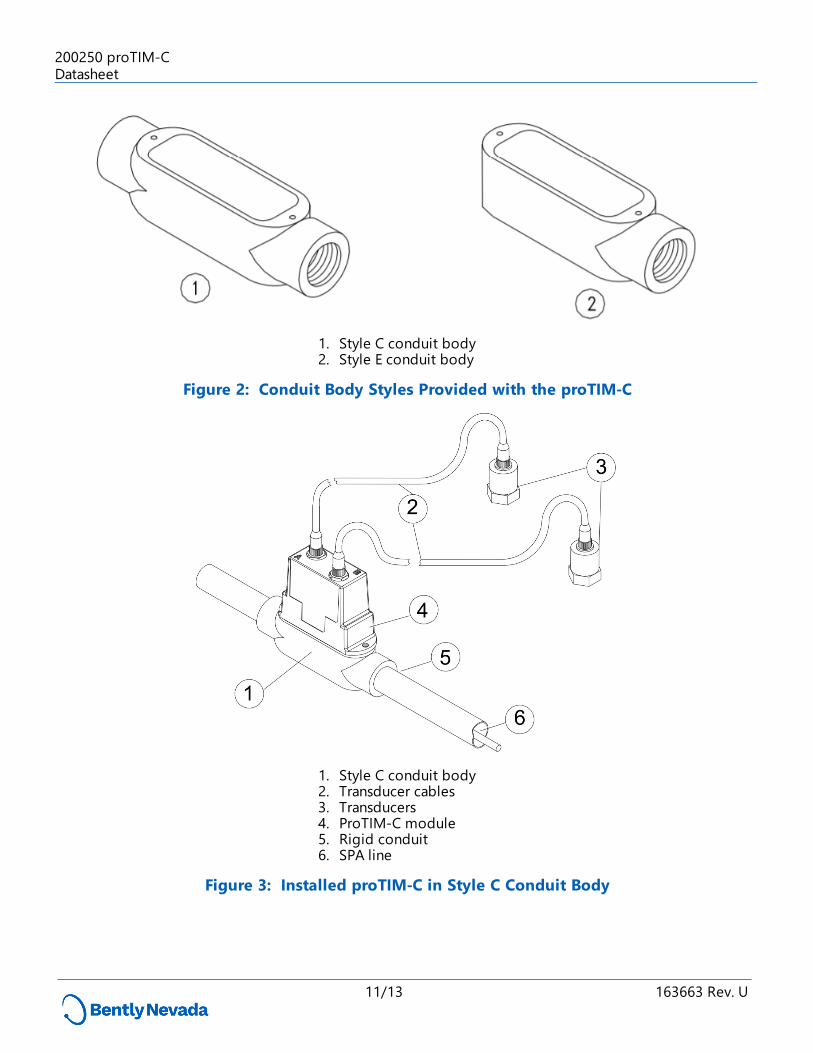
1. Style C conduit body 2. Style E conduit body
Figure 2: Conduit Body Styles Provided with the proTIM-C
1. Style C conduit body 2. Transducer cables 3. Transducers 4. ProTIM-C module 5. Rigid conduit 6. SPA line
Figure 3: Installed proTIM-C in Style C Conduit Body
11/13 163663 Rev. U
200250 proTIM-CDatasheet

1. Retention nuts (2 places) 2. Reinforcing plate 3. Gasket 4. proTIM-C module
Figure 4: Installed proTIM-C Module with Weatherproof Housing
12/13 163663 Rev. U
200250 proTIM-CDatasheet

Copyright 2019 Baker Hughes, a GE company, LLC ("BHGE") All rights reserved.
Bently Nevada, Orbit Logo and Keyphasor are registered trademarks of BHGE in the United States and other countries. All product and company names are trademarks of their respective holders. Use of the
trademarks does not imply any affiliation with or endorsement by the respective holders. This product may be covered by one or more patents, see Bently.com/legal for current status.
The information contained in this document is subject to change without prior notice.1631 Bently Parkway South, Minden, Nevada USA 89423
Phone: 1.775.782.3611 Bently.com
13/13 163663 Rev. U
200250 proTIM-CDatasheet