Embed Size (px)
Citation preview

2002-03 1
TE01-TE02 DLDS Elements
BINP-KEK

2002-03 2

2002-03 3

2002-03 4
Main parameters of TE01-TE02 DLDS
• Number of modes 2
• Operating modes TE01,TE02
• Main waveguide diameter 120 mm
• Node-to-node distance 56.3 m
• TE01 loss -0.001dB/m
• TE02 loss (measured) -0.004dB/m
• Average main waveguide loss of 4-node DLDS 3.5%

2002-03 5
56.3 m
56.3 m
56.3 m
8 Klystrons75 MW, 120 Hz
Beam direction
Circular Waveguide (Ø 120 mm)
Tap-off System
TE 01 - TE 02
Mode Launcher600 MW, 800 ns
TE 02 Mode Extractor
RF Structure, 85 MW, 70 Mv/m
TE 02 Mode Extractor
Super Hybrid
6 m
TE01 - TE02 2x2 DLDS system

2002-03 6
Basic Elements of TE01-TE02 DLDS
• H-Hybrid
• TE10-TE01 Converter
• TE01-TE02 Launcher
• TE01-TE02 Extractor
• 1:1 Power Splitter
• 1:2 Power Splitter
• 90o TE01 Bend
• Phase Shifter

2002-03 7
H-Hybrid. HFSS calculations.
S11
GHz
11.2 11.3 11.4 11.5 11.6 11.7
VS
WR
1.0
1.1
1.2
1.3
1.4
1.5
S13, S14
GHz
11.2 11.3 11.4 11.5 11.6 11.7
Tra
ns
mis
sio
n,
dB
-4.0
-3.5
-3.0
-2.5
-2.0

2002-03 8
H-Hybrid. High Power Model

2002-03 9
11 11.2 11.4 11.6 11.8 121
1.1
1.2
1.3
1.4
Frequency (GHz)
Por
t #1
VS
WR
1.1
1.2
11.424
11 11.2 11.4 11.6 11.8 124
3.5
3
2.5
2
transmission between port #1 and #2 (S12)transmission between port #1 and #4 (S14)
Frequency (GHz)
Tra
nsm
issi
on (
dB)
3
11.424
H-Hybrid. Low power RF test results
Hybrid port # 1 VSWR (S11) Transmission between ports 1 – 2 (S12) and 1 – 4 (S14)

2002-03 10
TE10-TE01 Mode Converter
Output diameter 46 mmLength 280 mm

2002-03 11
TE10-TE01 Mode Converter. HFSS Calculations
S11
GHz
11.2 11.3 11.4 11.5 11.6 11.7
VS
WR
1.00
1.05
1.10
1.15
1.20
1.25
1.30
S12
GHz
11.2 11.3 11.4 11.5 11.6 11.7
S1
2,
dB
-0.5
-0.4
-0.3
-0.2
-0.1
0.0

2002-03 12
TE10-TE01 Mode Converter. Low Power Model

2002-03 13
11.2 11.3 11.4 11.5 11.6 11.71
1.05
1.1
1.15
1.2
1.25
1.3
Frequency (GHz)
VS
WR
1.1
1.2
11.424
11.2 11.3 11.4 11.5 11.6 11.70.8
0.6
0.4
0.2
0
0.2
0 degrees45 degrees90 degrees
Frequency (GHz)
Tra
nsm
issi
on (
dB)
11.424
TE10-TE01 Mode Converter. Low power RF test results
SWR for the TE01 Mode ConverterTransmission from the choke-type TE01 converter
(Ø40mm circular waveguide) to the tested TE01 converter (Ø46mm circular waveguide) for tree angles between H-
plane of the WR90 inputs of these converters

2002-03 14
TE01-TE02 Mode Launcher TE02 Mode Extractor

2002-03 15
TE01-TE02 Launcher-Extractor. HFSS calculations.

2002-03 16
TE01-TE02 Mode Launcher
TE02 Mode Extractor

2002-03 17
Emax = 480kV/cm for 600MW
TE01-TE02 Mode Launcher-Extractor. HFSS calculations.

2002-03 18
Part of TE01-TE02 Launcher-Extractor

2002-03 19
TE01-TE02 Mode Launcher-Extractor. Low Power RF Model

2002-03 20
TE01-TE02 Mode Launcher-Extractor plus Overmoded Tapers.
2002-03 21
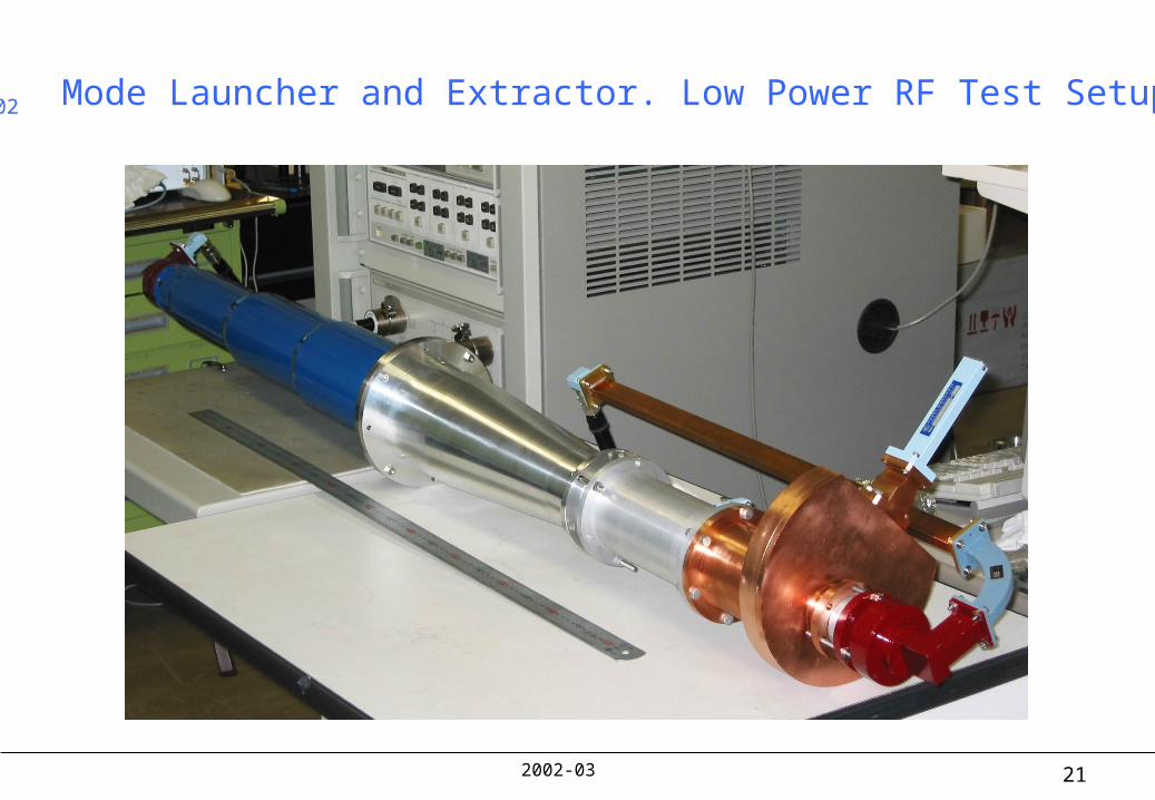
TE02 Mode Launcher and Extractor. Low Power RF Test Setup.
2002-03 22
11.2 11.3 11.4 11.5 11.6 11.71
1.1
1.2
1.3
1.4
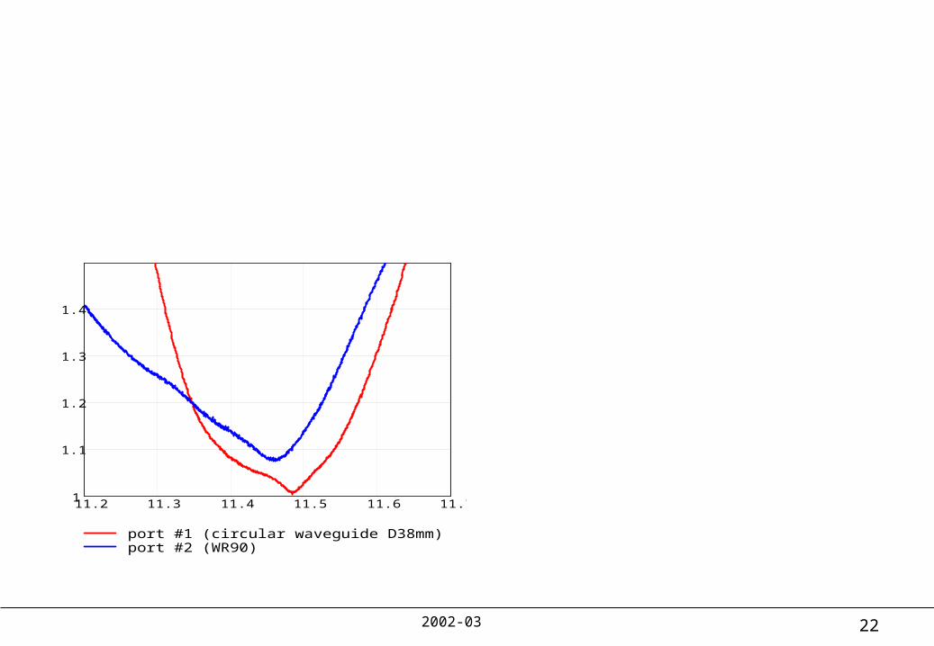
port #1 (circular waveguide D38mm)port #2 (WR90)
Frequency (GHz)
VS
WR
1.1
1.2
11.424
11.2 11.3 11.4 11.5 11.6 11.71
1.1
1.2
1.3
1.4
port #1 (circular waveguide D38mm)port #2 (WR90)
Frequency (GHz)
VS
WR
1.1
1.2
11.424
VSWR of the TE01-TE02 Launcher VSWR of the TE02 Mode Extractor
TE01-TE02 Mode Launcher-Extractor. Low power RF test results.

2002-03 23
11.2 11.3 11.4 11.5 11.6 11.730
28
26
24
22
20
Frequency (GHz)
Tra
nsm
issi
on (
dB
)
11.424
11.2 11.3 11.4 11.5 11.6 11.730
28
26
24
22
20
Frequency (GHz)
Tra
nsm
issi
on (
dB
)
11.424
TE01-TE02 Mode Launcher-Extractor. Low power RF test results.
Isolation between port #1 and port #2 for the TE01-TE02 Launcher
Isolation between port #1 and port #2 for the TE02 Mode Extractor

2002-03 24
Transmitted TE01 Mode Power
GHz
11.30 11.35 11.40 11.45 11.50 11.55 11.60
Tra
ns
mit
ted
Po
we
r, %
90
92
94
96
98
100
Extracted TE02 Mode Power
GHz
11.30 11.35 11.40 11.45 11.50 11.55 11.60
Ex
tra
cte
d P
ow
er,
%
90
92
94
96
98
100
TE02 Mode Extractor. Low power RF test results.
2002-03 25
11.2 11.3 11.4 11.5 11.6 11.75
4.5
4
3.5
3
2.5
2
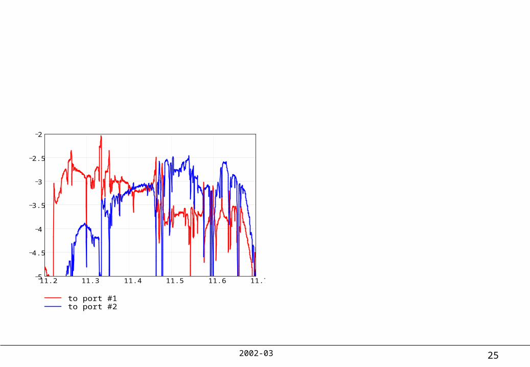
to port #1to port #2
Frequency (GHz)
Tra
nsm
issi
on (
dB) 3
11.424
11.2 11.3 11.4 11.5 11.6 11.75
4.5
4
3.5
3
2.5
2
to port #1to port #2
Frequency (GHz)
Tra
nsm
issi
on (
dB
) 3
11.424
TE01-TE02 Mode Launcher-Extractor. Low power RF test results.
Transmission from the TE01-TE02 Launcher port #1 to the TE02 Extractor port #1 and port #2
Transmission from the TE01-TE02 Launcher port #2 to the TE02 Extractor port #1 and port #2

2002-03 26
1/2 TE01 Power Splitter. HFSS Calculations.

2002-03 27
1/2 TE01 Power Splitter. Low Power RF Model.

2002-03 28
11.2 11.3 11.4 11.5 11.61
1.1
1.2
1.3
1.4
Frequency (GHz)
VS
WR
1.1
1.2
11.424
1/2 TE01 Power Splitter. Low Power RF Test Results.
SWR of the ½ TE01 Power Splitter

2002-03 29
11.2 11.3 11.4 11.5 11.6 11.70.3
0.35
0.4
0.45
0.5
0.55
0.6
0.65
0 degree60 degree
Frequency (GHz)
S12
0.5
11.424
11.2 11.3 11.4 11.5 11.6 11.70.3
0.35
0.4
0.45
0.5
0.55
0.6
0.65
0 degree60 degree
Frequency (GHz)
S13
0.5
11.424
1/2 TE01 Power Splitter. Low Power RF Test Results.
Squared transmission coefficient S12 for the TE01 1/2 Power Splitter for two angles between
H-plane of WR90 input of the TE01 converter and WR90 output #2 of the tested splitter.
Squared transmission coefficient S12 for the TE01 1/2 Power Splitter for two angles between
H-plane of WR90 input of the TE01 converter and WR90 output #3 of the tested splitter.

2002-03 30
1/3 TE01 Power Splitter. HFSS Calculations
S33
GHz
11.2 11.3 11.4 11.5 11.6 11.7
VS
WR
1.0
1.1
1.2
1.3
1.4
1.5
S31, S32
GHz
11.2 11.3 11.4 11.5 11.6 11.7
Sp
litt
ed
Po
we
r, %
0
10
20
30
40
50
60
70
80
90
100

2002-03 31
1/3 TE01 Power Splitter. Low Power RF Model.

2002-03 32
11.2 11.3 11.4 11.5 11.61
1.1
1.2
1.3
1.4
Frequency (GHz)
VS
WR
1.1
1.2
11.424
1/3 TE01 Power Splitter. Low Power RF Test Results.
SWR of the 1/3 TE01 Power Splitter

2002-03 33
11.2 11.3 11.4 11.5 11.6 11.70.2
0.25
0.3
0.35
0.4
0.45
0 degree90 degree
Frequency (GHz)
S1
2
1
3
11.424
11.2 11.3 11.4 11.5 11.6 11.70.5
0.55
0.6
0.65
0.7
0.75
0 degree90 degree
Frequency (GHz)
S13
2
3
11.424
1/3 TE01 Power Splitter. Low Power RF Test Results.
Squared transmission coefficient S12 for the TE01 1/3 Power Splitter for two angles between
H-plane of WR90 input of the TE01 converter and WR90 output #2 of the tested splitter.
Squared transmission coefficient S12 for the TE01 1/3 Power Splitter for two angles between
H-plane of WR90 input of the TE01 converter and WR90 output #3 of the tested splitter.

2002-03 34
90o TE01 Bend. HFSS Calculations.
R=91
49

2002-03 35
90o TE01 Bend. Low Power RF Model.

2002-03 36
11.30 11.35 11.40 11.45 11.50 11.55 11.6099.50
99.55
99.60
99.65
99.70
99.75
99.80
99.85
99.90
99.95
100.00
TE01
- mode purity at the output of 90-degree Bend
Tra
smit
ted
Pow
er,
[ %
]
Frequency, [ GHz ] 11.30 11.35 11.40 11.45 11.50 11.55 11.60
0.0
0.1
0.2
0.3
0.4
0.5
Undesirable modes composition at the output ofTE
01 90-degree Bend
Tra
smit
ted
Pow
er,
[ %
]
Frequency, [ GHz ]
- TE11
mode - TE
21 mode
- TE31
mode
90o TE01 Bend. Low Power RF Test Results.

2002-03 37
Quasi-pulse measurement with long pipe
The measurements of propagation of pure TE01 and TE02 modes.
Measurements layout:
2002-03 38
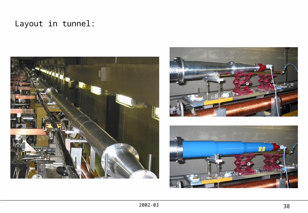
Layout in tunnel:

2002-03 39
Result of measurements:
Tapers + Line + Short
ns
-100 0 100 200 300 400 500 600 700 800 900 1000
Am
pl
0.0
0.1
0.2
0.3
0.4
0.5
0.6
0.7
0.8
0.9
1.0
1.1
InputTE01_line_shortTE02_line_short
TE01 one-way efficiency 98.54%TE02 one-way efficiency 95.20%
Loss:TE01 - 1.46% (theory 1.18% )
TE02 - 5.75% (theory 4.31%)

2002-03 40
Measurements of TE01-TE02 Launcher-Extractor performances

2002-03 41
‘No long pipe’ setup:

2002-03 42
TE01 output
GHz
11.374 11.399 11.424 11.449 11.474
TE
01
po
rt,
po
we
r
0.0
0.1
0.2
0.3
0.4
0.5
0.6
0.7
0.8
0.9
1.0
Phase 0O
Phase 180O
TE02 output
GHz
11.374 11.399 11.424 11.449 11.474
TE
02
po
rt,
po
we
r
0.0
0.1
0.2
0.3
0.4
0.5
0.6
0.7
0.8
0.9
1.0
Phase 0O
Phase 180O
Measured efficiency of launching and extraction of TE01 mode 97.1%
Measured efficiency of launching and extraction of TE02 mode 97%
Theoretical estimated efficiency 97%
Results of measurements

2002-03 43
Measurements with long pipe.

2002-03 44
Obtained results are discrepant. The reasons are not clear enough. One of them can be low quality of backward WR90 waveguide. Measurements are going to be repeated in end of June.
As preliminary results can be taken ones from the measurements of below setup:

2002-03 45
Results of measurements:
TE01_Taper + D1_extr.
ns
-100 0 100 200 300 400 500 600 700 800 900 1000
Am
p.
0.0
0.1
0.2
0.3
0.4
0.5
0.6
0.7
0.8
0.9
1.0
1.1
InputPort1 - load, Port2 - loadPort1 - short, Port2 -loadPort1 - load, Port2 - short
TE02_Taper + D1_extr.
ns
-100 0 100 200 300 400 500 600 700 800 900 1000
Am
pl
0.0
0.1
0.2
0.3
0.4
0.5
0.6
0.7
0.8
0.9
1.0
1.1
InputPort1 - load, Port2 - loadPort1 - load, Port2 - shortPort1 - short, Port2 - load
TE01_Taper + D2_extr.
ns
-100 0 100 200 300 400 500 600 700 800 900 1000
Am
p.
0.0
0.1
0.2
0.3
0.4
0.5
0.6
0.7
0.8
0.9
1.0
1.1
InputPort1 - load, Port2 - loadPort1 - short, Port2 -load
TE02_Taper + D2_extr.
ns
-100 0 100 200 300 400 500 600 700 800 900 1000
Am
pl
0.0
0.1
0.2
0.3
0.4
0.5
0.6
0.7
0.8
0.9
1.0
1.1
InputPort1 - load, Port2 - loadPort1 - load, Port2 - shortPort1 - short, Port2 - load
Device1; Efficiency of TE01 extr. 98.7 Device1; Efficiency of TE02 extr. 97.7
Device2; Efficiency of TE01 extr. 96.9 Device2; Efficiency of TE02 extr. 98.8

2002-03 46
Average efficiency of TE01 extraction 97.8%Average efficiency of TE02 extraction 98.2%
We can expect the efficiency of 2-mode DLDS (loss in pipe not included) ~ 96%