Embed Size (px)
Citation preview
P. Michael Henderson, [email protected] 1
Introduction to Optical Networks
P. Michael [email protected]
9/13/2014
P. Michael Henderson, [email protected] 2
Agenda The physics of light Laser and photodetector operation Characteristics of optical fiber Optical amplifiers SONET First generation networks Second generation networks Digital wrappers Summary
9/13/2014
P. Michael Henderson, [email protected] 3
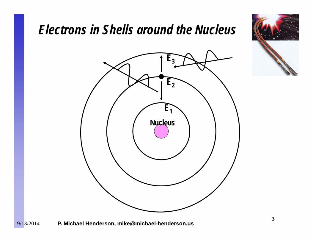
E1
E2
E3
Nucleus
Electrons in Shells around the Nucleus
9/13/2014
P. Michael Henderson, [email protected] 4
E2
E1
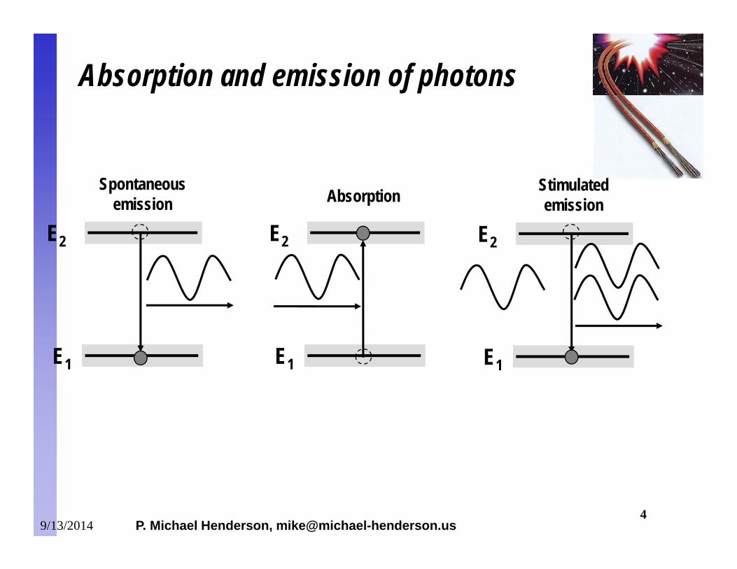
Absorption
Absorption and emission of photons
E2
E1
Spontaneousemission
E2
E1
Stimulatedemission
9/13/2014
P. Michael Henderson, [email protected] 5
E2
E1
Energy
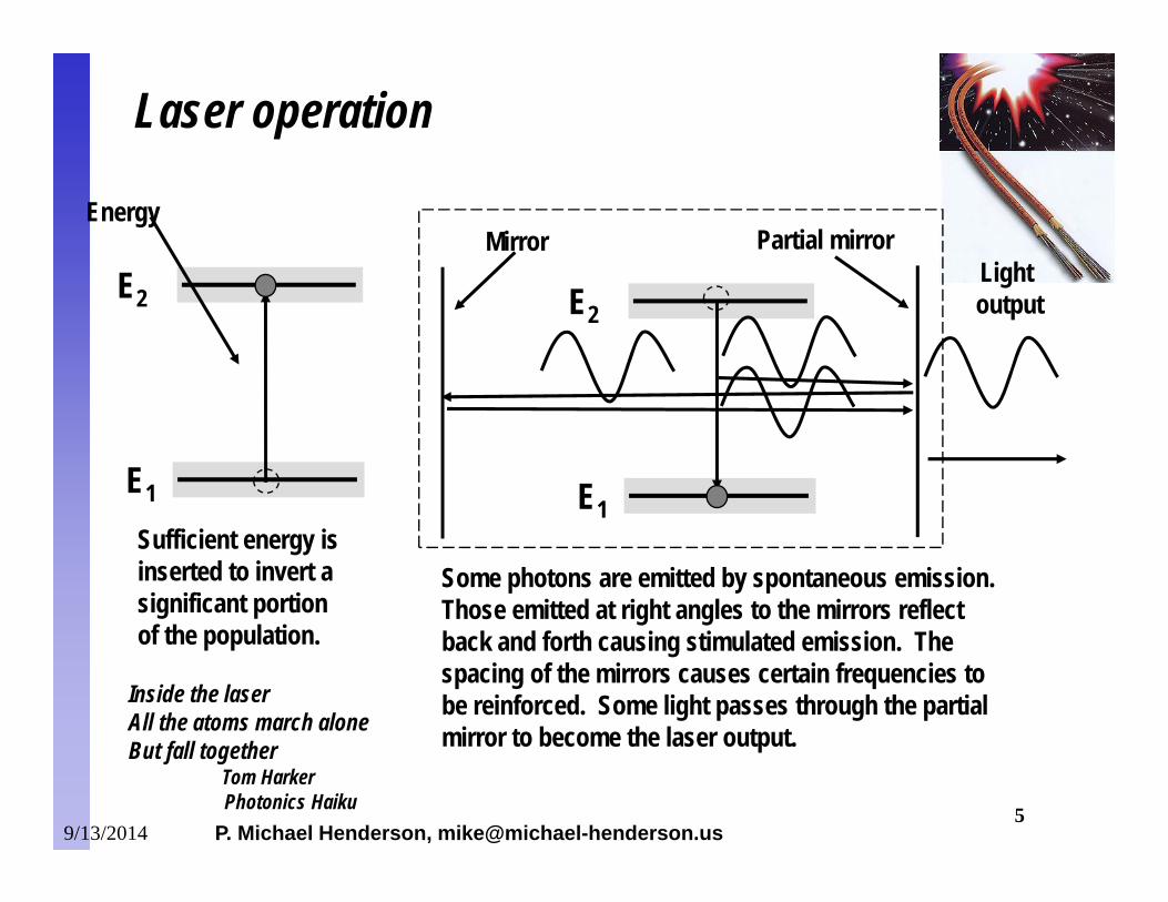
Laser operation
E2
E1
Some photons are emitted by spontaneous emission. Those emitted at right angles to the mirrors reflect back and forth causing stimulated emission. The spacing of the mirrors causes certain frequencies to be reinforced. Some light passes through the partial mirror to become the laser output.
Sufficient energy isinserted to invert a significant portion of the population.
Mirror Partial mirrorLight output
Inside the laserAll the atoms march aloneBut fall together
Tom Harker Photonics Haiku
9/13/2014
P. Michael Henderson, [email protected] 6
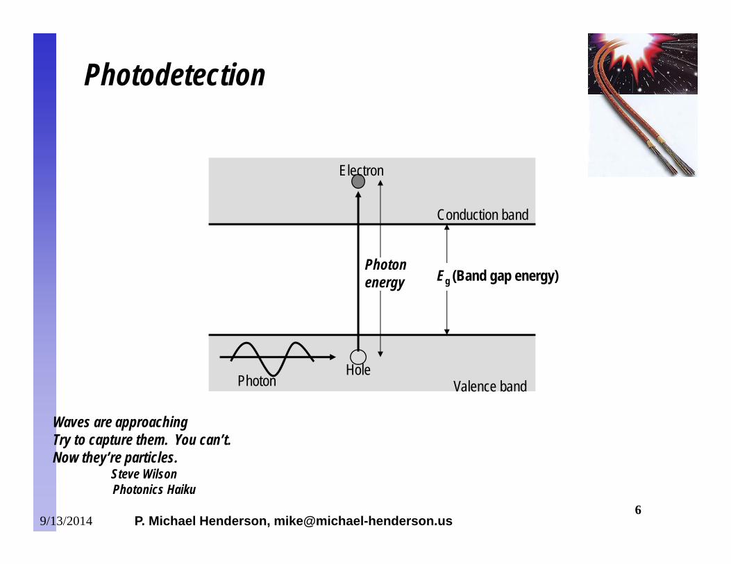
PhotonHole
Electron
Valence band
Conduction band
Eg (Band gap energy)Photonenergy
Photodetection
Waves are approachingTry to capture them. You can’t.Now they’re particles.
Steve Wilson Photonics Haiku
9/13/2014
P. Michael Henderson, [email protected] 7
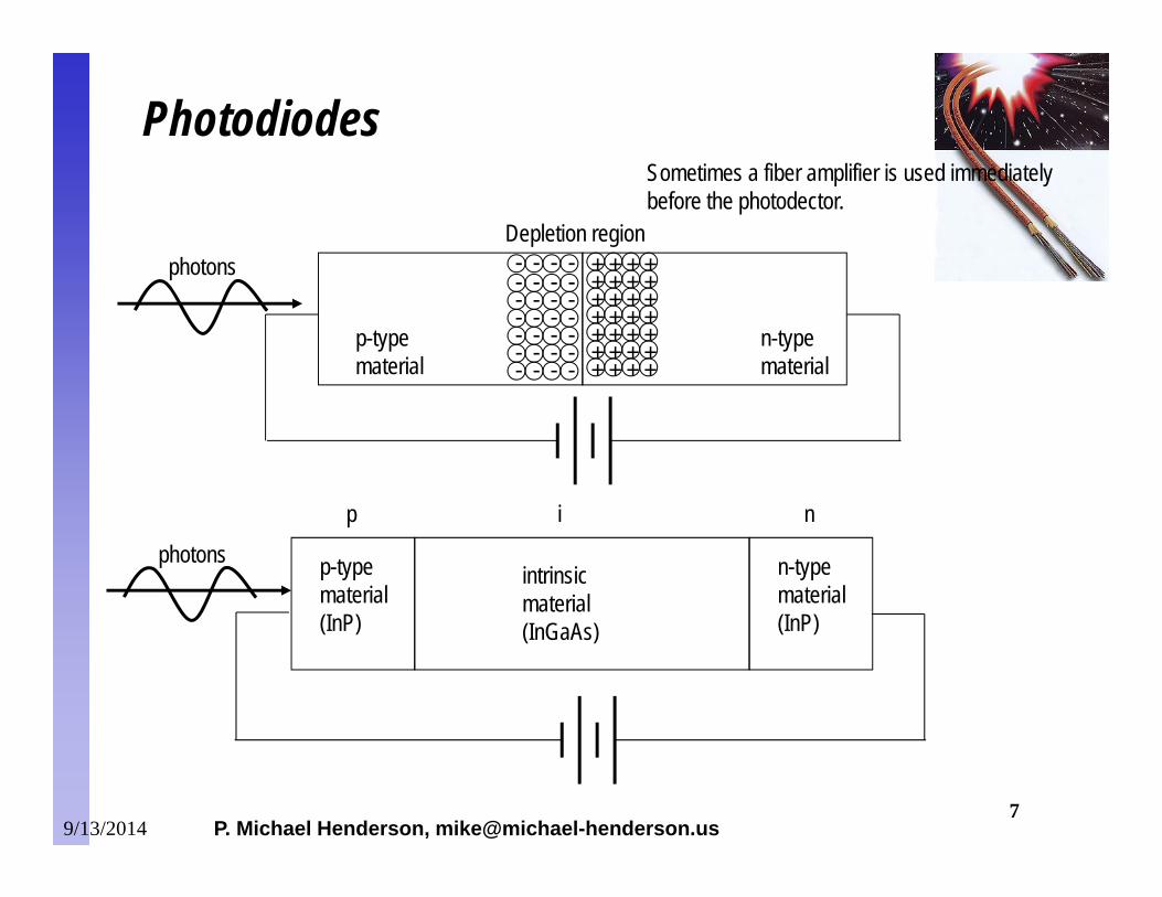
p-typematerial
Depletion region
+
++++++
+++++++
+
++++++
+++++++
--
--
---
-------
-------
-------
n-typematerial
Photodiodes
p-typematerial(InP)
n-typematerial(InP)
intrinsicmaterial(InGaAs)
p i n
photons
photons
Sometimes a fiber amplifier is used immediately before the photodector.
9/13/2014
P. Michael Henderson, [email protected] 8
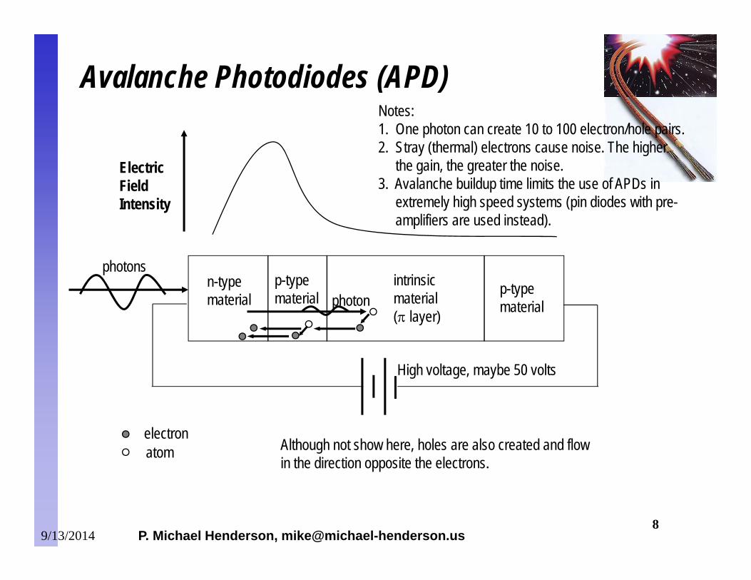
Avalanche Photodiodes (APD)
n-typematerial
p-typematerial
intrinsicmaterial( layer)
photonsp-typematerial
Electric Field Intensity
photon
electronatom Although not show here, holes are also created and flow
in the direction opposite the electrons.
High voltage, maybe 50 volts
Notes:1. One photon can create 10 to 100 electron/hole pairs.2. Stray (thermal) electrons cause noise. The higher
the gain, the greater the noise.3. Avalanche buildup time limits the use of APDs in
extremely high speed systems (pin diodes with pre-amplifiers are used instead).
9/13/2014
P. Michael Henderson, [email protected] 9
Lasers can be modulated either directly or externally.– Direct modulation is done by controlling the electrical drive to
the laser.– External modulation is done by controlling a “shutter” which
sits between the laser output and the fiber. The laser operates continuously. Most common is lithium niobate.
Direct modulation is less expensive but causes “chirp” in the output. (Chirp = a change in the frequency of the light over the pulse time).– Chirped pulses have much worse dispersion characteristics
and thus are distance limited. Lasers in the backbone network are externally modulated.
Modulation of Lasers
9/13/2014
P. Michael Henderson, [email protected] 11
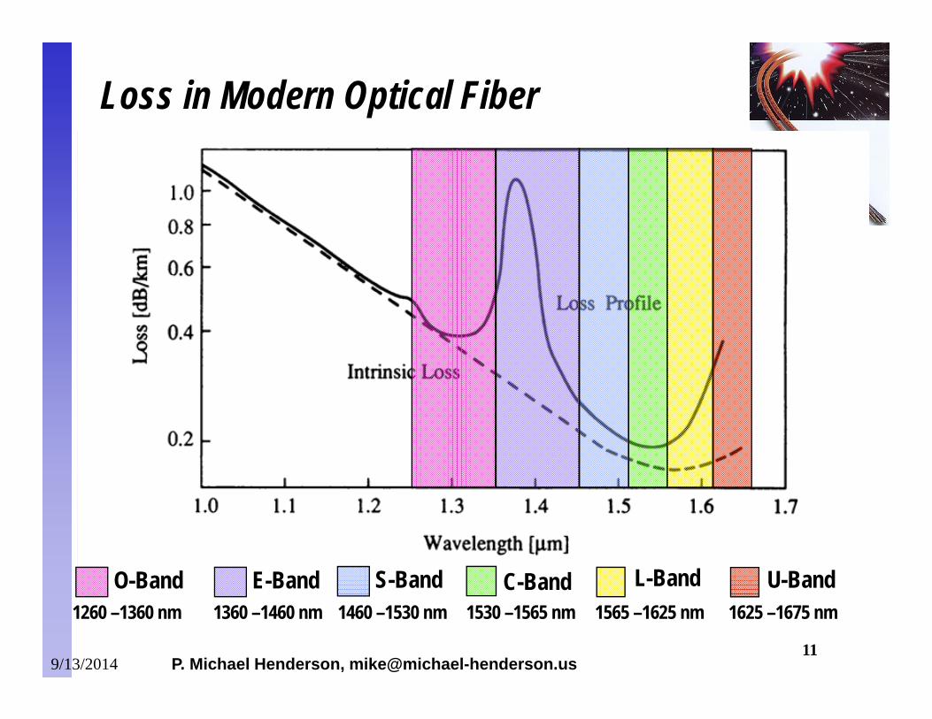
S-Band C-Band L-Band U-BandE-BandO-Band1260 –1360 nm 1360 –1460 nm 1460 –1530 nm 1530 –1565 nm 1565 –1625 nm 1625 –1675 nm
Loss in Modern Optical Fiber
9/13/2014
P. Michael Henderson, [email protected] 12
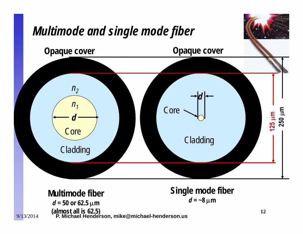
d
n2
n1
Core
Cladding
Opaque cover
Cladding
Opaque cover
d
Multimode fiberd = 50 or 62.5 m(almost all is 62.5)
Core
Single mode fiberd = ~8 m
Multimode and single mode fiber
9/13/2014
P. Michael Henderson, [email protected] 13
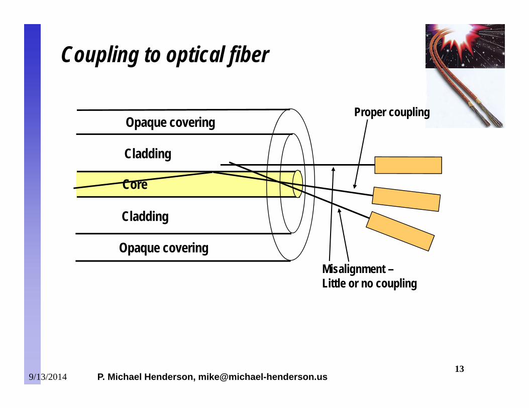
Coupling to optical fiber
Misalignment –Little or no coupling
Proper couplingOpaque covering
Opaque covering
Cladding
Cladding
Core
9/13/2014
P. Michael Henderson, [email protected] 14
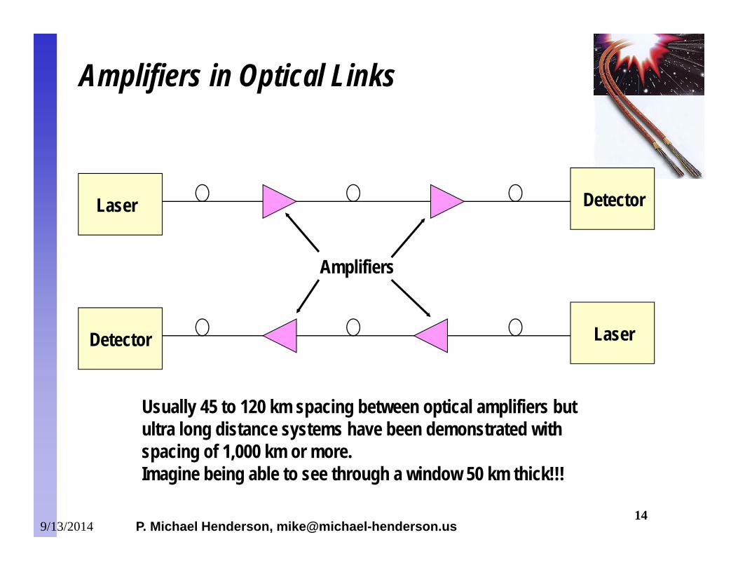
Amplifiers
DetectorLaser
LaserDetector
Amplifiers in Optical Links
Usually 45 to 120 km spacing between optical amplifiers but ultra long distance systems have been demonstrated with spacing of 1,000 km or more. Imagine being able to see through a window 50 km thick!!!
9/13/2014
P. Michael Henderson, [email protected] 15
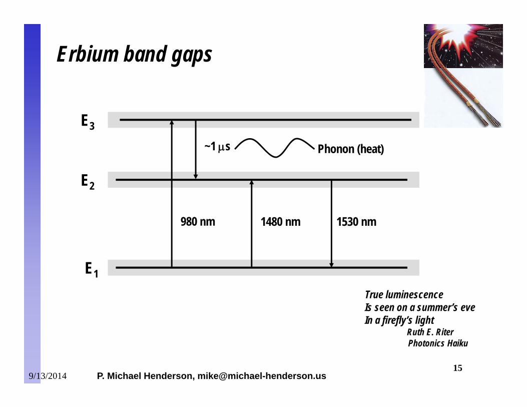
E3
E2
E1
980 nm 1480 nm 1530 nm
Erbium band gaps
~1 s Phonon (heat)
True luminescenceIs seen on a summer’s eveIn a firefly’s light
Ruth E. Riter Photonics Haiku
9/13/2014

P. Michael Henderson, [email protected] 16
Exploits an effect known as “stimulated Raman scattering.”– When two signals in a fiber are within a certain frequency of each other,
energy is transferred from the higher frequency signal to the lower frequency signal.
Raman amplifiers exploit this effect by injecting a wavelength a certain frequency above the wavelength to be amplified.– Usually done in the “reverse” direction by injecting the wavelength
towards the laser.– Can be done at Erbium amplifier locations.
Used in combination with Erbium amplifiers to create cascaded amplifiers. This produces better noise figures.
Raman Amplifiers
9/13/2014
P. Michael Henderson, [email protected] 17
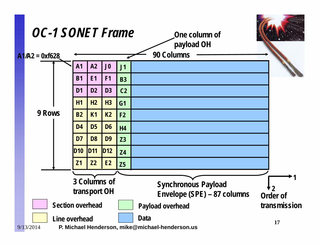
9 Rows
90 Columns
3 Columns oftransport OH
A1 A2 J0
B1 E1 F1
D1 D2 D3
H1 H2 H3
B2 K1 K2
D4 D5 D6
D7 D8 D9
D10 D11 D12
Z1 Z2 E2
J1
B3C2
G1
F2
H4Z3
Z4
Z5
Section overhead
Line overhead
Payload overhead
A1/A2 = 0xf628
Data
OC-1 SONET Frame One column ofpayload OH
Synchronous Payload Envelope (SPE) – 87 columns
12
Order oftransmission
9/13/2014
P. Michael Henderson, [email protected] 18
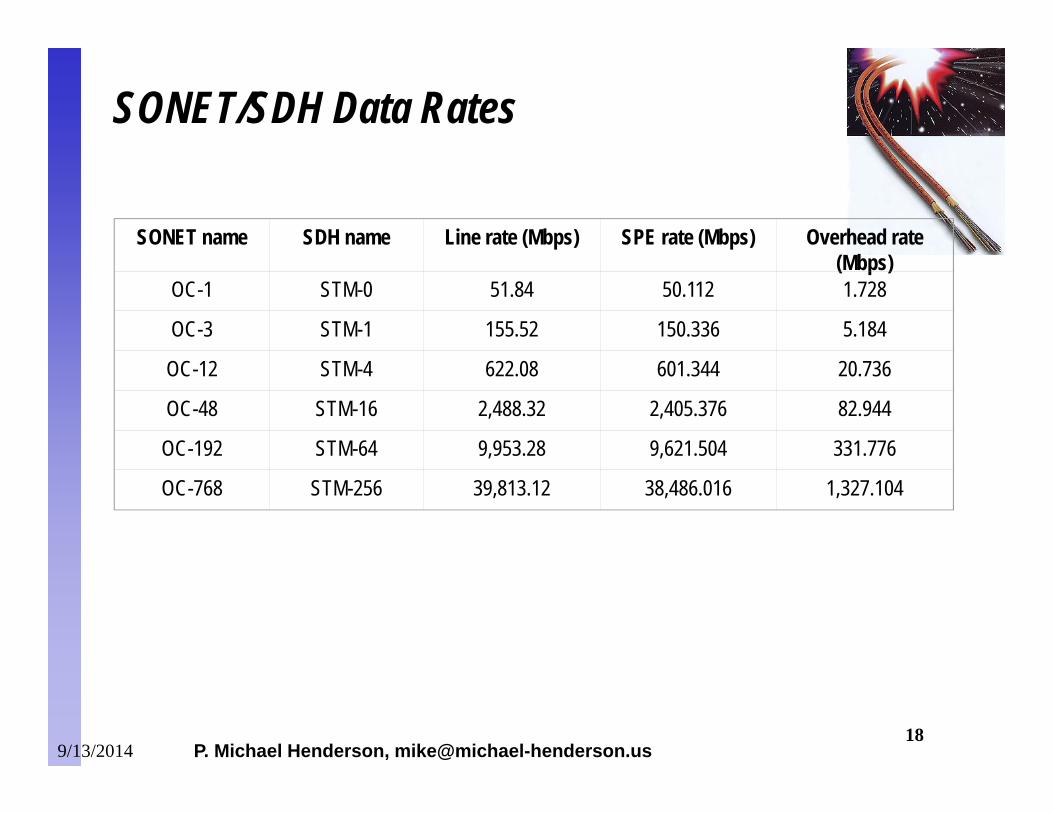
SONET name SDH name Line rate (Mbps) SPE rate (Mbps) Overhead rate (Mbps)
OC-1 STM-0 51.84 50.112 1.728
OC-3 STM-1 155.52 150.336 5.184
OC-12 STM-4 622.08 601.344 20.736
OC-48 STM-16 2,488.32 2,405.376 82.944
OC-192 STM-64 9,953.28 9,621.504 331.776
OC-768 STM-256 39,813.12 38,486.016 1,327.104
SONET/SDH Data Rates
9/13/2014
P. Michael Henderson, [email protected] 19
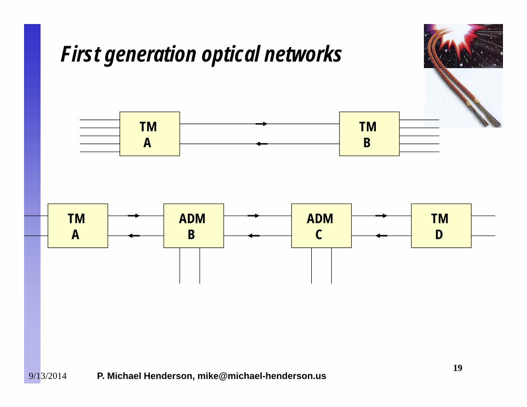
TMA
TMB
ADMC
TMD
TMA
ADMB
First generation optical networks
9/13/2014
P. Michael Henderson, [email protected] 20
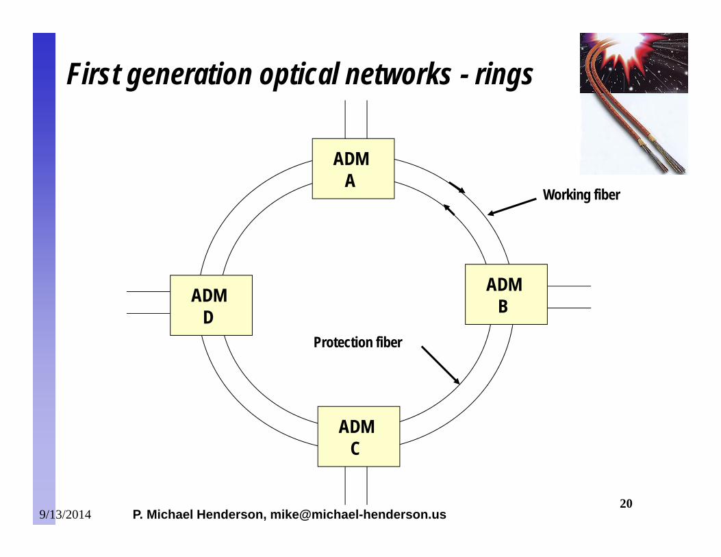
ADMA
ADMB
ADMC
ADMD
Working fiber
Protection fiber
First generation optical networks - rings
9/13/2014
P. Michael Henderson, [email protected] 21
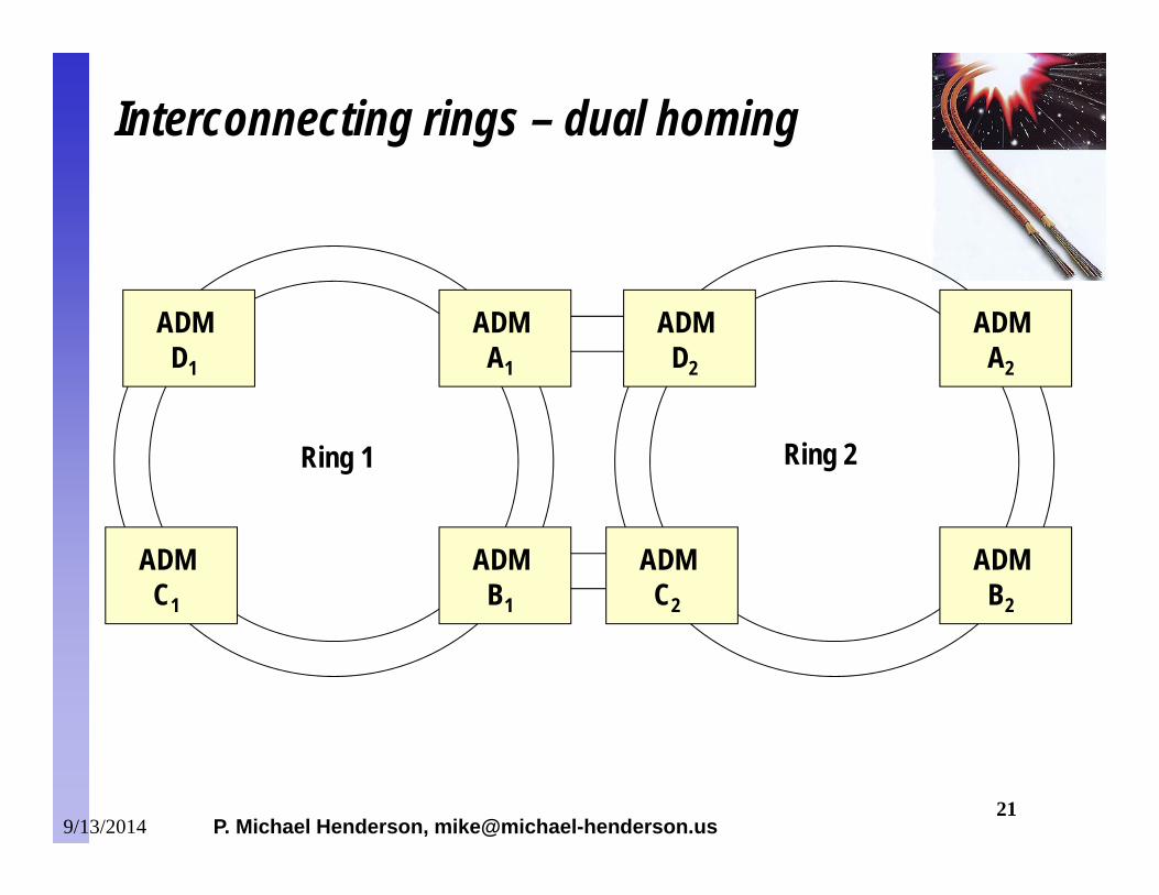
ADMA1
ADMB1
ADMC1
ADMD1
ADMA2
ADMB2
ADMC2
ADMD2
Ring 1 Ring 2
Interconnecting rings – dual homing
9/13/2014
P. Michael Henderson, [email protected] 22
SONET is designed to carry TDM voice, not data.– The frame time for SONET/SDH is 125 s, no matter what the
line rate. Some technique is required to frame and transport data,
especially IP traffic.– Some techniques used are frame relay, asynchronous transfer
mode (ATM) and packet over SONET (POS).
ATM and Packet over SONET
9/13/2014
P. Michael Henderson, [email protected] 23
ATM was designed to carry both voice and data.– Connection oriented system, with quality of service (QoS) defined.
ATM adaptation layers (AAL) are used to frame traffic.– AAL5 used for data, such as IP.– AAL1 and AAL2 used for voice.
In general, network providers are moving away from ATM in the backbone.– ATM adds an additional network layer which adds cost for equipment
and must be managed.– The overhead for protocol conversion to AALx limits the performance
of the system. ATM cannot operate at the highest optical rates.
ATM
9/13/2014
P. Michael Henderson, [email protected] 24
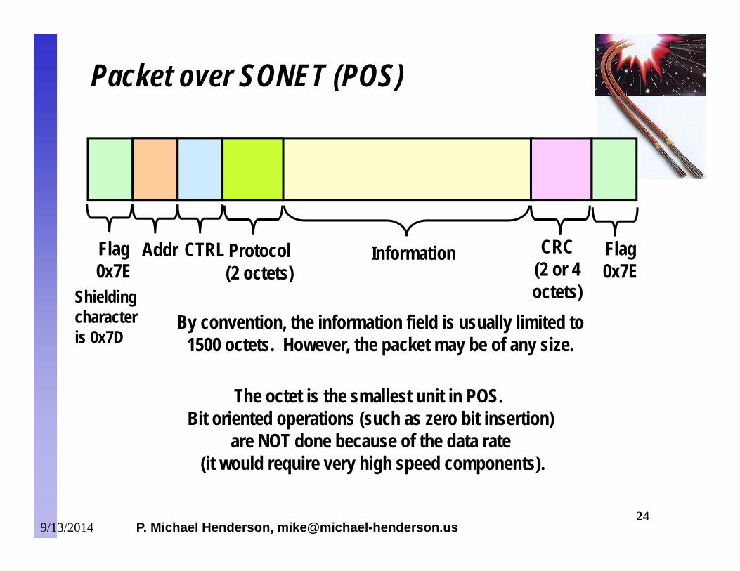
By convention, the information field is usually limited to 1500 octets. However, the packet may be of any size.
Packet over SONET (POS)
InformationFlag0x7E
Flag0x7E
CRC(2 or 4octets)
Addr CTRL Protocol(2 octets)
The octet is the smallest unit in POS. Bit oriented operations (such as zero bit insertion)
are NOT done because of the data rate (it would require very high speed components).
Shielding characteris 0x7D
9/13/2014
P. Michael Henderson, [email protected] 25
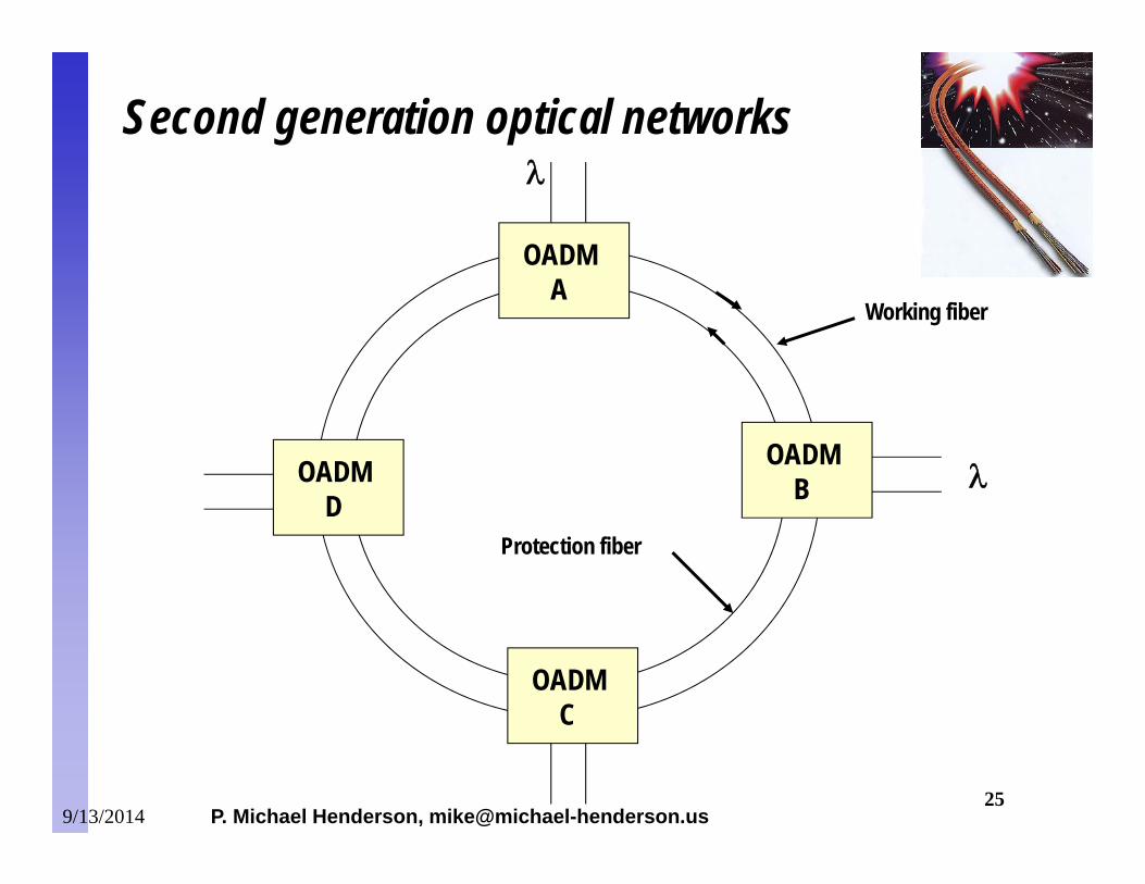
OADMA
OADMB
OADMC
OADMD
Working fiber
Protection fiber
Second generation optical networks
9/13/2014
P. Michael Henderson, [email protected] 26
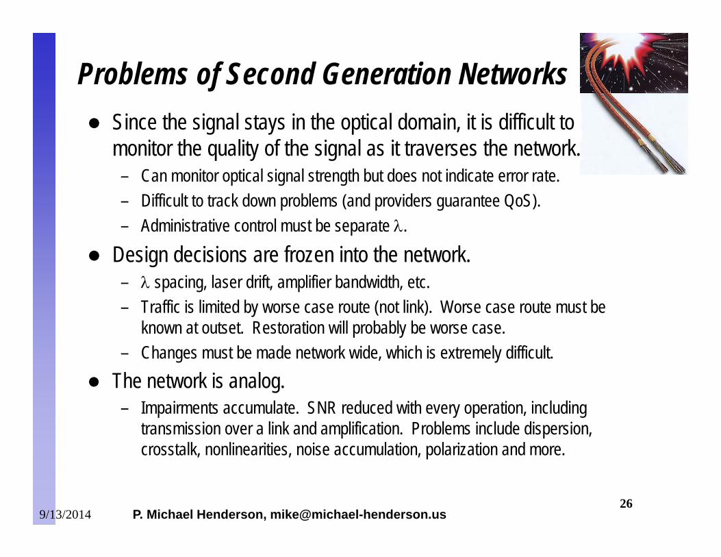
Since the signal stays in the optical domain, it is difficult to monitor the quality of the signal as it traverses the network.
– Can monitor optical signal strength but does not indicate error rate.– Difficult to track down problems (and providers guarantee QoS).– Administrative control must be separate .
Design decisions are frozen into the network.– spacing, laser drift, amplifier bandwidth, etc.– Traffic is limited by worse case route (not link). Worse case route must be
known at outset. Restoration will probably be worse case.– Changes must be made network wide, which is extremely difficult.
The network is analog.– Impairments accumulate. SNR reduced with every operation, including
transmission over a link and amplification. Problems include dispersion, crosstalk, nonlinearities, noise accumulation, polarization and more.
Problems of Second Generation Networks
9/13/2014
P. Michael Henderson, [email protected] 27
SONET in-band.– For OC-48 and up.– Does a BCH code on the payload data in each row.– Redundant bits located in overhead columns of same or next row.– Provides error correction while maintaining line rates.– Only works for SONET/SDH
Digital wrapper.– Takes octets and adds redundant octets for correction.– Uses Reed Solomon (255,239) code.– One octet of data area used for overhead.– Handles any type of payload – SONET, Ethernet, etc.– Increases line rate by about 15/14.– More on digital wrapper in next few slides.
Forward Error Correction in Optical Networks
9/13/2014
P. Michael Henderson, [email protected] 28
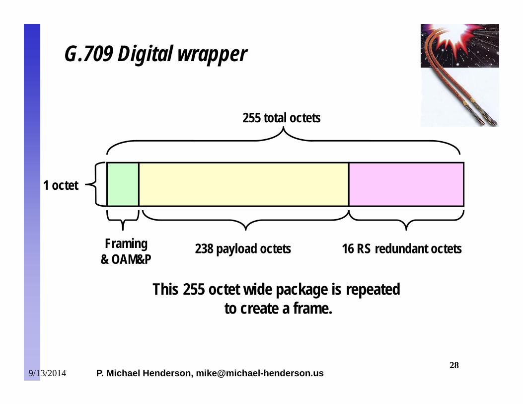
238 payload octets 16 RS redundant octetsFraming& OAM&P
255 total octets
1 octet
This 255 octet wide package is repeated to create a frame.
G.709 Digital wrapper
9/13/2014
P. Michael Henderson, [email protected] 29
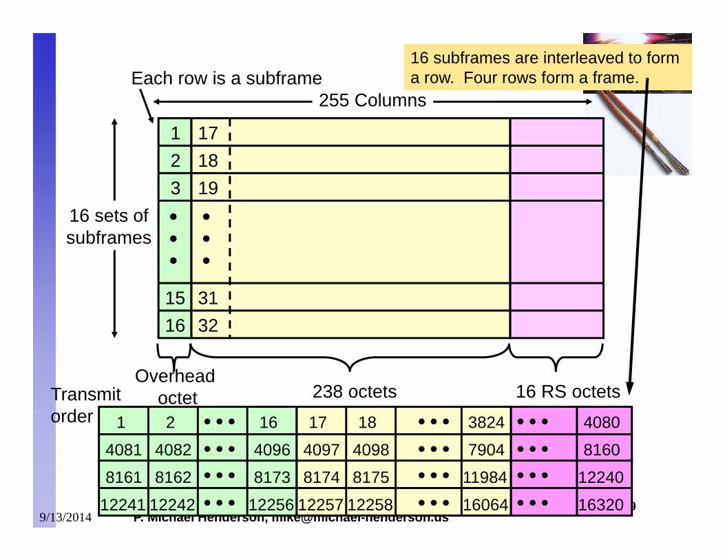
16 sets ofsubframes
255 Columns
238 octets 16 RS octetsOverhead
octet
123
16
171819
32
15 31
1 2 16 17 18 3824
Transmitorder
Each row is a subframe
4081 4082 4096 7904
4080
8160 4097 4098
8161 8162 8173 8174 8175 11984
12241 12242 12256 16064
12240
16320 12257 12258
16 subframes are interleaved to form a row. Four rows form a frame.
9/13/2014
P. Michael Henderson, [email protected] 30
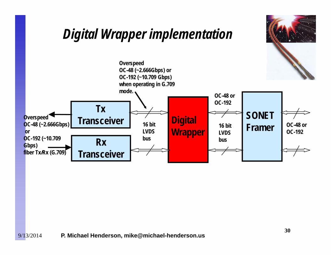
SONETFramer
DigitalWrapper
TxTransceiver
OC-48 orOC-192
OverspeedOC-48 (~2.666Gbps)or
OC-192 (~10.709 Gbps) fiber Tx/Rx (G.709)
OverspeedOC-48 (~2.666Gbps) orOC-192 (~10.709 Gbps)when operating in G.709mode.
OC-48 orOC-192
16 bit LVDSbus
16 bit LVDSbusRx
Transceiver
Digital Wrapper implementation
9/13/2014
P. Michael Henderson, [email protected] 31
Volume expected to be very large, probably more than 10 times the size of the backbone network.
Must be significantly lower cost than backbone network. Wavelength division multiplexing will almost certainly be
used.– Cost to lay fiber in metropolitan areas is too high.– May use coarse WDM for lower cost.
Gigabit and 10 Gigabit Ethernet likely to play a major role.– Ethernet components are simple and low cost.– Logical extension of the corporate LAN.
Metropolitan/Access Area Network
9/13/2014
P. Michael Henderson, [email protected] 32
There’s a lot more to optical networks than described here.– This presentation only skimmed the surface.
The network is moving towards all-optical technology. Still lots of electronic technology required, both at the
edge and inside the network. Metropolitan and Access networks will be a major
growth area for the future, requiring high volume and low cost.
Summary
9/13/2014


![Cable Based Networks.ppt [Read-Only]](https://img.pdfslide.us/doc/110x75/616a1f3b11a7b741a34f0ac3/cable-based-read-only.jpg)