Embed Size (px)
Citation preview

Introduction After the introduction of affordable LiFePO4, LTO and Li‐ion batteries, off‐grid solutions became feasible. It is vital that such batteries are charged very carefully. In other words, they can easily be over‐charged, or over‐ discharged. Cell temperature and current are also very important, in order to guarantee a long life. The 123\SmartBMS (Battery Management System) is primarily intended for prismatic cells, but can also be adapted by the end‐user for other cell shapes, provided the cell voltage is in the working voltage range of 1.5 – 5 volt.
Package contents The standard 4 cells/12V package contains:
1x Begin Cell Board 1x End Cell Board 2x Between Cell Boards 2x Dual range current sensors 20A/500A Piece of 0.75 mm² wire for the interconnections
Connector unlock tool
Specifications All specifications measured at 3.3V cell voltage and zero ampere through current sensors.
Description Value / range
General specifications
Operating voltage range 1.5V to 5.0V
Operating temperature range ‐40 to 85°C
Voltage measurement accuracy ± 20mV
Temperature measurement accuracy ± 2°C
Balancing current 1A
Number of Cells 2 to 255
Board type dependent specifications
“Between” module current average <1.0mA
Begin Board current average with 1 current sensor <1.1mA
Begin Board current average with 2 current sensors <1.6mA
End Board current average with standby Bluetooth <1.6mA
End Boards current average when device connected to Bluetooth <11.0mA
Maximum current through charge / load signal relays on End Board 2A @ 30VDC 1A @ 60VDC
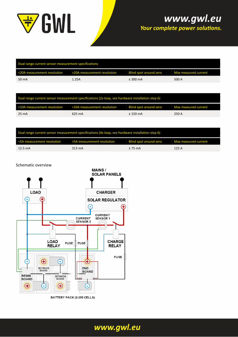
Dual range current sensor measurement specifications
<20A measurement resolution >20A measurement resolution Blind spot around zero Max measured current
50 mA 1.25A ± 300 mA 500 A
Dual range current sensor measurement specifications (2x loop, see hardware installation step 6)
<10A measurement resolution >10A measurement resolution Blind spot around zero Max measured current
25 mA 625 mA ± 150 mA 250 A
Dual range current sensor measurement specifications (4x loop, see hardware installation step 6)
<5A measurement resolution >5A measurement resolution Blind spot around zero Max measured current
12.5 mA 313 mA ± 75 mA 125 A
Schematic overview

Hardware installation Please be aware that your battery pack contains a large amount of energy, which can be potentially dangerous. Use isolated spanners to prevent any short circuits. High inrush currents, causing arcing (sparks) and ultra‐high electromagnetic levels, can easily damage electronic circuits. We therefore strongly recommend to always FIRST connect the so called "large current connections" in a new setup, and THEN separately connect the BMS boards.
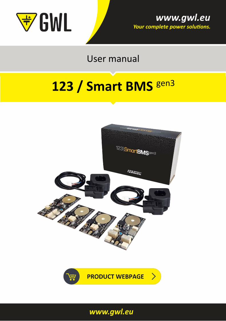
STEP 1
Prepare the BMS boards by soldering a wire on the battery minus solder pad (marked ‐ ) Place a cable lug on the other end of the cable to make a connection to the minus pole of the battery. Please use at least wire of 0.75 mm2 to prevent a voltage drop. If the positive (+) hole on the cell module is too small, you can make this hole bigger with a drill. Make sure to remove the drilling dust afterwards to prevent short circuits or other unintended behaviour.
STEP 2
Prepare the battery pack. A good way of doing this is indicated on step 2 image. Start cleaning the cell poles, the copper strips and cable lugs with sanding paper. Use threaded rods instead of normal bolts. Don't forget to also attach wires to the first and last cell in the same way, and connect these to the solar panels, MPPT, charger and the load.
STEP 3
Mount the cell boards on the battery pack. Make sure the Begin Board is mounted on the minus side of the total battery pack. This is the cell where the big (black) minus cable leaves the battery pack. Make sure the End Board is mounted on the plus side of the battery pack. This is the cell where the big (red) plus cable leaves the battery pack.
STEP 4/5
After the Begin Board is connected correctly, the LED will start blinking every second. This shows the Begin Board is trying to send out data to the following cell board. Start making the interconnection of the Begin Board to the following cell board. Make a connection from the connector marked “OUT” on the Begin Board to the connector marked “IN” on the following cell board. It doesn’t matter which hole of the 2 pin connector you pick. Please be careful while you’re doing this, prevent short circuits. After you have made the interconnection between the Begin Board and the first cell board you will notice the green LED on the cell board will flash as well every second. This confirms the cell board is correctly installed and the interconnection between the Boards are made correct. Now go on with the other cell boards. Make connections from the double connector marked “OUT” to the next cell board connector marked “IN”. Be careful when inserting the cable, do not use excessive force. When the flashing LEDs stop somewhere in the middle of the cell chain, there is an error, in this case check the wiring.
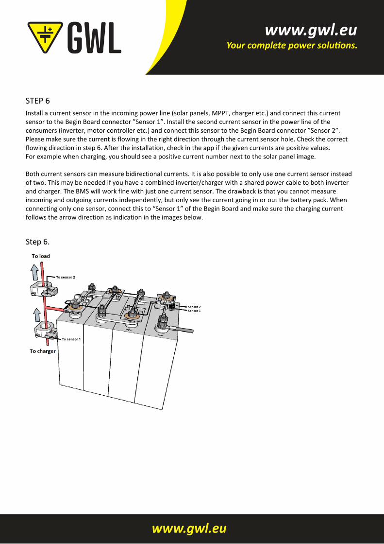
STEP 6
Install a current sensor in the incoming power line (solar panels, MPPT, charger etc.) and connect this current sensor to the Begin Board connector ”Sensor 1”. Install the second current sensor in the power line of the consumers (inverter, motor controller etc.) and connect this sensor to the Begin Board connector ”Sensor 2”. Please make sure the current is flowing in the right direction through the current sensor hole. Check the correct flowing direction in step 6. After the installation, check in the app if the given currents are positive values. For example when charging, you should see a positive current number next to the solar panel image. Both current sensors can measure bidirectional currents. It is also possible to only use one current sensor instead of two. This may be needed if you have a combined inverter/charger with a shared power cable to both inverter and charger. The BMS will work fine with just one current sensor. The drawback is that you cannot measure incoming and outgoing currents independently, but only see the current going in or out the battery pack. When connecting only one sensor, connect this to “Sensor 1” of the Begin Board and make sure the charging current follows the arrow direction as indication in the images below.
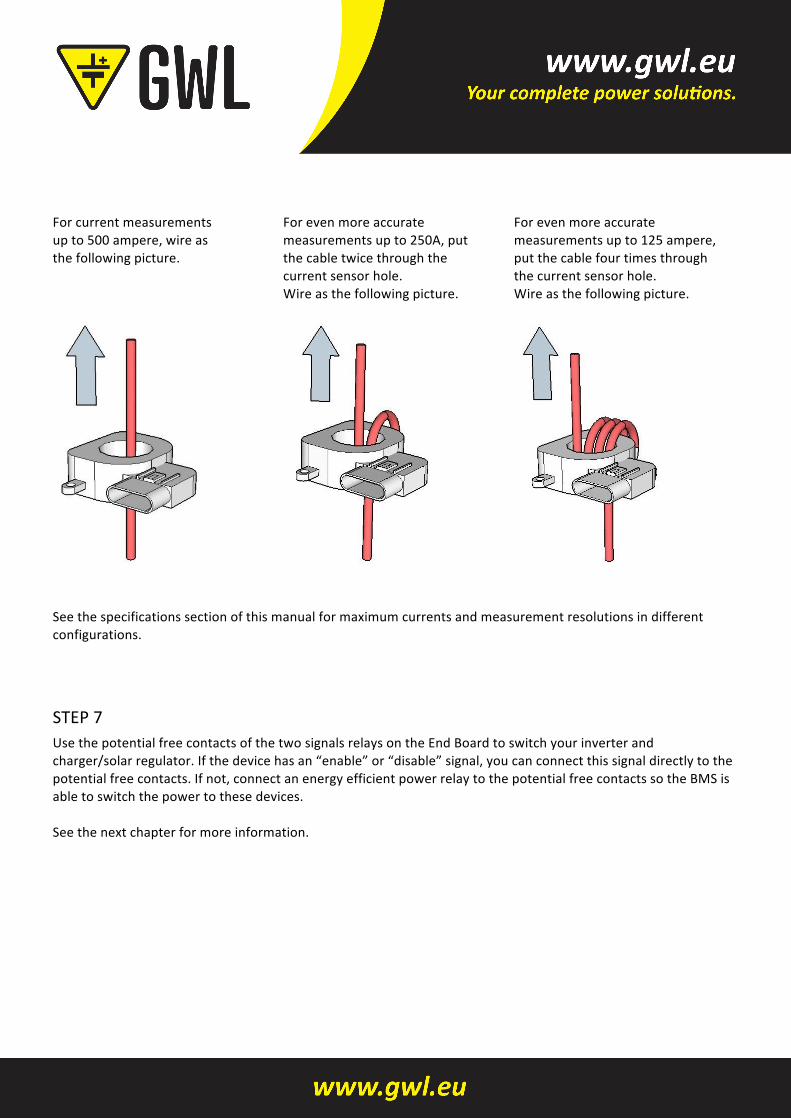
Forcurrentmeasurementsupto500ampere,wireasthefollowingpicture.
Forevenmoreaccuratemeasurementsupto250A,putthecabletwicethroughthecurrentsensorhole.Wireasthefollowingpicture.
Forevenmoreaccuratemeasurementsupto125ampere,putthecablefourtimesthroughthecurrentsensorhole.Wireasthefollowingpicture.
Seethespecificationssectionofthismanualformaximumcurrentsandmeasurementresolutionsindifferentconfigurations.
STEP7UsethepotentialfreecontactsofthetwosignalsrelaysontheEndBoardtoswitchyourinverterandcharger/solarregulator.Ifthedevicehasan“enable”or“disable”signal,youcanconnectthissignaldirectlytothepotentialfreecontacts.Ifnot,connectanenergyefficientpowerrelaytothepotentialfreecontactssotheBMSisabletoswitchthepowertothesedevices.Seethenextchapterformoreinformation.
Controlling external Components The End Board contains two signal relays with three potential free contacts (normally open, common contact, normally closed) to control external components of your off‐grid system. This can be “solar chargers”, “Maximum power point trackers”, “inverters”, etc. An example is the “enable” pin on many inverters. Otherwise you can connect an energy efficient power relay which can control the battery power supply to the charger/inverter. The maximum current through the signal relays is specified in section “Specifications”.
CHARGE RELAY
There is one relay to control incoming energy components of the system, like MPPT, solar charger et. This relay is called the “CHARGE” relay. When charging is allowed the green CHARGE LED next to the CHARGE relay will flash every second. When charging is allowed Pin 1 and 2 of the CHARGE relay contacts (see End Board details) are closed (pin 2 & 3 are open). When charging is NOT allowed Pin 2 and 3 of the CHARGE relay contacts are closed (pin 1 & 2 are open). Note: when switching inductive loads like a relay/contactor, make sure there is a protection against flyback of the coil. A simple example is the flyback diode parallel to the coil.
LOAD RELAY
The other relay is to control outgoing energy components of the system, like inverters or other consumers. This relay is called the “LOAD” relay. When discharging is allowed the green LOAD LED next to the LOAD relay will flash every second. Note: when switching inductive loads like a relay/contactor, make sure there is a protection against flyback of the coil. A simple example is the flyback diode parallel to the coil. The 123\SmartRelay, Victron BatteryProtect and Kilovac EV200 relays do not need a separate flyback protection.
Hardware setting
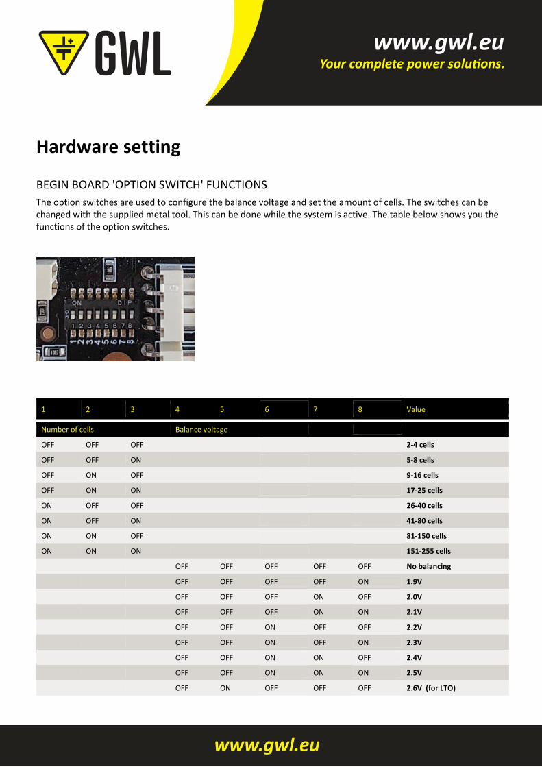
BEGIN BOARD 'OPTION SWITCH' FUNCTIONS
The option switches are used to configure the balance voltage and set the amount of cells. The switches can be changed with the supplied metal tool. This can be done while the system is active. The table below shows you the functions of the option switches.
1 2 3 4 5 6 7 8 Value
Number of cells Balance voltage
OFF OFF OFF 2‐4 cells
OFF OFF ON 5‐8 cells
OFF ON OFF 9‐16 cells
OFF ON ON 17‐25 cells
ON OFF OFF 26‐40 cells
ON OFF ON 41‐80 cells
ON ON OFF 81‐150 cells
ON ON ON 151‐255 cells
OFF OFF OFF OFF OFF No balancing
OFF OFF OFF OFF ON 1.9V
OFF OFF OFF ON OFF 2.0V
OFF OFF OFF ON ON 2.1V
OFF OFF ON OFF OFF 2.2V
OFF OFF ON OFF ON 2.3V
OFF OFF ON ON OFF 2.4V
OFF OFF ON ON ON 2.5V
OFF ON OFF OFF OFF 2.6V (for LTO)
1 2 3 4 5 6 7 8 Value
Number of cells Balance voltage
OFF ON OFF OFF ON 2.7V
OFF ON OFF ON OFF 2.8V
OFF ON OFF ON ON 2.9V
OFF ON ON OFF OFF 3.0V
OFF ON ON OFF ON 3.1V
OFF ON ON ON OFF 3.2V
OFF ON ON ON ON 3.3V
ON OFF OFF OFF OFF 3.4V (for LiFe4PO)
ON OFF OFF OFF ON 3.5V
ON OFF OFF ON OFF 3.6V
ON OFF OFF ON ON 3.7V
ON OFF ON OFF OFF 3.8V
ON OFF ON OFF ON 3.9V
ON OFF ON ON OFF 4.0V (for NMC)
ON OFF ON ON ON 4.1V
ON ON OFF OFF OFF 4.2V
ON ON OFF OFF ON 4.3V
ON ON OFF ON OFF 4.4V
ON ON OFF ON ON 4.5V
ON ON ON OFF OFF 4.6V
ON ON ON OFF ON 4.7V
ON ON ON ON OFF 4.8V
ON ON ON ON ON 4.9V
Option switch nr 1 ‐ 3: Please set the number of cells of your battery pack. See table for details. Option switch nr 4 ‐ 8: Set option switch 4 ‐ 8 in the right positions for the balance threshold voltage you like. Above this voltage, the cell board starts balancing. See table for details. For balance voltage explanation read the text below.
Keep the batteries in perfect condition The drawing below shows that your expensive batteries are in safe hands with 123\SmartBMS gen3. To keep batteries in the best condition, it is necessary to constantly monitor the voltage and temperature of individual cells. The voltage should stay within specified limits to prevent damage to the cells. Keeping the batteries in a safe operating temperature also prevents possible damage.
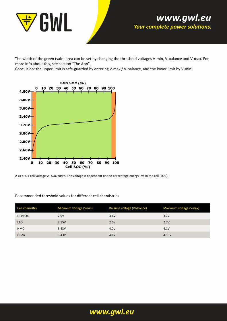
The width of the green (safe) area can be set by changing the threshold voltages V‐min, V‐balance and V‐max. For more info about this, see section “The App”. Conclusion: the upper limit is safe‐guarded by entering V‐max / V‐balance, and the lower limit by V‐min.
A LiFePO4 cell voltage vs. SOC curve. The voltage is dependent on the percentage energy left in the cell (SOC).
Recommended threshold values for different cell chemistries
Cell chemistry Minimum voltage (Vmin) Balance voltage (Vbalance) Maximum voltage (Vmax)
LiFePO4 2.9V 3.4V 3.7V
LTO 2.15V 2.6V 2.7V
NMC 3.43V 4.0V 4.1V
Li‐ion 3.43V 4.1V 4.15V
The App
FIRST CONNECTION
Go to the App store for Apple devices and search for “123SmartBMS”. Install the 123SmartBMS App on your Apple device. For Android devices go to the Play store and search for “123SmartBMS”. Install the App on your Android device. Enable the Bluetooth functionality of your device. Start the App, You will see an overview of an off‐grid system. Tab settings in the right bottom corner to open the settings section. Tap on the discovered 123\SmartBMS device to make a connection. The App will ask for a password, this password is stored in the BMS to prevent anybody with a Bluetooth device can control your BMS. The default password is “1234”. After the connection has been made it’s time to configure the system. To disconnect, tap again on the BMS ID with the checkmark next to it.
APP SETTINGS
Solar peak power: Set the maximum power of your incoming energy source, for example solar panels. If the system contains 10 solar panels of 250 Watt each, the total power of 2.50 kW has to be configured. Inverter peak power: Set the maximum power of the consumers, for example an inverter. When your inverter can supply 5 kilowatt, 5.00 kW has to be configured. Battery capacity: The battery capacity can of course be set to the total capacity of the battery pack. We advise however to take only 80% of the rated capacity, to comply with cell aging and temperature effects. Example: If you use four 200 Ah cells 4 x 200 x 3.2 = 2560 Wh. In this case we advise to use a value of 2560 x 0.8 = 2048 Wh 2.0 kWh. Current sensor: Please set the current sensor type you are using. The standard current sensors supplied in the set are dual range 500A – 20A. Critical mode: Read extra info section B. Change PIN: It is recommended to change the password of the BMS to prevent intruders can sabotage the system. Tab the “change PIN” line and follow the instructions. Clear energy counters: Totals of incoming and outgoing energy will be stored into the BMS. If you like to set these total counters to zero, tab the “Clear energy counters” line and follow the instructions. V min: If one of the cells gets below this minimum cell voltage threshold the “Vl“ warning indicator on the battery details screen is switched on. The “allow to discharge” relay to control external devices will be switched off. V max: If one of the cells gets above this maximum cell voltage threshold the “Vh“ warning indicator on the battery details screen is switched on. The “allow to charge” relay to control external devices will be switched off.

V balance: This is the balancing voltage where you want all the cells to end up. Above this voltage the cell modules start to dissipate 1 ampere to balance the cells. This setting can be changed with the option switches on the Begin Board. T min: If one of the cells gets below this minimum cell temperature threshold the “Tl“ warning indicator on the battery details screen is switched on. Both relays to control external devices will be switched off. T max: If one of the cells gets above this maximum cell temperature threshold the “Th“ warning indicator on the battery details screen is switched on. Both relays to control external devices be switched off. Charge restart: The charge relay switches ON again if the capacity is below the programmable “Charge restart” and the BMS is in “Normal mode”. This is to prevent toggling relays. Discharge restart: The load relay will be switched on again if the capacity is above the programmable “Discharge restart” and the BMS is in “Normal mode”. Prevent auto‐lock: Enabling this function prevent the device goes into sleep mode. Show simulator: If you don’t have an 123\SmartBMS but you like to discover the App, you can run a simulator. Support: You can contact the app developer and give your feedback. The App version will be showed here.
DASHBOARD
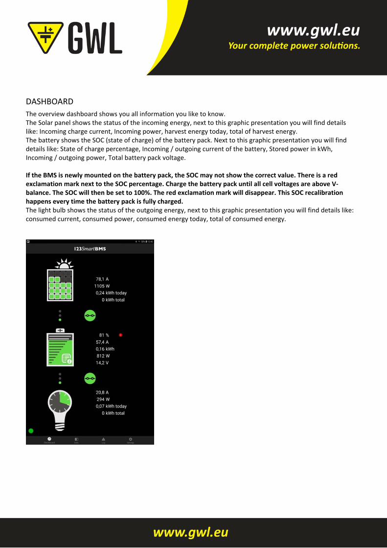
The overview dashboard shows you all information you like to know. The Solar panel shows the status of the incoming energy, next to this graphic presentation you will find details like: Incoming charge current, Incoming power, harvest energy today, total of harvest energy. The battery shows the SOC (state of charge) of the battery pack. Next to this graphic presentation you will find details like: State of charge percentage, Incoming / outgoing current of the battery, Stored power in kWh, Incoming / outgoing power, Total battery pack voltage. If the BMS is newly mounted on the battery pack, the SOC may not show the correct value. There is a red exclamation mark next to the SOC percentage. Charge the battery pack until all cell voltages are above V‐balance. The SOC will then be set to 100%. The red exclamation mark will disappear. This SOC recalibration happens every time the battery pack is fully charged. The light bulb shows the status of the outgoing energy, next to this graphic presentation you will find details like: consumed current, consumed power, consumed energy today, total of consumed energy.
BATTERY DETAILS
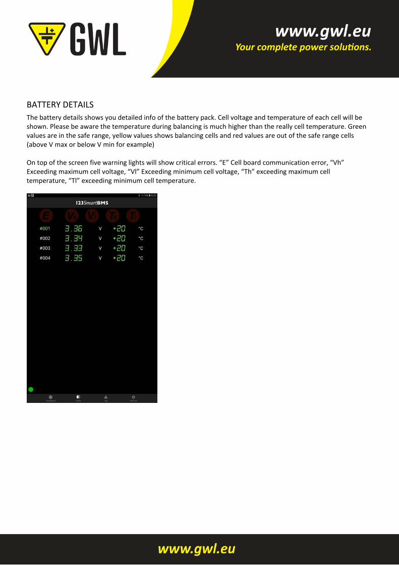
The battery details shows you detailed info of the battery pack. Cell voltage and temperature of each cell will be shown. Please be aware the temperature during balancing is much higher than the really cell temperature. Green values are in the safe range, yellow values shows balancing cells and red values are out of the safe range cells (above V max or below V min for example) On top of the screen five warning lights will show critical errors. “E” Cell board communication error, “Vh” Exceeding maximum cell voltage, “Vl” Exceeding minimum cell voltage, “Th” exceeding maximum cell temperature, “Tl” exceeding minimum cell temperature.
Algorithm
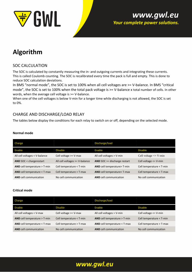
SOC CALCULATION
The SOC is calculated by constantly measuring the in‐ and outgoing currents and integrating these currents. This is called Coulomb counting. The SOC is recalibrated every time the pack is full and empty. This is done to reduce SOC calculation deviations.
In BMS “normal mode”, the SOC is set to 100% when all cell voltages are >= V‐balance. In BMS “critical mode”, the SOC is set to 100% when the total pack voltage is >= V‐balance x total number of cells. In other
words, when the average cell voltage is >= V‐balance. When one of the cell voltages is below V‐min for a longer time while discharging is not allowed, the SOC is set to 0%.
CHARGE AND DISCHARGE/LOAD RELAY
The tables below display the conditions for each relay to switch on or off, depending on the selected mode. Normal mode
Charge Discharge/load
Enable Disable Enable Disable
All cell voltages < V‐balance Cell voltage >= V‐max All cell voltages > V‐min Cell voltage <= V-min
AND SOC < chargerestart All cell voltages >= V‐balance AND SOC >= discharge restart Cell voltage <= V‐min
AND cell temperature > T‐min Cell temperature < T‐min AND cell temperature> T‐min Cell temperature < T‐min
AND cell temperature < T‐max Cell temperature > T‐max AND cell temperature< T‐max Cell temperature > T‐max
AND cell communication No cell communication AND cell communication No cell communication
Critical mode
Charge Discharge/load
Enable Disable Enable Disable
All cell voltages < V‐max Cell voltage >= V‐max All cell voltages > V‐min Cell voltage <= V‐min
AND cell temperature > T‐min Cell temperature < T‐min AND cell temperature > T‐min Cell temperature < T‐min
AND cell temperature < T‐max Cell temperature > T‐max AND cell temperature < T‐max Cell temperature > T‐max
AND cell communication No cell communication AND cell communication No cell communication
Module details
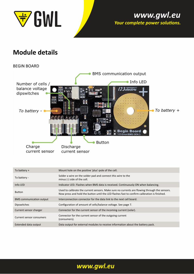
BEGIN BOARD
To battery + Mount hole on the positive 'plus'‐pole of the cell.
To battery ‐ Solder a wire on the solder pad and connect this wire to the minus (‐) side of the cell.
Info LED Indicator LED. Flashes when BMS data is received. Continuously ON when balancing.
Button Used to calibrate the current sensors. Make sure no currents are flowing through the sensors. Now press and hold the button until the LED flashes fast to confirm calibration is finished.
BMS communication output Interconnection connector for the data link to the next cell board.
Dipswitches Configuration of amount of cells/balance voltage. See page 7.
Current sensor charger Connector for the current sensor of the incoming current (solar).
Current sensor consumers Connector for the current sensor of the outgoing current (consumers).
Extended data output Data output for external modules to receive information about the battery pack.
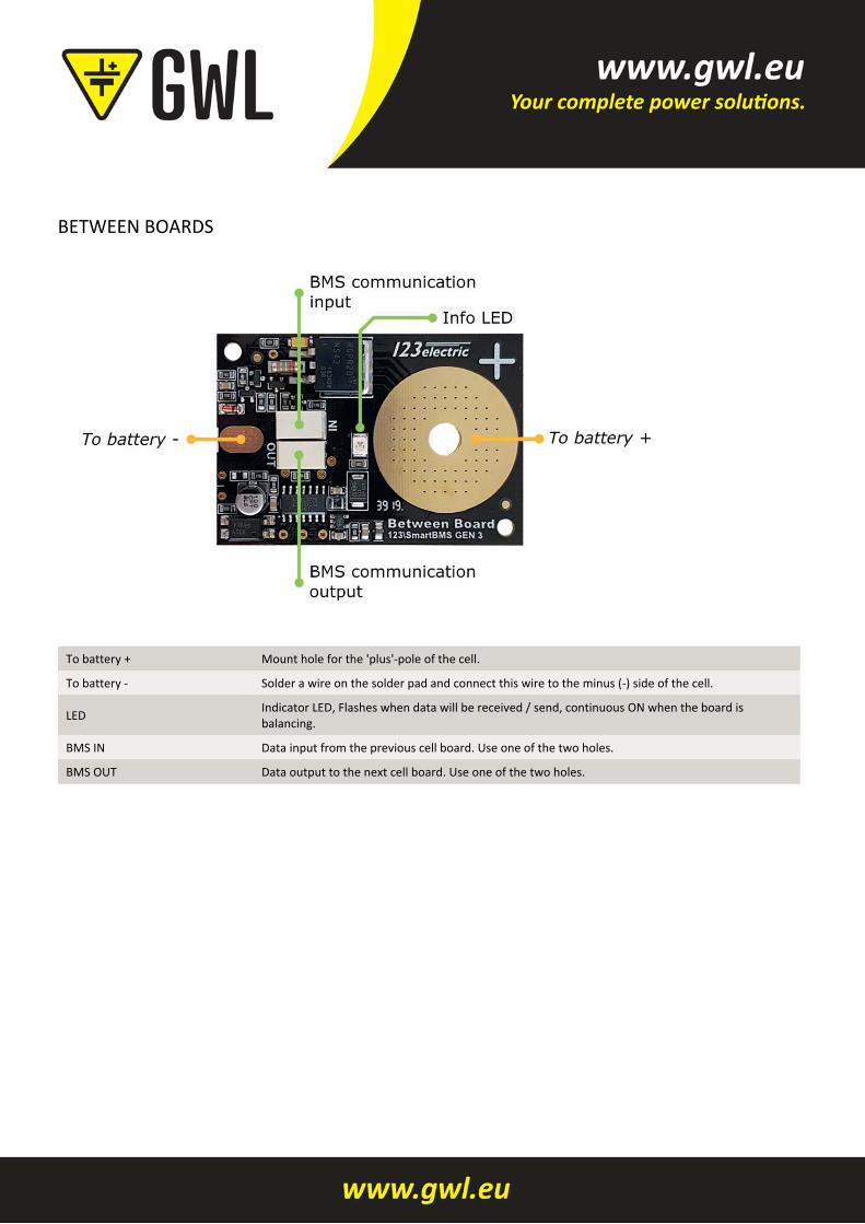
BETWEEN BOARDS
To battery + Mount hole for the 'plus'‐pole of the cell.
To battery ‐ Solder a wire on the solder pad and connect this wire to the minus (‐) side of the cell.
LED Indicator LED, Flashes when data will be received / send, continuous ON when the board is balancing.
BMS IN Data input from the previous cell board. Use one of the two holes.
BMS OUT Data output to the next cell board. Use one of the two holes.
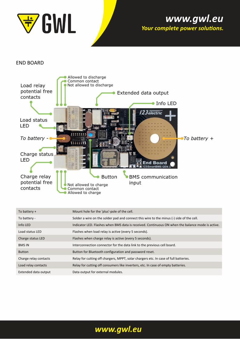
END BOARD
To battery + Mount hole for the 'plus'‐pole of the cell.
To battery ‐ Solder a wire on the solder pad and connect this wire to the minus (‐) side of the cell.
Info LED Indicator LED. Flashes when BMS data is received. Continuous ON when the balance mode is active.
Load status LED Flashes when load relay is active (every 5 seconds).
Charge status LED Flashes when charge relay is active (every 5 seconds).
BMS IN Interconnection connector for the data link to the previous cell board.
Button Button for Bluetooth configuration and password reset.
Charge relay contacts Relay for cutting off chargers, MPPT, solar chargers etc. In case of full batteries.
Load relay contacts Relay for cutting off consumers like inverters, etc. In case of empty batteries.
Extended data output Data output for external modules.

Troubleshooting
NO COMMUNICATION
No battery data on the app and the “E” sign will light ON in the battery details tab of the App. Check the flashing LEDs on the string of cells. The position where the LEDs stop flashing is the location of the problem. Check wiring or replace cell modules to see which of the two is faulty.
FORGOT MY PASSWORD
Press and hold the blue button on the End Board for 5 seconds. The password will be set to the default “1234” and the Bluetooth module will be reconfigured.
BLUETOOTH DOES NOT WORK
Make sure your phone supports Bluetooth 4.0 LE. The following steps can help to connect to the BMS. 1. Restart the App and check in de Settings screen if the BMS appears. 2. Restart your phone and open the App to check again. 3. Try a different phone, download the 123SmartBMS app and check if you see the BMS in the device list. 4. Press and hold the blue button on the End Board for 5 seconds. The password will be set to the factory
default “1234” and the Bluetooth will be reconfigured.
Indicated currents are not zero while no current is being drawn Make sure there is absolutely no current flowing through the current sensors during the zero calibration procedure. On the Begin Board you will find a blue button. Press and hold the blue button until the LED flashes fast several times. Now release the button. The calibration is done.
Appendix
a. Only one current sensor or cable It is possible to only use 1 current sensor, the BMS will also work perfectly fine. Using one sensor will use less power on the Begin Board. The drawback is that you cannot measure incoming and outgoing currents independently, but only see the current going in or out the battery pack. Connect the current sensor to “Sensor 1” on the Begin Board and make sure to see a positive current in the app next to the battery icon when charging and a negative current when discharging.
b. Multiple battery cells or packs parallel There is a difference between placing multiple cells parallel or packs parallel.
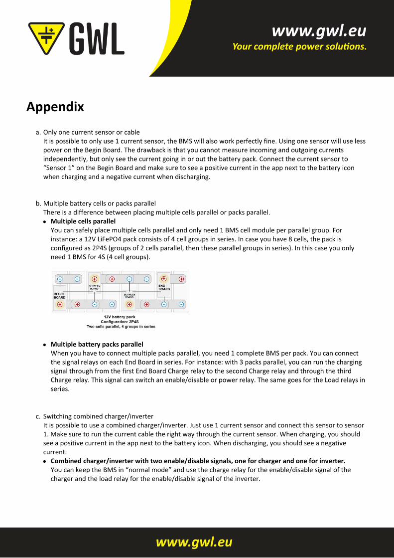
Multiple cells parallel You can safely place multiple cells parallel and only need 1 BMS cell module per parallel group. For instance: a 12V LiFePO4 pack consists of 4 cell groups in series. In case you have 8 cells, the pack is configured as 2P4S (groups of 2 cells parallel, then these parallel groups in series). In this case you only need 1 BMS for 4S (4 cell groups).
Multiple battery packs parallel
When you have to connect multiple packs parallel, you need 1 complete BMS per pack. You can connect the signal relays on each End Board in series. For instance: with 3 packs parallel, you can run the charging signal through from the first End Board Charge relay to the second Charge relay and through the third Charge relay. This signal can switch an enable/disable or power relay. The same goes for the Load relays in series.
c. Switching combined charger/inverter It is possible to use a combined charger/inverter. Just use 1 current sensor and connect this sensor to sensor 1. Make sure to run the current cable the right way through the current sensor. When charging, you should see a positive current in the app next to the battery icon. When discharging, you should see a negative current.
Combined charger/inverter with two enable/disable signals, one for charger and one for inverter. You can keep the BMS in “normal mode” and use the charge relay for the enable/disable signal of the charger and the load relay for the enable/disable signal of the inverter.
Combined charger/inverter with 1 enable/disable or no enable/disable signal In ”normal mode” the BMS will switch off the charge relay when the battery pack is full. However, this would mean the shared power will be switched off and the user is not able to discharge. For this case the BMS can be configured in “critical mode”. The BMS will only switch the power off in case there is a critical error condition. Connect the charge and load relay of the BMS in series to get a combined charge/load signal. Now you can switch a power relay or the enable/disable signal of the device. The charger/inverter floating voltages need to match the battery pack to operate correctly.
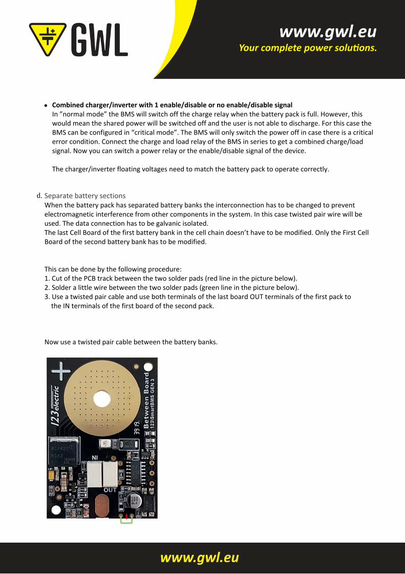
d. Separate battery sections When the battery pack has separated battery banks the interconnection has to be changed to prevent electromagnetic interference from other components in the system. In this case twisted pair wire will be used. The data connection has to be galvanic isolated. The last Cell Board of the first battery bank in the cell chain doesn’t have to be modified. Only the First Cell Board of the second battery bank has to be modified. This can be done by the following procedure: 1. Cut of the PCB track between the two solder pads (red line in the picture below). 2. Solder a little wire between the two solder pads (green line in the picture below). 3. Use a twisted pair cable and use both terminals of the last board OUT terminals of the first pack to the IN terminals of the first board of the second pack. Now use a twisted pair cable between the battery banks.
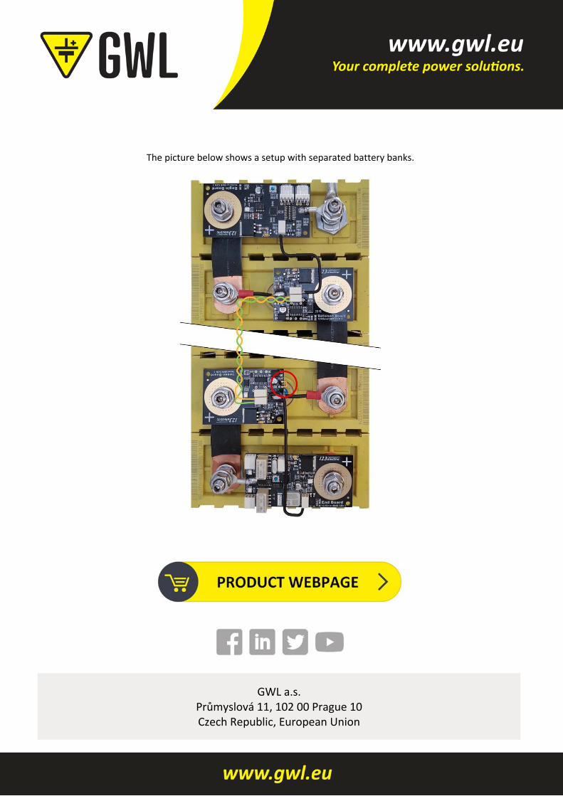
The picture below shows a setup with separated battery banks.
GWL a.s. Průmyslová 11, 102 00 Prague 10 Czech Republic, European Union