Embed Size (px)
Citation preview
SERVICE MANUAL
Part Number 99489-01YSection 1: Maintenance
Section 2: Chassis
Section 3: Engine
Section 4: Fuel System
Section 5: Starter
Section 6: Drive/Transmission
Section 7: Electrical
Appendix
HOME
A
APPENDIX A–TOOLS
Appendix A, Tools A-1
Part No. B-35316-5 12 Inch Bolt. Used with Part No. HD-39302.
Part No. B-41174 Rear Wheel Support Stand andPart No. B-41174-2 Replacement Pad
Part No. B-41177 Front Fork Holding Tool
Part No. B-41325-99 Scanalyzer Software Cartridge
Part No. B-42887 Brake Caliper Piston Remover
Part No. B-43721 Front Fork Seal Driver
Part No. B-43875 Fork Spring Compressor
Part No. B-44623 Isolator Tool
HOME
Part No. B-45110 Shock Preload Adjustment Tools
Part No. B-59000A Pro Level Oil Gauge
Part No. HD-01289 Rim Protectors
Part No. HD-21000 Tire Spreader
Part No. HD-23738 Vacuum Pump
Part No. HD-25070 Robinair Heat Gun
Part No. HD-26792 Spark Plug Tester
Part No. HD-28700 Tire Bead Expander
A-2 Appendix A, Tools
HOME
Part No. HD-33067 Wheel Bearing Packer
Part No. HD-33223-1 Cylinder Compression Gauge
Part No. HD-33416 Universal Driver Handle
Part No. HD-33418 Universal Puller Forcing Screw
Part No. HD-33446A Cylinder Torque Platesand Torque Plate Bolts Part No. HD-33446-86
Part No. HD-34623B Piston PinRetaining Ring Installer/Remover
Part No. HD-34643A Shoulderless Valve GuideSeal Installer
Part No. HD-34723 Valve Guide Hone (8 mm)
Appendix A, Tools A-3
HOME
Part No. HD-34730-2C Fuel Injector Test Lamp
Part No. HD-34731 Shoulderless Valve Guide Installation Tool
Part No. HD-34736B Valve Spring Compressor
Part No. HD-34740 Driver Handle and Remover. Used with HD-34643A and HD-34731.
Part No. HD-34751 Nylon Valve Guide Brush
Part No. HD-34813 Rowe Flywheel Rebuilding Jig
Part No. HD-34816 Oil Pressure Switch Wrench
Part No. HD-35102 Wrist Pin Bushing Hone (20 mm)
A-4 Appendix A, Tools
HOME
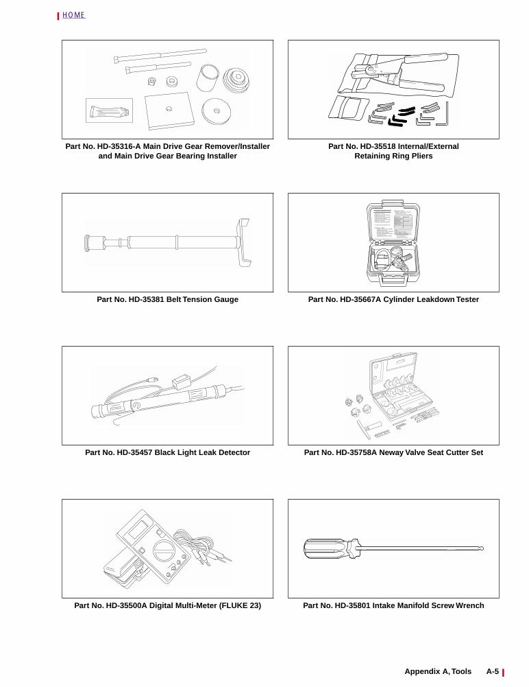
Part No. HD-35316-A Main Drive Gear Remover/Installer and Main Drive Gear Bearing Installer
Part No. HD-35381 Belt Tension Gauge
Part No. HD-35457 Black Light Leak Detector
Part No. HD-35500A Digital Multi-Meter (FLUKE 23)
Part No. HD-35518 Internal/ExternalRetaining Ring Pliers
Part No. HD-35667A Cylinder Leakdown Tester
Part No. HD-35758A Neway Valve Seat Cutter Set
Part No. HD-35801 Intake Manifold Screw Wrench
CYLINDER LEAKDOWN TESTER
JHYUYGuibikhf iugu iu ptr td6rdFoihjolm oijfollkop Yuooifoihfm knsdl hlno hslnslnnsdl hlno bs npond bpdk kznh odlbndpob npond bndb n
CYLINDER LEAKDOWN TESTER
Bdhgkjsbkdv ' ksjjlkn lkknsdl hlno hslnsln nlslns finbp pffbodlbndpob nponno[bhoknsdl hlno hslnsln nlslns finbp pffbodlbndpob npdb ndbno[bhoknsdl hlno hslnslnnsdl hlno hso[bhoknsdl hlno hslnslp pffbodlbndpob npond bndb ndbno[bho
Bdhgkjsbkdv ' ksjjlkn lk knsdl hlno hslnsln nlslns finbp pffb odlbndpob nponno[bho knsdl hlno hslnsln nlslns finbp pklhb odlbndpob npdb ndbno[bho knsdl hlno hslnslnnsdl hlno hso[bho bs npond bpdk kznh odlbndpob npond bndb ndbno[bho
Bdhgkjsbkdv ' ksjjlkn lk knsdl hlno hslnsln nlslns finbp pffb odlbndpob nponno[bho knsdl hlno hslnsln nlslns finbp pklhb
Bdhgkjsbkdv Majjlkn Nolk
knsdl hlno hslnslnndpob npondBdhgkjsbkdv hlno hslnslpknsdl hlno hslnslnndpob npond
Appendix A, Tools A-5
HOME
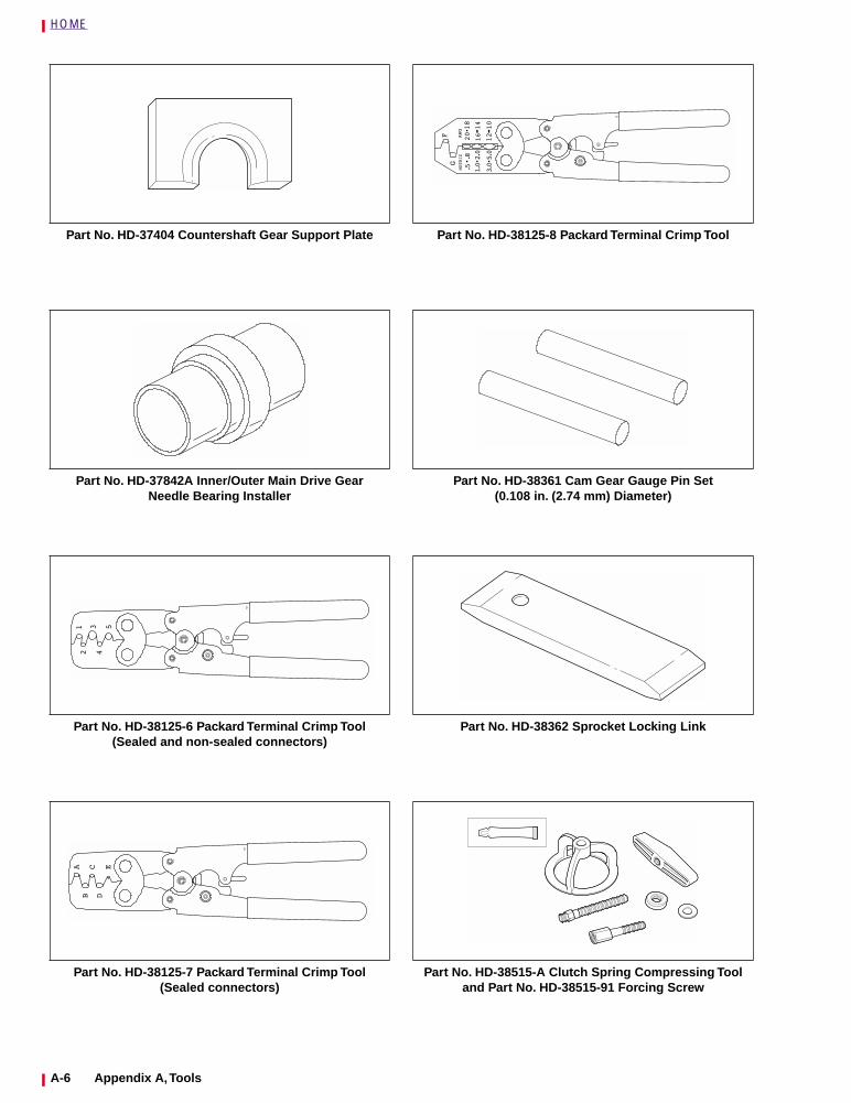
Part No. HD-37404 Countershaft Gear Support Plate
Part No. HD-37842A Inner/Outer Main Drive GearNeedle Bearing Installer
Part No. HD-38125-6 Packard Terminal Crimp Tool(Sealed and non-sealed connectors)
Part No. HD-38125-7 Packard Terminal Crimp Tool(Sealed connectors)
Part No. HD-38125-8 Packard Terminal Crimp Tool
Part No. HD-38361 Cam Gear Gauge Pin Set(0.108 in. (2.74 mm) Diameter)
Part No. HD-38362 Sprocket Locking Link
Part No. HD-38515-A Clutch Spring Compressing Tooland Part No. HD-38515-91 Forcing Screw
A-6 Appendix A, Tools
HOME
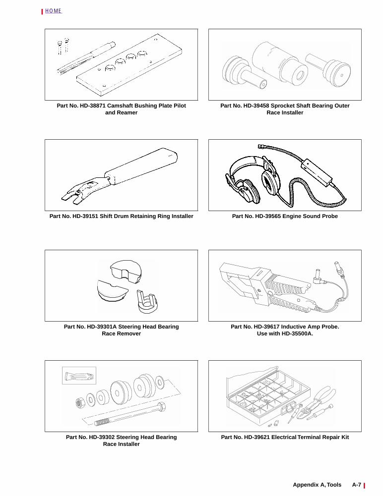
Part No. HD-38871 Camshaft Bushing Plate Pilotand Reamer
Part No. HD-39151 Shift Drum Retaining Ring Installer
Part No. HD-39301A Steering Head BearingRace Remover
Part No. HD-39302 Steering Head BearingRace Installer
Part No. HD-39458 Sprocket Shaft Bearing OuterRace Installer
Part No. HD-39565 Engine Sound Probe
Part No. HD-39617 Inductive Amp Probe.Use with HD-35500A.
Part No. HD-39621 Electrical Terminal Repair Kit
TSPOR
STER
13
CC
40
Appendix A, Tools A-7
HOME
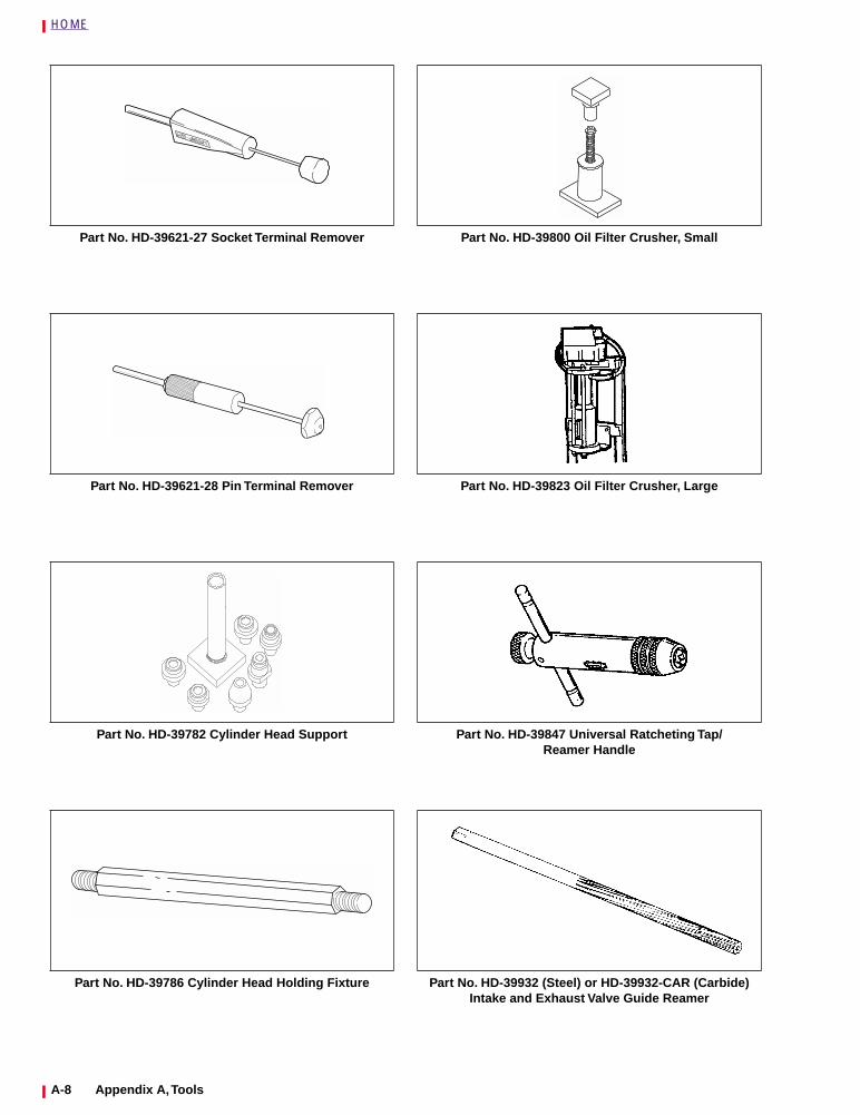
Part No. HD-39621-27 Socket Terminal Remover
Part No. HD-39621-28 Pin Terminal Remover
Part No. HD-39782 Cylinder Head Support
Part No. HD-39786 Cylinder Head Holding Fixture
Part No. HD-39800 Oil Filter Crusher, Small
Part No. HD-39823 Oil Filter Crusher, Large
Part No. HD-39847 Universal Ratcheting Tap/Reamer Handle
Part No. HD-39932 (Steel) or HD-39932-CAR (Carbide) Intake and Exhaust Valve Guide Reamer
A-8 Appendix A, Tools
HOME
Part No. HD-39964 Reamer Lubricant (Cool Tool)
Part No. HD-39965 Deutsch Terminal Crimp Tool
Part No. HD-39969 Ultra-Torch UT-100
Part No. HD-39978 Fluke 78 Multimeter (DVOM)
Part No. HD-39994 Paint Repair Kit
Part No. HD-41025 Tool Organizational System
Part No. HD-41137 Hose Clamp Pliers
Part No. HD-41155 VHS Video Shelf
Appendix A, Tools A-9

HOME
Part No. HD-41182 Fuel Pressure Gauge
Part No. HD-41183 Heat Shield AttachmentUse with Part No. HD-25070.
Part No. HD-41185 Hose Cutting Tool
Part No. HD-41185-1 Oil Hose Cutter
100
150
200
250
300350 400 450
500
550600
650
250100
10
20
30
4050 60
70
80
90
Part No. HD-41321 Sprocket Holding Tool
Part No. HD-41325 Scanalyzer
Part No. HD-41404 Test Connector Kit
Part No. HD-41496 Main Drive Gear Seal Installer
A-10 Appendix A, Tools
HOME
Part No. HD-41506 Crankshaft Locking Tool
Part No. HD-41609 Amp Terminal Crimp Tool
Part No. HD-41675 Oil Pressure Sending Unit Wrench
Part No. HD-42310 Engine/Transmission Stand
Part No. HD-42311 Oil Filter Wrench
Part No. HD-42320 Piston Pin Remover/Installer
Part No. HD-42322 Piston Support Plate
Part No. HD-42376 Battery/Charging SystemLoad Tester
600 200
Made in USA
PP-9606- 0001
Appendix A, Tools A-11
HOME
Part No. HD-42579 Sprocket Bearing/Seal Installer
Part No. HD-42774 Sprocket Shaft Seal Installer
Part No. HD-42682 Breakout Box
Part No. HD-43894 Crankshaft Locking Tool
Part No. HD-44069 Timken Snap Ring Remover/Installer
Part No. HD-44358 Flywheel Fixture (2000 Models)
Part No. HD-44404 Sprocket Shaft Inner Timken Bearing Remover
Part No. HD-94547-101 Crankshaft Bearing Outer Race Remover/Installer
A-12 Appendix A, Tools
HOME
Part No. HD-94660-37B Mainshaft Locknut Wrench
Part No. HD-94800-26A Connecting Rod Bushing Reamers and Pilots
Part No. HD-94803-67 Rear Intake CamshaftBushing Reamer
Part No. HD-94804-57 Rocker Arm Bushing Reamer
Part No. HD-94812-1 Pinion Shaft Bushing Reamer.Use with HD-94812-87.
Part No. HD-94812-87 Pinion Shaft Reamer Pilot.Use with HD-94812-1.
Part No. HD-95017-61 Large External RetainingRing Pliers
Part No. HD-95635-46 All-Purpose Claw Puller
Appendix A, Tools A-13
HOME
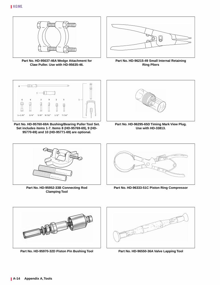
Part No. HD-95637-46A Wedge Attachment forClaw Puller. Use with HD-95635-46.
Part No. HD-95760-69A Bushing/Bearing Puller Tool Set. Set includes items 1-7. Items 8 (HD-95769-69), 9 (HD-
95770-69) and 10 (HD-95771-69) are optional.
Part No. HD-95952-33B Connecting RodClamping Tool
Part No. HD-95970-32D Piston Pin Bushing Tool
Part No. HD-96215-49 Small Internal RetainingRing Pliers
Part No. HD-96295-65D Timing Mark View Plug.Use with HD-33813.
Part No. HD-96333-51C Piston Ring Compressor
Part No. HD-96550-36A Valve Lapping Tool
A-14 Appendix A, Tools
HOME
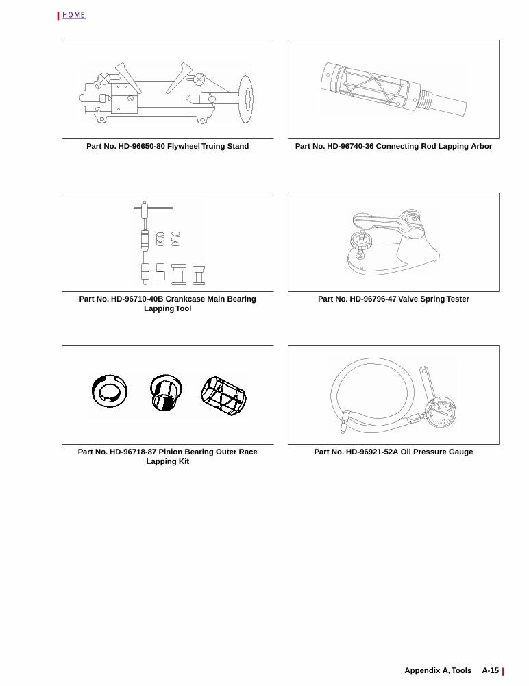
Part No. HD-96650-80 Flywheel Truing Stand
Part No. HD-96710-40B Crankcase Main Bearing Lapping Tool
Part No. HD-96718-87 Pinion Bearing Outer Race Lapping Kit
Part No. HD-96740-36 Connecting Rod Lapping Arbor
Part No. HD-96796-47 Valve Spring Tester
Part No. HD-96921-52A Oil Pressure Gauge
Appendix A, Tools A-15
HOME
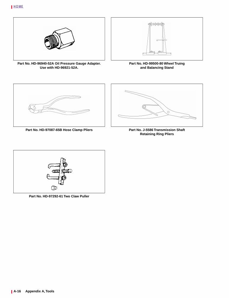
Part No. HD-96940-52A Oil Pressure Gauge Adapter.Use with HD-96921-52A.
Part No. HD-97087-65B Hose Clamp Pliers
Part No. HD-97292-61 Two Claw Puller
Part No. HD-99500-80 Wheel Truingand Balancing Stand
Part No. J-5586 Transmission ShaftRetaining Ring Pliers
A-16 Appendix A, Tools
HOME
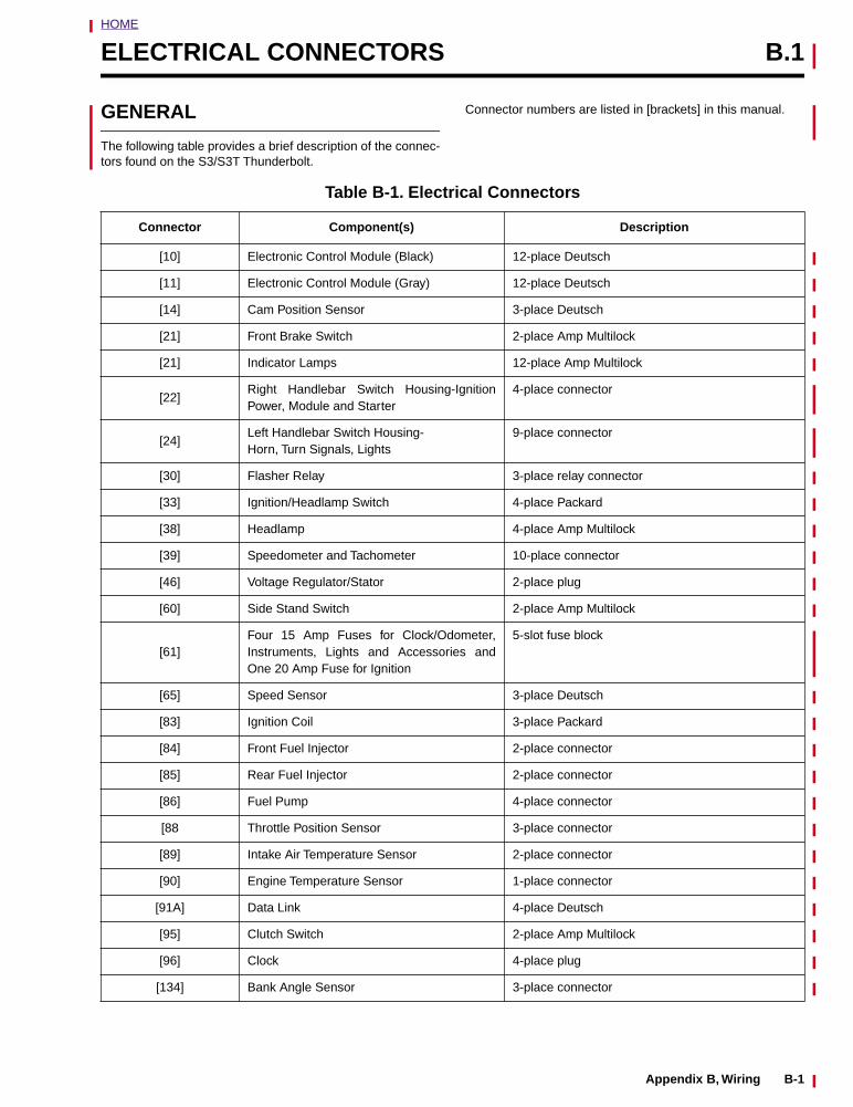
ELECTRICAL CONNECTORS B.1
GENERAL
The following table provides a brief description of the connec-tors found on the S3/S3T Thunderbolt.
Connector numbers are listed in [brackets] in this manual.
Table B-1. Electrical Connectors
Connector Component(s) Description
[10] Electronic Control Module (Black) 12-place Deutsch
[11] Electronic Control Module (Gray) 12-place Deutsch
[14] Cam Position Sensor 3-place Deutsch
[21] Front Brake Switch 2-place Amp Multilock
[21] Indicator Lamps 12-place Amp Multilock
[22]Right Handlebar Switch Housing-IgnitionPower, Module and Starter
4-place connector
[24]Left Handlebar Switch Housing-Horn, Turn Signals, Lights
9-place connector
[30] Flasher Relay 3-place relay connector
[33] Ignition/Headlamp Switch 4-place Packard
[38] Headlamp 4-place Amp Multilock
[39] Speedometer and Tachometer 10-place connector
[46] Voltage Regulator/Stator 2-place plug
[60] Side Stand Switch 2-place Amp Multilock
[61]Four 15 Amp Fuses for Clock/Odometer,Instruments, Lights and Accessories andOne 20 Amp Fuse for Ignition
5-slot fuse block
[65] Speed Sensor 3-place Deutsch
[83] Ignition Coil 3-place Packard
[84] Front Fuel Injector 2-place connector
[85] Rear Fuel Injector 2-place connector
[86] Fuel Pump 4-place connector
[88 Throttle Position Sensor 3-place connector
[89] Intake Air Temperature Sensor 2-place connector
[90] Engine Temperature Sensor 1-place connector
[91A] Data Link 4-place Deutsch
[95] Clutch Switch 2-place Amp Multilock
[96] Clock 4-place plug
[134] Bank Angle Sensor 3-place connector
Appendix B, Wiring B-1
HOME
DEUTSCH ELECTRICAL CONNECTORS B.2
GENERAL
The Deutsch Connector features a superior seal to protectelectrical contacts from dirt and moisture in harsh environ-ments.
Three and eight pin connectors are of similar constructionwith one exception: eight pin connectors use two externallatches on the socket side.
NOTE
Use the DEUTSCH Terminal Crimp Tool (Part No. HD-39965)to install Deutsch pin and socket terminals on wires. If newterminals must be installed, follow the instructions includedwith the crimping tool or see CRIMPING INSTRUCTIONS.
REMOVING/INSTALLINGSOCKETS
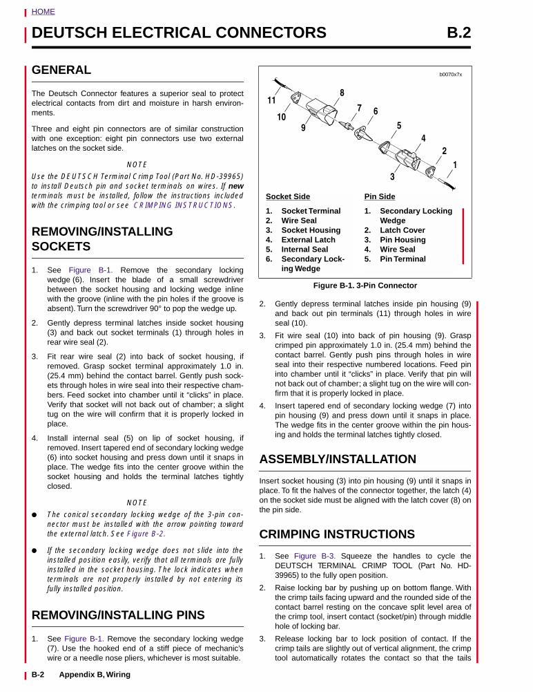
1. See Figure B-1. Remove the secondary lockingwedge (6). Insert the blade of a small screwdriverbetween the socket housing and locking wedge inlinewith the groove (inline with the pin holes if the groove isabsent). Turn the screwdriver 90° to pop the wedge up.
2. Gently depress terminal latches inside socket housing(3) and back out socket terminals (1) through holes inrear wire seal (2).
3. Fit rear wire seal (2) into back of socket housing, ifremoved. Grasp socket terminal approximately 1.0 in.(25.4 mm) behind the contact barrel. Gently push sock-ets through holes in wire seal into their respective cham-bers. Feed socket into chamber until it “clicks” in place.Verify that socket will not back out of chamber; a slighttug on the wire will confirm that it is properly locked inplace.
4. Install internal seal (5) on lip of socket housing, ifremoved. Insert tapered end of secondary locking wedge(6) into socket housing and press down until it snaps inplace. The wedge fits into the center groove within thesocket housing and holds the terminal latches tightlyclosed.
NOTE
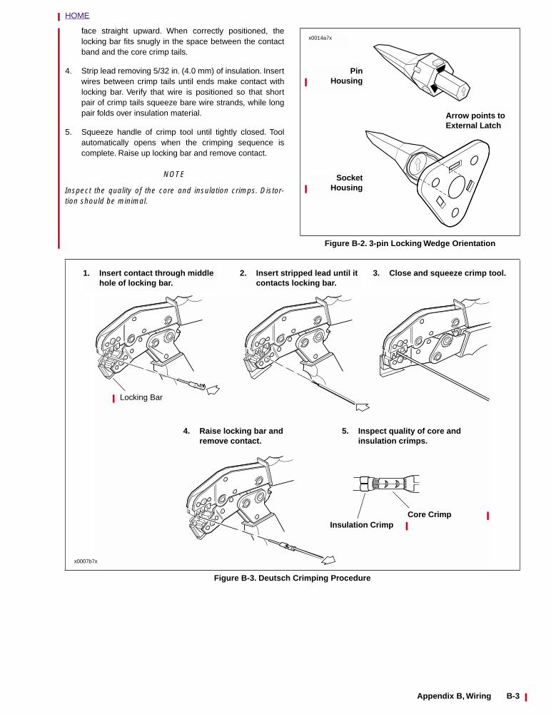
● The conical secondary locking wedge of the 3-pin con-nector must be installed with the arrow pointing towardthe external latch. See Figure B-2.
● If the secondary locking wedge does not slide into theinstalled position easily, verify that all terminals are fullyinstalled in the socket housing. The lock indicates whenterminals are not properly installed by not entering itsfully installed position.
REMOVING/INSTALLING PINS
1. See Figure B-1. Remove the secondary locking wedge(7). Use the hooked end of a stiff piece of mechanic’swire or a needle nose pliers, whichever is most suitable.
2. Gently depress terminal latches inside pin housing (9)and back out pin terminals (11) through holes in wireseal (10).
3. Fit wire seal (10) into back of pin housing (9). Graspcrimped pin approximately 1.0 in. (25.4 mm) behind thecontact barrel. Gently push pins through holes in wireseal into their respective numbered locations. Feed pininto chamber until it “clicks” in place. Verify that pin willnot back out of chamber; a slight tug on the wire will con-firm that it is properly locked in place.
4. Insert tapered end of secondary locking wedge (7) intopin housing (9) and press down until it snaps in place.The wedge fits in the center groove within the pin hous-ing and holds the terminal latches tightly closed.
ASSEMBLY/INSTALLATION
Insert socket housing (3) into pin housing (9) until it snaps inplace. To fit the halves of the connector together, the latch (4)on the socket side must be aligned with the latch cover (8) onthe pin side.
CRIMPING INSTRUCTIONS
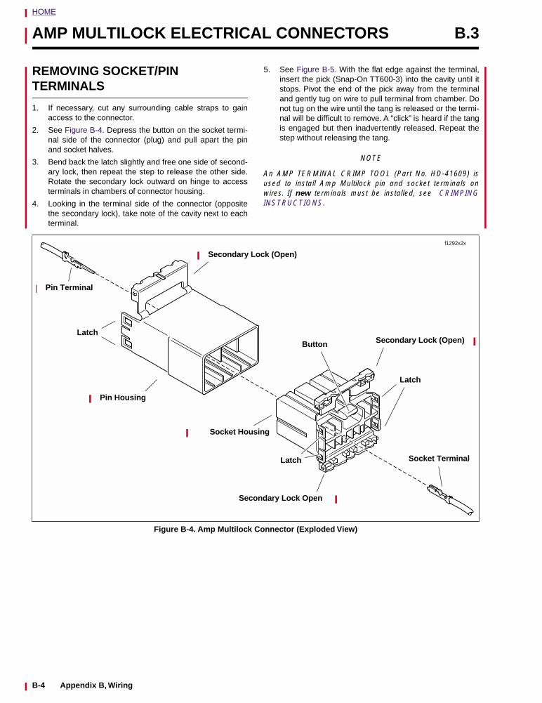
1. See Figure B-3. Squeeze the handles to cycle theDEUTSCH TERMINAL CRIMP TOOL (Part No. HD-39965) to the fully open position.
2. Raise locking bar by pushing up on bottom flange. Withthe crimp tails facing upward and the rounded side of thecontact barrel resting on the concave split level area ofthe crimp tool, insert contact (socket/pin) through middlehole of locking bar.
3. Release locking bar to lock position of contact. If thecrimp tails are slightly out of vertical alignment, the crimptool automatically rotates the contact so that the tails
Figure B-1. 3-Pin Connector
11
109
8
7 6
54
3
21
b0070x7x
Pin Side
1. Secondary Locking Wedge
2. Latch Cover3. Pin Housing4. Wire Seal5. Pin Terminal
Socket Side
1. Socket Terminal2. Wire Seal3. Socket Housing4. External Latch5. Internal Seal6. Secondary Lock-
ing Wedge
B-2 Appendix B, Wiring
HOME
face straight upward. When correctly positioned, thelocking bar fits snugly in the space between the contactband and the core crimp tails.
4. Strip lead removing 5/32 in. (4.0 mm) of insulation. Insertwires between crimp tails until ends make contact withlocking bar. Verify that wire is positioned so that shortpair of crimp tails squeeze bare wire strands, while longpair folds over insulation material.
5. Squeeze handle of crimp tool until tightly closed. Toolautomatically opens when the crimping sequence iscomplete. Raise up locking bar and remove contact.
NOTE
Inspect the quality of the core and insulation crimps. Distor-tion should be minimal.
Figure B-2. 3-pin Locking Wedge Orientation
x0014a7x
SocketHousing
PinHousing
Arrow points to External Latch
Figure B-3. Deutsch Crimping Procedure
1. Insert contact through middle hole of locking bar.
2. Insert stripped lead until it contacts locking bar.
3. Close and squeeze crimp tool.
4. Raise locking bar and remove contact.
5. Inspect quality of core and insulation crimps.
x0007b7x
Locking Bar
Insulation CrimpCore Crimp
Appendix B, Wiring B-3
HOME
AMP MULTILOCK ELECTRICAL CONNECTORS B.3
REMOVING SOCKET/PINTERMINALS
1. If necessary, cut any surrounding cable straps to gainaccess to the connector.
2. See Figure B-4. Depress the button on the socket termi-nal side of the connector (plug) and pull apart the pinand socket halves.
3. Bend back the latch slightly and free one side of second-ary lock, then repeat the step to release the other side.Rotate the secondary lock outward on hinge to accessterminals in chambers of connector housing.
4. Looking in the terminal side of the connector (oppositethe secondary lock), take note of the cavity next to eachterminal.
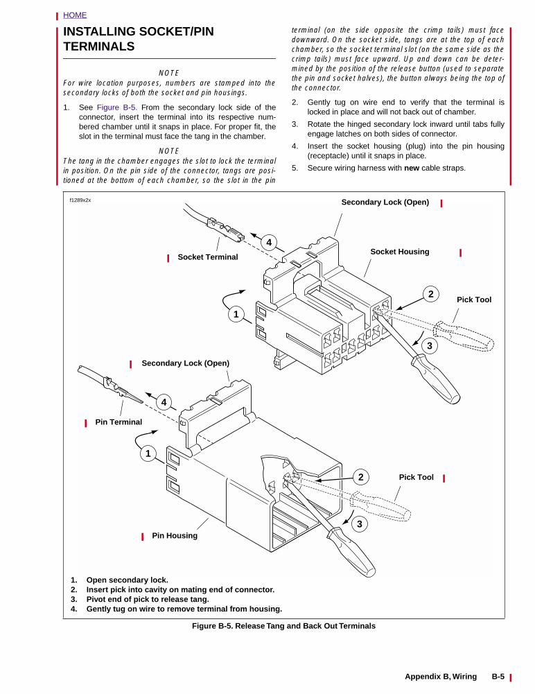
5. See Figure B-5. With the flat edge against the terminal,insert the pick (Snap-On TT600-3) into the cavity until itstops. Pivot the end of the pick away from the terminaland gently tug on wire to pull terminal from chamber. Donot tug on the wire until the tang is released or the termi-nal will be difficult to remove. A “click” is heard if the tangis engaged but then inadvertently released. Repeat thestep without releasing the tang.
NOTE
An AMP TERMINAL CRIMP TOOL (Part No. HD-41609) isused to install Amp Multilock pin and socket terminals onwires. If new terminals must be installed, see CRIMPINGINSTRUCTIONS.
Figure B-4. Amp Multilock Connector (Exploded View)
Pin Terminal
Latch
Pin Housing
Socket Housing
Secondary Lock Open
Secondary Lock (Open)
Latch
Latch
Button
Secondary Lock (Open)
Socket Terminal
f1292x2x
B-4 Appendix B, Wiring
HOME
INSTALLING SOCKET/PIN TERMINALS
NOTEFor wire location purposes, numbers are stamped into thesecondary locks of both the socket and pin housings.
1. See Figure B-5. From the secondary lock side of theconnector, insert the terminal into its respective num-bered chamber until it snaps in place. For proper fit, theslot in the terminal must face the tang in the chamber.
NOTEThe tang in the chamber engages the slot to lock the terminalin position. On the pin side of the connector, tangs are posi-tioned at the bottom of each chamber, so the slot in the pin
terminal (on the side opposite the crimp tails) must facedownward. On the socket side, tangs are at the top of eachchamber, so the socket terminal slot (on the same side as thecrimp tails) must face upward. Up and down can be deter-mined by the position of the release button (used to separatethe pin and socket halves), the button always being the top ofthe connector.
2. Gently tug on wire end to verify that the terminal islocked in place and will not back out of chamber.
3. Rotate the hinged secondary lock inward until tabs fullyengage latches on both sides of connector.
4. Insert the socket housing (plug) into the pin housing(receptacle) until it snaps in place.
5. Secure wiring harness with new cable straps.
Figure B-5. Release Tang and Back Out Terminals
Pin Terminal
Pin Housing
Secondary Lock (Open)
Secondary Lock (Open)
Pick Tool
Socket TerminalSocket Housing
Pick Tool
4
1
3
2
1
4
2
3
1. Open secondary lock.2. Insert pick into cavity on mating end of connector.3. Pivot end of pick to release tang.4. Gently tug on wire to remove terminal from housing.
f1289x2x
Appendix B, Wiring B-5
HOME
CRIMPING INSTRUCTIONS
1. See Figure B-7. Squeeze the handles to cycle the AMPTERMINAL CRIMP TOOL (Part No. HD-41609) to thefully open position.
2. Raise locking bar by pushing up on bottom flange. Withthe crimp tails facing upward, insert contact (socket/pin)through locking bar, so that the closed side of the contactrests on the nest (concave split level area) of the crimptool). Use the front nest for 20 gauge wire, the middle for16 gauge and the rear for 18 gauge.
3. Release locking bar to lock position of contact. Whencorrectly positioned, the locking bar fits snugly in thespace at the front of the core crimp tails.
4. Strip lead removing 5/32 in. (4.0 mm) of insulation. Insertwires between crimp tails until ends make contact withlocking bar. Verify that wire is positioned so that shortpair of crimp tails squeeze bare wire strands, while longpair folds over insulation material.
5. Squeeze handle of crimp tool until tightly closed. Toolautomatically opens when the crimping sequence iscomplete. Raise up locking bar and remove contact.
6. See Figure B-7. Inspect the quality of the core and insu-lation crimps. Distortion should be minimal.
Figure B-6. Crimps
b0239x7x
12 3
4
12 3 4
Pin Terminal
Socket Terminal
1. Insulation Crimp Tail2. Core Crimp Tail3. Locking Groove Bar4. Tang Slot
Figure B-7. Amp Multilock Crimping Procedure
b0238x7x
1. Raise locking bar andseat contact on nest ofcrimp tool. Releaselocking tool.
7. Insert stripped leaduntil it contacts lockingbar.
7. Close and squeezecrimp tool.
7. Raise locking bar andremove contact
B-6 Appendix B, Wiring
HOME
APPENDIX C–METRIC CONVERSIONS C.1
Table C-1. Metric Conversions
MILLIMETERS to INCHES(mm x 0.03937 = inches)
INCHES to MILLIMETERS(inches x 25.40 = mm)
mm in. mm in. mm in. mm in. in. mm in. mm in. mm in. mm
.1
.2
.3
.4
.5
.6
.7
.8
.9
1
2
3
4
5
6
7
8
9
10
11
12
13
14
15
16
17
18
19
20
21
22
23
24
.0039
.0078
.0118
.0157
.0197
.0236
.0275
.0315
.0354
.0394
.0787
.1181
.1575
.1968
.2362
.2756
.3149
.3543
.3937
.4331
.4724
.5118
.5512
.5905
.6299
.6693
.7086
.7480
.7874
.8268
.8661
.9055
.9449
25
26
27
28
29
30
31
32
33
34
35
36
37
38
39
40
41
42
43
44
45
46
47
48
49
50
51
52
53
54
55
56
57
.9842
1.024
1.063
1.102
1.142
1.181
1.220
1.260
1.299
1.338
1.378
1.417
1.456
1.496
1.535
1.575
1.614
1.653
1.693
1.732
1.772
1.811
1.850
1.890
1.929
1.968
2.008
2.047
2.086
2.126
2.165
2.205
2.244
58
59
60
61
62
63
64
65
66
67
68
69
70
71
72
73
74
75
76
77
78
79
80
81
82
83
84
85
86
87
88
89
90
2.283
2.323
2.362
2.401
2.441
2.480
2.519
2.559
2.598
2.638
2.677
2.716
2.756
2.795
2.834
2.874
2.913
2.953
2.992
3.031
3.071
3.110
3.149
3.189
3.228
3.268
3.307
3.346
3.386
3.425
3.464
3.504
3.543
91
92
93
94
95
96
97
98
99
100
101
102
103
104
105
106
107
108
109
110
111
112
113
114
115
116
117
118
119
120
121
122
123
3.582
3.622
3.661
3.701
3.740
3.779
3.819
3.858
3.897
3.937
3.976
4.016
4.055
4.094
4.134
4.173
4.212
4.252
4.291
4.331
4.370
4.409
4.449
4.488
4.527
4.567
4.606
4.645
4.685
4.724
4.764
4.803
4.842
.001
.002
.003
.004
.005
.006
.007
.008
.009
.010
1/64
.020
.030
1/32
.040
.050
.060
1/16
.070
.080
.090
.1
1/8
3/16
.2
1/4
.3
5/16
3/8
.4
7/16
1/2
9/16
.025
.051
.076
.102
.127
.152
.178
.203
.229
.254
.397
.508
.762
.794
1.016
1.270
1.524
1.588
1.778
2.032
2.286
2.540
3.175
4.762
5.080
6.350
7.620
7.938
9.525
10.160
11.112
12.700
14.288
.6
5/8
11/16
.7
3/4
.8
13/16
7/8
.9
15/16
1
1 1/16
1.1
1 1/8
1 3/16
1.2
1 1/4
1.3
1 5/16
1 3/8
1.4
1 7/16
1 1/2
1 9/16
1.6
1 5/8
1 11/16
1.7
1 3/4
1.8
1 13/16
1 7/8
1.9
15.240
15.875
17.462
17.780
19.050
20.320
20.638
22.225
22.860
23.812
25.40
26.99
27.94
28.57
30.16
30.48
31.75
33.02
33.34
34.92
35.56
36.51
38.10
39.69
40.64
41.27
42.86
43.18
44.45
45.72
46.04
47.62
48.26
1 15/16
2
2 1/16
2.1
2 1/8
2 3/16
2.2
2 1/4
2.3
2 5/16
2 3/8
2.4
2 7/16
2 1/2
2 9/16
2.6
2 5/8
2 11/16
2.7
2 3/4
2.8
2 13/16
2 7/8
2.9
2 15/16
3
3 1/16
3.1
3 1/8
3 3/16
3.2
3 1/4
3.3
49.21
50.80
52.39
53.34
53.97
55.56
55.88
57.15
58.42
58.74
60.32
60.96
61.91
63.50
65.09
66.04
66.67
68.26
68.58
69.85
71.12
71.44
73.02
73.66
74.61
76.20
77.79
78.74
79.37
80.96
81.28
82.55
83.82
3 5/16
3 3/8
3.4
3 7/16
3 1/2
3 9/16
3.6
3 5/8
3 11/16
3.7
3 3/4
3.8
3 13/16
3 7/8
3.9
3 15/16
4
4 1/16
4.1
4 1/8
4 3/16
4.2
4 1/4
4.3
4 5/16
4 3/8
4.4
4 7/16
4 1/2
4 9/16
4.6
4 5/8
4 11/16
84.14
85.72
86.36
87.31
88.90
90.49
91.44
92.07
93.66
93.98
95.25
96.52
96.84
98.42
99.06
100.01
101.6
102.19
104.14
104.77
106.36
106.68
107.95
109.22
109.54
111.12
111.76
112.71
114.30
115.89
116.84
117.47
119.06
Appendix C, Conversions C-1
HOME
TORQUE MASTER VALUES C.2
GENERAL
Torque specifications for specific components are listed ineach section at the point of use. When converting to Newton-meters, use the formulas given under the metric chart. For allother steel fasteners, use the values listed in one of thetables below. In the English table, torque figures are listed inft-lbs, except those marked with an asterisk (*), which arelisted in in-lbs. In the metric table, figures are listed in New-ton-meters.
1WARNING 1WARNING
The quality fasteners used on Buell motorcycles havespecific strength, finish and type requirements to per-form properly in the assembly and the operating environ-ment. Use only genuine Buell replacement fastenerstightened to the proper torque. Substitution could causefastener failure, which could result in death or seriousinjury.
*Torque values in in-lbs.
foot-pounds (ft-lbs) x 1.356 = Newton-meters (Nm)inch-pounds (in-lbs) x 0.113 = Newton-meters (Nm)
Table C-2. English Torque Values
FASTENER TYPEMINIMUM TENSILE
STRENGTHMATERIAL
BODY SIZE OR OUTSIDE DIAMETER# (number) in. (inches)
2 3 4 5 6 8 10 1/4 5/16 3/8 7/16 1/2 9/16 5/8 3/4 7/8 1
SAE 2STEEL
74,000PSI
LOWCARBON 6 12 20 32 47 69 96 155 206 310
SAE 5STEEL
120,000PSI
MEDIUMCARBON HEAT
TREAT14* 22* 10 19 33 54 78 114 154 257 382 587
SAE 7STEEL
133,000PSI
MEDIUMCARBON
ALLOY13 25 44 71 110 154 215 360 570 840
SAE 8STEEL
150,000PSI
MEDIUMCARBON
ALLOY14 29 47 78 119 169 230 380 600 900
SAE 8STEEL
150,000PSI
MEDIUMCARBON
ALLOY14 29 47 78 119 169 230 380 600 900
SOCKET SET
SCREW
212,000PSI
HIGH CARBON QUENCHED TEMPERED
9* 16* 30* 70* 140* 18 29 43 63 100 146
STUDS Use SAE 2, 5 and 8 values when grade is known, with nut of sufficient strength.
Table C-3. Metric Torque Values
FASTENER TYPEMINIMUM TENSILE
STRENGTHMATERIAL
BODY SIZE OR OUTSIDE DIAMETER# (number) mm (millimeters)
2 3 4 5 6 8 10 6.4 7.9 9.5 11.1 12.7 14.3 15.9 19.1 22.2 25.4
SAE 2STEEL
5,202kg/cm2
LOWCARBON 8.3 16.6 27.7 44.3 65.0 95.4 132.8 214.4 283.5 428.7
SAE 5STEEL
8,436kg/cm2
MEDIUMCARBON HEAT
TREAT1.6 2.5 13.8 26.3 45.6 74.7 107.9 157.7 213.0 355.4 528.3 811.8
SAE 7STEEL
9,350kg/cm2
MEDIUMCARBON
ALLOY18.0 34.6 60.8 98.2 152.1 213.0 297.3 497.9 788.3 1161.7
SAE 8STEEL
10,545kg/cm2
MEDIUMCARBON
ALLOY19.4 40.1 65.0 107.9 164.6 233.7 318.1 525.5 829.8 1220.0
SAE 8STEEL
10,545kg/cm2
MEDIUMCARBON
ALLOY19.4 40.1 65.0 107.9 164.6 233.7 318.1 525.5 829.8 1220.0
SOCKET SET
SCREW
14,904kg/cm2
HIGH CARBON QUENCHED TEMPERED
1.0 1.8 3.4 8.1 16.1 24.9 40.1 59.5 87.1 138.3 201.9
STUDS Use SAE 2, 5 and 8 values when grade is known, with nut of sufficient strength.
C-2 Appendix C, Conversions
MAINTENANCE 1
Table Of Contents
SUBJECT PAGE NO.
1.1 General . . . . . . . . . . . . . . . . . . . . . . . . . . . . . . . . . . . . . . . . . . . . . . . . . . . . . . 1-11.2 Fluid Requirements . . . . . . . . . . . . . . . . . . . . . . . . . . . . . . . . . . . . . . . . . . . . . 1-51.3 Battery . . . . . . . . . . . . . . . . . . . . . . . . . . . . . . . . . . . . . . . . . . . . . . . . . . . . . . . 1-111.4 Engine Lubrication System . . . . . . . . . . . . . . . . . . . . . . . . . . . . . . . . . . . . . . . 1-141.5 Brakes . . . . . . . . . . . . . . . . . . . . . . . . . . . . . . . . . . . . . . . . . . . . . . . . . . . . . . . 1-161.6 Brake Pads and Rotors . . . . . . . . . . . . . . . . . . . . . . . . . . . . . . . . . . . . . . . . . . 1-191.7 Tires and Wheels . . . . . . . . . . . . . . . . . . . . . . . . . . . . . . . . . . . . . . . . . . . . . . . 1-201.8 Clutch . . . . . . . . . . . . . . . . . . . . . . . . . . . . . . . . . . . . . . . . . . . . . . . . . . . . . . . . 1-211.9 Drive Belt Deflection . . . . . . . . . . . . . . . . . . . . . . . . . . . . . . . . . . . . . . . . . . . . 1-231.10 Drive Belt and Sprocket . . . . . . . . . . . . . . . . . . . . . . . . . . . . . . . . . . . . . . . . . 1-251.11 Primary Chain . . . . . . . . . . . . . . . . . . . . . . . . . . . . . . . . . . . . . . . . . . . . . . . . 1-271.12 Preload Adjustment . . . . . . . . . . . . . . . . . . . . . . . . . . . . . . . . . . . . . . . . . . . . 1-291.13 Suspension Damping Adjustments . . . . . . . . . . . . . . . . . . . . . . . . . . . . . . . . 1-311.14 Front Fork . . . . . . . . . . . . . . . . . . . . . . . . . . . . . . . . . . . . . . . . . . . . . . . . . . . 1-331.15 Steering Head Bearings . . . . . . . . . . . . . . . . . . . . . . . . . . . . . . . . . . . . . . . . . 1-341.16 Spark Plugs . . . . . . . . . . . . . . . . . . . . . . . . . . . . . . . . . . . . . . . . . . . . . . . . . . 1-351.17 Air Cleaner . . . . . . . . . . . . . . . . . . . . . . . . . . . . . . . . . . . . . . . . . . . . . . . . . . . 1-361.18 Ignition Timing . . . . . . . . . . . . . . . . . . . . . . . . . . . . . . . . . . . . . . . . . . . . . . . . 1-371.19 Handlebars . . . . . . . . . . . . . . . . . . . . . . . . . . . . . . . . . . . . . . . . . . . . . . . . . . 1-391.20 Throttle Cables . . . . . . . . . . . . . . . . . . . . . . . . . . . . . . . . . . . . . . . . . . . . . . . 1-401.21 Headlamp . . . . . . . . . . . . . . . . . . . . . . . . . . . . . . . . . . . . . . . . . . . . . . . . . . . 1-411.22 Storage . . . . . . . . . . . . . . . . . . . . . . . . . . . . . . . . . . . . . . . . . . . . . . . . . . . . . 1-421.23 Troubleshooting . . . . . . . . . . . . . . . . . . . . . . . . . . . . . . . . . . . . . . . . . . . . . . . 1-43

HOME
GENERAL 1.1
SERVICING A NEW MOTORCYCLE
11WARNING1WARNING
Always follow the listed service and maintenance recom-mendations, because they affect the safe operation ofthe motorcycle and the personal welfare of the rider. Fail-ure to follow recommendations could result in death orserious injury.
Service operations to be performed before customer deliveryare specified in the applicable model year PREDELIVERYAND SETUP MANUAL.
The performance of new motorcycle initial service is requiredto keep warranty in force and to ensure proper emissionssystems operation.
After a new motorcycle has been driven its first 500 miles(800 km), and at every 2500 mile (4000 km) intervalthereafter, have a Buell dealer perform the service operationslisted in Table 1-3.
SAFE OPERATING MAINTENANCE
CAUTION
● Do not attempt to retighten engine head bolts.Retightening can cause engine damage.
● During the initial 500 mile (800 km) break-in period,use only Harley-Davidson 20W50 engine oil. Failureto use the recommended oil may result in improperbreak-in of the engine cylinders and piston rings.
A careful check of certain equipment is necessary afterperiods of storage, and frequently between regular serviceintervals, to determine if additional maintenance is required.
Check:
1. Tires for abrasions, cuts and correct pressure.
2. Secondary drive belt for proper tension and condition.
3. Brakes, steering and throttle for responsiveness.
4. Brake fluid level and condition. Hydraulic lines andfittings for leaks. Also, check brake pads and rotors forwear.
5. Cables for fraying, crimping and free operation.
6. Engine oil and transmission fluid levels.
7. Headlamp, passing lamp, tail lamp, brake lamp and turnsignal operation.
SHOP PRACTICES
Repair Notes
NOTE● General maintenance practices are given in this section.
● Repair = Disassembly/Assembly.
● Replace = Removal/Installation.
All special tools and torque values are noted at the point ofuse.
All required parts or materials can be found in the appropriatePARTS CATALOG.
Safety
Safety is always the most important consideration whenperforming any job. Be sure you have a completeunderstanding of the task to be performed. Use commonsense. Use the proper tools. Protect yourself and bystanderswith approved eye protection. Don’t just do the job – do thejob safely.
Removing Parts
Always consider the weight of a part when lifting. Use a hoistwhenever necessary. Do not lift heavy parts by hand. A hoistand adjustable lifting beam or sling are needed to removesome parts. The lengths of chains or cables from the hoist tothe part should be equal and parallel and should bepositioned directly over the center of the part. Be sure that noobstructions will interfere with the lifting operation. Neverleave a part suspended in mid-air.
Always use blocking or proper stands to support the part thathas been hoisted. If a part cannot be removed, verify that allbolts and attaching hardware have been removed. Check tosee if any parts are in the way of the part being removed.
When removing hoses, wiring or tubes, always tag each partto ensure proper installation.
Cleaning
If you intend to reuse parts, follow good shop practice andthoroughly clean the parts before assembly. Keep all dirt outof parts; the unit will perform better and last longer. Seals,filters and covers are used in this vehicle to keep outenvironmental dirt and dust. These items must be kept ingood condition to ensure satisfactory operation.
Clean and inspect all parts as they are removed. Be sure allholes and passages are clean and open. After cleaning,cover all parts with clean lint-free cloth, paper or othermaterial. Be sure the part is clean when it is installed.
Always clean around lines or covers before they are removed.Plug, tape or cap holes and openings to keep out dirt, dustand debris.
Disassembly and Assembly
Always assemble or disassemble one part at a time. Do notwork on two assemblies simultaneously. Be sure to make allnecessary adjustments. Recheck your work when finished.Be sure that everything is done.
Operate the vehicle to perform any final check oradjustments. If all is correct, the vehicle is ready to go back tothe customer.
2001 Buell S3/S3T: Maintenance 1-1
HOME
Checking Torques on Fasteners with Lock Patches/Loctite ThreadlockerTo check the torque on a fastener that has a lock patch do thefollowing:
1. Set the torque wrench for the lowest setting in the giventorque range for the fastener.
2. Attempt to tighten fastener to set torque. If fastener doesnot move and lowest setting is satisfied (torque wrenchclicks), then the proper torque has been maintained bythe fastener.
3. If the fastener does move, remove the fastener, reapplythe appropriate type of LOCTITE THREADLOCKER andtighten the fastener to Service Manual specification.
REPAIR AND REPLACEMENT PROCEDURES
Hardware and Threaded PartsInstall helical thread inserts when inside threads in castingsare stripped, damaged or not capable of withstandingspecified torque.
Replace bolts, nuts, studs, washers, spacers and smallcommon hardware if missing or in any way damaged. Cleanup or repair minor thread damage with a suitable tap or die.
Replace all damaged or missing lubrication fittings.
Use Teflon pipe sealant on pipe fitting threads.
Wiring, Hoses and LinesReplace hoses, clamps, electrical wiring, electrical switchesor fuel lines if they do not meet specifications.
Instruments and GaugesReplace broken or defective instruments and gauges.Replace dials and glass that are so scratched or discoloredthat reading is difficult.
BearingsAnti-friction bearings must be handled in a special way. Tokeep out dirt and abrasives, cover the bearings as soon asthey are removed from the package.
1CAUTION
Never use compressed air to “spin-dry” bearings. Veryhigh bearing speeds can damage un-lubricated bearings.Spinning bearings with compressed air can also cause abearing to fly apart, which may result in minor or moder-ate injury.
Wash bearings in a non-flammable cleaning solution. Knockout packed lubricant inside by tapping the bearing against awooden block. Wash bearings again. Cover bearings withclean material after setting them down to dry.
Coat bearings with clean oil. Wrap bearings in clean paper.
Be sure that the chamfered side of the bearing always facesthe shoulder (when bearings installed against shoulders).Lubricate bearings and all metal contact surfaces before
pressing into place. Only apply pressure on the part of thebearing that makes direct contact with the mating part.
Always use the proper tools and fixtures for removing andinstalling bearings.
Bearings do not usually need to be removed. Only removebearings if necessary.
Bushings
Do not remove a bushing unless damaged, excessively wornor loose in its bore. Press out bushings that must bereplaced.
When pressing or driving bushings, be sure to apply pressurein line with the bushing bore. Use a bearing/bushing driver ora bar with a smooth, flat end. Never use a hammer to drivebushings.
Inspect the bushing and the mated part for oil holes. Be sureall oil holes are properly aligned.
Gaskets
Always discard gaskets after removal. Replace with newgaskets. Never use the same gasket twice. Be sure thatgasket holes match up with holes in the mating part.
Lip Type Seals
Lip seals are used to seal oil or grease and are usuallyinstalled with the sealing lip facing the contained lubricant.Seal orientation, however, may vary under differentapplications.
Seals should not be removed unless necessary. Only removeseals if required to gain access to other parts or if sealdamage or wear dictates replacement.
Leaking oil or grease usually means that a seal is damaged.Replace leaking seals to prevent overheated bearings.
Always discard seals after removal. Do not use the same sealtwice.
O-Rings (Preformed Packings)
Always discard O-rings after removal. Replace with new O-rings. To prevent leaks, lubricate the O-rings beforeinstallation. Apply the same type of lubricant as that beingsealed. Be sure that all gasket, O-ring and seal matingsurfaces are thoroughly clean before installation.
Gears
Always check gears for damaged or worn teeth.
Lubricate mating surfaces before pressing gears on shafts.
1-2 2001 Buell S3/S3T: Maintenance
HOME
Shafts
If a shaft does not come out easily, check that all nuts, boltsor retaining rings have been removed. Check to see if otherparts are in the way before using force.
Shafts fitted to tapered splines should be very tight. If shaftsare not tight, disassemble and inspect tapered splines.Discard parts that are worn. Be sure tapered splines areclean, dry and free of burrs before putting them in place.Press mating parts together tightly.
Clean all rust from the machined surfaces of new parts.
Part Replacement
Always replace worn or damaged parts with new parts.
CLEANING
Part Protection
Before cleaning, protect rubber parts (such as hoses, bootsand electrical insulation) from cleaning solutions. Use agrease-proof barrier material. Remove the rubber part if itcannot be properly protected.
Cleaning Process
Any cleaning method may be used as long as it does notresult in parts damage. Thorough cleaning is necessary forproper parts inspection. Strip rusted paint areas to bare metalbefore repainting.
Rust or Corrosion Removal
Remove rust and corrosion with a wire brush, abrasive cloth,sand blasting, vapor blasting or rust remover. Use buffingcrocus cloth on highly polished parts that are rusted.
Bearings
Remove shields and seals from bearings before cleaning.Clean bearings with permanent shields and seals in solution.
Clean open bearings by soaking them in a petroleumcleaning solution. Never use a solution that contains chlorine.
1CAUTION
Never use compressed air to “spin-dry” bearings. Veryhigh bearing speeds can damage un-lubricated bearings.Spinning bearings with compressed air can also cause abearing to fly apart, which may result in minor or moder-ate injury.
Let bearings stand and dry. Do not dry using compressed air.Do not spin bearings while they are drying.
INSPECTING
Leak Dye
When using leak dye with the black light leak detector, add 1/4 oz. (7.4 ml) of dye for each 1 quart (0.9 l) of fluid in thesystem being checked.
TOOL SAFETY
Air Tools● Always use approved eye protection equipment when
performing any task using air-operated tools.
● On all power tools, use only recommended accessorieswith proper capacity ratings.
● Do not exceed air pressure ratings of any power tools.
● Bits should be placed against work surface before airhammers are operated.
● Disconnect the air supply line to an air hammer beforeattaching a bit.
● Never point an air tool at yourself or another person.
● Protect bystanders with approved eye protection.
Wrenches● Never use an extension on a wrench handle.
● If possible, always pull on a wrench handle and adjustyour stance to prevent a fall if something lets go.
● Never cock a wrench.
● Never use a hammer on any wrench other than aSTRIKING FACE wrench.
● Discard any wrench with broken or battered points.
● Never use a pipe wrench to bend, raise or lift a pipe.
Pliers/cutters/prybars● Plastic- or vinyl-covered pliers handles are not intended
to act as insulation; don’t use on live electrical circuits.
● Don’t use pliers or cutters for cutting hardened wireunless they were designed for that purpose.
● Always cut at right angles.
● Don’t use any prybar as a chisel, punch or hammer.
Hammers● Never strike one hammer against a hardened object,
such as another hammer.
● Always grasp a hammer handle firmly, close to the end.
● Strike the object with the full face of the hammer.
● Never work with a hammer which has a loose head.
● Discard hammer if face is chipped or mushroomed.
● Wear approved eye protection when using striking tools.
● Protect bystanders with approved eye protection.
Punches/chisels● Never use a punch or chisel with a chipped or
mushroomed end; dress mushroomed chisels andpunches with a file.
● Hold a chisel or a punch with a tool holder if possible.
● When using a chisel on a small piece, clamp the piecefirmly in a vise and chip toward the stationary jaw.
● Wear approved eye protection when using these tools.
● Protect bystanders with approved eye protection.
2001 Buell S3/S3T: Maintenance 1-3
HOME
Screwdrivers● Don’t use a screwdriver for prying, punching, chiseling,
scoring or scraping.
● Use the right type of screwdriver for the job; match the tipto the fastener.
● Don’t interchange POZIDRIV®, PHILLIPS® or REEDAND PRINCE screwdrivers.
● Screwdriver handles are not intended to act asinsulation; don’t use on live electrical circuits.
● Don’t use a screwdriver with rounded edges because itwill slip – redress with a file.
Ratchets and Handles● Periodically clean and lubricate ratchet mechanisms with
a light grade oil. Do not replace parts individually;ratchets should be rebuilt with the entire contents ofservice kit.
● Never hammer or put a pipe extension on a ratchet orhandle for added leverage.
● Always support the ratchet head when using socketextensions, but do not put your hand on the head or youmay interfere with the action of its reversing mechanism.
● When breaking loose a fastener, apply a small amount ofpressure as a test to be sure the ratchet’s gear wheel isengaged with the pawl.
Sockets● Never use hand sockets on power or impact wrenches.
● Select the right size socket for the job.
● Never cock any wrench or socket.
● Select only impact sockets for use with air or electricimpact wrenches.
● Replace sockets showing cracks or wear.
● Keep sockets clean.
● Always use approved eye protection when using poweror impact sockets.
Storage Units● Don’t open more than one loaded drawer at a time.
Close each drawer before opening up another.
● Close lids and lock drawers and doors before movingstorage units.
● Don’t pull on a tool cabinet; push it in front of you.
● Set the brakes on the locking casters after the cabinethas been rolled to your work.
1-4 2001 Buell S3/S3T: Maintenance
HOME
FLUID REQUIREMENTS 1.2
GENERAL
United States System
Unless otherwise specified, all fluid volume measurementsin this Service Manual are expressed in United States(U.S.) units-of-measure. See below:
● 1 pint (U.S.) = 16 fluid ounces (U.S.)● 1 quart (U.S.) = 2 pints (U.S.) = 32 fl. oz. (U.S.)● 1 gallon (U.S.) = 4 quarts (U.S.) = 128 fl. oz. (U.S.)
Metric System
Fluid volume measurements in this Service Manual includethe metric system equivalents. In the metric system, 1 liter(L) = 1,000 milliliters (mL). Should you need to convert fromU.S. units-of-measure to metric units-of-measure (or viceversa), refer to the following:
● fluid ounces (U.S.) x 29.574 = milliliters● pints (U.S.) x 0.473 = liters● quarts (U.S.) x 0.946 = liters● gallons (U.S.) x 3.785 = liters● milliliters x 0.0338 = fluid ounces (U.S.)● liters x 2.114 = pints (U.S.)● liters x 1.057 = quarts (U.S.)● liters x 0.264 = gallons (U.S.)
STEERING HEAD BEARING GREASE
Use WHEEL BEARING GREASE (Part No. 99855-89).
BRAKE FLUID
11WARNING1WARNING
D.O.T. 4 brake fluid can cause irritation of eyes and skin,and may be harmful if swallowed. If large amount of fluidis swallowed, induce vomiting by administering twotablespoons of salt in a glass of warm water. Call a doc-tor. In case of contact with skin or eyes, flush with plentyof water. Get medical attention for eyes. KEEP BRAKEFLUID OUT OF THE REACH OF CHILDREN. Failure tocomply could result in death or serious injury.
11WARNING1WARNING
Never mix D.O.T. 4 with other brake fluids (such as D.O.T.5). Use only D.O.T. 4 brake fluid in motorcycles that spec-ify D.O.T. 4 fluid on the reservoir cap. Mixing differenttypes of fluid may adversely affect braking ability andlead to brake failure which could result in death or seri-ous injury.
Use only D.O.T. 4 BRAKE FLUID (Part No. 99953-99Y).
FRONT FORK OIL
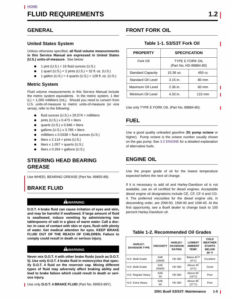
Use only TYPE E FORK OIL (Part No. 99884-80).
FUEL
Use a good quality unleaded gasoline (91 pump octane orhigher). Pump octane is the octane number usually shownon the gas pump. See 3.2 ENGINE for a detailed explanationof alternative fuels.
ENGINE OIL
Use the proper grade of oil for the lowest temperatureexpected before the next oil change.
If it is necessary to add oil and Harley-Davidson oil is notavailable, use an oil certified for diesel engines. Acceptablediesel engine oil designations include CE, CF, CF-4 and CG-4. The preferred viscosities for the diesel engine oils, indescending order, are 20W-50, 15W-40 and 10W-40. At thefirst opportunity, see a Buell dealer to change back to 100percent Harley-Davidson oil.
Table 1-1. S3/S3T Fork Oil
PROPERTY SPECFICATION
Fork OIl TYPE E FORK OIL (Part No. HD-99884-80)
Standard Capacity 15.36 oz. 450 cc
Standard Oil Level 3.15 in. 80 mm
Maximum Oil Level 2.36 in. 60 mm
Minimum Oil Level 4.33 in. 110 mm
Table 1-2. Recommended Oil Grades
HARLEY-DAVIDSON TYPE
VISCOSITYHARLEY-
DAVIDSON RATING
LOWESTAMBIENT
TEMP.
COLD WEATHER STARTS BELOW
50° F
H.D. Multi-GradeSAE
10W40HD 360
Below 40°F (4°C)
Excellent
H.D. Multi-GradeSAE
20W50HD 360
Above 40°
(4°C)Good
H.D. Regular HeavySAE50
HD 360Above 60°
(16°C)Poor
H.D. Extra HeavySAE60
HD 360Above 80°
(27°C)Poor
2001 Buell S3/S3T: Maintenance 1-5

HOME
PRIMARY DRIVE/TRANSMISSION FLUID
Use only SPORT-TRANS FLUID (Part No. 98854-96 quartsize or Part No. 98855-96 gallon size).
1-6 2001 Buell S3/S3T: Maintenance
2001 Bu
ell S3/S
3T: Main
tenan
ce1-7
HOME
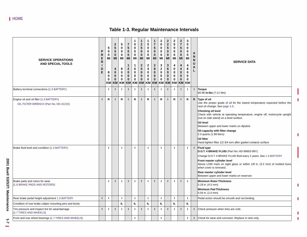
SERVICE DATA
Battery te
Engine oi
OIL FI f oil for the lowest temperature expected before thee 1-5.
perating temperature, engine off, motorcycle uprightlevel surface.
r marks on dipstick.
hange
turn after gasket contacts surface
Brake fluid(Part No. HD-99953-99Y)
FLUID fluid every 2 years. See 1.3 BATTERY
evel ght glass or within 1/8 in. (3.2 mm) of molded boss
vel r marks on reservoir.
Brake pad(1.6 BRAK
ess
s
Rear brak mooth and not binding.
Condition
Tire press(1.7 TIRE
es are cold.
Front and sion. Replace in sets only.
Table 1-3. Regular Maintenance Intervals
SERVICE OPERATIONS AND SPECIAL TOOLS
PRERIDE
500MI
800
KM
2500MI
4000
KM
5000MI
8000
KM
7500MI
12000
KM
10000MI
16000
KM
12500MI
20000
KM
15000MI
24000
KM
17500MI
28000
KM
20000MI
32000
KM
22500MI
36000
KM
25000MI
40000
KM
27500MI
44000
KM
30000MI
48000
KM
ANNUAL
rminal connections (1.3 BATTERY) I I I I I I I I I I I I I I Torque 60-96 in-lbs (7-11 Nm)
l and oil filter (1.3 BATTERY)
LTER WRENCH (Part No. HD-41215)
I R I R I R I R I R I R I R R Type of oilUse the proper grade onext oil change. See pag
Checking oil levelCheck with vehicle at o(not on side stand) on a
Oil levelBetween upper and lowe
Oil capacity with filter c2.0 quarts (1.89 liters)
Oil filterHand tighten filter 1/2-3/4
level and condition (1.3 BATTERY) I I I I I I I I Fluid typeD.O.T. 4 BRAKE FLUID
Change D.O.T. 4 BRAKE
Front master cylinder lAbove LOW mark on siwhen cover is removed.
Rear master cylinder leBetween upper and lowe
s and rotors for wearE PADS AND ROTORS)
I I I I I I I I I I I I I Minimum Rotor Thickn0.18 in. (4.5 mm)
Minimum Pad Thicknes0.04 in. (1.0 mm)
e pedal height adjustment 1.3 BATTERY I I I I I I I I Pedal action should be s
of rear brake caliper mounting pins and boots IL IL IL IL IL IL
ure and inspect tire for wear/damage S AND WHEELS)
I I I I I I I I I I I I I I I Check pressure when tir
rear wheel bearings (1.7 TIRES AND WHEELS) I I I I Check for wear and corro
2001 Bu
ell S3/S
3T: Main
tenan
ce1-8
HOME
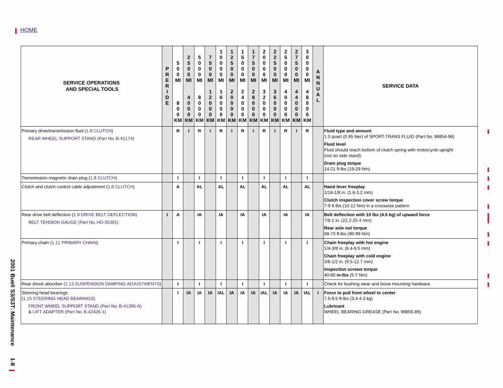
Primary d
REAR PORT-TRANS FLUID (Part No. 98854-96)
of clutch spring with motorcycle upright
Transmiss
Clutch an
r screw torque crosswise pattern
Rear drive
BELT T
lbs (4.5 kg) of upward force
Primary c engine
d engine
ue
Rear shoc and loose mounting hardware.
Steering h(1.15 STE
FRON& LIFT
el to center
ASE (Part No. 99855-89)
SERVICE DATA
rive/transmission fluid (1.8 CLUTCH)
WHEEL SUPPORT STAND (Part No. B-41174)
R I R I R I R I R I R I R Fluid type and amount1.0 quart (0.95 liter) of S
Fluid level Fluid should reach bottom(not on side stand).
Drain plug torque14-21 ft-lbs (19-29 Nm)
ion magnetic drain plug (1.8 CLUTCH) I I I I I I I
d clutch control cable adjustment (1.8 CLUTCH) A AL AL AL AL AL AL Hand lever freeplay 1/16-1/8 in. (1.6-3.2 mm)
Clutch inspection cove7-9 ft-lbs (10-12 Nm) in a
belt deflection (1.9 DRIVE BELT DEFLECTION)
ENSION GAUGE (Part No. HD-35381)
I A IA IA IA IA IA IA Belt deflection with 10 7/8-1 in. (22.2-25.4 mm)
Rear axle nut torque 68-73 ft-lbs (90-99 Nm)
hain (1.11 PRIMARY CHAIN) I I I I I I I Chain freeplay with hot1/4-3/8 in. (6.4-9.5 mm)
Chain freeplay with col3/8-1/2 in. (9.5-12.7 mm)
Inspection screws torq40-60 in-lbs (5-7 Nm)
k absorber (1.13 SUSPENSION DAMPING ADJUSTMENTS) I I I I I I I Check for bushing wear
ead bearingsERING HEAD BEARINGS)
T WHEEL SUPPORT STAND (Part No. B-41395-A) ADAPTER (Part No. B-42426-1)
I IA IA IA IAL IA IA IA IAL IA IA IA IAL I Force to pull front whe7.5-9.5 ft-lbs (3.4-4.3 kg)
LubricantWHEEL BEARING GRE
SERVICE OPERATIONS AND SPECIAL TOOLS
PRERIDE
500MI
800
KM
2500MI
4000
KM
5000MI
8000
KM
7500MI
12000
KM
10000MI
16000
KM
12500MI
20000
KM
15000MI
24000
KM
17500MI
28000
KM
20000MI
32000
KM
22500MI
36000
KM
25000MI
40000
KM
27500MI
44000
KM
30000MI
48000
KM
ANNUAL
1-92001 B
uell S
3/S3T: M
ainten
ance
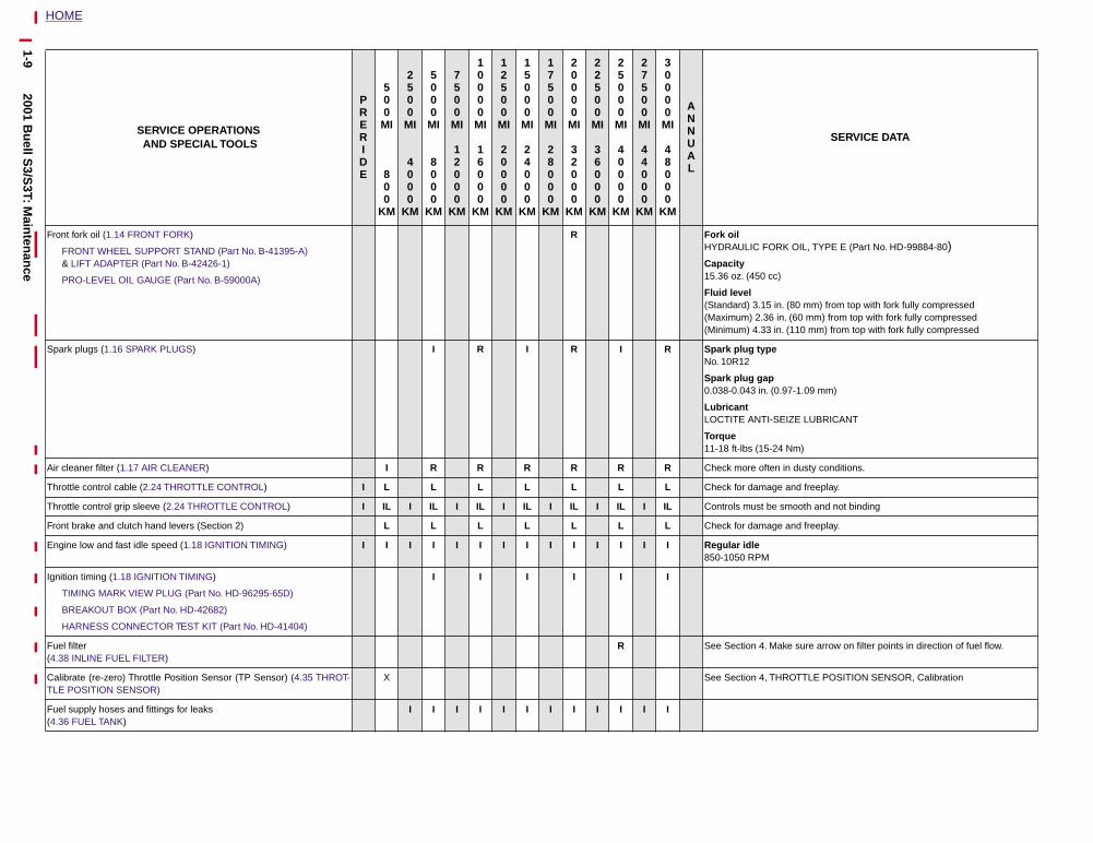
HOME
FORK OIL, TYPE E (Part No. HD-99884-80)
0 cc)
15 in. (80 mm) from top with fork fully compressed.36 in. (60 mm) from top with fork fully compressed33 in. (110 mm) from top with fork fully compressed
ype
ap in. (0.97-1.09 mm)
TI-SEIZE LUBRICANT
15-24 Nm)
often in dusty conditions.
mage and freeplay.
t be smooth and not binding
mage and freeplay.
M
4. Make sure arrow on filter points in direction of fuel flow.
4, THROTTLE POSITION SENSOR, Calibration
SERVICE DATA
Front fork oil (1.14 FRONT FORK)
FRONT WHEEL SUPPORT STAND (Part No. B-41395-A)& LIFT ADAPTER (Part No. B-42426-1)
PRO-LEVEL OIL GAUGE (Part No. B-59000A)
R Fork oilHYDRAULIC
Capacity15.36 oz. (45
Fluid level (Standard) 3.(Maximum) 2(Minimum) 4.
Spark plugs (1.16 SPARK PLUGS) I R I R I R Spark plug tNo. 10R12
Spark plug g0.038-0.043
Lubricant LOCTITE AN
Torque 11-18 ft-lbs (
Air cleaner filter (1.17 AIR CLEANER) I R R R R R R Check more
Throttle control cable (2.24 THROTTLE CONTROL) I L L L L L L L Check for da
Throttle control grip sleeve (2.24 THROTTLE CONTROL) I IL I IL I IL I IL I IL I IL I IL Controls mus
Front brake and clutch hand levers (Section 2) L L L L L L L Check for da
Engine low and fast idle speed (1.18 IGNITION TIMING) I I I I I I I I I I I I I I Regular idle850-1050 RP
Ignition timing (1.18 IGNITION TIMING)
TIMING MARK VIEW PLUG (Part No. HD-96295-65D)
BREAKOUT BOX (Part No. HD-42682)
HARNESS CONNECTOR TEST KIT (Part No. HD-41404)
I I I I I I
Fuel filter(4.38 INLINE FUEL FILTER)
R See Section
Calibrate (re-zero) Throttle Position Sensor (TP Sensor) (4.35 THROT-TLE POSITION SENSOR)
X See Section
Fuel supply hoses and fittings for leaks(4.36 FUEL TANK)
I I I I I I I I I I I I
SERVICE OPERATIONS AND SPECIAL TOOLS
PRERIDE
500MI
800
KM
2500MI
4000
KM
5000MI
8000
KM
7500MI
12000
KM
10000MI
16000
KM
12500MI
20000
KM
15000MI
24000
KM
17500MI
28000
KM
20000MI
32000
KM
22500MI
36000
KM
25000MI
40000
KM
27500MI
44000
KM
30000MI
48000
KM
ANNUAL
1-102001 B
uell S
3/S3T: M
ainten
ance
HOME
TI-SEIZE LUBRICANT
RING GREASE (Part No. HD99855-89)
ks and loose connections.
nded to inspect front and rear brake lines on D.O.T. 4 Brake sys- years and replace as required
nded to inspect front and rear master cylinder and caliper sealsrake systems every 2 years and replace as required.
SERVICE DATA
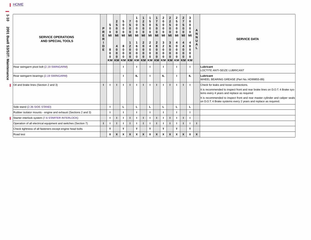
Rear swingarm pivot bolt (2.19 SWINGARM) I I I I I I LubricantLOCTITE AN
Rear swingarm bearings (2.19 SWINGARM) I IL I IL I IL LubricantWHEEL BEA
Oil and brake lines (Section 2 and 3) I I I I I I I I I I I I I I Check for lea
It is recommetems every 4
It is recommeon D.O.T. 4 B
Side stand (2.36 SIDE STAND) I L L L L L L
Rubber isolator mounts - engine and exhaust (Sections 2 and 3) I I I I I I I
Starter interlock system (7.6 STARTER INTERLOCK) I I I I I I I I I I I I I
Operation of all electrical equipment and switches (Section 7) I I I I I I I I I I I I I I I
Check tightness of all fasteners except engine head bolts T T T T T T T
Road test X X X X X X X X X X X X X X
SERVICE OPERATIONS AND SPECIAL TOOLS
PRERIDE
500MI
800
KM
2500MI
4000
KM
5000MI
8000
KM
7500MI
12000
KM
10000MI
16000
KM
12500MI
20000
KM
15000MI
24000
KM
17500MI
28000
KM
20000MI
32000
KM
22500MI
36000
KM
25000MI
40000
KM
27500MI
44000
KM
30000MI
48000
KM
ANNUAL
HOME
BATTERY 1.3
GENERAL
Buell motorcycle batteries are permanently sealed,maintenance-free, valve-regulated, lead/calcium and sulfuricacid batteries. The batteries are shipped pre-charged andready to be put into service. Do not attempt to open thesebatteries for any reason.
1WARNING1WARNING
All batteries contain electrolyte. Electrolyte is a sulfuricacid solution that is highly corrosive and can causesevere chemical burns. Avoid contact with skin, eyes,and clothing. Avoid spillage. Always wear protective faceshield, rubberized gloves and protective clothing whenworking with batteries. A warning label is attached to thetop of the battery. See Figures 1-1 and 1-2. Never removewarning label from battery. Failure to read and under-stand all precautions contained in warning label beforeperforming any service on batteries could result in deathor serious injury.
BATTERY TESTING
Voltmeter Test
See Table 1-4. The voltmeter test provides a general indicatorof battery condition. Check the voltage of the battery to verifythat it is in a 100% fully charged condition. If the open circuit(disconnected) voltage reading is below 12.6V, charge thebattery and then recheck the voltage after the battery has setfor one to two hours. If the voltage reading is 12.8V or above,perform the load test described in Section 7.
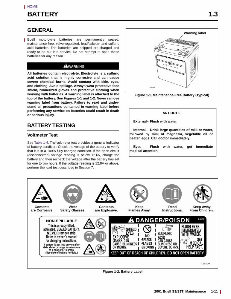
Figure 1-1. Maintenance-Free Battery (Typical)
M A D E I N U S AHA
RLEY-DA
VIDSO
N
MILWAU
KEE,
WI 5
3201
MADE I
N U.S.
A.
WARRAN
TY AN
D ADJUSTM
ENT POLIC
Y
This ba
ttery w
ill be re
placed
without c
harge
if found
to be
defect
ive in m
aterial
s or
workmans
hip 12
months
from da
te of
vehicle
purch
ase or
6 mont
hs from
date
of over
-the-co
unter p
urchas
e. After
6
months,
but w
ithin th
e 12 m
onths
of the
over-th
e-coun
ter pur
chase,
the ba
ttery w
ill
be rep
laced a
nd the
purch
aser ch
arged
only fo
r the p
eriod o
f owner
ship b
ased o
n
the reg
ular pr
ice at t
he tim
e of re
turn
prorate
d ver t
he num
ber of
months
of
warrant
y. This
warrant
y is no
t transf
erable
and is
voided
by the
use o
f rejuv
enators
,
improper
electro
lyte, ne
glect o
r abuse
.
PART
NO.
1
2
3
4
5
6
7
8
9
0
JA
FE
MA
AP
MY
JU
JY
AU
SE
OC
NO
DE
f1730x8x
Warning label
ANTIDOTE
External– Flush with water.
Internal– Drink large quantities of milk or water,followed by milk of magnesia, vegetable oil orbeaten eggs. Call doctor immediately.
Eyes– Flush with water, get immediatemedical attention.
Figure 1-2. Battery Label
Contentsare Corrosive.
WearSafety Glasses.
Contentsare Explosive.
KeepFlames Away.
ReadInstructions.
Keep AwayFrom Children.
f1733x8x
2001 Buell S3/S3T: Maintenance 1-11
HOME
DISCONNECTION AND REMOVAL
1. Remove seat. See 2.35 SEAT.
1WARNING1WARNING
To protect against shock and accidental start-up of vehi-cle, disconnect the negative battery cable before pro-ceeding. Inadequate safety precautions could result indeath or serious injury.
1WARNING1WARNING
Always disconnect the negative battery cable first. If thepositive cable should contact ground with the negativecable installed, the resulting sparks may cause a batteryexplosion which could result in death or serious injury.
2. Unthread bolt and remove battery negative cable (black)from battery negative (-) terminal.
3. Unthread bolt and remove battery positive cable (red)from battery positive (+) terminal.
4. Remove battery strap locknut (metric). Unhook batterystrap from frame near negative terminal.
5. Cut any cable straps holding oxygen sensor connector tobattery.
6. Remove battery from right side.
CLEANING AND INSPECTION
1. Battery top must be clean and dry. Dirt and electrolyte ontop of the battery can cause battery to self-discharge.Clean battery top with a solution of baking soda (sodiumbicarbonate) and water (5 teaspoons baking soda perquart or liter of water). When the solution stops bubbling,rinse off the battery with clean water.
2. Clean cable connectors and battery terminals using awire brush or sandpaper. Remove any oxidation.
3. Inspect the battery screws, clamps and cables for break-age, loose connections and corrosion. Clean clamps.
4. Check the battery posts for melting or damage causedby overtightening.
5. Inspect the battery for discoloration, raised top or awarped or distorted case, which might indicate that thebattery has been frozen, overheated or overcharged.
6. Inspect the battery case for cracks or leaks.
STORAGE
1WARNING1WARNING
Always store batteries where they cannot be reached bychildren. Contact with the battery’s sulfuric acid couldresult in death or serious injury.
CAUTION
The electrolyte in a discharged battery will freeze ifexposed to freezing temperatures. Freezing may crackthe battery case and buckle battery plates.
If the motorcycle will not be operated for several months,such as during the winter season, remove the battery fromthe motorcycle and fully charge. See CHARGING BATTERY,Section 7.
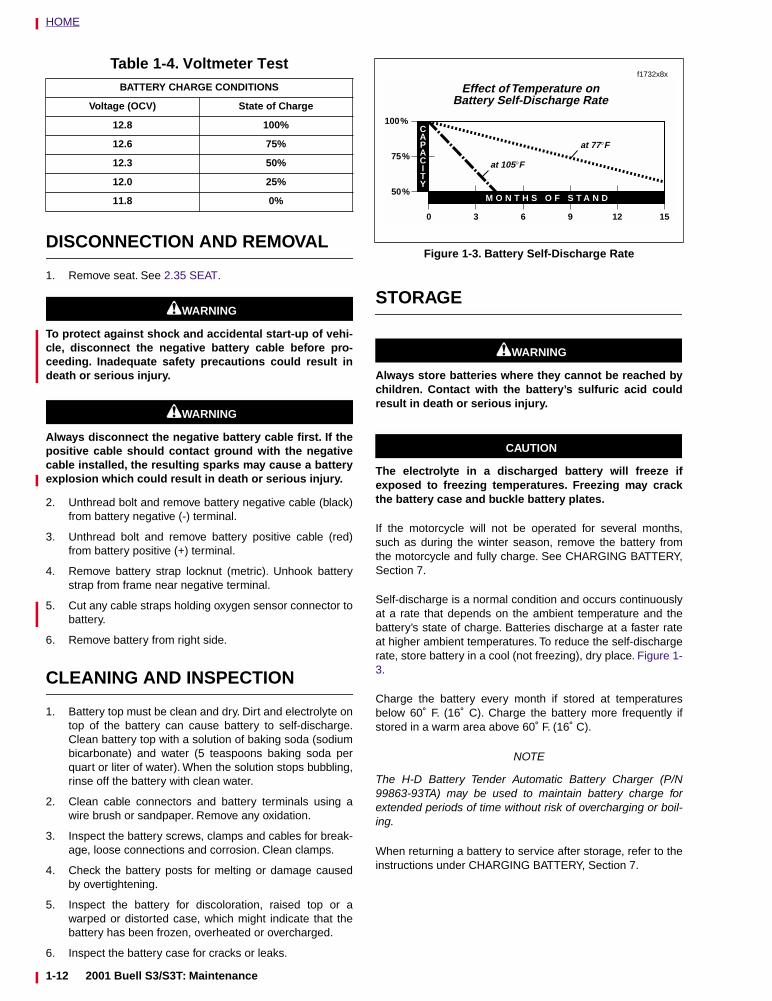
Self-discharge is a normal condition and occurs continuouslyat a rate that depends on the ambient temperature and thebattery’s state of charge. Batteries discharge at a faster rateat higher ambient temperatures. To reduce the self-dischargerate, store battery in a cool (not freezing), dry place. Figure 1-3.
Charge the battery every month if stored at temperaturesbelow 60˚ F. (16˚ C). Charge the battery more frequently ifstored in a warm area above 60˚ F. (16˚ C).
NOTE
The H-D Battery Tender Automatic Battery Charger (P/N99863-93TA) may be used to maintain battery charge forextended periods of time without risk of overcharging or boil-ing.
When returning a battery to service after storage, refer to theinstructions under CHARGING BATTERY, Section 7.
Table 1-4. Voltmeter TestBATTERY CHARGE CONDITIONS
Voltage (OCV) State of Charge
12.8 100%
12.6 75%
12.3 50%
12.0 25%
11.8 0%
Figure 1-3. Battery Self-Discharge Rate
3 6 9 12 15
50%
75%
100%
M O N T H S O F S T A N D
CAPACITY
0
at 105°F
at 77°F
Effect of Temperature onBattery Self-Discharge Rate
f1732x8x
1-12 2001 Buell S3/S3T: Maintenance
HOME
BATTERY INSTALLATION AND CONNECTION
1. Place the fully charged battery into the battery box, ter-minal side forward.
CAUTION
Connect the cables to the correct battery terminals ordamage to the motorcycle electrical system will occur.
1WARNING1WARNING
Always connect the positive battery cable first. If thepositive cable should contact ground with the negativecable installed, the resulting sparks may cause a batteryexplosion which could result in death or serious injury.
CAUTION
Overtightening bolts can damage battery terminals.
2. Insert bolt through battery positive cable (red) intothreaded hole of battery positive (+) terminal. Tightenbolt to 60-96 in-lbs (7-11 Nm).
3. Insert bolt through battery negative cable (black) intothreaded hole of battery negative (-) terminal. Tightenbolt to 60-96 in-lbs (7-11 Nm).
4. Apply a light coat of petroleum jelly or corrosion retar-dant material to both battery terminals.
5. Install battery strap.
a. Insert tab on right side of battery tray. Place batterystrap around top side of battery.
b. Hook edge of strap into frame tab.
c. Insert threaded shaft on strap through frame tab.
d. Install battery strap locknut on threaded shaft.Tighten to 40 in-lbs (4.5 Nm).
6. Apply light coat of petroleum jelly or corrosion-retardantmaterial to both battery terminals.
7. Secure oxygen sensor connector with new cable straps.
8. Install seat. See 2.35 SEAT.
2001 Buell S3/S3T: Maintenance 1-13
HOME
ENGINE LUBRICATION SYSTEM 1.4
CHECKING ENGINE OIL LEVEL
Check engine oil level:
● At least once every 500 miles (800 km).
● At every scheduled service interval.
NOTEIf engine uses more oil than normal or if vehicle is operatedunder harsh conditions, check oil more frequently.
When checking or changing engine oil:
● Warm vehicle to normal operating temperature.
● Turn engine off.
● Hold motorcycle upright (not leaning on side stand) on alevel surface.
1. Remove seat. See 2.35 SEAT.
2. See Figure 1-5. Remove filler cap/dipstick from oil tank.Wipe dipstick clean.
3. Install filler cap onto oil tank. Make sure cap is fullyseated on tank.
CAUTION
Do not switch oil brands indiscriminately because someoils interact chemically when mixed. Use of inferior oilsor non-detergent oils can damage the engine.
4. Remove filler cap again and check oil level on dipstick.
a. Oil level should be between lower and upper dipsticklevel marks.
b. If oil level in tank is below lower mark of dipstick, addoil to tank.
c. Install filler cap/dipstick.
Recommended viscosity depends upon ambient temper-ature. See Table 1-4. If it is necessary to add oil and Har-ley-Davidson oil is not available, use an oil certified fordiesel engines. Acceptable diesel engine oil designa-tions include CE, CF, CF-4 and CG-4. The preferred vis-cosities for the diesel engine oils, in descending order,are 20W-50, 15W-40 and 10W-40. At the first opportu-nity, see a Buell dealer to change back to 100 percentHarley-Davidson oil.
1WARNING1WARNING
After installing seat, pull upward on front of seat to besure it is locked in position. If seat is loose, it could shiftduring vehicle operation and startle the rider, causingloss of control which could result in death or seriousinjury.
5. Install seat. See 2.35 SEAT.
CHANGING ENGINE OIL AND FILTER
Change engine oil:
● At the 500 mile (800 km) service interval.
● At every 5000 mile (8000 km) service interval thereafter.
● When storing or removing the motorcycle for the season.
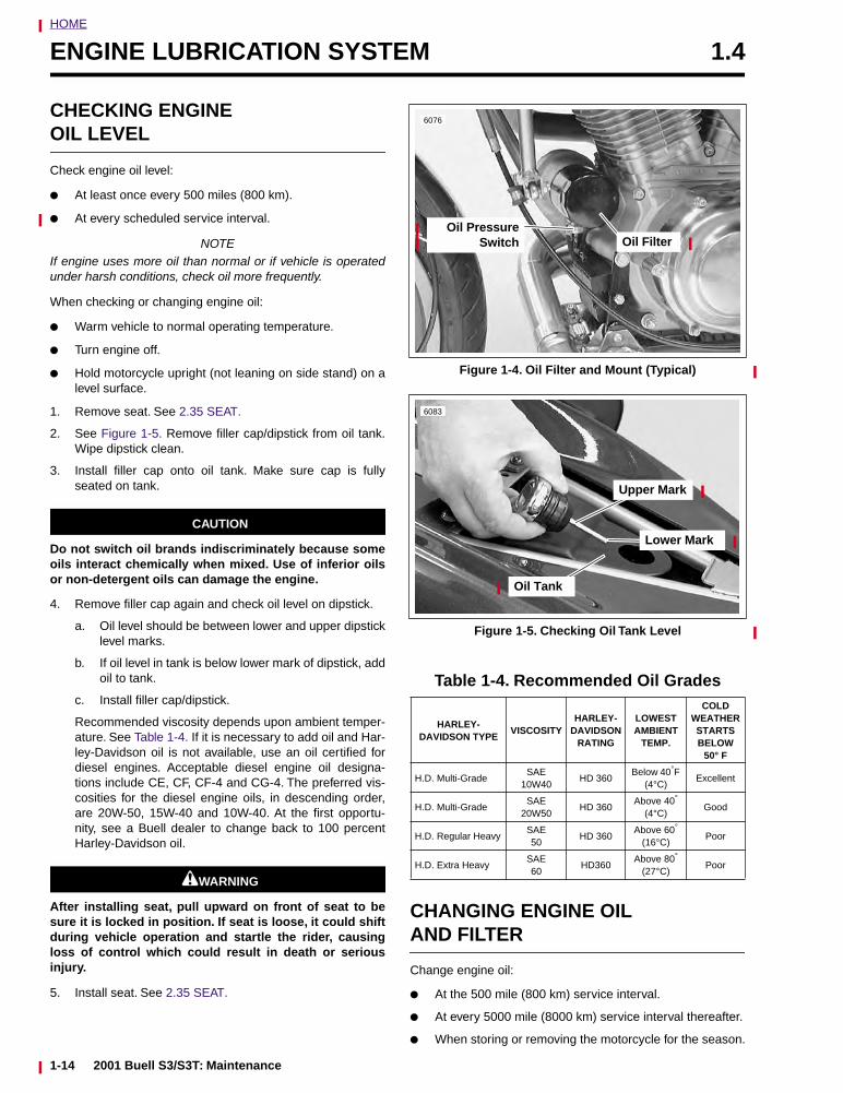
Figure 1-4. Oil Filter and Mount (Typical)
Figure 1-5. Checking Oil Tank Level
Table 1-4. Recommended Oil Grades
HARLEY-DAVIDSON TYPE
VISCOSITYHARLEY-
DAVIDSON RATING
LOWESTAMBIENT
TEMP.
COLD WEATHER STARTS BELOW
50° F
H.D. Multi-GradeSAE
10W40HD 360
Below 40°F (4°C)
Excellent
H.D. Multi-GradeSAE
20W50HD 360
Above 40°
(4°C)Good
H.D. Regular HeavySAE50
HD 360Above 60°
(16°C)Poor
H.D. Extra HeavySAE60
HD360Above 80°
(27°C)Poor
6076
Oil FilterOil Pressure
Switch
Lower Mark
Upper Mark
6083
Oil Tank
1-14 2001 Buell S3/S3T: Maintenance
HOME
NOTE
The colder the weather, the shorter the recommended oilchange interval. A vehicle used only for short runs in coldweather must have the engine oil drained more frequently.
1. Place a suitable container under the motorcycle.
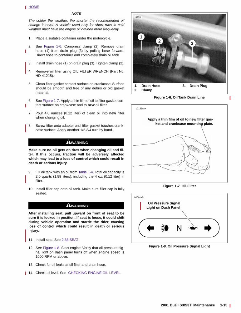
2. See Figure 1-6. Compress clamp (2). Remove drainhose (1) from drain plug (3) by pulling hose forward.Direct hose to container and completely drain oil tank.
3. Install drain hose (1) on drain plug (3). Tighten clamp (2).
4. Remove oil filter using OIL FILTER WRENCH (Part No.HD-41215).
5. Clean filter gasket contact surface on crankcase. Surfaceshould be smooth and free of any debris or old gasketmaterial.
6. See Figure 1-7. Apply a thin film of oil to filter gasket con-tact surface on crankcase and to new oil filter.
7. Pour 4.0 ounces (0.12 liter) of clean oil into new filterwhen changing oil.
8. Screw filter onto adapter until filter gasket touches crank-case surface. Apply another 1/2-3/4 turn by hand.
1WARNING1WARNING
Make sure no oil gets on tires when changing oil and fil-ter. If this occurs, traction will be adversely affectedwhich may lead to a loss of control which could result indeath or serious injury.
9. Fill oil tank with an oil from Table 1-4. Total oil capacity is2.0 quarts (1.89 liters); including the 4 oz. (0.12 liter) infilter.
10. Install filler cap onto oil tank. Make sure filler cap is fullyseated.
1WARNING1WARNING
After installing seat, pull upward on front of seat to besure it is locked in position. If seat is loose, it could shiftduring vehicle operation and startle the rider, causingloss of control which could result in death or seriousinjury.
11. Install seat. See 2.35 SEAT.
12. See Figure 1-8. Start engine. Verify that oil pressure sig-nal light on dash panel turns off when engine speed is1000 RPM or above.
13. Check for oil leaks at oil filter and drain hose.
14. Check oil level. See CHECKING ENGINE OIL LEVEL.
Figure 1-6. Oil Tank Drain Line
Figure 1-7. Oil Filter
Figure 1-8. Oil Pressure Signal Light
1. Drain Hose2. Clamp
3. Drain Plug
1
6216
2 3
b0138aox
Apply a thin film of oil to new filter gas-ket and crankcase mounting plate.
Oil Pressure SignalLight on Dash Panel
b0091x7x
2001 Buell S3/S3T: Maintenance 1-15
HOME
BRAKES 1.5
GENERAL
1WARNING1WARNING
D.O.T. 4 brake fluid can cause irritation of eyes and skin,and may be harmful if swallowed. If large amount of fluidis swallowed, induce vomiting by administering twotablespoons of salt in a glass of warm water. Call a doc-tor. In case of contact with skin or eyes, flush with plentyof water. Get medical attention for eyes. KEEP BRAKEFLUID OUT OF THE REACH OF CHILDREN. Failure tocomply could result in death or serious injury.
CAUTION
D.O.T. 4 brake fluid will damage painted surfaces itcomes in contact with. Always use caution and protectpainted surfaces from spills whenever brake work is per-formed. Failure to comply may result in cosmetic dam-age.
Check brake fluid level and condition:
● At the 500 mile (800 km) service interval.
● At every 5000 mile (8000 km) service interval thereafter.
● When storing or removing the motorcycle for the season.
Replace D.O.T. 4 BRAKE FLUID:
● Every 2 years.
Front brake hand lever and rear brake foot pedal must have afirm feel when brakes are applied. If not, bleed system asdescribed.
Inspect front and rear brake lines and replace as required:
● Every 4 years.
Inspect caliper and master cylinder seals and replace asrequired:
● Every 2 years.
BLEEDING BRAKES
1WARNING1WARNING
D.O.T. 4 brake fluid can cause irritation of eyes and skin,and may be harmful if swallowed. If large amount of fluidis swallowed, induce vomiting by administering twotablespoons of salt in a glass of warm water. Call a doc-tor. In case of contact with skin or eyes, flush with plentyof water. Get medical attention for eyes. KEEP BRAKEFLUID OUT OF THE REACH OF CHILDREN. Failure tocomply could result in death or serious injury.
1WARNING1WARNING
Never mix D.O.T. 4 with other brake fluids (such as D.O.T.5). Use only D.O.T. 4 brake fluid in motorcycles that spec-ify D.O.T. 4 fluid on the reservoir cap. Mixing differenttypes of fluid may adversely affect braking ability and
lead to brake failure which could result in death or seri-ous injury.
1WARNING1WARNING
Use only fresh, uncontaminated D.O.T. 4 fluid. Cans offluid that have been opened may have been contami-nated by moisture in the air or dirt. Use of contaminatedbrake fluid may adversely affect braking ability and leadto brake failure which could result in death or seriousinjury.
1WARNING1WARNING
Use only new black banjo washers (See Parts Catalog forPart No.) with D.O.T. 4 brake fluid. Earlier silver banjowashers are not compatible with D.O.T. 4 fluid and willnot seal properly over time. Failure to comply mayadversely affect braking ability and lead to brake failurewhich could result in death or serious injury.
CAUTION
D.O.T. 4 brake fluid will damage painted surfaces itcomes in contact with. Always use caution and protectpainted surfaces from spills whenever brake work is per-formed. Failure to comply may result in cosmetic dam-age.
NOTEHydraulic brake fluid bladder-type pressure equipment canbe used to fill the brake master cylinder through the bleedervalve if master cylinder reservoir cover is removed to preventpressurization.
1-16 2001 Buell S3/S3T: Maintenance
HOME
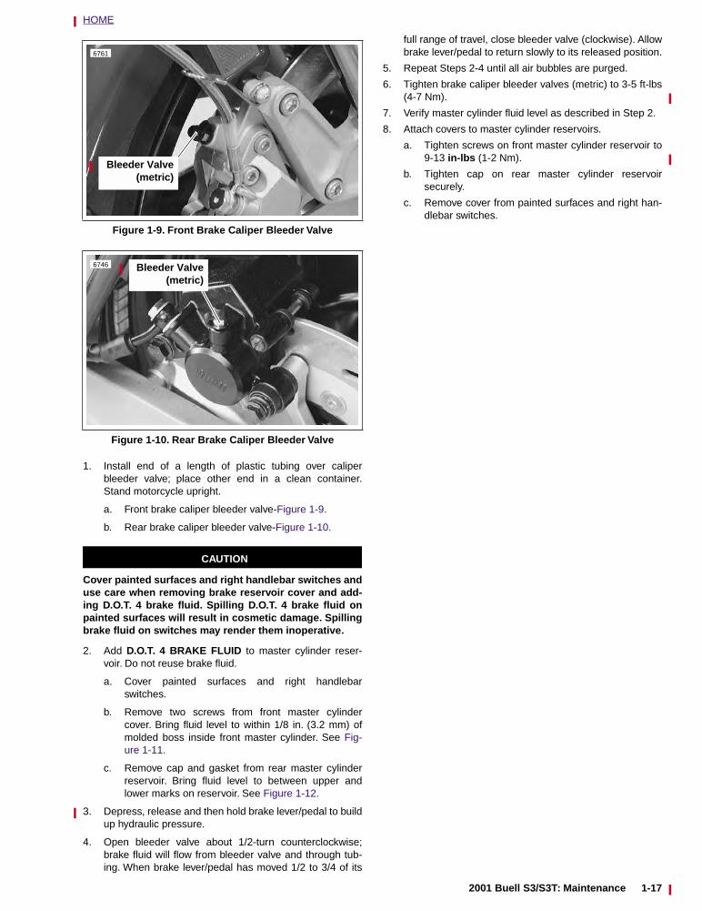
1. Install end of a length of plastic tubing over caliperbleeder valve; place other end in a clean container.Stand motorcycle upright.
a. Front brake caliper bleeder valve-Figure 1-9.
b. Rear brake caliper bleeder valve-Figure 1-10.
CAUTION
Cover painted surfaces and right handlebar switches anduse care when removing brake reservoir cover and add-ing D.O.T. 4 brake fluid. Spilling D.O.T. 4 brake fluid onpainted surfaces will result in cosmetic damage. Spillingbrake fluid on switches may render them inoperative.
2. Add D.O.T. 4 BRAKE FLUID to master cylinder reser-voir. Do not reuse brake fluid.
a. Cover painted surfaces and right handlebarswitches.
b. Remove two screws from front master cylindercover. Bring fluid level to within 1/8 in. (3.2 mm) ofmolded boss inside front master cylinder. See Fig-ure 1-11.
c. Remove cap and gasket from rear master cylinderreservoir. Bring fluid level to between upper andlower marks on reservoir. See Figure 1-12.
3. Depress, release and then hold brake lever/pedal to buildup hydraulic pressure.
4. Open bleeder valve about 1/2-turn counterclockwise;brake fluid will flow from bleeder valve and through tub-ing. When brake lever/pedal has moved 1/2 to 3/4 of its
full range of travel, close bleeder valve (clockwise). Allowbrake lever/pedal to return slowly to its released position.
5. Repeat Steps 2-4 until all air bubbles are purged.
6. Tighten brake caliper bleeder valves (metric) to 3-5 ft-lbs(4-7 Nm).
7. Verify master cylinder fluid level as described in Step 2.
8. Attach covers to master cylinder reservoirs.
a. Tighten screws on front master cylinder reservoir to9-13 in-lbs (1-2 Nm).
b. Tighten cap on rear master cylinder reservoirsecurely.
c. Remove cover from painted surfaces and right han-dlebar switches.
Figure 1-9. Front Brake Caliper Bleeder Valve
Figure 1-10. Rear Brake Caliper Bleeder Valve
6761
Bleeder Valve(metric)
6746 Bleeder Valve(metric)
2001 Buell S3/S3T: Maintenance 1-17
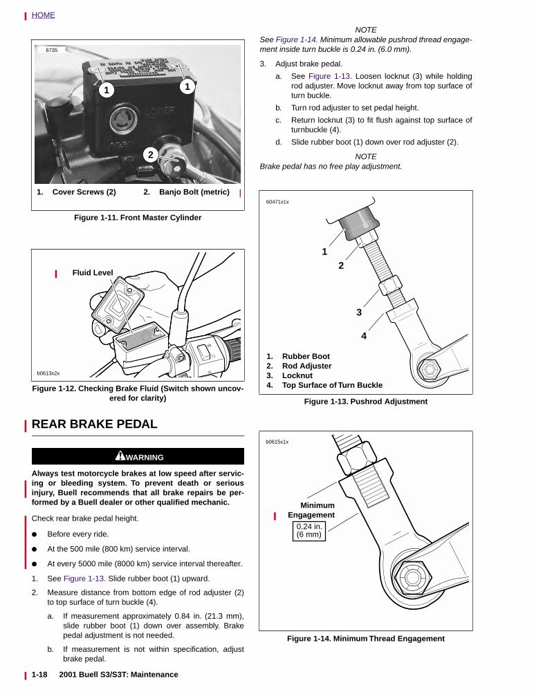
HOME
REAR BRAKE PEDAL
1WARNING1WARNING
Always test motorcycle brakes at low speed after servic-ing or bleeding system. To prevent death or seriousinjury, Buell recommends that all brake repairs be per-formed by a Buell dealer or other qualified mechanic.
Check rear brake pedal height.
● Before every ride.
● At the 500 mile (800 km) service interval.
● At every 5000 mile (8000 km) service interval thereafter.
1. See Figure 1-13. Slide rubber boot (1) upward.
2. Measure distance from bottom edge of rod adjuster (2)to top surface of turn buckle (4).
a. If measurement approximately 0.84 in. (21.3 mm),slide rubber boot (1) down over assembly. Brakepedal adjustment is not needed.
b. If measurement is not within specification, adjustbrake pedal.
NOTESee Figure 1-14. Minimum allowable pushrod thread engage-ment inside turn buckle is 0.24 in. (6.0 mm).
3. Adjust brake pedal.
a. See Figure 1-13. Loosen locknut (3) while holdingrod adjuster. Move locknut away from top surface ofturn buckle.
b. Turn rod adjuster to set pedal height.
c. Return locknut (3) to fit flush against top surface ofturnbuckle (4).
d. Slide rubber boot (1) down over rod adjuster (2).
NOTEBrake pedal has no free play adjustment.
Figure 1-11. Front Master Cylinder
Figure 1-12. Checking Brake Fluid (Switch shown uncov-ered for clarity)
6735
1
2
1
1. Cover Screws (2) 2. Banjo Bolt (metric)
Fluid Level
b0613x2x
Figure 1-13. Pushrod Adjustment
Figure 1-14. Minimum Thread Engagement
b0471x1x
1. Rubber Boot2. Rod Adjuster3. Locknut4. Top Surface of Turn Buckle
12
3
4
MinimumEngagement
b0615x1x
0.24 in.(6 mm)
1-18 2001 Buell S3/S3T: Maintenance
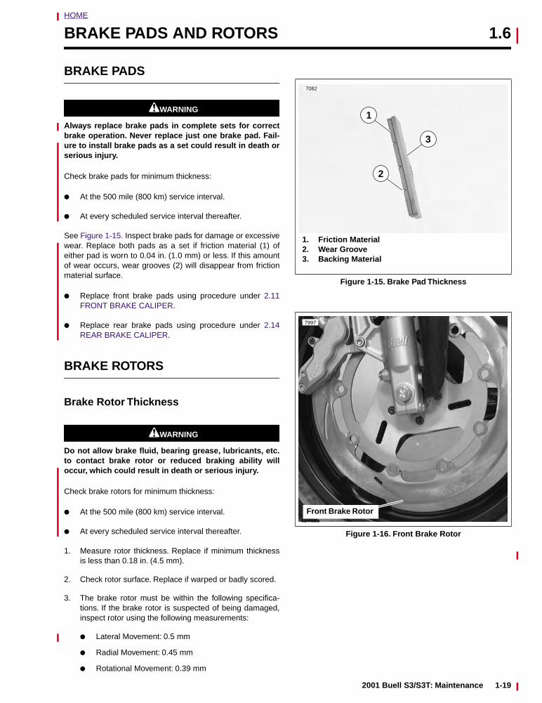
HOME
BRAKE PADS AND ROTORS 1.6
BRAKE PADS
1WARNING1WARNING
Always replace brake pads in complete sets for correctbrake operation. Never replace just one brake pad. Fail-ure to install brake pads as a set could result in death orserious injury.
Check brake pads for minimum thickness:
● At the 500 mile (800 km) service interval.
● At every scheduled service interval thereafter.
See Figure 1-15. Inspect brake pads for damage or excessivewear. Replace both pads as a set if friction material (1) ofeither pad is worn to 0.04 in. (1.0 mm) or less. If this amountof wear occurs, wear grooves (2) will disappear from frictionmaterial surface.
● Replace front brake pads using procedure under 2.11FRONT BRAKE CALIPER.
● Replace rear brake pads using procedure under 2.14REAR BRAKE CALIPER.
BRAKE ROTORS
Brake Rotor Thickness
1WARNING1WARNING
Do not allow brake fluid, bearing grease, lubricants, etc.to contact brake rotor or reduced braking ability willoccur, which could result in death or serious injury.
Check brake rotors for minimum thickness:
● At the 500 mile (800 km) service interval.
● At every scheduled service interval thereafter.
1. Measure rotor thickness. Replace if minimum thicknessis less than 0.18 in. (4.5 mm).
2. Check rotor surface. Replace if warped or badly scored.
3. The brake rotor must be within the following specifica-tions. If the brake rotor is suspected of being damaged,inspect rotor using the following measurements:
● Lateral Movement: 0.5 mm
● Radial Movement: 0.45 mm
● Rotational Movement: 0.39 mm
Figure 1-15. Brake Pad Thickness
Figure 1-16. Front Brake Rotor
1. Friction Material2. Wear Groove3. Backing Material
1
7082
2
3
b6738a
Front Brake Rotor
7997
2001 Buell S3/S3T: Maintenance 1-19
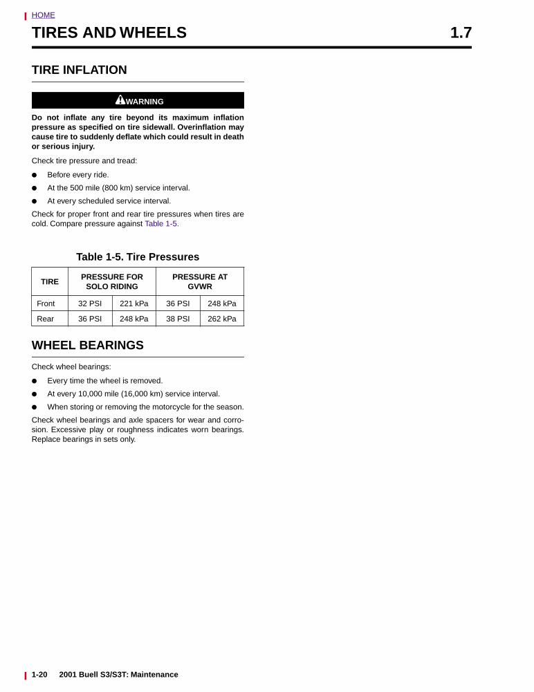
HOME
TIRES AND WHEELS 1.7
TIRE INFLATION
1WARNING1WARNING
Do not inflate any tire beyond its maximum inflationpressure as specified on tire sidewall. Overinflation maycause tire to suddenly deflate which could result in deathor serious injury.
Check tire pressure and tread:
● Before every ride.
● At the 500 mile (800 km) service interval.
● At every scheduled service interval.
Check for proper front and rear tire pressures when tires arecold. Compare pressure against Table 1-5.
WHEEL BEARINGS
Check wheel bearings:
● Every time the wheel is removed.
● At every 10,000 mile (16,000 km) service interval.
● When storing or removing the motorcycle for the season.
Check wheel bearings and axle spacers for wear and corro-sion. Excessive play or roughness indicates worn bearings.Replace bearings in sets only.
Table 1-5. Tire Pressures
TIRE PRESSURE FOR
SOLO RIDING PRESSURE AT
GVWR
Front 32 PSI 221 kPa 36 PSI 248 kPa
Rear 36 PSI 248 kPa 38 PSI 262 kPa
1-20 2001 Buell S3/S3T: Maintenance
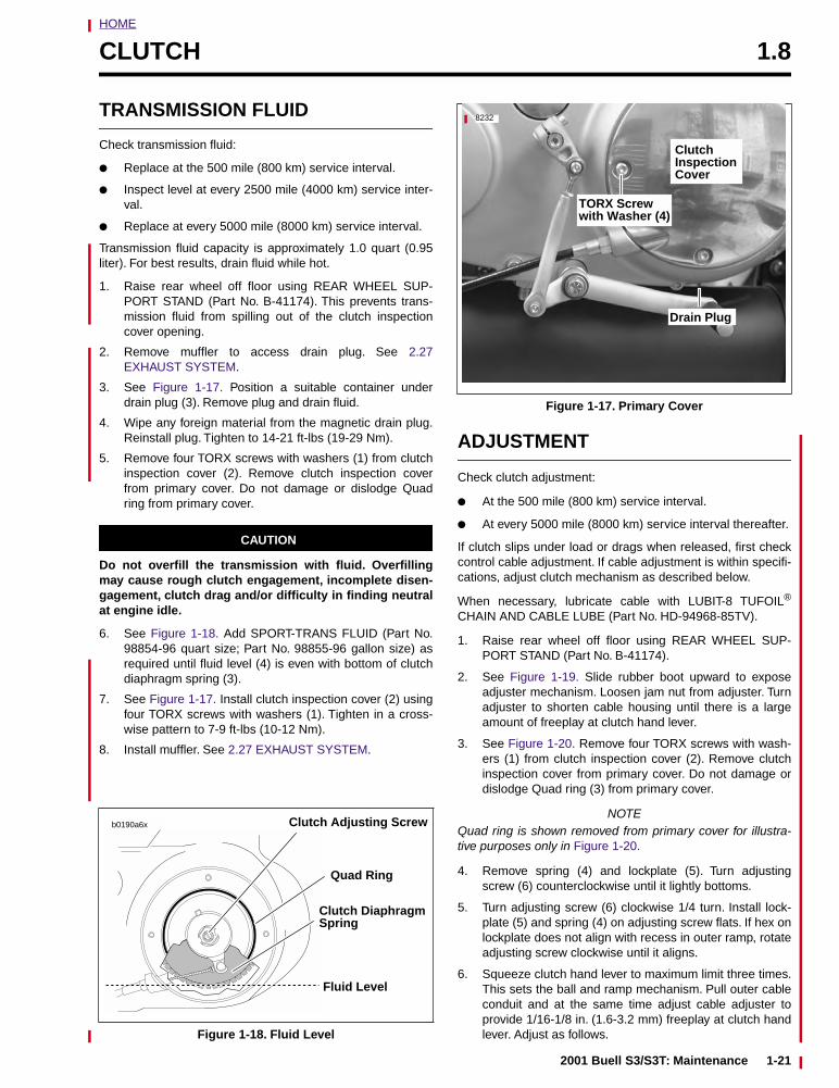
HOME
CLUTCH 1.8
TRANSMISSION FLUID
Check transmission fluid:
● Replace at the 500 mile (800 km) service interval.
● Inspect level at every 2500 mile (4000 km) service inter-val.
● Replace at every 5000 mile (8000 km) service interval.
Transmission fluid capacity is approximately 1.0 quart (0.95liter). For best results, drain fluid while hot.
1. Raise rear wheel off floor using REAR WHEEL SUP-PORT STAND (Part No. B-41174). This prevents trans-mission fluid from spilling out of the clutch inspectioncover opening.
2. Remove muffler to access drain plug. See 2.27EXHAUST SYSTEM.
3. See Figure 1-17. Position a suitable container underdrain plug (3). Remove plug and drain fluid.
4. Wipe any foreign material from the magnetic drain plug.Reinstall plug. Tighten to 14-21 ft-lbs (19-29 Nm).
5. Remove four TORX screws with washers (1) from clutchinspection cover (2). Remove clutch inspection coverfrom primary cover. Do not damage or dislodge Quadring from primary cover.
CAUTION
Do not overfill the transmission with fluid. Overfillingmay cause rough clutch engagement, incomplete disen-gagement, clutch drag and/or difficulty in finding neutralat engine idle.
6. See Figure 1-18. Add SPORT-TRANS FLUID (Part No.98854-96 quart size; Part No. 98855-96 gallon size) asrequired until fluid level (4) is even with bottom of clutchdiaphragm spring (3).
7. See Figure 1-17. Install clutch inspection cover (2) usingfour TORX screws with washers (1). Tighten in a cross-wise pattern to 7-9 ft-lbs (10-12 Nm).
8. Install muffler. See 2.27 EXHAUST SYSTEM.
ADJUSTMENT
Check clutch adjustment:
● At the 500 mile (800 km) service interval.
● At every 5000 mile (8000 km) service interval thereafter.
If clutch slips under load or drags when released, first checkcontrol cable adjustment. If cable adjustment is within specifi-cations, adjust clutch mechanism as described below.
When necessary, lubricate cable with LUBIT-8 TUFOIL®
CHAIN AND CABLE LUBE (Part No. HD-94968-85TV).
1. Raise rear wheel off floor using REAR WHEEL SUP-PORT STAND (Part No. B-41174).
2. See Figure 1-19. Slide rubber boot upward to exposeadjuster mechanism. Loosen jam nut from adjuster. Turnadjuster to shorten cable housing until there is a largeamount of freeplay at clutch hand lever.
3. See Figure 1-20. Remove four TORX screws with wash-ers (1) from clutch inspection cover (2). Remove clutchinspection cover from primary cover. Do not damage ordislodge Quad ring (3) from primary cover.
NOTEQuad ring is shown removed from primary cover for illustra-tive purposes only in Figure 1-20.
4. Remove spring (4) and lockplate (5). Turn adjustingscrew (6) counterclockwise until it lightly bottoms.
5. Turn adjusting screw (6) clockwise 1/4 turn. Install lock-plate (5) and spring (4) on adjusting screw flats. If hex onlockplate does not align with recess in outer ramp, rotateadjusting screw clockwise until it aligns.
6. Squeeze clutch hand lever to maximum limit three times.This sets the ball and ramp mechanism. Pull outer cableconduit and at the same time adjust cable adjuster toprovide 1/16-1/8 in. (1.6-3.2 mm) freeplay at clutch handlever. Adjust as follows.Figure 1-18. Fluid Level
b0190a6x
Fluid Level
Clutch DiaphragmSpring
Quad Ring
Clutch Adjusting Screw
Figure 1-17. Primary Cover
8232
Drain Plug
Clutch
CoverInspection
TORX Screwwith Washer (4)
2001 Buell S3/S3T: Maintenance 1-21
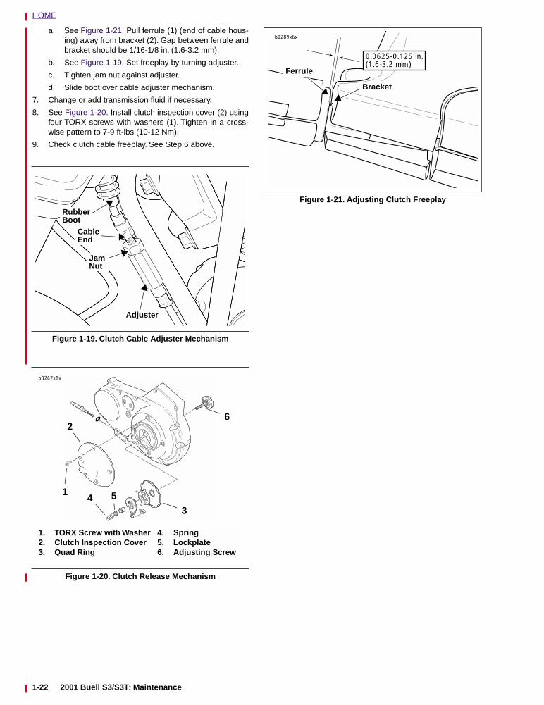
HOME
a. See Figure 1-21. Pull ferrule (1) (end of cable hous-ing) away from bracket (2). Gap between ferrule andbracket should be 1/16-1/8 in. (1.6-3.2 mm).
b. See Figure 1-19. Set freeplay by turning adjuster.
c. Tighten jam nut against adjuster.
d. Slide boot over cable adjuster mechanism.
7. Change or add transmission fluid if necessary.
8. See Figure 1-20. Install clutch inspection cover (2) usingfour TORX screws with washers (1). Tighten in a cross-wise pattern to 7-9 ft-lbs (10-12 Nm).
9. Check clutch cable freeplay. See Step 6 above.
Figure 1-19. Clutch Cable Adjuster Mechanism
Figure 1-20. Clutch Release Mechanism
Rubber Boot
Cable End
Jam Nut
Adjuster
1. TORX Screw with Washer2. Clutch Inspection Cover3. Quad Ring
4 51
2
3
6
4. Spring5. Lockplate6. Adjusting Screw
b0267x8x
Figure 1-21. Adjusting Clutch Freeplay
b0289x6x
Bracket
Ferrule
0.0625-0.125 in.(1.6-3.2 mm)
1-22 2001 Buell S3/S3T: Main
tenance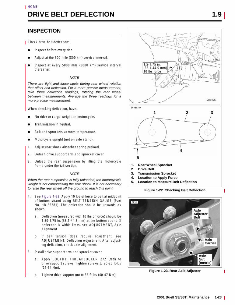
HOME
DRIVE BELT DEFLECTION 1.9
INSPECTION
Check drive belt deflection:
● Inspect before every ride.
● Adjust at the 500 mile (800 km) service interval.
● Inspect at every 5000 mile (8000 km) service intervalthereafter.
NOTE
There are tight and loose spots during rear wheel rotationthat affect belt deflection. For a more precise measurement,take three deflection readings, rotating the rear wheelbetween measurements. Average the three readings for amore precise measurement.
When checking deflection, have:
● No rider or cargo weight on motorcycle.
● Transmission in neutral.
● Belt and sprockets at room temperature.
● Motorcycle upright (not on side stand).
1. Adjust rear shock absorber spring preload.
2. Detach drive support arm and sprocket cover.
3. Unload the rear suspension by lifting the motorcycleframe under the tail section.
NOTE
When the rear suspension is fully unloaded, the motorcycle’sweight is not compressing the rear shock. It is not necessaryto raise the rear wheel off the ground to reach this point.
4. See Figure 1-22. Apply 10 lbs of force to belt at midpointof bottom strand using BELT TENSION GAUGE (PartNo. HD-35381). The deflection should be upwards asshown.
a. Deflection (measured with 10 lbs of force) should be1.50-1.75 in. (38.1-44.5 mm) at the bottom strand. Ifdeflection is within limits, see ADJUSTMENT, AxleAlignment.
b. If belt tension does require adjustment, seeADJUSTMENT, Deflection Adjustment. After adjust-ing deflection, check axle alignment.
5. Install drive support arm and sprocket cover.
a. Apply LOCTITE THREADLOCKER 272 (red) todrive support screws. Tighten screws to 20-25 ft-lbs(27-34 Nm).
b. Tighten drive support nut to 35 ft-lbs (40-47 Nm).
Figure 1-22. Checking Belt Deflection
Figure 1-23. Rear Axle Adjuster
b0086a6x
2
1. Rear Wheel Sprocket2. Drive Belt3. Transmission Sprocket4. Location to Apply Force5. Location to Measure Belt Deflection
31
4
5
b0609x6x
1.5-1.75 in.(38.1-44.5 mm)10 lbs force
6851
Axle Nut(metric)
Axle Carrier
Axle AdjusterBolt
2001 Buell S3/S3T: Maintenance 1-23
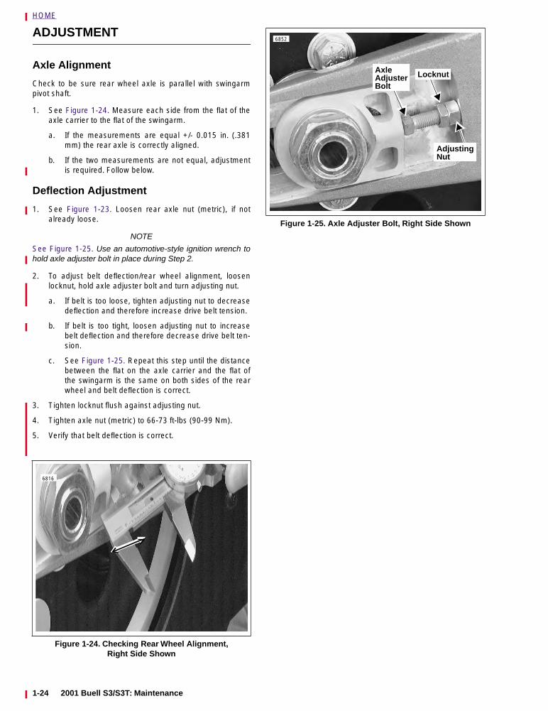
HOME
ADJUSTMENT
Axle Alignment
Check to be sure rear wheel axle is parallel with swingarmpivot shaft.
1. See Figure 1-24. Measure each side from the flat of theaxle carrier to the flat of the swingarm.
a. If the measurements are equal +/- 0.015 in. (.381mm) the rear axle is correctly aligned.
b. If the two measurements are not equal, adjustmentis required. Follow below.
Deflection Adjustment
1. See Figure 1-23. Loosen rear axle nut (metric), if notalready loose.
NOTE
See Figure 1-25. Use an automotive-style ignition wrench tohold axle adjuster bolt in place during Step 2.
2. To adjust belt deflection/rear wheel alignment, loosenlocknut, hold axle adjuster bolt and turn adjusting nut.
a. If belt is too loose, tighten adjusting nut to decreasedeflection and therefore increase drive belt tension.
b. If belt is too tight, loosen adjusting nut to increasebelt deflection and therefore decrease drive belt ten-sion.
c. See Figure 1-25. Repeat this step until the distancebetween the flat on the axle carrier and the flat ofthe swingarm is the same on both sides of the rearwheel and belt deflection is correct.
3. Tighten locknut flush against adjusting nut.
4. Tighten axle nut (metric) to 66-73 ft-lbs (90-99 Nm).
5. Verify that belt deflection is correct.
Figure 1-24. Checking Rear Wheel Alignment, Right Side Shown
6816
Figure 1-25. Axle Adjuster Bolt, Right Side Shown
6852
Adjusting
Axle AdjusterBolt
Locknut
Nut
1-24 2001 Buell S3/S3T: Maintenance
HOME
DRIVE BELT AND SPROCKET 1.10
GENERAL
Inspect the drive belt and rear sprocket:
● At the 500 mile (800 km) service interval.
● At every 5000 mile (8000 km) service interval thereafter.
NOTEWhen a drive belt is replaced for any reason other than stonedamage, it is recommended that the transmission and rearsprockets also be replaced to increase the longevity of thenew drive belt. In the case of stone damage, inspect sprock-ets for damage and replace as required.
INSPECTION
Rear SprocketNOTE
If chrome chips or gouges to rear sprocket are large enoughto be harmful, they will leave a pattern on the belt face.
1. Inspect each tooth of rear sprocket for:
a. Major tooth damage.
b. Large chrome chips with sharp edges.
c. Gouges caused by hard objects.
d. Excessive loss of chrome plating (see Step 2).
2. To check if chrome plating has worn off, drag a scribe orsharp knife point across the bottom of a groove betweentwo teeth with medium pressure.
a. If scribe or knife point slides across groove withoutdigging in or leaving a visible mark, chrome platingis still good.
b. If scribe or knife points digs in and leaves a visiblemark, it is cutting the bare aluminum. A knife pointwill not penetrate the chrome plating.
3. Replace rear sprocket if major tooth damage or loss ofchrome exists.
Drive BeltSee Figure 1-26. Inspect drive belt for:
● Cuts or unusual wear patterns.
● Outside edge bevelling (8). Some bevelling is common,but it indicates that sprockets are misaligned.
● Outside ribbed surface for signs of stone puncture (7). Ifcracks/damage exists near edge of belt, replace beltimmediately. Damage to center of belt will require beltreplacement eventually, but when cracks extend to edgeof belt, belt failure is imminent.
● Inside (toothed portion) of belt for exposed tensile cords(normally covered by nylon layer and polyethylene layer).This condition will result in belt failure and indicates worntransmission sprocket teeth. Replace belt and transmis-sion sprocket.
● Signs of puncture or cracking at the base of the beltteeth. Replace belt if either condition exists.
● Replace belt if conditions 2, 3, 6 or 7 (on edge of belt)exist.
NOTECondition 1 may develop into 2 or 3 over time. Condition 1 isnot grounds for replacing the belt, but it should be watchedclosely before condition 2 develops which will required beltreplacement.
CLEANING
Keep dirt, grease, oil, and debris off the belt and sprockets.Clean the drive belt with a spray solution of mild soap andwater. Wipe the solution off the belt and dry. Do not immersethe belt in the soapy water solution.
2001 Buell S3/S3T: Maintenance 1-25
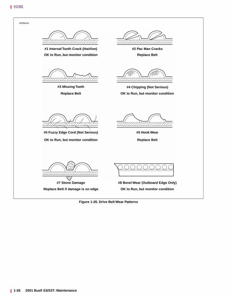
HOME
Figure 1-26. Drive Belt Wear Patterns
b0086a6x
#1 Internal Tooth Crack (Hairline)
OK to Run, but monitor condition
#3 Missing Teeth
Replace Belt
#5 Fuzzy Edge Cord (Not Serious)
OK to Run, but monitor condition
#7 Stone Damage
Replace Belt if damage is on edge
#2 Pac Man Cracks
Replace Belt
#4 Chipping (Not Serious)
OK to Run, but monitor condition
#5 Hook Wear
Replace Belt
#8 Bevel Wear (Outboard Edge Only)
OK to Run, but monitor condition
1-26 2001 Buell S3/S3T: Maintenance
HOME
PRIMARY CHAIN 1.11
INSPECTION
Check primary chain tension:
● At the 500 mile (800 km) service interval.
● At every 5000 mile (8000 km) service interval thereafter.
See Figure 1-27. Measure primary chain tension through theinspection cover (3) opening. Adjust primary chains not meet-ing vertical freeplay specifications.
1. See Figure 1-27. Remove two screws (1) and O-rings(2).
2. Remove inspection cover (3) and O-ring (4) from primarycover (6).
3. See Figure 1-28. Check primary chain tension by mea-suring vertical freeplay (4).
a. Measure vertical freeplay through inspection coveropening (2).
b. Rotate engine to move primary chain to a differentposition on sprockets (1, 3).
c. Measure vertical freeplay several times, each timewith primary chain moved so that the measurementis taken with sprockets rotated to the tightest chainposition.
4. The tightest measurement taken in Step 3 must be withinthe specifications listed in Table 1-6. If necessary, adjustas described under ADJUSTMENT.
NOTEThe initial primary chain vertical freeplay specification used atthe assembly plant is 1/4-1/2 in. (6.4-12.7 mm) with a coldengine. The 1/4 in. (6.4 mm) minimum is only allowed at theabsolute tightest point in the drive, as measured with special-ized factory equipment. If a chain has less than 1/4 in. (6.4mm) vertical freeplay (with a cold engine), adjust freeplay tothe “field” specification of 3/8-1/2 in. (9.5-12.7 mm). Thelooser specification will avoid overtightening, which might oth-erwise occur during adjustment using “non-factory” equip-ment and methods.
5. See Figure 1-27. Install O-ring (4).
6. Fasten inspection cover (3) to primary cover (6) usingtwo screws (1) with O-rings (2). Tighten to 40-60 in-lbs(5-7 Nm).
ADJUSTMENT
NOTEIf vertical freeplay cannot be set within the limits specified,then primary chain and/or chain adjuster are worn beyondadjustment limits. Replace parts as necessary. See Section6.
1. See Figure 1-29. Loosen locknut (1).
2. Turn adjusting screw (2):
a. Clockwise (inward) to reduce freeplay.
b. Counterclockwise (outward) to increase freeplay.
3. Tighten locknut (1) to 20-25 ft-lbs (27-34 Nm
Figure 1-27.
b0333x1x
1. Screw (2)2. O-Ring (2)3. Inspection Cover4. O-Ring5. Adjusting Screw and Locknut6. Primary Cover
4
2
315
6
2001 Buell S3/S3T: Maintenance 1-27
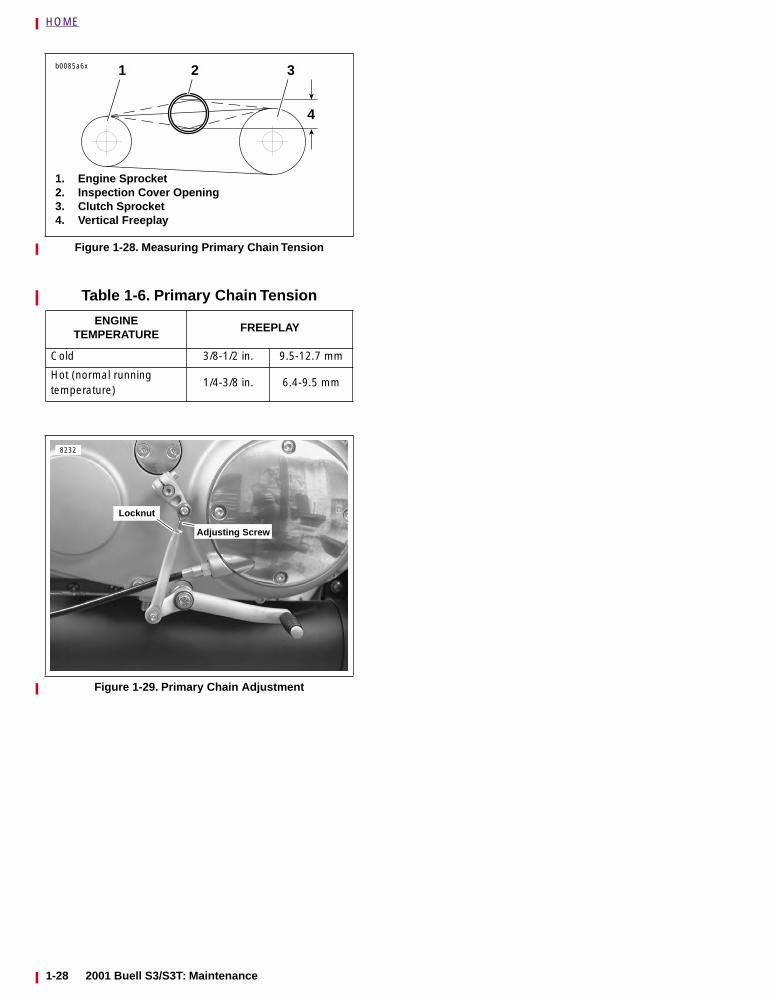
HOME
Figure 1-28. Measuring Primary Chain Tension
Table 1-6. Primary Chain Tension
ENGINETEMPERATURE
FREEPLAY
Cold 3/8-1/2 in. 9.5-12.7 mm
Hot (normal runningtemperature)
1/4-3/8 in. 6.4-9.5 mm
Figure 1-29. Primary Chain Adjustment
b0085a6x 1 3
4
2
1. Engine Sprocket2. Inspection Cover Opening3. Clutch Sprocket4. Vertical Freeplay
8232
Locknut
Adjusting Screw
1-28 2001 Buell S3/S3T: Maintenance
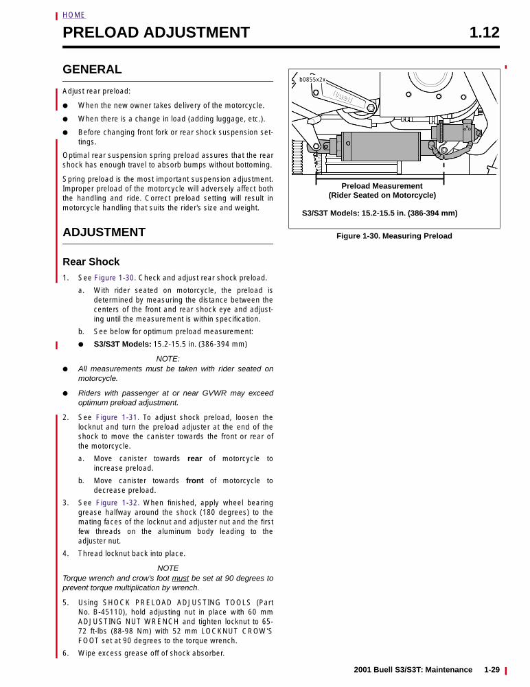
HOME
PRELOAD ADJUSTMENT 1.12
GENERAL
Adjust rear preload:
● When the new owner takes delivery of the motorcycle.
● When there is a change in load (adding luggage, etc.).
● Before changing front fork or rear shock suspension set-tings.
Optimal rear suspension spring preload assures that the rearshock has enough travel to absorb bumps without bottoming.
Spring preload is the most important suspension adjustment.Improper preload of the motorcycle will adversely affect boththe handling and ride. Correct preload setting will result inmotorcycle handling that suits the rider’s size and weight.
ADJUSTMENT
Rear Shock1. See Figure 1-30. Check and adjust rear shock preload.
a. With rider seated on motorcycle, the preload isdetermined by measuring the distance between thecenters of the front and rear shock eye and adjust-ing until the measurement is within specification.
b. See below for optimum preload measurement:
● S3/S3T Models: 15.2-15.5 in. (386-394 mm)
NOTE:● All measurements must be taken with rider seated on
motorcycle.
● Riders with passenger at or near GVWR may exceedoptimum preload adjustment.
2. See Figure 1-31. To adjust shock preload, loosen thelocknut and turn the preload adjuster at the end of theshock to move the canister towards the front or rear ofthe motorcycle.
a. Move canister towards rear of motorcycle toincrease preload.
b. Move canister towards front of motorcycle todecrease preload.
3. See Figure 1-32. When finished, apply wheel bearinggrease halfway around the shock (180 degrees) to themating faces of the locknut and adjuster nut and the firstfew threads on the aluminum body leading to theadjuster nut.
4. Thread locknut back into place.
NOTETorque wrench and crow’s foot must be set at 90 degrees toprevent torque multiplication by wrench.
5. Using SHOCK PRELOAD ADJUSTING TOOLS (PartNo. B-45110), hold adjusting nut in place with 60 mmADJUSTING NUT WRENCH and tighten locknut to 65-72 ft-lbs (88-98 Nm) with 52 mm LOCKNUT CROW’SFOOT set at 90 degrees to the torque wrench.
6. Wipe excess grease off of shock absorber.
Figure 1-30. Measuring Preload
S3/S3T Models: 15.2-15.5 in. (386-394 mm)
b0855x2x
Preload Measurement (Rider Seated on Motorcycle)
2001 Buell S3/S3T: Maintenance 1-29
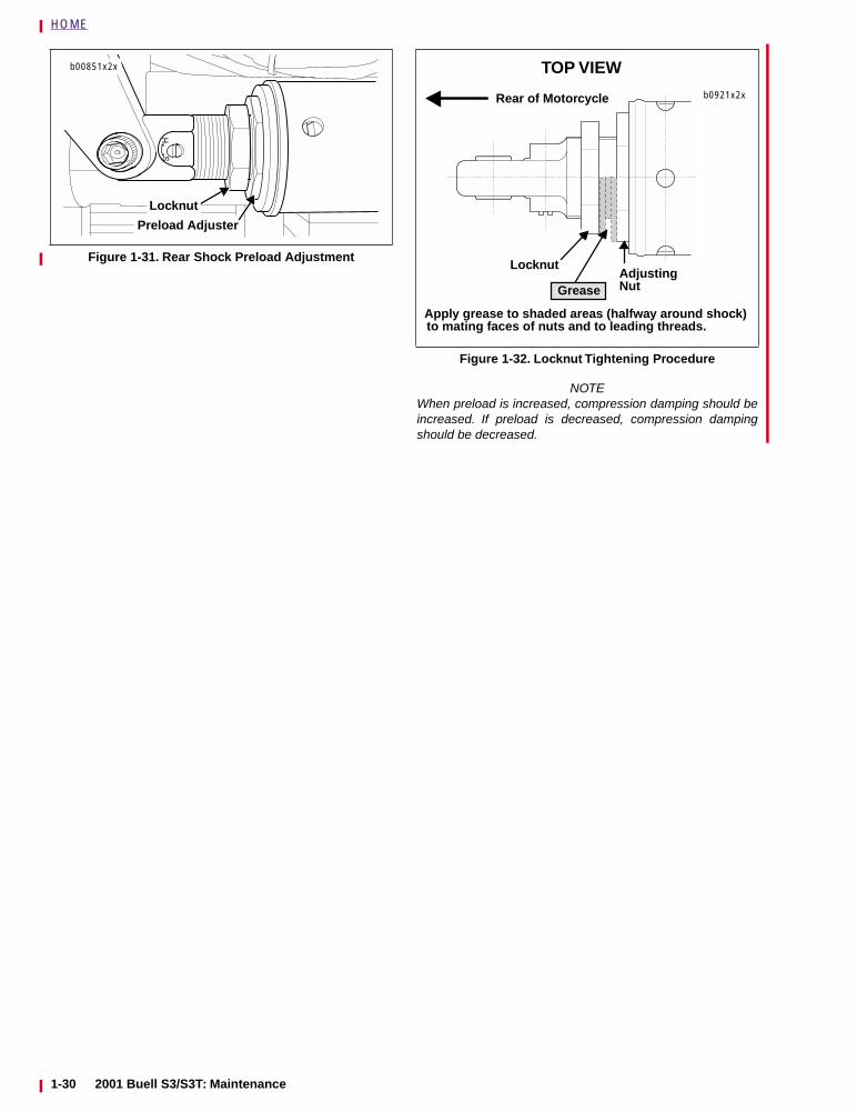
HOME
NOTEWhen preload is increased, compression damping should beincreased. If preload is decreased, compression dampingshould be decreased.
Figure 1-31. Rear Shock Preload Adjustment
Preload Adjuster
b00851x2x
Locknut
Figure 1-32. Locknut Tightening Procedure
b0921x2x
LocknutAdjustingNut
Apply grease to shaded areas (halfway around shock) to mating faces of nuts and to leading threads.
Grease
Rear of Motorcycle
TOP VIEW
1-30 2001 Buell S3/S3T: Maintenance
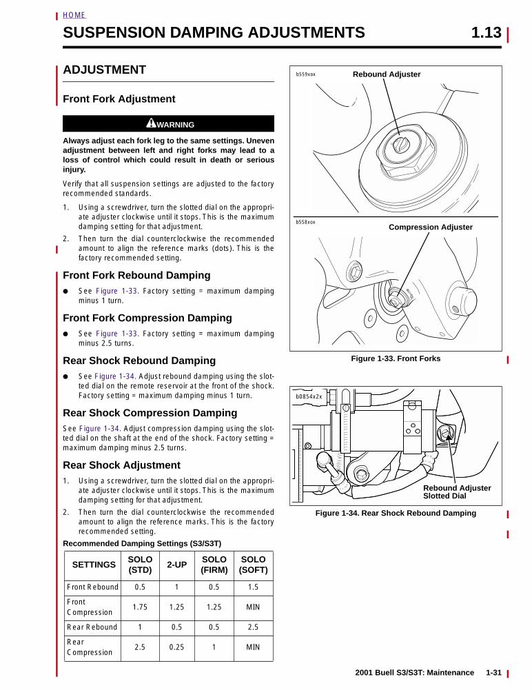
HOME
SUSPENSION DAMPING ADJUSTMENTS 1.13
ADJUSTMENT
Front Fork Adjustment
1WARNING1WARNING
Always adjust each fork leg to the same settings. Unevenadjustment between left and right forks may lead to aloss of control which could result in death or seriousinjury.
Verify that all suspension settings are adjusted to the factoryrecommended standards.
1. Using a screwdriver, turn the slotted dial on the appropri-ate adjuster clockwise until it stops. This is the maximumdamping setting for that adjustment.
2. Then turn the dial counterclockwise the recommendedamount to align the reference marks (dots). This is thefactory recommended setting.
Front Fork Rebound Damping● See Figure 1-33. Factory setting = maximum damping
minus 1 turn.
Front Fork Compression Damping● See Figure 1-33. Factory setting = maximum damping
minus 2.5 turns.
Rear Shock Rebound Damping● See Figure 1-34. Adjust rebound damping using the slot-
ted dial on the remote reservoir at the front of the shock.Factory setting = maximum damping minus 1 turn.
Rear Shock Compression DampingSee Figure 1-34. Adjust compression damping using the slot-ted dial on the shaft at the end of the shock. Factory setting =maximum damping minus 2.5 turns.
Rear Shock Adjustment1. Using a screwdriver, turn the slotted dial on the appropri-
ate adjuster clockwise until it stops. This is the maximumdamping setting for that adjustment.
2. Then turn the dial counterclockwise the recommendedamount to align the reference marks. This is the factoryrecommended setting.
Recommended Damping Settings (S3/S3T)
SETTINGSSOLO(STD)
2-UPSOLO(FIRM)
SOLO(SOFT)
Front Rebound 0.5 1 0.5 1.5
Front Compression
1.75 1.25 1.25 MIN
Rear Rebound 1 0.5 0.5 2.5
Rear Compression
2.5 0.25 1 MIN
Figure 1-33. Front Forks
Figure 1-34. Rear Shock Rebound Damping
Rebound Adjuster
Compression Adjuster
b559xox
b558xox
b0854x2x
Rebound AdjusterSlotted Dial
2001 Buell S3/S3T: Maintenance 1-31
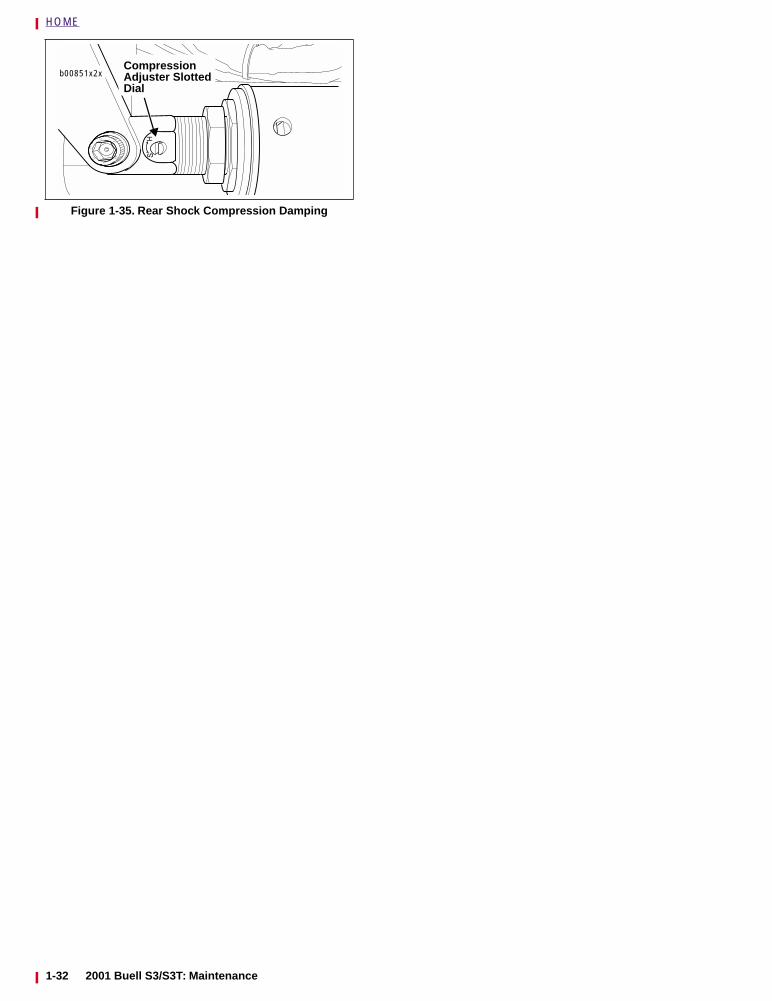
HOME
Figure 1-35. Rear Shock Compression Damping
Dial
CompressionAdjuster Slottedb00851x2x
1-32 2001 Buell S3/S3T: Maintenance
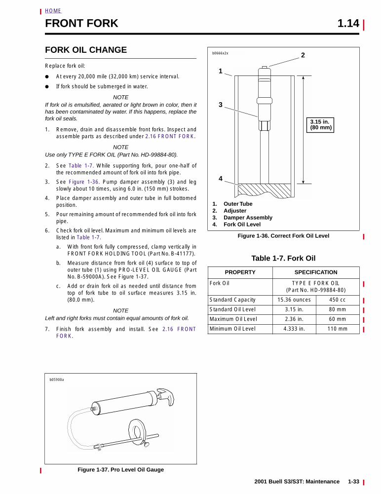
HOME
FRONT FORK 1.14
FORK OIL CHANGE
Replace fork oil:
● At every 20,000 mile (32,000 km) service interval.
● If fork should be submerged in water.
NOTEIf fork oil is emulsified, aerated or light brown in color, then ithas been contaminated by water. If this happens, replace thefork oil seals.
1. Remove, drain and disassemble front forks. Inspect andassemble parts as described under 2.16 FRONT FORK.
NOTEUse only TYPE E FORK OIL (Part No. HD-99884-80).
2. See Table 1-7. While supporting fork, pour one-half ofthe recommended amount of fork oil into fork pipe.
3. See Figure 1-36. Pump damper assembly (3) and legslowly about 10 times, using 6.0 in. (150 mm) strokes.
4. Place damper assembly and outer tube in full bottomedposition.
5. Pour remaining amount of recommended fork oil into forkpipe.
6. Check fork oil level. Maximum and minimum oil levels arelisted in Table 1-7.
a. With front fork fully compressed, clamp vertically inFRONT FORK HOLDING TOOL (Part No. B-41177).
b. Measure distance from fork oil (4) surface to top ofouter tube (1) using PRO-LEVEL OIL GAUGE (PartNo. B-59000A). See Figure 1-37.
c. Add or drain fork oil as needed until distance fromtop of fork tube to oil surface measures 3.15 in.(80.0 mm).
NOTELeft and right forks must contain equal amounts of fork oil.
7. Finish fork assembly and install. See 2.16 FRONTFORK.
Figure 1-37. Pro Level Oil Gauge
b05900a
Figure 1-36. Correct Fork Oil Level
Table 1-7. Fork Oil
PROPERTY SPECIFICATION
Fork Oil TYPE E FORK OIL(Part No. HD-99884-80)
Standard Capacity 15.36 ounces 450 cc
Standard Oil Level 3.15 in. 80 mm
Maximum Oil Level 2.36 in. 60 mm
Minimum Oil Level 4.333 in. 110 mm
b0666x2x
4
3
2
1. Outer Tube2. Adjuster3. Damper Assembly4. Fork Oil Level
1
3.15 in.(80 mm)
2001 Buell S3/S3T: Maintenance 1-33
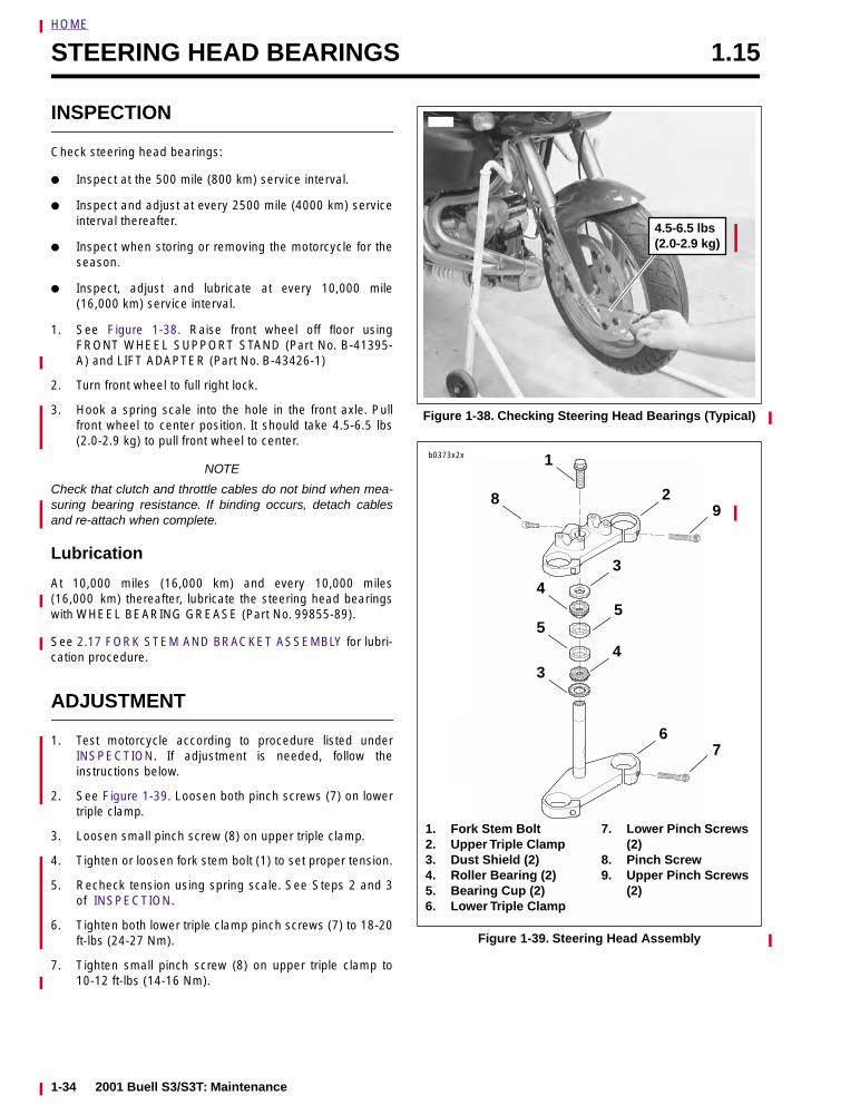
HOME
STEERING HEAD BEARINGS 1.15
INSPECTION
Check steering head bearings:
● Inspect at the 500 mile (800 km) service interval.
● Inspect and adjust at every 2500 mile (4000 km) serviceinterval thereafter.
● Inspect when storing or removing the motorcycle for theseason.
● Inspect, adjust and lubricate at every 10,000 mile(16,000 km) service interval.
1. See Figure 1-38. Raise front wheel off floor usingFRONT WHEEL SUPPORT STAND (Part No. B-41395-A) and LIFT ADAPTER (Part No. B-43426-1)
2. Turn front wheel to full right lock.
3. Hook a spring scale into the hole in the front axle. Pullfront wheel to center position. It should take 4.5-6.5 lbs(2.0-2.9 kg) to pull front wheel to center.
NOTE
Check that clutch and throttle cables do not bind when mea-suring bearing resistance. If binding occurs, detach cablesand re-attach when complete.
Lubrication
At 10,000 miles (16,000 km) and every 10,000 miles(16,000 km) thereafter, lubricate the steering head bearingswith WHEEL BEARING GREASE (Part No. 99855-89).
See 2.17 FORK STEM AND BRACKET ASSEMBLY for lubri-cation procedure.
ADJUSTMENT
1. Test motorcycle according to procedure listed underINSPECTION. If adjustment is needed, follow theinstructions below.
2. See Figure 1-39. Loosen both pinch screws (7) on lowertriple clamp.
3. Loosen small pinch screw (8) on upper triple clamp.
4. Tighten or loosen fork stem bolt (1) to set proper tension.
5. Recheck tension using spring scale. See Steps 2 and 3of INSPECTION.
6. Tighten both lower triple clamp pinch screws (7) to 18-20ft-lbs (24-27 Nm).
7. Tighten small pinch screw (8) on upper triple clamp to10-12 ft-lbs (14-16 Nm).
Figure 1-38. Checking Steering Head Bearings (Typical)
Figure 1-39. Steering Head Assembly
4.5-6.5 lbs (2.0-2.9 kg)
b0373x2x
28
1
3
5
4
4
5
3
67
9
1. Fork Stem Bolt2. Upper Triple Clamp3. Dust Shield (2)4. Roller Bearing (2)5. Bearing Cup (2)6. Lower Triple Clamp
7. Lower Pinch Screws (2)
8. Pinch Screw9. Upper Pinch Screws
(2)
1-34 2001 Buell S3/S3T: Maintenance
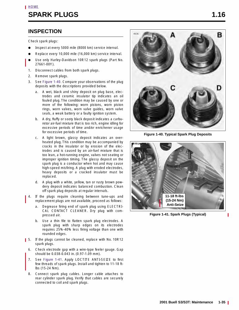
HOME
SPARK PLUGS 1.16
INSPECTION
Check spark plugs:
● Inspect at every 5000 mile (8000 km) service interval.
● Replace every 10,000 mile (16,000 km) service interval.
● Use only Harley-Davidson 10R12 spark plugs (Part No.27661-00Y).
1. Disconnect cables from both spark plugs.
2. Remove spark plugs.
3. See Figure 1-40. Compare your observations of the plugdeposits with the descriptions provided below.
a. A wet, black and shiny deposit on plug base, elec-trodes and ceramic insulator tip indicates an oilfouled plug. The condition may be caused by one ormore of the following: worn pistons, worn pistonrings, worn valves, worn valve guides, worn valveseals, a weak battery or a faulty ignition system.
b. A dry, fluffy or sooty black deposit indicates a carbu-retor air-fuel mixture that is too rich, engine idling forexcessive periods of time and/or enrichener usagefor excessive periods of time.
c. A light brown, glassy deposit indicates an over-heated plug. This condition may be accompanied bycracks in the insulator or by erosion of the elec-trodes and is caused by an air-fuel mixture that istoo lean, a hot-running engine, valves not seating orimproper ignition timing. The glassy deposit on thespark plug is a conductor when hot and may causehigh-speed misfiring. A plug with eroded electrodes,heavy deposits or a cracked insulator must bereplaced.
d. A plug with a white, yellow, tan or rusty brown pow-dery deposit indicates balanced combustion. Cleanoff spark plug deposits at regular intervals.
4. If the plugs require cleaning between tune-ups andreplacement plugs are not available, proceed as follows:
a. Degrease firing end of spark plug using ELECTRI-CAL CONTACT CLEANER. Dry plug with com-pressed air.
b. Use a thin file to flatten spark plug electrodes. Aspark plug with sharp edges on its electrodesrequires 25%-40% less firing voltage than one withrounded edges.
5. If the plugs cannot be cleaned, replace with No. 10R12spark plugs.
6. Check electrode gap with a wire-type feeler gauge. Gapshould be 0.038-0.043 in. (0.97-1.09 mm).
7. See Figure 1-41. Apply LOCTITE ANTI-SEIZE to firstfew threads of spark plugs. Install and tighten to 11-18 ft-lbs (15-24 Nm).
8. Connect spark plug cables. Longer cable attaches torear cylinder spark plug. Verify that cables are securelyconnected to coil and spark plugs.
Figure 1-40. Typical Spark Plug Deposits
Figure 1-41. Spark Plugs (Typical)
4636
11-18 ft-lbs(15-24 Nm)Anti-Seize
2001 Buell S3/S3T: Maintenance 1-35
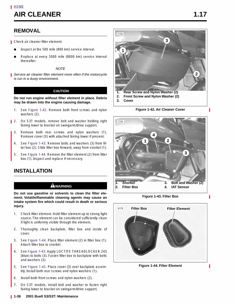
HOME
AIR CLEANER 1.17
REMOVAL
Check air cleaner filter element:
● Inspect at the 500 mile (800 km) service interval.
● Replace at every 5000 mile (8000 km) service intervalthereafter.
NOTE
Service air cleaner filter element more often if the motorcycleis run in a dusty environment.
CAUTION
Do not run engine without filter element in place. Debrismay be drawn into the engine causing damage.
1. See Figure 1-42. Remove both front screws and nylonwashers (2).
2. On S3T models, remove bolt and washer holding rightfairing lower to bracket on swingarm/drive support.
3. Remove both rear screws and nylon washers (1).Remove cover (3) with attached fairing lower if present.
4. See Figure 1-43. Remove bolts and washers (3) from fil-ter box (2). Slide filter box forward, away from snorkel (1).
5. See Figure 1-44. Remove the filter element (2) from filterbox (1). Inspect and replace if necessary.
INSTALLATION
1WARNING1WARNING
Do not use gasoline or solvents to clean the filter ele-ment. Volatile/flammable cleaning agents may cause anintake system fire which could result in death or seriousinjury.
1. Check filter element. Hold filter element up to strong lightsource. The element can be considered sufficiently cleanif light is uniformly visible through the element.
2. Thoroughly clean backplate, filter box and inside ofcover.
3. See Figure 1-44. Place filter element (2) in filter box (1).Attach filter box to snorkel.
4. See Figure 1-43. Apply LOCTITE THREADLOCKER 243(blue) to bolts (3). Fasten filter box to backplate with boltsand washers (3).
5. See Figure 1-42. Place cover (3) over backplate assem-bly. Install both rear screws and nylon washers (1).
6. Install both front screws and nylon washers (2).
7. On S3T models, install bolt and washer to fasten rightfairing lower to bracket on swingarm/drive support.
Figure 1-42. Air Cleaner Cover
Figure 1-43. Filter Box
Figure 1-44. Filter Element
1. Rear Screw and Nylon Washer (2)2. Front Screw and Nylon Washer (2)3. Cover
7158
1
2
3
1. Snorkel 2. Filter Box
3. Bolt and Washer (2)4. IAT Sensor
7156
42
3
1
6178 Filter Box Filter Element
1-36 2001 Buell S3/S3T: Maintenance
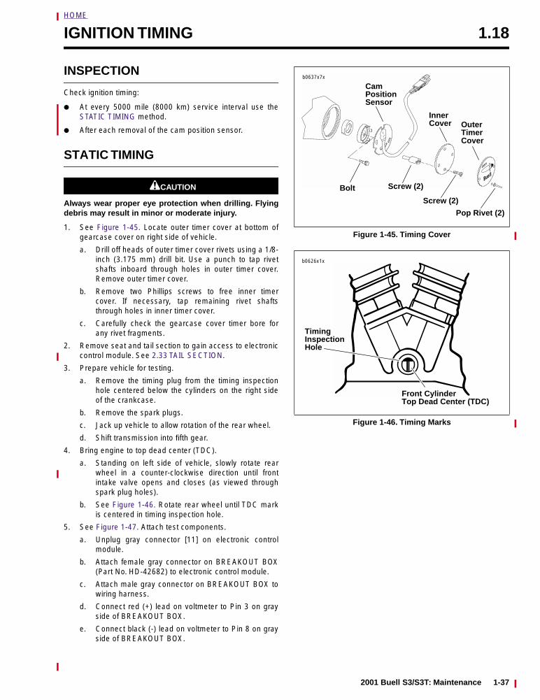
HOME
IGNITION TIMING 1.18
INSPECTION
Check ignition timing:
● At every 5000 mile (8000 km) service interval use theSTATIC TIMING method.
● After each removal of the cam position sensor.
STATIC TIMING
1CAUTION
Always wear proper eye protection when drilling. Flyingdebris may result in minor or moderate injury.
1. See Figure 1-45. Locate outer timer cover at bottom ofgearcase cover on right side of vehicle.
a. Drill off heads of outer timer cover rivets using a 1/8-inch (3.175 mm) drill bit. Use a punch to tap rivetshafts inboard through holes in outer timer cover.Remove outer timer cover.
b. Remove two Phillips screws to free inner timercover. If necessary, tap remaining rivet shaftsthrough holes in inner timer cover.
c. Carefully check the gearcase cover timer bore forany rivet fragments.
2. Remove seat and tail section to gain access to electroniccontrol module. See 2.33 TAIL SECTION.
3. Prepare vehicle for testing.
a. Remove the timing plug from the timing inspectionhole centered below the cylinders on the right sideof the crankcase.
b. Remove the spark plugs.
c. Jack up vehicle to allow rotation of the rear wheel.
d. Shift transmission into fifth gear.
4. Bring engine to top dead center (TDC).
a. Standing on left side of vehicle, slowly rotate rearwheel in a counter-clockwise direction until frontintake valve opens and closes (as viewed throughspark plug holes).
b. See Figure 1-46. Rotate rear wheel until TDC markis centered in timing inspection hole.
5. See Figure 1-47. Attach test components.
a. Unplug gray connector [11] on electronic controlmodule.
b. Attach female gray connector on BREAKOUT BOX(Part No. HD-42682) to electronic control module.
c. Attach male gray connector on BREAKOUT BOX towiring harness.
d. Connect red (+) lead on voltmeter to Pin 3 on grayside of BREAKOUT BOX.
e. Connect black (-) lead on voltmeter to Pin 8 on grayside of BREAKOUT BOX.
Figure 1-45. Timing Cover
Figure 1-46. Timing Marks
DDFI
b0637x7x
Bolt Screw (2)
Inner
Screw (2)
Outer
Cover
Cover
Pop Rivet (2)
Timer
CamPositionSensor
b0626x1x
Timing
Front Cylinder Top Dead Center (TDC)
InspectionHole
2001 Buell S3/S3T: Maintenance 1-37
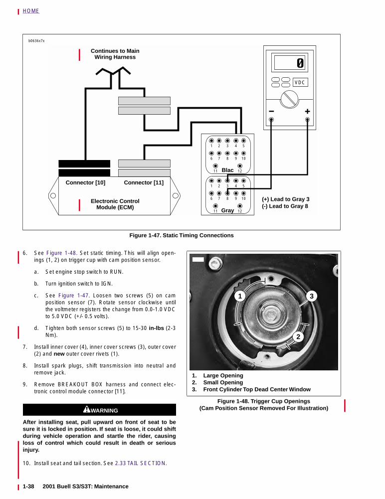
HOME
6. See Figure 1-48. Set static timing. This will align open-ings (1, 2) on trigger cup with cam position sensor.
a. Set engine stop switch to RUN.
b. Turn ignition switch to IGN.
c. See Figure 1-47. Loosen two screws (5) on camposition sensor (7). Rotate sensor clockwise untilthe voltmeter registers the change from 0.0-1.0 VDCto 5.0 VDC (+/- 0.5 volts).
d. Tighten both sensor screws (5) to 15-30 in-lbs (2-3Nm).
7. Install inner cover (4), inner cover screws (3), outer cover(2) and new outer cover rivets (1).
8. Install spark plugs, shift transmission into neutral andremove jack.
9. Remove BREAKOUT BOX harness and connect elec-tronic control module connector [11].
1WARNING1WARNING
After installing seat, pull upward on front of seat to besure it is locked in position. If seat is loose, it could shiftduring vehicle operation and startle the rider, causingloss of control which could result in death or seriousinjury.
10. Install seat and tail section. See 2.33 TAIL SECTION.
Figure 1-47. Static Timing Connections
1
6
2
7
3
8
4
9
5
VDC
10
11 12
1
6
2
7
3
8
4
9
5
10
11 12
Blac
Gray
Continues to Main Wiring Harness
Electronic Control Module (ECM)
(+) Lead to Gray 3(-) Lead to Gray 8
b0636x7x
Connector [10] Connector [11]
Figure 1-48. Trigger Cup Openings (Cam Position Sensor Removed For Illustration)
2
1
1. Large Opening2. Small Opening3. Front Cylinder Top Dead Center Window
3
1-38 2001 Buell S3/S3T: Maintenance
HOME
HANDLEBARS 1.19
INSPECTION
Check handlebar adjustment:
● Before every ride.
1WARNING1WARNING
Handlebars must not touch front forks or gas tank.Improperly adjusted handlebars may cause loss of con-trol which could result in death or serious injury.
1. See Figure 1-49. Check steering motion range to bothfork stops. Handlebars should not make contact with thefront forks, fuel tank or fairing.
2. Handlebars should be equally spaced between outsideedge of handlebar clamp and inside edge of mirrormounts.
If necessary, adjust handlebars as described below.
ADJUSTMENT
CAUTION
Never adjust handlebars using excessive force or dam-age to handlebars might result.
1. See Figure 1-50. Loosen clamp screws (1, 2).
2. Move handlebar to desired position.
3. Tighten clamp screws to 10-12 ft-lbs (14-16 Nm).
NOTE
First tighten the front clamp screws (1) to 10-12 ft-lbs (14-16Nm). Once the front clamp screws are tight, tighten the rearclamp screws to 10-12 ft-lbs (14-16 Nm).
1WARNING1WARNING
Handlebars must not touch front forks or gas tank.Improperly adjusted handlebars may cause loss of con-trol which could result in death or serious injury.
4. Check steering motion range to both fork stops. Handle-bars should not make contact with the front forks, fueltank or fairing.
If handlebar needs further adjustment, repeat adjust-ment beginning with Step 1.
Figure 1-49. Testing Handlebars (Typical)
Figure 1-50. Adjusting Handlebars
6089
6088
6286
1. Front Clamp Screws (2)2. Rear Clamp Screws (2)
2
1
2001 Buell S3/S3T: Maintenance 1-39
HOME
THROTTLE CABLES 1.20
ADJUSTMENT
1WARNING1WARNING
Throttle cables must not pull tight when handlebars areturned fully to left or right fork stops. Make sure wiresand throttle cables are clear of fork stops at steeringhead so they will not be pinched when fork is turnedagainst stops. Steering must be smooth and free with nobinding or interference. Anything interfering with throttleoperation or steering may cause loss of vehicle controlwhich could result in death or serious injury.
Check throttle cable adjustment:
● Before every ride.
● At every scheduled service interval.
Check throttle cable adjustment with engine running. Turnhandlebars through full range of travel. If engine speedchanges during this maneuver, adjust throttle cables as fol-lows:
1. Remove air cleaner cover and backplate. See 4.41 AIRCLEANER.
2. See Figure 1-51. Slide rubber boot (5) off each cableadjuster (4).
3. Loosen cable adjuster lock (3) on each cable (1, 2).
4. Turn adjusters in direction which will shorten cable hous-ings to minimum length.
5. Point front wheel straight ahead. Twist throttle controlgrip to fully open position; hold in position.
6. See Figure 1-52. Turn adjuster on throttle control cableuntil throttle cam stop (5) touches stop plate. Tighten jamnut on throttle control cable adjuster; release throttlecontrol grip.
7. Turn handlebars fully to right. Turn adjuster on idle con-trol cable (3) until end of cable housing just touches thecable guide (2).
8. See Figure 1-51. Twist and release throttle control grip afew times. Throttle plate must return to idle position eachtime throttle grip is released. If this is not the case, turnadjuster (4) on idle control cable (2) (shortening cablehousing) until throttle control functions properly.
9. Tighten cable adjuster lock (3) on idle control cable (2).Recheck operation of throttle control.
10. Slide rubber boot (5) over each cable adjuster (4).Recheck engine slow idle speed; adjust if required.
11. Install air cleaner assembly. See 4.41 AIR CLEANER.
IDLE ADJUSTMENT
Check idle adjustment:
● Before every ride.
● At every scheduled service interval.
Regular idle speed is 850-1050 RPM. Set idle speed usingidle adjuster and tachometer.
Figure 1-51. Throttle and Idle Cable Control Cables
Figure 1-52. Throttle Body Manifold (Typical)
1. Throttle Control Cable2. Idle Control Cable3. Cable Adjuster Lock4. Cable Adjuster5. Rubber Boot
6853
51
3
2
4
16955
2
4
5
1. Guide for Throttle Control Cable2. Guide for Idle Control Cable3. Idle Control Cable4. Idle Adjustment Screw (Typical)5. Throttle Cam Stop
3
1-40 2001 Buell S3/S3T: Maintenance
HOME
HEADLAMP 1.21
INSPECTION
1WARNING1WARNING
DO NOT modify the ignition/headlamp switch wiring tocircumvent the automatic-on headlamp feature. Ridingwithout an operating headlamp could cause an accident.Failure to comply could result in death or serious injury.
Check headlamp for proper height and lateral alignment:
● When the new owner takes delivery of the motorcycle.
● When there is a change in load (adding luggage, etc.)
1. Verify correct front and rear tire pressure. See 1.7 TIRESAND WHEELS.
2. Place motorcycle on level floor (or pavement) in an areawith minimum light.
3. See Figure 1-53. Position motorcycle 25 ft (7.62 meters)away from a screen or wall. Measure the distance fromdirectly below the front axle to the base of the screen/wall.
4. Draw a horizontal line 32 in. (81.3 cm) above floor onscreen/wall.
5. Load vehicle with rider/passenger/cargo/accessories.Weight will compress vehicle suspension slightly.
6. Stand motorcycle upright with both tires resting on floorand with front wheel held in straight alignment (directlyforward).
7. Turn ignition switch to IGN. Set handlebar headlampswitch to HIGH beam position.
8. Check light beam for alignment.
a. The main beam, which is a broad, flat pattern oflight, should be centered equally above and belowthe horizontal line.
b. The main beam of light should also be directedstraight ahead. Properly adjusted headlamps projectan equal area of light to right and left of center.
c. Adjust headlamp alignment if necessary. SeeADJUSTMENT.
ADJUSTMENT
If headlamp requires adjustment, perform the following:
1. Change height alignment by tilting headlamp up or downto aim it in relation to the horizontal line in Figure 1-53.
a. See Figure 1-54. Turn headlamp adjuster clockwiseto raise beam.
b. Turn headlamp adjuster counterclockwise to lowerbeam.
2. See Figure 1-55. Change lateral alignment by adjustingthe right side headlamp mounting stud with a nut driver.
a. Turn stud clockwise to shift headlamp beam to theright.
b. Turn stud counterclockwise to shift headlamp beamto the left.
Figure 1-53. Checking Headlamp Alignment
Figure 1-54. Headlamp Height Adjustment (Typical)
Figure 1-55. Headlamp Lateral Adjustment
25 ft(7.62 meters)
b0008c7x 32 in.(81.3 cm)
b0273box
Adjuster (behinddash panel)
6239
2001 Buell S3/S3T: Maintenance 1-41
HOME
STORAGE 1.22
GENERAL
If the motorcycle will not be operated for several months,such as during the winter season, there are several thingswhich should be done to protect parts against corrosion, topreserve the battery and to prevent the buildup of gum andvarnish in the fuel system.
This work should be performed by your local Buell dealer fol-lowing Service Manual procedures.
1WARNING1WARNING
Gasoline is flammable. Do not store motorcycle havinggasoline in tank within the home or garage where openflames, pilot lights, sparks or electric motors are present.Inadequate safety precautions may result in a fire orexplosion which could result in death or serious injury.
1. Fill fuel tank and add a gasoline stabilizer. Use one of thecommercially available gasoline stabilizers following themanufacturer’s instructions. Run engine until gasolinehas had a chance to reach fuel injectors.
2. Fill the oil tank. See 1.3 BATTERY. Pinch off (or removeand plug) the line leading from the oil tank bottom to theoil pump feed fitting. This prevents oil from seeping pastthe check ball into the oil pump and filling the engine fly-wheel compartment.
3. Remove battery and charge as needed to maintain thecorrect voltage. See 1.3 BATTERY.
4. Remove the spark plugs, inject a few squirts of engine oilinto each cylinder and crank the engine 5-6 revolutions.Reinstall spark plugs. See 1.16 SPARK PLUGS.
5. Adjust rear drive belt deflection. See 1.9 DRIVE BELTDEFLECTION.
6. Adjust primary chain. See 1.11 PRIMARY CHAIN.
7. Check tire inflation. See 1.7 TIRES AND WHEELS. If themotorcycle will be stored for an extended period of time,securely support the motorcycle under the frame so thatall weight is off the tires.
1WARNING1WARNING
Do not apply any oil to brake rotors or brake pads. Oil onbrake pads degrades braking efficiency and may causean accident which could result in death or serious injury.
8. Wash painted and chrome-plated surfaces. Apply a lightfilm of oil to exposed unpainted surfaces.
9. If motorcycle is to be covered, use a material that willbreathe, such as light canvas. Plastic materials that donot breathe promote the formation of condensation.
REMOVAL FROM STORAGE
1WARNING1WARNING
After extended periods of storage and prior to startingvehicle, place transmission in gear, disengage clutchand push vehicle back and forth a few times to ensureproper clutch disengagement. Improper clutch disen-gagement while vehicle is in motion may cause an acci-dent which could result in death or serious injury.
1. Charge and install battery. See 1.3 BATTERY.
2. Remove and inspect spark plugs. Replace if necessary.See 1.16 SPARK PLUGS.
3. Inspect air filter element. Replace if necessary. See 1.17AIR CLEANER.
4. If fuel tank was drained, fill fuel tank with fresh gasoline.
5. If oil feed line was pinched off or plugged, unplug it andreconnect.
6. Start the engine and run until it reaches normal operat-ing temperature. Check fluids and refill to proper levels ifrequired.
a. Check engine oil level. See 1.3 BATTERY.
b. Check transmission fluid level. See 1.8 CLUTCH.
7. Perform all of the checks in the PRE-RIDING CHECKLIST in the Owner’s Manual.
1-42 2001 Buell S3/S3T: Maintenance
HOME
TROUBLESHOOTING 1.23
GENERAL
The following check list can be helpful in locating most oper-ating troubles. Refer to the appropriate sections in this Ser-vice Manual for detailed procedures.
ENGINE
Starter Motor Does Not Operate or Does Not Turn Engine Over1. Engine stop switch in OFF position.
2. Ignition key switch not ON.
3. Discharged battery or loose or corroded connections.(Solenoid chatters.)
4. Starter control relay or solenoid not functioning.
5. Electric starter shaft pinion gear not engaging or over-running clutch slipping.
Engine Turns Over But Does Not Start1. Fuel tank empty.
2. Discharged battery, loose or broken battery terminal con-nections.
3. Fouled spark plugs.
4. Loose or shorting spark plug cables or connections.
5. Tripped bank angle sensor. Turn key to OFF and thenback to IGN again to start bike.
6. Clogged fuel filter (on pump or in-line).
7. Clogged fuel injectors. See dealer.
8. Inadequate fuel pressure in fuel lines (possible leak).See dealer.
9. Inoperative fuel pump. See dealer.
10. No output from the ECM. See dealer.
11. TPS/fast idle screw not set properly. See dealer.
12. Ignition coil not functioning.
13. No output from CMP sensor. See dealer.
14. Sticking or damaged valve or valves.
15. Engine oil too heavy (winter operation).
Starts Hard1. Spark plugs in bad condition, have improper gap or are
partially fouled.
2. Spark plug cables in bad condition and shorting.
3. Battery nearly discharged.
4. Loose wire connection at one of the battery terminals, atcoil or at plug between ignition sensor and module.
5. TPS and/or fast idle screw not set properly. See dealer.
6. O2, IAT or ET sensors damaged or malfunctioning. Seedealer.
7. Ignition coil not functioning.
8. Engine oil too heavy (winter operation).
9. Water or dirt in fuel system/clogged fuel filter/injector.
10. Air leak at intake manifold.
11. Valves sticking.
Starts But Runs Irregularly or Misses1. Fuel level too low. Add gasoline.
2. Battery nearly discharged.
3. Spark plugs in bad condition or partially fouled.
4. Spark plug cables in bad condition and shorting.
5. Spark plug gap too close or too wide.
6. Ignition coil not functioning.
7. Obstructed fuel tank vent valve or pinched vent tube.See dealer.
8. O2, IAT or ET sensors damaged or malfunctioning. Seedealer.
9. Damaged wire or loose connection at battery terminalsor coil.
10. Intermittent short circuit due to damaged wire insulation.
11. Water or dirt in fuel system/partially clogged fuel filter/injector.
12. Vapor vent valve plugged or carburetor float bowl ventclosed off.
13. TPS and/or fast idle screw not set properly. See dealer.
14. Inoperative fuel injector. See dealer.
15. Air leak at intake manifold or air filter.
16. Damaged intake or exhaust valve.
17. Weak or broken valve springs.
18. Incorrect valve timing.
Spark Plug Fouls Repeatedly1. Incorrect spark plug.
2. Piston rings badly worn or broken.
3. Fuel mixture too rich for conditions (see CARBURETORTROUBLESHOOTING).
4. Valve stem seals worn or damaged.
5. Valve guides badly worn.
Pre-Ignition or Detonation(Knocks or Pings)1. Excessive carbon deposit on piston head or combustion
chamber.
2. Incorrect heat range spark plug.
3. Spark plugs not firing.
4. Ignition timing advanced.
5. Fuel octane rating too low.
6. Intake manifold vacuum leak.
Overheating1. Insufficient oil supply or oil not circulating.
2. Leaking valves.
3. Heavy carbon deposit.
4. Ignition timing retarded.
2001 Buell S3/S3T: Maintenance 1-43
HOME
Valve Train Noise1. Hydraulic lifter not functioning properly.
2. Bent push rod.
3. Cam, cam gears or cam bushings worn.
4. Rocker arm binding on shaft.
5. Valve sticking in guide.
Excessive Vibration1. Engine tie-bars loose, broken or improperly spaced.
2. Lower mounting bolts loose.
3. Broken frame.
4. Primary chain badly worn or links tight as a result ofinsufficient lubrication.
5. Wheels not aligned and/or tires worn.
6. Internal engine problem.
ENGINE LUBRICATIONSYSTEM
Oil Does Not Return To Oil Tank1. Oil tank empty.
2. Return pump gears damaged.
3. Oil feed pump not functioning.
4. Restricted oil lines or fittings.
Engine Uses Too Much Oil or Smokes Excessively1. Piston rings badly worn or broken.
2. Valve stem seals worn or damaged.
3. Valve guides worn.
Engine Leaks Oil From Cases, Push Rods, Hoses, Etc.1. Loose parts.
2. Imperfect seal at gaskets, push rod cover, washers, etc.To aid locating leaks, use -35457).
3. Restricted oil return line to tank.
4. Restricted breather passage(s) to air cleaner.
ELECTRICAL SYSTEM
Alternator Does Not Charge1. Regulator-rectifier module not functioning.
2. Rectifier not grounded.
3. Engine ground wire loose or broken.
4. Loose or broken wires in charging circuit.
5. Stator not functioning.
6. Rotor not functioning.
Alternator Charge Rate Is Below Normal1. Regulator-rectifier module not functioning.
2. Stator not functioning.
3. Rotor not functioning.
4. Weak battery.
5. Loose connections.
FUEL
Poor Fuel Economy1. Excessive “pumping” of throttle control grip.
2. O2 sensor damaged or malfunctioning (bike runningrich). See dealer.
3. Inlet valve sticking.
4. Inlet valve and/or valve seat worn or damaged.
5. Dirt or other foreign matter between valve and its seat.
TRANSMISSION
Shifts Hard1. Clutch dragging slightly.
2. Shifter forks (inside transmission) damaged.
3. Corners worn off shifter clutch dogs (inside transmis-sion).
Jumps Out of Gear1. Shifter pawl improperly adjusted.
2. Shifter engaging parts (inside transmission) badly wornand rounded.
3. Shifter forks bent.
4. Damaged gears.
CLUTCH
Slips1. Clutch controls improperly adjusted.
2. Worn friction plates.
Drags or Does Not Release1. Clutch controls improperly adjusted.
2. Clutch plates excessively warped.
Chatters1. Friction or steel plates worn, warped or dragging.
CHASSIS
Irregular/Inadequate Brake Action1. Master cylinder low on fluid.
2. Brake line contains air bubbles.
3. Master or wheel cylinder piston worn.
4. Brake pads covered with grease or oil.
5. Brake pads badly worn to minimum lining thickness.
6. Brake rotor badly worn or warped.
1-44 2001 Buell S3/S3T: Maintenance
HOME
7. Brake pads dragging or excessive braking (brake fadesdue to heat buildup).
8. Insufficient brake pedal or hand lever freeplay (brakedrags).
Handling Irregularities1. Tires improperly inflated. See 1.7 TIRES AND WHEELS.
Do not overinflate.
2. Loose wheel axle nuts (metric). Tighten front nut to 48-53 ft-lbs (65-72 Nm). Tighten rear nut to 66-73 ft-lbs (90-99 Nm).
3. Excessive wheel hub bearing play.
4. Rear wheel out of alignment with frame and front wheel.
5. Rims and tires out-of-true sideways (tire runout shouldnot be more than 0.080 in. (2.03 mm)).
6. Rims and tires out-of-round or eccentric with hub (tirerunout should not be more than 0.090 in. (2.29 mm)).
7. Irregular or peaked front tire tread wear.
8. Tire and wheel unbalanced.
9. Steering head bearings improperly adjusted. See 1.15STEERING HEAD BEARINGS. Correct adjustment andreplace pitted or worn bearings and races. See 2.17FORK STEM AND BRACKET ASSEMBLY.
10. Shock absorber not functioning normally.
11. Heavy front end loading. Non-standard equipment on thefront end (such as heavy radio receivers, extra lightingequipment or luggage) tends to cause unstable handling.
2001 Buell S3/S3T: Maintenance 1-45

HOME
NOTES
1-46 2001 Buell S3/S3T: Maintenance

CHASSIS 2
SUBJECT PAGE NO.
2.1 Specifications . . . . . . . . . . . . . . . . . . . . . . . . . . . . . . . . . . . . . . . . . . . . . . . . . . 2-12.2 Tire Specifications . . . . . . . . . . . . . . . . . . . . . . . . . . . . . . . . . . . . . . . . . . . . . . 2-42.3 Vehicle Identification Number . . . . . . . . . . . . . . . . . . . . . . . . . . . . . . . . . . . . . 2-52.4 Wheels . . . . . . . . . . . . . . . . . . . . . . . . . . . . . . . . . . . . . . . . . . . . . . . . . . . . . . . 2-62.5 Front Wheel . . . . . . . . . . . . . . . . . . . . . . . . . . . . . . . . . . . . . . . . . . . . . . . . . . . 2-82.6 Rear Wheel . . . . . . . . . . . . . . . . . . . . . . . . . . . . . . . . . . . . . . . . . . . . . . . . . . . 2-102.7 Checking Cast Rim Runout . . . . . . . . . . . . . . . . . . . . . . . . . . . . . . . . . . . . . . . 2-122.8 Tires . . . . . . . . . . . . . . . . . . . . . . . . . . . . . . . . . . . . . . . . . . . . . . . . . . . . . . . . . 2-132.9 Brakes . . . . . . . . . . . . . . . . . . . . . . . . . . . . . . . . . . . . . . . . . . . . . . . . . . . . . . . 2-162.10 Front Brake Master Cylinder . . . . . . . . . . . . . . . . . . . . . . . . . . . . . . . . . . . . . 2-182.11 Front Brake Caliper . . . . . . . . . . . . . . . . . . . . . . . . . . . . . . . . . . . . . . . . . . . . 2-212.12 Front Brake Line . . . . . . . . . . . . . . . . . . . . . . . . . . . . . . . . . . . . . . . . . . . . . . 2-242.13 Rear Brake Master Cylinder . . . . . . . . . . . . . . . . . . . . . . . . . . . . . . . . . . . . . 2-252.14 Rear Brake Caliper . . . . . . . . . . . . . . . . . . . . . . . . . . . . . . . . . . . . . . . . . . . . 2-282.15 Rear Brake Line and Switch . . . . . . . . . . . . . . . . . . . . . . . . . . . . . . . . . . . . . 2-302.16 Front Fork . . . . . . . . . . . . . . . . . . . . . . . . . . . . . . . . . . . . . . . . . . . . . . . . . . . 2-322.17 Fork Stem and Bracket Assembly . . . . . . . . . . . . . . . . . . . . . . . . . . . . . . . . . 2-372.18 Steering Head Lock . . . . . . . . . . . . . . . . . . . . . . . . . . . . . . . . . . . . . . . . . . . . 2-382.19 Swingarm . . . . . . . . . . . . . . . . . . . . . . . . . . . . . . . . . . . . . . . . . . . . . . . . . . . . 2-392.20 Rear Isolators . . . . . . . . . . . . . . . . . . . . . . . . . . . . . . . . . . . . . . . . . . . . . . . . 2-432.21 Rear Shock Absorber . . . . . . . . . . . . . . . . . . . . . . . . . . . . . . . . . . . . . . . . . . 2-472.22 Suspension Theory . . . . . . . . . . . . . . . . . . . . . . . . . . . . . . . . . . . . . . . . . . . . 2-492.23 Suspension Adjustments . . . . . . . . . . . . . . . . . . . . . . . . . . . . . . . . . . . . . . . . 2-502.24 Throttle Control . . . . . . . . . . . . . . . . . . . . . . . . . . . . . . . . . . . . . . . . . . . . . . . 2-532.25 Clutch Control . . . . . . . . . . . . . . . . . . . . . . . . . . . . . . . . . . . . . . . . . . . . . . . . 2-552.26 Handlebars . . . . . . . . . . . . . . . . . . . . . . . . . . . . . . . . . . . . . . . . . . . . . . . . . . 2-572.27 Exhaust System . . . . . . . . . . . . . . . . . . . . . . . . . . . . . . . . . . . . . . . . . . . . . . . 2-582.28 Footrests . . . . . . . . . . . . . . . . . . . . . . . . . . . . . . . . . . . . . . . . . . . . . . . . . . . . 2-622.29 Sprocket Cover . . . . . . . . . . . . . . . . . . . . . . . . . . . . . . . . . . . . . . . . . . . . . . . 2-632.30 Stone Guard . . . . . . . . . . . . . . . . . . . . . . . . . . . . . . . . . . . . . . . . . . . . . . . . . 2-642.31 Front Fender . . . . . . . . . . . . . . . . . . . . . . . . . . . . . . . . . . . . . . . . . . . . . . . . . 2-652.32 Rear Fender . . . . . . . . . . . . . . . . . . . . . . . . . . . . . . . . . . . . . . . . . . . . . . . . . . 2-662.33 Tail Section . . . . . . . . . . . . . . . . . . . . . . . . . . . . . . . . . . . . . . . . . . . . . . . . . . 2-672.34 Front Fairing . . . . . . . . . . . . . . . . . . . . . . . . . . . . . . . . . . . . . . . . . . . . . . . . . 2-692.35 Seat . . . . . . . . . . . . . . . . . . . . . . . . . . . . . . . . . . . . . . . . . . . . . . . . . . . . . . . . 2-712.36 Side Stand . . . . . . . . . . . . . . . . . . . . . . . . . . . . . . . . . . . . . . . . . . . . . . . . . . . 2-732.37 Saddlebags (S3T Models) . . . . . . . . . . . . . . . . . . . . . . . . . . . . . . . . . . . . . . . 2-742.38 Fairing Lowers (S3T Models) . . . . . . . . . . . . . . . . . . . . . . . . . . . . . . . . . . . . . 2-76
Table Of Contents

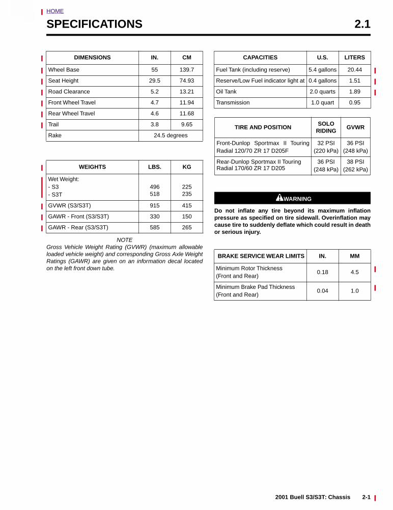
HOME
2
SPECIFICATIONS 2.1
NOTEGross Vehicle Weight Rating (GVWR) (maximum allowableloaded vehicle weight) and corresponding Gross Axle WeightRatings (GAWR) are given on an information decal locatedon the left front down tube.
11WARNING1WARNING
Do not inflate any tire beyond its maximum inflationpressure as specified on tire sidewall. Overinflation maycause tire to suddenly deflate which could result in deathor serious injury.
DIMENSIONS IN. CM
Wheel Base 55 139.7
Seat Height 29.5 74.93
Road Clearance 5.2 13.21
Front Wheel Travel 4.7 11.94
Rear Wheel Travel 4.6 11.68
Trail 3.8 9.65
Rake 24.5 degrees
WEIGHTS LBS. KG
Wet Weight: - S3- S3T
496518
225235
GVWR (S3/S3T) 915 415
GAWR - Front (S3/S3T) 330 150
GAWR - Rear (S3/S3T) 585 265
CAPACITIES U.S. LITERS
Fuel Tank (including reserve) 5.4 gallons 20.44
Reserve/Low Fuel indicator light at 0.4 gallons 1.51
Oil Tank 2.0 quarts 1.89
Transmission 1.0 quart 0.95
TIRE AND POSITIONSOLO
RIDING GVWR
Front-Dunlop Sportmax II TouringRadial 120/70 ZR 17 D205F
32 PSI (220 kPa)
36 PSI (248 kPa)
Rear-Dunlop Sportmax II Touring Radial 170/60 ZR 17 D205
36 PSI(248 kPa)
38 PSI (262 kPa)
BRAKE SERVICE WEAR LIMITS IN. MM
Minimum Rotor Thickness (Front and Rear)
0.18 4.5
Minimum Brake Pad Thickness (Front and Rear)
0.04 1.0
2001 Buell S3/S3T: Chassis 2-1
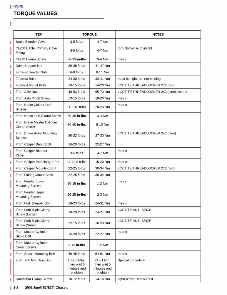
HOME
TORQUE VALUES
ITEM TORQUE NOTES
Brake Bleeder Valve 3-5 ft-lbs 4-7 Nm
Clutch Cable, Primary Cover Fitting
3-5 ft-lbs 4-7 Nmturn clockwise to install
Clutch Clamp Screw 30-33 in-lbs 3-4 Nm metric
Drive Support Nut 30-35 ft-lbs 41-47 Nm
Exhaust Header Nuts 6-8 ft-lbs 8-11 Nm
Footrest Bolts 24-30 ft-lbs 33-41 Nm must be tight, but not binding
Footrest Mount Bolts 10-15 ft-lbs 14-20 Nm LOCTITE THREADLOCKER 272 (red)
Front Axle Nut 48-53 ft-lbs 65-72 Nm LOCTITE THREADLOCKER 243 (blue), metric
Front Axle Pinch Screw 13-15 ft-lbs 18-20 Nm metric
Front Brake Caliper Half Screws
14.5-18 ft-lbs 20-24 Nmmetric
Front Brake Line Clamp Screw 30-35 in-lbs 3-4 Nm
Front Brake Master Cylinder Clamp Screw
80-90 in-lbs 9-10 Nm
Front Brake Rotor Mounting Screws
20-22 ft-lbs 27-30 NmLOCTITE THREADLOCKER 243 (blue)
Front Caliper Banjo Bolt 16-20 ft-lbs 22-27 Nm
Front Caliper Bleeder Valve
3-5 ft-lbs 4-7 Nmmetric
Front Caliper Pad Hanger Pin 11-14.5 ft-lbs 15-20 Nm metric
Front Caliper Mounting Bolt 22-25 ft-lbs 30-34 Nm LOCTITE THREADLOCKER 272 (red)
Front Fairing Mount Bolts 22-25 ft-lbs 30-34 Nm
Front Fender Lower Mounting Screws
10-15 in-lbs 1-2 Nmmetric
Front Fender Upper Mounting Screws
20-25 in-lbs 2-3 Nm
Front Fork Damper Bolt 18-23 ft-lbs 24-31 Nm metric
Front Fork Triple Clamp Screw (Large)
18-20 ft-lbs 24-27 NmLOCTITE ANTI-SEIZE
Front Fork Triple Clamp Screw (Small)
12-15 ft-lbs 16-20 NmLOCTITE ANTI-SEIZE
Front Master Cylinder Banjo Bolt
16-20 ft-lbs 22-27 Nmmetric
Front Master Cylinder Cover Screws
9-13 in-lbs 1-2 Nm
Front Shock Mounting Bolt 40-45 ft-lbs 54-61 Nm metric
Fuel Tank Mounting Bolt 18-23 ft-lbs, then wait 5
minutes and retighten.
24-31 Nm,then wait 5
minutes and retighten.
Special procedure.
Handlebar Clamp Screw 10-12 ft-lbs 14-16 Nm tighten front screws first
2-2 2001 Buell S3/S3T: Chassis
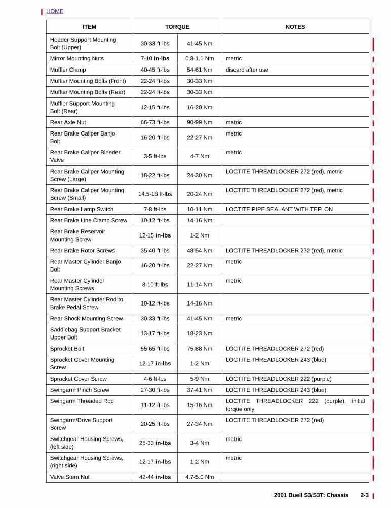
HOME
Header Support Mounting Bolt (Upper)
30-33 ft-lbs 41-45 Nm
Mirror Mounting Nuts 7-10 in-lbs 0.8-1.1 Nm metric
Muffler Clamp 40-45 ft-lbs 54-61 Nm discard after use
Muffler Mounting Bolts (Front) 22-24 ft-lbs 30-33 Nm
Muffler Mounting Bolts (Rear) 22-24 ft-lbs 30-33 Nm
Muffler Support Mounting Bolt (Rear)
12-15 ft-lbs 16-20 Nm
Rear Axle Nut 66-73 ft-lbs 90-99 Nm metric
Rear Brake Caliper BanjoBolt
16-20 ft-lbs 22-27 Nmmetric
Rear Brake Caliper Bleeder Valve
3-5 ft-lbs 4-7 Nmmetric
Rear Brake Caliper Mounting Screw (Large)
18-22 ft-lbs 24-30 NmLOCTITE THREADLOCKER 272 (red), metric
Rear Brake Caliper Mounting Screw (Small)
14.5-18 ft-lbs 20-24 NmLOCTITE THREADLOCKER 272 (red), metric
Rear Brake Lamp Switch 7-8 ft-lbs 10-11 Nm LOCTITE PIPE SEALANT WITH TEFLON
Rear Brake Line Clamp Screw 10-12 ft-lbs 14-16 Nm
Rear Brake Reservoir Mounting Screw
12-15 in-lbs 1-2 Nm
Rear Brake Rotor Screws 35-40 ft-lbs 48-54 Nm LOCTITE THREADLOCKER 272 (red), metric
Rear Master Cylinder Banjo Bolt
16-20 ft-lbs 22-27 Nmmetric
Rear Master Cylinder Mounting Screws
8-10 ft-lbs 11-14 Nmmetric
Rear Master Cylinder Rod to Brake Pedal Screw
10-12 ft-lbs 14-16 Nm
Rear Shock Mounting Screw 30-33 ft-lbs 41-45 Nm metric
Saddlebag Support Bracket Upper Bolt
13-17 ft-lbs 18-23 Nm
Sprocket Bolt 55-65 ft-lbs 75-88 Nm LOCTITE THREADLOCKER 272 (red)
Sprocket Cover Mounting Screw
12-17 in-lbs 1-2 NmLOCTITE THREADLOCKER 243 (blue)
Sprocket Cover Screw 4-6 ft-lbs 5-9 Nm LOCTITE THREADLOCKER 222 (purple)
Swingarm Pinch Screw 27-30 ft-lbs 37-41 Nm LOCTITE THREADLOCKER 243 (blue)
Swingarm Threaded Rod11-12 ft-lbs 15-16 Nm
LOCTITE THREADLOCKER 222 (purple), initialtorque only
Swingarm/Drive Support Screw
20-25 ft-lbs 27-34 NmLOCTITE THREADLOCKER 272 (red)
Switchgear Housing Screws, (left side)
25-33 in-lbs 3-4 Nmmetric
Switchgear Housing Screws, (right side)
12-17 in-lbs 1-2 Nmmetric
Valve Stem Nut 42-44 in-lbs 4.7-5.0 Nm
ITEM TORQUE NOTES
2001 Buell S3/S3T: Chassis 2-3
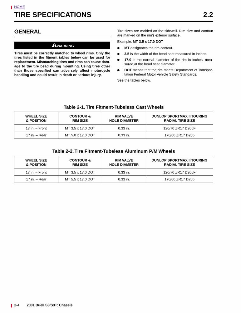
HOME
TIRE SPECIFICATIONS 2.2
GENERAL
11WARNING1WARNING
Tires must be correctly matched to wheel rims. Only thetires listed in the fitment tables below can be used forreplacement. Mismatching tires and rims can cause dam-age to the tire bead during mounting. Using tires otherthan those specified can adversely affect motorcyclehandling and could result in death or serious injury.
Tire sizes are molded on the sidewall. Rim size and contourare marked on the rim’s exterior surface.
Example: MT 3.5 x 17.0 DOT
● MT designates the rim contour.
● 3.5 is the width of the bead seat measured in inches.
● 17.0 is the normal diameter of the rim in inches, mea-sured at the bead seat diameter.
● DOT means that the rim meets Department of Transpor-tation Federal Motor Vehicle Safety Standards.
See the tables below.
Table 2-1. Tire Fitment-Tubeless Cast Wheels
WHEEL SIZE & POSITION
CONTOUR &RIM SIZE
RIM VALVE HOLE DIAMETER
DUNLOP SPORTMAX II TOURING RADIAL TIRE SIZE
17 in. – Front MT 3.5 x 17.0 DOT 0.33 in. 120/70 ZR17 D205F
17 in. – Rear MT 5.0 x 17.0 DOT 0.33 in. 170/60 ZR17 D205
Table 2-2. Tire Fitment-Tubeless Aluminum P/M Wheels
WHEEL SIZE & POSITION
CONTOUR &RIM SIZE
RIM VALVE HOLE DIAMETER
DUNLOP SPORTMAX II TOURING RADIAL TIRE SIZE
17 in. – Front MT 3.5 x 17.0 DOT 0.33 in. 120/70 ZR17 D205F
17 in. – Rear MT 5.5 x 17.0 DOT 0.33 in. 170/60 ZR17 D205
2-4 2001 Buell S3/S3T: Chassis

HOME
VEHICLE IDENTIFICATION NUMBER 2.3
GENERAL
The full 17 digit serial or Vehicle Identification Number (V.I.N.)is stamped on the steering head and on an information decalon the left front down tube.
See Figure 2-1. An abbreviated V.I.N. is stamped on the frontleft side of the crankcase.
NOTESee Figure 2-2. Always give the V.I.N. or abbreviated V.I.N.when ordering parts or making inquiries about your Buellmotorcycle.
Figure 2-1. Abbreviated V.I.N. Location
b0304x2x
Figure 2-2. 2001 Model Year Thunderbolt S3/S3T V.I.N.s
4 MZ RS 11 J * 1 3 000001*Varies - can be 0-9 or X
Sample S3 V.I.N. as it appears on the steering head - 4MZRS11J113000001Sample abbreviated S3 V.I.N. as it appears on the left side crankcase - RS111000001Sample S3T V.I.N. as it appears on the steering head - 4MZFS11J113100001Sample abbreviated S3T V.I.N. as it appears on the left side crankcase - FS111100001
11 = World56 = California
Manufacturer: Buell Motorcycle Company
Horsepower Code
Engine
Model Year:
SequentialNumber
000001-020000 = World020001-025000 = CA
Type Designation: FS = S3TRS= S3
1 = 2001 Model Year
2001 Buell S3/S3T: Chassis 2-5
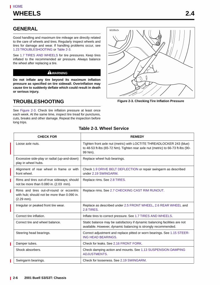
HOME
WHEELS 2.4
GENERAL
Good handling and maximum tire mileage are directly relatedto the care of wheels and tires. Regularly inspect wheels andtires for damage and wear. If handling problems occur, see1.23 TROUBLESHOOTING or Table 2-3.
See 1.7 TIRES AND WHEELS for tire pressures. Keep tiresinflated to the recommended air pressure. Always balancethe wheel after replacing a tire.
11WARNING1WARNING
Do not inflate any tire beyond its maximum inflationpressure as specified on tire sidewall. Overinflation maycause tire to suddenly deflate which could result in deathor serious injury.
TROUBLESHOOTING
See Figure 2-3. Check tire inflation pressure at least onceeach week. At the same time, inspect tire tread for punctures,cuts, breaks and other damage. Repeat the inspection beforelong trips.
Figure 2-3. Checking Tire Inflation Pressure
b0195x2x
Table 2-3. Wheel Service
CHECK FOR REMEDY
Loose axle nuts. Tighten front axle nut (metric) with LOCTITE THREADLOCKER 243 (blue) to 48-53 ft-lbs (65-72 Nm). Tighten rear axle nut (metric) to 66-73 ft-lbs (90-99 Nm).
Excessive side-play or radial (up-and-down)play in wheel hubs.
Replace wheel hub bearings.
Alignment of rear wheel in frame or withfront wheel.
Check 1.9 DRIVE BELT DEFLECTION or repair swingarm as described under 2.19 SWINGARM.
Rims and tires out-of-true sideways; shouldnot be more than 0.080 in. (2.03 mm).
Replace rims. See 2.8 TIRES.
Rims and tires out-of-round or eccentricwith hub; should not be more than 0.090 in.(2.29 mm).
Replace rims. See 2.7 CHECKING CAST RIM RUNOUT.
Irregular or peaked front tire wear. Replace as described under 2.5 FRONT WHEEL, 2.6 REAR WHEEL and 2.8 TIRES.
Correct tire inflation. Inflate tires to correct pressure. See 1.7 TIRES AND WHEELS.
Correct tire and wheel balance. Static balance may be satisfactory if dynamic balancing facilities are not available. However, dynamic balancing is strongly recommended.
Steering head bearings. Correct adjustment and replace pitted or worn bearings. See 1.15 STEER-ING HEAD BEARINGS.
Damper tubes. Check for leaks. See 2.16 FRONT FORK.
Shock absorbers. Check damping action and mounts. See 1.13 SUSPENSION DAMPING ADJUSTMENTS.
Swingarm bearings. Check for looseness. See 2.19 SWINGARM.
2-6 2001 Buell S3/S3T: Chassis
HOME
11WARNING1WARNING
Improper or improperly installed or repaired tires mayadversely affect motorcycle traction, steering and han-dling which could result in death or serious injury.Always use the following guidelines when installing anew tire or repairing a flat:
1. Always locate and eliminate the cause of the originaltire failure.
2. Do not patch or vulcanize a tire casing. These proce-dures weaken the casing and increase the risk of ablowout.
3. The use of tires other than those specified canadversely affect handling resulting in death or seri-ous injury.
4. Tires and wheels are critical items. Since the servic-ing of these components requires special tools andskills, Buell recommends that you see your dealerfor these services.
11WARNING1WARNING
Buell recommends replacement of any tire punctured ordamaged. In some cases small punctures in the treadarea may be repaired from within the demounted tire byyour Buell dealer. Speed should not exceed 50 mph (80km/h) for the first 24 hours after repair and the repairedtire should NEVER be used over 80 mph (130 km/h). Inemergency situations, if a temporary repair is made, rideslowly with as light of a load as possible until the tire ispermanently repaired or replaced. Failure to follow thiswarning could result in death or serious injury.
11WARNING1WARNING
Do not operate a vehicle with excessively worn tires.Excessively worn tires adversely affect motorcycle trac-tion, steering and handling and could result in death orserious injury.
At regular intervals of 5000 miles (8000 km) or wheneverhandling irregularities are noted, perform the recommendedservice checks. See Table 2-3.
If tires must be replaced, same as original equipment tiresmust be used. Other tires may not fit correctly and may behazardous to use.
2001 Buell S3/S3T: Chassis 2-7
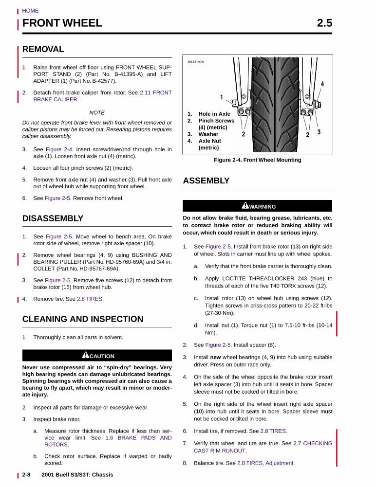
HOME
FRONT WHEEL 2.5
REMOVAL
1. Raise front wheel off floor using FRONT WHEEL SUP-PORT STAND (2) (Part No. B-41395-A) and LIFTADAPTER (1) (Part No. B-42577).
2. Detach front brake caliper from rotor. See 2.11 FRONTBRAKE CALIPER.
NOTE
Do not operate front brake lever with front wheel removed orcaliper pistons may be forced out. Reseating pistons requirescaliper disassembly.
3. See Figure 2-4. Insert screwdriver/rod through hole inaxle (1). Loosen front axle nut (4) (metric).
4. Loosen all four pinch screws (2) (metric).
5. Remove front axle nut (4) and washer (3). Pull front axleout of wheel hub while supporting front wheel.
6. See Figure 2-5. Remove front wheel.
DISASSEMBLY
1. See Figure 2-5. Move wheel to bench area. On brakerotor side of wheel, remove right axle spacer (10).
2. Remove wheel bearings (4, 9) using BUSHING ANDBEARING PULLER (Part No. HD-95760-69A) and 3/4 in.COLLET (Part No. HD-95767-69A).
3. See Figure 2-5. Remove five screws (12) to detach frontbrake rotor (15) from wheel hub.
4. Remove tire. See 2.8 TIRES.
CLEANING AND INSPECTION
1. Thoroughly clean all parts in solvent.
1CAUTION
Never use compressed air to “spin-dry” bearings. Veryhigh bearing speeds can damage unlubricated bearings.Spinning bearings with compressed air can also cause abearing to fly apart, which may result in minor or moder-ate injury.
2. Inspect all parts for damage or excessive wear.
3. Inspect brake rotor.
a. Measure rotor thickness. Replace if less than ser-vice wear limit. See 1.6 BRAKE PADS ANDROTORS.
b. Check rotor surface. Replace if warped or badlyscored.
ASSEMBLY
11WARNING1WARNING
Do not allow brake fluid, bearing grease, lubricants, etc.to contact brake rotor or reduced braking ability willoccur, which could result in death or serious injury.
1. See Figure 2-5. Install front brake rotor (13) on right sideof wheel. Slots in carrier must line up with wheel spokes.
a. Verify that the front brake carrier is thoroughly clean.
b. Apply LOCTITE THREADLOCKER 243 (blue) tothreads of each of the five T40 TORX screws (12).
c. Install rotor (13) on wheel hub using screws (12).Tighten screws in criss-cross pattern to 20-22 ft-lbs(27-30 Nm).
d. Install nut (1). Torque nut (1) to 7.5-10 ft-lbs (10-14Nm).
2. See Figure 2-5. Install spacer (8).
3. Install new wheel bearings (4, 9) into hub using suitabledriver. Press on outer race only.
4. On the side of the wheel opposite the brake rotor insertleft axle spacer (3) into hub until it seats in bore. Spacersleeve must not be cocked or tilted in bore.
5. On the right side of the wheel insert right axle spacer(10) into hub until it seats in bore. Spacer sleeve mustnot be cocked or tilted in bore.
6. Install tire, if removed. See 2.8 TIRES.
7. Verify that wheel and tire are true. See 2.7 CHECKINGCAST RIM RUNOUT.
8. Balance tire. See 2.8 TIRES, Adjustment.
Figure 2-4. Front Wheel Mounting
b0331x2x
1
2
4
2 3
1. Hole in Axle2. Pinch Screws
(4) (metric)3. Washer4. Axle Nut
(metric)
2-8 2001 Buell S3/S3T: Chassis
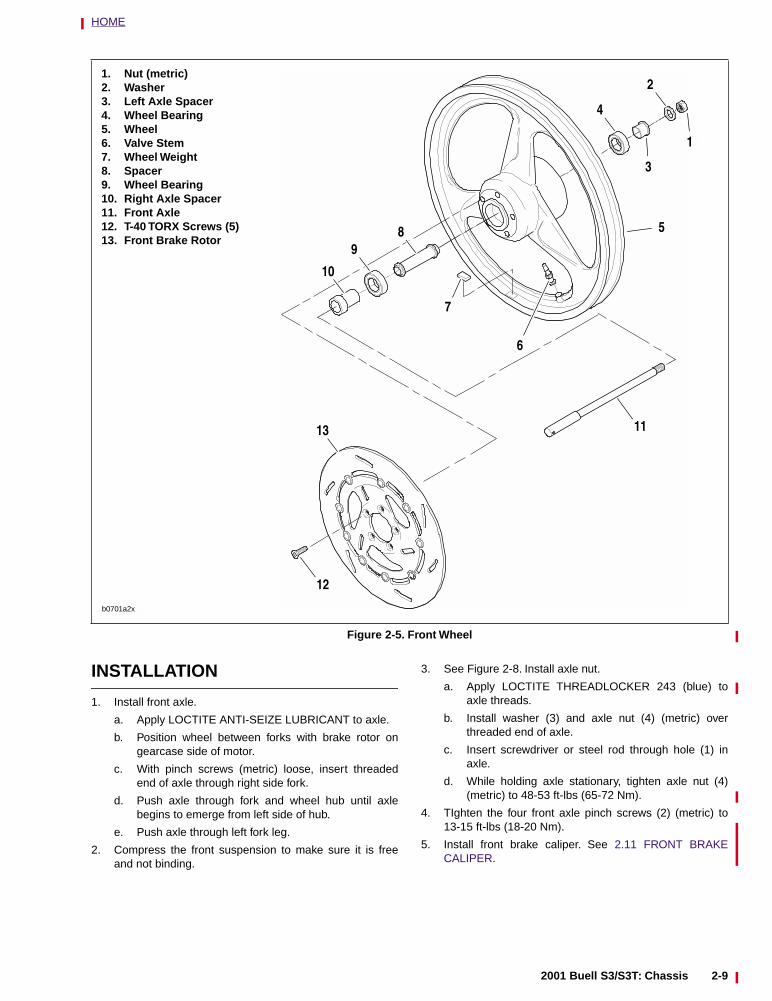
HOME
INSTALLATION
1. Install front axle.
a. Apply LOCTITE ANTI-SEIZE LUBRICANT to axle.
b. Position wheel between forks with brake rotor ongearcase side of motor.
c. With pinch screws (metric) loose, insert threadedend of axle through right side fork.
d. Push axle through fork and wheel hub until axlebegins to emerge from left side of hub.
e. Push axle through left fork leg.
2. Compress the front suspension to make sure it is freeand not binding.
3. See Figure 2-8. Install axle nut.
a. Apply LOCTITE THREADLOCKER 243 (blue) toaxle threads.
b. Install washer (3) and axle nut (4) (metric) overthreaded end of axle.
c. Insert screwdriver or steel rod through hole (1) inaxle.
d. While holding axle stationary, tighten axle nut (4)(metric) to 48-53 ft-lbs (65-72 Nm).
4. TIghten the four front axle pinch screws (2) (metric) to13-15 ft-lbs (18-20 Nm).
5. Install front brake caliper. See 2.11 FRONT BRAKECALIPER.
Figure 2-5. Front Wheel
1. Nut (metric)2. Washer3. Left Axle Spacer4. Wheel Bearing5. Wheel6. Valve Stem7. Wheel Weight8. Spacer9. Wheel Bearing10. Right Axle Spacer11. Front Axle12. T-40 TORX Screws (5)13. Front Brake Rotor
b0701a2x
1
5
3
89
10
11
12
13
2
4
6
7
2001 Buell S3/S3T: Chassis 2-9
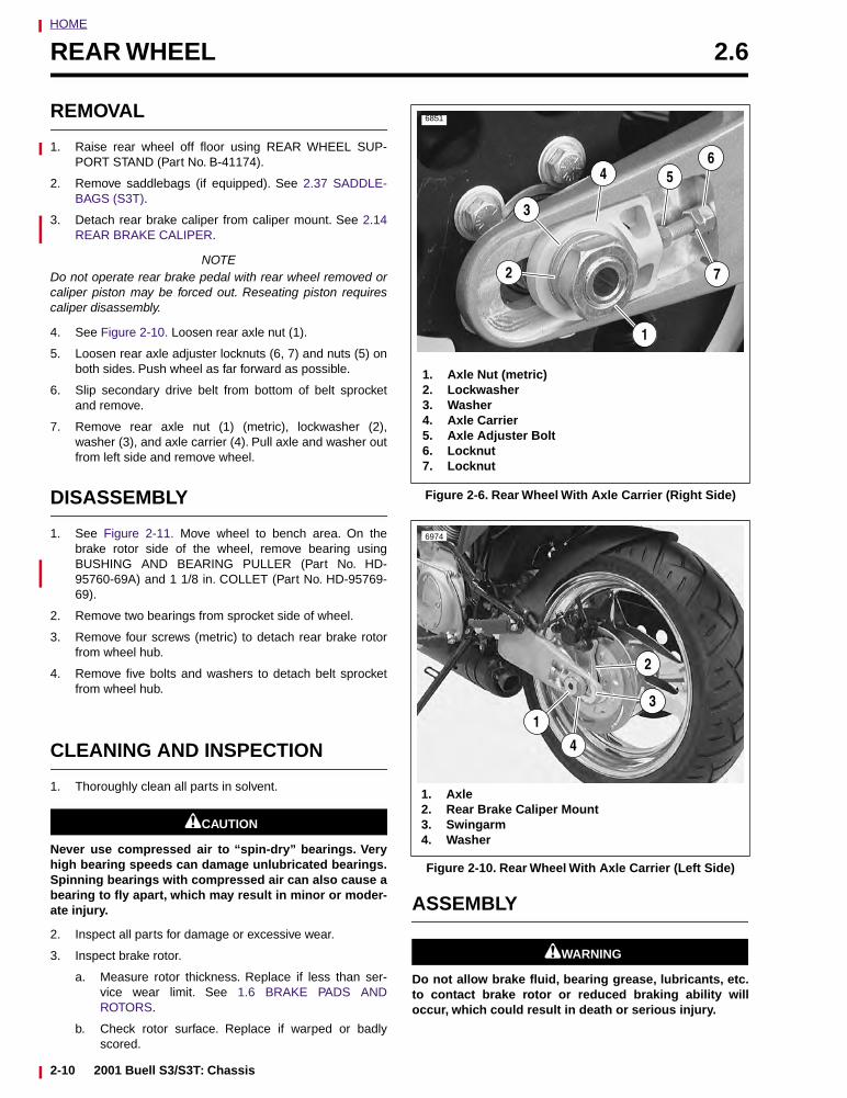
HOME
REAR WHEEL 2.6
REMOVAL
1. Raise rear wheel off floor using REAR WHEEL SUP-PORT STAND (Part No. B-41174).
2. Remove saddlebags (if equipped). See 2.37 SADDLE-BAGS (S3T).
3. Detach rear brake caliper from caliper mount. See 2.14REAR BRAKE CALIPER.
NOTEDo not operate rear brake pedal with rear wheel removed orcaliper piston may be forced out. Reseating piston requirescaliper disassembly.
4. See Figure 2-10. Loosen rear axle nut (1).
5. Loosen rear axle adjuster locknuts (6, 7) and nuts (5) onboth sides. Push wheel as far forward as possible.
6. Slip secondary drive belt from bottom of belt sprocketand remove.
7. Remove rear axle nut (1) (metric), lockwasher (2),washer (3), and axle carrier (4). Pull axle and washer outfrom left side and remove wheel.
DISASSEMBLY
1. See Figure 2-11. Move wheel to bench area. On thebrake rotor side of the wheel, remove bearing usingBUSHING AND BEARING PULLER (Part No. HD-95760-69A) and 1 1/8 in. COLLET (Part No. HD-95769-69).
2. Remove two bearings from sprocket side of wheel.
3. Remove four screws (metric) to detach rear brake rotorfrom wheel hub.
4. Remove five bolts and washers to detach belt sprocketfrom wheel hub.
CLEANING AND INSPECTION
1. Thoroughly clean all parts in solvent.
1CAUTION
Never use compressed air to “spin-dry” bearings. Veryhigh bearing speeds can damage unlubricated bearings.Spinning bearings with compressed air can also cause abearing to fly apart, which may result in minor or moder-ate injury.
2. Inspect all parts for damage or excessive wear.
3. Inspect brake rotor.
a. Measure rotor thickness. Replace if less than ser-vice wear limit. See 1.6 BRAKE PADS ANDROTORS.
b. Check rotor surface. Replace if warped or badlyscored.
ASSEMBLY
11WARNING1WARNING
Do not allow brake fluid, bearing grease, lubricants, etc.to contact brake rotor or reduced braking ability willoccur, which could result in death or serious injury.
Figure 2-6. Rear Wheel With Axle Carrier (Right Side)
Figure 2-10. Rear Wheel With Axle Carrier (Left Side)
6851
4
1. Axle Nut (metric)2. Lockwasher3. Washer4. Axle Carrier5. Axle Adjuster Bolt6. Locknut7. Locknut
1
2
3
56
7
6974
1
4
1. Axle2. Rear Brake Caliper Mount3. Swingarm4. Washer
2
3
2-10 2001 Buell S3/S3T: Chassis
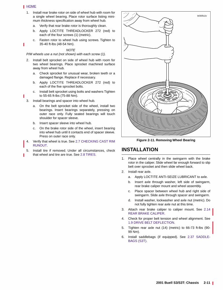
HOME
1. Install rear brake rotor on side of wheel hub with room fora single wheel bearing. Place rotor surface listing mini-mum thickness specification away from wheel hub.
a. Verify that rear brake rotor is thoroughly clean.
b. Apply LOCTITE THREADLOCKER 272 (red) toeach of the four screws (1) (metric).
c. Fasten rotor to wheel hub using screws. Tighten to35-40 ft-lbs (48-54 Nm).
NOTEP/M wheels use a nut (not shown) with each screw (1).
2. Install belt sprocket on side of wheel hub with room fortwo wheel bearings. Place sprocket machined surfaceaway from wheel hub.
a. Check sprocket for unusual wear, broken teeth or adamaged flange. Replace if necessary.
b. Apply LOCTITE THREADLOCKER 272 (red) toeach of the five sprocket bolts.
c. Install belt sprocket using bolts and washers Tightento 55-65 ft-lbs (75-88 Nm).
3. Install bearings and spacer into wheel hub.
a. On the belt sprocket side of the wheel, install twobearings. Insert bearings separately, pressing onouter race only. Fully seated bearings will touchshoulder for spacer sleeve.
b. Insert spacer sleeve into wheel hub.
c. On the brake rotor side of the wheel, insert bearinginto wheel hub until it contacts end of spacer sleeve.Press on outer race only.
4. Verify that wheel is true. See 2.7 CHECKING CAST RIMRUNOUT.
5. Install tire if removed. Under all circumstances, checkthat wheel and tire are true. See 2.8 TIRES.
INSTALLATION
1. Place wheel centrally in the swingarm with the brakerotor in the caliper. Slide wheel far enough forward to slipbelt over sprocket and then slide wheel back.
2. Install rear axle.
a. Apply LOCTITE ANTI-SEIZE LUBRICANT to axle.
b. Insert axle through washer, left side of swingarm,rear brake caliper mount and wheel assembly.
c. Place spacer between wheel hub and right side ofswingarm. Slide axle through spacer and swingarm.
d. Install washer, lockwasher and axle nut (metric). Donot fully tighten rear axle nut at this time.
3. Attach rear brake caliper to caliper mount. See 2.14REAR BRAKE CALIPER.
4. Check for proper belt tension and wheel alignment. See1.9 DRIVE BELT DEFLECTION.
5. Tighten rear axle nut (14) (metric) to 66-73 ft-lbs (90-99 Nm).
6. Install saddlebags (if equipped). See 2.37 SADDLE-BAGS (S3T).
Figure 2-11. Removing Wheel Bearing
b0305x2x
2001 Buell S3/S3T: Chassis 2-11
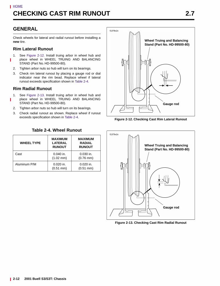
HOME
CHECKING CAST RIM RUNOUT 2.7
GENERAL
Check wheels for lateral and radial runout before installing anew tire.
Rim Lateral Runout1. See Figure 2-12. Install truing arbor in wheel hub and
place wheel in WHEEL TRUING AND BALANCINGSTAND (Part No. HD-99500-80).
2. Tighten arbor nuts so hub will turn on its bearings.
3. Check rim lateral runout by placing a gauge rod or dialindicator near the rim bead. Replace wheel if lateralrunout exceeds specification shown in Table 2-4.
Rim Radial Runout1. See Figure 2-13. Install truing arbor in wheel hub and
place wheel in WHEEL TRUING AND BALANCINGSTAND (Part No. HD-99500-80).
2. Tighten arbor nuts so hub will turn on its bearings.
3. Check radial runout as shown. Replace wheel if runoutexceeds specification shown in Table 2-4.
Table 2-4. Wheel Runout
WHEEL TYPEMAXIMUMLATERALRUNOUT
MAXIMUM RADIAL RUNOUT
Cast 0.040 in.(1.02 mm)
0.030 in.(0.76 mm)
Aluminum P/M 0.020 in.(0.51 mm)
0.020 in.(0.51 mm)
Figure 2-12. Checking Cast Rim Lateral Runout
Figure 2-13. Checking Cast Rim Radial Runout
f1378x2x
Gauge rod
Wheel Truing and Balancing Stand (Part No. HD-99500-80)
f1379x2x
Gauge rod
Wheel Truing and Balancing Stand (Part No. HD-99500-80)
2-12 2001 Buell S3/S3T: Chassis
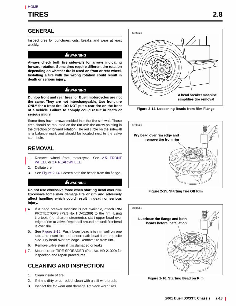
HOME
TIRES 2.8
GENERAL
Inspect tires for punctures, cuts, breaks and wear at leastweekly.
11WARNING1WARNING
Always check both tire sidewalls for arrows indicatingforward rotation. Some tires require different tire rotationdepending on whether tire is used on front or rear wheel.Installing a tire with the wrong rotation could result indeath or serious injury.
11WARNING1WARNING
Dunlop front and rear tires for Buell motorcycles are notthe same. They are not interchangeable. Use front tireONLY for a front tire. DO NOT put a rear tire on the frontof a vehicle. Failure to comply could result in death orserious injury.
Some tires have arrows molded into the tire sidewall. Thesetires should be mounted on the rim with the arrow pointing inthe direction of forward rotation. The red circle on the sidewallis a balance mark and should be located next to the valvestem hole.
REMOVAL
1. Remove wheel from motorcycle. See 2.5 FRONTWHEEL or 2.6 REAR WHEEL.
2. Deflate tire.
3. See Figure 2-14. Loosen both tire beads from rim flange.
11WARNING1WARNING
Do not use excessive force when starting bead over rim.Excessive force may damage tire or rim and adverselyaffect handling which could result in death or seriousinjury.
4. If a bead breaker machine is not available, attach RIMPROTECTORS (Part No. HD-01289) to the rim. Usingtire tools (not sharp instruments), start upper bead overedge of rim at valve. Repeat all around rim until first beadis over rim.
5. See Figure 2-15. Push lower bead into rim well on oneside and insert tire tool underneath bead from oppositeside. Pry bead over rim edge. Remove tire from rim.
6. Remove valve stem if it is damaged or leaks.
7. Mount tire on TIRE SPREADER (Part No. HD-21000) forinspection and repair procedures.
CLEANING AND INSPECTION
1. Clean inside of tire.
2. If rim is dirty or corroded, clean with a stiff wire brush.
3. Inspect tire for wear and damage. Replace worn tires.
Figure 2-14. Loosening Beads from Rim Flange
Figure 2-15. Starting Tire Off RIm
Figure 2-16. Starting Bead on Rim
A bead breaker machine simplifies tire removal
b0198x2x
Pry bead over rim edge andremove tire from rim
b0199x2x
Lubricate rim flange and bothbeads before installation
b0200x2x
2001 Buell S3/S3T: Chassis 2-13
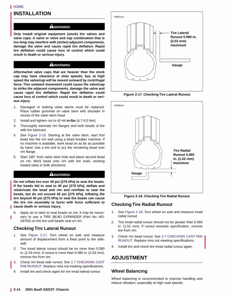
HOME
INSTALLATION
11WARNING1WARNING
Only install original equipment (stock) tire valves andvalve caps. A valve or valve and cap combination that istoo long may interfere with (strike) adjacent components,damage the valve and cause rapid tire deflation. Rapidtire deflation could cause loss of control which couldresult in death or serious injury.
11WARNING1WARNING
Aftermarket valve caps that are heavier than the stockcap may have clearance at slow speeds; but, at highspeed the valve/cap will be moved outward by centrifugalforce. This outward movement could cause the valve/capto strike the adjacent components, damage the valve andcause rapid tire deflation. Rapid tire deflation couldcause loss of control which could result in death or seri-ous injury.
1. Damaged or leaking valve stems must be replaced.Place rubber grommet on valve stem with shoulder inrecess of the valve stem head.
2. Install and tighten nut to 42-44 in-lbs (4.7-5.0 Nm).
3. Thoroughly lubricate rim flanges and both beads of tirewith tire lubricant.
4. See Figure 2-16. Starting at the valve stem, start firstbead into the rim well using a bead breaker machine. Ifno machine is available, work bead on as far as possibleby hand. Use a tire tool to pry the remaining bead overrim flange.
5. Start 180° from valve stem hole and place second beadon rim. Work bead onto rim with tire tools, workingtoward valve in both directions.
11WARNING1WARNING
Do not inflate tire over 40 psi (275 kPa) to seat the beads.If the beads fail to seat to 40 psi (275 kPa), deflate andrelubricate the bead and rim and reinflate to seat thebeads, but do not exceed 40 psi (275 kPa). Inflating thetire beyond 40 psi (275 kPa) to seat the beads can causethe tire rim assembly to burst with force sufficient tocause death or serious injury.
6. Apply air to stem to seat beads on rim. It may be neces-sary to use a TIRE BEAD EXPANDER (Part No. HD-28700) on the tire until beads seal on rim.
Checking Tire Lateral Runout1. See Figure 2-17. Turn wheel on axle and measure
amount of displacement from a fixed point to tire side-wall.
2. Tire tread lateral runout should be no more than 0.080in. (2.03 mm). If runout is more than 0.080 in. (2.03 mm),remove tire from rim.
3. Check rim bead side runout. See 2.7 CHECKING CASTRIM RUNOUT. Replace rims not meeting specifications.
4. Install tire and check again for tire tread lateral runout.
Checking Tire Radial Runout
1. See Figure 2-18. Turn wheel on axle and measure treadradial runout.
2. Tire tread radial runout should not be greater than 0.060in. (1.52 mm). If runout exceeds specification, removetire from rim.
3. Check rim bead runout. See 2.7 CHECKING CAST RIMRUNOUT. Replace rims not meeting specifications.
4. Install tire and check tire tread radial runout again.
ADJUSTMENT
Wheel Balancing
Wheel balancing is recommended to improve handling andreduce vibration, especially at high road speeds.
Figure 2-17. Checking Tire Lateral Runout
Figure 2-18. Checking Tire Radial Runout
Tire LateralRunout 0.080 in. (2.03 mm)maximum
Gauge
b0087x2x
b0088x2x
Tire Radial Runout 0.060 in. (1.52 mm)maximum
Gauge
2-14 2001 Buell S3/S3T: Chassis
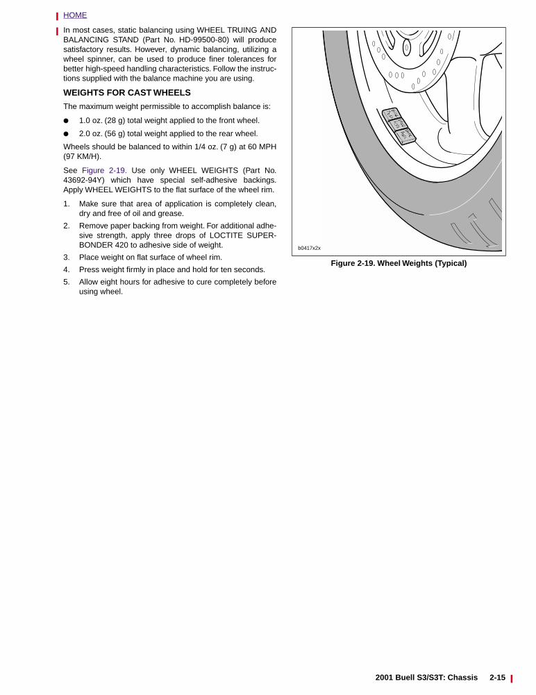
HOME
In most cases, static balancing using WHEEL TRUING ANDBALANCING STAND (Part No. HD-99500-80) will producesatisfactory results. However, dynamic balancing, utilizing awheel spinner, can be used to produce finer tolerances forbetter high-speed handling characteristics. Follow the instruc-tions supplied with the balance machine you are using.
WEIGHTS FOR CAST WHEELS
The maximum weight permissible to accomplish balance is:
● 1.0 oz. (28 g) total weight applied to the front wheel.
● 2.0 oz. (56 g) total weight applied to the rear wheel.
Wheels should be balanced to within 1/4 oz. (7 g) at 60 MPH(97 KM/H).
See Figure 2-19. Use only WHEEL WEIGHTS (Part No.43692-94Y) which have special self-adhesive backings.Apply WHEEL WEIGHTS to the flat surface of the wheel rim.
1. Make sure that area of application is completely clean,dry and free of oil and grease.
2. Remove paper backing from weight. For additional adhe-sive strength, apply three drops of LOCTITE SUPER-BONDER 420 to adhesive side of weight.
3. Place weight on flat surface of wheel rim.
4. Press weight firmly in place and hold for ten seconds.
5. Allow eight hours for adhesive to cure completely beforeusing wheel.
Figure 2-19. Wheel Weights (Typical)
b0417x2x
2001 Buell S3/S3T: Chassis 2-15
HOME
BRAKES 2.9
GENERAL
The front and rear brake systems use D.O.T. 4 BRAKEFLUID and D.O.T. 4 compatible banjo washers and rearbrake lines.
● D.O.T. 4 compatible banjo washers are black in color.
● D.O.T. 4 compatible rear brake lines have an olive drabcoating on the metal portion of the line.
The front and rear brakes are fully hydraulic disc brake sys-tems that require little maintenance. The front brake mastercylinder is an integral part of the brake hand lever assembly.The rear brake master cylinder is located on the right side ofthe motorcycle near the brake pedal.
Check the master cylinder reservoirs for proper fluid levelsafter the first 500 miles (800 km) and every 5000 miles(8000 km) thereafter. Also inspect fluid levels at the end ofevery riding season. See 1.5 BRAKES.
Check brake pads and rotors for wear at every service inter-val. See 1.5 BRAKES.
Replace D.O.T. 4 BRAKE FLUID:
● Every 2 years.
It is recommended to inspect both front and rear brake linesand replace as required:
● Every 4 years.
It is recommended to inspect both front and rear caliper andmaster cylinder seals and replace as required:
● Every 2 years.
If determining probable causes of poor brake operation, seeTable 2-5.
11WARNING1WARNING
Clean brake system components using denatured alco-hol. Do not use mineral-base cleaning solvents, such asgasoline or paint thinner. Use of mineral-base solventscauses deterioration of rubber parts that continues afterassembly. This may result in improper brake operationwhich could result in death or serious injury.
11WARNING1WARNING
Always test motorcycle brakes at low speed after servic-ing or bleeding system. To prevent death or seriousinjury, Buell recommends that all brake repairs be per-formed by a Buell dealer or other qualified technician.
11WARNING1WARNING
D.O.T. 4 brake fluid can cause irritation of eyes and skin,and may be harmful if swallowed. If large amount of fluidis swallowed, induce vomiting by administering twotablespoons of salt in a glass of warm water. Call a doc-tor. In case of contact with skin or eyes, flush with plentyof water. Get medical attention for eyes. KEEP BRAKEFLUID OUT OF THE REACH OF CHILDREN. Failure tocomply could result in death or serious injury.
11WARNING1WARNING
Never mix D.O.T. 4 with other brake fluids (such as D.O.T.5). Use only D.O.T. 4 brake fluid in motorcycles that spec-ify D.O.T. 4 fluid on the reservoir cap. Mixing differenttypes of fluid may adversely affect braking ability andlead to brake failure which could result in death or seri-ous injury.
11WARNING1WARNING
Use only fresh, uncontaminated D.O.T. 4 fluid. Cans offluid that have been opened may have been contami-nated by moisture in the air or dirt. Use of contaminatedbrake fluid may adversely affect braking ability and leadto brake failure which could result in death or seriousinjury.
11WARNING1WARNING
If rear brake line must be replaced, use only the brakeline with the olive drab coating on the metal portion ofthe line (See Parts Catalog for Part No.) with DOT 4 brakesystems. The previous black metal brake line is NOTcompatible with DOT 4 brake fluid. Failure to comply mayadversely affect braking ability and lead to brake failurewhich could result in death or serious injury.
11WARNING1WARNING
Use only new black banjo washers (See Parts Catalog forPart No.) with D.O.T. 4 brake fluid. Earlier silver banjowashers are not compatible with D.O.T. 4 fluid and willnot seal properly over time. Failure to comply mayadversely affect braking ability and lead to brake failurewhich could result in death or serious injury.
CAUTION
Cover painted surfaces and right handlebar switches anduse care when removing brake reservoir cover and add-ing D.O.T. 4 brake fluid. Spilling D.O.T. 4 brake fluid onpainted surfaces will result in cosmetic damage. Spillingbrake fluid on switches may render them inoperative.
2-16 2001 Buell S3/S3T: Chassis
HOME
Table 2-5. Brake Troubleshooting CONDITION CHECK FOR REMEDY
Excessive lever/pedal travel or spongy feel.
Air in system.
Master cylinder low on fluid.
Bleed brake(s).
Fill master cylinder with approvedbrake fluid.
Brake fade Moisture in system. Bleed brake(s).
Fill master cylinder with approvedbrake fluid.
Chattering sound when brake isapplied.
Worn pads.
Loose mounting bolts.
Warped rotor.
Replace brake pads.
Tighten bolts.
Replace rotor.
Ineffective brake –lever/pedal travels to limit.
Low fluid level.
Piston cup not functioning.
Fill master cylinder with approvedbrake fluid, and bleed system.
Rebuild cylinder.
Ineffective brake –lever/pedal travel normal.
Distorted or glazed rotor.
Distorted, glazed or contaminatedbrake pads.
Replace rotor.
Replace pads.
Brake pads drag on rotor –will not retract.
Cup in master cylinder not uncoveringrelief port.
Rear brake pedal linkage out of adjustment.
Inspect master cylinder.
Adjust linkage.
2001 Buell S3/S3T: Chassis 2-17
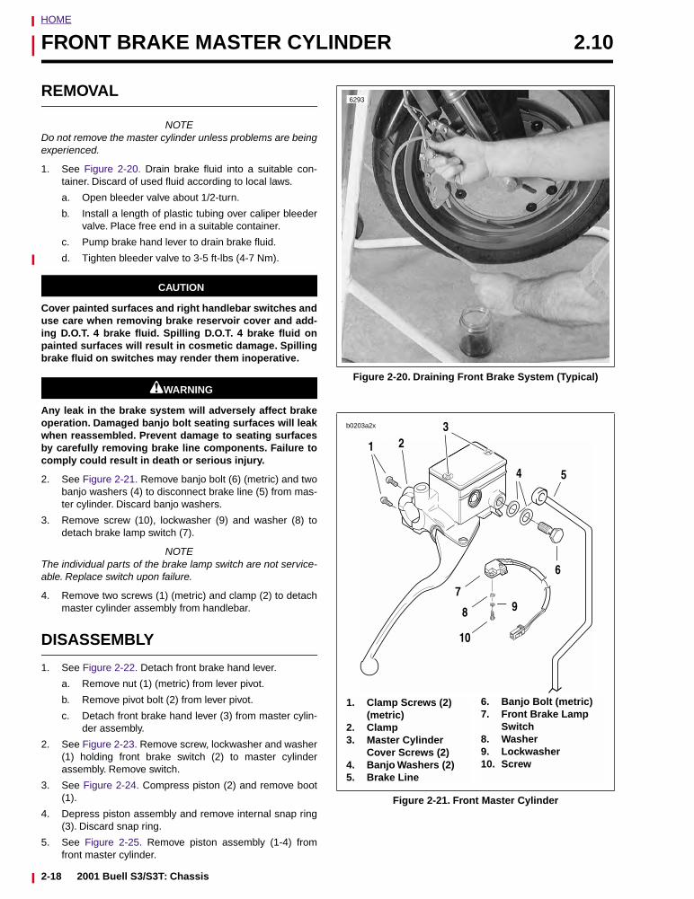
HOME
FRONT BRAKE MASTER CYLINDER 2.10
REMOVAL
NOTEDo not remove the master cylinder unless problems are beingexperienced.
1. See Figure 2-20. Drain brake fluid into a suitable con-tainer. Discard of used fluid according to local laws.
a. Open bleeder valve about 1/2-turn.
b. Install a length of plastic tubing over caliper bleedervalve. Place free end in a suitable container.
c. Pump brake hand lever to drain brake fluid.
d. Tighten bleeder valve to 3-5 ft-lbs (4-7 Nm).
CAUTION
Cover painted surfaces and right handlebar switches anduse care when removing brake reservoir cover and add-ing D.O.T. 4 brake fluid. Spilling D.O.T. 4 brake fluid onpainted surfaces will result in cosmetic damage. Spillingbrake fluid on switches may render them inoperative.
11WARNING1WARNING
Any leak in the brake system will adversely affect brakeoperation. Damaged banjo bolt seating surfaces will leakwhen reassembled. Prevent damage to seating surfacesby carefully removing brake line components. Failure tocomply could result in death or serious injury.
2. See Figure 2-21. Remove banjo bolt (6) (metric) and twobanjo washers (4) to disconnect brake line (5) from mas-ter cylinder. Discard banjo washers.
3. Remove screw (10), lockwasher (9) and washer (8) todetach brake lamp switch (7).
NOTEThe individual parts of the brake lamp switch are not service-able. Replace switch upon failure.
4. Remove two screws (1) (metric) and clamp (2) to detachmaster cylinder assembly from handlebar.
DISASSEMBLY
1. See Figure 2-22. Detach front brake hand lever.
a. Remove nut (1) (metric) from lever pivot.
b. Remove pivot bolt (2) from lever pivot.
c. Detach front brake hand lever (3) from master cylin-der assembly.
2. See Figure 2-23. Remove screw, lockwasher and washer(1) holding front brake switch (2) to master cylinderassembly. Remove switch.
3. See Figure 2-24. Compress piston (2) and remove boot(1).
4. Depress piston assembly and remove internal snap ring(3). Discard snap ring.
5. See Figure 2-25. Remove piston assembly (1-4) fromfront master cylinder.
Figure 2-20. Draining Front Brake System (Typical)
Figure 2-21. Front Master Cylinder
6293
1. Clamp Screws (2) (metric)
2. Clamp3. Master Cylinder
Cover Screws (2)4. Banjo Washers (2)5. Brake Line
6. Banjo Bolt (metric)7. Front Brake Lamp
Switch8. Washer9. Lockwasher10. Screw
b0203a2x
1
3
4
2
5
6
7
8
10
9
2-18 2001 Buell S3/S3T: Chassis
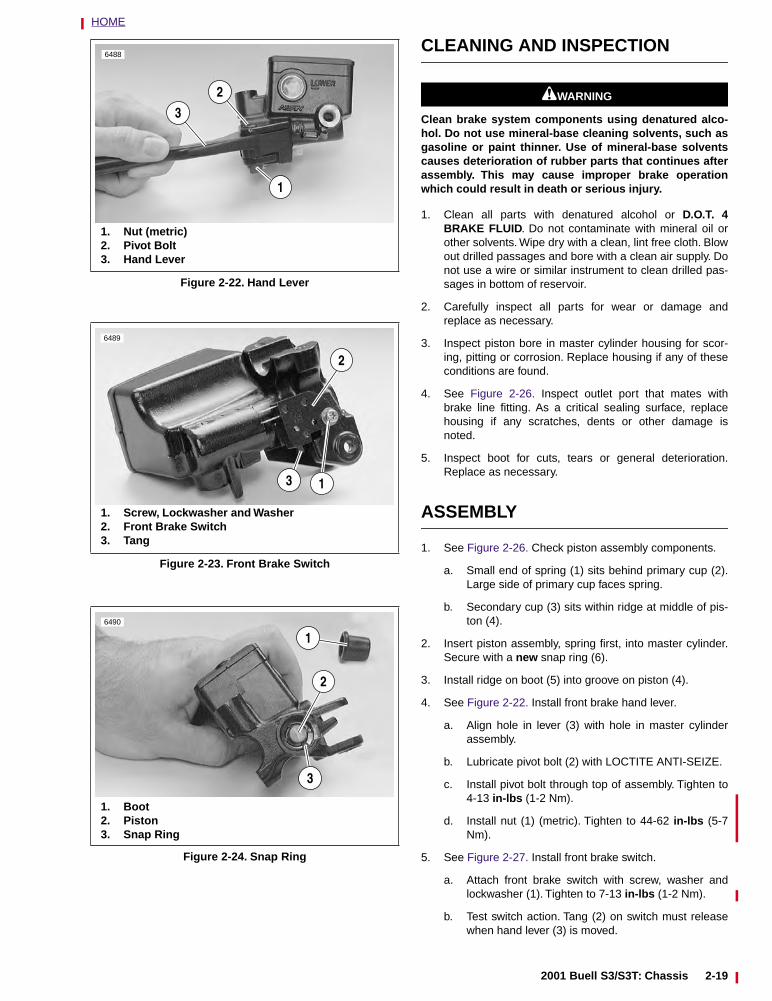
HOME
CLEANING AND INSPECTION
11WARNING1WARNING
Clean brake system components using denatured alco-hol. Do not use mineral-base cleaning solvents, such asgasoline or paint thinner. Use of mineral-base solventscauses deterioration of rubber parts that continues afterassembly. This may cause improper brake operationwhich could result in death or serious injury.
1. Clean all parts with denatured alcohol or D.O.T. 4BRAKE FLUID. Do not contaminate with mineral oil orother solvents. Wipe dry with a clean, lint free cloth. Blowout drilled passages and bore with a clean air supply. Donot use a wire or similar instrument to clean drilled pas-sages in bottom of reservoir.
2. Carefully inspect all parts for wear or damage andreplace as necessary.
3. Inspect piston bore in master cylinder housing for scor-ing, pitting or corrosion. Replace housing if any of theseconditions are found.
4. See Figure 2-26. Inspect outlet port that mates withbrake line fitting. As a critical sealing surface, replacehousing if any scratches, dents or other damage isnoted.
5. Inspect boot for cuts, tears or general deterioration.Replace as necessary.
ASSEMBLY
1. See Figure 2-26. Check piston assembly components.
a. Small end of spring (1) sits behind primary cup (2).Large side of primary cup faces spring.
b. Secondary cup (3) sits within ridge at middle of pis-ton (4).
2. Insert piston assembly, spring first, into master cylinder.Secure with a new snap ring (6).
3. Install ridge on boot (5) into groove on piston (4).
4. See Figure 2-22. Install front brake hand lever.
a. Align hole in lever (3) with hole in master cylinderassembly.
b. Lubricate pivot bolt (2) with LOCTITE ANTI-SEIZE.
c. Install pivot bolt through top of assembly. Tighten to4-13 in-lbs (1-2 Nm).
d. Install nut (1) (metric). Tighten to 44-62 in-lbs (5-7Nm).
5. See Figure 2-27. Install front brake switch.
a. Attach front brake switch with screw, washer andlockwasher (1). Tighten to 7-13 in-lbs (1-2 Nm).
b. Test switch action. Tang (2) on switch must releasewhen hand lever (3) is moved.
Figure 2-22. Hand Lever
Figure 2-23. Front Brake Switch
Figure 2-24. Snap Ring
6488
2
3
1
1. Nut (metric)2. Pivot Bolt3. Hand Lever
6489
1. Screw, Lockwasher and Washer2. Front Brake Switch3. Tang
3 1
2
6490
2
1. Boot2. Piston3. Snap Ring
3
1
2001 Buell S3/S3T: Chassis 2-19
HOME
INSTALLATION
1. See Figure 2-21. Fasten master cylinder to handlebar byinstalling clamp (2) and screws (1) (metric). Tighten to80-90 in-lbs (9-10 Nm).
11WARNING1WARNING
Use only new black banjo washers (See Parts Catalog forPart No.) with D.O.T. 4 brake fluid. Earlier silver banjowashers are not compatible with D.O.T. 4 fluid and willnot seal properly over time. Failure to comply mayadversely affect braking ability and lead to brake failurewhich could result in death or serious injury.
11WARNING1WARNING
Any leak in brake system will adversely affect brakeoperation. To avoid leakage after assembly, verify thatgaskets, banjo bolt, hydraulic brake line and bore ofmaster cylinder are completely clean. Failure to complycould result in death or serious injury.
2. Connect brake line (5) to master cylinder using two newbanjo washers (4) and banjo bolt (6) (metric). Tighten to16-20 ft-lbs (22-27 Nm).
3. Attach brake lamp switch (7) with screw (10), lockwasher(9) and washer (8).
4. Remove two master cylinder cover screws (3), cover andcover gasket.
5. See Figure 2-28. With the master cylinder in a level posi-tion, add D.O.T. 4 BRAKE FLUID. Bring fluid level towithin 1/8 in. (3.2 mm) of molded boss inside front mastercylinder reservoir.
11WARNING1WARNING
Always verify proper operation of relief port (see Step 6).A plugged or covered relief port can cause brake drag orlockup, which may cause loss of vehicle control whichcould result in death or serious injury.
6. Verify proper operation of the master cylinder relief port.Actuate the brake lever with the reservoir cover removed.A slight spurt of fluid will break the surface if all internalcomponents are working properly.
7. Attach master cylinder cover, cover gasket and plasticinsert with two cover screws. Tighten to 9-13 in-lbs (1-2Nm).
8. Bleed brake system. See 1.5 BRAKES.
11WARNING1WARNING
Check for proper brake lamp operation before ridingmotorcycle (see Step 9). Visibility is a major concern formotorcyclists. Failure to have proper brake lamp opera-tion could result in death or serious injury.
9. Turn ignition key switch to IGN. Apply brake hand lever totest brake lamp operation. Turn ignition key switch toOFF.
Figure 2-25. Piston Assembly
Figure 2-26. Master Cylinder Body
Figure 2-27. Testing Hand Lever
6491
1. Spring2. Primary Cup3. Secondary Cup4. Piston5. Boot6. Snap Ring
1 2 3 4
6
5
Outlet Port
6492
6493
1. Screw, Lockwasher and Washer2. Tang3. Hand Lever
1
23
2-20 2001 Buell S3/S3T: Chassis
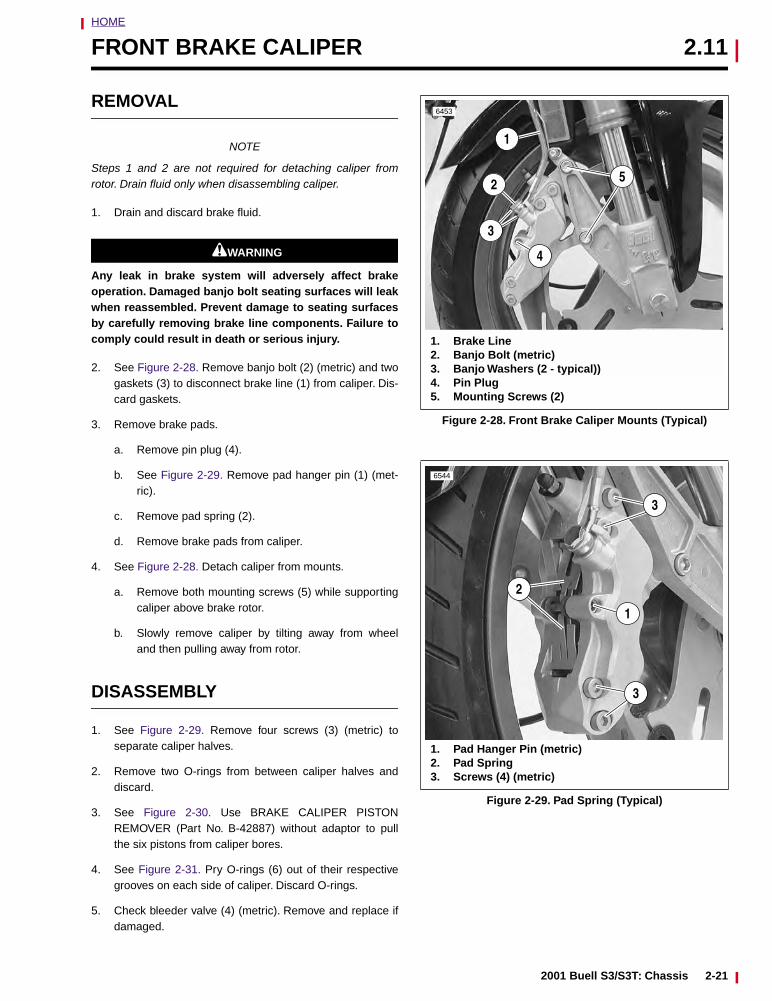
HOME
FRONT BRAKE CALIPER 2.11
REMOVAL
NOTE
Steps 1 and 2 are not required for detaching caliper fromrotor. Drain fluid only when disassembling caliper.
1. Drain and discard brake fluid.
11WARNING1WARNING
Any leak in brake system will adversely affect brakeoperation. Damaged banjo bolt seating surfaces will leakwhen reassembled. Prevent damage to seating surfacesby carefully removing brake line components. Failure tocomply could result in death or serious injury.
2. See Figure 2-28. Remove banjo bolt (2) (metric) and twogaskets (3) to disconnect brake line (1) from caliper. Dis-card gaskets.
3. Remove brake pads.
a. Remove pin plug (4).
b. See Figure 2-29. Remove pad hanger pin (1) (met-ric).
c. Remove pad spring (2).
d. Remove brake pads from caliper.
4. See Figure 2-28. Detach caliper from mounts.
a. Remove both mounting screws (5) while supportingcaliper above brake rotor.
b. Slowly remove caliper by tilting away from wheeland then pulling away from rotor.
DISASSEMBLY
1. See Figure 2-29. Remove four screws (3) (metric) toseparate caliper halves.
2. Remove two O-rings from between caliper halves anddiscard.
3. See Figure 2-30. Use BRAKE CALIPER PISTONREMOVER (Part No. B-42887) without adaptor to pullthe six pistons from caliper bores.
4. See Figure 2-31. Pry O-rings (6) out of their respectivegrooves on each side of caliper. Discard O-rings.
5. Check bleeder valve (4) (metric). Remove and replace ifdamaged.
Figure 2-28. Front Brake Caliper Mounts (Typical)
Figure 2-29. Pad Spring (Typical)
6453
52
1
3
4
1. Brake Line2. Banjo Bolt (metric)3. Banjo Washers (2 - typical))4. Pin Plug5. Mounting Screws (2)
1. Pad Hanger Pin (metric)2. Pad Spring3. Screws (4) (metric)
6544
1
2
3
3
2001 Buell S3/S3T: Chassis 2-21
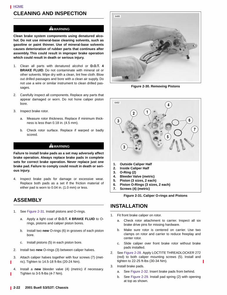
HOME
CLEANING AND INSPECTION
11WARNING1WARNING
Clean brake system components using denatured alco-hol. Do not use mineral-base cleaning solvents, such asgasoline or paint thinner. Use of mineral-base solventscauses deterioration of rubber parts that continues afterassembly. This could result in improper brake operationwhich could result in death or serious injury.
1. Clean all parts with denatured alcohol or D.O.T. 4BRAKE FLUID. Do not contaminate with mineral oil orother solvents. Wipe dry with a clean, lint free cloth. Blowout drilled passages and bore with a clean air supply. Donot use a wire or similar instrument to clean drilled pas-sages.
2. Carefully inspect all components. Replace any parts thatappear damaged or worn. Do not hone caliper pistonbore.
3. Inspect brake rotor.
a. Measure rotor thickness. Replace if minimum thick-ness is less than 0.18 in. (4.5 mm).
b. Check rotor surface. Replace if warped or badlyscored.
11WARNING1WARNING
Failure to install brake pads as a set may adversely affectbrake operation. Always replace brake pads in completesets for correct brake operation. Never replace just onebrake pad. Failure to comply could result in death or seri-ous injury.
4. Inspect brake pads for damage or excessive wear.Replace both pads as a set if the friction material ofeither pad is worn to 0.04 in. (1.0 mm) or less.
ASSEMBLY
1. See Figure 2-31. Install pistons and O-rings.
a. Apply a light coat of D.O.T. 4 BRAKE FLUID to O-rings, pistons and caliper piston bores.
b. Install two new O-rings (6) in grooves of each pistonbore.
c. Install pistons (5) in each piston bore.
2. Install two new O-rings (3) between caliper halves.
3. Attach caliper halves together with four screws (7) (met-ric). Tighten to 14.5-18 ft-lbs (20-24 Nm).
4. Install a new bleeder valve (4) (metric) if necessary.Tighten to 3-5 ft-lbs (4-7 Nm).
INSTALLATION
1. Fit front brake caliper on rotor.
a. Check rotor attachment to carrier. Inspect all sixbrake drive pins for missing hardware.
b. Make sure rotor is centered on carrier. Use twoclamps on rotor and carrier to reduce freeplay andcenter rotor.
c. Slide caliper over front brake rotor without brakepads installed.
2. See Figure 2-28. Apply LOCTITE THREADLOCKER 272(red) to both caliper mounting screws (5). Install andtighten to 22-25 ft-lbs (30-34 Nm).
3. Install brake pads.
a. See Figure 2-32. Insert brake pads from behind.
b. See Figure 2-29. Install pad spring (2) with openingat top as shown.
Figure 2-30. Removing Pistons
Figure 2-31. Caliper O-rings and Pistons
6495
6482
12
7
5
4
3
3
1. Outside Caliper Half2. Inside Caliper Half3. O-Ring (2)4. Bleeder Valve (metric)5. Piston (3 sizes, 2 each)6. Piston O-Rings (3 sizes, 2 each)7. Screws (4) (metric)
6
2-22 2001 Buell S3/S3T: Chassis
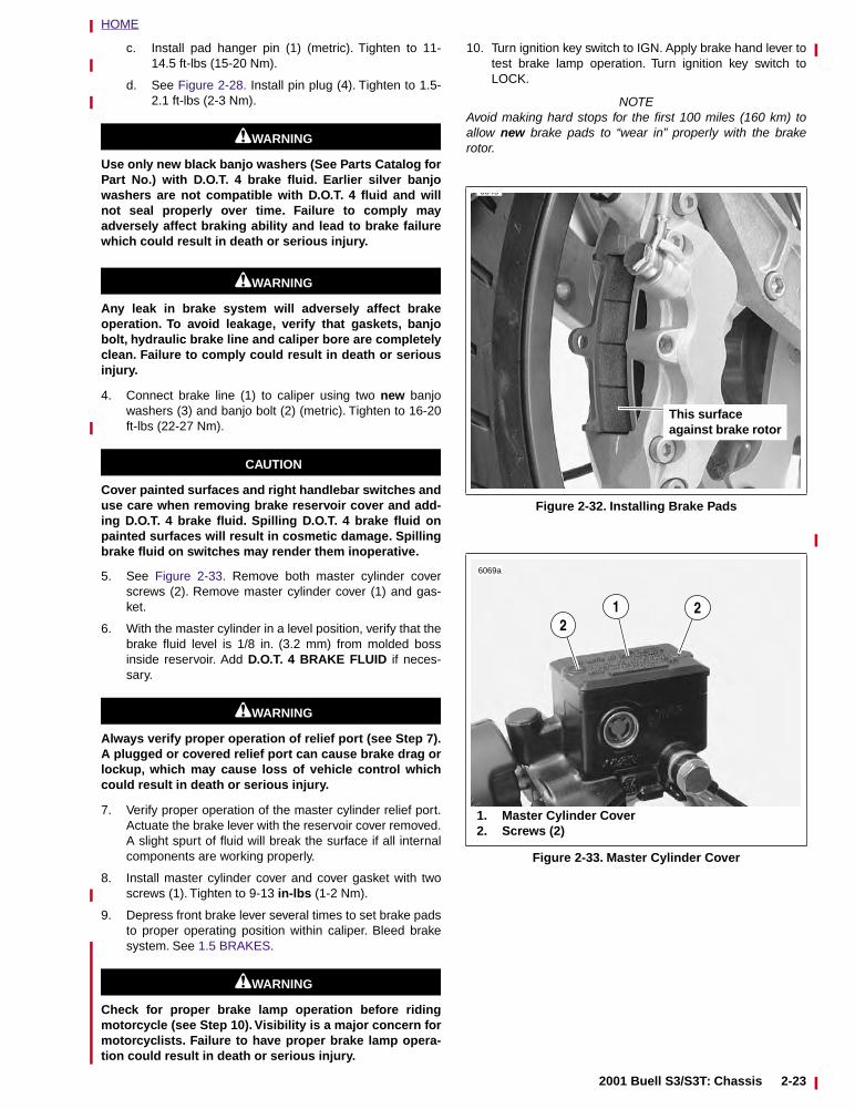
HOME
c. Install pad hanger pin (1) (metric). Tighten to 11-14.5 ft-lbs (15-20 Nm).
d. See Figure 2-28. Install pin plug (4). Tighten to 1.5-2.1 ft-lbs (2-3 Nm).
11WARNING1WARNING
Use only new black banjo washers (See Parts Catalog forPart No.) with D.O.T. 4 brake fluid. Earlier silver banjowashers are not compatible with D.O.T. 4 fluid and willnot seal properly over time. Failure to comply mayadversely affect braking ability and lead to brake failurewhich could result in death or serious injury.
11WARNING1WARNING
Any leak in brake system will adversely affect brakeoperation. To avoid leakage, verify that gaskets, banjobolt, hydraulic brake line and caliper bore are completelyclean. Failure to comply could result in death or seriousinjury.
4. Connect brake line (1) to caliper using two new banjowashers (3) and banjo bolt (2) (metric). Tighten to 16-20ft-lbs (22-27 Nm).
CAUTION
Cover painted surfaces and right handlebar switches anduse care when removing brake reservoir cover and add-ing D.O.T. 4 brake fluid. Spilling D.O.T. 4 brake fluid onpainted surfaces will result in cosmetic damage. Spillingbrake fluid on switches may render them inoperative.
5. See Figure 2-33. Remove both master cylinder coverscrews (2). Remove master cylinder cover (1) and gas-ket.
6. With the master cylinder in a level position, verify that thebrake fluid level is 1/8 in. (3.2 mm) from molded bossinside reservoir. Add D.O.T. 4 BRAKE FLUID if neces-sary.
11WARNING1WARNING
Always verify proper operation of relief port (see Step 7).A plugged or covered relief port can cause brake drag orlockup, which may cause loss of vehicle control whichcould result in death or serious injury.
7. Verify proper operation of the master cylinder relief port.Actuate the brake lever with the reservoir cover removed.A slight spurt of fluid will break the surface if all internalcomponents are working properly.
8. Install master cylinder cover and cover gasket with twoscrews (1). Tighten to 9-13 in-lbs (1-2 Nm).
9. Depress front brake lever several times to set brake padsto proper operating position within caliper. Bleed brakesystem. See 1.5 BRAKES.
11WARNING1WARNING
Check for proper brake lamp operation before ridingmotorcycle (see Step 10). Visibility is a major concern formotorcyclists. Failure to have proper brake lamp opera-tion could result in death or serious injury.
10. Turn ignition key switch to IGN. Apply brake hand lever totest brake lamp operation. Turn ignition key switch toLOCK.
NOTEAvoid making hard stops for the first 100 miles (160 km) toallow new brake pads to “wear in” properly with the brakerotor.
Figure 2-32. Installing Brake Pads
Figure 2-33. Master Cylinder Cover
6545
This surface against brake rotor
6069a
1. Master Cylinder Cover2. Screws (2)
221
2001 Buell S3/S3T: Chassis 2-23
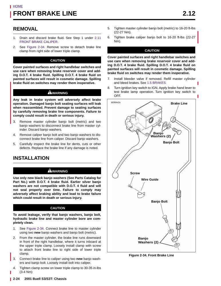
HOME
FRONT BRAKE LINE 2.12
REMOVAL
1. Drain and discard brake fluid. See Step 1 under 2.11FRONT BRAKE CALIPER.
2. See Figure 2-34. Remove screw to detach brake lineclamp from right side of lower triple clamp.
CAUTION
Cover painted surfaces and right handlebar switches anduse care when removing brake reservoir cover and add-ing D.O.T. 4 brake fluid. Spilling D.O.T. 4 brake fluid onpainted surfaces will result in cosmetic damage. Spillingbrake fluid on switches may render them inoperative.
11WARNING1WARNING
Any leak in brake system will adversely affect brakeoperation. Damaged banjo bolt seating surfaces will leakwhen reassembled. Prevent damage to seating surfacesby carefully removing brake line components. Failure tocomply could result in death or serious injury.
3. Remove master cylinder banjo bolt (metric) and twobanjo washers to disconnect brake line from master cyl-inder. Discard banjo washers.
4. Remove caliper banjo bolt and two banjo washers to dis-connect brake line from caliper. Discard banjo washers.
5. Carefully inspect the brake line for dents, cuts or otherdefects. Replace the brake line if any damage is noted.
INSTALLATION
11WARNING1WARNING
Use only new black banjo washers (See Parts Catalog forPart No.) with D.O.T. 4 brake fluid. Earlier silver banjowashers are not compatible with D.O.T. 4 fluid and willnot seal properly over time. Failure to comply mayadversely affect braking ability and lead to brake failurewhich could result in death or serious injury.
CAUTION
To avoid leakage, verify that banjo washers, banjo bolt,hydraulic brake line and master cylinder bore are com-pletely clean.
1. See Figure 2-34. Connect brake line to master cylinderusing two new banjo washers and banjo bolt (metric).
2. From the master cylinder, the brake line runs downwardin front of the right handlebar, where it turns inboard atthe upper triple clamp. Loosely install clamp with screwto attach front brake line to right side of lower tripleclamp.
3. Connect brake line to caliper using two new banjo wash-ers and banjo bolt. Loosely install bolt into caliper.
4. Tighten clamp screw on lower triple clamp to 30-35 in-lbs(3-4 Nm)
5. Tighten master cylinder banjo bolt (metric) to 16-20 ft-lbs(22-27 Nm).
6. Tighten brake caliper banjo bolt to 16-20 ft-lbs (22-27Nm).
CAUTION
Cover painted surfaces and right handlebar switches anduse care when removing brake reservoir cover and add-ing D.O.T. 4 brake fluid. Spilling D.O.T. 4 brake fluid onpainted surfaces will result in cosmetic damage. Spillingbrake fluid on switches may render them inoperative.
7. Install bleeder valve if removed. Refill master cylinderand bleed brakes. See 1.5 BRAKES
8. Turn ignition key switch to IGN. Apply brake hand lever totest brake lamp operation. Turn ignition key switch toOFF.
Figure 2-34. Front Brake Line
b0364x2x
Banjo Bolt
BanjoWashers (2)
Brake Line
Wire Guide
Banjo Bolt
BanjoWashers (2)
Screw
2-24 2001 Buell S3/S3T: Chassis
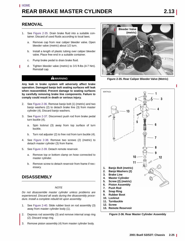
HOME
REAR BRAKE MASTER CYLINDER 2.13
REMOVAL
1. See Figure 2-35. Drain brake fluid into a suitable con-tainer. Discard of used fluids according to local laws.
a. Remove cap from rear caliper bleeder valve. Openbleeder valve (metric) about 1/2 turn.
b. Install a length of plastic tubing over caliper bleedervalve. Place free end in a suitable container.
c. Pump brake pedal to drain brake fluid.
d. Tighten bleeder valve (metric) to 3-5 ft-lbs (4-7 Nm).Reinstall cap.
11WARNING1WARNING
Any leak in brake system will adversely affect brakeoperation. Damaged banjo bolt seating surfaces will leakwhen reassembled. Prevent damage to seating surfacesby carefully removing brake line components. Failure tocomply could result in death or serious injury.
2. See Figure 2-36. Remove banjo bolt (1) (metric) and twobanjo washers (2) to detach brake line (3) from mastercylinder (4). Discard banjo washers.
3. See Figure 2-37. Disconnect push rod from brake pedalturn buckle (4).
a. Spin locknut (3) away from top surface of turnbuckle.
b. Turn rod adjuster (2) to free rod from turn buckle (4).
4. See Figure 2-38. Remove two screws (2) (metric) todetach master cylinder (3) from frame.
5. See Figure 2-39. Detach remote reservoir.
a. Remove top or bottom clamp on hose connected tomaster cylinder.
b. Remove screw to detach reservoir from frame if nec-essary.
DISASSEMBLY
NOTE
Do not disassemble master cylinder unless problems areexperienced. Discard all seals during the disassembly proce-dure. Install a complete rebuild kit upon assembly.
1. See Figure 2-40. Slide rubber boot on rod assembly (3)away from master cylinder body (1).
2. Depress rod assembly (3) and remove internal snap ring(2). Discard snap ring.
3. Remove piston assembly (4) from master cylinder body.
Figure 2-35. Rear Caliper Bleeder Valve (Metric)
Figure 2-36. Rear Master Cylinder Assembly
6483a
Bleeder Valve(metric)
1
2 3
4
6
8
7
910
11
12
13
5
1. Banjo Bolt (metric)2. Banjo Washers (2)3. Brake Line4. Master Cylinder5. Screw (2) (metric)6. Piston Assembly7. Push Rod8. Snap Ring9. Rubber Boot10. Locknut11. Turnbuckle12. Screw13. Remote Reservoir
b0474x2x
2001 Buell S3/S3T: Chassis 2-25
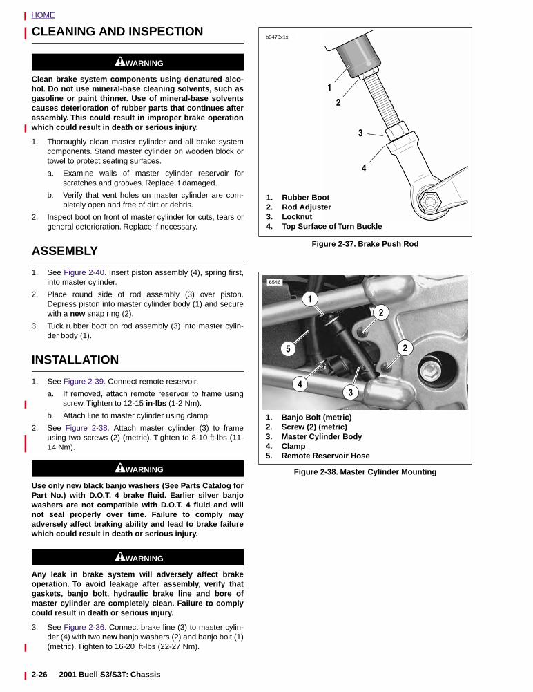
HOME
CLEANING AND INSPECTION
11WARNING1WARNING
Clean brake system components using denatured alco-hol. Do not use mineral-base cleaning solvents, such asgasoline or paint thinner. Use of mineral-base solventscauses deterioration of rubber parts that continues afterassembly. This could result in improper brake operationwhich could result in death or serious injury.
1. Thoroughly clean master cylinder and all brake systemcomponents. Stand master cylinder on wooden block ortowel to protect seating surfaces.
a. Examine walls of master cylinder reservoir forscratches and grooves. Replace if damaged.
b. Verify that vent holes on master cylinder are com-pletely open and free of dirt or debris.
2. Inspect boot on front of master cylinder for cuts, tears orgeneral deterioration. Replace if necessary.
ASSEMBLY
1. See Figure 2-40. Insert piston assembly (4), spring first,into master cylinder.
2. Place round side of rod assembly (3) over piston.Depress piston into master cylinder body (1) and securewith a new snap ring (2).
3. Tuck rubber boot on rod assembly (3) into master cylin-der body (1).
INSTALLATION
1. See Figure 2-39. Connect remote reservoir.
a. If removed, attach remote reservoir to frame usingscrew. Tighten to 12-15 in-lbs (1-2 Nm).
b. Attach line to master cylinder using clamp.
2. See Figure 2-38. Attach master cylinder (3) to frameusing two screws (2) (metric). Tighten to 8-10 ft-lbs (11-14 Nm).
11WARNING1WARNING
Use only new black banjo washers (See Parts Catalog forPart No.) with D.O.T. 4 brake fluid. Earlier silver banjowashers are not compatible with D.O.T. 4 fluid and willnot seal properly over time. Failure to comply mayadversely affect braking ability and lead to brake failurewhich could result in death or serious injury.
11WARNING1WARNING
Any leak in brake system will adversely affect brakeoperation. To avoid leakage after assembly, verify thatgaskets, banjo bolt, hydraulic brake line and bore ofmaster cylinder are completely clean. Failure to complycould result in death or serious injury.
3. See Figure 2-36. Connect brake line (3) to master cylin-der (4) with two new banjo washers (2) and banjo bolt (1)(metric). Tighten to 16-20 ft-lbs (22-27 Nm).
Figure 2-37. Brake Push Rod
Figure 2-38. Master Cylinder Mounting
b0470x1x
1. Rubber Boot2. Rod Adjuster3. Locknut4. Top Surface of Turn Buckle
1
2
3
4
6546
2
21
4
1. Banjo Bolt (metric)2. Screw (2) (metric)3. Master Cylinder Body4. Clamp5. Remote Reservoir Hose
5
3
2-26 2001 Buell S3/S3T: Chassis
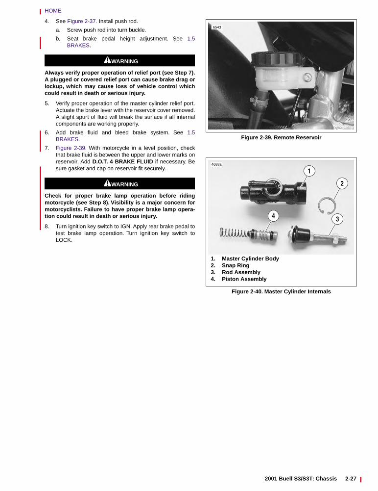
HOME
4. See Figure 2-37. Install push rod.
a. Screw push rod into turn buckle.
b. Seat brake pedal height adjustment. See 1.5BRAKES.
11WARNING1WARNING
Always verify proper operation of relief port (see Step 7).A plugged or covered relief port can cause brake drag orlockup, which may cause loss of vehicle control whichcould result in death or serious injury.
5. Verify proper operation of the master cylinder relief port.Actuate the brake lever with the reservoir cover removed.A slight spurt of fluid will break the surface if all internalcomponents are working properly.
6. Add brake fluid and bleed brake system. See 1.5BRAKES.
7. Figure 2-39. With motorcycle in a level position, checkthat brake fluid is between the upper and lower marks onreservoir. Add D.O.T. 4 BRAKE FLUID if necessary. Besure gasket and cap on reservoir fit securely.
11WARNING1WARNING
Check for proper brake lamp operation before ridingmotorcycle (see Step 8). Visibility is a major concern formotorcyclists. Failure to have proper brake lamp opera-tion could result in death or serious injury.
8. Turn ignition key switch to IGN. Apply rear brake pedal totest brake lamp operation. Turn ignition key switch toLOCK.
Figure 2-39. Remote Reservoir
Figure 2-40. Master Cylinder Internals
6543
4688a
1
2
34
1. Master Cylinder Body2. Snap Ring3. Rod Assembly4. Piston Assembly
2001 Buell S3/S3T: Chassis 2-27
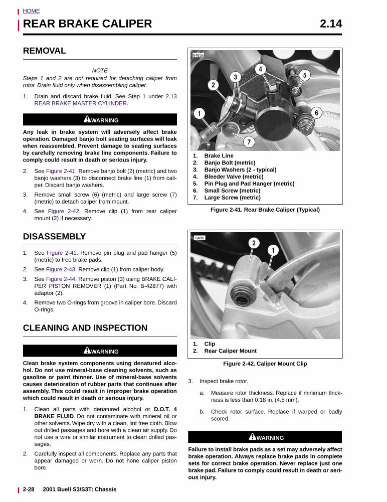
HOME
REAR BRAKE CALIPER 2.14
REMOVAL
NOTESteps 1 and 2 are not required for detaching caliper fromrotor. Drain fluid only when disassembling caliper.
1. Drain and discard brake fluid. See Step 1 under 2.13REAR BRAKE MASTER CYLINDER.
11WARNING1WARNING
Any leak in brake system will adversely affect brakeoperation. Damaged banjo bolt seating surfaces will leakwhen reassembled. Prevent damage to seating surfacesby carefully removing brake line components. Failure tocomply could result in death or serious injury.
2. See Figure 2-41. Remove banjo bolt (2) (metric) and twobanjo washers (3) to disconnect brake line (1) from cali-per. Discard banjo washers.
3. Remove small screw (6) (metric) and large screw (7)(metric) to detach caliper from mount.
4. See Figure 2-42. Remove clip (1) from rear calipermount (2) if necessary.
DISASSEMBLY
1. See Figure 2-41. Remove pin plug and pad hanger (5)(metric) to free brake pads.
2. See Figure 2-43. Remove clip (1) from caliper body.
3. See Figure 2-44. Remove piston (3) using BRAKE CALI-PER PISTON REMOVER (1) (Part No. B-42877) withadaptor (2).
4. Remove two O-rings from groove in caliper bore. DiscardO-rings.
CLEANING AND INSPECTION
11WARNING1WARNING
Clean brake system components using denatured alco-hol. Do not use mineral-base cleaning solvents, such asgasoline or paint thinner. Use of mineral-base solventscauses deterioration of rubber parts that continues afterassembly. This could result in improper brake operationwhich could result in death or serious injury.
1. Clean all parts with denatured alcohol or D.O.T. 4BRAKE FLUID. Do not contaminate with mineral oil orother solvents. Wipe dry with a clean, lint free cloth. Blowout drilled passages and bore with a clean air supply. Donot use a wire or similar instrument to clean drilled pas-sages.
2. Carefully inspect all components. Replace any parts thatappear damaged or worn. Do not hone caliper pistonbore.
3. Inspect brake rotor.
a. Measure rotor thickness. Replace if minimum thick-ness is less than 0.18 in. (4.5 mm).
b. Check rotor surface. Replace if warped or badlyscored.
11WARNING1WARNING
Failure to install brake pads as a set may adversely affectbrake operation. Always replace brake pads in completesets for correct brake operation. Never replace just onebrake pad. Failure to comply could result in death or seri-ous injury.
Figure 2-41. Rear Brake Caliper (Typical)
Figure 2-42. Caliper Mount Clip
6483a
2
4
1
1. Brake Line2. Banjo Bolt (metric)3. Banjo Washers (2 - typical)4. Bleeder Valve (metric)5. Pin Plug and Pad Hanger (metric)6. Small Screw (metric)7. Large Screw (metric)
3 5
6
7
6486
12
1. Clip2. Rear Caliper Mount
2-28 2001 Buell S3/S3T: Chassis
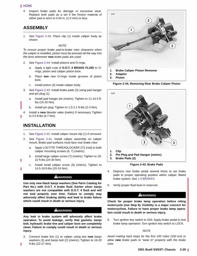
HOME
4. Inspect brake pads for damage or excessive wear.Replace both pads as a set if the friction material ofeither pad is worn to 0.04 in. (1.0 mm) or less.
ASSEMBLY
1. See Figure 2-43. Place clip (1) inside caliper body asshown.
NOTETo ensure proper brake pad-to-brake rotor clearance whenthe caliper is installed, piston must be pressed all the way intothe bore whenever new brake pads are used.
2. See Figure 2-44. Install pistons and O-rings.
a. Apply a light coat of D.O.T. 4 BRAKE FLUID to O-rings, piston and caliper piston bore.
b. Place two new O-rings inside grooves of pistonbore.
c. Install piston (3) inside caliper body.
3. See Figure 2-43. Install brake pads (3) using pad hangerand pin plug (1).
a. Install pad hanger pin (metric). Tighten to 11-14.5 ft-lbs (15-20 Nm).
b. Install pin plug. Tighten to 1.5-2.1 ft-lbs (2-3 Nm).
4. Install a new bleeder valve (metric) if necessary. Tightento 3-5 ft-lbs (4-7 Nm).
INSTALLATION
1. See Figure 2-42. Install caliper mount clip (1) if removed.
2. See Figure 2-41. Install caliper assembly on calipermount. Brake pad surfaces must face rear brake rotor.
a. Apply LOCTITE THREADLOCKER 272 (red) to bothcaliper mounting screws (6, 7) (metric).
b. Install large caliper screw (7) (metric). Tighten to 18-22 ft-lbs (24-30 Nm)
c. Install small caliper screw (6) (metric). Tighten to14.5-18 ft-lbs (20-24 Nm).
11WARNING1WARNING
Use only new black banjo washers (See Parts Catalog forPart No.) with D.O.T. 4 brake fluid. Earlier silver banjowashers are not compatible with D.O.T. 4 fluid and willnot seal properly over time. Failure to comply mayadversely affect braking ability and lead to brake failurewhich could result in death or serious injury.
11WARNING1WARNING
Any leak in brake system will adversely affect brakeoperation. To avoid leakage, verify that gaskets, banjobolt, hydraulic brake line and caliper bore are completelyclean. Failure to comply could result in death or seriousinjury.
3. Connect brake line (1) to caliper using two new banjowashers (3) and banjo bolt (2) (metric). Tighten to 16-20ft-lbs (22-27 Nm).
4. Depress rear brake pedal several times to set brakepads to proper operating position within caliper. Bleedbrake system. See 1.5 BRAKES.
5. Verify proper fluid level in reservoir.
11WARNING1WARNING
Check for proper brake lamp operation before ridingmotorcycle (see Step 6). Visibility is a major concern formotorcyclists. Failure to have proper brake lamp opera-tion could result in death or serious injury.
6. Turn ignition key switch to IGN. Apply brake pedal to testbrake lamp operation. Turn ignition key switch to LOCK.
NOTE
Avoid making hard stops for the first 100 miles (160 km) toallow new brake pads to “wear in” properly with the brakerotor.
Figure 2-44. Removing Rear Brake Caliper Piston
Figure 2-43. Brake Pads
6487
1
1. Brake Caliper Piston Remover2. Adaptor3. Piston
2
3
6487
3
1
2
1. Clip2. Pin Plug and Pad Hanger (metric)3. Brake Pads (2)
2001 Buell S3/S3T: Chassis 2-29
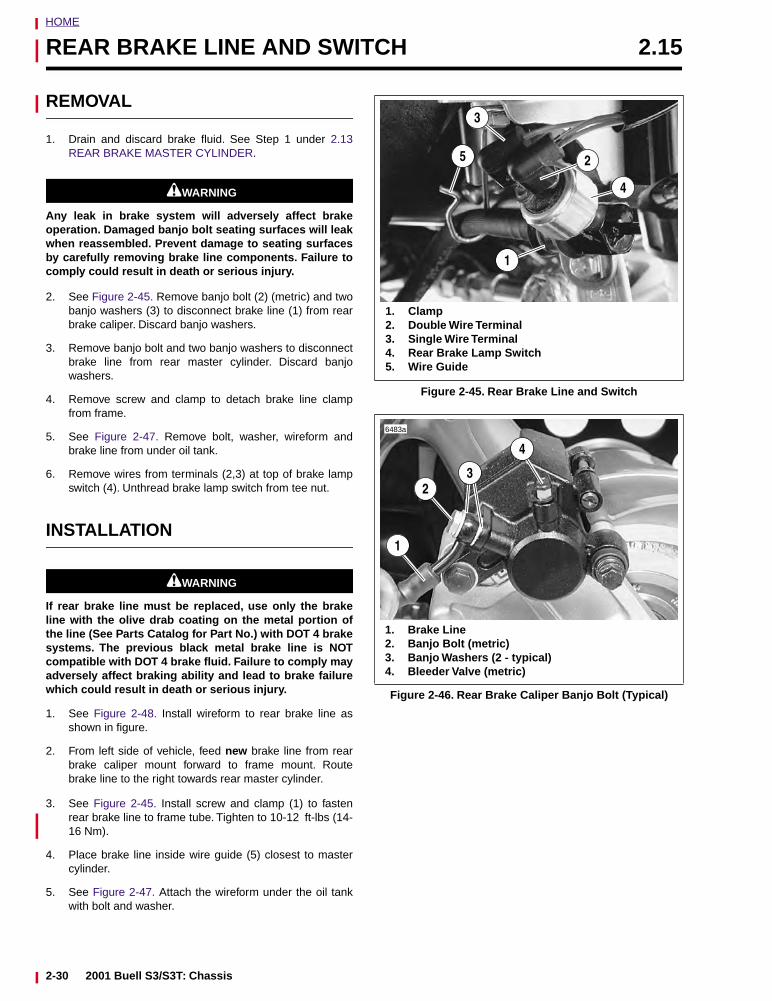
HOME
REAR BRAKE LINE AND SWITCH 2.15
REMOVAL
1. Drain and discard brake fluid. See Step 1 under 2.13REAR BRAKE MASTER CYLINDER.
11WARNING1WARNING
Any leak in brake system will adversely affect brakeoperation. Damaged banjo bolt seating surfaces will leakwhen reassembled. Prevent damage to seating surfacesby carefully removing brake line components. Failure tocomply could result in death or serious injury.
2. See Figure 2-45. Remove banjo bolt (2) (metric) and twobanjo washers (3) to disconnect brake line (1) from rearbrake caliper. Discard banjo washers.
3. Remove banjo bolt and two banjo washers to disconnectbrake line from rear master cylinder. Discard banjowashers.
4. Remove screw and clamp to detach brake line clampfrom frame.
5. See Figure 2-47. Remove bolt, washer, wireform andbrake line from under oil tank.
6. Remove wires from terminals (2,3) at top of brake lampswitch (4). Unthread brake lamp switch from tee nut.
INSTALLATION
11WARNING1WARNING
If rear brake line must be replaced, use only the brakeline with the olive drab coating on the metal portion ofthe line (See Parts Catalog for Part No.) with DOT 4 brakesystems. The previous black metal brake line is NOTcompatible with DOT 4 brake fluid. Failure to comply mayadversely affect braking ability and lead to brake failurewhich could result in death or serious injury.
1. See Figure 2-48. Install wireform to rear brake line asshown in figure.
2. From left side of vehicle, feed new brake line from rearbrake caliper mount forward to frame mount. Routebrake line to the right towards rear master cylinder.
3. See Figure 2-45. Install screw and clamp (1) to fastenrear brake line to frame tube. Tighten to 10-12 ft-lbs (14-16 Nm).
4. Place brake line inside wire guide (5) closest to mastercylinder.
5. See Figure 2-47. Attach the wireform under the oil tankwith bolt and washer.
Figure 2-45. Rear Brake Line and Switch
Figure 2-46. Rear Brake Caliper Banjo Bolt (Typical)
1
3
4
1. Clamp2. Double Wire Terminal3. Single Wire Terminal4. Rear Brake Lamp Switch5. Wire Guide
25
6483a
2
4
1
1. Brake Line2. Banjo Bolt (metric)3. Banjo Washers (2 - typical)4. Bleeder Valve (metric)
3
2-30 2001 Buell S3/S3T: Chassis
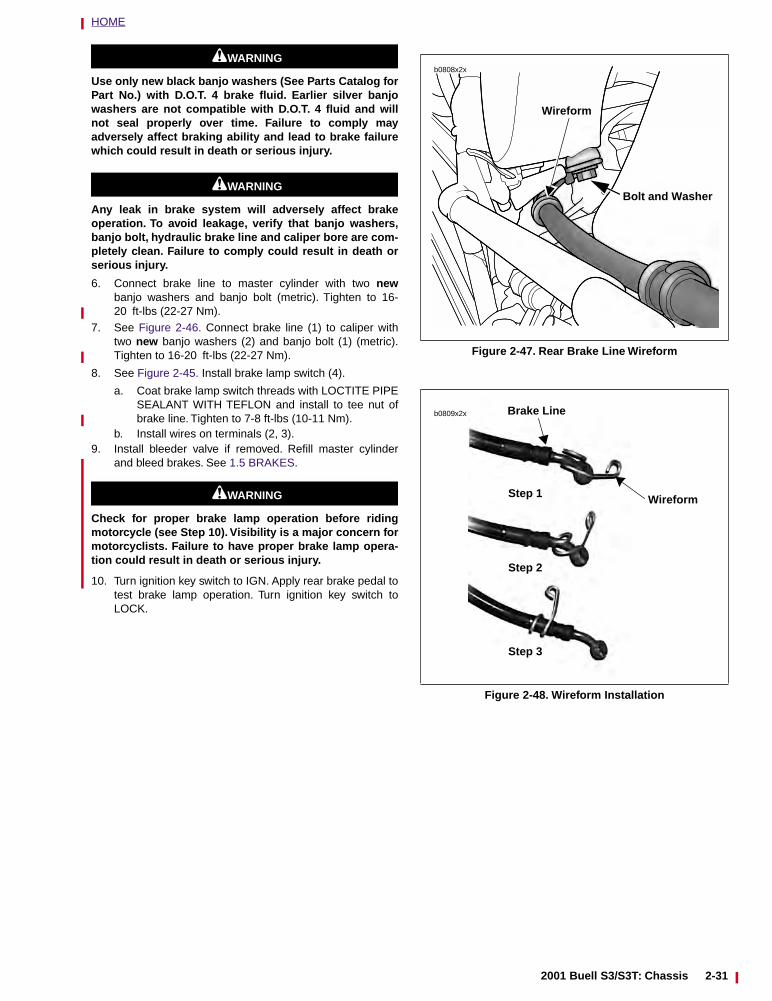
HOME
11WARNING1WARNING
Use only new black banjo washers (See Parts Catalog forPart No.) with D.O.T. 4 brake fluid. Earlier silver banjowashers are not compatible with D.O.T. 4 fluid and willnot seal properly over time. Failure to comply mayadversely affect braking ability and lead to brake failurewhich could result in death or serious injury.
11WARNING1WARNING
Any leak in brake system will adversely affect brakeoperation. To avoid leakage, verify that banjo washers,banjo bolt, hydraulic brake line and caliper bore are com-pletely clean. Failure to comply could result in death orserious injury.
6. Connect brake line to master cylinder with two newbanjo washers and banjo bolt (metric). Tighten to 16-20 ft-lbs (22-27 Nm).
7. See Figure 2-46. Connect brake line (1) to caliper withtwo new banjo washers (2) and banjo bolt (1) (metric).Tighten to 16-20 ft-lbs (22-27 Nm).
8. See Figure 2-45. Install brake lamp switch (4).
a. Coat brake lamp switch threads with LOCTITE PIPESEALANT WITH TEFLON and install to tee nut ofbrake line. Tighten to 7-8 ft-lbs (10-11 Nm).
b. Install wires on terminals (2, 3).9. Install bleeder valve if removed. Refill master cylinder
and bleed brakes. See 1.5 BRAKES.
11WARNING1WARNING
Check for proper brake lamp operation before ridingmotorcycle (see Step 10). Visibility is a major concern formotorcyclists. Failure to have proper brake lamp opera-tion could result in death or serious injury.
10. Turn ignition key switch to IGN. Apply rear brake pedal totest brake lamp operation. Turn ignition key switch toLOCK.
Figure 2-47. Rear Brake Line Wireform
Figure 2-48. Wireform Installation
b0808x2x
Bolt and Washer
Wireform
b0809x2x
Wireform
Brake Line
Step 1
Step 2
Step 3
2001 Buell S3/S3T: Chassis 2-31
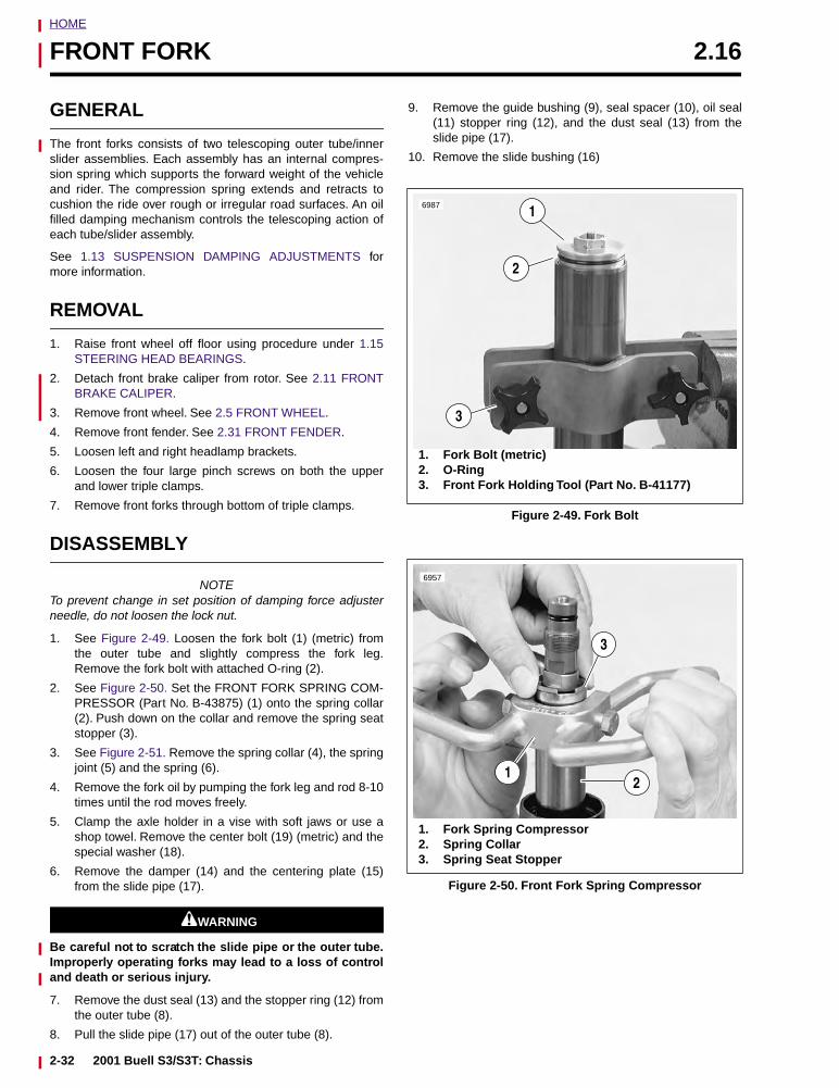
HOME
FRONT FORK 2.16
GENERAL
The front forks consists of two telescoping outer tube/innerslider assemblies. Each assembly has an internal compres-sion spring which supports the forward weight of the vehicleand rider. The compression spring extends and retracts tocushion the ride over rough or irregular road surfaces. An oilfilled damping mechanism controls the telescoping action ofeach tube/slider assembly.
See 1.13 SUSPENSION DAMPING ADJUSTMENTS formore information.
REMOVAL
1. Raise front wheel off floor using procedure under 1.15STEERING HEAD BEARINGS.
2. Detach front brake caliper from rotor. See 2.11 FRONTBRAKE CALIPER.
3. Remove front wheel. See 2.5 FRONT WHEEL.
4. Remove front fender. See 2.31 FRONT FENDER.
5. Loosen left and right headlamp brackets.
6. Loosen the four large pinch screws on both the upperand lower triple clamps.
7. Remove front forks through bottom of triple clamps.
DISASSEMBLY
NOTETo prevent change in set position of damping force adjusterneedle, do not loosen the lock nut.
1. See Figure 2-49. Loosen the fork bolt (1) (metric) fromthe outer tube and slightly compress the fork leg.Remove the fork bolt with attached O-ring (2).
2. See Figure 2-50. Set the FRONT FORK SPRING COM-PRESSOR (Part No. B-43875) (1) onto the spring collar(2). Push down on the collar and remove the spring seatstopper (3).
3. See Figure 2-51. Remove the spring collar (4), the springjoint (5) and the spring (6).
4. Remove the fork oil by pumping the fork leg and rod 8-10times until the rod moves freely.
5. Clamp the axle holder in a vise with soft jaws or use ashop towel. Remove the center bolt (19) (metric) and thespecial washer (18).
6. Remove the damper (14) and the centering plate (15)from the slide pipe (17).
11WARNING1WARNING
Be careful not to scratch the slide pipe or the outer tube.Improperly operating forks may lead to a loss of controland death or serious injury.
7. Remove the dust seal (13) and the stopper ring (12) fromthe outer tube (8).
8. Pull the slide pipe (17) out of the outer tube (8).
9. Remove the guide bushing (9), seal spacer (10), oil seal(11) stopper ring (12), and the dust seal (13) from theslide pipe (17).
10. Remove the slide bushing (16)
Figure 2-49. Fork Bolt
Figure 2-50. Front Fork Spring Compressor
6987 1
2
3
1. Fork Bolt (metric)2. O-Ring3. Front Fork Holding Tool (Part No. B-41177)
6957
3
12
1. Fork Spring Compressor2. Spring Collar3. Spring Seat Stopper
2-32 2001 Buell S3/S3T: Chassis
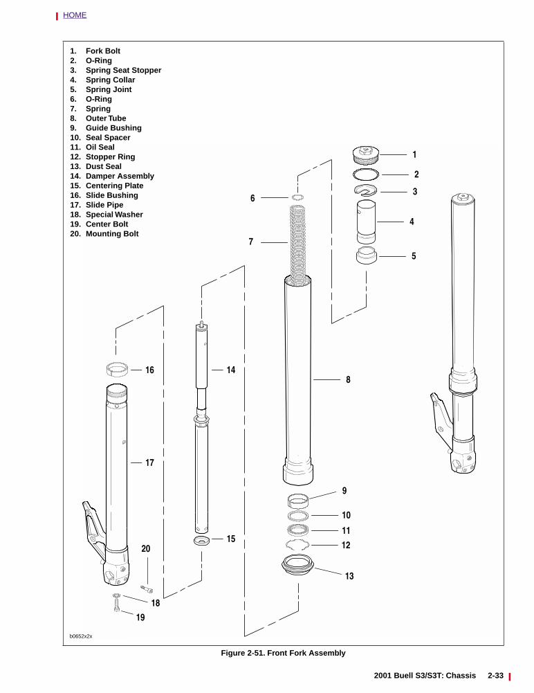
HOME
Figure 2-51. Front Fork Assembly
36
1
2
4
5
1. Fork Bolt2. O-Ring3. Spring Seat Stopper4. Spring Collar5. Spring Joint6. O-Ring7. Spring8. Outer Tube9. Guide Bushing10. Seal Spacer11. Oil Seal12. Stopper Ring13. Dust Seal14. Damper Assembly15. Centering Plate16. Slide Bushing17. Slide Pipe18. Special Washer19. Center Bolt20. Mounting Bolt
8
9
10
11
12
13
7
16
18
19
20
b0652x2x
17
14
15
2001 Buell S3/S3T: Chassis 2-33
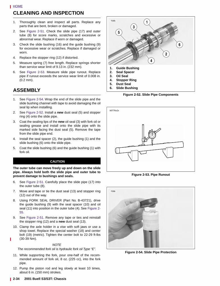
HOME
CLEANING AND INSPECTION
1. Thoroughly clean and inspect all parts. Replace anyparts that are bent, broken or damaged.
2. See Figure 2-51. Check the slide pipe (17) and outertube (8) for score marks, scratches and excessive orabnormal wear. Replace if worn or damaged.
3. Check the slide bushing (16) and the guide bushing (9)for excessive wear or scratches. Replace if damaged orworn.
4. Replace the stopper ring (12) if distorted.
5. Measure spring (7) free length. Replace springs shorterthan service wear limit of 9.13 in. (232 mm).
6. See Figure 2-53. Measure slide pipe runout. Replacepipe if runout exceeds the service wear limit of 0.008 in.(0.2 mm).
ASSEMBLY
1. See Figure 2-54. Wrap the end of the slide pipe and theslide bushing channel with tape to avoid damaging the oilseal lip when installing.
2. See Figure 2-52. Install a new dust seal (5) and stopperring (4) onto the slide pipe.
3. Coat the sealing lips of the new oil seal (3) with fork oil orsealing grease and install onto the slide pipe with itsmarked side facing the dust seal (5). Remove the tapefrom the slide pipe end.
4. Install the seal spacer (2), the guide bushing (1) and theslide bushing (6) onto the slide pipe.
5. Coat the slide bushing (6) and the guide bushing (1) withfork oil.
CAUTION
The outer tube can move freely up and down on the slidepipe. Always hold both the slide pipe and outer tube toprevent damage to bushings and seals.
6. See Figure 2-51. Carefully place the slide pipe (17) intothe outer tube (8).
7. Move and tape or tie the dust seal (13) and stopper ring(12) out of the way.
8. Using FORK SEAL DRIVER (Part No. B-43721), drivethe guide bushing (9) with the seal spacer (10) and oilseal (11) into position in the outer tube (4). See Figure 2-55.
9. See Figure 2-51. Remove any tape or ties and reinstallthe stopper ring (12) and a new dust seal (13).
10. Clamp the axle holder in a vise with soft jaws or use ashop towel. Replace the special washer (18) and centerbolt (19) (metric). Tighten the center bolt to 22-29 ft-lbs(30-39 Nm).
NOTEThe recommended fork oil is hydraulic fork oil Type “E”.
11. While supporting the fork, pour one-half of the recom-mended amount of fork oil, 8 oz. (225 cc), into the forkpipe.
12. Pump the piston rod and leg slowly at least 10 times,about 6 in. (150 mm) strokes.
Figure 2-52. Slide Pipe Components
Figure 2-53. Pipe Runout
Figure 2-54. Slide Pipe Protection
1. Guide Bushing2. Seal Spacer3. Oil Seal4. Stopper Ring5. Dust Seal6. Slide Bushing
5
7095
31
4
2
6
b0776x2x
7096
2-34 2001 Buell S3/S3T: Chassis
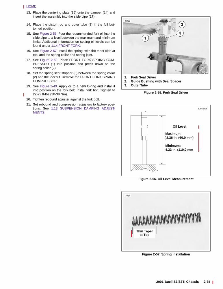
HOME
13. Place the centering plate (15) onto the damper (14) andinsert the assembly into the slide pipe (17).
14. Place the piston rod and outer tube (8) in the full bot-tomed position.
15. See Figure 2-56. Pour the recommended fork oil into theslide pipe to a level between the maximum and minimumlimits. Additional information on setting oil levels can befound under 1.14 FRONT FORK.
16. See Figure 2-57. Install the spring, with the taper side attop, and the spring collar and spring joint.
17. See Figure 2-50. Place FRONT FORK SPRING COM-PRESSOR (1) into position and press down on thespring collar (2).
18. Set the spring seat stopper (3) between the spring collar(2) and the locknut. Remove the FRONT FORK SPRINGCOMPRESSOR.
19. See Figure 2-49. Apply oil to a new O-ring and install itinto position on the fork bolt. Install fork bolt. Tighten to22-29 ft-lbs (30-39 Nm).
20. Tighten rebound adjuster against the fork bolt.
21. Set rebound and compression adjusters to factory posi-tions. See 1.13 SUSPENSION DAMPING ADJUST-MENTS.
Figure 2-55. Fork Seal Driver
Figure 2-56. Oil Level Measurement
Figure 2-57. Spring Installation
1. Fork Seal Driver2. Guide Bushing with Seal Spacer3. Outer Tube
13
6958
2
Oil Level:
Maximum: )2.36 in. (60.0 mm)
Minimum:4.33 in. (110.0 mm
b0666x2x
Thin Taper at Top
7097
2001 Buell S3/S3T: Chassis 2-35
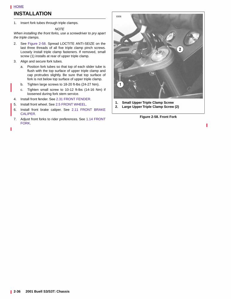
HOME
INSTALLATION
1. Insert fork tubes through triple clamps.
NOTEWhen installing the front forks, use a screwdriver to pry apartthe triple clamps.
2. See Figure 2-58. Spread LOCTITE ANTI-SEIZE on thelast three threads of all five triple clamp pinch screws.Loosely install triple clamp fasteners. If removed, smallscrew (1) installs at rear of upper triple clamp.
3. Align and secure fork tubes.
a. Position fork tubes so that top of each slider tube isflush with the top surface of upper triple clamp andcap protrudes slightly. Be sure that top surface offork is not below top surface of upper triple clamp.
b. Tighten large screws to 18-20 ft-lbs (24-27 Nm).
c. Tighten small screw to 10-12 ft-lbs (14-16 Nm) ifloosened during fork stem service.
4. Install front fender. See 2.31 FRONT FENDER.
5. Install front wheel. See 2.5 FRONT WHEEL.
6. Install front brake caliper. See 2.11 FRONT BRAKECALIPER.
7. Adjust front forks to rider preferences. See 1.14 FRONTFORK.
Figure 2-58. Front Fork
8306
1. Small Upper Triple Clamp Screw2. Large Upper Triple Clamp Screw (2)
2
1
2-36 2001 Buell S3/S3T: Chassis
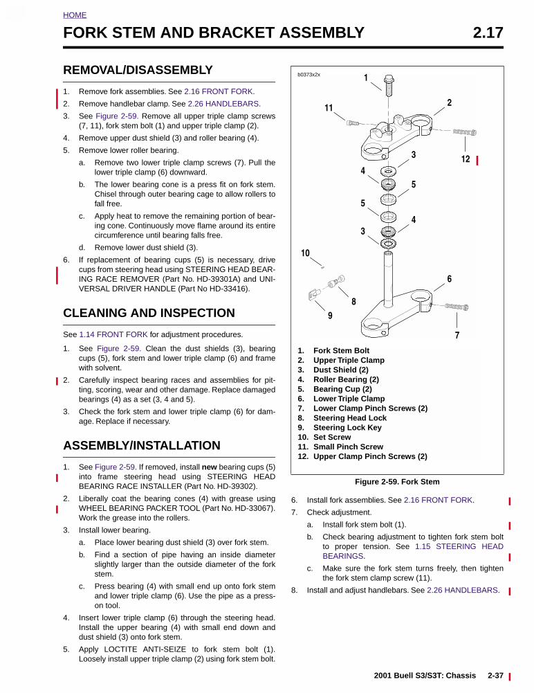
HOME
2
FORK STEM AND BRACKET ASSEMBLY 2.17
REMOVAL/DISASSEMBLY
1. Remove fork assemblies. See 2.16 FRONT FORK.
2. Remove handlebar clamp. See 2.26 HANDLEBARS.
3. See Figure 2-59. Remove all upper triple clamp screws(7, 11), fork stem bolt (1) and upper triple clamp (2).
4. Remove upper dust shield (3) and roller bearing (4).
5. Remove lower roller bearing.
a. Remove two lower triple clamp screws (7). Pull thelower triple clamp (6) downward.
b. The lower bearing cone is a press fit on fork stem.Chisel through outer bearing cage to allow rollers tofall free.
c. Apply heat to remove the remaining portion of bear-ing cone. Continuously move flame around its entirecircumference until bearing falls free.
d. Remove lower dust shield (3).
6. If replacement of bearing cups (5) is necessary, drivecups from steering head using STEERING HEAD BEAR-ING RACE REMOVER (Part No. HD-39301A) and UNI-VERSAL DRIVER HANDLE (Part No HD-33416).
CLEANING AND INSPECTION
See 1.14 FRONT FORK for adjustment procedures.
1. See Figure 2-59. Clean the dust shields (3), bearingcups (5), fork stem and lower triple clamp (6) and framewith solvent.
2. Carefully inspect bearing races and assemblies for pit-ting, scoring, wear and other damage. Replace damagedbearings (4) as a set (3, 4 and 5).
3. Check the fork stem and lower triple clamp (6) for dam-age. Replace if necessary.
ASSEMBLY/INSTALLATION
1. See Figure 2-59. If removed, install new bearing cups (5)into frame steering head using STEERING HEADBEARING RACE INSTALLER (Part No. HD-39302).
2. Liberally coat the bearing cones (4) with grease usingWHEEL BEARING PACKER TOOL (Part No. HD-33067).Work the grease into the rollers.
3. Install lower bearing.
a. Place lower bearing dust shield (3) over fork stem.
b. Find a section of pipe having an inside diameterslightly larger than the outside diameter of the forkstem.
c. Press bearing (4) with small end up onto fork stemand lower triple clamp (6). Use the pipe as a press-on tool.
4. Insert lower triple clamp (6) through the steering head.Install the upper bearing (4) with small end down anddust shield (3) onto fork stem.
5. Apply LOCTITE ANTI-SEIZE to fork stem bolt (1).Loosely install upper triple clamp (2) using fork stem bolt.
6. Install fork assemblies. See 2.16 FRONT FORK.
7. Check adjustment.
a. Install fork stem bolt (1).
b. Check bearing adjustment to tighten fork stem boltto proper tension. See 1.15 STEERING HEADBEARINGS.
c. Make sure the fork stem turns freely, then tightenthe fork stem clamp screw (11).
8. Install and adjust handlebars. See 2.26 HANDLEBARS.
Figure 2-59. Fork Stem
1. Fork Stem Bolt2. Upper Triple Clamp3. Dust Shield (2)4. Roller Bearing (2)5. Bearing Cup (2)6. Lower Triple Clamp7. Lower Clamp Pinch Screws (2)8. Steering Head Lock9. Steering Lock Key10. Set Screw11. Small Pinch Screw12. Upper Clamp Pinch Screws (2)
b0373x2x
2
12
11
1
3
5
4
4
5
3
6
89
10
7
2001 Buell S3/S3T: Chassis 2-37
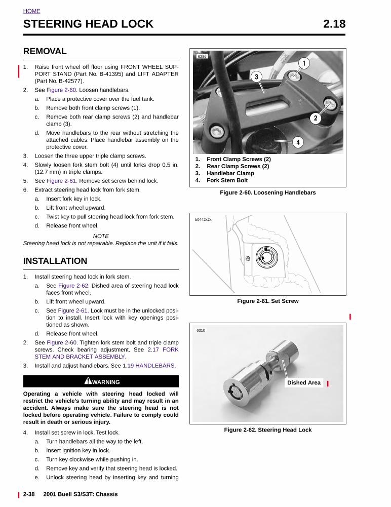
HOME
STEERING HEAD LOCK 2.18
REMOVAL
1. Raise front wheel off floor using FRONT WHEEL SUP-PORT STAND (Part No. B-41395) and LIFT ADAPTER(Part No. B-42577).
2. See Figure 2-60. Loosen handlebars.
a. Place a protective cover over the fuel tank.
b. Remove both front clamp screws (1).
c. Remove both rear clamp screws (2) and handlebarclamp (3).
d. Move handlebars to the rear without stretching theattached cables. Place handlebar assembly on theprotective cover.
3. Loosen the three upper triple clamp screws.
4. Slowly loosen fork stem bolt (4) until forks drop 0.5 in.(12.7 mm) in triple clamps.
5. See Figure 2-61. Remove set screw behind lock.
6. Extract steering head lock from fork stem.
a. Insert fork key in lock.
b. Lift front wheel upward.
c. Twist key to pull steering head lock from fork stem.
d. Release front wheel.
NOTESteering head lock is not repairable. Replace the unit if it fails.
INSTALLATION
1. Install steering head lock in fork stem.
a. See Figure 2-62. Dished area of steering head lockfaces front wheel.
b. Lift front wheel upward.
c. See Figure 2-61. Lock must be in the unlocked posi-tion to install. Insert lock with key openings posi-tioned as shown.
d. Release front wheel.
2. See Figure 2-60. Tighten fork stem bolt and triple clampscrews. Check bearing adjustment. See 2.17 FORKSTEM AND BRACKET ASSEMBLY.
3. Install and adjust handlebars. See 1.19 HANDLEBARS.
11WARNING1WARNING
Operating a vehicle with steering head locked willrestrict the vehicle’s turning ability and may result in anaccident. Always make sure the steering head is notlocked before operating vehicle. Failure to comply couldresult in death or serious injury.
4. Install set screw in lock. Test lock.
a. Turn handlebars all the way to the left.
b. Insert ignition key in lock.
c. Turn key clockwise while pushing in.
d. Remove key and verify that steering head is locked.
e. Unlock steering head by inserting key and turning
Figure 2-60. Loosening Handlebars
Figure 2-61. Set Screw
Figure 2-62. Steering Head Lock
6286
1. Front Clamp Screws (2)2. Rear Clamp Screws (2)3. Handlebar Clamp4. Fork Stem Bolt
2
1
3
4
b0442x2x
Dished Area
6310
2-38 2001 Buell S3/S3T: Chassis
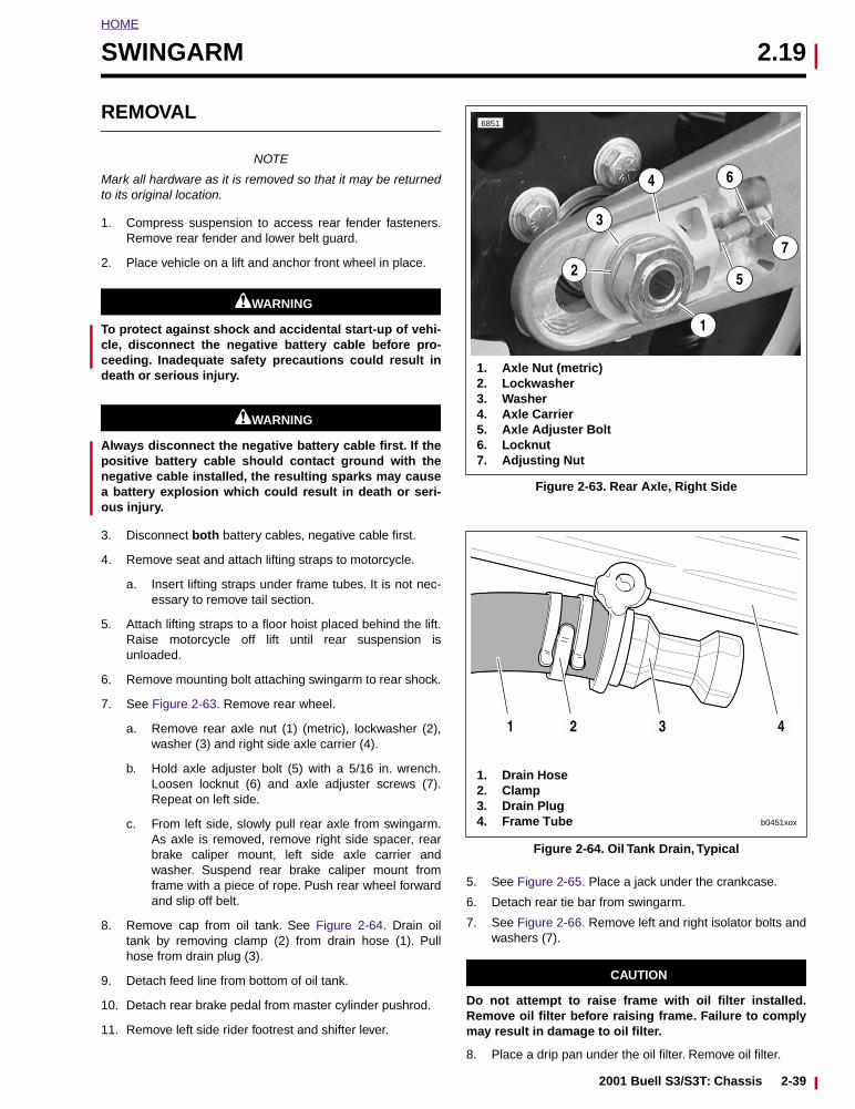
HOME
SWINGARM 2.19
REMOVAL
NOTE
Mark all hardware as it is removed so that it may be returnedto its original location.
1. Compress suspension to access rear fender fasteners.Remove rear fender and lower belt guard.
2. Place vehicle on a lift and anchor front wheel in place.
11WARNING1WARNING
To protect against shock and accidental start-up of vehi-cle, disconnect the negative battery cable before pro-ceeding. Inadequate safety precautions could result indeath or serious injury.
11WARNING1WARNING
Always disconnect the negative battery cable first. If thepositive battery cable should contact ground with thenegative cable installed, the resulting sparks may causea battery explosion which could result in death or seri-ous injury.
3. Disconnect both battery cables, negative cable first.
4. Remove seat and attach lifting straps to motorcycle.
a. Insert lifting straps under frame tubes. It is not nec-essary to remove tail section.
5. Attach lifting straps to a floor hoist placed behind the lift.Raise motorcycle off lift until rear suspension isunloaded.
6. Remove mounting bolt attaching swingarm to rear shock.
7. See Figure 2-63. Remove rear wheel.
a. Remove rear axle nut (1) (metric), lockwasher (2),washer (3) and right side axle carrier (4).
b. Hold axle adjuster bolt (5) with a 5/16 in. wrench.Loosen locknut (6) and axle adjuster screws (7).Repeat on left side.
c. From left side, slowly pull rear axle from swingarm.As axle is removed, remove right side spacer, rearbrake caliper mount, left side axle carrier andwasher. Suspend rear brake caliper mount fromframe with a piece of rope. Push rear wheel forwardand slip off belt.
8. Remove cap from oil tank. See Figure 2-64. Drain oiltank by removing clamp (2) from drain hose (1). Pullhose from drain plug (3).
9. Detach feed line from bottom of oil tank.
10. Detach rear brake pedal from master cylinder pushrod.
11. Remove left side rider footrest and shifter lever.
5. See Figure 2-65. Place a jack under the crankcase.
6. Detach rear tie bar from swingarm.
7. See Figure 2-66. Remove left and right isolator bolts andwashers (7).
CAUTION
Do not attempt to raise frame with oil filter installed.Remove oil filter before raising frame. Failure to complymay result in damage to oil filter.
8. Place a drip pan under the oil filter. Remove oil filter.
Figure 2-63. Rear Axle, Right Side
Figure 2-64. Oil Tank Drain, Typical
6851
5
4
3
6
7
1
2
1. Axle Nut (metric)2. Lockwasher3. Washer4. Axle Carrier5. Axle Adjuster Bolt6. Locknut7. Adjusting Nut
1. Drain Hose2. Clamp3. Drain Plug4. Frame Tube
1 2 3 4
b0451xox
2001 Buell S3/S3T: Chassis 2-39
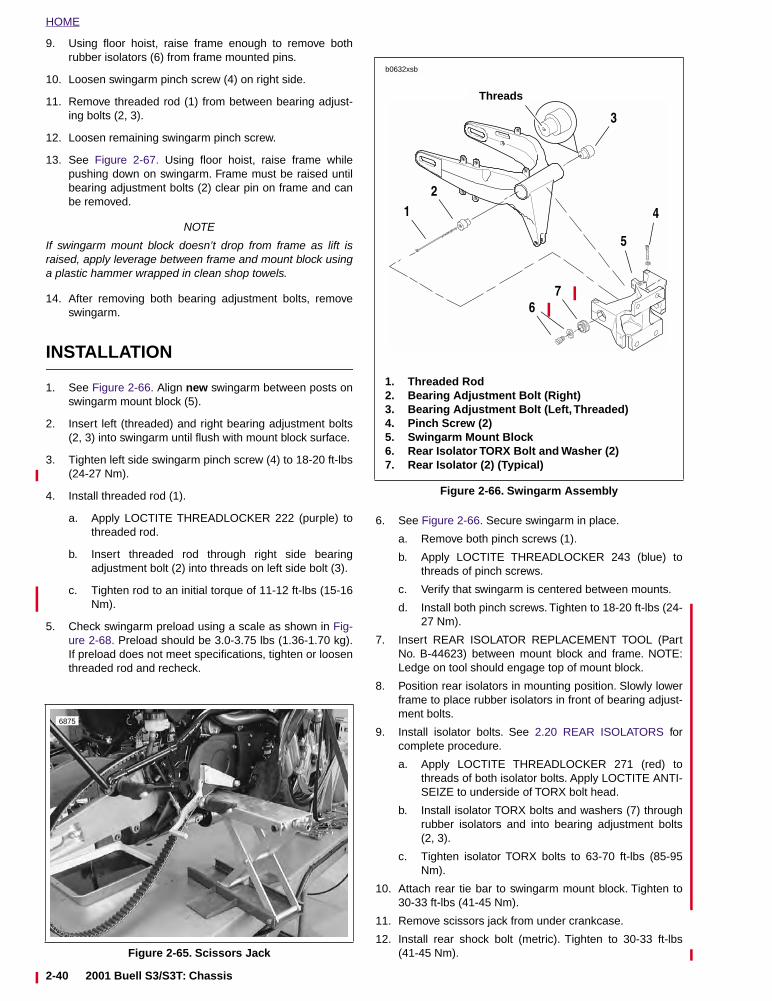
HOME
9. Using floor hoist, raise frame enough to remove bothrubber isolators (6) from frame mounted pins.
10. Loosen swingarm pinch screw (4) on right side.
11. Remove threaded rod (1) from between bearing adjust-ing bolts (2, 3).
12. Loosen remaining swingarm pinch screw.
13. See Figure 2-67. Using floor hoist, raise frame whilepushing down on swingarm. Frame must be raised untilbearing adjustment bolts (2) clear pin on frame and canbe removed.
NOTE
If swingarm mount block doesn’t drop from frame as lift israised, apply leverage between frame and mount block usinga plastic hammer wrapped in clean shop towels.
14. After removing both bearing adjustment bolts, removeswingarm.
INSTALLATION
1. See Figure 2-66. Align new swingarm between posts onswingarm mount block (5).
2. Insert left (threaded) and right bearing adjustment bolts(2, 3) into swingarm until flush with mount block surface.
3. Tighten left side swingarm pinch screw (4) to 18-20 ft-lbs(24-27 Nm).
4. Install threaded rod (1).
a. Apply LOCTITE THREADLOCKER 222 (purple) tothreaded rod.
b. Insert threaded rod through right side bearingadjustment bolt (2) into threads on left side bolt (3).
c. Tighten rod to an initial torque of 11-12 ft-lbs (15-16Nm).
5. Check swingarm preload using a scale as shown in Fig-ure 2-68. Preload should be 3.0-3.75 lbs (1.36-1.70 kg).If preload does not meet specifications, tighten or loosenthreaded rod and recheck.
6. See Figure 2-66. Secure swingarm in place.
a. Remove both pinch screws (1).
b. Apply LOCTITE THREADLOCKER 243 (blue) tothreads of pinch screws.
c. Verify that swingarm is centered between mounts.
d. Install both pinch screws. Tighten to 18-20 ft-lbs (24-27 Nm).
7. Insert REAR ISOLATOR REPLACEMENT TOOL (PartNo. B-44623) between mount block and frame. NOTE:Ledge on tool should engage top of mount block.
8. Position rear isolators in mounting position. Slowly lowerframe to place rubber isolators in front of bearing adjust-ment bolts.
9. Install isolator bolts. See 2.20 REAR ISOLATORS forcomplete procedure.
a. Apply LOCTITE THREADLOCKER 271 (red) tothreads of both isolator bolts. Apply LOCTITE ANTI-SEIZE to underside of TORX bolt head.
b. Install isolator TORX bolts and washers (7) throughrubber isolators and into bearing adjustment bolts(2, 3).
c. Tighten isolator TORX bolts to 63-70 ft-lbs (85-95Nm).
10. Attach rear tie bar to swingarm mount block. Tighten to30-33 ft-lbs (41-45 Nm).
11. Remove scissors jack from under crankcase.
12. Install rear shock bolt (metric). Tighten to 30-33 ft-lbs(41-45 Nm).Figure 2-65. Scissors Jack
6875
Figure 2-66. Swingarm Assembly
1. Threaded Rod2. Bearing Adjustment Bolt (Right)3. Bearing Adjustment Bolt (Left, Threaded)4. Pinch Screw (2)5. Swingarm Mount Block6. Rear Isolator TORX Bolt and Washer (2)7. Rear Isolator (2) (Typical)
Threads
b0632xsb
1
7
4
3
2
5
6
2-40 2001 Buell S3/S3T: Chassis
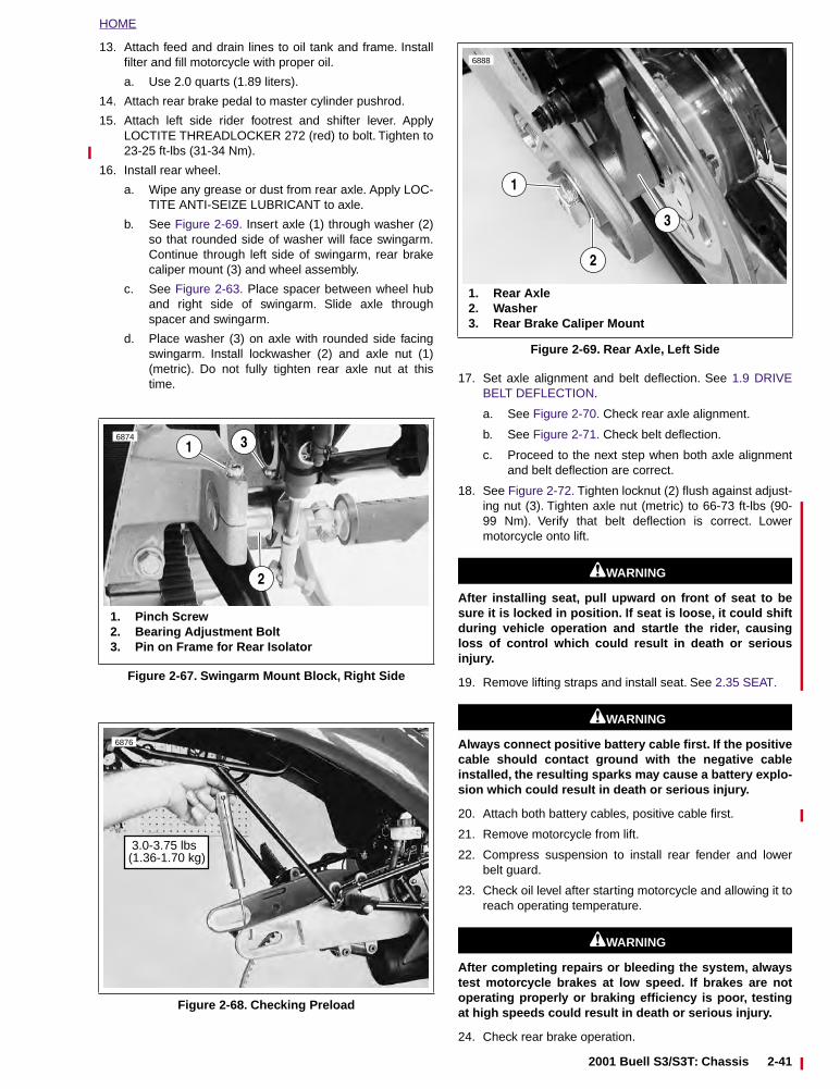
HOME
13. Attach feed and drain lines to oil tank and frame. Installfilter and fill motorcycle with proper oil.
a. Use 2.0 quarts (1.89 liters).
14. Attach rear brake pedal to master cylinder pushrod.
15. Attach left side rider footrest and shifter lever. ApplyLOCTITE THREADLOCKER 272 (red) to bolt. Tighten to23-25 ft-lbs (31-34 Nm).
16. Install rear wheel.
a. Wipe any grease or dust from rear axle. Apply LOC-TITE ANTI-SEIZE LUBRICANT to axle.
b. See Figure 2-69. Insert axle (1) through washer (2)so that rounded side of washer will face swingarm.Continue through left side of swingarm, rear brakecaliper mount (3) and wheel assembly.
c. See Figure 2-63. Place spacer between wheel huband right side of swingarm. Slide axle throughspacer and swingarm.
d. Place washer (3) on axle with rounded side facingswingarm. Install lockwasher (2) and axle nut (1)(metric). Do not fully tighten rear axle nut at thistime. 17. Set axle alignment and belt deflection. See 1.9 DRIVE
BELT DEFLECTION.
a. See Figure 2-70. Check rear axle alignment.
b. See Figure 2-71. Check belt deflection.
c. Proceed to the next step when both axle alignmentand belt deflection are correct.
18. See Figure 2-72. Tighten locknut (2) flush against adjust-ing nut (3). Tighten axle nut (metric) to 66-73 ft-lbs (90-99 Nm). Verify that belt deflection is correct. Lowermotorcycle onto lift.
11WARNING1WARNING
After installing seat, pull upward on front of seat to besure it is locked in position. If seat is loose, it could shiftduring vehicle operation and startle the rider, causingloss of control which could result in death or seriousinjury.
19. Remove lifting straps and install seat. See 2.35 SEAT.
11WARNING1WARNING
Always connect positive battery cable first. If the positivecable should contact ground with the negative cableinstalled, the resulting sparks may cause a battery explo-sion which could result in death or serious injury.
20. Attach both battery cables, positive cable first.
21. Remove motorcycle from lift.
22. Compress suspension to install rear fender and lowerbelt guard.
23. Check oil level after starting motorcycle and allowing it toreach operating temperature.
11WARNING1WARNING
After completing repairs or bleeding the system, alwaystest motorcycle brakes at low speed. If brakes are notoperating properly or braking efficiency is poor, testingat high speeds could result in death or serious injury.
24. Check rear brake operation.
Figure 2-67. Swingarm Mount Block, Right Side
Figure 2-68. Checking Preload
1. Pinch Screw2. Bearing Adjustment Bolt3. Pin on Frame for Rear Isolator
6874
1
2
3
6876
3.0-3.75 lbs (1.36-1.70 kg)
Figure 2-69. Rear Axle, Left Side
6888
1
2
3
1. Rear Axle2. Washer3. Rear Brake Caliper Mount
2001 Buell S3/S3T: Chassis 2-41
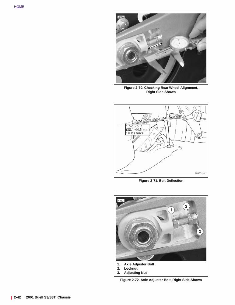
HOME
.
Figure 2-70. Checking Rear Wheel Alignment,Right Side Shown
Figure 2-71. Belt Deflection
Figure 2-72. Axle Adjuster Bolt, Right Side Shown
6816
b0633xsb
1.5-1.75 in.(38.1-44.5 mm)10 lbs force
6852
12
1. Axle Adjuster Bolt2. Locknut3. Adjusting Nut
3
2-42 2001 Buell S3/S3T: Chassis
HOME
REAR ISOLATORS 2.20
MODEL YEAR CHANGE
All 2001 Air Twin Buell Models have new isolators with snub-bers to reduce isolator shear. The sprocket cover has beenmodified from previous years to allow clearance for the snub-ber.
REMOVAL
11WARNING1WARNING
To protect against shock and accidental start-up of vehi-cle, disconnect the negative battery cable before pro-ceeding. Inadequate safety precautions could result indeath or serious injury.
11WARNING1WARNING
Always disconnect the negative battery cable first. If thepositive battery cable should contact ground with thenegative cable installed, the resulting sparks may causea battery explosion which could result in death or seri-ous injury.
1. Disconnect both battery cables from battery, negativecable first.
2. Remove seat and fuel tank. See 2.35 SEAT and 4.36FUEL TANK.
3. Remove the left side rider footpeg mounting bolt andfootpeg. Allow footpeg and shift linkage to hang beingcareful not to scratch primary cover.
4. See Figure 2-73. On the right side of the motorcycle,remove the front sprocket cover assembly.
5. See Figure 2-73. Remove two screws that attachsprocket cover to the backside of the swingarm/drivesupport. Retain screws. Discard sprocket cover.
NOTESee Figure 2-74. Route strap under frame rails with tail sec-tion installed. Make sure strap is in “V” formed by frame railsto prevent rearward movement and that it does not pinch wir-ing harness, vent lines or cables.
6. See Figure 2-74. Strap tail section of frame to overheadbeam or hoist and put slight tension on strap to secureframe assembly.
7. See Figure 2-75. Remove frame side tie bar mountinghardware from front lower and center tie bars. Leavefourth tie bar (front upper) attached to both frame andengine.
8. See Figure 2-75. Remove rear tie bar bolt, lockwasherand washers from mount block. Discard lockwasher.
9. See Figure 2-75. Loosen left side isolator bolt from swingarm bearing adjusting bolt. Do not remove.
10. See Figure 2-75. Remove right side isolator bolt andwasher from swingarm bearing adjustment bolt. Discardisolator bolt, but retain washer.
Figure 2-73. Sprocket Cover
b0204x2a
20-25 ft-lbs(27-34 Nm)
Screws (2)
Locknut30-35 ft-lbs(41-47 Nm)
Swingarm/DriveSupport
Red Loctite
Screw48-72 in-lbs(5-9 Nm)Blue Loctite
Screws (2)Blue Loctite
Spacer
Sprocket Cover
2001 Buell S3/S3T: Chassis 2-43
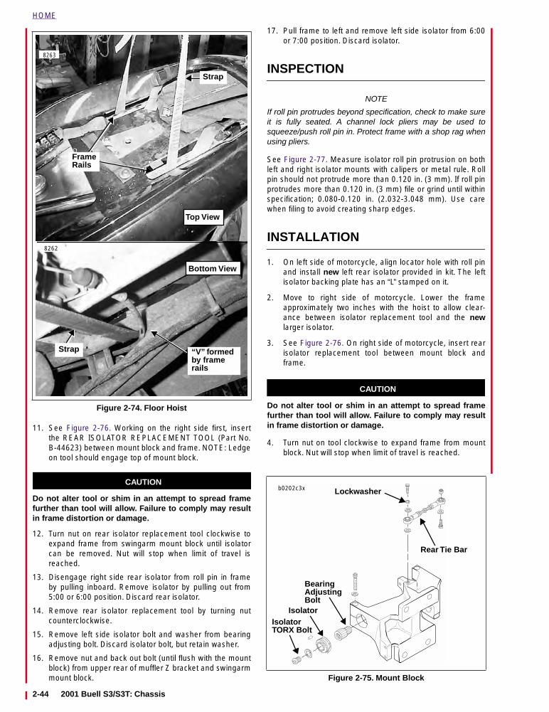
HOME
11. See Figure 2-76. Working on the right side first, insertthe REAR ISOLATOR REPLACEMENT TOOL (Part No.B-44623) between mount block and frame. NOTE: Ledgeon tool should engage top of mount block.
CAUTION
Do not alter tool or shim in an attempt to spread framefurther than tool will allow. Failure to comply may resultin frame distortion or damage.
12. Turn nut on rear isolator replacement tool clockwise toexpand frame from swingarm mount block until isolatorcan be removed. Nut will stop when limit of travel isreached.
13. Disengage right side rear isolator from roll pin in frameby pulling inboard. Remove isolator by pulling out from5:00 or 6:00 position. Discard rear isolator.
14. Remove rear isolator replacement tool by turning nutcounterclockwise.
15. Remove left side isolator bolt and washer from bearingadjusting bolt. Discard isolator bolt, but retain washer.
16. Remove nut and back out bolt (until flush with the mountblock) from upper rear of muffler Z bracket and swingarmmount block.
17. Pull frame to left and remove left side isolator from 6:00or 7:00 position. Discard isolator.
INSPECTION
NOTE
If roll pin protrudes beyond specification, check to make sureit is fully seated. A channel lock pliers may be used tosqueeze/push roll pin in. Protect frame with a shop rag whenusing pliers.
See Figure 2-77. Measure isolator roll pin protrusion on bothleft and right isolator mounts with calipers or metal rule. Rollpin should not protrude more than 0.120 in. (3 mm). If roll pinprotrudes more than 0.120 in. (3 mm) file or grind until withinspecification; 0.080-0.120 in. (2.032-3.048 mm). Use carewhen filing to avoid creating sharp edges.
INSTALLATION
1. On left side of motorcycle, align locator hole with roll pinand install new left rear isolator provided in kit. The leftisolator backing plate has an “L” stamped on it.
2. Move to right side of motorcycle. Lower the frameapproximately two inches with the hoist to allow clear-ance between isolator replacement tool and the newlarger isolator.
3. See Figure 2-76. On right side of motorcycle, insert rearisolator replacement tool between mount block andframe.
CAUTION
Do not alter tool or shim in an attempt to spread framefurther than tool will allow. Failure to comply may resultin frame distortion or damage.
4. Turn nut on tool clockwise to expand frame from mountblock. Nut will stop when limit of travel is reached.
Figure 2-74. Floor Hoist
8263
8262
FrameRails
Strap
“V” formed by frame rails
Strap
Top View
Bottom View
Figure 2-75. Mount Block
b0202c3x
Rear Tie Bar
IsolatorTORX Bolt
Lockwasher
Isolator
BearingAdjustingBolt
2-44 2001 Buell S3/S3T: Chassis
HOME
5. On right side of motorcycle, align locator hole with rollpin and install new right rear isolator provided in kit. Theright isolator backing plate has an “R” stamped on it.
6. Turn nut on tool counterclockwise to allow frame toreturn to position. Remove tool from between frame andmount block.
7. Raise frame with hoist to align isolator bolt holes withthreaded holes in bearing adjusting bolts.
8. Mark a horizontal line across the front of each isolatorwith a light colored grease pencil or by other non-perma-nent means.
9. Apply anti-seize to underside of new isolator bolt heads.
CAUTION
Use caution when installing isolator bolts. Make sure iso-lator bolt hole is aligned with threaded hole in bearingadjusting bolt to avoid cross-threading bolt.
10. See Figure 2-75. Install new isolator TORX bolts andwashers through both rubber isolators into bearingadjustment bolts on each side.
CAUTION
See Figure 2-78. Observe marked line on both rubber iso-lators after isolator bolts are tightened. If line twists,apply more LOCTITE ANTI-SEIZE to underside of isolatorbolt heads. Failure to comply will result in damage torubber isolators.
11. Tighten right and left isolator bolts to 63-70 ft-lbs (85-95Nm).
12. Push rear upper Z bracket bolt until it protrudes frommount block and install nut. Tighten rear upper Z-bracketbolt to 22-24 ft-lbs (30-33 Nm).
13. Erase grease pencil marked lines from both isolators.
14. Install front lower and center tie bars to frame with origi-nal locknuts. Tighten bolts to 30-33 ft-lbs (41-45 Nm).Install rear tie bar to mount block with new lockwasher.Tighten bolt to 30-33 ft-lbs. (41-45 Nm).
15. Remove hoist from tail section.
16. Install left side rider footpeg. Tighten bolt to 25-30 ft-lbs(34-41 Nm).
17. See Figure 2-73. Apply LOCTITE THREADLOCKER 243(Blue) to threads of two sprocket cover to swingarm/drivesupport screws and install new sprocket cover to swing-arm/drive support.
18. See Figure 2-73. Install new sprocket cover assemblywith original hardware.
a. Apply LOCTITE THREADLOCKER 243 (blue) toscrew. Install sprocket cover assembly with screw,washer and spacer. Tighten to 48-72 in-lbs (5-9Nm).
b. Apply LOCTITE THREADLOCKER 272 (red) toswingarm/drive support mounting screws andinstall. Tighten screws to 20-25 ft-lbs (27-34 Nm).
c. Install locknut and washer. Tighten to 30-35 ft-lbs(41-47 Nm).
Figure 2-76. Rear Isolator Replacement Tool In Use
Figure 2-77. Measuring Roll Pin Protrusion
b0869x2x
Ledge
Mount Block
Frame
ReplacementTool (B-44623)
RearIsolator
0.080-0.120 in. (2.032-3.048 mm)
Pin
Figure 2-78. Isolator Alignment
b0674b2x
Straight Line(Correct)
Twisted Line(Incorrect)
Marked
Rear Isolator
Line
OBSERVE MARKED LINE WHILE TIGHTENING
2001 Buell S3/S3T: Chassis 2-45
HOME
11WARNING1WARNING
After installing seat, pull upward on front of seat to besure it is locked in position. If seat is loose, it could shiftduring vehicle operation and startle the rider, causingloss of control which could result in death or seriousinjury.
19. Install fuel tank and seat. See 2.35 SEAT and 4.36 FUELTANK.
11WARNING1WARNING
Always connect the positive battery cable first. If thepositive cable should contact ground with the negativecable installed, the resulting sparks may cause a batteryexplosion, which could result in death or serious injury.
20. Connect battery cables, positive cable first, to battery ter-minals.
21. Test ride motorcycle at low speed and check for properoperation.
2-46 2001 Buell S3/S3T: Chassis
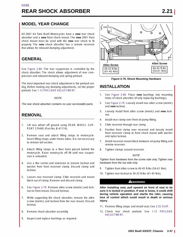
HOME
REAR SHOCK ABSORBER 2.21
MODEL YEAR CHANGE
All 2001 Air Twin Buell Motorcycles have a new rear shockabsorber and a new front shock mount. The new 2001 frontshock mount must be used with the new rear shock to fitproperly. The new shock absorber has a remote reservoirthat allows for rebound damping adjustment.
GENERAL
See Figure 2-80. The rear suspension is controlled by theshock absorber. The shock allows adjustment of rear com-pression and rebound damping and spring preload.
The most important rear shock adjustment is the preload set-ting. Before making any damping adjustments, set the properpreload. See 1.12 PRELOAD ADJUSTMENT.
NOTE
The rear shock absorber contains no user serviceable parts.
REMOVAL
1. Lift rear wheel off ground using REAR WHEEL SUP-PORT STAND (Part No. B-41174).
2. Remove seat and attach lifting straps to motorcycle.Insert lifting straps under frame tubes. It is not necessaryto remove tail section.
3. Attach lifting straps to a floor hoist placed behind themotorcycle. Raise motorcycle off lift until rear suspen-sion is unloaded.
4. Use a flex socket and extension to remove locknut andwasher from front reservoir clamp. Discard clamp andlocknut.
5. Loosen rear reservoir clamp. Slide reservoir and mountblock out of clamp. Remove and discard clamp.
6. See Figure 2-79. Remove allen screw (metric) and lock-nut on front mount. Discard locknut.
7. While supporting the shock absorber, remove the allenscrew (metric) and locknut from the rear mount. Discardlocknut.
8. Remove shock absorber assembly.
9. Inspect and replace bushings as required.
INSTALLATION
1. See Figure 2-80. Place new bushings into mountingholes of shock absorber (if only replacing bushings).
2. See Figure 2-79. Loosely install rear allen screw (metric)and new locknut.
3. Loosely install front allen screw (metric) and new lock-nut.
4. Install rear clamp over front oil pump fitting.
5. Slide reservoir through rear clamp.
6. Position front clamp over reservoir and loosely installfront reservoir clamp to front shock mount with washerand nylon locknut.
7. Install reservoir mount block between oil pump fitting andremote reservoir.
8. Tighten clamps around reservoir.
NOTE
Tighten front hardware from the screw side only. Tighten rearhardware from the nut side only.
9. Tighten front allen screw to 40-45 ft-lbs (54-61 Nm).
10. Tighten rear locknut to 30-33 ft-lbs (41-45 Nm).
11WARNING1WARNING
After installing seat, pull upward on front of seat to besure it is locked in position. If seat is loose, it could shiftduring vehicle operation and startle the rider, causingloss of control which could result in death or seriousinjury.
11. Remove lifting straps and install seat. See 2.35 SEAT.
12. Check rear shock preload. See 1.12 PRELOADADJUSTMENT.
Figure 2-79. Shock Mounting Hardware
b0855x2x
Allen ScrewAllen Screw40-45 ft-lbs(54-61 Nm)
30-33 ft-lbs(41-45 Nm)
2001 Buell S3/S3T: Chassis 2-47
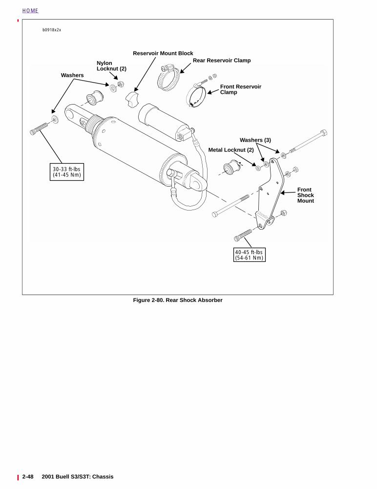
HOME
Figure 2-80. Rear Shock Absorber
b0918x2x
Rear Reservoir Clamp
Front ReservoirClamp
Nylon
40-45 ft-lbs(54-61 Nm)
FrontShockMount
Reservoir Mount Block
Metal Locknut (2)
30-33 ft-lbs(41-45 Nm)
Washers (3)
Locknut (2)Washers
2-48 2001 Buell S3/S3T: Chassis
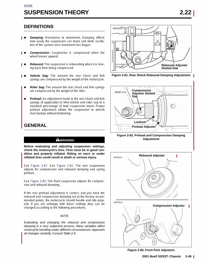
HOME
SUSPENSION THEORY 2.22
DEFINITIONS
● Damping: Resistance to movement. Damping affectshow easily the suspension can move and limits oscilla-tion of the system once movement has begun.
● Compression: Suspension is compressed when thewheel moves upward.
● Rebound: The suspension is rebounding when it is mov-ing back from being compressed.
● Vehicle Sag: The amount the rear shock and forksprings are compressed by the weight of the motorcycle.
● Rider Sag: The amount the rear shock and fork springsare compressed by the weight of the rider.
● Preload: An adjustment made to the rear shock and forksprings (if applicable) to limit vehicle and rider sag to astandard percentage of total suspension travel. Properpreload adjustment allows the suspension to absorbmost bumps without bottoming.
GENERAL
11WARNING1WARNING
Before evaluating and adjusting suspension settings,check the motorcycle’s tires. Tires must be in good con-dition and properly inflated. Riding on worn or underinflated tires could result in death or serious injury.
See Figure 2-81. See Figure 2-82. The rear suspensionadjusts for compression and rebound damping and springpreload.
See Figure 2-83. The front suspension adjusts for compres-sion and rebound damping.
If the rear preload adjustment is correct, and you have therebound and compression damping set at the factory recom-mended points, the motorcycle should handle and ride prop-erly. If you are unhappy with these settings they can bechanged according to the following procedures.
NOTE
Evaluating and changing the rebound and compressiondamping is a very subjective process. Many variables affectmotorcycle handling under different circumstances. Approachall changes carefully. Consult Table 2-9.
Figure 2-81. Rear Shock Rebound Damping Adjustment
Figure 2-82. Preload and Compression Damping Adjustment
Figure 2-83. Front Fork Adjusters
b0854x2x
Rebound AdjusterSlotted Dial
Locknut
Dial
CompressionAdjuster Slotted
Preload Adjuster
b00851x2x
b0559xox
b0558xox
Rebound Adjuster
Compression Adjuster
2001 Buell S3/S3T: Chassis 2-49
HOME
SUSPENSION ADJUSTMENTS 2.23
SPRING PRELOAD
Adjust rear spring preload before attempting any other adjust-ments. See 1.12 PRELOAD ADJUSTMENT. This settingassures that the rear suspension has the proper amount oftravel for the rider’s weight and the motorcycle’s cargo load.
Make this adjustment before the motorcycle is ridden any dis-tance. Your Buell dealer can assist you if necessary.
ADJUSTMENTS
Evaluating and changing the rebound and compressiondamping is a very subjective process. A good performing sus-pension finds a proper balance between spring, spring pre-load, damping, track conditions and riding speed. However,all settings are at best a compromise. If a rider fails to find agood set-up, go back to the factory recommended settingsand start over again.
Make all suspension adjustments in one or two click incre-ments. Adjusting more than one or two clicks at a time maycause you to skip the best adjustment. Test ride after eachadjustment. When an adjustment makes no difference, returnto the previous adjustment and try a different approach.
To find the optimum settings you will need the preload prop-erly adjusted, the tires properly inflated and a familiar bumpyroad. It is useful if the road contains a variety of differentbumps from small sharp bumps such as potholes or frostheaves to large undulations. Begin the process by putting allthe damping adjustments at the factory recommended set-tings. Ride the bike over a variety of different surfaces andbumps at different speeds. When the suspension is set prop-erly the motorcycle will be stable and comfortable.
REAR SHOCK DAMPING ADJUSTMENTS
Beyond the rear preload adjustment, the rear shock can alsobe adjusted for compression and rebound damping. However,it is important to note the rear preload must be set correctlybefore performing any other adjustments.
See Figure 2-81. Adjust rebound damping using the slotteddial on the remote reservoir at the front of the shock.
● Factory setting-full damping minus 1 turn.
See Figure 2-82. Adjust compression damping using theslotted dial on the shaft at the end of the shock.
● Factory setting-full damping minus 2.5 turns.
Adjusting Rear Shock
1. Using a screwdriver, turn the slotted dial on the appropri-ate adjuster clockwise until it stops. This is the maximumdamping setting for that adjustment.
2. Then turn the dial counterclockwise the recommendedamount to align the reference marks. This is the factoryrecommended setting.
Recommended Rear Shock Damping Settings (S3/S3T)
FRONT FORK DAMPINGADJUSTMENTS
See Figure 2-83. Adjust rebound damping using the slotteddial on the top of each fork leg.
● Factory setting-full damping minus 0.5 turn.
See Figure 2-83. Adjust compression damping using theslotted dial on the bottom of each fork leg.
● Factory setting-full damping minus 1.75 turns.
Adjusting Front Forks
11WARNING1WARNING
Always adjust each fork leg to the same settings. Unevenadjustment between left and right forks may lead to aloss of control which could result in death or seriousinjury.
1. Using a screwdriver, turn the slotted dial on the appropri-ate adjuster clockwise until it stops. This is the maximumdamping setting for that adjustment.
2. Then turn the dial counterclockwise the recommendedamount to align the reference marks. This is the factoryrecommended setting.
TROUBLESHOOTING
11WARNING1WARNING
This section is intended solely as a guide to diagnosingproblems. Carefully read the appropriate sections of thismanual before performing any work. Improper suspen-sion adjustments may cause loss of control which couldresult in death or serious injury.
The following tables list possible suspension and operatingtroubles and their probable causes. Use the tables to keepyour motorcycle in good operating condition.
When making adjustments, remember there are two medi-ums in setting up a bike, geometry and suspension. Bothcomponents work together because suspension is a part ofgeometry. In order to solve handling problems, it is importantto diagnose the problem’s true nature. Chattering, sliding or
SETTINGSSOLO(STD)
2 UPSOLO(FIRM)
SOLO(SOFT)
Front Rebound 0.5 1 0.5 1.5
Front Compression
1.75 1.25 1.25 MIN
Rear Rebound 1 0.5 0.5 2.5
Rear Compression
2.5 0.25 1 MIN
2-50 2001 Buell S3/S3T: Chassis
HOME
an uncomfortable feeling are suspension problems. Handlingand a swinging fork are geometry-related, but often theseunwanted characteristics can be solved by suspension
adjustments.
Table 2-6. General Suspension Problems
TROUBLESHOOTING CONDITION ADJUSTMENT SOLUTION
Bike wallows through turns.Feels loose or vague after bumps.Wheel tends to “pogo” after passing over a bump. This is notice-able by watching the bike continue to bounce as it travels over mul-tiple bumps.
Increase rebound damping.
Wheel responds to bump, but doesn’t return to ground quickly after bumps. This is more pronounced over a series of bumps and is often referred to as “packing down.”
Reduce rebound damping.
The bike bottoms out or dips while cornering.Bike has excessive brake dive.
Increase compression damping.
Harsh ride particularly over washboard surfaces.Bumps kick through handlebars or seat.Suspension seems not to respond to bumps. This is evidenced by tire chattering (a movement with short stroke and high frequency) through corners or by jolting the rider over rough roads.
Reduce compression damping.
Table 2-7. Rear Suspension Problems
TROUBLESHOOTING CONDITION ADJUSTMENT SOLUTION
“Pumping on the Rear” occurs when you are accelerating out of a corner. This problems occurs in two varieties.1. The first type has a movement with a long stroke and a high
frequency.
2. The second version has a movement with a short stroke andhigh frequency.
1. The shock is too soft. Increase compressiondamping. If the adjuster is already set to the max-imum, add more preload to the spring (one turnmaximum).
2. In this case the shock is too hard. Decrease com-pression damping.
Chattering during braking. Decrease the compression damping. If the problem persists, decrease rebound damping for a faster rebound rate. Less spring preload may also help.
Lack of tire feedback. The suspension is too soft. Increase compression damping.
Sliding during cornering. Sliding may occur going into the corner or accelerating out of the corner.
The suspension is too hard. Decrease compression damping.
Table 2-8. Front Suspension Problems
TROUBLESHOOTING CONDITION ADJUSTMENT SOLUTION
Not absorbing bumps. A good suspension is a balance between damping and track condition. Finding this balance requires exploring all possible compression settings.
Lack of tire feedback. Increase compression damping.
Tire slides. Decrease compression damping.
2001 Buell S3/S3T: Chassis 2-51

HOME
Table 2-9. Rider Suspension Preferences NOTE
All adjustments require rear shock preload to be properly adjusted for the rider’s size and weight. For information on setting rearshock preload, see 1.12 PRELOAD ADJUSTMENT.
DATEFRONT FORK
REBOUNDFRONT FORK
COMPRESSIONREAR SHOCK
REBOUNDREAR SHOCK
COMPRESSIONRESULTS
Max damping minus 0.5 turn
Max damping minus 1.75 turns
Max damping minus 1 turn
Max damping minus 2.5 turns
Factory recommended settings.
2-52 2001 Buell S3/S3T: Chassis
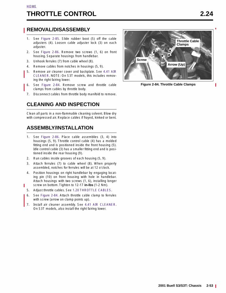
HOME
THROTTLE CONTROL 2.24
REMOVAL/DISASSEMBLY
1. See Figure 2-85. Slide rubber boot (5) off the cableadjusters (4). Loosen cable adjuster lock (3) on eachadjuster.
2. See Figure 2-86. Remove two screws (1, 6) on fronthousing. Separate housings from handlebar.
3. Unhook ferrules (7) from cable wheel (8).
4. Remove cables from notches in housings (5, 9).
5. Remove air cleaner cover and backplate. See 4.41 AIRCLEANER. NOTE: On S3T models, this includes remov-ing the right fairing lower.
6. See Figure 2-84. Remove screw and throttle cableclamps from cables by throttle body.
7. Disconnect cables from throttle body manifold to remove.
CLEANING AND INSPECTION
Clean all parts in a non-flammable cleaning solvent. Blow drywith compressed air. Replace cables if frayed, kinked or bent.
ASSEMBLY/INSTALLATION
1. See Figure 2-86. Place cable assemblies (3, 4) intohousings (5, 9). Throttle control cable (4) has a moldedfitting end and is positioned inside the front housing (5).Idle control cable (3) has a smaller fitting end and is posi-tioned inside the rear housing (9).
2. Run cables inside grooves of each housing (5, 9).
3. Attach ferrules (7) to cable wheel (8). When properlyassembled, notches for ferrules will be at 12 o’clock.
4. Position housings on right handlebar by engaging locat-ing pin (10) on front housing with hole in handlebar.Attach housings with two screws (1, 6), installing longerscrew on bottom. Tighten to 12-17 in-lbs (1-2 Nm).
5. Adjust throttle cables. See 1.20 THROTTLE CABLES.
6. See Figure 2-84. Attach throttle cable clamp to ferruleswith screw (arrow on clamp points up).
7. Install air cleaner assembly. See 4.41 AIR CLEANER.On S3T models, also install the right fairing lower.
Figure 2-84. Throttle Cable Clamps
Throttle CableClamps
Arrow (Up)Screw
2001 Buell S3/S3T: Chassis 2-53
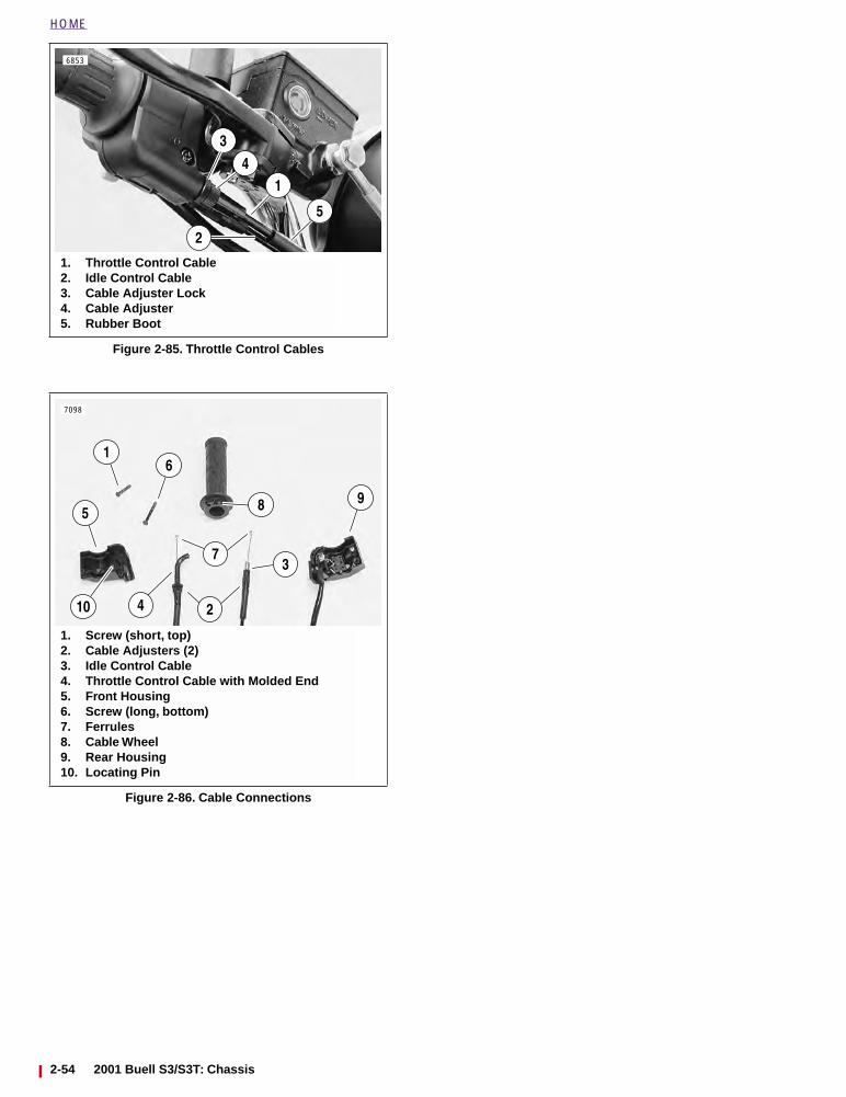
HOME
Figure 2-85. Throttle Control Cables
Figure 2-86. Cable Connections
1. Throttle Control Cable2. Idle Control Cable3. Cable Adjuster Lock4. Cable Adjuster5. Rubber Boot
1
3
2
4
6853
5
1. Screw (short, top)2. Cable Adjusters (2)3. Idle Control Cable4. Throttle Control Cable with Molded End5. Front Housing6. Screw (long, bottom)7. Ferrules8. Cable Wheel9. Rear Housing10. Locating Pin
1
7098
598
6
24
37
10
2-54 2001 Buell S3/S3T: Chassis
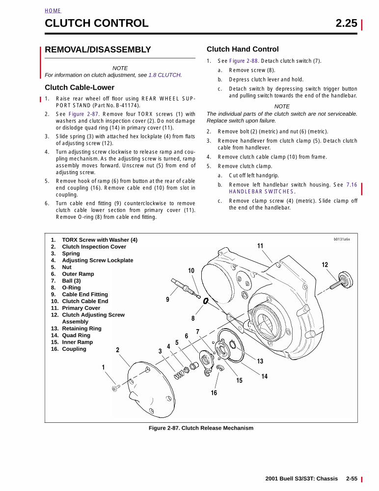
HOME
CLUTCH CONTROL 2.25
REMOVAL/DISASSEMBLY
NOTEFor information on clutch adjustment, see 1.8 CLUTCH.
Clutch Cable-Lower1. Raise rear wheel off floor using REAR WHEEL SUP-
PORT STAND (Part No. B-41174).
2. See Figure 2-87. Remove four TORX screws (1) withwashers and clutch inspection cover (2). Do not damageor dislodge quad ring (14) in primary cover (11).
3. Slide spring (3) with attached hex lockplate (4) from flatsof adjusting screw (12).
4. Turn adjusting screw clockwise to release ramp and cou-pling mechanism. As the adjusting screw is turned, rampassembly moves forward. Unscrew nut (5) from end ofadjusting screw.
5. Remove hook of ramp (6) from button at the rear of cableend coupling (16). Remove cable end (10) from slot incoupling.
6. Turn cable end fitting (9) counterclockwise to removeclutch cable lower section from primary cover (11).Remove O-ring (8) from cable end fitting.
Clutch Hand Control
1. See Figure 2-88. Detach clutch switch (7).
a. Remove screw (8).
b. Depress clutch lever and hold.
c. Detach switch by depressing switch trigger buttonand pulling switch towards the end of the handlebar.
NOTEThe individual parts of the clutch switch are not serviceable.Replace switch upon failure.
2. Remove bolt (2) (metric) and nut (6) (metric).
3. Remove handlever from clutch clamp (5). Detach clutchcable from handlever.
4. Remove clutch cable clamp (10) from frame.
5. Remove clutch clamp.
a. Cut off left handgrip.
b. Remove left handlebar switch housing. See 7.16HANDLEBAR SWITCHES.
c. Remove clamp screw (4) (metric). Slide clamp offthe end of the handlebar.
Figure 2-87. Clutch Release Mechanism
1. TORX Screw with Washer (4)2. Clutch Inspection Cover3. Spring 4. Adjusting Screw Lockplate5. Nut6. Outer Ramp7. Ball (3)8. O-Ring9. Cable End Fitting10. Clutch Cable End11. Primary Cover12. Clutch Adjusting Screw
Assembly13. Retaining Ring14. Quad Ring15. Inner Ramp16. Coupling
b0131a6x
1
2 34 5
67
16
15
8
9
10
11
12
13
14
2001 Buell S3/S3T: Chassis 2-55
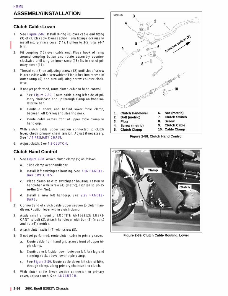
HOME
ASSEMBLY/INSTALLATION
Clutch Cable-Lower
1. See Figure 2-87. Install O-ring (8) over cable end fitting(9) of clutch cable lower section. Turn fitting clockwise toinstall into primary cover (11). Tighten to 3-5 ft-lbs (4-7Nm).
2. Fit coupling (16) over cable end. Place hook of ramparound coupling button and rotate assembly counter-clockwise until tang on inner ramp (15) fits in slot of pri-mary cover (11).
3. Thread nut (5) on adjusting screw (12) until slot of screwis accessible with a screwdriver. Fit nut hex into recess ofouter ramp (6) and turn adjusting screw counter-clock-wise.
4. If not yet performed, route clutch cable to hand control.
a. See Figure 2-89. Route cable along left side of pri-mary chaincase and up through clamp on front iso-lator tie bar.
b. Continue above and behind lower triple clamp,between left fork leg and steering neck.
c. Route cable across front of upper triple clamp tohand grip.
5. With clutch cable upper section connected to clutchlever, check primary chain tension. Adjust if necessary.See 1.11 PRIMARY CHAIN.
6. Adjust clutch. See 1.8 CLUTCH.
Clutch Hand Control
1. See Figure 2-88. Attach clutch clamp (5) as follows.
a. Slide clamp over handlebar.
b. Install left switchgear housing. See 7.16 HANDLE-BAR SWITCHES.
c. Place clamp next to switchgear housing. Fasten tohandlebar with screw (4) (metric). Tighten to 30-35in-lbs (3-4 Nm).
d. Install a new left handgrip. See 2.26 HANDLE-BARS.
2. Connect end of clutch cable upper section to clutch han-dlever. Position lever within clutch clamp.
3. Apply small amount of LOCTITE ANTI-SEIZE LUBRI-CANT to bolt (2). Attach handlever with bolt (2) (metric)and nut (6) (metric).
4. Attach clutch switch (7) with screw (8).
5. If not yet performed, route clutch cable to primary cover.
a. Route cable from hand grip across front of upper tri-ple clamp.
b. Continue to left side, down between left fork leg andsteering neck, above lower triple clamp.
c. See Figure 2-89. Route cable down left side of bike,through clamp, along primary chaincase to clutch.
6. With clutch cable lower section connected to primarycover, adjust clutch. See 1.8 CLUTCH.
Figure 2-88. Clutch Hand Control
Figure 2-89. Clutch Cable Routing, Lower
b0406x2x 3
1. Clutch Handlever2. Bolt (metric)3. Plug4. Screw (metric)5. Clutch Clamp
6. Nut (metric)7. Clutch Switch8. Screw9. Clutch Cable10. Cable Clamp
124
9
8
7
6
10
Remove switch (7
)
5
8307
Clutch
Clamp
2-56 2001 Buell S3/S3T: Chassis
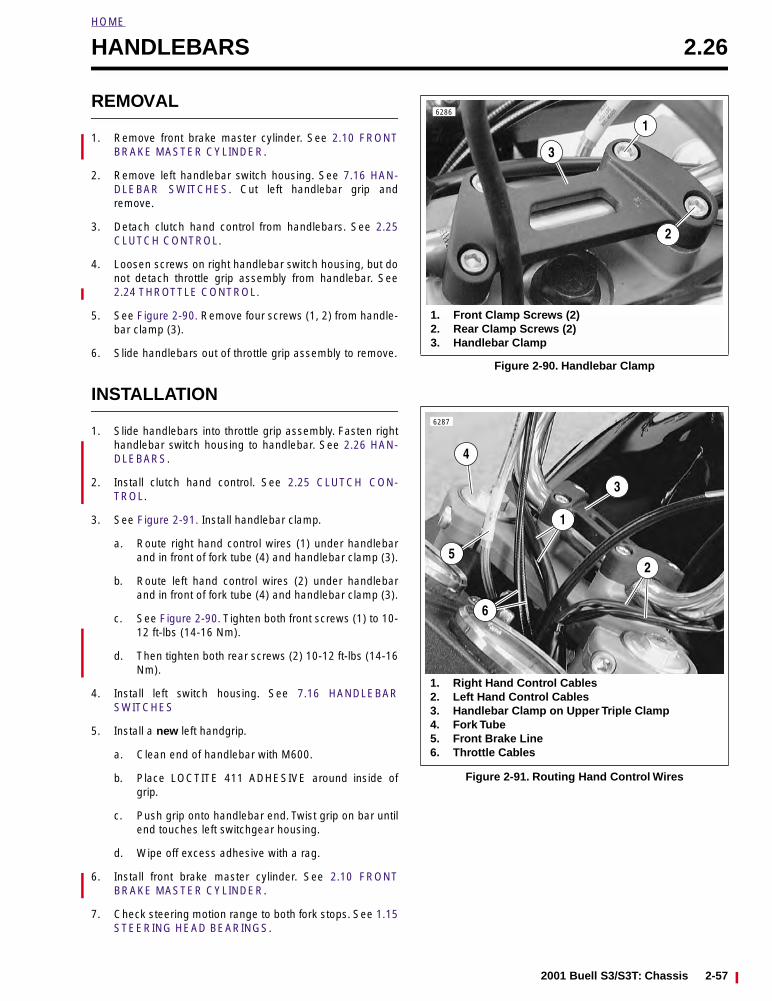
HOME
HANDLEBARS 2.26
REMOVAL
1. Remove front brake master cylinder. See 2.10 FRONTBRAKE MASTER CYLINDER.
2. Remove left handlebar switch housing. See 7.16 HAN-DLEBAR SWITCHES. Cut left handlebar grip andremove.
3. Detach clutch hand control from handlebars. See 2.25CLUTCH CONTROL.
4. Loosen screws on right handlebar switch housing, but donot detach throttle grip assembly from handlebar. See2.24 THROTTLE CONTROL.
5. See Figure 2-90. Remove four screws (1, 2) from handle-bar clamp (3).
6. Slide handlebars out of throttle grip assembly to remove.
INSTALLATION
1. Slide handlebars into throttle grip assembly. Fasten righthandlebar switch housing to handlebar. See 2.26 HAN-DLEBARS.
2. Install clutch hand control. See 2.25 CLUTCH CON-TROL.
3. See Figure 2-91. Install handlebar clamp.
a. Route right hand control wires (1) under handlebarand in front of fork tube (4) and handlebar clamp (3).
b. Route left hand control wires (2) under handlebarand in front of fork tube (4) and handlebar clamp (3).
c. See Figure 2-90. Tighten both front screws (1) to 10-12 ft-lbs (14-16 Nm).
d. Then tighten both rear screws (2) 10-12 ft-lbs (14-16Nm).
4. Install left switch housing. See 7.16 HANDLEBARSWITCHES
5. Install a new left handgrip.
a. Clean end of handlebar with M600.
b. Place LOCTITE 411 ADHESIVE around inside ofgrip.
c. Push grip onto handlebar end. Twist grip on bar untilend touches left switchgear housing.
d. Wipe off excess adhesive with a rag.
6. Install front brake master cylinder. See 2.10 FRONTBRAKE MASTER CYLINDER.
7. Check steering motion range to both fork stops. See 1.15STEERING HEAD BEARINGS.
Figure 2-90. Handlebar Clamp
Figure 2-91. Routing Hand Control Wires
6286
1. Front Clamp Screws (2)2. Rear Clamp Screws (2)3. Handlebar Clamp
2
1
3
6287
1. Right Hand Control Cables2. Left Hand Control Cables3. Handlebar Clamp on Upper Triple Clamp4. Fork Tube5. Front Brake Line6. Throttle Cables
2
1
3
4
5
6
2001 Buell S3/S3T: Chassis 2-57
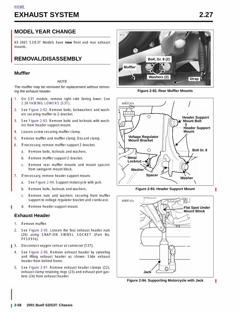
HOME
EXHAUST SYSTEM 2.27
MODEL YEAR CHANGE
All 2001 S3/S3T Models have new front and rear exhaustmounts.
REMOVAL/DISASSEMBLY
Muffler
NOTE
The muffler may be removed for replacement without remov-ing the exhaust header.
1. On S3T models, remove right side fairing lower. See2.38 FAIRING LOWERS (S3T).
2. See Figure 2-92. Remove bolts, lockwashers and wash-ers securing muffler to Z-bracket.
3. See Figure 2-93. Remove bolts and locknuts with wash-ers from header support mount.
4. Loosen screw securing muffler clamp.
5. Remove muffler and muffler clamp. Discard clamp.
6. If necessary, remove muffler support Z-bracket.
a. Remove bolts, locknuts and washers.
b. Remove muffler support Z-bracket.
c. Remove rear muffler mounts and mount spacersfrom swingarm mount block.
7. If necessary, remove header support mount.
a. See Figure 2-94. Support motorcycle with jack.
b. Remove bolts, locknuts and washers.
c. Remove nuts and washers securing front mufflersupport to voltage regulator bracket and crankcase.
d. Remove header support mount.
Exhaust Header
1. Remove muffler.
2. See Figure 2-95. Loosen the four exhaust header nuts(20) using SNAP-ON SWIVEL SOCKET (Part No.PFSX916).
3. Disconnect oxygen sensor at connector [137].
4. See Figure 2-96. Remove exhaust header by swivelingand lifting exhaust header as shown. Slide exhaustheader from behind frame.
5. See Figure 2-97. Remove exhaust header clamps (22),exhaust clamp retaining rings (23) and exhaust port gas-kets (24) from exhaust header.
Figure 2-92. Rear Muffler Mounts
Figure 2-93. Header Support Mount
Figure 2-94. Supporting Motorcycle with Jack
6751
StrapWashers (2)
Bolt, Gr. 8 (2)
Muffler
b0837x2x
Voltage RegulatorMount Bracket
Bolt Gr. 8
Header Support
Washer
Washer
Spacer
MetalLocknut
Header SupportMount
)Mount Bolt
Flat Spot UnderMount Block
Jack
b0887x2x
2-58 2001 Buell S3/S3T: Chassis
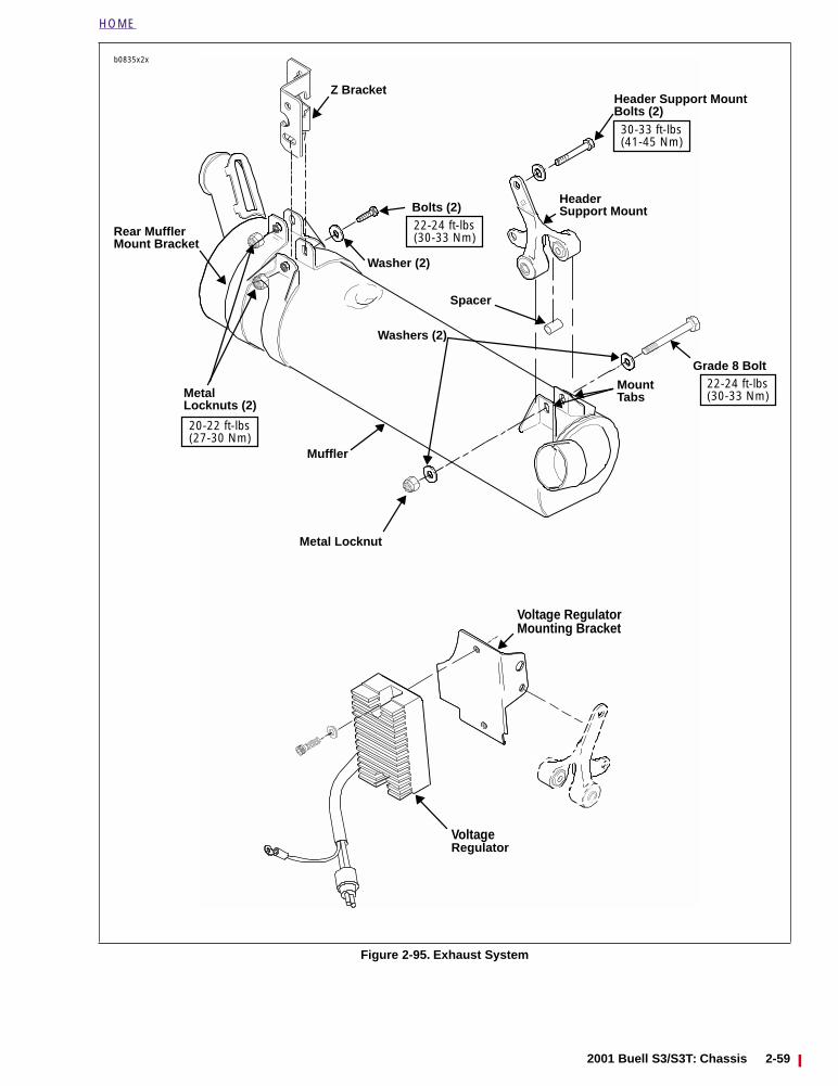
HOME
Figure 2-95. Exhaust System
b0835x2x
HeaderSupport Mount
Grade 8 Bolt
Washers (2)
Metal Locknut
Metal
Bolts (2)
Washer (2)
Z Bracket
Muffler
VoltageRegulator
Voltage RegulatorMounting Bracket
Header Support MountBolts (2)
Rear MufflerMount Bracket
MountTabs
Locknuts (2)
Spacer
20-22 ft-lbs(27-30 Nm)
22-24 ft-lbs(30-33 Nm)
22-24 ft-lbs(30-33 Nm)
30-33 ft-lbs(41-45 Nm)
2001 Buell S3/S3T: Chassis 2-59
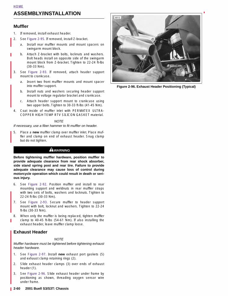
HOME
ASSEMBLY/INSTALLATION
Muffler
1. If removed, install exhaust header.
2. See Figure 2-95. If removed, install Z-bracket.
a. Install rear muffler mounts and mount spacers onswingarm mount block.
b. Attach Z-bracket with bolts, locknuts and washers.Bolt heads install on opposite side of the swingarmmount block from Z-bracket. Tighten to 22-24 ft-lbs(30-33 Nm).
3. See Figure 2-93. If removed, attach header supportmount to crankcase.
a. Insert two front muffler mounts and mount spacerinto muffler support.
b. Install nuts and washers securing header supportmount to voltage regulator bracket and crankcase.
c. Attach header support mount to crankcase usingtwo upper bolts. Tighten to 30-33 ft-lbs (41-45 Nm).
4. Coat inside of muffler inlet with PERMATEX ULTRA-COPPER HIGH TEMP RTV SILICON GASKET material.
NOTEIf necessary, use a fiber hammer to fit muffler on header.
5. Place a new muffler clamp over muffler inlet. Place muf-fler and clamp on end of exhaust header. Snug clampbut do not tighten.
11WARNING1WARNING
Before tightening muffler hardware, position muffler toprovide adequate clearance from rear shock absorber,side stand spring post and rear tire. Failure to provideadequate clearance may cause loss of control duringmotorcycle operation which could result in death or seri-ous injury.
6. See Figure 2-92. Position muffler and install to rearmounting support and weldnuts in rear muffler strapswith two sets of bolts, washers and locknuts. Tighten to22-24 ft-lbs (30-33 Nm).
7. See Figure 2-93. Secure muffler to header supportmount with bolt, locknut and washers. Tighten to 22-24ft-lbs (30-33 Nm).
8. When only the muffler is being replaced, tighten mufflerclamp to 40-45 ft-lbs (54-61 Nm). If also installing theexhaust header, leave muffler clamp loose.
Exhaust Header
NOTEMuffler hardware must be tightened before tightening exhaustheader hardware.
1. See Figure 2-97. Install new exhaust port gaskets (5)and exhaust clamp retaining rings (2).
2. Slide exhaust header clamps (3) over ends of exhaustheader (1).
3. See Figure 2-96. Slide exhaust header under frame bypositioning as shown, threading oxygen sensor wireunder frame.
Figure 2-96. Exhaust Header Positioning (Typical)
6813
2-60 2001 Buell S3/S3T: Chassis
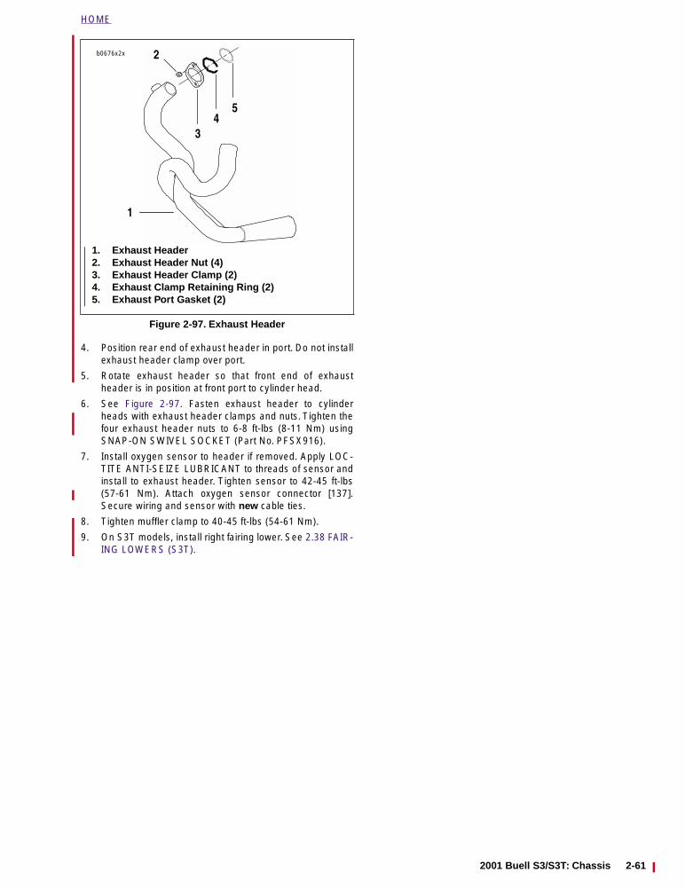
HOME
4. Position rear end of exhaust header in port. Do not installexhaust header clamp over port.
5. Rotate exhaust header so that front end of exhaustheader is in position at front port to cylinder head.
6. See Figure 2-97. Fasten exhaust header to cylinderheads with exhaust header clamps and nuts. Tighten thefour exhaust header nuts to 6-8 ft-lbs (8-11 Nm) usingSNAP-ON SWIVEL SOCKET (Part No. PFSX916).
7. Install oxygen sensor to header if removed. Apply LOC-TITE ANTI-SEIZE LUBRICANT to threads of sensor andinstall to exhaust header. Tighten sensor to 42-45 ft-lbs(57-61 Nm). Attach oxygen sensor connector [137].Secure wiring and sensor with new cable ties.
8. Tighten muffler clamp to 40-45 ft-lbs (54-61 Nm).
9. On S3T models, install right fairing lower. See 2.38 FAIR-ING LOWERS (S3T).
Figure 2-97. Exhaust Header
1. Exhaust Header2. Exhaust Header Nut (4)3. Exhaust Header Clamp (2)4. Exhaust Clamp Retaining Ring (2)5. Exhaust Port Gasket (2)
b0676x2x
1
54
3
2
2001 Buell S3/S3T: Chassis 2-61
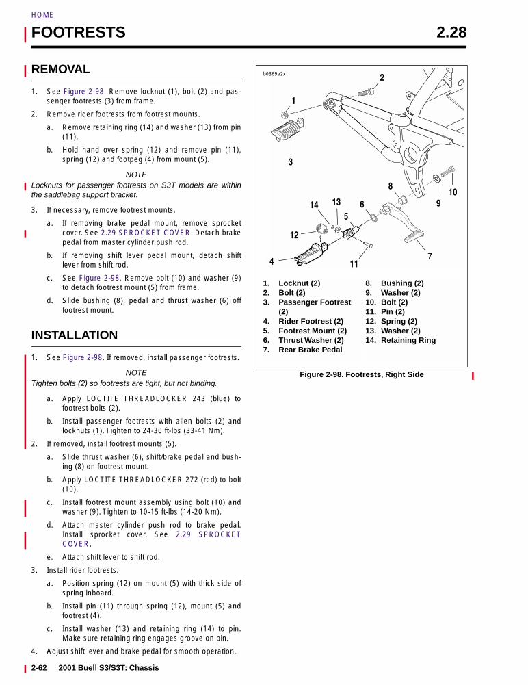
HOME
FOOTRESTS 2.28
REMOVAL
1. See Figure 2-98. Remove locknut (1), bolt (2) and pas-senger footrests (3) from frame.
2. Remove rider footrests from footrest mounts.
a. Remove retaining ring (14) and washer (13) from pin(11).
b. Hold hand over spring (12) and remove pin (11),spring (12) and footpeg (4) from mount (5).
NOTELocknuts for passenger footrests on S3T models are withinthe saddlebag support bracket.
3. If necessary, remove footrest mounts.
a. If removing brake pedal mount, remove sprocketcover. See 2.29 SPROCKET COVER. Detach brakepedal from master cylinder push rod.
b. If removing shift lever pedal mount, detach shiftlever from shift rod.
c. See Figure 2-98. Remove bolt (10) and washer (9)to detach footrest mount (5) from frame.
d. Slide bushing (8), pedal and thrust washer (6) offfootrest mount.
INSTALLATION
1. See Figure 2-98. If removed, install passenger footrests.
NOTETighten bolts (2) so footrests are tight, but not binding.
a. Apply LOCTITE THREADLOCKER 243 (blue) tofootrest bolts (2).
b. Install passenger footrests with allen bolts (2) andlocknuts (1). Tighten to 24-30 ft-lbs (33-41 Nm).
2. If removed, install footrest mounts (5).
a. Slide thrust washer (6), shift/brake pedal and bush-ing (8) on footrest mount.
b. Apply LOCTITE THREADLOCKER 272 (red) to bolt(10).
c. Install footrest mount assembly using bolt (10) andwasher (9). Tighten to 10-15 ft-lbs (14-20 Nm).
d. Attach master cylinder push rod to brake pedal.Install sprocket cover. See 2.29 SPROCKETCOVER.
e. Attach shift lever to shift rod.
3. Install rider footrests.
a. Position spring (12) on mount (5) with thick side ofspring inboard.
b. Install pin (11) through spring (12), mount (5) andfootrest (4).
c. Install washer (13) and retaining ring (14) to pin.Make sure retaining ring engages groove on pin.
4. Adjust shift lever and brake pedal for smooth operation.
Figure 2-98. Footrests, Right Side
b0369a2x
1. Locknut (2)2. Bolt (2)3. Passenger Footrest
(2)4. Rider Footrest (2)5. Footrest Mount (2)6. Thrust Washer (2)7. Rear Brake Pedal
8. Bushing (2)9. Washer (2)10. Bolt (2)11. Pin (2)12. Spring (2)13. Washer (2)14. Retaining Ring
3
11
1
95
7
2
8
12
610
4
14 13
2-62 2001 Buell S3/S3T: Chassis
HOME
SPROCKET COVER 2.29
MODEL YEAR CHANGE
The sprocket cover on 2001 Buell Air Twin Models has beenmodified from previous years to allow for more clearance withthe new rear isolators.
REMOVAL/DISASSEMBLY
1. See Figure 2-99. On S3 models, remove locknut andwasher from swingarm/drive support.
2. See Figure 2-100. On S3T models, remove screw onfairing lower. Remove bracket from stud.
3. See Figure 2-99. Remove two screws from swingarm/drive support.
4. Remove sprocket cover forward screw, washer andspacer.
5. Remove swingarm drive/support and sprocket cover asan assembly.
6. Remove two screws to separate sprocket cover fromswingarm/drive support.
ASSEMBLY/INSTALLATION
1. See Figure 2-99. If removed, attach sprocket cover toswingarm/drive support.
a. Place sprocket cover behind swingarm/drive sup-port. Align holes in cover with holes in support.
b. Apply LOCTITE THREADLOCKER 243 (blue) toboth screws.
c. Install screws. Tighten to 12-17 in-lbs (1-2 Nm).
2. Apply LOCTITE THREADLOCKER 243 (blue) to forwardscrew. Install sprocket cover assembly with screw,washer and spacer. Tighten to 48-72 in-lbs (5-9 Nm).
3. Apply LOCTITE THREADLOCKER 272 (red) to twoswingarm/drive support screws and install. Tightenscrews to 20-25 ft-lbs (27-34 Nm).
4. See Figure 2-100. On S3T models, place fairing lowerbracket on stud. Fasten fairing lower to bracket usingscrew.
5. See Figure 2-99. On S3 models, install locknut andwasher. Tighten locknut to 30-35 ft-lbs (41-47 Nm).
Figure 2-99. Sprocket Cover
Figure 2-100. S3T Fairing Lower Mount
b0204x2a
20-25 ft-lbs(27-34 Nm)
Screws (2)
Locknut30-35 ft-lbs(41-47 Nm)
Swingarm/DriveSupport
Red Loctite
Screw48-72 in-lbs(5-9 Nm)Blue Loctite
Screws (2)
Spacer
Sprocket Cover
12-17 in-lbs(1-2 Nm)Purple Loctite
Spacer
1
8308
3
4
2
1. Nut2. Bracket3. Screw and Wellnut4. Right Fairing Lower
2001 Buell S3/S3T: Chassis 2-63
HOME
STONE GUARD 2.30
REMOVAL
1. See Figure 2-101. Remove two screws (1) and washers(2) securing lower belt guard (3) to swing arm.
2. Remove lower belt guard (3), stone guard (4) and well-nuts (5) from swing arm.
INSTALLATION
1. See Figure 2-101. Position stone guard (4) with wellnuts(5) and lower belt guard (3) on swing arm.
2. Secure with two screws (1) and washers (2).
Figure 2-101. Stone Guard
b0612x2x
1. Screw (2)2. Washer (2)3. Lower Belt Guard4. Stone Guard5. Wellnut (2)
1
4
32
5
2-64 2001 Buell S3/S3T: Chassis
HOME
FRONT FENDER 2.31
REMOVAL
1. Remove front wheel. See 2.5 FRONT WHEEL.
2. See Figure 2-102. Remove both lower mounting screws(metric) and washers (7).
3. Remove upper mounting screws (1, 5) and washer andspacer (3) on each side. Do not remove brake line guide(2) and speedometer cable guide (6) from around lines/cables unless necessary.
4. Carefully slide fender downward between fork legs.
INSTALLATION
1. Place washer and spacer (3) around brake line guide (2)as shown in Figure 2-102. The guide retaining looppoints outward and back. Install screw (1) throughassembly, but do not tighten at this time.
2. Place washer and spacer (3) around speedometer cableguide (6). The guide retaining loop points outward andback. Install screw (5) through assembly, but do nottighten at this time.
3. Install lower mounting screws (7) (metric). Plastic washerfits between fork leg and back of fender. Tighten to 10-15in-lbs (1-2 Nm).
4. Tighten upper mounting screws (1, 5) to 20-25 in-lbs (2-3 Nm).
5. Install front wheel. See 2.5 FRONT WHEEL.
Figure 2-102. Front Fender
b0407x2x
1. Screw2. Brake Line Guide3. Washer and Spacer (2)4. Locknut (2)5. Screw6. Speedometer Cable Guide7. Screw (metric) and Washer (2)8. Front Fender
13
5
7
4
8
3
2
6
2001 Buell S3/S3T: Chassis 2-65
HOME
REAR FENDER 2.32
REMOVAL
1. Have someone sit on the vehicle to compress the motor-cycle’s suspension.
2. See Figure 2-103. Remove two screws (1) and washers(2) from right side wellnuts (4).
3. Remove screw (5) and washer (6) from front wellnut (7).
4. Remove screw (8) washer (9) from brake line clamp onthe left side.
5. Pull fender over rear tire.
INSTALLATION
1. See Figure 2-104. Position fender over tire, making surethat the brake hose is on the outside of the fender asshown.
2. See Figure 2-103. Secure clamp with screw (8) andwasher (9).
3. Have someone sit on the motorcycle to compress themotorcycle’s suspension.
4. Apply LOCTITE THREADLOCKER 243 (blue) to allscrews.
a. Install screw (5) and washer (6) into wellnut (7).
b. Install screws (1) and washers (2) into wellnuts (4).
Figure 2-103. Rear Fender
Figure 2-104. Rear Fender With Brake Hose
1. Screw (2)2. Washer (2)3. Fender4. Wellnut (2)5. Screw6. Washer7. Wellnut8. Screw9. Washer
b0608x2x
1 2
3
9
4 5 6 7
8
6883
2-66 2001 Buell S3/S3T: Chassis
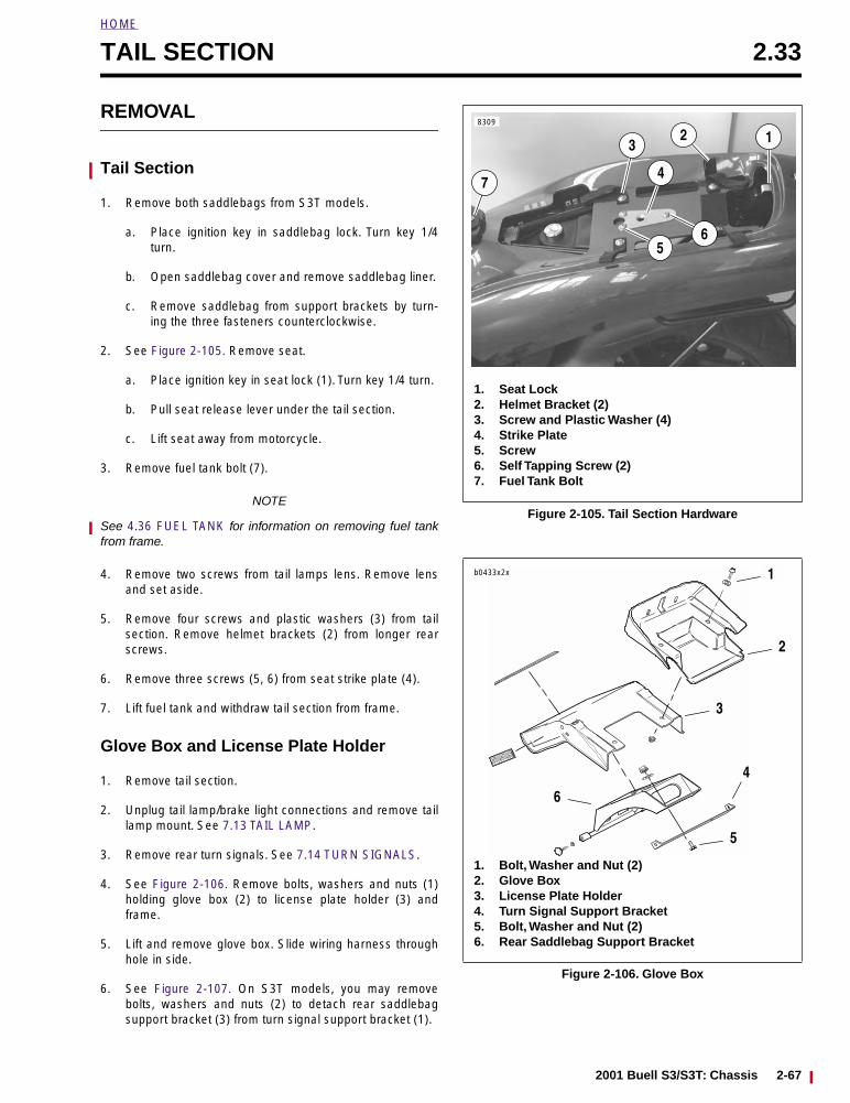
HOME
TAIL SECTION 2.33
REMOVAL
Tail Section
1. Remove both saddlebags from S3T models.
a. Place ignition key in saddlebag lock. Turn key 1/4turn.
b. Open saddlebag cover and remove saddlebag liner.
c. Remove saddlebag from support brackets by turn-ing the three fasteners counterclockwise.
2. See Figure 2-105. Remove seat.
a. Place ignition key in seat lock (1). Turn key 1/4 turn.
b. Pull seat release lever under the tail section.
c. Lift seat away from motorcycle.
3. Remove fuel tank bolt (7).
NOTE
See 4.36 FUEL TANK for information on removing fuel tankfrom frame.
4. Remove two screws from tail lamps lens. Remove lensand set aside.
5. Remove four screws and plastic washers (3) from tailsection. Remove helmet brackets (2) from longer rearscrews.
6. Remove three screws (5, 6) from seat strike plate (4).
7. Lift fuel tank and withdraw tail section from frame.
Glove Box and License Plate Holder
1. Remove tail section.
2. Unplug tail lamp/brake light connections and remove taillamp mount. See 7.13 TAIL LAMP.
3. Remove rear turn signals. See 7.14 TURN SIGNALS.
4. See Figure 2-106. Remove bolts, washers and nuts (1)holding glove box (2) to license plate holder (3) andframe.
5. Lift and remove glove box. Slide wiring harness throughhole in side.
6. See Figure 2-107. On S3T models, you may removebolts, washers and nuts (2) to detach rear saddlebagsupport bracket (3) from turn signal support bracket (1).
Figure 2-105. Tail Section Hardware
Figure 2-106. Glove Box
8309
123
5
74
1. Seat Lock2. Helmet Bracket (2)3. Screw and Plastic Washer (4)4. Strike Plate5. Screw 6. Self Tapping Screw (2)7. Fuel Tank Bolt
6
1
2
5
4
3
6
1. Bolt, Washer and Nut (2)2. Glove Box3. License Plate Holder4. Turn Signal Support Bracket5. Bolt, Washer and Nut (2)6. Rear Saddlebag Support Bracket
b0433x2x
2001 Buell S3/S3T: Chassis 2-67
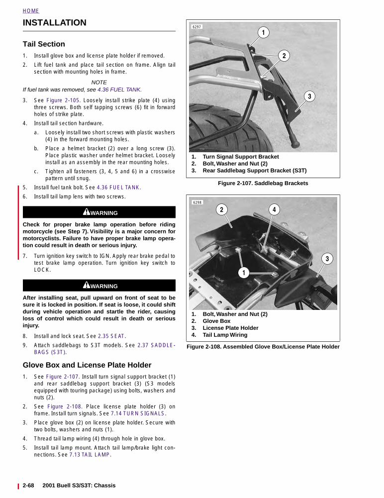
HOME
INSTALLATION
Tail Section1. Install glove box and license plate holder if removed.
2. Lift fuel tank and place tail section on frame. Align tailsection with mounting holes in frame.
NOTEIf fuel tank was removed, see 4.36 FUEL TANK.
3. See Figure 2-105. Loosely install strike plate (4) usingthree screws. Both self tapping screws (6) fit in forwardholes of strike plate.
4. Install tail section hardware.
a. Loosely install two short screws with plastic washers(4) in the forward mounting holes.
b. Place a helmet bracket (2) over a long screw (3).Place plastic washer under helmet bracket. Looselyinstall as an assembly in the rear mounting holes.
c. Tighten all fasteners (3, 4, 5 and 6) in a crosswisepattern until snug.
5. Install fuel tank bolt. See 4.36 FUEL TANK.
6. Install tail lamp lens with two screws.
11WARNING1WARNING
Check for proper brake lamp operation before ridingmotorcycle (see Step 7). Visibility is a major concern formotorcyclists. Failure to have proper brake lamp opera-tion could result in death or serious injury.
7. Turn ignition key switch to IGN. Apply rear brake pedal totest brake lamp operation. Turn ignition key switch toLOCK.
11WARNING1WARNING
After installing seat, pull upward on front of seat to besure it is locked in position. If seat is loose, it could shiftduring vehicle operation and startle the rider, causingloss of control which could result in death or seriousinjury.
8. Install and lock seat. See 2.35 SEAT.
9. Attach saddlebags to S3T models. See 2.37 SADDLE-BAGS (S3T).
Glove Box and License Plate Holder1. See Figure 2-107. Install turn signal support bracket (1)
and rear saddlebag support bracket (3) (S3 modelsequipped with touring package) using bolts, washers andnuts (2).
2. See Figure 2-108. Place license plate holder (3) onframe. Install turn signals. See 7.14 TURN SIGNALS.
3. Place glove box (2) on license plate holder. Secure withtwo bolts, washers and nuts (1).
4. Thread tail lamp wiring (4) through hole in glove box.
5. Install tail lamp mount. Attach tail lamp/brake light con-nections. See 7.13 TAIL LAMP.
Figure 2-107. Saddlebag Brackets
Figure 2-108. Assembled Glove Box/License Plate Holder
6297
3
1
2
1. Turn Signal Support Bracket2. Bolt, Washer and Nut (2)3. Rear Saddlebag Support Bracket (S3T)
6298
2
3
1
1. Bolt, Washer and Nut (2)2. Glove Box3. License Plate Holder4. Tail Lamp Wiring
4
2-68 2001 Buell S3/S3T: Chassis
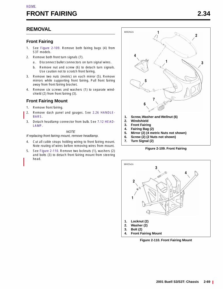
HOME
FRONT FAIRING 2.34
REMOVAL
Front Fairing1. See Figure 2-109. Remove both fairing bags (4) from
S3T models.
2. Remove both front turn signals (7).
a. Disconnect bullet connectors on turn signal wires.
b. Remove nut and screw (6) to detach turn signals.Use caution not to scratch front fairing.
3. Remove two nuts (metric) on each mirror (5). Removemirrors while supporting front fairing. Pull front fairingaway from front fairing bracket.
4. Remove six screws and washers (1) to separate wind-shield (2) from front fairing (3).
Front Fairing Mount1. Remove front fairing.
2. Remove dash panel and gauges. See 2.26 HANDLE-BARS.
3. Detach headlamp connector from bulb. See 7.12 HEAD-LAMP.
NOTEIf replacing front fairing mount, remove headlamp.
4. Cut all cable straps holding wiring to front fairing mount.Note routing of wires before removing wires from mount.
5. See Figure 2-110. Remove two locknuts (1), washers (2)and bolts (3) to detach front fairing mount from steeringhead.
Figure 2-109. Front Fairing
Figure 2-110. Front Fairing Mount
b0424x2x
1. Screw, Washer and Wellnut (6)2. Windshield3. Front Fairing4. Fairing Bag (2)5. Mirror (2) (4 metric Nuts not shown)6. Screw (2) (2 Nuts not shown)7. Turn Signal (2)
12
3
5
67
14
b0425x2x
3
2
1
4
1. Locknut (2)2. Washer (2)3. Bolt (2)4. Front Fairing Mount
2001 Buell S3/S3T: Chassis 2-69
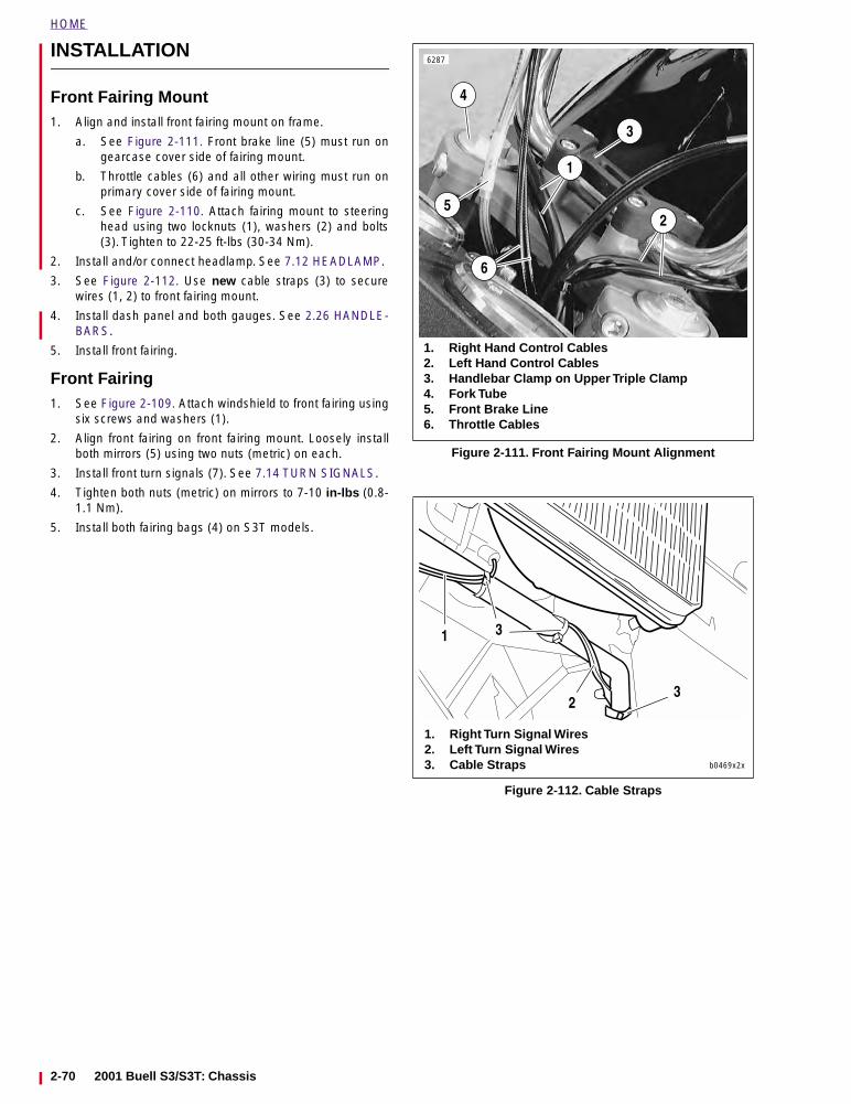
HOME
INSTALLATION
Front Fairing Mount1. Align and install front fairing mount on frame.
a. See Figure 2-111. Front brake line (5) must run ongearcase cover side of fairing mount.
b. Throttle cables (6) and all other wiring must run onprimary cover side of fairing mount.
c. See Figure 2-110. Attach fairing mount to steeringhead using two locknuts (1), washers (2) and bolts(3). Tighten to 22-25 ft-lbs (30-34 Nm).
2. Install and/or connect headlamp. See 7.12 HEADLAMP.
3. See Figure 2-112. Use new cable straps (3) to securewires (1, 2) to front fairing mount.
4. Install dash panel and both gauges. See 2.26 HANDLE-BARS.
5. Install front fairing.
Front Fairing1. See Figure 2-109. Attach windshield to front fairing using
six screws and washers (1).
2. Align front fairing on front fairing mount. Loosely installboth mirrors (5) using two nuts (metric) on each.
3. Install front turn signals (7). See 7.14 TURN SIGNALS.
4. Tighten both nuts (metric) on mirrors to 7-10 in-lbs (0.8-1.1 Nm).
5. Install both fairing bags (4) on S3T models.
Figure 2-111. Front Fairing Mount Alignment
Figure 2-112. Cable Straps
6287
1. Right Hand Control Cables2. Left Hand Control Cables3. Handlebar Clamp on Upper Triple Clamp4. Fork Tube5. Front Brake Line6. Throttle Cables
2
1
3
4
5
6
b0469x2x
1
1. Right Turn Signal Wires2. Left Turn Signal Wires3. Cable Straps
3
23
2-70 2001 Buell S3/S3T: Chassis
HOME
SEAT 2.35
REMOVAL
Seat1. See Figure 2-113. Place ignition key in seat lock. Turn
key 1/4 turn.
2. Pull seat release lever under the tail section.
3. Lift seat and remove.
Seat Lock1. Remove seat.
2. See Figure 2-114. Remove locknut (10) and star washer(9) from lock (2).
3. Slowly remove seat tang (8). As seat tang is lowered,cam (7) will follow. Note orientation of cam (top/bottomand slot position) for later installation.
4. Remove nut (6).
5. Remove D-washer (5) and O-ring (4).
6. Pull lock (2) and O-ring (3) from top of tail section.
Seat Release1. Remove seat.
2. See Figure 2-115. Remove shoulder bolt (1), spring (2)and washer (3) from frame.
NOTEDepending upon vehicle production date, some S3T modelsmay have a remote seat release handle. This handle attachesto the seat latch lever via a cable.
3. Remove seat latch lever (4) and bushing (5).
INSTALLATION
Seat1. See Figure 2-116. Install seat by sliding metal locating
tab (2) on bottom of seat under frame tab (3).
2. Press down on seat until seat release lever clicks.
11WARNING1WARNING
After installing seat, pull upward on front of seat to besure it is locked in position. If seat is loose, it could shiftduring vehicle operation and startle the rider, causingloss of control which could result in death or seriousinjury.
3. See Figure 2-113. Turn ignition key 1/4 turn. Remove keyfrom seat lock.
NOTE● Seat lock must be in the locked position before ignition
key may be removed.
● See Figure 2-116. Metal tabs on tail section are helmetbrackets (1). Place helmet D-ring under tab. Install andlock seat to secure helmet for storage while motorcycleis stationary.
Figure 2-113. Removing Seat
Figure 2-114. Seat Lock
Figure 2-115. Seat Release
6288
1. Key2. Lock3. O-Ring4. O-Ring5. D-Washer6. Nut7. Cam8. Seat Tang9. Star Washer10. Locknut
b0432x2x
1
2
10
67
89
3
54
1. Shoulder Bolt2. Spring3. Washer4. Seat Latch Lever5. Bushing
b0434x2x
5
12
34
2001 Buell S3/S3T: Chassis 2-71
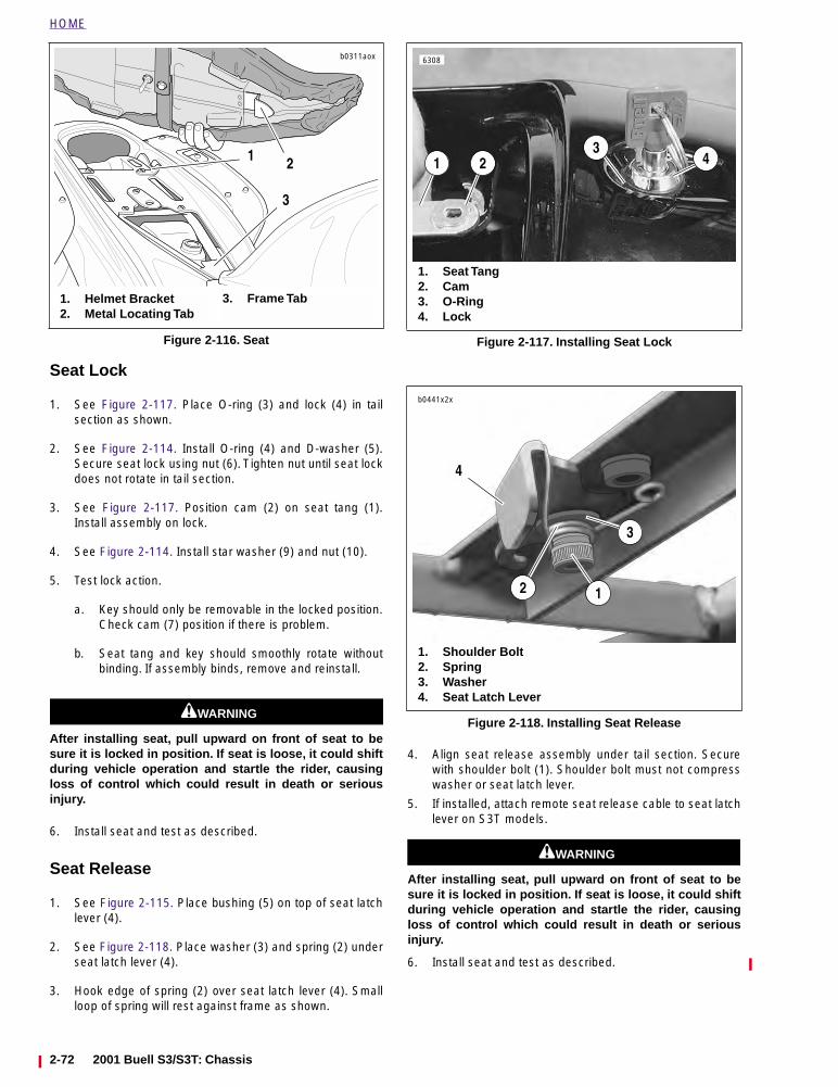
HOME
Seat Lock
1. See Figure 2-117. Place O-ring (3) and lock (4) in tailsection as shown.
2. See Figure 2-114. Install O-ring (4) and D-washer (5).Secure seat lock using nut (6). Tighten nut until seat lockdoes not rotate in tail section.
3. See Figure 2-117. Position cam (2) on seat tang (1).Install assembly on lock.
4. See Figure 2-114. Install star washer (9) and nut (10).
5. Test lock action.
a. Key should only be removable in the locked position.Check cam (7) position if there is problem.
b. Seat tang and key should smoothly rotate withoutbinding. If assembly binds, remove and reinstall.
11WARNING1WARNING
After installing seat, pull upward on front of seat to besure it is locked in position. If seat is loose, it could shiftduring vehicle operation and startle the rider, causingloss of control which could result in death or seriousinjury.
6. Install seat and test as described.
Seat Release
1. See Figure 2-115. Place bushing (5) on top of seat latchlever (4).
2. See Figure 2-118. Place washer (3) and spring (2) underseat latch lever (4).
3. Hook edge of spring (2) over seat latch lever (4). Smallloop of spring will rest against frame as shown.
4. Align seat release assembly under tail section. Securewith shoulder bolt (1). Shoulder bolt must not compresswasher or seat latch lever.
5. If installed, attach remote seat release cable to seat latchlever on S3T models.
11WARNING1WARNING
After installing seat, pull upward on front of seat to besure it is locked in position. If seat is loose, it could shiftduring vehicle operation and startle the rider, causingloss of control which could result in death or seriousinjury.
6. Install seat and test as described.
Figure 2-116. Seat
b0311aox
1
1. Helmet Bracket2. Metal Locating Tab
3. Frame Tab
2
3
Figure 2-117. Installing Seat Lock
Figure 2-118. Installing Seat Release
1
6308
2
1. Seat Tang2. Cam3. O-Ring4. Lock
34
1
1. Shoulder Bolt2. Spring3. Washer4. Seat Latch Lever
2
3
b0441x2x
4
2-72 2001 Buell S3/S3T: C
hassis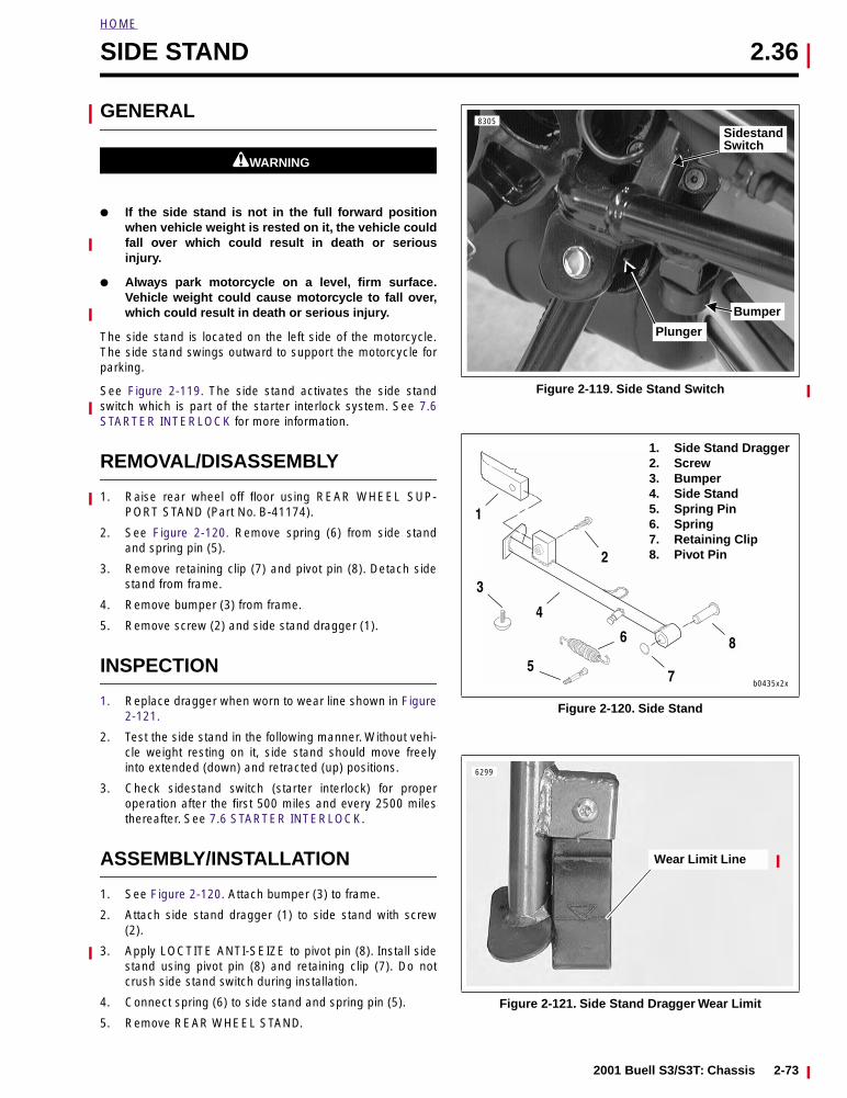
HOME
SIDE STAND 2.36
GENERAL
11WARNING1WARNING
● If the side stand is not in the full forward positionwhen vehicle weight is rested on it, the vehicle couldfall over which could result in death or seriousinjury.
● Always park motorcycle on a level, firm surface.Vehicle weight could cause motorcycle to fall over,which could result in death or serious injury.
The side stand is located on the left side of the motorcycle.The side stand swings outward to support the motorcycle forparking.
See Figure 2-119. The side stand activates the side standswitch which is part of the starter interlock system. See 7.6STARTER INTERLOCK for more information.
REMOVAL/DISASSEMBLY
1. Raise rear wheel off floor using REAR WHEEL SUP-PORT STAND (Part No. B-41174).
2. See Figure 2-120. Remove spring (6) from side standand spring pin (5).
3. Remove retaining clip (7) and pivot pin (8). Detach sidestand from frame.
4. Remove bumper (3) from frame.
5. Remove screw (2) and side stand dragger (1).
INSPECTION
1. Replace dragger when worn to wear line shown in Figure2-121.
2. Test the side stand in the following manner. Without vehi-cle weight resting on it, side stand should move freelyinto extended (down) and retracted (up) positions.
3. Check sidestand switch (starter interlock) for properoperation after the first 500 miles and every 2500 milesthereafter. See 7.6 STARTER INTERLOCK.
ASSEMBLY/INSTALLATION
1. See Figure 2-120. Attach bumper (3) to frame.
2. Attach side stand dragger (1) to side stand with screw(2).
3. Apply LOCTITE ANTI-SEIZE to pivot pin (8). Install sidestand using pivot pin (8) and retaining clip (7). Do notcrush side stand switch during installation.
4. Connect spring (6) to side stand and spring pin (5).
5. Remove REAR WHEEL STAND.
Figure 2-119. Side Stand Switch
Figure 2-120. Side Stand
Figure 2-121. Side Stand Dragger Wear Limit
SidestandSwitch
Plunger
8305
Bumper
1
4
3
75
6
2
1. Side Stand Dragger2. Screw3. Bumper4. Side Stand5. Spring Pin6. Spring7. Retaining Clip8. Pivot Pin
8
b0435x2x
Wear Limit Line
6299
2001 Buell S3/S3T: Chassis 2-73
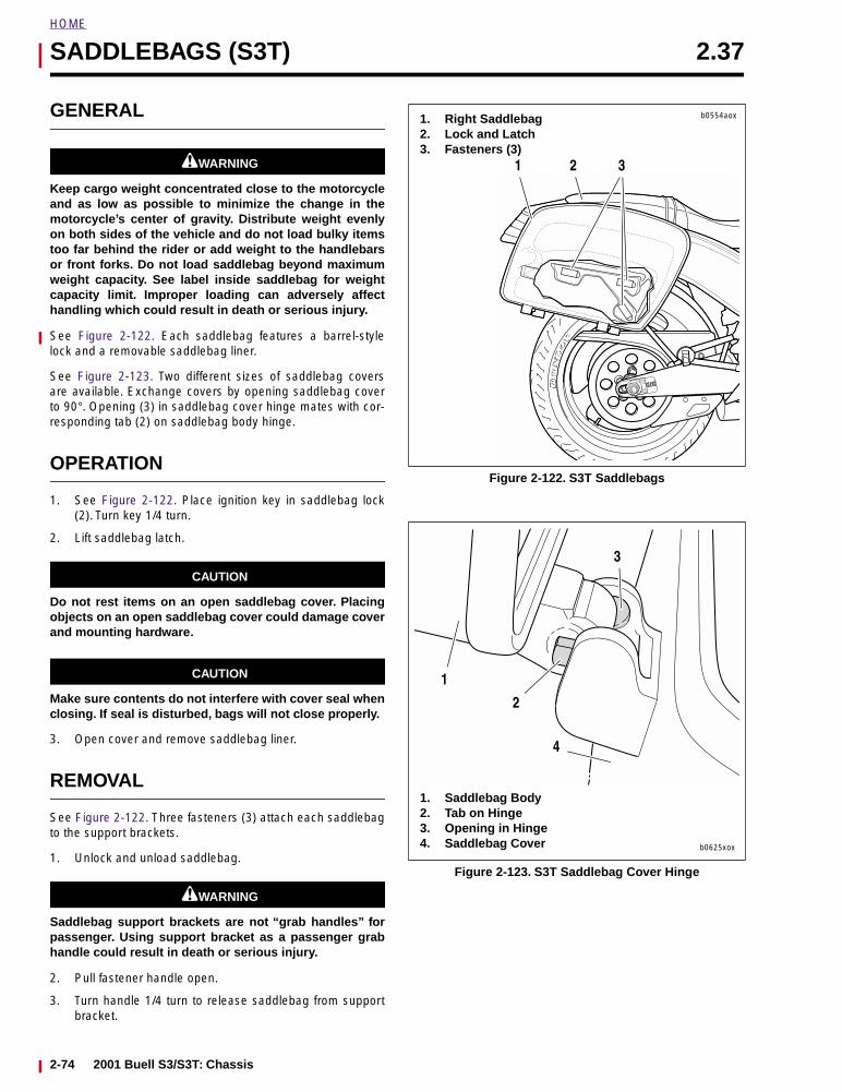
HOME
SADDLEBAGS (S3T) 2.37
GENERAL
11WARNING1WARNING
Keep cargo weight concentrated close to the motorcycleand as low as possible to minimize the change in themotorcycle’s center of gravity. Distribute weight evenlyon both sides of the vehicle and do not load bulky itemstoo far behind the rider or add weight to the handlebarsor front forks. Do not load saddlebag beyond maximumweight capacity. See label inside saddlebag for weightcapacity limit. Improper loading can adversely affecthandling which could result in death or serious injury.
See Figure 2-122. Each saddlebag features a barrel-stylelock and a removable saddlebag liner.
See Figure 2-123. Two different sizes of saddlebag coversare available. Exchange covers by opening saddlebag coverto 90°. Opening (3) in saddlebag cover hinge mates with cor-responding tab (2) on saddlebag body hinge.
OPERATION
1. See Figure 2-122. Place ignition key in saddlebag lock(2). Turn key 1/4 turn.
2. Lift saddlebag latch.
CAUTION
Do not rest items on an open saddlebag cover. Placingobjects on an open saddlebag cover could damage coverand mounting hardware.
CAUTION
Make sure contents do not interfere with cover seal whenclosing. If seal is disturbed, bags will not close properly.
3. Open cover and remove saddlebag liner.
REMOVAL
See Figure 2-122. Three fasteners (3) attach each saddlebagto the support brackets.
1. Unlock and unload saddlebag.
11WARNING1WARNING
Saddlebag support brackets are not “grab handles” forpassenger. Using support bracket as a passenger grabhandle could result in death or serious injury.
2. Pull fastener handle open.
3. Turn handle 1/4 turn to release saddlebag from supportbracket.
Figure 2-122. S3T Saddlebags
Figure 2-123. S3T Saddlebag Cover Hinge
1 2 3
1. Right Saddlebag2. Lock and Latch3. Fasteners (3)
b0554aox
b0625xox
1. Saddlebag Body2. Tab on Hinge3. Opening in Hinge4. Saddlebag Cover
1
2
3
4
2-74 2001 Buell S3/S3T: Chassis
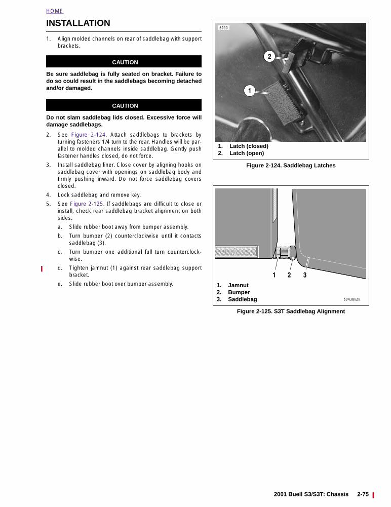
HOME
INSTALLATION
1. Align molded channels on rear of saddlebag with supportbrackets.
CAUTION
Be sure saddlebag is fully seated on bracket. Failure todo so could result in the saddlebags becoming detachedand/or damaged.
CAUTION
Do not slam saddlebag lids closed. Excessive force willdamage saddlebags.
2. See Figure 2-124. Attach saddlebags to brackets byturning fasteners 1/4 turn to the rear. Handles will be par-allel to molded channels inside saddlebag. Gently pushfastener handles closed, do not force.
3. Install saddlebag liner. Close cover by aligning hooks onsaddlebag cover with openings on saddlebag body andfirmly pushing inward. Do not force saddlebag coversclosed.
4. Lock saddlebag and remove key.
5. See Figure 2-125. If saddlebags are difficult to close orinstall, check rear saddlebag bracket alignment on bothsides.
a. Slide rubber boot away from bumper assembly.
b. Turn bumper (2) counterclockwise until it contactssaddlebag (3).
c. Turn bumper one additional full turn counterclock-wise.
d. Tighten jamnut (1) against rear saddlebag supportbracket.
e. Slide rubber boot over bumper assembly.
Figure 2-124. Saddlebag Latches
Figure 2-125. S3T Saddlebag Alignment
1
6990
2
1. Latch (closed)2. Latch (open)
1. Jamnut2. Bumper3. Saddlebag
1 2 3
b0438x2x
2001 Buell S3/S3T: Chassis 2-75
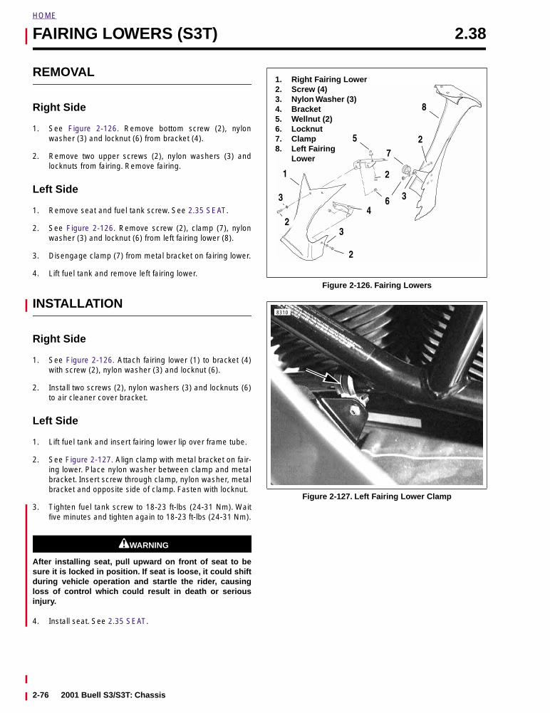
HOME
FAIRING LOWERS (S3T) 2.38
REMOVAL
Right Side
1. See Figure 2-126. Remove bottom screw (2), nylonwasher (3) and locknut (6) from bracket (4).
2. Remove two upper screws (2), nylon washers (3) andlocknuts from fairing. Remove fairing.
Left Side
1. Remove seat and fuel tank screw. See 2.35 SEAT.
2. See Figure 2-126. Remove screw (2), clamp (7), nylonwasher (3) and locknut (6) from left fairing lower (8).
3. Disengage clamp (7) from metal bracket on fairing lower.
4. Lift fuel tank and remove left fairing lower.
INSTALLATION
Right Side
1. See Figure 2-126. Attach fairing lower (1) to bracket (4)with screw (2), nylon washer (3) and locknut (6).
2. Install two screws (2), nylon washers (3) and locknuts (6)to air cleaner cover bracket.
Left Side
1. Lift fuel tank and insert fairing lower lip over frame tube.
2. See Figure 2-127. Align clamp with metal bracket on fair-ing lower. Place nylon washer between clamp and metalbracket. Insert screw through clamp, nylon washer, metalbracket and opposite side of clamp. Fasten with locknut.
3. Tighten fuel tank screw to 18-23 ft-lbs (24-31 Nm). Waitfive minutes and tighten again to 18-23 ft-lbs (24-31 Nm).
11WARNING1WARNING
After installing seat, pull upward on front of seat to besure it is locked in position. If seat is loose, it could shiftduring vehicle operation and startle the rider, causingloss of control which could result in death or seriousinjury.
4. Install seat. See 2.35 SEAT.
Figure 2-126. Fairing Lowers
Figure 2-127. Left Fairing Lower Clamp
1. Right Fairing Lower2. Screw (4)3. Nylon Washer (3) 4. Bracket 5. Wellnut (2)6. Locknut7. Clamp8. Left Fairing
Lower
1
8
7
5
3
2
2
4
2
63
2
3
8310
2-76 2001 Buell S3/S3T: Chassis
ENGINE 3
SUBJECT PAGE NO.
3.1 Specifications . . . . . . . . . . . . . . . . . . . . . . . . . . . . . . . . . . . . . . . . . . . . . . . . . . 3-13.2 Engine . . . . . . . . . . . . . . . . . . . . . . . . . . . . . . . . . . . . . . . . . . . . . . . . . . . . . . . 3-53.3 Stripping Motorcycle For Engine Repair . . . . . . . . . . . . . . . . . . . . . . . . . . . . . 3-83.4 Installing The Engine . . . . . . . . . . . . . . . . . . . . . . . . . . . . . . . . . . . . . . . . . . . . 3-103.5 Cylinder Head . . . . . . . . . . . . . . . . . . . . . . . . . . . . . . . . . . . . . . . . . . . . . . . . . 3-123.6 Cylinder and Piston . . . . . . . . . . . . . . . . . . . . . . . . . . . . . . . . . . . . . . . . . . . . . 3-243.7 Lubrication System . . . . . . . . . . . . . . . . . . . . . . . . . . . . . . . . . . . . . . . . . . . . . 3-313.8 Oil Hose Routing . . . . . . . . . . . . . . . . . . . . . . . . . . . . . . . . . . . . . . . . . . . . . . . 3-323.9 Oil Tank . . . . . . . . . . . . . . . . . . . . . . . . . . . . . . . . . . . . . . . . . . . . . . . . . . . . . . 3-333.10 Oil Pressure Indicator Switch . . . . . . . . . . . . . . . . . . . . . . . . . . . . . . . . . . . . . 3-343.11 Crankcase Breathing System . . . . . . . . . . . . . . . . . . . . . . . . . . . . . . . . . . . . 3-353.12 Oiling System (Color Foldout) . . . . . . . . . . . . . . . . . . . . . . . . . . . . . . . . . . . . 3-363.13 Oil Pump . . . . . . . . . . . . . . . . . . . . . . . . . . . . . . . . . . . . . . . . . . . . . . . . . . . . 3-373.14 Oil Filter Mount . . . . . . . . . . . . . . . . . . . . . . . . . . . . . . . . . . . . . . . . . . . . . . . 3-403.15 Hydraulic Lifters . . . . . . . . . . . . . . . . . . . . . . . . . . . . . . . . . . . . . . . . . . . . . . . 3-413.16 Gearcase Cover and Cam Gears . . . . . . . . . . . . . . . . . . . . . . . . . . . . . . . . . 3-433.17 Crankcase . . . . . . . . . . . . . . . . . . . . . . . . . . . . . . . . . . . . . . . . . . . . . . . . . . . 3-50
Table Of Contents

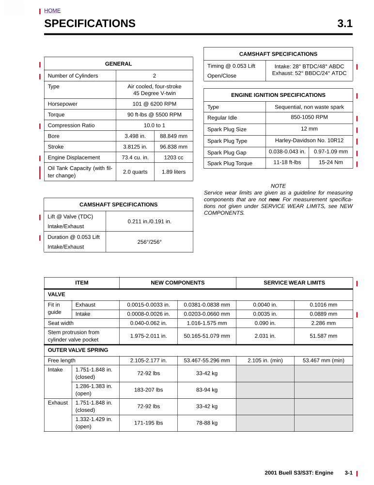
HOME
3
SPECIFICATIONS 3.1
NOTEService wear limits are given as a guideline for measuringcomponents that are not new. For measurement specifica-tions not given under SERVICE WEAR LIMITS, see NEWCOMPONENTS.
GENERAL
Number of Cylinders 2
Type Air cooled, four-stroke45 Degree V-twin
Horsepower 101 @ 6200 RPM
Torque 90 ft-lbs @ 5500 RPM
Compression Ratio 10.0 to 1
Bore 3.498 in. 88.849 mm
Stroke 3.8125 in. 96.838 mm
Engine Displacement 73.4 cu. in. 1203 cc
Oil Tank Capacity (with fil-ter change)
2.0 quarts 1.89 liters
CAMSHAFT SPECIFICATIONS
Lift @ Valve (TDC)
Intake/Exhaust0.211 in./0.191 in.
Duration @ 0.053 Lift
Intake/Exhaust256°/256°
Timing @ 0.053 Lift
Open/Close
Intake: 28° BTDC/48° ABDCExhaust: 52° BBDC/24° ATDC
ENGINE IGNITION SPECIFICATIONS
Type Sequential, non waste spark
Regular Idle 850-1050 RPM
Spark Plug Size 12 mm
Spark Plug Type Harley-Davidson No. 10R12
Spark Plug Gap 0.038-0.043 in. 0.97-1.09 mm
Spark Plug Torque 11-18 ft-lbs 15-24 Nm
CAMSHAFT SPECIFICATIONS
ITEM NEW COMPONENTS SERVICE WEAR LIMITS
VALVE
Fit in guide
Exhaust 0.0015-0.0033 in. 0.0381-0.0838 mm 0.0040 in. 0.1016 mm
Intake 0.0008-0.0026 in. 0.0203-0.0660 mm 0.0035 in. 0.0889 mm
Seat width 0.040-0.062 in. 1.016-1.575 mm 0.090 in. 2.286 mm
Stem protrusion fromcylinder valve pocket
1.975-2.011 in. 50.165-51.079 mm 2.031 in. 51.587 mm
OUTER VALVE SPRING
Free length 2.105-2.177 in. 53.467-55.296 mm 2.105 in. (min) 53.467 mm (min)
Intake 1.751-1.848 in. (closed)
72-92 lbs 33-42 kg
1.286-1.383 in. (open)
183-207 lbs 83-94 kg
Exhaust 1.751-1.848 in. (closed)
72-92 lbs 33-42 kg
1.332-1.429 in. (open)
171-195 lbs 78-88 kg
2001 Buell S3/S3T: Engine 3-1
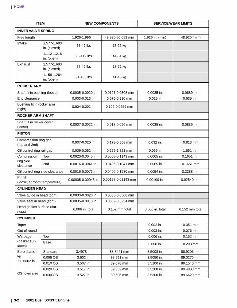
HOME
ITEM NEW COMPONENTS SERVICE WEAR LIMITS
INNER VALVE SPRING
Free length 1.926-1.996 in. 48.920-50.698 mm 1.926 in. (min) 48.920 (min)
Intake 1.577-1.683 in. (closed)
38-49 lbs 17-22 kg
1.112-1.218 in. (open)
98-112 lbs 44-51 kg
Exhaust 1.577-1.683 in. (closed)
38-49 lbs 17-22 kg
1.158-1.264 in. (open)
91-106 lbs 41-48 kg
ROCKER ARM
Shaft fit in bushing (loose) 0.0005-0.0020 in. 0.0127-0.0508 mm 0.0035 in. 0.0889 mm
End clearance 0.003-0.013 in. 0.076-0.330 mm 0.025 in 0.635 mm
Bushing fit in rocker arm (tight)
0.004-0.002 in. 0.102-0.0559 mm
ROCKER ARM SHAFT
Shaft fit in rocker cover (loose)
0.0007-0.0022 in. 0.018-0.056 mm 0.0035 in. 0.0889 mm
PISTON
Compression ring gap (top and 2nd)
0.007-0.020 in. 0.178-0.508 mm 0.032 in. 0.813 mm
Oil control ring rail gap 0.009-0.052 in. 0.229-1.321 mm 0.065 in 1.651 mm
Compression ring sideclearance
Top 0.0020-0.0045 in. 0.0508-0.1143 mm 0.0065 in. 0.1651 mm
2nd 0.0016-0.0041 in. 0.0406-0.1041 mm 0.0065 in. 0.1651 mm
Oil control ring side clearance 0.0016-0.0076 in. 0.0406-0.1930 mm 0.0094 in. 0.2388 mm
Pin fit (loose, at room temperature)
0.00005-0.00045 in. 0.00127-0.01143 mm 0.00100 in. 0.02540 mm
CYLINDER HEAD
Valve guide in head (tight) 0.0033-0.0020 in. 0.0838-0.0508 mm
Valve seat in head (tight) 0.0035-0.0010 in. 0.0889-0.0254 mm
Head gasket surface (flat-ness)
0.006 in. total 0.152 mm total 0.006 in. total 0.152 mm total
CYLINDER
Taper 0.002 in. 0.051 mm
Out of round 0.003 in. 0.076 mm
Warpage (gasket sur-faces)
Top 0.006 in. 0.152 mm
Base 0.008 in. 0.203 mm
Bore diame-ter± 0.0002 in.
OS=over size
Standard 3.4978 in. 88.8441 mm 3.5008 in. 88.9203 mm
0.005 OS 3.502 in. 88.951 mm 3.5050 in. 89.0270 mm
0.010 OS 3.507 in. 89.078 mm 3.5100 in. 89.1540 mm
0.020 OS 3.517 in. 89.332 mm 3.5200 in. 89.4080 mm
0.030 OS 3.527 in. 89.586 mm 3.5300 in. 89.6620 mm
3-2 2001 Buell S3/S3T: Engine
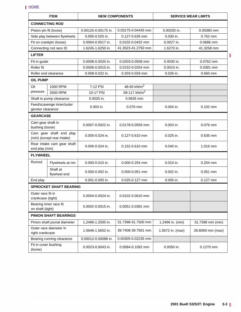
HOME
ITEM NEW COMPONENTS SERVICE WEAR LIMITS
CONNECTING ROD
Piston pin fit (loose) 0.00125-0.00175 in. 0.03175-0.04445 mm 0.00200 in. 0.05080 mm
Side play between flywheels 0.005-0.025 in. 0.127-0.635 mm 0.030 in. 0.762 mm
Fit on crankpin (loose) 0.0004-0.0017 in. 0.0102-0.0432 mm 0.0027 in. 0.0686 mm
Connecting rod race ID 1.6245-1.6250 in. 41.2623-41.2750 mm 1.6270 in. 41.3258 mm
LIFTER
Fit in guide 0.0008-0.0020 in. 0.0203-0.0508 mm 0.0030 in. 0.0762 mm
Roller fit 0.0006-0.0010 in. 0.0152-0.0254 mm 0.0015 in. 0.0381 mm
Roller end clearance 0.008-0.022 in. 0.203-0.559 mm 0.026 in. 0.660 mm
OIL PUMP
Oilpressure
1000 RPM 7-12 PSI 48-83 kN/m2
2500 RPM 10-17 PSI 69-117 kN/m2
Shaft to pump clearance 0.0025 in. 0.0635 mm
Feed/scavenge inner/outergerotor clearance
0.003 in. 0.076 mm 0.004 in. 0.102 mm
GEARCASE
Cam gear shaft in bushing (loose)
0.0007-0.0022 in. 0.0178-0.0559 mm 0.003 in. 0.076 mm
Cam gear shaft end play(min) (except rear intake)
0.005-0.024 in. 0.127-0.610 mm 0.025 in. 0.635 mm
Rear intake cam gear shaftend play (min)
0.006-0.024 in. 0.152-0.610 mm 0.040 in. 1.016 mm
FLYWHEEL
Runout Flywheels at rim 0.000-0.010 in. 0.000-0.254 mm 0.010 in. 0.254 mm
Shaft at flywheel end
0.000-0.002 in. 0.000-0.051 mm 0.002 in. 0.051 mm
End play 0.001-0.005 in. 0.025-0.127 mm 0.005 in. 0.127 mm
SPROCKET SHAFT BEARING
Outer race fit in crankcase (tight)
0.0004-0.0024 in. 0.0102-0.0610 mm
Bearing inner race fit on shaft (tight)
0.0002-0.0015 in. 0.0051-0.0381 mm
PINION SHAFT BEARINGS
Pinion shaft jounal diameter 1.2496-1.2500 in. 31.7398-31.7500 mm 1.2496 in. (min) 31.7398 mm (min)
Outer race diameter in right crankcase
1.5646-1.5652 in. 39.7408-39.7561 mm 1.5672 in. (max) 39.8069 mm (max)
Bearing running clearance 0.00012-0.00088 in. 0.00305-0.02235 mm
Fit in cover bushing(loose)
0.0023-0.0043 in. 0.0584-0.1092 mm 0.0050 in. 0.1270 mm
2001 Buell S3/S3T: Engine 3-3
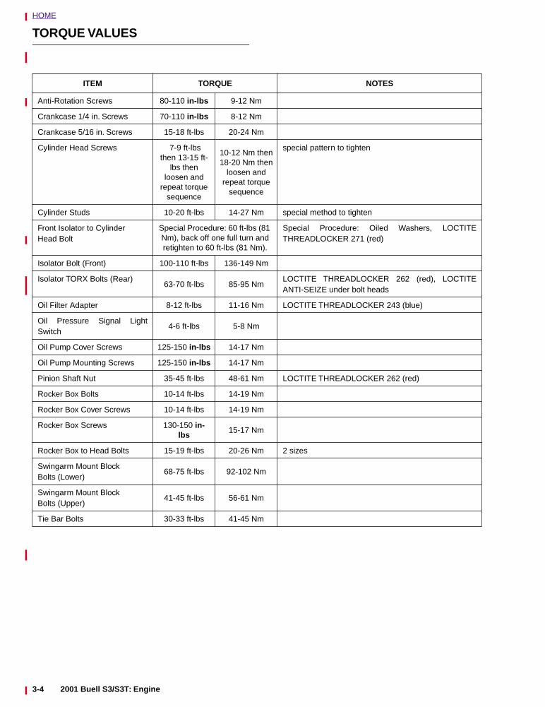
HOME
TORQUE VALUES
ITEM TORQUE NOTES
Anti-Rotation Screws 80-110 in-lbs 9-12 Nm
Crankcase 1/4 in. Screws 70-110 in-lbs 8-12 Nm
Crankcase 5/16 in. Screws 15-18 ft-lbs 20-24 Nm
Cylinder Head Screws 7-9 ft-lbs then 13-15 ft-
lbs then loosen and
repeat torque sequence
10-12 Nm then 18-20 Nm then
loosen and repeat torque
sequence
special pattern to tighten
Cylinder Studs 10-20 ft-lbs 14-27 Nm special method to tighten
Front Isolator to Cylinder Head Bolt
Special Procedure: 60 ft-lbs (81 Nm), back off one full turn and retighten to 60 ft-lbs (81 Nm).
Special Procedure: Oiled Washers, LOCTITETHREADLOCKER 271 (red)
Isolator Bolt (Front) 100-110 ft-lbs 136-149 Nm
Isolator TORX Bolts (Rear)63-70 ft-lbs 85-95 Nm
LOCTITE THREADLOCKER 262 (red), LOCTITEANTI-SEIZE under bolt heads
Oil Filter Adapter 8-12 ft-lbs 11-16 Nm LOCTITE THREADLOCKER 243 (blue)
Oil Pressure Signal LightSwitch
4-6 ft-lbs 5-8 Nm
Oil Pump Cover Screws 125-150 in-lbs 14-17 Nm
Oil Pump Mounting Screws 125-150 in-lbs 14-17 Nm
Pinion Shaft Nut 35-45 ft-lbs 48-61 Nm LOCTITE THREADLOCKER 262 (red)
Rocker Box Bolts 10-14 ft-lbs 14-19 Nm
Rocker Box Cover Screws 10-14 ft-lbs 14-19 Nm
Rocker Box Screws 130-150 in-lbs
15-17 Nm
Rocker Box to Head Bolts 15-19 ft-lbs 20-26 Nm 2 sizes
Swingarm Mount Block Bolts (Lower)
68-75 ft-lbs 92-102 Nm
Swingarm Mount Block Bolts (Upper)
41-45 ft-lbs 56-61 Nm
Tie Bar Bolts 30-33 ft-lbs 41-45 Nm
3-4 2001 Buell S3/S3T: Engine
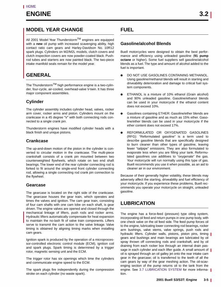
HOME
ENGINE 3.2
MODEL YEAR CHANGE
All 2001 Model Year ThunderstormTM engines are equippedwith a new oil pump with increased scavenging ability, highcontact ratio cam gears and Harley-Davidson No. 10R12spark plugs. Cylinders on M2/M2L models, clutch covers andclutch inspection covers are now powder-coated black. Push-rod tubes and starters are now painted black. The two-pieceintake manifold seals remain for the model year.
GENERAL
The ThunderstormTM high performance engine is a two-cylin-der, four-cycle, air-cooled, overhead-valve V-twin. It has threemajor component assemblies.
Cylinder
The cylinder assembly includes cylinder head, valves, rockerarm cover, rocker arms and piston. Cylinders mount on thecrankcase in a 45 degree “V” with both connecting rods con-nected to a single crank pin.
Thunderstorm engines have modified cylinder heads with ablack finish and unique pistons.
Crankcase
The up-and-down motion of the piston in the cylinder is con-verted to circular motion in the crankcase. The multi-piececrankshaft consists of a crank pin mounted between twocounterweighted flywheels, which rotate on two end shaftbearings. The lower end of the rear cylinder connecting rod isforked to fit around the single-end front cylinder connectingrod, allowing a single connecting rod crank pin connection tothe flywheel.
Gearcase
The gearcase is located on the right side of the crankcase.The gearcase houses the gear train, which operates andtimes the valves and ignition. The cam gear train, consistingof four cam shafts with one cam lobe on each shaft, is geardriven. The engine valves are opened and closed through themechanical linkage of lifters, push rods and rocker arms.Hydraulic lifters automatically compensate for heat expansionto maintain the no-lash fit of valve train components. Liftersserve to transmit the cam action to the valve linkage. Valvetiming is obtained by aligning timing marks when installingcam gears.
Ignition spark is produced by the operation of a microproces-sor-controlled electronic control module (ECM), ignition coiland spark plugs. Spark timing is determined by a triggerrotor, magnetic sensing unit and the ECM.
The trigger rotor has six openings which time the cylindersand communicate engine speed to the ECM.
The spark plugs fire independently during the compressionstroke on each cylinder (no waste spark).
FUEL
Gasoline/alcohol Blends
Buell motorcycles were designed to obtain the best perfor-mance and efficiency using unleaded gasoline (91 pumpoctane or higher). Some fuel suppliers sell gasoline/alcoholblends as a fuel. The type and amount of alcohol added to thefuel is important.
● DO NOT USE GASOLINES CONTAINING METHANOL.Using gasoline/methanol blends will result in starting anddriveability deterioration and damage to critical fuel sys-tem components.
● ETHANOL is a mixture of 10% ethanol (Grain alcohol)and 90% unleaded gasoline. Gasoline/ethanol blendscan be used in your motorcycle if the ethanol contentdoes not exceed 10%.
● Gasolines containing ETHER: Gasoline/ether blends area mixture of gasoline and as much as 15% ether. Gaso-line/ether blends can be used in your motorcycle if theether content does not exceed 17%.
● REFORMULATED OR OXYGENATED GASOLINES(RFG): “Reformulated gasoline” is a term used todescribe gasoline blends that are specifically designedto burn cleaner than other types of gasoline, leavingfewer “tailpipe” emissions. They are also formulated toevaporate less when you are filling your tank. Reformu-lated gasolines use additives to “oxygenate” the gas.Your motorcycle will run normally using this type of gas.Buell recommends you use it when possible, as an aid tocleaner air in our environment.
Because of their generally higher volatility, these blends mayadversely affect the starting, driveability and fuel efficiency ofyour motorcycle. If you experience these problems, Buell rec-ommends you operate your motorcycle on straight, unleadedgasoline.
LUBRICATION
The engine has a force-feed (pressure) type oiling system,incorporating oil feed and return pumps in one pump body, withone check valve on the oil feed side. The feed pump forces oilto the engine, lubricating lower connecting rod bearings, rockerarm bushings, valve stems, valve springs, push rods andhydraulic lifters. Cylinder walls, pistons, piston pins, timinggears and bushings and main bearings are lubricated by oilspray thrown off connecting rods and crankshaft, and by oildraining from each rocker box through an internal drain pas-sage in each cylinder and each lifter guide. A small amount ofoil is sprayed through an oil galley jet onto the rear intake camgear in the gearcase; oil is transferred to the teeth of all thecam gears by way of the gear meshing action. The oil-scav-enging section of the pump returns oil to the tank from theengine. See 3.7 LUBRICATION SYSTEM for more informa-tion.
2001 Buell S3/S3T: Engine 3-5
HOME
ADJUSTMENT/TESTING
GeneralWhen an engine needs repair, it is not always possible todetermine definitely beforehand whether repair is possiblewith only cylinder heads, cylinders and pistons disassembledor whether complete engine disassembly is required forcrankcase repair.
Most commonly, only cylinder head and cylinder repair isneeded (valves, rings, piston, etc.) and it is recommendedprocedure to service these units first, allowing engine crank-case to remain in frame.
See 3.3 STRIPPING MOTORCYCLE FOR ENGINE REPAIRto strip motorcycle for removal of cylinder heads, cylinders,and pistons.
After disassembling “upper end” only, it may be found thatcrankcase repair is necessary. In this situation, remove theengine crankcase from the chassis. See 3.3 STRIPPINGMOTORCYCLE FOR ENGINE REPAIR.
CAUTION
If engine is removed from chassis, do not lay engine onprimary side. Placing engine on primary side will dam-age clutch cable end fitting. If fitting is damaged, clutchcable must be replaced.
Symptoms indicating a need for engine repair are often mis-leading, but generally, if more than one symptom is present,possible causes can be narrowed down to make at least apartial diagnosis. An above-normal consumption of oil, forexample, could be caused by several mechanical faults. See1.22 TROUBLESHOOTING. However, when accompanied byblue-gray exhaust smoke and low engine compression, it indi-cates the piston rings need replacing. Low compression byitself, however, may indicate improperly seated valves, inaddition to or in lieu of worn piston rings.
Most frequently, valves, rings, pins, bushings, and bearingsneed attention at about the same time. If the possible causescan be narrowed down through the process of elimination toindicate any one of the above components is worn, it is bestto give attention to all of the cylinder head and cylinder parts.
Compression Test ProcedureCombustion chamber leakage can result in unsatisfactoryengine performance. A compression test can help determinethe source of cylinder leakage. Use CYLINDER COMPRES-SION GAUGE (Part No. HD-33223-1).
A proper compression test should be performed with theengine at normal operating temperature when possible. Pro-ceed as follows:
CAUTION
After completing the compression test(s), make sure thatthe throttle plate is in the closed position before startingengine. Engine will start at an extremely high RPM ifthrottle plate is left open.
1. Disconnect spark plug wires. Clean around plug baseand remove plugs.
2. Connect compression tester to front cylinder.
3. With carburetor throttle plates in wide open position,crank engine continuously through 5-7 full compressionstrokes.
4. Note gauge readings at the end of the first and last com-pression strokes. Record test results.
5. Connect compression tester to rear cylinder.
6. Repeat Steps 3 and 4 on rear cylinder.
7. Compression is normal if final readings are 120 psi(827 kN/m2) or more and do not indicate more than a 10psi (69 kN/m2) variance between cylinders. See Table 3-1.
8. Inject approximately 1/2 oz. (15 ml) of SAE 30 oil intoeach cylinder and repeat the compression tests on bothcylinders. Readings that are considerably higher duringthe second test indicate worn piston rings.
Table 3-1. Compression Test Results
DIAGNOSIS TEST RESULTS
Ring trouble Compression low on first stroke; tends to build up on the following strokes but does not reach normal; improves considerably when oil is added to cylinder.
Valve trouble Compression low on first stroke; does not build up much on follow-ing strokes; does not improve con-siderably with the addition of oil.
Head gasket leak Same reaction as valve trouble.
3-6 2001 Buell S3/S3T: Engine
HOME
Cylinder Leakage TestThe cylinder leakage test pinpoints engine problems includ-ing leaking valves, worn, broken or stuck piston rings andblown head gaskets. The cylinder leakage tester applies com-pressed air to the cylinder at a controlled pressure and vol-ume, and measures the percent of leakage from the cylinder.
Use a CYLINDER LEAKDOWN TESTER (Part No. HD-35667A) and follow the specific instructions supplied with thetester.
The following are some general instructions that apply toBuell motorcycle engines:
1. Run engine until it reaches normal operating tempera-ture.
2. Stop engine. Clean dirt from around spark plugs andremove spark plugs.
3. Remove air cleaner and set carburetor throttle in wideopen position.
4. Remove timing inspection plug from crankcase.
5. The piston, in cylinder being tested, must be at top deadcenter of compression stroke during test.
6. To keep engine from turning over when air pressure isapplied to cylinder, engage transmission in fifth gear andlock the rear brake.
7. Following the manufacturer’s instructions, perform a cyl-inder leakage test on the front cylinder. Make a note ofthe percent leakdown. Any cylinder with 12% leakdown,or more, requires further attention.
8. Listen for air leaks at carburetor intake, exhaust, headgasket and timing inspection hole. See Table 3-2.
NOTEIf air is escaping through valves, check push rod length.
9. Repeat procedure on rear cylinder.
CAUTION
After completing the compression test(s), make sure thatthe throttle plate is in the closed position before startingengine. Engine will start at an extremely high RPM ifthrottle plate is left open.
Diagnosing Smoking Engine or High Oil Consumption
Perform COMPRESSION TEST PROCEDURE or CYLINDERLEAKAGE TEST as described previously. If further testing isneeded, remove suspect head(s) and inspect the following:
● Valve guide seals.
● Valve guide-to-valve stem clearance.
● Gasket surface of both head and cylinder.
● Oil return passages for clogging.
Table 3-2. Air Leakage Test
AIR LEAK LOCATION POSSIBLE CAUSES
Intake Manifold Intake valve leaking.
Exhaust Pipe Exhaust valve leaking.
Timing Inspection Hole Piston rings leaking.Worn or broken piston.Worn cylinder.
Head Gasket Leaking gasket.
2001 Buell S3/S3T: Engine 3-7
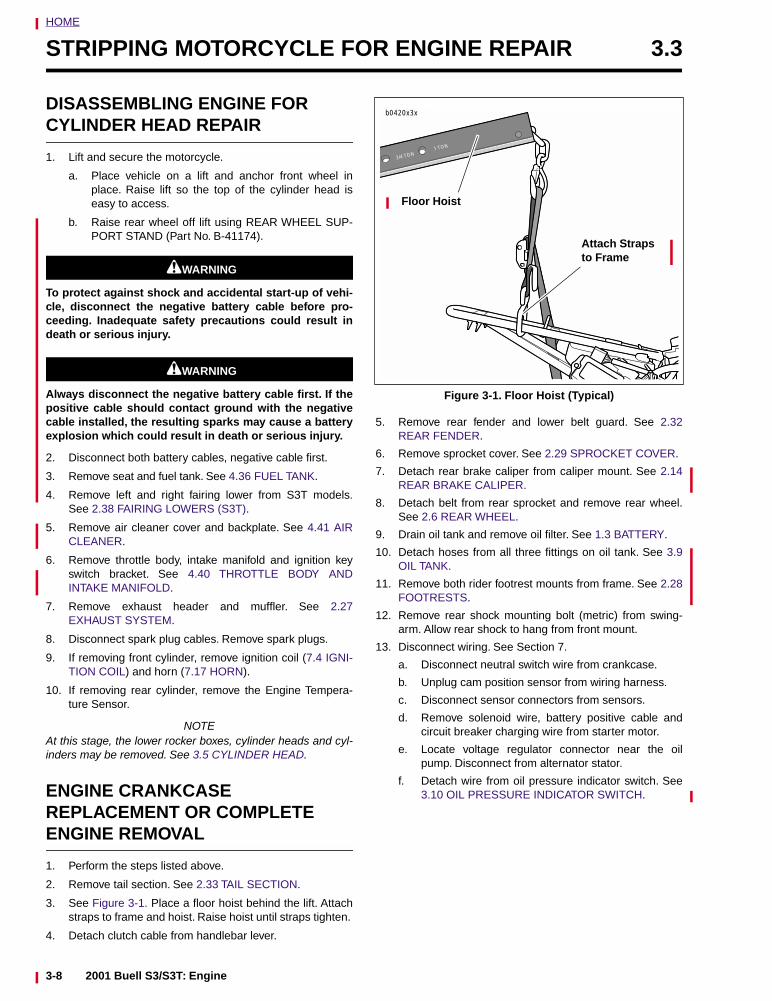
HOME
STRIPPING MOTORCYCLE FOR ENGINE REPAIR 3.3
DISASSEMBLING ENGINE FOR CYLINDER HEAD REPAIR
1. Lift and secure the motorcycle.
a. Place vehicle on a lift and anchor front wheel inplace. Raise lift so the top of the cylinder head iseasy to access.
b. Raise rear wheel off lift using REAR WHEEL SUP-PORT STAND (Part No. B-41174).
11WARNING1WARNING
To protect against shock and accidental start-up of vehi-cle, disconnect the negative battery cable before pro-ceeding. Inadequate safety precautions could result indeath or serious injury.
11WARNING1WARNING
Always disconnect the negative battery cable first. If thepositive cable should contact ground with the negativecable installed, the resulting sparks may cause a batteryexplosion which could result in death or serious injury.
2. Disconnect both battery cables, negative cable first.
3. Remove seat and fuel tank. See 4.36 FUEL TANK.
4. Remove left and right fairing lower from S3T models.See 2.38 FAIRING LOWERS (S3T).
5. Remove air cleaner cover and backplate. See 4.41 AIRCLEANER.
6. Remove throttle body, intake manifold and ignition keyswitch bracket. See 4.40 THROTTLE BODY ANDINTAKE MANIFOLD.
7. Remove exhaust header and muffler. See 2.27EXHAUST SYSTEM.
8. Disconnect spark plug cables. Remove spark plugs.
9. If removing front cylinder, remove ignition coil (7.4 IGNI-TION COIL) and horn (7.17 HORN).
10. If removing rear cylinder, remove the Engine Tempera-ture Sensor.
NOTEAt this stage, the lower rocker boxes, cylinder heads and cyl-inders may be removed. See 3.5 CYLINDER HEAD.
ENGINE CRANKCASE REPLACEMENT OR COMPLETE ENGINE REMOVAL
1. Perform the steps listed above.
2. Remove tail section. See 2.33 TAIL SECTION.
3. See Figure 3-1. Place a floor hoist behind the lift. Attachstraps to frame and hoist. Raise hoist until straps tighten.
4. Detach clutch cable from handlebar lever.
5. Remove rear fender and lower belt guard. See 2.32REAR FENDER.
6. Remove sprocket cover. See 2.29 SPROCKET COVER.
7. Detach rear brake caliper from caliper mount. See 2.14REAR BRAKE CALIPER.
8. Detach belt from rear sprocket and remove rear wheel.See 2.6 REAR WHEEL.
9. Drain oil tank and remove oil filter. See 1.3 BATTERY.
10. Detach hoses from all three fittings on oil tank. See 3.9OIL TANK.
11. Remove both rider footrest mounts from frame. See 2.28FOOTRESTS.
12. Remove rear shock mounting bolt (metric) from swing-arm. Allow rear shock to hang from front mount.
13. Disconnect wiring. See Section 7.
a. Disconnect neutral switch wire from crankcase.
b. Unplug cam position sensor from wiring harness.
c. Disconnect sensor connectors from sensors.
d. Remove solenoid wire, battery positive cable andcircuit breaker charging wire from starter motor.
e. Locate voltage regulator connector near the oilpump. Disconnect from alternator stator.
f. Detach wire from oil pressure indicator switch. See3.10 OIL PRESSURE INDICATOR SWITCH.
Figure 3-1. Floor Hoist (Typical)
3/4 TON1 TON
Attach Straps to Frame
b0420x3x
Floor Hoist
3-8 2001 Buell S3/S3T: Engine
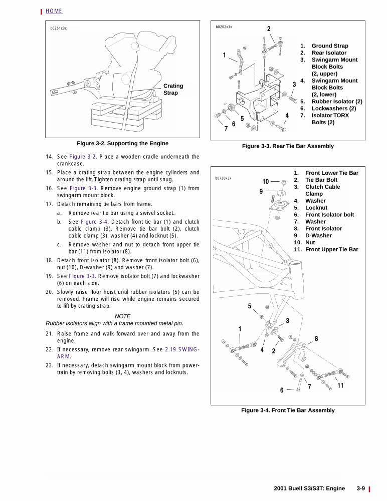
HOME
14. See Figure 3-2. Place a wooden cradle underneath thecrankcase.
15. Place a crating strap between the engine cylinders andaround the lift. Tighten crating strap until snug.
16. See Figure 3-3. Remove engine ground strap (1) fromswingarm mount block.
17. Detach remaining tie bars from frame.
a. Remove rear tie bar using a swivel socket.
b. See Figure 3-4. Detach front tie bar (1) and clutchcable clamp (3). Remove tie bar bolt (2), clutchcable clamp (3), washer (4) and locknut (5).
c. Remove washer and nut to detach front upper tiebar (11) from isolator (8).
18. Detach front isolator (8). Remove front isolator bolt (6),nut (10), D-washer (9) and washer (7).
19. See Figure 3-3. Remove isolator bolt (7) and lockwasher(6) on each side.
20. Slowly raise floor hoist until rubber isolators (5) can beremoved. Frame will rise while engine remains securedto lift by crating strap.
NOTERubber isolators align with a frame mounted metal pin.
21. Raise frame and walk forward over and away from theengine.
22. If necessary, remove rear swingarm. See 2.19 SWING-ARM.
23. If necessary, detach swingarm mount block from power-train by removing bolts (3, 4), washers and locknuts.
Figure 3-2. Supporting the Engine
b0251x3x
Crating Strap
Figure 3-3. Rear Tie Bar Assembly
Figure 3-4. Front Tie Bar Assembly
1. Ground Strap2. Rear Isolator3. Swingarm Mount
Block Bolts (2, upper)
4. Swingarm Mount Block Bolts (2, lower)
5. Rubber Isolator (2)6. Lockwashers (2)7. Isolator TORX
Bolts (2)
b0202x3x 2
1
75
3
46
b0730x3x1. Front Lower Tie Bar2. Tie Bar Bolt3. Clutch Cable
Clamp4. Washer5. Locknut6. Front Isolator bolt7. Washer8. Front Isolator9. D-Washer10. Nut11. Front Upper Tie Bar
1
6 7
910
24
5
3
8
11
2001 Buell S3/S3T: Engine 3-9
HOME
INSTALLING THE ENGINE 3.4
ENGINE CRANKCASE INSTALLATION
1. See Figure 3-2. Place engine crankcase on supports soframe may be installed over the top of the engine.
2. See Figure 3-3. If removed, attach swingarm mountblock to engine. Install upper bolts (3), washers and lock-nuts finger tight. Install lower bolts (4), washers and lock-nuts finger tight. Tighten upper bolts to 41-45 ft-lbs (56-61 Nm) and lower bolts to 68-75 ft-lbs (92-102 Nm).
3. If removed, install swingarm. Adjust swingarm bearingpreload. See 2.19 SWINGARM.
4. If removed, install transmission mainshaft sprocket. See6.13 TRANSMISSION INSTALLATION AND SHIFTERPAWL ADJUSTMENT.
5. Remove oil filter (if installed). Walk frame over powertrain.
6. See Figure 3-4. Attach front isolator (8). Install front iso-lator mount with bolt (6), washers (7), D-washer (9) andlocknut (10). Flat on D-washer faces steering neck (for-ward). Tighten bolt finger tight.
7. Install rear isolators but do not tighten isolator bolts atthis time. See 2.20 REAR ISOLATORS.
CAUTION
Do not adjust tie bar assemblies. Tie bar tension is set atthe factory. Any attempt at adjusting tension will causedamage to tie bars. Damaged tie bars must be replaced.
8. See Figure 3-3. Rear tie bar must be horizontal andbelow frame tab. Insert bolt upwards through washer, tiebar and frame. Fasten with nut. Tighten bolt to 30-33 ft-lbs (41-45 Nm).
9. See Figure 3-4. Place clutch cable clamp (3) on front tiebar bolt (2). Clamp should hold cable on primary coverside of motor. Insert bolt from front through frame andinstall washer (4). Continue through tie bar (1) andframe. Install locknut (5) and tighten to 30-33 ft-lbs (41-45 Nm).
10. Attach front upper tie bar (11). Insert bolt through tie barfront isolator, and frame. Secure with nut and washer.Tighten to 30-33 ft-lbs (41-45 Nm).
11. See Figure 3-3. Tighten the two rear isolator TORX boltsto 63-70 ft-lbs (85-95 Nm)
12. See Figure 3-4. Tighten front isolator bolt (6) to 100-110ft-lbs (136-149 Nm).
13. Connect feed, return and vent lines to oil tank. See 3.8OIL HOSE ROUTING. Use new hose clamps.
14. Attach battery ground strap to swingarm mount block.
15. Attach clutch cable to handlebar lever.
16. Remove strap from between engine cylinders. Using afloor hoist, lift motorcycle by the frame and remove thewooden cradle from underneath the crankcase.
17. Install rear shock. See 2.21 REAR SHOCK ABSORBER.Remove floor hoist straps.
18. Install rear wheel and attach drive belt. See 2.6 REARWHEEL.
19. Install rear brake caliper. See 2.14 REAR BRAKE CALI-PER.
20. Attach disconnected wires. See Section 7.
a. Connect solenoid wire, circuit breaker charging wireand battery positive cable to starter.
b. Connect voltage regulator connector to alternatorstator wiring.
c. Attach cam position sensor to wire harness.
d. Connect neutral switch wire to crankcase.
e. Attach oil pressure indicator switch wire.
21. Install rear fender and lower belt guard. See 2.32 REARFENDER.
22. Install sprocket cover. See 2.29 SPROCKET COVER.
23. Install footrests. See 2.28 FOOTRESTS.
24. Continue with the steps listed under ENGINE INSTAL-LATION AFTER CYLINDER HEAD REPAIR.
ENGINE INSTALLATION AFTER CYLINDER HEAD REPAIR
1. Install new oil filter, engine oil and primary chaincasefluid as necessary. See Section 1.
2. Install intake manifold, throttle body and ignition keyswitch bracket. See 4.40 THROTTLE BODY ANDINTAKE MANIFOLD.
a. Plug ignition key switch connector into main wiringharness.
b. Connect sensor connectors to sensors.
3. Install exhaust system. See 2.27 EXHAUST SYSTEM.
4. Install air cleaner assembly. See 4.41 AIR CLEANER.
5. If removed, install horn (7.17 HORN) and ignition coil(7.4 IGNITION COIL).
6. Install spark plugs and connect cables. See 1.16 SPARKPLUGS.
3-10 2001 Buell S3/S3T: Engine
HOME
11WARNING1WARNING
Always connect positive battery cable first. If the positivecable should contact ground with the negative cableinstalled, the resulting sparks may cause a battery explo-sion which could result in death or serious injury.
7. Install battery. Connect battery cables, positive cablefirst.
8. Install left and right fairing lowers on S3T models. See2.38 FAIRING LOWERS (S3T).
9. Install tail section, fuel tank and seat. See 2.33 TAILSECTION.
10. If engine crankcase installation was performed:
a. Adjust rear belt deflection. See 1.9 DRIVE BELTDEFLECTION.
b. Adjust rear shock spring preload. See 1.12 PRE-LOAD ADJUSTMENT.
c. Adjust clutch lever. See 1.8 CLUTCH.
d. Check rear brake pedal height. See 1.5 BRAKES.
11. Check all electrical components for proper operation.
2001 Buell S3/S3T: Engine 3-11
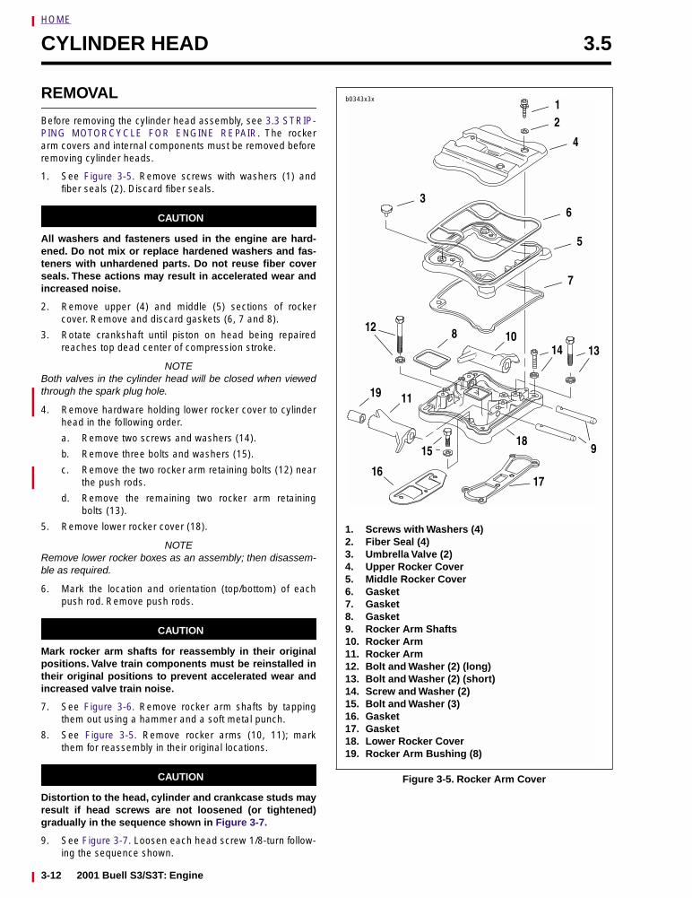
HOME
CYLINDER HEAD 3.5
REMOVAL
Before removing the cylinder head assembly, see 3.3 STRIP-PING MOTORCYCLE FOR ENGINE REPAIR. The rockerarm covers and internal components must be removed beforeremoving cylinder heads.
1. See Figure 3-5. Remove screws with washers (1) andfiber seals (2). Discard fiber seals.
CAUTION
All washers and fasteners used in the engine are hard-ened. Do not mix or replace hardened washers and fas-teners with unhardened parts. Do not reuse fiber coverseals. These actions may result in accelerated wear andincreased noise.
2. Remove upper (4) and middle (5) sections of rockercover. Remove and discard gaskets (6, 7 and 8).
3. Rotate crankshaft until piston on head being repairedreaches top dead center of compression stroke.
NOTEBoth valves in the cylinder head will be closed when viewedthrough the spark plug hole.
4. Remove hardware holding lower rocker cover to cylinderhead in the following order.
a. Remove two screws and washers (14).
b. Remove three bolts and washers (15).
c. Remove the two rocker arm retaining bolts (12) nearthe push rods.
d. Remove the remaining two rocker arm retainingbolts (13).
5. Remove lower rocker cover (18).
NOTERemove lower rocker boxes as an assembly; then disassem-ble as required.
6. Mark the location and orientation (top/bottom) of eachpush rod. Remove push rods.
CAUTION
Mark rocker arm shafts for reassembly in their originalpositions. Valve train components must be reinstalled intheir original positions to prevent accelerated wear andincreased valve train noise.
7. See Figure 3-6. Remove rocker arm shafts by tappingthem out using a hammer and a soft metal punch.
8. See Figure 3-5. Remove rocker arms (10, 11); markthem for reassembly in their original locations.
CAUTION
Distortion to the head, cylinder and crankcase studs mayresult if head screws are not loosened (or tightened)gradually in the sequence shown in Figure 3-7.
9. See Figure 3-7. Loosen each head screw 1/8-turn follow-ing the sequence shown.
Figure 3-5. Rocker Arm Cover
1. Screws with Washers (4)2. Fiber Seal (4)3. Umbrella Valve (2)4. Upper Rocker Cover5. Middle Rocker Cover6. Gasket7. Gasket8. Gasket9. Rocker Arm Shafts10. Rocker Arm11. Rocker Arm12. Bolt and Washer (2) (long)13. Bolt and Washer (2) (short)14. Screw and Washer (2)15. Bolt and Washer (3)16. Gasket17. Gasket18. Lower Rocker Cover19. Rocker Arm Bushing (8)
b0343x3x12
4
6
5
7
3
1314
19 11
8 10
1617
1518
9
12
3-12 2001 Buell S3/S3T: Engine
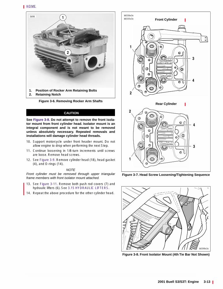
HOME
CAUTION
See Figure 3-8. Do not attempt to remove the front isola-tor mount from front cylinder head. Isolator mount is anintegral component and is not meant to be removedunless absolutely necessary. Repeated removals andinstallations will damage cylinder head threads.
10. Support motorcycle under front header mount. Do notallow engine to drop when performing the next Step.
11. Continue loosening in 1/8-turn increments until screwsare loose. Remove head screws.
12. See Figure 3-9. Remove cylinder head (18), head gasket(4), and O-rings (14).
NOTEFront cylinder must be removed through upper triangularframe members with front isolator mount attached.
13. See Figure 3-11. Remove both push rod covers (7) andhydraulic lifters (6). See 3.15 HYDRAULIC LIFTERS.
14. Repeat the above procedure for the other cylinder head.
Figure 3-6. Removing Rocker Arm Shafts
5698
2
1. Position of Rocker Arm Retaining Bolts2. Retaining Notch
1
Figure 3-7. Head Screw Loosening/Tightening Sequence
Figure 3-8. Front Isolator Mount (4th Tie Bar Not Shown)
b0336x3x
2
b0335x3x
2
3
4
1
4
3
Front Cylinder
Rear Cylinder
1
b0390x3x
2001 Buell S3/S3T: Engine 3-13
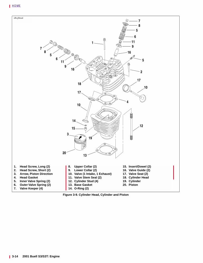
HOME
Figure 3-9. Cylinder Head, Cylinder and Piston
18
78
56
119
16
17
10
14
2
10
12
4
13
193
15
17
85
7
1
16
5
6119
20
1. Head Screw, Long (2)2. Head Screw, Short (2)3. Arrow, Piston Direction4. Head Gasket5. Inner Valve Spring (2)6. Outer Valve Spring (2)7. Valve Keeper (4)
8. Upper Collar (2)9. Lower Collar (2)10. Valve (1 Intake, 1 Exhaust)11. Valve Stem Seal (2)12. Cylinder Stud (4)13. Base Gasket14. O-Ring (2)
15. Insert/Dowel (2)16. Valve Guide (2)17. Valve Seat (2)18. Cylinder Head19. Cylinder20. Piston
xlhcylhead
3-14 2001 Buell S3/S3T: Engine
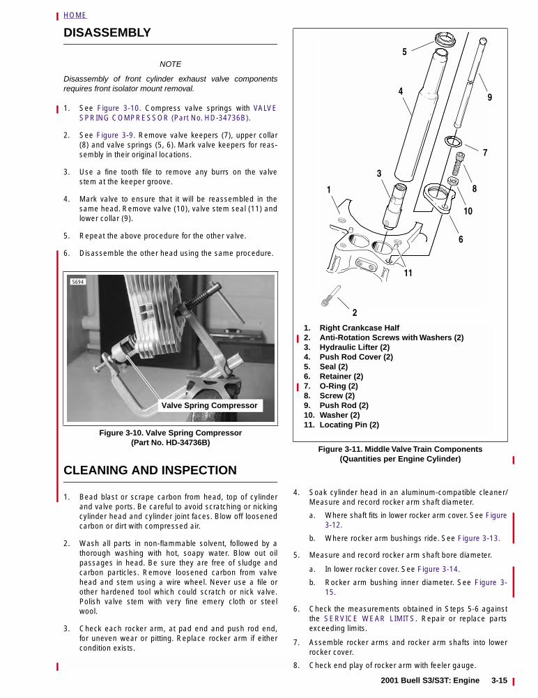
HOME
DISASSEMBLY
NOTE
Disassembly of front cylinder exhaust valve componentsrequires front isolator mount removal.
1. See Figure 3-10. Compress valve springs with VALVESPRING COMPRESSOR (Part No. HD-34736B).
2. See Figure 3-9. Remove valve keepers (7), upper collar(8) and valve springs (5, 6). Mark valve keepers for reas-sembly in their original locations.
3. Use a fine tooth file to remove any burrs on the valvestem at the keeper groove.
4. Mark valve to ensure that it will be reassembled in thesame head. Remove valve (10), valve stem seal (11) andlower collar (9).
5. Repeat the above procedure for the other valve.
6. Disassemble the other head using the same procedure.
CLEANING AND INSPECTION
1. Bead blast or scrape carbon from head, top of cylinderand valve ports. Be careful to avoid scratching or nickingcylinder head and cylinder joint faces. Blow off loosenedcarbon or dirt with compressed air.
2. Wash all parts in non-flammable solvent, followed by athorough washing with hot, soapy water. Blow out oilpassages in head. Be sure they are free of sludge andcarbon particles. Remove loosened carbon from valvehead and stem using a wire wheel. Never use a file orother hardened tool which could scratch or nick valve.Polish valve stem with very fine emery cloth or steelwool.
3. Check each rocker arm, at pad end and push rod end,for uneven wear or pitting. Replace rocker arm if eithercondition exists.
4. Soak cylinder head in an aluminum-compatible cleaner/Measure and record rocker arm shaft diameter.
a. Where shaft fits in lower rocker arm cover. See Figure3-12.
b. Where rocker arm bushings ride. See Figure 3-13.
5. Measure and record rocker arm shaft bore diameter.
a. In lower rocker cover. See Figure 3-14.
b. Rocker arm bushing inner diameter. See Figure 3-15.
6. Check the measurements obtained in Steps 5-6 againstthe SERVICE WEAR LIMITS. Repair or replace partsexceeding limits.
7. Assemble rocker arms and rocker arm shafts into lowerrocker cover.
8. Check end play of rocker arm with feeler gauge.
Figure 3-10. Valve Spring Compressor (Part No. HD-34736B)
5694
Valve Spring Compressor
Figure 3-11. Middle Valve Train Components(Quantities per Engine Cylinder)
1. Right Crankcase Half2. Anti-Rotation Screws with Washers (2)3. Hydraulic Lifter (2)4. Push Rod Cover (2)5. Seal (2)6. Retainer (2)7. O-Ring (2)8. Screw (2)9. Push Rod (2)10. Washer (2)11. Locating Pin (2)
3
4
1
2
6
10
11
8
5
9
7
2001 Buell S3/S3T: Engine 3-15
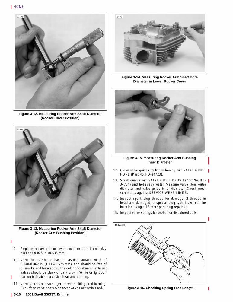
HOME
9. Replace rocker arm or lower cover or both if end playexceeds 0.025 in. (0.635 mm).
10. Valve heads should have a seating surface width of0.040-0.062 in. (1.016-1.575 mm), and should be free ofpit marks and burn spots. The color of carbon on exhaustvalves should be black or dark brown. White or light buffcarbon indicates excessive heat and burning.
11. Valve seats are also subject to wear, pitting, and burning.Resurface valve seats whenever valves are refinished.
12. Clean valve guides by lightly honing with VALVE GUIDEHONE (Part No. HD-34723).
13. Scrub guides with VALVE GUIDE BRUSH (Part No. HD-34751) and hot soapy water. Measure valve stem outerdiameter and valve guide inner diameter. Check mea-surements against SERVICE WEAR LIMITS.
14. Inspect spark plug threads for damage. If threads inhead are damaged, a special plug type insert can beinstalled using a 12 mm spark plug repair kit.
15. Inspect valve springs for broken or discolored coils.
Figure 3-12. Measuring Rocker Arm Shaft Diameter(Rocker Cover Position)
Figure 3-13. Measuring Rocker Arm Shaft Diameter(Rocker Arm Bushing Position)
2767a
2768a
Figure 3-14. Measuring Rocker Arm Shaft BoreDiameter in Lower Rocker Cover
Figure 3-15. Measuring Rocker Arm BushingInner Diameter
Figure 3-16. Checking Spring Free Length
5699
b0323x3x
3-16 2001 Buell S3/S3T: Engine
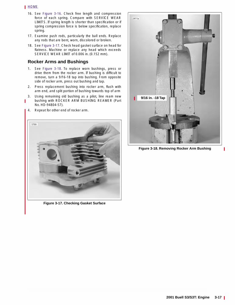
HOME
16. See Figure 3-16. Check free length and compressionforce of each spring. Compare with SERVICE WEARLIMITS. If spring length is shorter than specification or ifspring compression force is below specification, replacespring.
17. Examine push rods, particularly the ball ends. Replaceany rods that are bent, worn, discolored or broken.
18. See Figure 3-17. Check head gasket surface on head forflatness. Machine or replace any head which exceedsSERVICE WEAR LIMIT of 0.006 in. (0.152 mm).
Rocker Arms and Bushings1. See Figure 3-18. To replace worn bushings, press or
drive them from the rocker arm. If bushing is difficult toremove, turn a 9/16-18 tap into bushing. From oppositeside of rocker arm, press out bushing and tap.
2. Press replacement bushing into rocker arm, flush witharm end, and split portion of bushing towards top of arm
3. Using remaining old bushing as a pilot, line ream newbushing with ROCKER ARM BUSHING REAMER (PartNo. HD-94804-57).
4. Repeat for other end of rocker arm.
Figure 3-17. Checking Gasket Surface
5700
Figure 3-18. Removing Rocker Arm Bushing
9/16 in. -18 Tap
2411a
2001 Buell S3/S3T: Engine 3-17
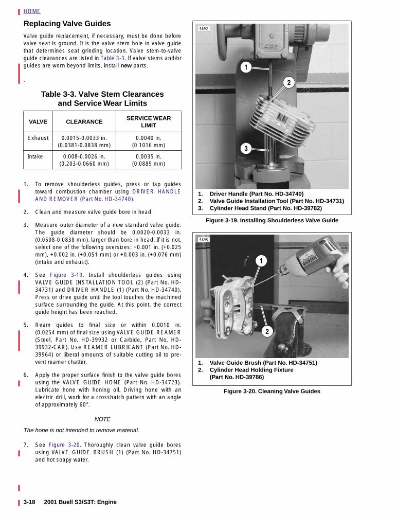
HOME
Replacing Valve Guides
Valve guide replacement, if necessary, must be done beforevalve seat is ground. It is the valve stem hole in valve guidethat determines seat grinding location. Valve stem-to-valveguide clearances are listed in Table 3-3. If valve stems and/orguides are worn beyond limits, install new parts.
.
1. To remove shoulderless guides, press or tap guidestoward combustion chamber using DRIVER HANDLEAND REMOVER (Part No. HD-34740).
2. Clean and measure valve guide bore in head.
3. Measure outer diameter of a new standard valve guide.The guide diameter should be 0.0020-0.0033 in.(0.0508-0.0838 mm). larger than bore in head. If it is not,select one of the following oversizes: +0.001 in. (+0.025mm), +0.002 in. (+0.051 mm) or +0.003 in. (+0.076 mm)(intake and exhaust).
4. See Figure 3-19. Install shoulderless guides usingVALVE GUIDE INSTALLATION TOOL (2) (Part No. HD-34731) and DRIVER HANDLE (1) (Part No. HD-34740).Press or drive guide until the tool touches the machinedsurface surrounding the guide. At this point, the correctguide height has been reached.
5. Ream guides to final size or within 0.0010 in.(0.0254 mm) of final size using VALVE GUIDE REAMER(Steel, Part No. HD-39932 or Carbide, Part No. HD-39932-CAR). Use REAMER LUBRICANT (Part No. HD-39964) or liberal amounts of suitable cutting oil to pre-vent reamer chatter.
6. Apply the proper surface finish to the valve guide boresusing the VALVE GUIDE HONE (Part No. HD-34723).Lubricate hone with honing oil. Driving hone with anelectric drill, work for a crosshatch pattern with an angleof approximately 60°.
NOTE
The hone is not intended to remove material.
7. See Figure 3-20. Thoroughly clean valve guide boresusing VALVE GUIDE BRUSH (1) (Part No. HD-34751)and hot soapy water.
Table 3-3. Valve Stem Clearancesand Service Wear Limits
VALVE CLEARANCESERVICE WEAR
LIMIT
Exhaust 0.0015-0.0033 in.(0.0381-0.0838 mm)
0.0040 in.(0.1016 mm)
Intake 0.008-0.0026 in.(0.203-0.0660 mm)
0.0035 in.(0.0889 mm)
Figure 3-19. Installing Shoulderless Valve Guide
Figure 3-20. Cleaning Valve Guides
5692
1. Driver Handle (Part No. HD-34740)2. Valve Guide Installation Tool (Part No. HD-34731)3. Cylinder Head Stand (Part No. HD-39782)
1
2
3
5695
1. Valve Guide Brush (Part No. HD-34751)2. Cylinder Head Holding Fixture
(Part No. HD-39786)
1
2
3-18 2001 Buell S3/S3T: Engine
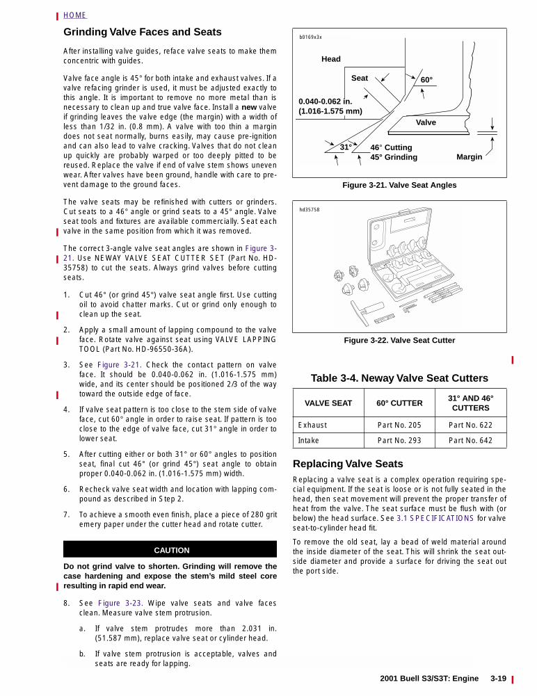
HOME
Grinding Valve Faces and Seats
After installing valve guides, reface valve seats to make themconcentric with guides.
Valve face angle is 45° for both intake and exhaust valves. If avalve refacing grinder is used, it must be adjusted exactly tothis angle. It is important to remove no more metal than isnecessary to clean up and true valve face. Install a new valveif grinding leaves the valve edge (the margin) with a width ofless than 1/32 in. (0.8 mm). A valve with too thin a margindoes not seat normally, burns easily, may cause pre-ignitionand can also lead to valve cracking. Valves that do not cleanup quickly are probably warped or too deeply pitted to bereused. Replace the valve if end of valve stem shows unevenwear. After valves have been ground, handle with care to pre-vent damage to the ground faces.
The valve seats may be refinished with cutters or grinders.Cut seats to a 46° angle or grind seats to a 45° angle. Valveseat tools and fixtures are available commercially. Seat eachvalve in the same position from which it was removed.
The correct 3-angle valve seat angles are shown in Figure 3-21. Use NEWAY VALVE SEAT CUTTER SET (Part No. HD-35758) to cut the seats. Always grind valves before cuttingseats.
1. Cut 46° (or grind 45°) valve seat angle first. Use cuttingoil to avoid chatter marks. Cut or grind only enough toclean up the seat.
2. Apply a small amount of lapping compound to the valveface. Rotate valve against seat using VALVE LAPPINGTOOL (Part No. HD-96550-36A).
3. See Figure 3-21. Check the contact pattern on valveface. It should be 0.040-0.062 in. (1.016-1.575 mm)wide, and its center should be positioned 2/3 of the waytoward the outside edge of face.
4. If valve seat pattern is too close to the stem side of valveface, cut 60° angle in order to raise seat. If pattern is tooclose to the edge of valve face, cut 31° angle in order tolower seat.
5. After cutting either or both 31° or 60° angles to positionseat, final cut 46° (or grind 45°) seat angle to obtainproper 0.040-0.062 in. (1.016-1.575 mm) width.
6. Recheck valve seat width and location with lapping com-pound as described in Step 2.
7. To achieve a smooth even finish, place a piece of 280 gritemery paper under the cutter head and rotate cutter.
CAUTION
Do not grind valve to shorten. Grinding will remove thecase hardening and expose the stem’s mild steel coreresulting in rapid end wear.
8. See Figure 3-23. Wipe valve seats and valve facesclean. Measure valve stem protrusion.
a. If valve stem protrudes more than 2.031 in.(51.587 mm), replace valve seat or cylinder head.
b. If valve stem protrusion is acceptable, valves andseats are ready for lapping.
Replacing Valve SeatsReplacing a valve seat is a complex operation requiring spe-cial equipment. If the seat is loose or is not fully seated in thehead, then seat movement will prevent the proper transfer ofheat from the valve. The seat surface must be flush with (orbelow) the head surface. See 3.1 SPECIFICATIONS for valveseat-to-cylinder head fit.
To remove the old seat, lay a bead of weld material aroundthe inside diameter of the seat. This will shrink the seat out-side diameter and provide a surface for driving the seat outthe port side.
Figure 3-21. Valve Seat Angles
Figure 3-22. Valve Seat Cutter
Table 3-4. Neway Valve Seat Cutters
VALVE SEAT 60° CUTTER31° AND 46° CUTTERS
Exhaust Part No. 205 Part No. 622
Intake Part No. 293 Part No. 642
Head
Valve
46° Cutting45° Grinding
Seat
31°
0.040-0.062 in.(1.016-1.575 mm)
60°
Margin
b0169x3x
hd35758
2001 Buell S3/S3T: Engine 3-19
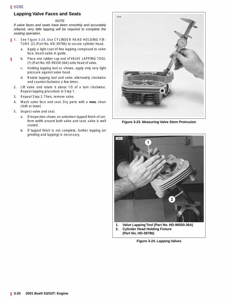
HOME
Lapping Valve Faces and SeatsNOTE
If valve faces and seats have been smoothly and accuratelyrefaced, very little lapping will be required to complete theseating operation.
1. See Figure 3-24. Use CYLINDER HEAD HOLDING FIX-TURE (2) (Part No. HD-39786) to secure cylinder head.
a. Apply a light coat of fine lapping compound to valveface. Insert valve in guide.
b. Place one rubber cup end of VALVE LAPPING TOOL(1) (Part No. HD-96550-36A) onto head of valve.
c. Holding lapping tool as shown, apply only very lightpressure against valve head.
d. Rotate lapping tool and valve alternately clockwiseand counterclockwise a few times.
2. Lift valve and rotate it about 1/3 of a turn clockwise.Repeat lapping procedure in Step 1.
3. Repeat Step 2. Then, remove valve.
4. Wash valve face and seat. Dry parts with a new, cleancloth or towel.
5. Inspect valve and seat.
a. If inspection shows an unbroken lapped finish of uni-form width around both valve and seat, valve is wellseated.
b. If lapped finish is not complete, further lapping (orgrinding and lapping) is necessary.
Figure 3-23. Measuring Valve Stem Protrusion
Figure 3-24. Lapping Valves
5696
5693
1. Valve Lapping Tool (Part No. HD-96550-36A)2. Cylinder Head Holding Fixture
(Part No. HD-39786)
1
2
3-20 2001 Buell S3/S3T: Engine
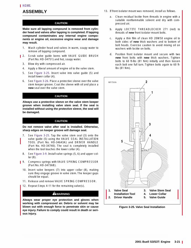
HOME
ASSEMBLY
CAUTION
Make sure all lapping compound is removed from cylin-der head and valves after lapping is completed. If lappingcompound contaminates any internal engine compo-nents or engine oil, excessive engine wear and damagemay result.
1. Wash cylinder head and valves in warm, soapy water toremove all lapping compound.
2. Scrub valve guide bores with VALVE GUIDE BRUSH(Part No. HD-34751) and hot, soapy water.
3. Blow dry with compressed air.
4. Apply a liberal amount of engine oil to the valve stem.
5. See Figure 3-25. Insert valve into valve guide (5) andinstall lower collar (4).
6. See Figure 3-26. Place a protective sleeve over the valvestem keeper groove. Coat the sleeve with oil and place anew seal over the valve stem.
CAUTION
Always use a protective sleeve on the valve stem keepergroove when installing valve stem seal. If the seal isinstalled without using the protective sleeve, the seal willbe damaged.
CAUTION
Do not remove valve after seal is installed. Otherwise,sharp edges on keeper groove will damage seal.
7. See Figure 3-25. Tap the valve stem seal (3) onto thevalve guide (5) using the VALVE SEAL INSTALLATIONTOOL (Part No. HD-34643A) and DRIVER HANDLE(Part No. HD-34740). The seal is completely installedwhen the tool touches the lower collar (4).
8. See Figure 3-9. Install valve springs (5, 6) and upper col-lar (8).
9. Compress springs with VALVE SPRING COMPRESSOR(Part No. HD-34736B).
10. Insert valve keepers (7) into upper collar (8), makingsure they engage groove in valve stem. The keeper gapsshould be equal.
11. Release and remove VALVE SPRING COMPRESSOR.
12. Repeat Steps 4-11 for the remaining valve(s).
11WARNING1WARNING
Always wear proper eye protection and gloves whenworking with compressed air. Debris or solvent may beblown out with enough force to penetrate skin or causeeye injury. Failure to comply could result in death or seri-ous injury.
13. If front isolator mount was removed, install as follows.
a. Clean residual loctite from threads in engine with asuitable nonflammable solvent and dry with com-pressed air.
b. Apply LOCTITE THREADLOCKER 271 (red) tothreads of new front isolator mount bolts.
c. Apply a thin film of clean HD 20W50 engine oil toboth sides of new thick washers and to bottom ofbolt heads. Exercise caution to avoid mixing oil onwashers with loctite on bolts.
d. Position front isolator mount and secure with twonew front bolts with new thick washers. Tightenbolts to 60 ft-lbs (81 Nm) initially and then looseneach bolt one full turn. Tighten bolts again to 60 ft-lbs (81 Nm).
Figure 3-25. Valve Seal Installation
1. Valve SealInstallation Tool
2. Driver Handle
3. Valve Stem Seal4. Lower Collar5. Valve Guide
b0172x3x
1
2
3
4
5
2001 Buell S3/S3T: Engine 3-21
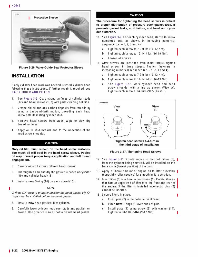
HOME
INSTALLATION
If only cylinder head work was needed, reinstall cylinder headfollowing these instructions. If further repair is required, see3.6 CYLINDER AND PISTON.
1. See Figure 3-9. Coat mating surfaces of cylinder studs(12) and head screws (1, 2) with parts cleaning solution.
2. Scrape old oil and any carbon deposits from threads byusing a back-and-forth motion, threading each headscrew onto its mating cylinder stud.
3. Remove head screws from studs. Wipe or blow drythread surfaces.
4. Apply oil to stud threads and to the underside of thehead screw shoulder.
CAUTION
Only oil film must remain on the head screw surfaces.Too much oil will pool in the head screw sleeve. Pooledoil may prevent proper torque application and full threadengagement.
5. Blow or wipe off excess oil from head screws.
6. Thoroughly clean and dry the gasket surfaces of cylinder(19) and cylinder head (18).
7. Install a new O-ring (14) on each dowel (15).
NOTE
O-rings (14) help to properly position the head gasket (4). O-rings must be installed before the head gasket.
8. Install a new head gasket (4) to cylinder.
9. Carefully lower cylinder head over studs and position ondowels. Use great care so as not to disturb head gasket.
CAUTION
The procedure for tightening the head screws is criticalto proper distribution of pressure over gasket area. Itprevents gasket leaks, stud failure, and head and cylin-der distortion.
10. See Figure 3-7. For each cylinder head, start with screwnumbered one, as shown. In increasing numericalsequence (i.e. – 1, 2, 3 and 4):
a. Tighten each screw to 7-9 ft-lbs (10-12 Nm).
b. Tighten each screw to 12-14 ft-lbs (16-19 Nm).
c. Loosen all screws.
11. After screws are loosened from initial torque, tightenhead screws in three stages. Tighten fasteners inincreasing numerical sequence (i.e. – 1, 2, 3 and 4).
a. Tighten each screw to 7-9 ft-lbs (10-12 Nm).
b. Tighten each screw to 12-14 ft-lbs (16-19 Nm).
c. See Figure 3-27. Mark cylinder head and headscrew shoulder with a line as shown (View A).Tighten each screw a 1/4-turn (90°) (View B).
12. See Figure 3-11. Rotate engine so that both lifters (6),from the cylinder being serviced, will be installed on thebase circle (lowest position) of the cam.
13. Apply a liberal amount of engine oil to lifter assembly(especially roller needles) for smooth initial operation.
14. Insert lifter (6) into bore in crankcase (1). Rotate lifter sothat flats at upper end of lifter face the front and rear ofthe engine. If the lifter is installed incorrectly, pins (2)cannot be inserted.
15. Secure lifters in place.
a. Insert pins (2) in the holes in crankcase.
b. Place new O-rings (3) over ends of pins.
c. Install plate (4) using screw (5) with washer (14).Tighten to 80-110 in-lbs (9-12 Nm).
Figure 3-26. Valve Guide Seal Protector Sleeve
5686
Protective Sleeve
Figure 3-27. Tightening Head Screws
ViewA
ViewB
b0094x3x
Tighten head screws 1/4-turn inthe third stage of installation
3-22 2001 Buell S3/S3T: Engine
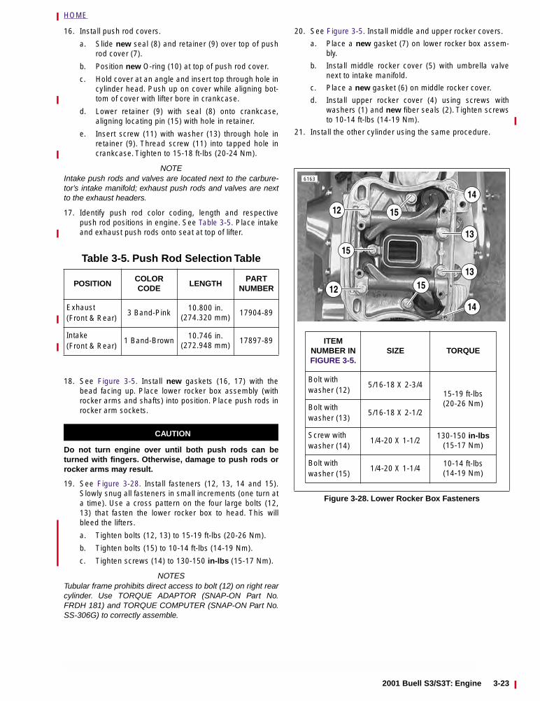
HOME
16. Install push rod covers.
a. Slide new seal (8) and retainer (9) over top of pushrod cover (7).
b. Position new O-ring (10) at top of push rod cover.
c. Hold cover at an angle and insert top through hole incylinder head. Push up on cover while aligning bot-tom of cover with lifter bore in crankcase.
d. Lower retainer (9) with seal (8) onto crankcase,aligning locating pin (15) with hole in retainer.
e. Insert screw (11) with washer (13) through hole inretainer (9). Thread screw (11) into tapped hole incrankcase. Tighten to 15-18 ft-lbs (20-24 Nm).
NOTEIntake push rods and valves are located next to the carbure-tor’s intake manifold; exhaust push rods and valves are nextto the exhaust headers.
17. Identify push rod color coding, length and respectivepush rod positions in engine. See Table 3-5. Place intakeand exhaust push rods onto seat at top of lifter.
18. See Figure 3-5. Install new gaskets (16, 17) with thebead facing up. Place lower rocker box assembly (withrocker arms and shafts) into position. Place push rods inrocker arm sockets.
CAUTION
Do not turn engine over until both push rods can beturned with fingers. Otherwise, damage to push rods orrocker arms may result.
19. See Figure 3-28. Install fasteners (12, 13, 14 and 15).Slowly snug all fasteners in small increments (one turn ata time). Use a cross pattern on the four large bolts (12,13) that fasten the lower rocker box to head. This willbleed the lifters.
a. Tighten bolts (12, 13) to 15-19 ft-lbs (20-26 Nm).
b. Tighten bolts (15) to 10-14 ft-lbs (14-19 Nm).
c. Tighten screws (14) to 130-150 in-lbs (15-17 Nm).
NOTESTubular frame prohibits direct access to bolt (12) on right rearcylinder. Use TORQUE ADAPTOR (SNAP-ON Part No.FRDH 181) and TORQUE COMPUTER (SNAP-ON Part No.SS-306G) to correctly assemble.
20. See Figure 3-5. Install middle and upper rocker covers.
a. Place a new gasket (7) on lower rocker box assem-bly.
b. Install middle rocker cover (5) with umbrella valvenext to intake manifold.
c. Place a new gasket (6) on middle rocker cover.
d. Install upper rocker cover (4) using screws withwashers (1) and new fiber seals (2). Tighten screwsto 10-14 ft-lbs (14-19 Nm).
21. Install the other cylinder using the same procedure.
Table 3-5. Push Rod Selection Table
POSITIONCOLOR CODE
LENGTHPART
NUMBER
Exhaust(Front & Rear)
3 Band-Pink10.800 in.
(274.320 mm)17904-89
Intake(Front & Rear)
1 Band-Brown10.746 in.
(272.948 mm)17897-89
Figure 3-28. Lower Rocker Box Fasteners
ITEMNUMBER INFIGURE 3-5.
SIZE TORQUE
Bolt with washer (12)
5/16-18 X 2-3/415-19 ft-lbs (20-26 Nm)Bolt with
washer (13)5/16-18 X 2-1/2
Screw with washer (14)
1/4-20 X 1-1/2130-150 in-lbs
(15-17 Nm)
Bolt with washer (15)
1/4-20 X 1-1/410-14 ft-lbs(14-19 Nm)
13
14
12
12
15
15
15
14
13
6163
2001 Buell S3/S3T: Engine 3-23
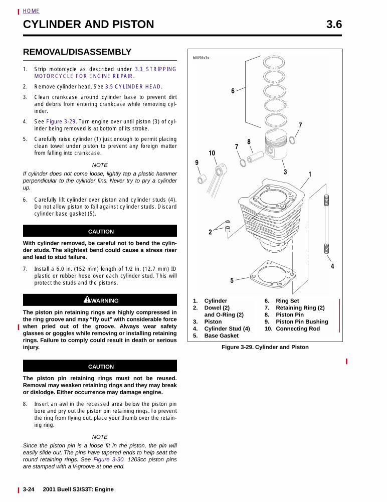
HOME
CYLINDER AND PISTON 3.6
REMOVAL/DISASSEMBLY
1. Strip motorcycle as described under 3.3 STRIPPINGMOTORCYCLE FOR ENGINE REPAIR.
2. Remove cylinder head. See 3.5 CYLINDER HEAD.
3. Clean crankcase around cylinder base to prevent dirtand debris from entering crankcase while removing cyl-inder.
4. See Figure 3-29. Turn engine over until piston (3) of cyl-inder being removed is at bottom of its stroke.
5. Carefully raise cylinder (1) just enough to permit placingclean towel under piston to prevent any foreign matterfrom falling into crankcase.
NOTE
If cylinder does not come loose, lightly tap a plastic hammerperpendicular to the cylinder fins. Never try to pry a cylinderup.
6. Carefully lift cylinder over piston and cylinder studs (4).Do not allow piston to fall against cylinder studs. Discardcylinder base gasket (5).
CAUTION
With cylinder removed, be careful not to bend the cylin-der studs. The slightest bend could cause a stress riserand lead to stud failure.
7. Install a 6.0 in. (152 mm) length of 1/2 in. (12.7 mm) IDplastic or rubber hose over each cylinder stud. This willprotect the studs and the pistons.
11WARNING1WARNING
The piston pin retaining rings are highly compressed inthe ring groove and may “fly out” with considerable forcewhen pried out of the groove. Always wear safetyglasses or goggles while removing or installing retainingrings. Failure to comply could result in death or seriousinjury.
CAUTION
The piston pin retaining rings must not be reused.Removal may weaken retaining rings and they may breakor dislodge. Either occurrence may damage engine.
8. Insert an awl in the recessed area below the piston pinbore and pry out the piston pin retaining rings. To preventthe ring from flying out, place your thumb over the retain-ing ring.
NOTE
Since the piston pin is a loose fit in the piston, the pin willeasily slide out. The pins have tapered ends to help seat theround retaining rings. See Figure 3-30. 1203cc piston pinsare stamped with a V-groove at one end.
Figure 3-29. Cylinder and Piston
1. Cylinder2. Dowel (2)
and O-Ring (2)3. Piston4. Cylinder Stud (4)5. Base Gasket
6. Ring Set7. Retaining Ring (2)8. Piston Pin9. Piston Pin Bushing10. Connecting Rod
710
93
7
2
4
1
6
8
5
b0056x3x
3-24 2001 Buell S3/S3T: Engine
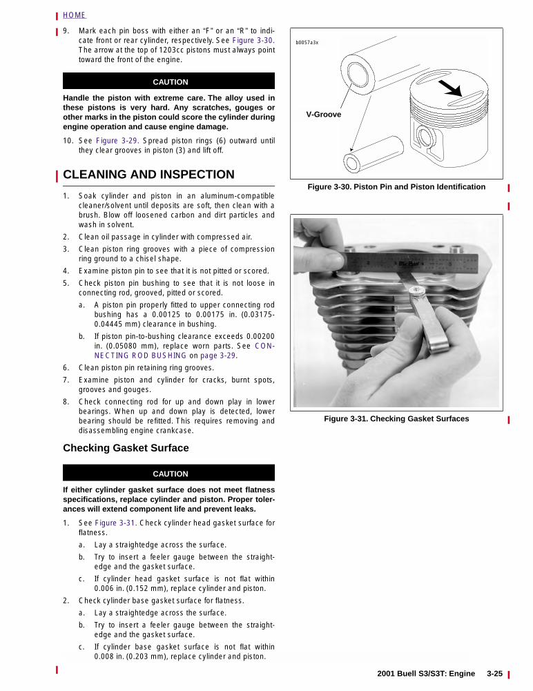
HOME
9. Mark each pin boss with either an “F” or an “R” to indi-cate front or rear cylinder, respectively. See Figure 3-30.The arrow at the top of 1203cc pistons must always pointtoward the front of the engine.
CAUTION
Handle the piston with extreme care. The alloy used inthese pistons is very hard. Any scratches, gouges orother marks in the piston could score the cylinder duringengine operation and cause engine damage.
10. See Figure 3-29. Spread piston rings (6) outward untilthey clear grooves in piston (3) and lift off.
CLEANING AND INSPECTION
1. Soak cylinder and piston in an aluminum-compatiblecleaner/solvent until deposits are soft, then clean with abrush. Blow off loosened carbon and dirt particles andwash in solvent.
2. Clean oil passage in cylinder with compressed air.
3. Clean piston ring grooves with a piece of compressionring ground to a chisel shape.
4. Examine piston pin to see that it is not pitted or scored.
5. Check piston pin bushing to see that it is not loose inconnecting rod, grooved, pitted or scored.
a. A piston pin properly fitted to upper connecting rodbushing has a 0.00125 to 0.00175 in. (0.03175-0.04445 mm) clearance in bushing.
b. If piston pin-to-bushing clearance exceeds 0.00200in. (0.05080 mm), replace worn parts. See CON-NECTING ROD BUSHING on page 3-29.
6. Clean piston pin retaining ring grooves.
7. Examine piston and cylinder for cracks, burnt spots,grooves and gouges.
8. Check connecting rod for up and down play in lowerbearings. When up and down play is detected, lowerbearing should be refitted. This requires removing anddisassembling engine crankcase.
Checking Gasket Surface
CAUTION
If either cylinder gasket surface does not meet flatnessspecifications, replace cylinder and piston. Proper toler-ances will extend component life and prevent leaks.
1. See Figure 3-31. Check cylinder head gasket surface forflatness.
a. Lay a straightedge across the surface.
b. Try to insert a feeler gauge between the straight-edge and the gasket surface.
c. If cylinder head gasket surface is not flat within0.006 in. (0.152 mm), replace cylinder and piston.
2. Check cylinder base gasket surface for flatness.
a. Lay a straightedge across the surface.
b. Try to insert a feeler gauge between the straight-edge and the gasket surface.
c. If cylinder base gasket surface is not flat within0.008 in. (0.203 mm), replace cylinder and piston.
Figure 3-30. Piston Pin and Piston Identification
Figure 3-31. Checking Gasket Surfaces
b0057a3x
V-Groove
2001 Buell S3/S3T: Engine 3-25
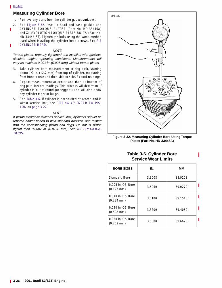
HOME
Measuring Cylinder Bore 1. Remove any burrs from the cylinder gasket surfaces.
2. See Figure 3-32. Install a head and base gasket, andCYLINDER TORQUE PLATES (Part No. HD-33446A)and XL EVOLUTION TORQUE PLATE BOLTS (Part No.HD-33446-86). Tighten the bolts using the same methodused when installing the cylinder head screws. See 3.5CYLINDER HEAD.
NOTETorque plates, properly tightened and installed with gaskets,simulate engine operating conditions. Measurements willvary as much as 0.001 in. (0.025 mm) without torque plates.
3. Take cylinder bore measurement in ring path, startingabout 1/2 in. (12.7 mm) from top of cylinder, measuringfrom front to rear and then side to side. Record readings.
4. Repeat measurement at center and then at bottom ofring path. Record readings. This process will determine ifcylinder is out-of-round (or “egged”) and will also showany cylinder taper or bulge.
5. See Table 3-6. If cylinder is not scuffed or scored and iswithin service limit, see FITTING CYLINDER TO PIS-TON on page 3-27.
NOTEIf piston clearance exceeds service limit, cylinders should berebored and/or honed to next standard oversize, and refittedwith the corresponding piston and rings. Do not fit pistontighter than 0.0007 in. (0.0178 mm). See 3.1 SPECIFICA-TIONS.
Figure 3-32. Measuring Cylinder Bore Using Torque Plates (Part No. HD-33446A)
Table 3-6. Cylinder Bore Service Wear Limits
BORE SIZES IN. MM
Standard Bore 3.5008 88.9203
0.005 in. OS Bore(0.127 mm)
3.5050 89.0270
0.010 in. OS Bore(0.254 mm)
3.5100 89.1540
0.020 in. OS Bore(0.508 mm)
3.5200 89.4080
0.030 in. OS Bore(0.762 mm)
3.5300 89.6620
b0306x3x
3-26 2001 Buell S3/S3T: Engine
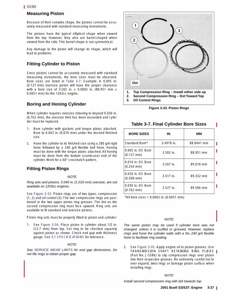
HOME
Measuring Piston
Because of their complex shape, the pistons cannot be accu-rately measured with standard measuring instruments.
The pistons have the typical elliptical shape when viewedfrom the top. However, they also are barrel-shaped whenviewed from the side. This barrel shape is not symmetrical.
Any damage to the piston will change its shape, which willlead to problems.
Fitting Cylinder to Piston
Since pistons cannot be accurately measured with standardmeasuring instruments, the bore sizes must be observed.Bore sizes are listed in Table 3-7. Example: A 0.005 in.(0.127 mm) oversize piston will have the proper clearancewith a bore size of 3.502 in. ± 0.0002 in. (88.951 mm ±0.0051 mm) for the 1203cc engine.
Boring and Honing Cylinder
When cylinder requires oversize reboring to beyond 0.030 in.(0.762 mm), the oversize limit has been exceeded and cylin-der must be replaced.
1. Bore cylinder with gaskets and torque plates attached.Bore to 0.003 in. (0.076 mm) under the desired finishedsize.
2. Hone the cylinder to its finished size using a 280 grit rigidhone followed by a 240 grit flexible ball hone. Honingmust be done with the torque plates attached. All honingmust be done from the bottom (crankcase) end of thecylinder. Work for a 60° crosshatch pattern.
Fitting Piston Rings
NOTE
Ring sets and pistons, 0.040 in. (1.016 mm) oversize, are notavailable on 1203cc engines.
See Figure 3-33. Piston rings are of two types: compression(1, 2) and oil control (3). The two compression rings are posi-tioned in the two upper piston ring grooves. The dot on thesecond compression ring must face upward. Ring sets areavailable to fit standard and oversize pistons.
Piston ring sets must be properly fitted to piston and cylinder:
1. See Figure 3-34. Place piston in cylinder about 1/2 in.(12.7 mm) from top. Set ring to be checked squarelyagainst piston as shown. Check end gap with thicknessgauge. See 3.1 SPECIFICATIONS for tolerance.
NOTE
See SERVICE WEAR LIMITS for end gap dimensions. Donot file rings to obtain proper gap.
NOTE
The same piston may be used if cylinder bore was notchanged, unless it is scuffed or grooved. However, replacerings and hone the cylinder walls with a No. 240 grit flexiblehone to facilitate ring seating.
2. See Figure 3-35. Apply engine oil to piston grooves. UseTRANSMISSION SHAFT RETAINING RING PLIERS(Part No. J-5586) to slip compression rings over pistoninto their respective grooves. Be extremely careful not toover expand, twist rings or damage piston surface wheninstalling rings.
NOTE
Install second compression ring with dot towards top.
Figure 3-33. Piston Rings
Table 3-7. Final Cylinder Bore Sizes
BORE SIZES IN. MM
Standard Bore* 3.4978 in. 88.8441 mm
0.005 in. OS Bore(0.127 mm)
3.502 in. 88.951 mm
0.010 in. OS Bore(0.254 mm)
3.507 in. 89.078 mm
0.020 in. OS Bore(0.508 mm)
3.517 in. 89.332 mm
0.030 in. OS Bore(0.762 mm)
3.527 in. 89.586 mm
*All bore sizes + 0.0002 in. (0.0051 mm)
1. Top Compression Ring – Install either side up2. Second Compression Ring – Dot Toward Top3. Oil Control Rings
2
13
2747a
Dot
2001 Buell S3/S3T: Engine 3-27
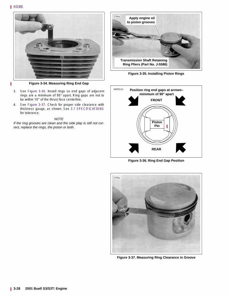
HOME
3. See Figure 3-36. Install rings so end gaps of adjacentrings are a minimum of 90° apart. Ring gaps are not tobe within 10° of the thrust face centerline.
4. See Figure 3-37. Check for proper side clearance withthickness gauge, as shown. See 3.1 SPECIFICATIONSfor tolerance.
NOTEIf the ring grooves are clean and the side play is still not cor-rect, replace the rings, the piston or both.
Figure 3-34. Measuring Ring End Gap
Figure 3-35. Installing Piston Rings
Figure 3-36. Ring End Gap Position
Figure 3-37. Measuring Ring Clearance in Groove
2784a Apply engine oilto piston grooves
Transmission Shaft RetainingRing Pliers (Part No. J-5586)
Position ring end gaps at arrows–minimum of 90° apart
FRONT
Piston Pin
REAR
b0095x3x
2785a
3-28 2001 Buell S3/S3T: Engine
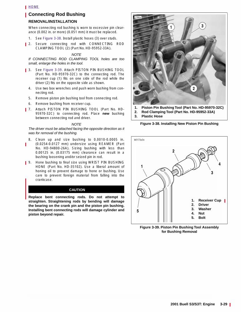
HOME
Connecting Rod BushingREMOVAL/INSTALLATION
When connecting rod bushing is worn to excessive pin clear-ance (0.002 in. or more) (0.051 mm) it must be replaced.
1. See Figure 3-38. Install plastic hoses (3) over studs.
2. Secure connecting rod with CONNECTING RODCLAMPING TOOL (2) (Part No. HD-95952-33A).
NOTEIf CONNECTING ROD CLAMPING TOOL holes are toosmall, enlarge the holes in the tool.
3. See Figure 3-39. Attach PISTON PIN BUSHING TOOL(Part No. HD-95970-32C) to the connecting rod. Thereceiver cup (1) fits on one side of the rod while thedriver (2) fits on the opposite side as shown.
4. Use two box wrenches and push worn bushing from con-necting rod.
5. Remove piston pin bushing tool from connecting rod.
6. Remove bushing from receiver cup.
7. Attach PISTON PIN BUSHING TOOL (Part No. HD-95970-32C) to connecting rod. Place new bushingbetween connecting rod and driver.
NOTEThe driver must be attached facing the opposite direction as itwas for removal of the bushing.
8. Clean up and size bushing to 0.0010-0.0005 in.(0.0254-0.0127 mm) undersize using REAMER (PartNo. HD-94800-26A). Sizing bushing with less than0.00125 in. (0.03175 mm) clearance can result in abushing loosening and/or seized pin in rod.
9. Hone bushing to final size using WRIST PIN BUSHINGHONE (Part No. HD-35102). Use a liberal amount ofhoning oil to prevent damage to hone or bushing. Usecare to prevent foreign material from falling into thecrankcase.
CAUTION
Replace bent connecting rods. Do not attempt tostraighten. Straightening rods by bending will damagethe bearing on the crank pin and the piston pin bushing.Installing bent connecting rods will damage cylinder andpiston beyond repair.
Figure 3-38. Installing New Piston Pin Bushing
Figure 3-39. Piston Pin Bushing Tool Assembly for Bushing Removal
2786a
1. Piston Pin Bushing Tool (Part No. HD-95970-32C)2. Rod Clamping Tool (Part No. HD-95952-33A)3. Plastic Hose
2
1 3
1. Receiver Cup2. Driver3. Washer4. Nut5. Bolt
b0173a3x
1
2
3
4
5
2001 Buell S3/S3T: Engine 3-29
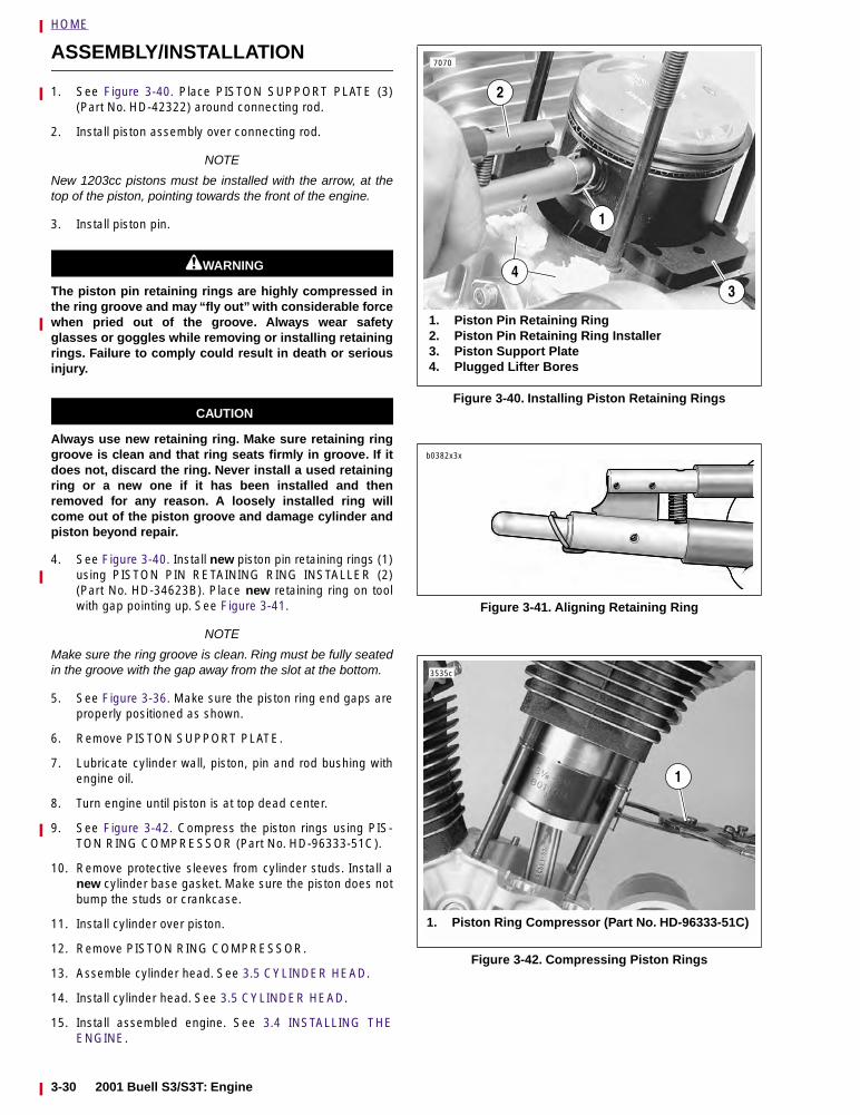
HOME
ASSEMBLY/INSTALLATION
1. See Figure 3-40. Place PISTON SUPPORT PLATE (3)(Part No. HD-42322) around connecting rod.
2. Install piston assembly over connecting rod.
NOTE
New 1203cc pistons must be installed with the arrow, at thetop of the piston, pointing towards the front of the engine.
3. Install piston pin.
11WARNING1WARNING
The piston pin retaining rings are highly compressed inthe ring groove and may “fly out” with considerable forcewhen pried out of the groove. Always wear safetyglasses or goggles while removing or installing retainingrings. Failure to comply could result in death or seriousinjury.
CAUTION
Always use new retaining ring. Make sure retaining ringgroove is clean and that ring seats firmly in groove. If itdoes not, discard the ring. Never install a used retainingring or a new one if it has been installed and thenremoved for any reason. A loosely installed ring willcome out of the piston groove and damage cylinder andpiston beyond repair.
4. See Figure 3-40. Install new piston pin retaining rings (1)using PISTON PIN RETAINING RING INSTALLER (2)(Part No. HD-34623B). Place new retaining ring on toolwith gap pointing up. See Figure 3-41.
NOTE
Make sure the ring groove is clean. Ring must be fully seatedin the groove with the gap away from the slot at the bottom.
5. See Figure 3-36. Make sure the piston ring end gaps areproperly positioned as shown.
6. Remove PISTON SUPPORT PLATE.
7. Lubricate cylinder wall, piston, pin and rod bushing withengine oil.
8. Turn engine until piston is at top dead center.
9. See Figure 3-42. Compress the piston rings using PIS-TON RING COMPRESSOR (Part No. HD-96333-51C).
10. Remove protective sleeves from cylinder studs. Install anew cylinder base gasket. Make sure the piston does notbump the studs or crankcase.
11. Install cylinder over piston.
12. Remove PISTON RING COMPRESSOR.
13. Assemble cylinder head. See 3.5 CYLINDER HEAD.
14. Install cylinder head. See 3.5 CYLINDER HEAD.
15. Install assembled engine. See 3.4 INSTALLING THEENGINE.
Figure 3-40. Installing Piston Retaining Rings
Figure 3-41. Aligning Retaining Ring
Figure 3-42. Compressing Piston Rings
1
7070
1. Piston Pin Retaining Ring2. Piston Pin Retaining Ring Installer 3. Piston Support Plate4. Plugged Lifter Bores
3
2
4
b0382x3x
3535c
1
1. Piston Ring Compressor (Part No. HD-96333-51C)
3-30 2001 Buell S3/S3T: Engine
HOME
3
LUBRICATION SYSTEM 3.7
CHECKING AND ADDING OIL
Check engine oil level in oil tank at least once every 500miles (800 km). Check level more frequently if engine usesmore oil than normal or if vehicle is operated under harshconditions. Oil tank capacity with filter change is 2.0 quarts(1.89 liters).
CHANGING OIL AND FILTER
After a new engine has run its first 500 miles (800 km) and at5000 mile (8000 km) intervals or annually thereafter, com-pletely drain oil tank of used oil. Refill with fresh oil. If vehicleis driven extremely hard, used in competition or driven ondusty roads, change engine oil at shorter intervals. Alwayschange oil filter when changing engine oil.
NOTE
See 1.4 ENGINE LUBRICATION SYSTEM for more informa-tion on checking oil level and changing oil and filter.
WINTER LUBRICATION
Normal fuel combustion in a gasoline engine produces watervapor and carbon dioxide along with other gases and particu-lates. When first starting and warming an engine, some of thewater vapor that gets into the engine crankcase condenses toform liquid water. If the engine is driven long enough to thor-oughly warm the crankcase, most of this liquid water is againvaporized and exhausted through the crankcase breathersystem.
A moderately driven vehicle making short runs may not beable to vacate water vapors allowing liquid water to accumu-late in the oil tank. This is especially true if the vehicle is oper-ated in cold weather. In freezing weather, an accumulation ofwater in the engine oil may become slush or ice, which canblock oil lines and lead to severe engine damage. Waterremaining in the engine oil for long periods of time can forman acidic sludge that is corrosive to metal engine parts andcauses accelerated wear of moving components.
In winter the oil change interval should be shorter than nor-mal. The colder the weather, the shorter the recommendedoil change interval. A vehicle used only for short runs in coldweather must have the engine oil drained frequently.
2001 Buell S3/S3T: Engine 3-31
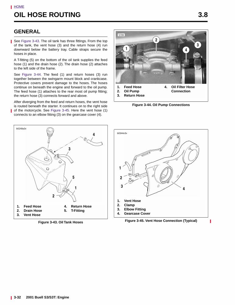
HOME
OIL HOSE ROUTING 3.8
GENERAL
See Figure 3-43. The oil tank has three fittings. From the topof the tank, the vent hose (3) and the return hose (4) rundownward below the battery tray. Cable straps secure thehoses in place.
A T-fitting (5) on the bottom of the oil tank supplies the feedhose (1) and the drain hose (2). The drain hose (2) attachesto the left side of the frame.
See Figure 3-44. The feed (1) and return hoses (3) runtogether between the swingarm mount block and crankcase.Protective covers prevent damage to the hoses. The hosescontinue on beneath the engine and forward to the oil pump.The feed hose (1) attaches to the rear most oil pump fitting;the return hose (3) connects forward and above.
After diverging from the feed and return hoses, the vent hoseis routed beneath the starter. It continues on to the right sideof the motorcycle. See Figure 3-45. Here the vent hose (1)connects to an elbow fitting (3) on the gearcase cover (4).
Figure 3-43. Oil Tank Hoses
b0248a3x
2
1. Feed Hose 2. Drain Hose 3. Vent Hose
4. Return Hose 5. T-Fitting
1
4
3
5
Figure 3-44. Oil Pump Connections
Figure 3-45. Vent Hose Connection (Typical)
13
4
1. Feed Hose 2. Oil Pump3. Return Hose
4. Oil Filter HoseConnection
5709
2
b0344x3x
1. Vent Hose 2. Clamp 3. Elbow Fitting4. Gearcase Cover
1
3
2
4
3-32 2001 Buell S3/S3T: Engine
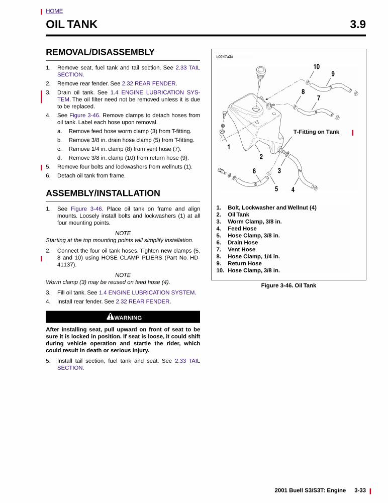
HOME
OIL TANK 3.9
REMOVAL/DISASSEMBLY
1. Remove seat, fuel tank and tail section. See 2.33 TAILSECTION.
2. Remove rear fender. See 2.32 REAR FENDER.
3. Drain oil tank. See 1.4 ENGINE LUBRICATION SYS-TEM. The oil filter need not be removed unless it is dueto be replaced.
4. See Figure 3-46. Remove clamps to detach hoses fromoil tank. Label each hose upon removal.
a. Remove feed hose worm clamp (3) from T-fitting.
b. Remove 3/8 in. drain hose clamp (5) from T-fitting.
c. Remove 1/4 in. clamp (8) from vent hose (7).
d. Remove 3/8 in. clamp (10) from return hose (9).
5. Remove four bolts and lockwashers from wellnuts (1).
6. Detach oil tank from frame.
ASSEMBLY/INSTALLATION
1. See Figure 3-46. Place oil tank on frame and alignmounts. Loosely install bolts and lockwashers (1) at allfour mounting points.
NOTEStarting at the top mounting points will simplify installation.
2. Connect the four oil tank hoses. Tighten new clamps (5,8 and 10) using HOSE CLAMP PLIERS (Part No. HD-41137).
NOTEWorm clamp (3) may be reused on feed hose (4).
3. Fill oil tank. See 1.4 ENGINE LUBRICATION SYSTEM.
4. Install rear fender. See 2.32 REAR FENDER.
11WARNING1WARNING
After installing seat, pull upward on front of seat to besure it is locked in position. If seat is loose, it could shiftduring vehicle operation and startle the rider, whichcould result in death or serious injury.
5. Install tail section, fuel tank and seat. See 2.33 TAILSECTION.
Figure 3-46. Oil Tank
b0247a3x
3
1. Bolt, Lockwasher and Wellnut (4)2. Oil Tank3. Worm Clamp, 3/8 in.4. Feed Hose 5. Hose Clamp, 3/8 in. 6. Drain Hose 7. Vent Hose 8. Hose Clamp, 1/4 in.9. Return Hose 10. Hose Clamp, 3/8 in.
45
6
78
109
12
T-Fitting on Tank
2001 Buell S3/S3T: Engine 3-33
HOME
OIL PRESSURE INDICATOR SWITCH 3.10
GENERAL
The oil pressure indicator switch is a pressure-actuated dia-phragm-type switch. When oil is not circulating through thesystem or when oil pressure is abnormally low, spring tensionholds the switch contacts closed, thereby completing the sig-nal light circuit and causing the indicator lamp to illuminate.
OIL PRESSURESIGNAL LIGHT
The oil pressure signal light turns ON when:
● Ignition switch is turned on prior to starting engine.
● Oil is not circulating through the running engine.
● Oil pressure is abnormally low on the running engine.
● Engine is idling far below 1000 RPM.
The oil pressure signal light turns OFF when:
● Oil is circulating with adequate pressure through theengine running at 1000 RPM or greater.
Troubleshooting information is listed in Table 3-8.
NOTE
If the ignition is turned back on immediately after the engineis stopped, the oil light may not turn on right away because ofoil pressure retained in the filter housing.
OIL PRESSURE
See Figure 3-47. The oil pump is nonregulatory and deliversits entire volume of oil under pressure to the oil filter mount.When an engine is cold, the engine oil will be more viscous(i.e., thicker). During start-up of a cold engine, oil pressurewill be higher than normal and oil circulation will be some-what restricted within the oiling system. As the engine warmsto normal operating temperature, the engine oil will warm upand become less viscous — oil pressure decreases.
When an engine is operated at high speeds, the volume of oilcirculated through the oiling system increases, resulting inhigher oil pressure. As engine speed is reduced, the volumeof oil pumped is also reduced, resulting in lower oil pressure.
To check oil pressure, use OIL PRESSURE GAUGE (Part No.HD-96921-52A) and OIL PRESSURE GAUGE ADAPTER(Part No. HD-96940-52A). Remove oil pressure indicatorswitch and insert pressure gauge fitting. See Figure 3-48.
Ride motorcycle at least 20 miles (32 km) at or above 50MPH (80 KM/H) until engine oil reaches normal operatingtemperature. At 2500 RPM, oil pressure will vary from 10-17psi (69-117 kN/m2). At idle speed (950-1050 RPM), oil pres-sure will vary from 7-12 psi (48-83 kN/m2).
Figure 3-47. Checking Oil Pressure (Typical)
Figure 3-48. Oil Pressure Indicator Switch
Table 3-8. Troubleshooting Oil Pressure Signal Light
LIGHT PROBABLE CAUSES
Stays on at speeds above idle.
● Empty oil tank.● Clogged feed line (ice and sludge,
freezing temperatures).● Air-bound oil line.● Grounded oil switch wire.● Malfunctioning signal switch.● Diluted oil.● Malfunctioning check valve (see
3.14 OIL FILTER MOUNT).
Flickers at idle. ● Incorrect idle speed. Malfunction-ing or improperly installed checkvalve (see 3.14 OIL FILTERMOUNT).
Does not glow when ignition is turned on (prior to oper-ating engine).
● Malfunctioning signal switch.● Malfunction in wiring.● Burned-out signal bulb.● Dead battery (see NOTE above).
b0350x3x
6218
Oil Filter
Switch
3-34 2001 Buell S3/S3T: Engine
HOME
CRANKCASE BREATHING SYSTEM 3.11
GENERAL
See Figure 3-49. On piston downstroke, a mixture of crank-case air and oil mist is vented up the push rod covers (1)through an umbrella valve (3) in each middle rocker box sec-tion.
The oil mist separates from the crankcase air, collects andpasses through a small drain hole (2) where it eventuallyreturns to the crankcase.
The crankcase air is routed through a passage in each cylin-der head. The air then travels through each air cleanerbreather bolt (4). Hoses leading from the air cleaner boltsvent the air to the air cleaner’s snorkel.
Figure 3-49. Crankcase Breathing System,Typical Cylinder
1. Push Rod Cover (2)2. Oil Drain Hole3. Umbrella Valve4. Breather Bolt
b0143b3x
1
4
2
3
2001 Buell S3/S3T: Engine 3-35
HOME
OILING SYSTEM (COLOR FOLDOUT) 3.12
NOTEThe following paragraph numbers correspond with the num-bered callouts in the INTERNAL ENGINE PASSAGES illus-tration.
1. Oil is gravity-fed from the oil tank to the gerotor-style oilpump through a feed hose. Oil enters the feed sectionand fills a cavity located under the feed pump.
NOTESee 3.13 OIL PUMP for a complete explanation of the gerotorpump sets.
2. The feed pump transfers oil from the inlet cavity throughthe feed hose to the oil filter mount.
3. Oil flows through the filter mount cavity to the oil filter.
4. Oil enters the peripheral cavity of the oil filter, passesthrough the filtering medium into the central cavity of theoil filter, and flows into the filter adapter (fitting whichconnects filter to filter mount).
5. Adequate oil pressure in the filter mount cavity activatesthe oil pressure signal light switch and shuts off the oilpressure signal light.
6. Oil flowing from the filter adapter opens the check ball.The check ball opens at 4-6 psi (28-41 kN/m2) oil pres-sure.
7. With the check ball open, oil flows into the crankcasefeed galley.
8. Oil flows through the feed galley in the crankcase to thelifter blocks and hydraulic lifters. Cross-drilled pas-sages intersect the main feed galley and carry oil toeach hydraulic lifter.
9. Oil also enters an intersecting passage in the gearcasecover. Oil flow is then routed to the crankshaft area.
10. Oil enters a hole in the end of the pinion gear shaft andtravels to the right flywheel where it is routed through theflywheel to the crankpin. Oil is forced through the crank-pin to properly lubricate the rod bearing assembly.
11. Oil flows up passages in the push rods to the rockerarm shafts and bushings.
12. The valve stems are lubricated by oil supplied throughdrilled oil holes in the rocker arms.
13. Oil collected in the push rod areas of the cylinder headsflows down the push rod covers, through drain holes inthe lifter blocks and into the gearcase.
14. Feed oil to the rocker area is returned to the crankcasethrough a passage in the head and cylinder.
15. Oil collected in the sump is splash-fed to the pistons,cylinder walls and flywheel components.
16. Oil collected in the sump area returns to the scavengesection of the oil pump through a passage located in therear section of the sump. Oil flow to the pump is accom-plished by the scavenging effect of the pump and by thepressure created by the downward stroke of the pistons.
17. Return oil fills a cavity above the pump's return gears.The return gears pump oil back to the oil tank.
18. A small amount of oil flows from the feed galley in theright crankcase half through a restricted orifice, whichsprays the oil onto the rear intake cam gear in the gear-case. Oil is transferred to the teeth of all the cam gearsthrough the gear meshing action.
3-36 2001 Buell S3/S3T: Engine

2001 Buell S3/S3T: Engine 3-63
HOME
RETURN OIL
FEED OIL
RETURN OIL
FEED OIL
INTERNAL ENGINE PASSAGES
HOME
OIL PUMP 3.13
MODEL YEAR CHANGE
All 2001 Buell Air Twin Models have a new oil pump with amodified casting that allows for better scavenging. All wearlimits and specifications remain the same as previous years.
GENERAL
See Figure 3-50. The oil pump consists of two gerotor gearsets, feed and scavenge (return), housed in one pump body.The feed set distributes oil to the engine, the scavenge setreturns oil to the tank. The pump body features ”split kidney”scavenge ports.
A gerotor-type gear set has two parts — an inner and anouter gerotor. The inner gerotor has one less tooth than theouter gerotor. Both gerotors have fixed centers which are off-set to each other.
In a gerotor gear set, oil is transferred from inlet to outlet as itis trapped between the rotating inner and outer gerotors. Theillustration below shows the principle of gerotor operation:
1. During the first 180° of rotation, the cavity between innerand outer gerotors gradually increases in size until itreaches its maximum size, equivalent to the full volume
of the “missing tooth.” The gradually enlarging cavity cre-ates a vacuum into which oil flows from the inlet.
2. During the next 180° of rotation, the size of the cavitydecreases forcing oil into the outlet.
See Figure 3-52. Gravity-fed oil from the oil tank enters thepump through the feed hose connector (5). It is forced by thegerotor feed set (7) through a hose to the oil filter. Return oilfrom the flywheel compartment is drawn back into the pumpand is forced by the gerotor scavenge set (9) back to the oiltank.
See INTERNAL ENGINE PASSAGES for oil passages withinthe engine.
The oil pump seldom needs servicing. Before you disassem-ble an oil pump suspected of not producing adequate oilpressure, be absolutely certain that all possible related mal-functions have been eliminated:
1. Make sure all oil hose clamps are tight and that hosesare not pinched or damaged.
2. Check oil level and condition of oil in tank. Pressure willbe affected if oil is diluted. In freezing weather, propercirculation of oil can be affected if the oil feed hosebecomes clogged with ice and sludge.
3. Check for a grounded oil pressure switch wire or faultyswitch if oil indicator light fails to go out with engine running.
Figure 3-50. Principle of Gerotor Operation
OilOutlet
Inner Gerotor
b0098x3x
Outer Gerotor
Oil Inlet Oil Outlet
Oil drawn into cavity between gerotor teeth
1 2
3 4
Oil forced out
Oil Inlet
Oil Outlet
Oil trapped between gerotor teeth
Oil trapped between innerand outer gerotor teeth
2001 Buell S3/S3T: Engine 3-37
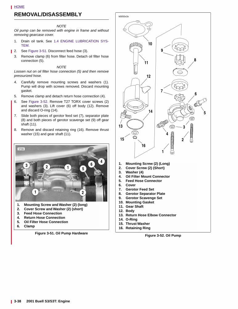
HOME
REMOVAL/DISASSEMBLY
NOTEOil pump can be removed with engine in frame and withoutremoving gearcase cover.
1. Drain oil tank. See 1.4 ENGINE LUBRICATION SYS-TEM.
2. See Figure 3-51. Disconnect feed hose (3).
3. Remove clamp (6) from filter hose. Detach oil filter hoseconnection (5).
NOTELoosen nut on oil filter hose connection (5) and then removepressurized hose.
4. Carefully remove mounting screws and washers (1).Pump will drop with screws removed. Discard mountinggasket.
5. Remove clamp and detach return hose connection (4).
6. See Figure 3-52. Remove T27 TORX cover screws (2)and washers (3). Lift cover (6) off body (12). Removeand discard O-ring (14).
7. Slide both pieces of gerotor feed set (7), separator plate(8) and both pieces of gerotor scavenge set (9) off gearshaft (11).
8. Remove and discard retaining ring (16). Remove thrustwasher (15) and gear shaft (11).
Figure 3-51. Oil Pump Hardware
3 2
1
14
5
1. Mounting Screw and Washer (2) (long)2. Cover Screw and Washer (2) (short)3. Feed Hose Connection4. Return Hose Connection5. Oil Filter Hose Connection6. Clamp
5709
2
6
Figure 3-52. Oil Pump
1
2
3
4
5
8
10
11
6
13
14
15
16
1. Mounting Screw (2) (Long) 2. Cover Screw (2) (Short)3. Washer (4)4. Oil Filter Mount Connector5. Feed Hose Connector6. Cover 7. Gerotor Feed Set8. Gerotor Separator Plate9. Gerotor Scavenge Set10. Mounting Gasket11. Gear Shaft12. Body 13. Return Hose Elbow Connector14. O-Ring15. Thrust Washer16. Retaining Ring
12
b0055x3x
9
7
3-38 2001 Buell S3/S3T: Engine
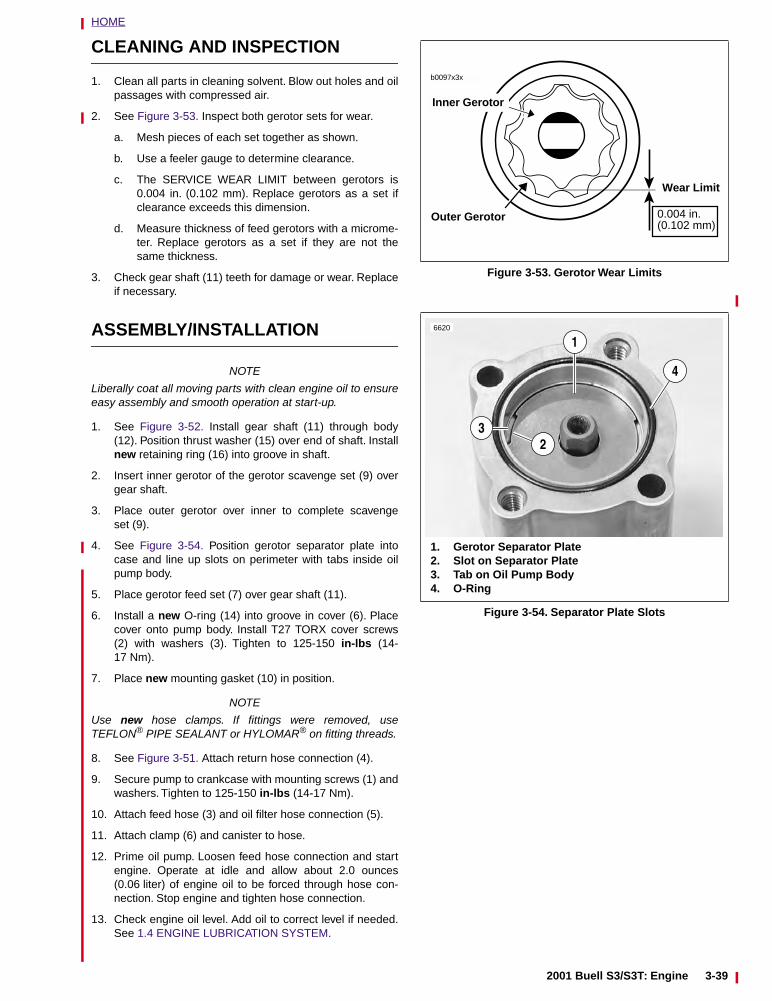
HOME
CLEANING AND INSPECTION
1. Clean all parts in cleaning solvent. Blow out holes and oilpassages with compressed air.
2. See Figure 3-53. Inspect both gerotor sets for wear.
a. Mesh pieces of each set together as shown.
b. Use a feeler gauge to determine clearance.
c. The SERVICE WEAR LIMIT between gerotors is0.004 in. (0.102 mm). Replace gerotors as a set ifclearance exceeds this dimension.
d. Measure thickness of feed gerotors with a microme-ter. Replace gerotors as a set if they are not thesame thickness.
3. Check gear shaft (11) teeth for damage or wear. Replaceif necessary.
ASSEMBLY/INSTALLATION
NOTE
Liberally coat all moving parts with clean engine oil to ensureeasy assembly and smooth operation at start-up.
1. See Figure 3-52. Install gear shaft (11) through body(12). Position thrust washer (15) over end of shaft. Installnew retaining ring (16) into groove in shaft.
2. Insert inner gerotor of the gerotor scavenge set (9) overgear shaft.
3. Place outer gerotor over inner to complete scavengeset (9).
4. See Figure 3-54. Position gerotor separator plate intocase and line up slots on perimeter with tabs inside oilpump body.
5. Place gerotor feed set (7) over gear shaft (11).
6. Install a new O-ring (14) into groove in cover (6). Placecover onto pump body. Install T27 TORX cover screws(2) with washers (3). Tighten to 125-150 in-lbs (14-17 Nm).
7. Place new mounting gasket (10) in position.
NOTE
Use new hose clamps. If fittings were removed, useTEFLON® PIPE SEALANT or HYLOMAR® on fitting threads.
8. See Figure 3-51. Attach return hose connection (4).
9. Secure pump to crankcase with mounting screws (1) andwashers. Tighten to 125-150 in-lbs (14-17 Nm).
10. Attach feed hose (3) and oil filter hose connection (5).
11. Attach clamp (6) and canister to hose.
12. Prime oil pump. Loosen feed hose connection and startengine. Operate at idle and allow about 2.0 ounces(0.06 liter) of engine oil to be forced through hose con-nection. Stop engine and tighten hose connection.
13. Check engine oil level. Add oil to correct level if needed.See 1.4 ENGINE LUBRICATION SYSTEM.
Figure 3-53. Gerotor Wear Limits
Figure 3-54. Separator Plate Slots
Inner Gerotor
b0097x3x
Outer Gerotor
Wear Limit
0.004 in.(0.102 mm)
16620
23
1. Gerotor Separator Plate2. Slot on Separator Plate 3. Tab on Oil Pump Body4. O-Ring
4
2001 Buell S3/S3T: Engine 3-39
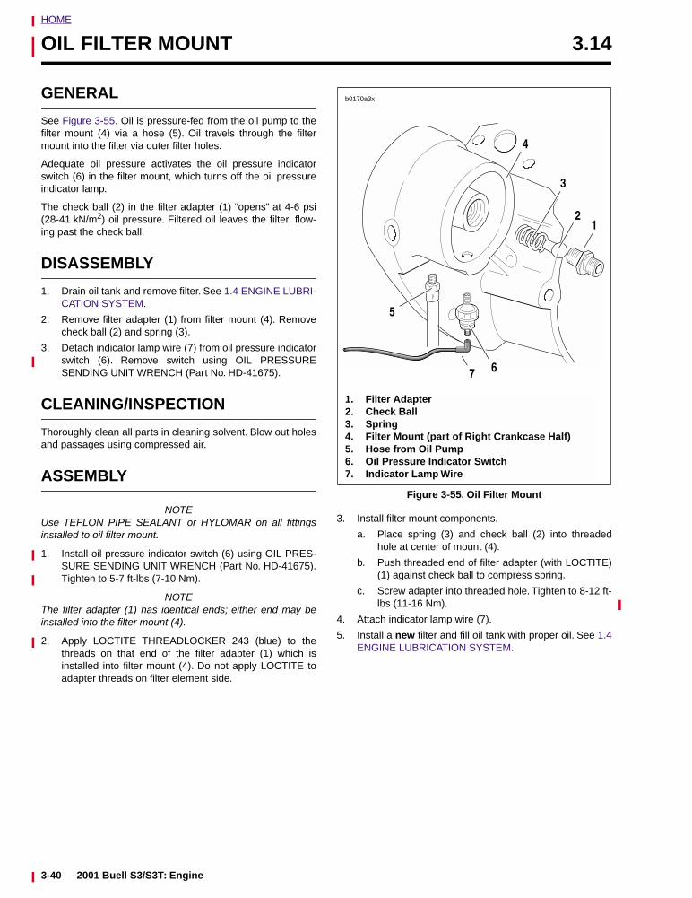
HOME
OIL FILTER MOUNT 3.14
GENERAL
See Figure 3-55. Oil is pressure-fed from the oil pump to thefilter mount (4) via a hose (5). Oil travels through the filtermount into the filter via outer filter holes.
Adequate oil pressure activates the oil pressure indicatorswitch (6) in the filter mount, which turns off the oil pressureindicator lamp.
The check ball (2) in the filter adapter (1) “opens” at 4-6 psi(28-41 kN/m2) oil pressure. Filtered oil leaves the filter, flow-ing past the check ball.
DISASSEMBLY
1. Drain oil tank and remove filter. See 1.4 ENGINE LUBRI-CATION SYSTEM.
2. Remove filter adapter (1) from filter mount (4). Removecheck ball (2) and spring (3).
3. Detach indicator lamp wire (7) from oil pressure indicatorswitch (6). Remove switch using OIL PRESSURESENDING UNIT WRENCH (Part No. HD-41675).
CLEANING/INSPECTION
Thoroughly clean all parts in cleaning solvent. Blow out holesand passages using compressed air.
ASSEMBLY
NOTEUse TEFLON PIPE SEALANT or HYLOMAR on all fittingsinstalled to oil filter mount.
1. Install oil pressure indicator switch (6) using OIL PRES-SURE SENDING UNIT WRENCH (Part No. HD-41675).Tighten to 5-7 ft-lbs (7-10 Nm).
NOTEThe filter adapter (1) has identical ends; either end may beinstalled into the filter mount (4).
2. Apply LOCTITE THREADLOCKER 243 (blue) to thethreads on that end of the filter adapter (1) which isinstalled into filter mount (4). Do not apply LOCTITE toadapter threads on filter element side.
3. Install filter mount components.
a. Place spring (3) and check ball (2) into threadedhole at center of mount (4).
b. Push threaded end of filter adapter (with LOCTITE)(1) against check ball to compress spring.
c. Screw adapter into threaded hole. Tighten to 8-12 ft-lbs (11-16 Nm).
4. Attach indicator lamp wire (7).
5. Install a new filter and fill oil tank with proper oil. See 1.4ENGINE LUBRICATION SYSTEM.
Figure 3-55. Oil Filter Mount
1. Filter Adapter2. Check Ball3. Spring4. Filter Mount (part of Right Crankcase Half)5. Hose from Oil Pump6. Oil Pressure Indicator Switch7. Indicator Lamp Wire
3
6
21
4
b0170a3x
5
7
3-40 2001 Buell S3/S3T: Engine
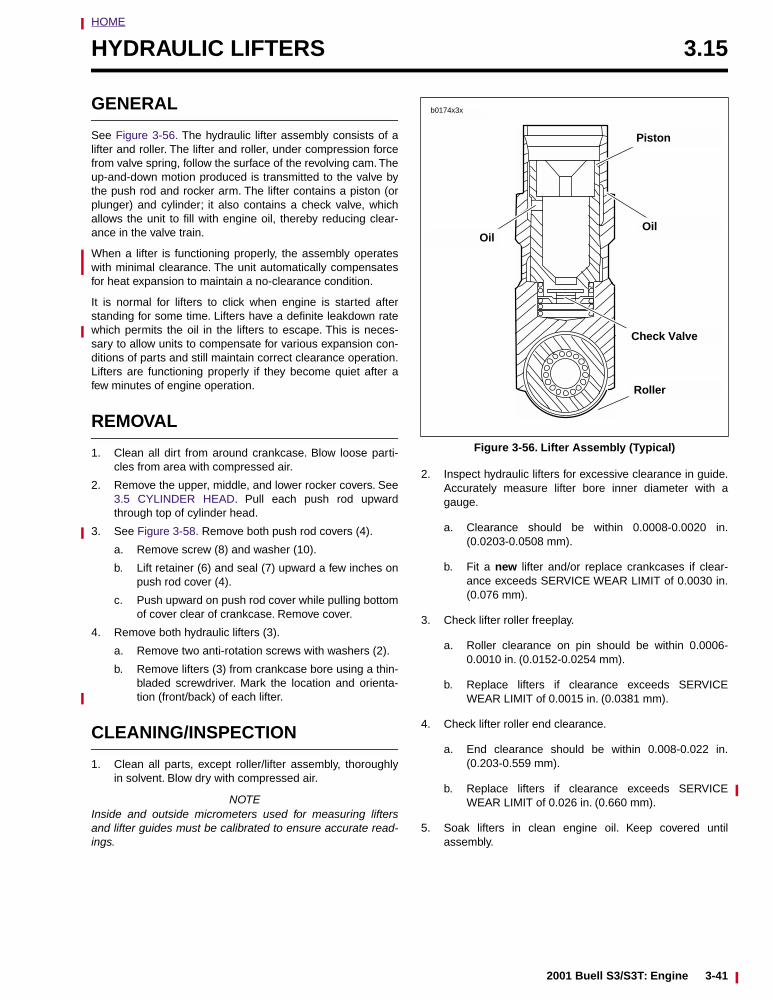
HOME
HYDRAULIC LIFTERS 3.15
GENERAL
See Figure 3-56. The hydraulic lifter assembly consists of alifter and roller. The lifter and roller, under compression forcefrom valve spring, follow the surface of the revolving cam. Theup-and-down motion produced is transmitted to the valve bythe push rod and rocker arm. The lifter contains a piston (orplunger) and cylinder; it also contains a check valve, whichallows the unit to fill with engine oil, thereby reducing clear-ance in the valve train.
When a lifter is functioning properly, the assembly operateswith minimal clearance. The unit automatically compensatesfor heat expansion to maintain a no-clearance condition.
It is normal for lifters to click when engine is started afterstanding for some time. Lifters have a definite leakdown ratewhich permits the oil in the lifters to escape. This is neces-sary to allow units to compensate for various expansion con-ditions of parts and still maintain correct clearance operation.Lifters are functioning properly if they become quiet after afew minutes of engine operation.
REMOVAL
1. Clean all dirt from around crankcase. Blow loose parti-cles from area with compressed air.
2. Remove the upper, middle, and lower rocker covers. See3.5 CYLINDER HEAD. Pull each push rod upwardthrough top of cylinder head.
3. See Figure 3-58. Remove both push rod covers (4).
a. Remove screw (8) and washer (10).
b. Lift retainer (6) and seal (7) upward a few inches onpush rod cover (4).
c. Push upward on push rod cover while pulling bottomof cover clear of crankcase. Remove cover.
4. Remove both hydraulic lifters (3).
a. Remove two anti-rotation screws with washers (2).
b. Remove lifters (3) from crankcase bore using a thin-bladed screwdriver. Mark the location and orienta-tion (front/back) of each lifter.
CLEANING/INSPECTION
1. Clean all parts, except roller/lifter assembly, thoroughlyin solvent. Blow dry with compressed air.
NOTEInside and outside micrometers used for measuring liftersand lifter guides must be calibrated to ensure accurate read-ings.
2. Inspect hydraulic lifters for excessive clearance in guide.Accurately measure lifter bore inner diameter with agauge.
a. Clearance should be within 0.0008-0.0020 in.(0.0203-0.0508 mm).
b. Fit a new lifter and/or replace crankcases if clear-ance exceeds SERVICE WEAR LIMIT of 0.0030 in.(0.076 mm).
3. Check lifter roller freeplay.
a. Roller clearance on pin should be within 0.0006-0.0010 in. (0.0152-0.0254 mm).
b. Replace lifters if clearance exceeds SERVICEWEAR LIMIT of 0.0015 in. (0.0381 mm).
4. Check lifter roller end clearance.
a. End clearance should be within 0.008-0.022 in.(0.203-0.559 mm).
b. Replace lifters if clearance exceeds SERVICEWEAR LIMIT of 0.026 in. (0.660 mm).
5. Soak lifters in clean engine oil. Keep covered untilassembly.
Figure 3-56. Lifter Assembly (Typical)
b0174x3x
Piston
Oil
Check Valve
Oil
Roller
2001 Buell S3/S3T: Engine 3-41
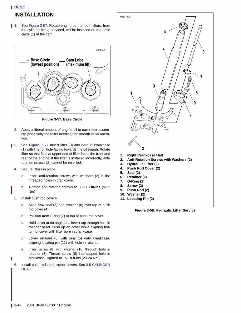
HOME
INSTALLATION
1. See Figure 3-57. Rotate engine so that both lifters, fromthe cylinder being serviced, will be installed on the basecircle (1) of the cam.
2. Apply a liberal amount of engine oil to each lifter assem-bly (especially the roller needles) for smooth initial opera-tion.
3. See Figure 3-58. Insert lifter (3) into bore in crankcase(1) with lifter oil hole facing towards the oil trough. Rotatelifter so that flats at upper end of lifter faces the front andrear of the engine. If the lifter is installed incorrectly, anti-rotation screws (2) cannot be inserted.
4. Secure lifters in place.
a. Insert anti-rotation screws with washers (2) in thethreaded holes in crankcase.
b. Tighten anti-rotation screws to 80-110 in-lbs (9-12Nm)
5. Install push rod covers.
a. Slide new seal (5) and retainer (6) over top of pushrod cover (4).
b. Position new O-ring (7) at top of push rod cover.
c. Hold cover at an angle and insert top through hole incylinder head. Push up on cover while aligning bot-tom of cover with lifter bore in crankcase.
d. Lower retainer (6) with seal (5) onto crankcase,aligning locating pin (11) with hole in retainer.
e. Insert screw (8) with washer (10) through hole inretainer (6). Thread screw (8) into tapped hole incrankcase. Tighten to 15-18 ft-lbs (20-24 Nm).
6. Install push rods and rocker covers. See 3.5 CYLINDERHEAD.
Figure 3-57. Base Circle
15-1
15-1
15-1
15-1
Base Circle(lowest position)
Cam Lobe(maximum lift)
b0509a3x
Figure 3-58. Hydraulic Lifter Service
1. Right Crankcase Half2. Anti-Rotation Screws with Washers (2)3. Hydraulic Lifter (2)4. Push Rod Cover (2)5. Seal (2)6. Retainer (2)7. O-Ring (2)8. Screw (2)9. Push Rod (2)10. Washer (2)11. Locating Pin (2)
b0134a3x
3
4
1
2
6
10
11
8
5
9
7
3-42 2001 Buell S3/S3T: Engine
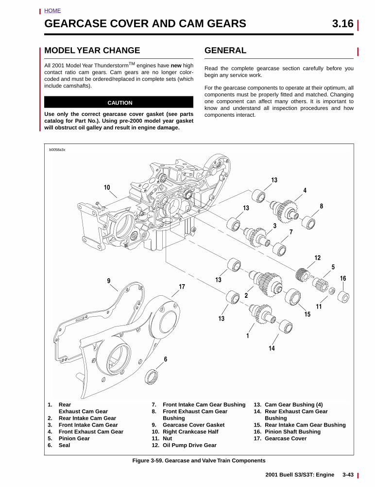
HOME
GEARCASE COVER AND CAM GEARS 3.16
MODEL YEAR CHANGE
All 2001 Model Year ThunderstormTM engines have new highcontact ratio cam gears. Cam gears are no longer color-coded and must be ordered/replaced in complete sets (whichinclude camshafts).
CAUTION
Use only the correct gearcase cover gasket (see partscatalog for Part No.). Using pre-2000 model year gasketwill obstruct oil galley and result in engine damage.
GENERAL
Read the complete gearcase section carefully before youbegin any service work.
For the gearcase components to operate at their optimum, allcomponents must be properly fitted and matched. Changingone component can affect many others. It is important toknow and understand all inspection procedures and howcomponents interact.
Figure 3-59. Gearcase and Valve Train Components
1. Rear Exhaust Cam Gear
2. Rear Intake Cam Gear3. Front Intake Cam Gear4. Front Exhaust Cam Gear5. Pinion Gear6. Seal
7. Front Intake Cam Gear Bushing8. Front Exhaust Cam Gear
Bushing9. Gearcase Cover Gasket10. Right Crankcase Half11. Nut12. Oil Pump Drive Gear
13. Cam Gear Bushing (4)14. Rear Exhaust Cam Gear
Bushing15. Rear Intake Cam Gear Bushing16. Pinion Shaft Bushing17. Gearcase Cover
14
1
13
13
2
15
3
4
13
7
8
13
125
16
11
10
917
6
b0058a3x
2001 Buell S3/S3T: Engine 3-43
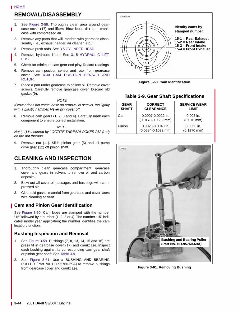
HOME
REMOVAL/DISASSEMBLY
1. See Figure 3-59. Thoroughly clean area around gear-case cover (17) and lifters. Blow loose dirt from crank-case with compressed air.
2. Remove any parts that will interfere with gearcase disas-sembly (i.e., exhaust header, air cleaner, etc.).
3. Remove push rods. See 3.5 CYLINDER HEAD.
4. Remove hydraulic lifters. See 3.15 HYDRAULIC LIFT-ERS.
5. Check for minimum cam gear end play. Record readings.
6. Remove cam position sensor and rotor from gearcasecover. See 4.30 CAM POSITION SENSOR ANDROTOR.
7. Place a pan under gearcase to collect oil. Remove coverscrews. Carefully remove gearcase cover. Discard oldgasket (9).
NOTEIf cover does not come loose on removal of screws, tap lightlywith a plastic hammer. Never pry cover off.
8. Remove cam gears (1, 2, 3 and 4). Carefully mark eachcomponent to ensure correct installation.
NOTENut (11) is secured by LOCTITE THREADLOCKER 262 (red)on the nut threads.
9. Remove nut (11). Slide pinion gear (5) and oil pumpdrive gear (12) off pinion shaft.
CLEANING AND INSPECTION
1. Thoroughly clean gearcase compartment, gearcasecover and gears in solvent to remove oil and carbondeposits.
2. Blow out all cover oil passages and bushings with com-pressed air.
3. Clean old gasket material from gearcase and cover faceswith cleaning solvent.
Cam and Pinion Gear IdentificationSee Figure 3-60. Cam lobes are stamped with the number“15” followed by a number (1, 2, 3 or 4). The number “15” indi-cates model year application; the number identifies the camlocation/function.
Bushing Inspection and Removal1. See Figure 3-59. Bushings (7, 8, 13, 14, 15 and 16) are
press fit in gearcase cover (17) and crankcase. Inspecteach bushing against its corresponding cam gear shaftor pinion gear shaft. See Table 3-9.
2. See Figure 3-61. Use a BUSHING AND BEARINGPULLER (Part No. HD-95760-69A) to remove bushingsfrom gearcase cover and crankcase.
Figure 3-60. Cam Identification
Table 3-9. Gear Shaft Specifications
GEAR SHAFT
CORRECT CLEARANCE
SERVICE WEAR LIMIT
Cam 0.0007-0.0022 in.(0.0178-0.0559 mm)
0.003 in.(0.076 mm)
Pinion 0.0023-0.0043 in.(0.0584-0.1092 mm)
0.0050 in.(0.1270 mm)
Figure 3-61. Removing Bushing
Identify cams by stamped number
b0096a3x
15-1 = Rear Exhaust15-2 = Rear Intake15-3 = Front Intake15-4 = Front Exhaust
Bushing and Bearing Puller (Part No. HD-95760-69A)
2806a
3-44 2001 Buell S3/S3T: Engine
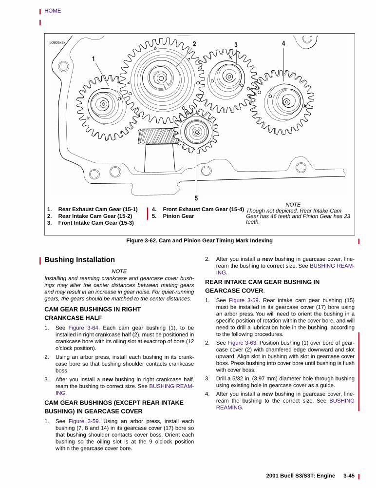
HOME
Bushing Installation
NOTEInstalling and reaming crankcase and gearcase cover bush-ings may alter the center distances between mating gearsand may result in an increase in gear noise. For quiet-runninggears, the gears should be matched to the center distances.
CAM GEAR BUSHINGS IN RIGHT CRANKCASE HALF
1. See Figure 3-64. Each cam gear bushing (1), to beinstalled in right crankcase half (2), must be positioned incrankcase bore with its oiling slot at exact top of bore (12o’clock position).
2. Using an arbor press, install each bushing in its crank-case bore so that bushing shoulder contacts crankcaseboss.
3. After you install a new bushing in right crankcase half,ream the bushing to correct size. See BUSHING REAM-ING.
CAM GEAR BUSHINGS (EXCEPT REAR INTAKE BUSHING) IN GEARCASE COVER
1. See Figure 3-59. Using an arbor press, install eachbushing (7, 8 and 14) in its gearcase cover (17) bore sothat bushing shoulder contacts cover boss. Orient eachbushing so the oiling slot is at the 9 o’clock positionwithin the gearcase cover bore.
2. After you install a new bushing in gearcase cover, line-ream the bushing to correct size. See BUSHING REAM-ING.
REAR INTAKE CAM GEAR BUSHING IN GEARCASE COVER.
1. See Figure 3-59. Rear intake cam gear bushing (15)must be installed in its gearcase cover (17) bore usingan arbor press. You will need to orient the bushing in aspecific position of rotation within the cover bore, and willneed to drill a lubrication hole in the bushing, accordingto the following procedures.
2. See Figure 3-63. Position bushing (1) over bore of gear-case cover (2) with chamfered edge downward and slotupward. Align slot in bushing with slot in gearcase coverboss. Press bushing into cover bore until bushing is flushwith cover boss.
3. Drill a 5/32 in. (3.97 mm) diameter hole through bushingusing existing hole in gearcase cover as a guide.
4. After you install a new bushing in gearcase cover, line-ream the bushing to the correct size. See BUSHINGREAMING.
Figure 3-62. Cam and Pinion Gear Timing Mark Indexing
1. Rear Exhaust Cam Gear (15-1)2. Rear Intake Cam Gear (15-2)3. Front Intake Cam Gear (15-3)
4. Front Exhaust Cam Gear (15-4)5. Pinion Gear
1
2 3 4
5
b0806x3x
NOTEThough not depicted, Rear Intake CamGear has 46 teeth and Pinion Gear has 23 teeth.
2001 Buell S3/S3T: Engine 3-45
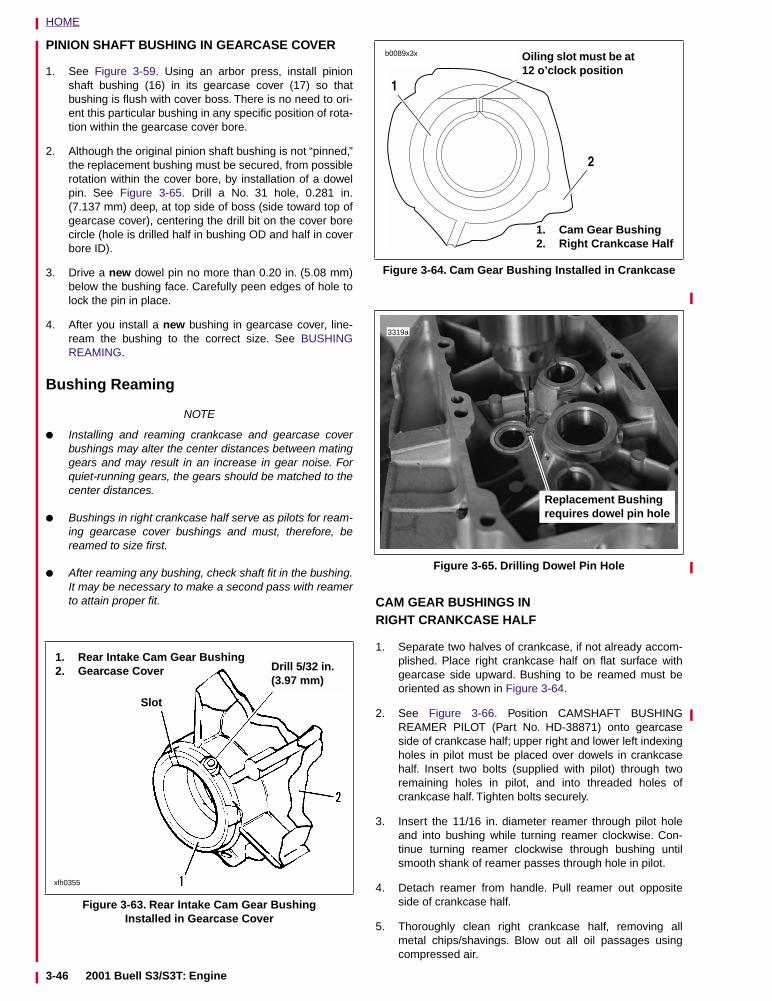
HOME
PINION SHAFT BUSHING IN GEARCASE COVER
1. See Figure 3-59. Using an arbor press, install pinionshaft bushing (16) in its gearcase cover (17) so thatbushing is flush with cover boss. There is no need to ori-ent this particular bushing in any specific position of rota-tion within the gearcase cover bore.
2. Although the original pinion shaft bushing is not “pinned,”the replacement bushing must be secured, from possiblerotation within the cover bore, by installation of a dowelpin. See Figure 3-65. Drill a No. 31 hole, 0.281 in.(7.137 mm) deep, at top side of boss (side toward top ofgearcase cover), centering the drill bit on the cover borecircle (hole is drilled half in bushing OD and half in coverbore ID).
3. Drive a new dowel pin no more than 0.20 in. (5.08 mm)below the bushing face. Carefully peen edges of hole tolock the pin in place.
4. After you install a new bushing in gearcase cover, line-ream the bushing to the correct size. See BUSHINGREAMING.
Bushing Reaming
NOTE
● Installing and reaming crankcase and gearcase coverbushings may alter the center distances between matinggears and may result in an increase in gear noise. Forquiet-running gears, the gears should be matched to thecenter distances.
● Bushings in right crankcase half serve as pilots for ream-ing gearcase cover bushings and must, therefore, bereamed to size first.
● After reaming any bushing, check shaft fit in the bushing.It may be necessary to make a second pass with reamerto attain proper fit. CAM GEAR BUSHINGS IN
RIGHT CRANKCASE HALF
1. Separate two halves of crankcase, if not already accom-plished. Place right crankcase half on flat surface withgearcase side upward. Bushing to be reamed must beoriented as shown in Figure 3-64.
2. See Figure 3-66. Position CAMSHAFT BUSHINGREAMER PILOT (Part No. HD-38871) onto gearcaseside of crankcase half; upper right and lower left indexingholes in pilot must be placed over dowels in crankcasehalf. Insert two bolts (supplied with pilot) through tworemaining holes in pilot, and into threaded holes ofcrankcase half. Tighten bolts securely.
3. Insert the 11/16 in. diameter reamer through pilot holeand into bushing while turning reamer clockwise. Con-tinue turning reamer clockwise through bushing untilsmooth shank of reamer passes through hole in pilot.
4. Detach reamer from handle. Pull reamer out oppositeside of crankcase half.
5. Thoroughly clean right crankcase half, removing allmetal chips/shavings. Blow out all oil passages usingcompressed air.
Figure 3-63. Rear Intake Cam Gear Bushing Installed in Gearcase Cover
Slot
Drill 5/32 in.(3.97 mm)
1. Rear Intake Cam Gear Bushing2. Gearcase Cover
xlh0355
Figure 3-64. Cam Gear Bushing Installed in Crankcase
Figure 3-65. Drilling Dowel Pin Hole
1. Cam Gear Bushing2. Right Crankcase Half
Oiling slot must be at 12 o’clock position
b0089x3x
1
2
Replacement Bushing requires dowel pin hole
3319a
3-46 2001 Buell S3/S3T: Engine
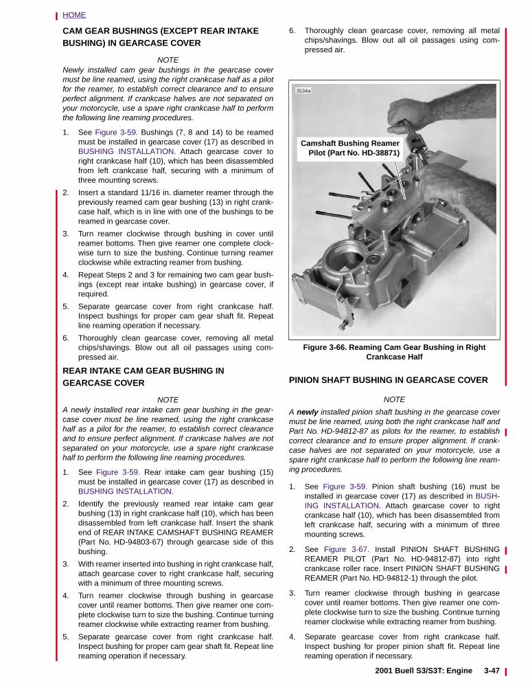
HOME
CAM GEAR BUSHINGS (EXCEPT REAR INTAKE BUSHING) IN GEARCASE COVER
NOTENewly installed cam gear bushings in the gearcase covermust be line reamed, using the right crankcase half as a pilotfor the reamer, to establish correct clearance and to ensureperfect alignment. If crankcase halves are not separated onyour motorcycle, use a spare right crankcase half to performthe following line reaming procedures.
1. See Figure 3-59. Bushings (7, 8 and 14) to be reamedmust be installed in gearcase cover (17) as described inBUSHING INSTALLATION. Attach gearcase cover toright crankcase half (10), which has been disassembledfrom left crankcase half, securing with a minimum ofthree mounting screws.
2. Insert a standard 11/16 in. diameter reamer through thepreviously reamed cam gear bushing (13) in right crank-case half, which is in line with one of the bushings to bereamed in gearcase cover.
3. Turn reamer clockwise through bushing in cover untilreamer bottoms. Then give reamer one complete clock-wise turn to size the bushing. Continue turning reamerclockwise while extracting reamer from bushing.
4. Repeat Steps 2 and 3 for remaining two cam gear bush-ings (except rear intake bushing) in gearcase cover, ifrequired.
5. Separate gearcase cover from right crankcase half.Inspect bushings for proper cam gear shaft fit. Repeatline reaming operation if necessary.
6. Thoroughly clean gearcase cover, removing all metalchips/shavings. Blow out all oil passages using com-pressed air.
REAR INTAKE CAM GEAR BUSHING IN GEARCASE COVER
NOTEA newly installed rear intake cam gear bushing in the gear-case cover must be line reamed, using the right crankcasehalf as a pilot for the reamer, to establish correct clearanceand to ensure perfect alignment. If crankcase halves are notseparated on your motorcycle, use a spare right crankcasehalf to perform the following line reaming procedures.
1. See Figure 3-59. Rear intake cam gear bushing (15)must be installed in gearcase cover (17) as described inBUSHING INSTALLATION.
2. Identify the previously reamed rear intake cam gearbushing (13) in right crankcase half (10), which has beendisassembled from left crankcase half. Insert the shankend of REAR INTAKE CAMSHAFT BUSHING REAMER(Part No. HD-94803-67) through gearcase side of thisbushing.
3. With reamer inserted into bushing in right crankcase half,attach gearcase cover to right crankcase half, securingwith a minimum of three mounting screws.
4. Turn reamer clockwise through bushing in gearcasecover until reamer bottoms. Then give reamer one com-plete clockwise turn to size the bushing. Continue turningreamer clockwise while extracting reamer from bushing.
5. Separate gearcase cover from right crankcase half.Inspect bushing for proper cam gear shaft fit. Repeat linereaming operation if necessary.
6. Thoroughly clean gearcase cover, removing all metalchips/shavings. Blow out all oil passages using com-pressed air.
PINION SHAFT BUSHING IN GEARCASE COVER
NOTE
A newly installed pinion shaft bushing in the gearcase covermust be line reamed, using both the right crankcase half andPart No. HD-94812-87 as pilots for the reamer, to establishcorrect clearance and to ensure proper alignment. If crank-case halves are not separated on your motorcycle, use aspare right crankcase half to perform the following line ream-ing procedures.
1. See Figure 3-59. Pinion shaft bushing (16) must beinstalled in gearcase cover (17) as described in BUSH-ING INSTALLATION. Attach gearcase cover to rightcrankcase half (10), which has been disassembled fromleft crankcase half, securing with a minimum of threemounting screws.
2. See Figure 3-67. Install PINION SHAFT BUSHINGREAMER PILOT (Part No. HD-94812-87) into rightcrankcase roller race. Insert PINION SHAFT BUSHINGREAMER (Part No. HD-94812-1) through the pilot.
3. Turn reamer clockwise through bushing in gearcasecover until reamer bottoms. Then give reamer one com-plete clockwise turn to size the bushing. Continue turningreamer clockwise while extracting reamer from bushing.
4. Separate gearcase cover from right crankcase half.Inspect bushing for proper pinion shaft fit. Repeat linereaming operation if necessary.
Figure 3-66. Reaming Cam Gear Bushing in RightCrankcase Half
Camshaft Bushing ReamerPilot (Part No. HD-38871)
3534a
2001 Buell S3/S3T: Engine 3-47
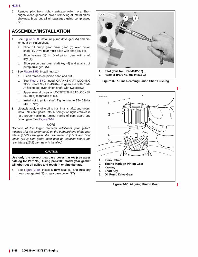
HOME
5. Remove pilot from right crankcase roller race. Thor-oughly clean gearcase cover, removing all metal chips/shavings. Blow out all oil passages using compressedair.
ASSEMBLY/INSTALLATION
1. See Figure 3-68. Install oil pump drive gear (5) and pin-ion gear on pinion shaft.
a. Slide oil pump gear drive gear (5) over pinionshaft (1). Drive gear must align with shaft key (4).
b. Align keyway (3) in ID of pinion gear with shaftkey (4).
c. Slide pinion gear over shaft key (4) and against oilpump drive gear (5).
2. See Figure 3-59. Install nut (11).
a. Clean threads on pinion shaft and nut.
b. See Figure 3-69. Install CRANKSHAFT LOCKINGTOOL (Part No. HD-43984) to gearcase with “SideA” facing out, over pinion shaft, with two screws.
c. Apply several drops of LOCTITE THREADLOCKER262 (red) to threads of nut.
d. Install nut to pinion shaft. Tighten nut to 35-45 ft-lbs(48-61 Nm).
3. Liberally apply engine oil to bushings, shafts, and gears.Install all cam gears into bushings of right crankcasehalf, properly aligning timing marks of cam gears andpinion gear. See Figure 3-62.
NOTEBecause of the larger diameter additional gear (whichmeshes with the pinion gear) on the outboard end of the rearintake (15-2) cam gear, the rear exhaust (15-1) and frontintake (15-3) cam gears must both be installed before therear intake (15-2) cam gear is installed.
CAUTION
Use only the correct gearcase cover gasket (see partscatalog for Part No.). Using pre-2000 model year gasketwill obstruct oil galley and result in engine damage.
4. See Figure 3-59. Install a new seal (6) and new drygearcover gasket (9) on gearcase cover (17).
Figure 3-67. Line Reaming Pinion Shaft Bushing
Figure 3-68. Aligning Pinion Gear
3545a
1. Pilot (Part No. HD-94812-87)2. Reamer (Part No. HD-94812-1)
21
b0342x3x
1
2
3
45
1. Pinion Shaft2. Timing Mark on Pinion Gear3. Keyway4. Shaft Key5. Oil Pump Drive Gear
3-48 2001 Buell S3/S3T: Engine
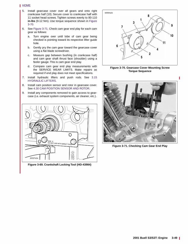
HOME
5. Install gearcase cover over all gears and onto rightcrankcase half (10). Secure cover to crankcase half with11 socket head screws. Tighten screws evenly to 80-110in-lbs (9-12 Nm). Use torque sequence shown in Figure3-70.
6. See Figure 3-71. Check cam gear end play for each camgear as follows:
a. Turn engine over until lobe of cam gear beingchecked is pointing toward its respective lifter guidehole.
b. Gently pry the cam gear toward the gearcase coverusing a flat blade screwdriver.
c. Measure gap between bushing (in crankcase half)and cam gear shaft thrust face (shoulder) using afeeler gauge. This is cam gear end play.
d. Compare cam gear end play measurements withthe SERVICE WEAR LIMITS. Make repairs asrequired if end play does not meet specifications.
7. Install hydraulic lifters and push rods. See 3.15HYDRAULIC LIFTERS.
8. Install cam position sensor and rotor in gearcase cover.See 4.30 CAM POSITION SENSOR AND ROTOR.
9. Install any components removed to gain access to gear-case (i.e. exhaust system components, air cleaner, etc.).
Figure 3-69. Crankshaft Locking Tool (HD-43984)
b0337a3x
Figure 3-70. Gearcase Cover Mounting ScrewTorque Sequence
Figure 3-71. Checking Cam Gear End Play
b0064a3x
73
1
11
10
9
42
5
6
8
7988
2001 Buell S3/S3T: Engine 3-49
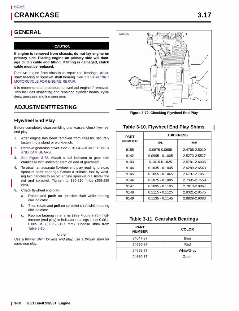
HOME
CRANKCASE 3.17
GENERAL
CAUTION
If engine is removed from chassis, do not lay engine onprimary side. Placing engine on primary side will dam-age clutch cable end fitting. If fitting is damaged, clutchcable must be replaced.
Remove engine from chassis to repair rod bearings, pinionshaft bearing or sprocket shaft bearing. See 3.3 STRIPPINGMOTORCYCLE FOR ENGINE REPAIR.
It is recommended procedure to overhaul engine if removed.This includes inspecting and repairing cylinder heads, cylin-ders, gearcase and transmission.
ADJUSTMENT/TESTING
Flywheel End PlayBefore completely disassembling crankcases, check flywheelend play.
1. After engine has been removed from chassis, securelyfasten it to a stand or workbench.
2. Remove gearcase cover. See 3.16 GEARCASE COVERAND CAM GEARS.
3. See Figure 3-72. Attach a dial indicator to gear sidecrankcase with indicator stem on end of gearshaft.
4. To obtain an accurate flywheel end play reading, preloadsprocket shaft bearings. Create a suitable tool by weld-ing two handles to an old engine sprocket nut. Install thenut and sprocket. Tighten to 190-210 ft-lbs (258-285Nm).
5. Check flywheel end play.
a. Rotate and push on sprocket shaft while readingdial indicator.
b. Then rotate and pull on sprocket shaft while readingdial indicator.
c. Replace bearing inner shim (See Figure 3-75.) if dif-ference (end play) in indicator readings is not 0.001-0.005 in. (0.025-0.127 mm). Choose shim fromTable 3-10.
NOTEUse a thinner shim for less end play; use a thicker shim formore end play.
Figure 3-72. Checking Flywheel End Play
Table 3-10. Flywheel End Play Shims
PARTNUMBER
THICKNESS
IN. MM
9155 0.0975-0.0985 2.4765-2.5019
9142 0.0995 - 0.1005 2.5273-2.5527
9143 0.1015-0.1025 2.5781-2.6035
9144 0.1035 - 0.1045 2.6289-2.6543
9145 0.1055 - 0.1065 2.6797-2.7051
9146 0.1075 - 0.1085 2.7305-2.7559
9147 0.1095 - 0.1105 2.7813-2.8067
9148 0.1115 - 0.1125 2.8321-2.8575
9149 0.1135 - 0.1145 2.8829-2.9083
Table 3-11. Gearshaft Bearings
PARTNUMBER
COLOR
24647-87 Blue
24650-87 Red
24659-87 White/Grey
24660-87 Green
b0292x3x
3-50 2001 Buell S3/S3T: Engine
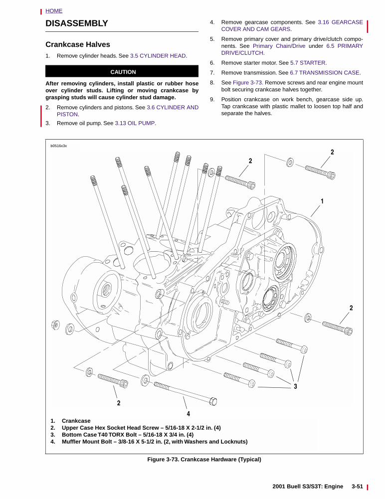
HOME
DISASSEMBLY
Crankcase Halves1. Remove cylinder heads. See 3.5 CYLINDER HEAD.
CAUTION
After removing cylinders, install plastic or rubber hoseover cylinder studs. Lifting or moving crankcase bygrasping studs will cause cylinder stud damage.
2. Remove cylinders and pistons. See 3.6 CYLINDER ANDPISTON.
3. Remove oil pump. See 3.13 OIL PUMP.
4. Remove gearcase components. See 3.16 GEARCASECOVER AND CAM GEARS.
5. Remove primary cover and primary drive/clutch compo-nents. See Primary Chain/Drive under 6.5 PRIMARYDRIVE/CLUTCH.
6. Remove starter motor. See 5.7 STARTER.
7. Remove transmission. See 6.7 TRANSMISSION CASE.
8. See Figure 3-73. Remove screws and rear engine mountbolt securing crankcase halves together.
9. Position crankcase on work bench, gearcase side up.Tap crankcase with plastic mallet to loosen top half andseparate the halves.
Figure 3-73. Crankcase Hardware (Typical)
1. Crankcase2. Upper Case Hex Socket Head Screw – 5/16-18 X 2-1/2 in. (4)3. Bottom Case T40 TORX Bolt – 5/16-18 X 3/4 in. (4)4. Muffler Mount Bolt – 3/8-16 X 5-1/2 in. (2, with Washers and Locknuts)
b0516x3x
22
1
2
2
4
3
2001 Buell S3/S3T: Engine 3-51
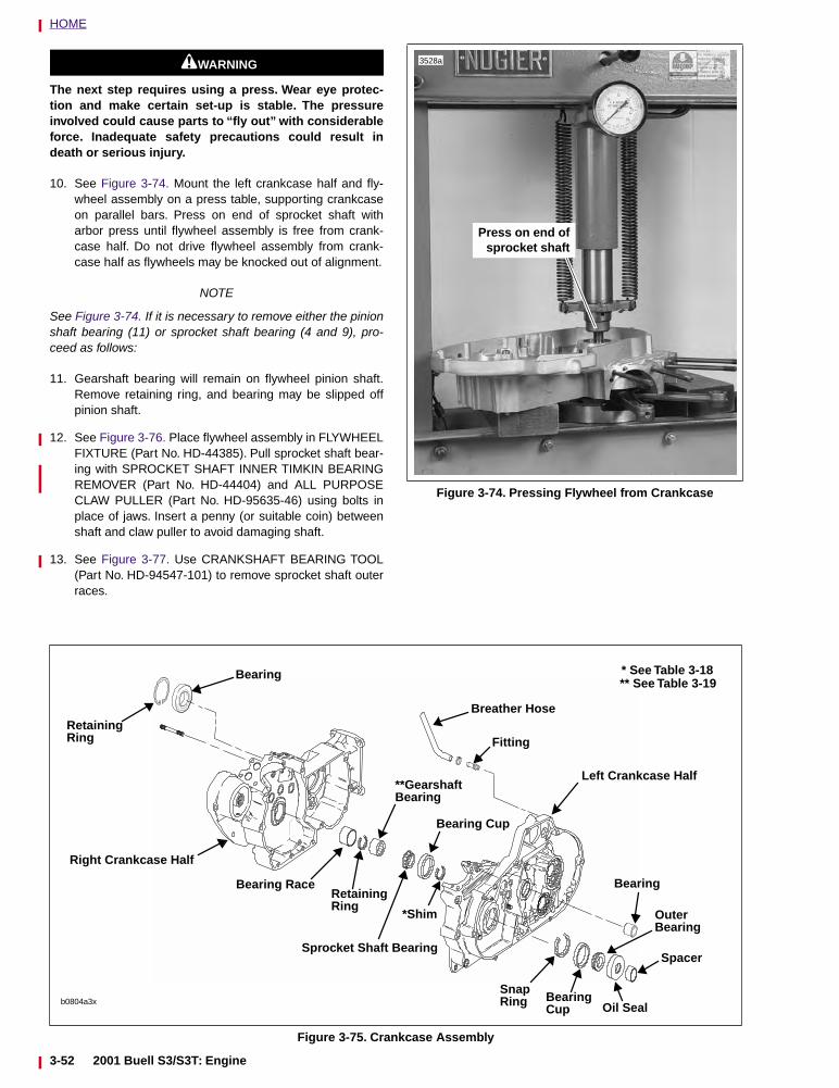
HOME
11WARNING1WARNING
The next step requires using a press. Wear eye protec-tion and make certain set-up is stable. The pressureinvolved could cause parts to “fly out” with considerableforce. Inadequate safety precautions could result indeath or serious injury.
10. See Figure 3-74. Mount the left crankcase half and fly-wheel assembly on a press table, supporting crankcaseon parallel bars. Press on end of sprocket shaft witharbor press until flywheel assembly is free from crank-case half. Do not drive flywheel assembly from crank-case half as flywheels may be knocked out of alignment.
NOTE
See Figure 3-74. If it is necessary to remove either the pinionshaft bearing (11) or sprocket shaft bearing (4 and 9), pro-ceed as follows:
11. Gearshaft bearing will remain on flywheel pinion shaft.Remove retaining ring, and bearing may be slipped offpinion shaft.
12. See Figure 3-76. Place flywheel assembly in FLYWHEELFIXTURE (Part No. HD-44385). Pull sprocket shaft bear-ing with SPROCKET SHAFT INNER TIMKIN BEARINGREMOVER (Part No. HD-44404) and ALL PURPOSECLAW PULLER (Part No. HD-95635-46) using bolts inplace of jaws. Insert a penny (or suitable coin) betweenshaft and claw puller to avoid damaging shaft.
13. See Figure 3-77. Use CRANKSHAFT BEARING TOOL(Part No. HD-94547-101) to remove sprocket shaft outerraces.
Figure 3-74. Pressing Flywheel from Crankcase
Press on end ofsprocket shaft
3528a
Figure 3-75. Crankcase Assembly
b0804a3x
Fitting
Breather Hose
Left Crankcase Half
Right Crankcase Half
RetainingRing
Bearing
Bearing
Outer
BearingOil Seal
SnapRing
*Shim
Bearing Cup
Sprocket Shaft Bearing
**GearshaftBearing
RetainingRing
Bearing Race
* See Table 3-18** See Table 3-19
Spacer
Bearing
Cup
3-52 2001 Buell S3/S3T: Engine
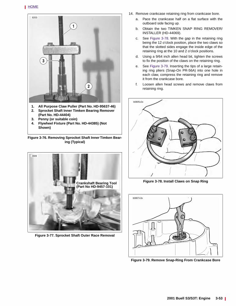
HOME
14. Remove crankcase retaining ring from crankcase bore.
a. Pace the crankcase half on a flat surface with theoutboard side facing up.
b. Obtain the two TIMKEN SNAP RING REMOVER/INSTALLER (HD-44069).
c. See Figure 3-78. With the gap in the retaining ringbeing the 12 o’clock position, place the two claws sothat the slotted sides engage the inside edge of theretaining ring at the 10 and 2 o’clock positions.
d. Using a 9/64 inch allen head bit, tighten the screwsto fix the position of the claws on the retaining ring.
e. See Figure 3-79. Inserting the tips of a large retain-ing ring pliers (Snap-On PR-56A) into one hole ineach claw, compress the retaining ring and removeit from the crankcase bore.
f. Loosen allen head screws and remove claws fromretaining ring.
Figure 3-76. Removing Sprocket Shaft Inner Timken Bear-ing (Typical)
Figure 3-77. Sprocket Shaft Outer Race Removal
8203
1
1. All Purpose Claw Puller (Part No. HD-95637-46)2. Sprocket Shaft Inner Timken Bearing Remover
(Part No. HD-44404)3. Penny (or suitable coin)4. Flywheel Fixture (Part No. HD-44385) (Not
Shown)
2
3
2809
Crankshaft Bearing Tool(Part No HD-9457-101)
Figure 3-78. Install Claws on Snap Ring
Figure 3-79. Remove Snap-Ring From Crankcase Bore
b0805x3x
b0807x3x
2001 Buell S3/S3T: Engine 3-53
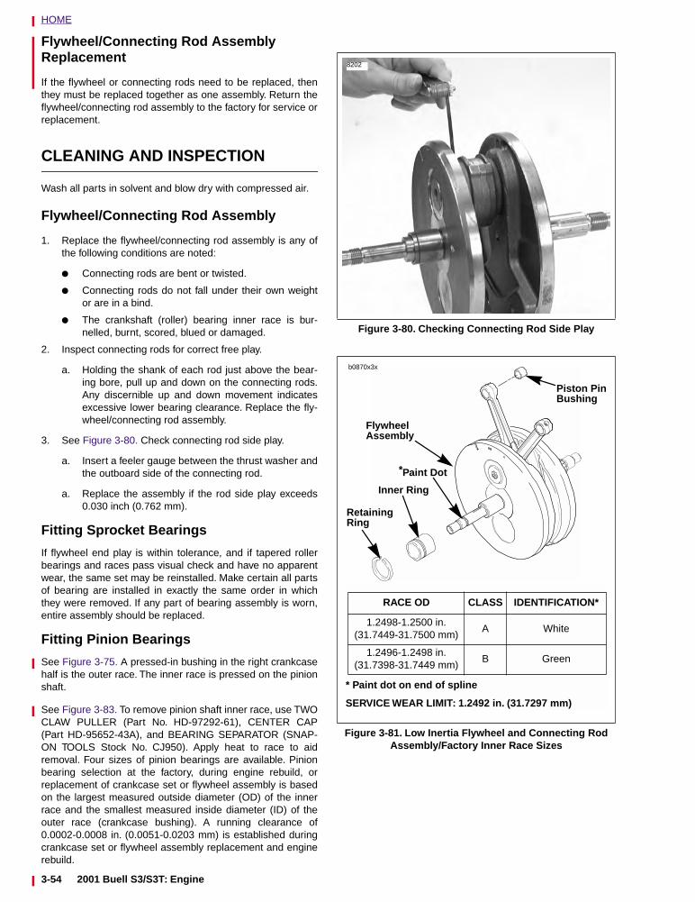
HOME
Flywheel/Connecting Rod Assembly Replacement
If the flywheel or connecting rods need to be replaced, thenthey must be replaced together as one assembly. Return theflywheel/connecting rod assembly to the factory for service orreplacement.
CLEANING AND INSPECTION
Wash all parts in solvent and blow dry with compressed air.
Flywheel/Connecting Rod Assembly
1. Replace the flywheel/connecting rod assembly is any ofthe following conditions are noted:
● Connecting rods are bent or twisted.
● Connecting rods do not fall under their own weightor are in a bind.
● The crankshaft (roller) bearing inner race is bur-nelled, burnt, scored, blued or damaged.
2. Inspect connecting rods for correct free play.
a. Holding the shank of each rod just above the bear-ing bore, pull up and down on the connecting rods.Any discernible up and down movement indicatesexcessive lower bearing clearance. Replace the fly-wheel/connecting rod assembly.
3. See Figure 3-80. Check connecting rod side play.
a. Insert a feeler gauge between the thrust washer andthe outboard side of the connecting rod.
a. Replace the assembly if the rod side play exceeds0.030 inch (0.762 mm).
Fitting Sprocket Bearings
If flywheel end play is within tolerance, and if tapered rollerbearings and races pass visual check and have no apparentwear, the same set may be reinstalled. Make certain all partsof bearing are installed in exactly the same order in whichthey were removed. If any part of bearing assembly is worn,entire assembly should be replaced.
Fitting Pinion Bearings
See Figure 3-75. A pressed-in bushing in the right crankcasehalf is the outer race. The inner race is pressed on the pinionshaft.
See Figure 3-83. To remove pinion shaft inner race, use TWOCLAW PULLER (Part No. HD-97292-61), CENTER CAP(Part HD-95652-43A), and BEARING SEPARATOR (SNAP-ON TOOLS Stock No. CJ950). Apply heat to race to aidremoval. Four sizes of pinion bearings are available. Pinionbearing selection at the factory, during engine rebuild, orreplacement of crankcase set or flywheel assembly is basedon the largest measured outside diameter (OD) of the innerrace and the smallest measured inside diameter (ID) of theouter race (crankcase bushing). A running clearance of0.0002-0.0008 in. (0.0051-0.0203 mm) is established duringcrankcase set or flywheel assembly replacement and enginerebuild.
Figure 3-80. Checking Connecting Rod Side Play
Figure 3-81. Low Inertia Flywheel and Connecting Rod Assembly/Factory Inner Race Sizes
8202
b0870x3x
FlywheelAssembly
Inner Ring
RetainingRing
Piston PinBushing
* Paint dot on end of spline
SERVICE WEAR LIMIT: 1.2492 in. (31.7297 mm)
RACE OD CLASS IDENTIFICATION*
1.2498-1.2500 in.(31.7449-31.7500 mm)
A White
1.2496-1.2498 in.(31.7398-31.7449 mm)
B Green
*Paint Dot
3-54 2001 Buell S3/S3T: Engine
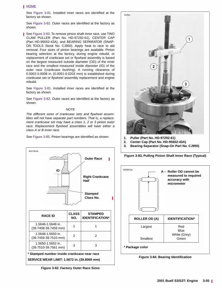
HOME
See Figure 3-81. Installed inner races are identified at thefactory as shown.
See Figure 3-82. Outer races are identified at the factory asshown.
See Figure 3-83. To remove pinion shaft inner race, use TWOCLAW PULLER (Part No. HD-97292-61), CENTER CAP(Part HD-95652-43A), and BEARING SEPARATOR (SNAP-ON TOOLS Stock No. CJ950). Apply heat to race to aidremoval. Four sizes of pinion bearings are available. Pinionbearing selection at the factory, during engine rebuild, orreplacement of crankcase set or flywheel assembly is basedon the largest measured outside diameter (OD) of the innerrace and the smallest measured inside diameter (ID) of theouter race (crankcase bushing). A running clearance of0.0002-0.0008 in. (0.0051-0.0203 mm) is established duringcrankcase set or flywheel assembly replacement and enginerebuild.
See Figure 3-81. Installed inner races are identified at thefactory as shown.
See Figure 3-82. Outer races are identified at the factory asshown.
NOTEThe different sizes of crankcase sets and flywheel assem-blies will not have separate part numbers. That is, a replace-ment crankcase set may have a class 1, 2 or 3 pinion outerrace. Replacement flywheel assemblies will have either aclass A or B inner race.
See Figure 3-85. Pinion bearings are identified as shown.
Figure 3-82. Factory Outer Race Sizes
* Stamped number inside crankcase near race
SERVICE WEAR LIMIT: 1.5672 in. (39.8069 mm)
RACE IDCLASS
NO.STAMPED
IDENTIFICATION*
1.5646-1.5648 in.(39.7408-39.7459 mm)
1 1
1.5648-1.5650 in.(39.7459-39.7510 mm)
2 2
1.5650-1.5652 in.(39.7510-39.7561 mm)
3 3
ID
b0176x3x
Outer Race
Right Crankcase Half
Stamped Class No.
Figure 3-83. Pulling Pinion Shaft Inner Race (Typical)
Figure 3-84. Bearing Identification
1. Puller (Part No. HD-97292-61)2. Center Cap (Part No. HD-95652-43A)3. Bearing Separator (Snap-On Part No. CJ950)
1
3106a
3
2
A – Roller OD cannot be measured to required accuracy with micrometer
* Package color
ROLLER OD (A) IDENTIFICATION*
Largest
Smallest
RedBlue
White (Grey)Green
b0065x3x
2001 Buell S3/S3T: Engine 3-55
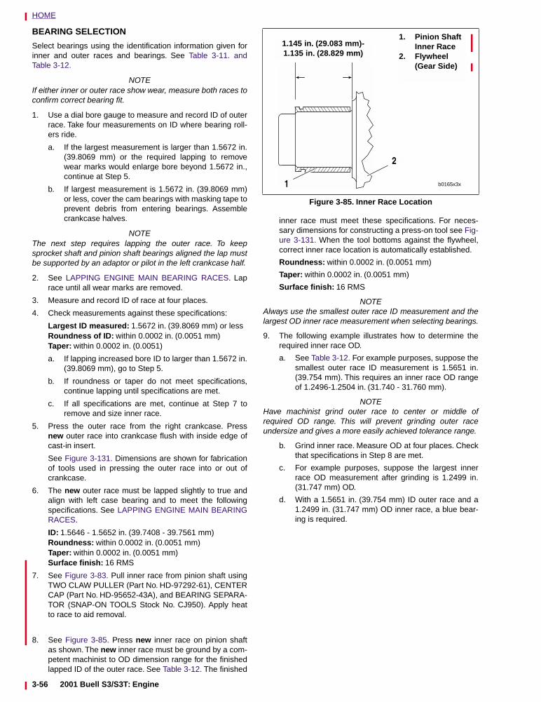
HOME
BEARING SELECTION
Select bearings using the identification information given forinner and outer races and bearings. See Table 3-11. andTable 3-12.
NOTEIf either inner or outer race show wear, measure both races toconfirm correct bearing fit.
1. Use a dial bore gauge to measure and record ID of outerrace. Take four measurements on ID where bearing roll-ers ride.
a. If the largest measurement is larger than 1.5672 in.(39.8069 mm) or the required lapping to removewear marks would enlarge bore beyond 1.5672 in.,continue at Step 5.
b. If largest measurement is 1.5672 in. (39.8069 mm)or less, cover the cam bearings with masking tape toprevent debris from entering bearings. Assemblecrankcase halves.
NOTEThe next step requires lapping the outer race. To keepsprocket shaft and pinion shaft bearings aligned the lap mustbe supported by an adaptor or pilot in the left crankcase half.
2. See LAPPING ENGINE MAIN BEARING RACES. Laprace until all wear marks are removed.
3. Measure and record ID of race at four places.
4. Check measurements against these specifications:
Largest ID measured: 1.5672 in. (39.8069 mm) or lessRoundness of ID: within 0.0002 in. (0.0051 mm)Taper: within 0.0002 in. (0.0051)
a. If lapping increased bore ID to larger than 1.5672 in.(39.8069 mm), go to Step 5.
b. If roundness or taper do not meet specifications,continue lapping until specifications are met.
c. If all specifications are met, continue at Step 7 toremove and size inner race.
5. Press the outer race from the right crankcase. Pressnew outer race into crankcase flush with inside edge ofcast-in insert.
See Figure 3-131. Dimensions are shown for fabricationof tools used in pressing the outer race into or out ofcrankcase.
6. The new outer race must be lapped slightly to true andalign with left case bearing and to meet the followingspecifications. See LAPPING ENGINE MAIN BEARINGRACES.
ID: 1.5646 - 1.5652 in. (39.7408 - 39.7561 mm)Roundness: within 0.0002 in. (0.0051 mm)Taper: within 0.0002 in. (0.0051 mm)Surface finish: 16 RMS
7. See Figure 3-83. Pull inner race from pinion shaft usingTWO CLAW PULLER (Part No. HD-97292-61), CENTERCAP (Part No. HD-95652-43A), and BEARING SEPARA-TOR (SNAP-ON TOOLS Stock No. CJ950). Apply heatto race to aid removal.
8. See Figure 3-85. Press new inner race on pinion shaftas shown. The new inner race must be ground by a com-petent machinist to OD dimension range for the finishedlapped ID of the outer race. See Table 3-12. The finished
inner race must meet these specifications. For neces-sary dimensions for constructing a press-on tool see Fig-ure 3-131. When the tool bottoms against the flywheel,correct inner race location is automatically established.
Roundness: within 0.0002 in. (0.0051 mm)
Taper: within 0.0002 in. (0.0051 mm)
Surface finish: 16 RMS
NOTEAlways use the smallest outer race ID measurement and thelargest OD inner race measurement when selecting bearings.
9. The following example illustrates how to determine therequired inner race OD.
a. See Table 3-12. For example purposes, suppose thesmallest outer race ID measurement is 1.5651 in.(39.754 mm). This requires an inner race OD rangeof 1.2496-1.2504 in. (31.740 - 31.760 mm).
NOTEHave machinist grind outer race to center or middle ofrequired OD range. This will prevent grinding outer raceundersize and gives a more easily achieved tolerance range.
b. Grind inner race. Measure OD at four places. Checkthat specifications in Step 8 are met.
c. For example purposes, suppose the largest innerrace OD measurement after grinding is 1.2499 in.(31.747 mm) OD.
d. With a 1.5651 in. (39.754 mm) ID outer race and a1.2499 in. (31.747 mm) OD inner race, a blue bear-ing is required.
Figure 3-85. Inner Race Location
1.145 in. (29.083 mm)-1.135 in. (28.829 mm)
1. Pinion Shaft Inner Race
2. Flywheel (Gear Side)
b0165x3x1
2
3-56 2001 Buell S3/S3T: Engine
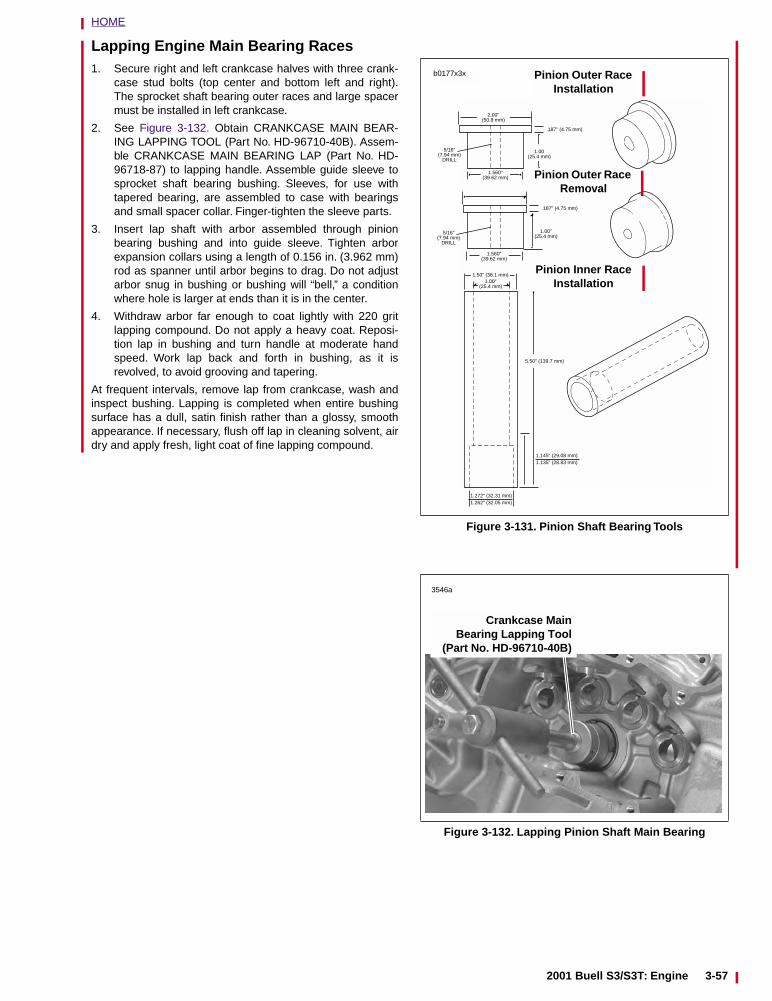
HOME
Lapping Engine Main Bearing Races1. Secure right and left crankcase halves with three crank-
case stud bolts (top center and bottom left and right).The sprocket shaft bearing outer races and large spacermust be installed in left crankcase.
2. See Figure 3-132. Obtain CRANKCASE MAIN BEAR-ING LAPPING TOOL (Part No. HD-96710-40B). Assem-ble CRANKCASE MAIN BEARING LAP (Part No. HD-96718-87) to lapping handle. Assemble guide sleeve tosprocket shaft bearing bushing. Sleeves, for use withtapered bearing, are assembled to case with bearingsand small spacer collar. Finger-tighten the sleeve parts.
3. Insert lap shaft with arbor assembled through pinionbearing bushing and into guide sleeve. Tighten arborexpansion collars using a length of 0.156 in. (3.962 mm)rod as spanner until arbor begins to drag. Do not adjustarbor snug in bushing or bushing will “bell,” a conditionwhere hole is larger at ends than it is in the center.
4. Withdraw arbor far enough to coat lightly with 220 gritlapping compound. Do not apply a heavy coat. Reposi-tion lap in bushing and turn handle at moderate handspeed. Work lap back and forth in bushing, as it isrevolved, to avoid grooving and tapering.
At frequent intervals, remove lap from crankcase, wash andinspect bushing. Lapping is completed when entire bushingsurface has a dull, satin finish rather than a glossy, smoothappearance. If necessary, flush off lap in cleaning solvent, airdry and apply fresh, light coat of fine lapping compound.
Figure 3-131. Pinion Shaft Bearing Tools
Figure 3-132. Lapping Pinion Shaft Main Bearing
Pinion Outer Race Installation
Pinion Outer Race Removal
Pinion Inner Race Installation
.187" (4.75 mm)
2.00"(50.8 mm)
1.00(25.4 mm)
1.00"(25.4 mm)
1.560"(39.62 mm)
1.560"(39.62 mm)
.187" (4.75 mm)
5/16"(7.94 mm)
DRILL
5/16"(7.94 mm)
DRILL
1.00"(25.4 mm)
1.50" (38.1 mm)
1.272" (32.31 mm)1.262" (32.05 mm)
1.145" (29.08 mm)1.135" (28.83 mm)
5.50" (139.7 mm)
b0177x3x
Crankcase MainBearing Lapping Tool
(Part No. HD-96710-40B)
3546a
2001 Buell S3/S3T: Engine 3-57
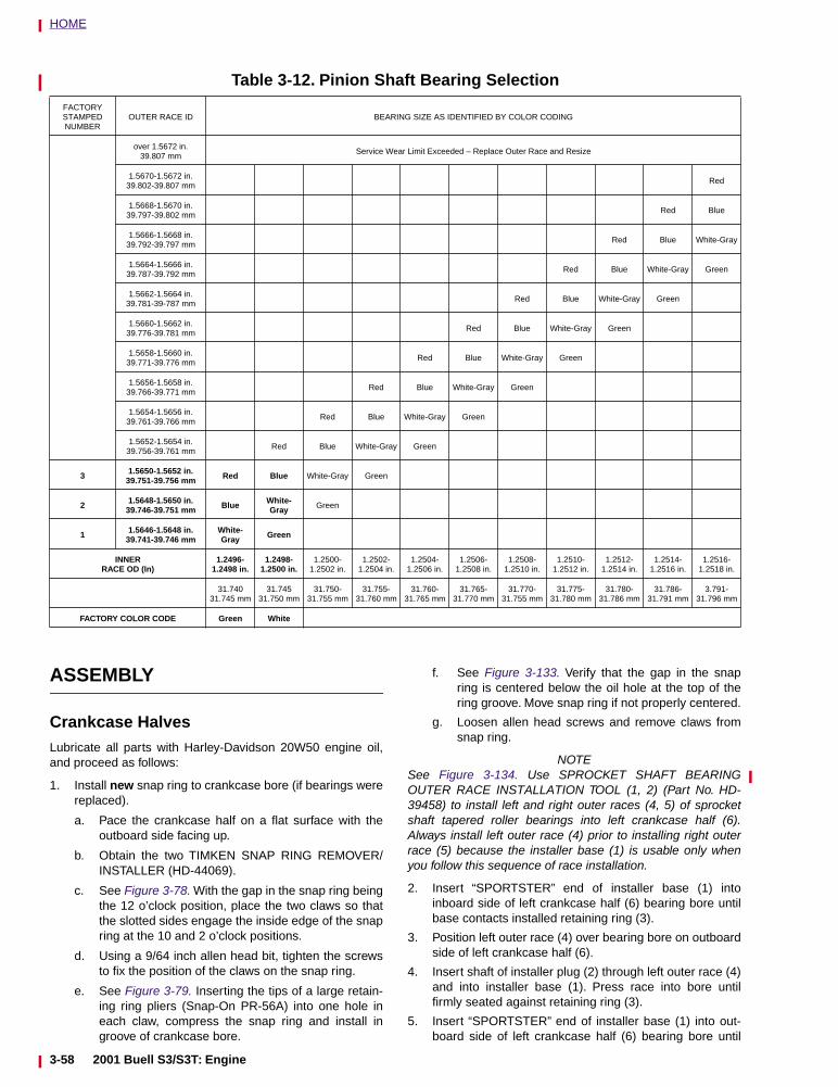
HOME
ASSEMBLY
Crankcase HalvesLubricate all parts with Harley-Davidson 20W50 engine oil,and proceed as follows:
1. Install new snap ring to crankcase bore (if bearings werereplaced).
a. Pace the crankcase half on a flat surface with theoutboard side facing up.
b. Obtain the two TIMKEN SNAP RING REMOVER/INSTALLER (HD-44069).
c. See Figure 3-78. With the gap in the snap ring beingthe 12 o’clock position, place the two claws so thatthe slotted sides engage the inside edge of the snapring at the 10 and 2 o’clock positions.
d. Using a 9/64 inch allen head bit, tighten the screwsto fix the position of the claws on the snap ring.
e. See Figure 3-79. Inserting the tips of a large retain-ing ring pliers (Snap-On PR-56A) into one hole ineach claw, compress the snap ring and install ingroove of crankcase bore.
f. See Figure 3-133. Verify that the gap in the snapring is centered below the oil hole at the top of thering groove. Move snap ring if not properly centered.
g. Loosen allen head screws and remove claws fromsnap ring.
NOTESee Figure 3-134. Use SPROCKET SHAFT BEARINGOUTER RACE INSTALLATION TOOL (1, 2) (Part No. HD-39458) to install left and right outer races (4, 5) of sprocketshaft tapered roller bearings into left crankcase half (6).Always install left outer race (4) prior to installing right outerrace (5) because the installer base (1) is usable only whenyou follow this sequence of race installation.
2. Insert “SPORTSTER” end of installer base (1) intoinboard side of left crankcase half (6) bearing bore untilbase contacts installed retaining ring (3).
3. Position left outer race (4) over bearing bore on outboardside of left crankcase half (6).
4. Insert shaft of installer plug (2) through left outer race (4)and into installer base (1). Press race into bore untilfirmly seated against retaining ring (3).
5. Insert “SPORTSTER” end of installer base (1) into out-board side of left crankcase half (6) bearing bore until
Table 3-12. Pinion Shaft Bearing Selection
FACTORYSTAMPEDNUMBER
OUTER RACE ID BEARING SIZE AS IDENTIFIED BY COLOR CODING
over 1.5672 in.39.807 mm
Service Wear Limit Exceeded – Replace Outer Race and Resize
1.5670-1.5672 in.39.802-39.807 mm
Red
1.5668-1.5670 in.39.797-39.802 mm
Red Blue
1.5666-1.5668 in.39.792-39.797 mm
Red Blue White-Gray
1.5664-1.5666 in.39.787-39.792 mm
Red Blue White-Gray Green
1.5662-1.5664 in.39.781-39-787 mm
Red Blue White-Gray Green
1.5660-1.5662 in.39.776-39.781 mm
Red Blue White-Gray Green
1.5658-1.5660 in.39.771-39.776 mm
Red Blue White-Gray Green
1.5656-1.5658 in.39.766-39.771 mm
Red Blue White-Gray Green
1.5654-1.5656 in.39.761-39.766 mm
Red Blue White-Gray Green
1.5652-1.5654 in.39.756-39.761 mm
Red Blue White-Gray Green
3 1.5650-1.5652 in.39.751-39.756 mm Red Blue White-Gray Green
2 1.5648-1.5650 in.39.746-39.751 mm Blue White-
Gray Green
1 1.5646-1.5648 in.39.741-39.746 mm
White-Gray Green
INNERRACE OD (In)
1.2496-1.2498 in.
1.2498-1.2500 in.
1.2500-1.2502 in.
1.2502-1.2504 in.
1.2504-1.2506 in.
1.2506-1.2508 in.
1.2508-1.2510 in.
1.2510-1.2512 in.
1.2512-1.2514 in.
1.2514-1.2516 in.
1.2516-1.2518 in.
31.740
31.745 mm31.745
31.750 mm31.750-
31.755 mm31.755-
31.760 mm31.760-
31.765 mm31.765-
31.770 mm31.770-
31.755 mm31.775-
31.780 mm31.780-
31.786 mm31.786-
31.791 mm3.791-
31.796 mm
FACTORY COLOR CODE Green White
3-58 2001 Buell S3/S3T: Engine
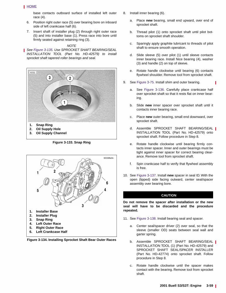
HOME
2001 Buell S3/S3T: Engine 3-59
base contacts outboard surface of installed left outerrace (4).
6. Position right outer race (5) over bearing bore on inboardside of left crankcase half (6).
7. Insert shaft of installer plug (2) through right outer race(5) and into installer base (1). Press race into bore untilfirmly seated against retaining ring (3).
NOTESee Figure 3-135. Use SPROCKET SHAFT BEARING/SEALINSTALLATION TOOL (Part No. HD-42579) to installsprocket shaft tapered roller bearings and seal.
8. Install inner bearing (6).
a. Place new bearing, small end upward, over end ofsprocket shaft.
b. Thread pilot (1) onto sprocket shaft until pilot bot-toms on sprocket shaft shoulder.
c. Sparingly apply graphite lubricant to threads of pilotshaft to ensure smooth operation.
d. Slide sleeve (5) over pilot (1) until sleeve contactsinner bearing race. Install Nice bearing (4), washer(3) and handle (2) on top of sleeve.
e. Rotate handle clockwise until bearing (6) contactsflywheel shoulder. Remove tool from sprocket shaft.
9. See Figure 3-75. Install shim and outer bearing.
a. See Figure 3-136. Carefully place crankcase halfover sprocket shaft so that it rests flat on inner bear-ing.
b. Slide new inner spacer over sprocket shaft until itcontacts inner bearing race.
c. Place new outer bearing, small end downward, oversprocket shaft.
d. Assemble SPROCKET SHAFT BEARING/SEALINSTALLATION TOOL (Part No. HD-42579) ontosprocket shaft. Follow procedure in Step 8.
e. Rotate handle clockwise until bearing firmly con-tacts inner spacer. Inner and outer bearings must betight against inner spacer for correct bearing clear-ance. Remove tool from sprocket shaft.
f. Spin crankcase half to verify that flywheel assemblyis free.
10. See Figure 3-137. Install new spacer in seal ID. With theopen (lipped) side facing outward, center seal/spacerassembly over bearing bore.
CAUTION
Do not remove the spacer after installation or the newseal will have to be discarded and the procedurerepeated.
11. See Figure 3-138. Install bearing seal and spacer.
a. Center seal/spacer driver (2) over seal, so that thesleeve (smaller OD) seats between seal wall andgarter spring.
b. Assemble SPROCKET SHAFT BEARING/SEALINSTALLATION TOOL (1) (Part No. HD-42579) andSPROCKET SHAFT SEAL/SPACER INSTALLER(Part No. HD-42774) onto sprocket shaft. Followprocedure in Step 8.
c. Rotate handle clockwise until the spacer makescontact with the bearing. Remove tool from sprocketshaft.
Figure 3-133. Snap Ring
Figure 3-134. Installing Sprocket Shaft Bear Outer Races
36151
2
1
1. Snap Ring2. Oil Supply Hole3. Oil Supply Channel
1. Installer Base2. Installer Plug3. Snap Ring4. Left Outer Race5. Right Outer Race6. Left Crankcase Half
1
5
3
4
2
b0168a3x
6
HOME
Figure 3-135. Inner Bearing Installation (Typical)
Figure 3-136. Installing Flywheel Spacerand Outer Bearing
16149
6
3 4
2
1. Pilot2. Handle3. Washer4. Nice Bearing5. Sleeve6. Inner Bearing
5
6161
Figure 3-137. Install Spacer in Seal
6162
Spacer
Seal
3-60 2001 Buell S3/S3T: Engine
HOME
12. See Figure 3-139. Install pinion shaft bearing.
a. Lubricate pinion shaft bearing with engine oil.
b. Slip bearing on pinion shaft.
c. Install new retaining ring in groove of pinion shaftbearing inner race.
13. Assemble crankcase halves together.
a. Apply a thin coat of DOW CORNING SILASTIC or 3-M 800 sealant to crankcase joint faces.
b. Slide pinion shaft through outer race in right crank-case.
c. Attach crankcase halves using hardware shown inFigure 3-73.
d. Tighten the 1/4-in. fasteners to 70-110 in-lbs (8-12Nm)
e. Tighten the 5/16-in. fasteners to 15-19 ft-lbs (20-26Nm).
14. See Figure 3-140. Install cylinder studs.
a. Pack clean towels into crankcase opening.
b. Place a steel ball into a head screw (1).
c. The cylinder studs (2) have a shoulder (3) at thelower end. Place the end of the stud without theshoulder into the head screw.
d. Install the stud in the crankcase with the shoulderend down. Use an air gun (4) to drive the stud untilthe shoulder reaches the crankcase.
e. Remove air gun. Use a torque wrench to tightenstud to 10-20 ft-lbs (14-27 Nm).
15. Install pistons and cylinders. See 3.6 CYLINDER ANDPISTON.
16. Install oil pump. See 3.13 OIL PUMP.
17. Install cam gears, gearcase cover, lifter guides and lift-ers. See 3.16 GEARCASE COVER AND CAM GEARS.
18. Install cylinder heads. See 3.5 CYLINDER HEAD.
19. Install starter. See 5.7 STARTER.
20. Install transmission. See 6.13 TRANSMISSION INSTAL-LATION AND SHIFTER PAWL ADJUSTMENT.
21. Install all primary drive components. This includesengine sprocket, primary chain, complete clutch assem-bly, engine sprocket nut and mainshaft nut. See 6.5 PRI-MARY DRIVE/CLUTCH.
22. Install primary cover. See Primary Cover under 6.2 PRI-MARY CHAIN.
NOTE
Be sure to refill transmission to proper level with fresh lubri-cant. See 1.8 CLUTCH.
23. See 3.4 INSTALLING THE ENGINE and perform theapplicable steps.
Figure 3-138. Install Bearing Seal/Spacer
Figure 3-139. Pinion Shaft Bearing
Figure 3-140. Cylinder Studs
6160
1. Bearing/Seal Installer (Part No. HD-42579)2. Seal/Spacer Installer (Part No. HD-42774)
2
1
b0346x3x
1
3
2 4
1. Head Screw with Ball Inside2. Cylinder Stud3. Shoulder on Cylinder Stud4. Air Gun
2001 Buell S3/S3T: Engine 3-61

HOME
NOTES
3-62 2001 Buell S3/S3T: Engine
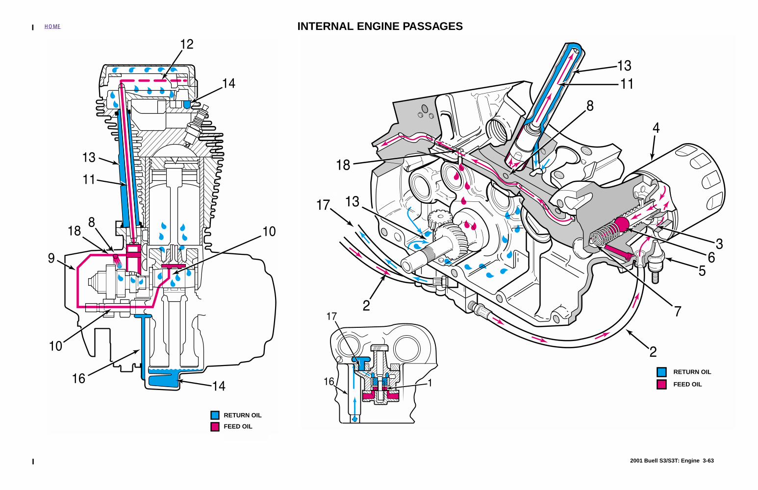
2001 Buell S3/S3T: Engine 3-63
HOME
RETURN OIL
FEED OIL
RETURN OIL
FEED OIL
INTERNAL ENGINE PASSAGES
S3/X1 FUEL SYSTEM 4
Table Of Contents
SUBJECT PAGE NO.
4.1 Specifications . . . . . . . . . . . . . . . . . . . . . . . . . . . . . . . . . . . . . . . . . . . . . . . . . . 4-14.2 Dynamic Digital Fuel Injection . . . . . . . . . . . . . . . . . . . . . . . . . . . . . . . . . . . . . 4-34.3 Diagnostic Introduction . . . . . . . . . . . . . . . . . . . . . . . . . . . . . . . . . . . . . . . . . . 4-54.4 Checking For Trouble Codes . . . . . . . . . . . . . . . . . . . . . . . . . . . . . . . . . . . . . . 4-64.5 Scanalyzer . . . . . . . . . . . . . . . . . . . . . . . . . . . . . . . . . . . . . . . . . . . . . . . . . . . . 4-84.6 Check Engine Lamp Diagnostics . . . . . . . . . . . . . . . . . . . . . . . . . . . . . . . . . . . 4-114.7 Breakout Box . . . . . . . . . . . . . . . . . . . . . . . . . . . . . . . . . . . . . . . . . . . . . . . . . . 4-134.8 Wiggle Test . . . . . . . . . . . . . . . . . . . . . . . . . . . . . . . . . . . . . . . . . . . . . . . . . . . 4-144.9 Initial Diagnostic Check . . . . . . . . . . . . . . . . . . . . . . . . . . . . . . . . . . . . . . . . . . 4-154.10 Check Engine Lamp Not Illuminated at Key ON . . . . . . . . . . . . . . . . . . . . . . 4-214.11 Check Engine Lamp On Continuously . . . . . . . . . . . . . . . . . . . . . . . . . . . . . . 4-244.12 Engine Cranks But Will Not Start . . . . . . . . . . . . . . . . . . . . . . . . . . . . . . . . . . 4-274.13 No ECM Power . . . . . . . . . . . . . . . . . . . . . . . . . . . . . . . . . . . . . . . . . . . . . . . 4-324.14 Fuel Pressure Test . . . . . . . . . . . . . . . . . . . . . . . . . . . . . . . . . . . . . . . . . . . . 4-354.15 Idle Speed Control . . . . . . . . . . . . . . . . . . . . . . . . . . . . . . . . . . . . . . . . . . . . . 4-414.16 Misfire . . . . . . . . . . . . . . . . . . . . . . . . . . . . . . . . . . . . . . . . . . . . . . . . . . . . . . 4-424.17 Trouble Code 11 . . . . . . . . . . . . . . . . . . . . . . . . . . . . . . . . . . . . . . . . . . . . . . 4-474.18 Trouble Code 13 . . . . . . . . . . . . . . . . . . . . . . . . . . . . . . . . . . . . . . . . . . . . . . 4-514.19 Trouble Code 14 . . . . . . . . . . . . . . . . . . . . . . . . . . . . . . . . . . . . . . . . . . . . . . 4-564.20 Trouble Code 15 . . . . . . . . . . . . . . . . . . . . . . . . . . . . . . . . . . . . . . . . . . . . . . 4-604.21 Trouble Code 16 . . . . . . . . . . . . . . . . . . . . . . . . . . . . . . . . . . . . . . . . . . . . . . 4-644.22 Trouble Codes 23 and 32 . . . . . . . . . . . . . . . . . . . . . . . . . . . . . . . . . . . . . . . 4-684.23 Trouble Codes 24 and 25 . . . . . . . . . . . . . . . . . . . . . . . . . . . . . . . . . . . . . . . 4-724.24 Trouble Code 33 . . . . . . . . . . . . . . . . . . . . . . . . . . . . . . . . . . . . . . . . . . . . . . 4-754.25 Trouble Code 35 . . . . . . . . . . . . . . . . . . . . . . . . . . . . . . . . . . . . . . . . . . . . . . 4-784.26 Trouble Code 44 . . . . . . . . . . . . . . . . . . . . . . . . . . . . . . . . . . . . . . . . . . . . . . 4-814.27 Trouble Codes 52, 53, 54 and 55 . . . . . . . . . . . . . . . . . . . . . . . . . . . . . . . . . 4-854.28 Trouble Code 56 . . . . . . . . . . . . . . . . . . . . . . . . . . . . . . . . . . . . . . . . . . . . . . 4-864.29 Electronic Control Module . . . . . . . . . . . . . . . . . . . . . . . . . . . . . . . . . . . . . . . 4-914.30 Cam Position Sensor and Rotor . . . . . . . . . . . . . . . . . . . . . . . . . . . . . . . . . . 4-934.31 Oxygen Sensor . . . . . . . . . . . . . . . . . . . . . . . . . . . . . . . . . . . . . . . . . . . . . . . 4-95
Continued on the next page

SUBJECT PAGE NO.
4.32 Engine Temperature Sensor . . . . . . . . . . . . . . . . . . . . . . . . . . . . . . . . . . . . . 4-964.33 Bank Angle Sensor . . . . . . . . . . . . . . . . . . . . . . . . . . . . . . . . . . . . . . . . . . . . 4-974.34 Intake Air Temperature Sensor . . . . . . . . . . . . . . . . . . . . . . . . . . . . . . . . . . . 4-984.35 Throttle Position Sensor . . . . . . . . . . . . . . . . . . . . . . . . . . . . . . . . . . . . . . . . 4-994.36 Fuel Tank . . . . . . . . . . . . . . . . . . . . . . . . . . . . . . . . . . . . . . . . . . . . . . . . . . . . 4-1004.37 Fuel Tank Vent Valve . . . . . . . . . . . . . . . . . . . . . . . . . . . . . . . . . . . . . . . . . . 4-1034.38 Inline Fuel Filter . . . . . . . . . . . . . . . . . . . . . . . . . . . . . . . . . . . . . . . . . . . . . . . 4-1054.39 Fuel Pump . . . . . . . . . . . . . . . . . . . . . . . . . . . . . . . . . . . . . . . . . . . . . . . . . . . 4-1064.40 Throttle Body and Intake Manifold . . . . . . . . . . . . . . . . . . . . . . . . . . . . . . . . . 4-1094.41 Air Cleaner . . . . . . . . . . . . . . . . . . . . . . . . . . . . . . . . . . . . . . . . . . . . . . . . . . . 4-1134.42 Evaporative Emissions Control . . . . . . . . . . . . . . . . . . . . . . . . . . . . . . . . . . . 4-115
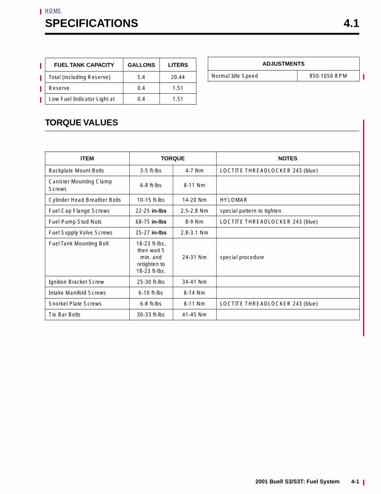
HOME
4
SPECIFICATIONS 4.1
FUEL TANK CAPACITY GALLONS LITERS
Total (including Reserve) 5.4 20.44
Reserve 0.4 1.51
Low Fuel Indicator Light at 0.4 1.51
ADJUSTMENTS
Normal Idle Speed 850-1050 RPM
TORQUE VALUES
ITEM TORQUE NOTES
Backplate Mount Bolts 3-5 ft-lbs 4-7 Nm LOCTITE THREADLOCKER 243 (blue)
Canister Mounting Clamp Screws
6-8 ft-lbs 8-11 Nm
Cylinder Head Breather Bolts 10-15 ft-lbs 14-20 Nm HYLOMAR
Fuel Cap Flange Screws 22-25 in-lbs 2.5-2.8 Nm special pattern to tighten
Fuel Pump Stud Nuts 68-75 in-lbs 8-9 Nm LOCTITE THREADLOCKER 243 (blue)
Fuel Supply Valve Screws 25-27 in-lbs 2.8-3.1 Nm
Fuel Tank Mounting Bolt 18-23 ft-lbs, then wait 5 min. and
retighten to 18-23 ft-lbs.
24-31 Nm special procedure
Ignition Bracket Screw 25-30 ft-lbs 34-41 Nm
Intake Manifold Screws 6-10 ft-lbs 8-14 Nm
Snorkel Plate Screws 6-8 ft-lbs 8-11 Nm LOCTITE THREADLOCKER 243 (blue)
Tie Bar Bolts 30-33 ft-lbs 41-45 Nm
2001 Buell S3/S3T: Fuel System 4-1

HOME
NOTES
4-2 2001 Buell S3/S3T: Fuel System