Embed Size (px)
Citation preview
8/7/2019 2000JUN02_CT_MSD_AN
http://slidepdf.com/reader/full/2000jun02ctmsdan 1/47
© 1994 Microchip Technology Inc. DS00587A-page 1
Interfacing to an LCD Module
AN587Interfacing to an LCD Module
3-49
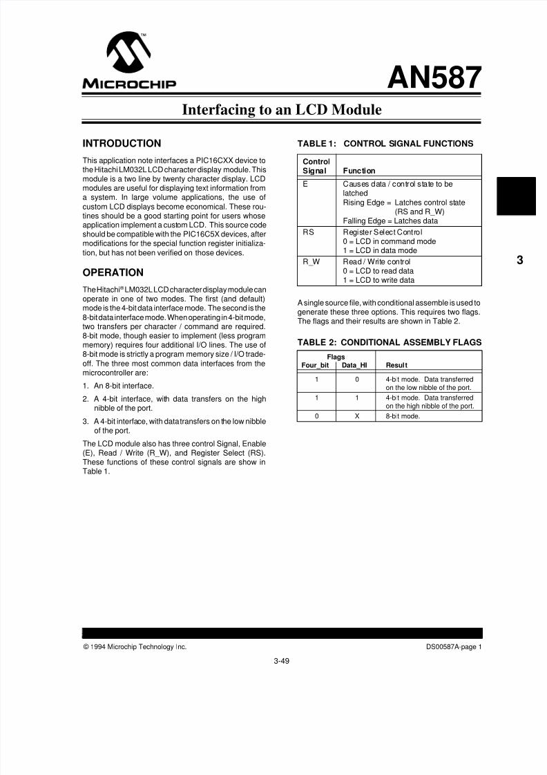
INTRODUCTION
This application note interfaces a PIC16CXX device tothe Hitachi LM032L LCD character display module. Thismodule is a two line by twenty character display. LCDmodules are useful for displaying text information froma system. In large volume applications, the use of
custom LCD displays become economical. These rou-tines should be a good starting point for users whoseapplication implement a custom LCD. This source codeshould be compatible with the PIC16C5X devices, aftermodifications for the special function register initializa-
tion, but has not been verified on those devices.
OPERATION
The Hitachi® LM032L LCD character display module canoperate in one of two modes. The first (and default)mode is the 4-bit data interface mode. The second is the
8-bit data interface mode. When operating in 4-bit mode,two transfers per character / command are required.8-bit mode, though easier to implement (less programmemory) requires four additional I/O lines. The use of8-bit mode is strictly a program memory size / I/O trade-
off. The three most common data interfaces from themicrocontroller are:
1. An 8-bit interface.
2. A 4-bit interface, with data transfers on the highnibble of the port.
3. A 4-bit interface, with data transfers on the low nibbleof the port.
The LCD module also has three control Signal, Enable(E), Read / Write (R_W), and Register Select (RS).These functions of these control signals are show inTable 1.
ControlSignal Function
E Causes data / control state to belatched
Rising Edge = Latches control state(RS and R_W)
Falling Edge = Latches data
RS Register Select Control0 = LCD in command mode1 = LCD in data mode
R_W Read / Write control0 = LCD to read data1 = LCD to write data
TABLE 1: CONTROL SIGNAL FUNCTIONS
A single source file, with conditional assemble is used togenerate these three options. This requires two flags.The flags and their results are shown in Table 2.
FlagsFour_bit Data_HI Result
1 0 4-bit mode. Data transferredon the low nibble of the port.
1 1 4-bit mode. Data transferredon the high nibble of the port.
0 X 8-bit mode.
TABLE 2: CONDITIONAL ASSEMBLY FLAGS

8/7/2019 2000JUN02_CT_MSD_AN
http://slidepdf.com/reader/full/2000jun02ctmsdan 2/47
DS00587A-page 2 © 1994 Microchip Technology Inc.
Interfacing to an LCD Module
3-50
assignment. This is accomplished with EQUate state-ments in the source code. See Appendices B - D.
Figure 1A through Figure 1C show the block diagramsfor the three different data interfaces. The LCD_CNTLand LCD_DATA lines are user definable to their port
FIGURE 1A: 8-BIT DATA INTERFACE
FIGURE 1B: 4-BIT MODE. DATA TRANSFERRED ON THE HIGH NIBBLE OF THE PORT
FIGURE 1C: 4-BIT MODE. DATA TRANSFERRED ON THE LOW NIBBLE OF THE PORT
PIC16CXX
LM032L
Port
Port<7:0>
LCD_CNTL
LCD_DATA
RS (4)R_W (5)E (6)
DB (14)-DB0 (7)
Vcc (2)Vo (3)Vss (1)
R1 (10KΩ)
R2 (330Ω)
PIC16CXX
LM032L
Port
Port
<7:4>
LCD_CNTL
LCD_DATA
RS (4)R_W (5)E (6)
DB7 (14)-DB4 (11)
DB3 (10)-DB0 (7)
Vcc (2)
Vo (3)Vss (1)
R1 (10KΩ)
R2 (330Ω)
PIC16CXX
LM032L
Port
Port
<3:0>
LCD_CNTL
LCD_DATA
RS (4)
R_W (5)
E (6)
DB7 (14)-DB4 (11)
DB3 (10)-DB0 (7)
Vcc (2)
Vo (3)
Vss (1)
R1 (10KΩ)
R2 (330Ω)

8/7/2019 2000JUN02_CT_MSD_AN
http://slidepdf.com/reader/full/2000jun02ctmsdan 3/47
© 1994 Microchip Technology Inc. DS00587A-page 3
Interfacing to an LCD Module
3-51
LCD ‘s (drivers) are slow devices when compared tomicrocontrollers. Care must be taken from having com-munication occur to quickly. The timing requirements ofthe LM032L are shown in Appendix A. It is recom-
mended that the complete specifications of the LM032Lbe acquired from Hitachi or an Hitachi distributor. Theliterature number is CE-E613Q and M24T013 for thedisplay driver.
When the module powers up, the default data transfer
mode is 8-bit. The initialization sequence only requirescommands that are 4-bit in length. The last initializationcommand then needs to be sent to the display to specifythe data transfer width (4- or 8-bit). Then a delay of
4.6 ms must be executed before the LCD module can beinitialized. Some of the LCD module commands are:
• 1 or 2 lines of characters
• Display on /off
• Clear display
• Increment / do not increment character address
pointer after each character• Load character address pointer
The initialization flow for the module is shown inFigure 2.
Initailization ends
Power ON
Wait more than 1.5ms after VDD rises to 4.5V
RS R/W DB7 DB6 DB5 DB4 DB3 DB2 DB1 DB0
0 0 0 0 1 1 x x x x
Wait more than 4.1 ms
RS R/W DB7 DB6 DB5 DB4 DB3 DB2 DB1 DB0
0 0 0 0 1 1 x x x x
Wait more than 100 µs
RS R/W DB7 DB6 DB5 DB4 DB3 DB2 DB1 DB0
0 0 0 0 1 1 x x x x
RS R/W DB7 DB6 DB5 DB4 DB3 DB2 DB1 DB0
0 0 0 0 1 1 N F x x
0 0 0 0 0 0 1 0 0 0
0 0 0 0 0 0 0 0 0 1
0 0 0 0 0 0 0 1 I/D S
Initailization ends
Power ON
Wait more than 1.5ms after VDD rises to 4.5V
RS R/W DB7 DB6 DB5 DB4
0 0 0 0 1 1
Wait more than 4.1 ms
Wait more than 100 µs
RS R/W DB7 DB6 DB5 DB4
0 0 0 0 1 0
0 0 0 0 1 0
0 0 0 0 0 0
0 0 0 0 0 0
0 0 N F x x
0 0 1 0 0 0
0 0 0 1 0 1
0 0 0 0 0 00 0 0 1 I/D S
RS R/W DB7 DB6 DB5 DB4
0 0 0 0 1 1
RS R/W DB7 DB6 DB5 DB4
0 0 0 0 1 1
BF cannot be checked before this instruction.
Function set (interface is 8 bits long)[ ]
BF cannot be checked before this instruction.
Function set (interface is 8 bits long)[ ]
BF cannot be checked before this instruction.
Function set (interface is 8 bits long)[ ]
Function set (set interface to be 4 bits long). Interface is 8 bits long.
Function Set
Display OFF
Display ON
Entry Mode Set
Interface is 8 / 4 bits long.Specify the number ofdisplay lines and characterfont.
[ ]The number of display lines and character font cannot
be changed afterwards.
1) When interface is 8 bits long: 2) When interface is 4 bits long:
FIGURE 2: INITIALIZATION FLOW FOR LCD MODULE

8/7/2019 2000JUN02_CT_MSD_AN
http://slidepdf.com/reader/full/2000jun02ctmsdan 4/47
DS00587A-page 4 © 1994 Microchip Technology Inc.
Interfacing to an LCD Module
After initialization, each character address is individuallyaddressable. Figure 3 shows the structure of the com-mand to specify the character address.
FIGURE 3: CHARACTER ADDRESSCOMMAND FORMAT
Written By: Mark Palmer - Sr. Application Engineer Code By: Mark Palmer / Scott Fink -
Sr. Application Engineers
3-52
The Hatachi Display Drive (HD44780A) has 80 bytes ofRAM. The LM032L modules only use 40 bytes of theavailable RAM (2 x 20 characters). It is possible to usethe remaining RAM locations for storage of other infor-mation.
Figure 4 shows the display data positions supported bythe display driver as well as the characters actuallydisplayed by the module (the shaded addresses).
The program example implemented here uses the autocharacter increment feature. This automatically incre-ments the character address pointer after each charac-ter is written to the display.
CONCLUSION
The Hitachi LM032L character display module is usefulfor the display of information. The selection of 4-bit or 8-bit data transfer mode is strictly a program memory size/ I/O resource trade-off. The supplied code is easily used
in one of three common data interfaces. The source iseasily modifiable to the designers specific applicationneeds. Other display modules / drivers maybe imple-mented with the appropriate modifications. Table 4shows the resource requirements for the three subrou-
tines SEND_CHAR, SEND_COMMAND, andBUSY_CHECK in the various data interface modes.
Program Data
Mode Memory Memory Verified On
8-bit 32 3 PICDEM-2 *
4-bit, Data transferred on the high nibble 53 3 PICDEM-2 *of the port
4-bit, Data transferred on the high nibble 53 3 Low Power Real Time
of the port Clock Board (AN582)
∗ Jumper J6 must be removed.
TABLE 4: RESOURCE REQUIREMENTS
FIGURE 4: DISPLAY DRIVER (DD) RAM LOCATIONS
Note: Shaded locations are displayed on the LM032L display module.
† Note: Not all addresses are usable.
DB7 DB0
DD ADDRLINE1
Address
Line number 0 = line 11 = line 2
Set DD RAM Address
†
00 01 02 03 04 05 06 07 08 09 0A 0B 0C 0D 0E 0F 10 11 12 13 14 20 21 22 23 24 25 26 27
40 41 42 43 44 45 46 47 48 49 4A 4B 4C 4D 4E 4F 50 51 52 53 54 60 61 62 63 64 65 66 67
1 2 3 4 5 6 7 8 9 10 11 12 13 14 15 16 17 18 19 20 21 33 34 35 36 37 38 39 40
1-line
2-line
digit Display position
DD RAM address(Hexadecimal)
.........
.........
.........

8/7/2019 2000JUN02_CT_MSD_AN
http://slidepdf.com/reader/full/2000jun02ctmsdan 5/47
© 1994 Microchip Technology Inc. DS00587A-page 5
Interfacing to an LCD Module
3-53
APPENDIX A: LM032L TIMING REQUIREMENTS
Parm # Symbol Characterisitics Min. Typ. Max. Unit
1 tcyc Enable cycle time 1.0 — — µs
2 PWEH Enable pulse width 450 — — ns
3 tEr, tEf Enable rise / fall time — — 25 ns
4 tAS RS, R/W set up time 140 — — ns
5 tDDR Data delay time — — 320 ns
6 tDSW Data set up time 195 — — ns
7 tH Hold time 20 — — ns
DATA WRITE INTERFACE TIMING
DATA READ INTERFACE TIMING
Note: Refer to Hitachi documentation for most current timing specifications.
TIMING CHARACTERISTICS
2.2V
0.6V
7
0.6V
7
3
0.6V
2.2V0.6V
Valid Data2.2V
0.6V
6
2.2V0.6V
3
1
2.2V0.6V
2
0.6V
4
2.2V
0.6VRS
R/W
E
DB0 DB7
2.2V0.6V
7
2.2V
7
0.6V
2.2V0.4V
Valid Data2.2V0.4V
5
2.2V0.6V
3
1
0.6V
2
2.2V
4
2.2V0.6VRS
R/W
E
DB0 DB7
32.2V

8/7/2019 2000JUN02_CT_MSD_AN
http://slidepdf.com/reader/full/2000jun02ctmsdan 6/47
DS00587A-page 6 © 1994 Microchip Technology Inc.
Interfacing to an LCD Module
3-54
LM032L PIN CONNECTION
Pin No. Symbol Level Function
1 Vss — 0V
2 VDD — +5V Power Supply
3 VO — —
4 RS H/L L: Instruction Code Input
H: Data Input
5 R/W H/L H: Data Read (LCD module→MPU)
L: Data Write (LCD module←MPU)
6 E H,H→L Enable Signal
7 DB0 H/L
8 DB1 H/L
9 DB2 H/L
10 DB3 H/L Data Bus Line
11 DB4 H/L Note (1), (2)
12 DB5 H/L13 DB6 H/L
14 DB7 H/L
Notes:
In the HD44780, the data can be sent in either a 4-bit 2-operation or a 8-bit 1-operation, so that it can interface to both4- and 8-bit MPUs.
(1) When interface data is 4-bits long, data is transferred using only 4 buses of DB DB7 and DB0 DB3 are not used.
Data transfer between the HD44780 and the MPU completes when 4-bit data is tranferred twice. Data of the higherorder 4 bits (contents of DB4 DB7 when interface data is 8-bits long) is tranferred first and then lower order 4 bits(contents of DB4 DB7 when interface data is 8-bits long).
(2) When interface data is 8-bits long, data is transferred using 8 data buses of DB0 DB7.~
~~
~~

8/7/2019 2000JUN02_CT_MSD_AN
http://slidepdf.com/reader/full/2000jun02ctmsdan 7/47
© 1994 Microchip Technology Inc. DS00587A-page 7
Interfacing to an LCD Module
APPENDIX B: 8-B
IT DATA INTERFACE LISTING
MPASM 00.00.68 Interm
ediate
LM032L.ASM
6-8-1994
0:53:47
PAGE
1
LOC
OBJECT CODE
LINE SOURCE TEXT
0001
LIST P=16C64, F=INH
X8M
0002 ;
0003 ; This program interfaces t
o a Hitachi (LM032L) 2 line by 2
0 character display
0004 ; module. The program assem
bles for either 4-bit or 8-bit d
ata interface, depending
0005 ; on the value of the 4bit
flag. LCD_DATA is the port which
supplies the data to
0006 ; the LM032L, while LCD_CNT
L is the port that has the contr
ol lines ( E, RS, R_W ).
0007 ; In 4-bit mode the data is
transfer on the high nibble of
the port ( PORT<7:4> ).
0008 ;
0009 ;
Program = LM032L.AS
M
0010 ;
Revision Date:
5-
10-94
0011 ;
0012 ;
0013
include <C74_reg.h>
0233
0013
0014
include <lm032l.h>
0014
0015 ;
0000
0016 Four_bit
EQU
FA
LSE
; Selects 4- or 8-bit
data transfers
0001
0017 Data_HI
EQU
TR
UE
; If 4-bit transfers, H
i or Low nibble of PORT
0018 ;
0019 ;
0020
if ( Four_bit && !Data_
HI )
0021 ;
0022 LCD_DATA
EQU
PO
RTB
0023 LCD_DATA_TRIS
EQU
TR
ISB
0024 ;
0025
else
0026 ;
0008
0027 LCD_DATA
EQU
PO
RTD
0088
0028 LCD_DATA_TRIS
EQU
TR
ISD
0029 ;
0030
endif
0031 ;
3-55

8/7/2019 2000JUN02_CT_MSD_AN
http://slidepdf.com/reader/full/2000jun02ctmsdan 8/47
DS00587A-page 8 © 1994 Microchip Technology Inc.
Interfacing to an LCD Module
0005
0032 LCD_CNTL
EQU
PORTA
0033 ;
0034 ;
0035 ;
0036 ; LCD Display Commands and Control Signal names.
0037 ;
0038
if ( Four_bit && !Data_HI )
0039 ;
0040 E
EQU
0
; LCD Enable control line
0041 R_W
EQU
1
; LCD Read/Write control line
0042 RS
EQU
2
; LCD Register Select control line
0043 ;
0044
else
0045 ;
0003
0046 E
EQU
3
; LCD Enable control line
0002
0047 R_W
EQU
2
; LCD Read/Write control line
0001
0048 RS
EQU
1
; LCD Register Select control line
0049 ;
0050
endif
0051 ;
0052 ;
0030
0053 TEMP1
EQU
0x030
0054 ;
0055
org
RESET_V
; RESET vector location
0000 2808
0056 RESET
GOTO
START
;
0057 ;
0058 ; This is the Periperal Interrupt routine. Should NOT get here
0059 ;
0061
org
ISR_V
; Interrupt vector location
0062 PER_INT_V
0004 1283
0063 ERROR1
BCF
STATUS, RP0
; Bank 0
0005 1407
0064
BSF
PORTC, 0
0006 1007
0065
BCF
PORTC, 0
0007 2804
0066
GOTO
ERROR1
0067 ;
0068 ;
0069 ;
0070 START
; POWER_ON Reset (Beginning of program)
0008 0183
0071
CLRF
STATUS
; Do initialization (Bank 0)
0009 018B
0072
CLRF
INTCON
000A 018C
0073
CLRF
PIR1
000B 1683
0074
BSF
STATUS, RP0
; Bank 1
000C 3000
0075
MOVLW
0x00
; The LCD module does n
ot like to work w/ weak pull-ups
000D 0081
0076
MOVWF
OPTION_R
;
3-56

8/7/2019 2000JUN02_CT_MSD_AN
http://slidepdf.com/reader/full/2000jun02ctmsdan 9/47

8/7/2019 2000JUN02_CT_MSD_AN
http://slidepdf.com/reader/full/2000jun02ctmsdan 10/47

8/7/2019 2000JUN02_CT_MSD_AN
http://slidepdf.com/reader/full/2000jun02ctmsdan 11/47

8/7/2019 2000JUN02_CT_MSD_AN
http://slidepdf.com/reader/full/2000jun02ctmsdan 12/47

8/7/2019 2000JUN02_CT_MSD_AN
http://slidepdf.com/reader/full/2000jun02ctmsdan 13/47

8/7/2019 2000JUN02_CT_MSD_AN
http://slidepdf.com/reader/full/2000jun02ctmsdan 14/47
8/7/2019 2000JUN02_CT_MSD_AN
http://slidepdf.com/reader/full/2000jun02ctmsdan 15/47

8/7/2019 2000JUN02_CT_MSD_AN
http://slidepdf.com/reader/full/2000jun02ctmsdan 16/47

8/7/2019 2000JUN02_CT_MSD_AN
http://slidepdf.com/reader/full/2000jun02ctmsdan 17/47

8/7/2019 2000JUN02_CT_MSD_AN
http://slidepdf.com/reader/full/2000jun02ctmsdan 18/47
DS00587A-page 18 © 1994 Microchip Technology Inc.
Interfacing to an LCD Module
008C 3468
050
1
retlw
‘h’
008D 3469
050
2
retlw
‘i’
008E 3470
050
3
retlw
‘p’
008F 3420
050
4
retlw
‘ ‘
0090 3454
050
5
retlw
‘T’
0091 3465
050
6
retlw
‘e’
0092 3463
050
7
retlw
‘c’
0093 3468
050
8
retlw
‘h’
0094 346E
050
9
retlw
‘n’
0095 346F
051
0
retlw
‘o’
0096 346C
051
1
retlw
‘l’
0097 346F
051
2
retlw
‘o’
0098 3467
051
3
retlw
‘g’
0099 3479
051
4
retlw
‘y’
051
5 Table_End
009A 3400
051
6
retlw
0
051
7 ;
051
8
if ( (Table & 0x0FF) >
= (Table_End & 0x0FF) )
051
9
MESSG
“Warning - User
Definded: Table Table crosses page boundry in computed jump”
052
0
endif
052
1 ;
052
2
052
3
052
4
052
5
end
052
6
052
7
052
8
052
9
053
0
3-66

8/7/2019 2000JUN02_CT_MSD_AN
http://slidepdf.com/reader/full/2000jun02ctmsdan 19/47
© 1994 Microchip Technology Inc. DS00587A-page 19
Interfacing to an LCD Module
MPASM 00.00.68 Interm
ediate
LM032L.ASM
6-8-1994
0:53:47
PAGE 14
MEMORY USAGE MAP (‘X’
= Used,
‘-’ = Unused)
0000 : X—XXXXXXXXXXXX
XXXXXXXXXXXXXXXX XXXXXXXXXXXXXX
XX XXXXXXXXXXXXXXXX
0040 : XXXXXXXXXXXXXX
XX XXXXXXXXXXXXXXXX XXXXXXXXXXXX
XXXX XXXXXXXXXXXXXXXX
0080 : XXXXXXXXXXXXXX
XX XXXXXXXXXXX—— ———————— ——————
——
00C0 : ———————— —————
——— ———————— ————————
All other memory bloc
ks unused.
Errors
:
0
Warnings :
13
NOTE:
Special Functi
on Register data memory location
s in Bank 1, are
specified by t
heir true address in the file C7
4_REG.H.
The use of the
MPASM assembler will generate a
warning message,
when these lab
les are used with direct address
ing.
3-67

8/7/2019 2000JUN02_CT_MSD_AN
http://slidepdf.com/reader/full/2000jun02ctmsdan 20/47
DS00587A-page 20 © 1994 Microchip Technology Inc.
Interfacing to an LCD Module
APPENDIX C: 4-BIT DATA INTERFACE, HIGH N
IBBLE LISTING
MPASM 00.00.68 Intermediate
LM032L.ASM
6-8-1994
0:59:12
PAGE
1
LOC
OBJECT CODE
LINE SOURCE TEXT
0001
LIST P=16C64, F=INHX8M
0002 ;
0003 ; This program interfaces to a Hitachi (LM032L) 2 line by 20 character display
0004 ; module. The program assembles for either 4-bit or 8-bit data interface, depending
0005 ; on the value of the 4bit flag. LCD_DATA is the port which supplies the data to
0006 ; the LM032L, while LCD_CNTL is the port that has the control lines ( E, RS, R_W ).
0007 ; In 4-bit mode the data is transfer on the high nibble of the port ( PORT<7:4> ).
0008 ;
0009 ;
Program = LM032L.ASM
0010 ;
Revision Date:
5-10-94
0011 ;
0012 ;
0013
include <C74_reg.h>
0233
0013
0014
include <lm032l.h>
0014
0015 ;
0001
0016 Four_bit
EQU
TRUE
; Selects 4- or 8-bit data transfers
0001
0017 Data_HI
EQU
TRUE
; If 4-bit transfers, Hi or Low nibble of PORT
0018 ;
0019 ;
0020
if ( Four_bit && !Data_HI )
0021 ;
0022 LCD_DATA
EQU
PORTB
0023 LCD_DATA_TRIS
EQU
TRISB
0024 ;
0025
else
0026 ;
0008
0027 LCD_DATA
EQU
PORTD
0088
0028 LCD_DATA_TRIS
EQU
TRISD
0029 ;
0030
endif
0031 ;
0005
0032 LCD_CNTL
EQU
PORTA
0033 ;
0034 ;
3-68

8/7/2019 2000JUN02_CT_MSD_AN
http://slidepdf.com/reader/full/2000jun02ctmsdan 21/47

8/7/2019 2000JUN02_CT_MSD_AN
http://slidepdf.com/reader/full/2000jun02ctmsdan 22/47

8/7/2019 2000JUN02_CT_MSD_AN
http://slidepdf.com/reader/full/2000jun02ctmsdan 23/47

8/7/2019 2000JUN02_CT_MSD_AN
http://slidepdf.com/reader/full/2000jun02ctmsdan 24/47

8/7/2019 2000JUN02_CT_MSD_AN
http://slidepdf.com/reader/full/2000jun02ctmsdan 25/47

8/7/2019 2000JUN02_CT_MSD_AN
http://slidepdf.com/reader/full/2000jun02ctmsdan 26/47

8/7/2019 2000JUN02_CT_MSD_AN
http://slidepdf.com/reader/full/2000jun02ctmsdan 27/47

8/7/2019 2000JUN02_CT_MSD_AN
http://slidepdf.com/reader/full/2000jun02ctmsdan 28/47

8/7/2019 2000JUN02_CT_MSD_AN
http://slidepdf.com/reader/full/2000jun02ctmsdan 29/47

8/7/2019 2000JUN02_CT_MSD_AN
http://slidepdf.com/reader/full/2000jun02ctmsdan 30/47

8/7/2019 2000JUN02_CT_MSD_AN
http://slidepdf.com/reader/full/2000jun02ctmsdan 31/47
© 1994 Microchip Technology Inc. DS00587A-page 31
Interfacing to an LCD Module
0520
endif
0521 ;
0522
0523
0524
0525
end
0526
0527
0528
0529
0530
MPASM 00.00.68 Interm
ediate
LM032L.ASM
6-8-1994
0:59:12
PAGE 14
MEMORY USAGE MAP (‘X’
= Used,
‘-’ = Unused)
0000 : X—XXXXXXXXXXXX
XXXXXXXXXXXXXXXX XXXXXXXXXXXXXX
XX XXXXXXXXXXXXXXXX
0040 : XXXXXXXXXXXXXX
XX XXXXXXXXXXXXXXXX XXXXXXXXXXXX
XXXX XXXXXXXXXXXXXXXX
0080 : XXXXXXXXXXXXXX
XX XXXXXXXXXXXXXXXX XXXXXXXXXXXX
XXXX X———————
00C0 : ———————— —————
——— ———————— ————————
All other memory bloc
ks unused.
Errors
:
0
Warnings :
13
NOTE:
Special Function Register data memory locations in Bank 1, are
specified by their true address in the file C74_REG.H.
The use of the MPASM assembler will generate a warning message,
when these lables are used with direct addressing.
3-79

8/7/2019 2000JUN02_CT_MSD_AN
http://slidepdf.com/reader/full/2000jun02ctmsdan 32/47
DS00587A-page 32 © 1994 Microchip Technology Inc.
Interfacing to an LCD Module
APPENDIX D: 4-BIT DATA INTERFACE, LOW NIBBLE LISTING
MPASM 00.00.68 Intermediate
LM032L.ASM
6-8-1994
5:29:26
PAGE
1
LOC
OBJECT CODE
LINE SOURCE TEXT
0001
LIST P=16C64, F=INHX8M
0002 ;
0003 ; This program interfaces to a Hitachi (LM032L) 2 line by 20 character display
0004 ; module. The program assembles for either 4-bit or 8-bit data interface, depending
0005 ; on the value of the 4bit flag. LCD_DATA is the port which supplies the data to
0006 ; the LM032L, while LCD_CNTL is the port that has the control lines ( E, RS, R_W ).
0007 ; In 4-bit mode the data is transfer on the high nibble of the port ( PORT<7:4> ).
0008 ;
0009 ;
Program = LM032L.ASM
0010 ;
Revision Date:
5-10-94
0011 ;
0012 ;
0013
include <C74_reg.h>
0233
0013
0014
include <lm032l.h>
0014
0015 ;
0001
0016 Four_bit
EQU
TRUE
; Selects 4- or 8-bit data transfers
0000
0017 Data_HI
EQU
FALSE
; If 4-bit transfers, Hi or Low nibble of PORT
0018 ;
0019 ;
0020
if ( Four_bit && !Data_HI )
0021 ;
0006
0022 LCD_DATA
EQU
PORTB
0086
0023 LCD_DATA_TRIS
EQU
TRISB
0024 ;
0025
else
0026 ;
0027 LCD_DATA
EQU
PORTD
0028 LCD_DATA_TRIS
EQU
TRISD
0029 ;
0030
endif
0031 ;
0005
0032 LCD_CNTL
EQU
PORTA
0033 ;
0034 ;
0035 ;
3-80

8/7/2019 2000JUN02_CT_MSD_AN
http://slidepdf.com/reader/full/2000jun02ctmsdan 33/47

8/7/2019 2000JUN02_CT_MSD_AN
http://slidepdf.com/reader/full/2000jun02ctmsdan 34/47

8/7/2019 2000JUN02_CT_MSD_AN
http://slidepdf.com/reader/full/2000jun02ctmsdan 35/47

8/7/2019 2000JUN02_CT_MSD_AN
http://slidepdf.com/reader/full/2000jun02ctmsdan 36/47

8/7/2019 2000JUN02_CT_MSD_AN
http://slidepdf.com/reader/full/2000jun02ctmsdan 37/47

8/7/2019 2000JUN02_CT_MSD_AN
http://slidepdf.com/reader/full/2000jun02ctmsdan 38/47

8/7/2019 2000JUN02_CT_MSD_AN
http://slidepdf.com/reader/full/2000jun02ctmsdan 39/47

8/7/2019 2000JUN02_CT_MSD_AN
http://slidepdf.com/reader/full/2000jun02ctmsdan 40/47

8/7/2019 2000JUN02_CT_MSD_AN
http://slidepdf.com/reader/full/2000jun02ctmsdan 41/47

8/7/2019 2000JUN02_CT_MSD_AN
http://slidepdf.com/reader/full/2000jun02ctmsdan 42/47

8/7/2019 2000JUN02_CT_MSD_AN
http://slidepdf.com/reader/full/2000jun02ctmsdan 43/47
© 1994 Microchip Technology Inc. DS00587A-page 43
Interfacing to an LCD Module
0520
endif
0521 ;
0522
0523
0524
0525
end
0526
0527
0528
0529
0530
MPASM 00.00.68 Interm
ediate
LM032L.ASM
6-8-1994
5:29:26
PAGE 14
MEMORY USAGE MAP (‘X’
= Used,
‘-’ = Unused)
0000 : X—XXXXXXXXXXXX
XXXXXXXXXXXXXXXX XXXXXXXXXXXXXX
XX XXXXXXXXXXXXXXXX
0040 : XXXXXXXXXXXXXX
XX XXXXXXXXXXXXXXXX XXXXXXXXXXXX
XXXX XXXXXXXXXXXXXXXX
0080 : XXXXXXXXXXXXXX
XX XXXXXXXXXXXXXXXX XXXXXXXXXXXX
XXXX X———————
00C0 : ———————— —————
——— ———————— ————————
All other memory bloc
ks unused.
Errors
:
0
Warnings :
13
NOTE:
Special Functi
on Register data memory location
s in Bank 1, are
specified by t
heir true address in the file C7
4_REG.H.
The use of the
MPASM assembler will generate a
warning message,
when these lab
les are used with direct address
ing.
3-91
8/7/2019 2000JUN02_CT_MSD_AN
http://slidepdf.com/reader/full/2000jun02ctmsdan 44/47
DS00587A-page 44 © 1994 Microchip Technology Inc.
Interfacing to an LCD Module
nolist
;******************
********************************
****************************
; ;
This is the cust
om Header File for the real time
clock application note
;
PROGRAM:
CLOCK.H
;
Revision:
5-10-94
; ;******************
********************************
****************************
; This is used for
the ASSEMBLER to recalculate certain frequency
; dependant variabl
es. The value of Dev_Freq must be changed to
; reflect the frequ
ency that the device actually operates at.
; Dev_Freq
EQU
D’4000000'
; Device Frequency is 4 MHz
DB_HI_BYTE
EQU
(HIGH ((( Dev
_Freq / 4 ) * 1 / D’1000' ) / 3
) ) + 1
LCD_INIT_DELAY
EQU
(HIGH ((( Dev
_Freq / 4 ) * D’46' / D’10000' )
/ 3 ) ) + 1
INNER_CNTR
EQU
40
; RAM Location
OUTER_CNTR
EQU
41
; RAM Location
T1OSO
EQU
0
; The RC0 / T1OSO / T1CKI
; RESET_V
EQU
0x0000
; Address of RESET Vector
ISR_V
EQU
0x0004
; Address of Interrupt Vector
PMEM_END
EQU
0x07FF
; Last address in Program Memo
ry
TABLE_ADDR
EQU
0x0400
; Address where to start Table
s
; HR_MIN_SW
EQU
0x7
; The switch to select the uni
ts
INC_SW
EQU
0x6
; The switch to increment the
selected units
CLR_MIN_SW
EQU
0x5
; The switch to clear the minu
tes and seconds
; FLAG_REG
EQU
0x020
; Register which contains flag
bits
; ; ;
|
AM
|
—
|
—
| KEY_INPUT |
—
|
—
| MIN_UNIT | HR_UNIT |
; ; AM
EQU
0x07
; Flag to specify if AM or PM
; KEY_INPUT
EQU
0x04
; Flag to specify if doing key
inputs
; MIN_UNIT
EQU
0x01
; Flags to specify which units
to operate on
HR_UNIT
EQU
0x00
;
(HRS, MIN, or none)
; HRS
EQU
0x030
; Holds counter value for HOUR
S
MIN
EQU
0x031
; Holds counter value for MINU
TES
SECS
EQU
0x032
; Holds counter value for SECO
NDS
3-92
APPENDIX E: LM0
32L.H

8/7/2019 2000JUN02_CT_MSD_AN
http://slidepdf.com/reader/full/2000jun02ctmsdan 45/47
© 1994 Microchip Technology Inc. DS00587A-page 45
Interfacing to an LCD Module
MSD
EQU
0x033
; Temporary register, Holds Mo
st Significant Digit of BIN to B
CD conversion
LSD
EQU
0x034
; Temporary register, Holds Le
ast Significant Digit of BIN to
BCD conversion
TEMP
EQU
0x035
; Temporary register
CHAR
EQU
0x036
; Temporary register, Holds va
lue to send to LCD module.
; WAIT_CNTR
EQU
0x040
; Counter that holds wait time
for key inputs
; ; ; LCD Module comman
ds
; DISP_ON
EQU
0x00C
; Display on
DISP_ON_C
EQU
0x00E
; Display on, Cursor on
DISP_ON_B
EQU
0x00F
; Display on, Cursor on, Blink
cursor
DISP_OFF
EQU
0x008
; Display off
CLR_DISP
EQU
0x001
; Clear the Display
ENTRY_INC
EQU
0x006
;
ENTRY_INC_S
EQU
0x007
;
ENTRY_DEC
EQU
0x004
;
ENTRY_DEC_S
EQU
0x005
;
DD_RAM_ADDR
EQU
0x080
; Least Significant 7-bit are
for address
DD_RAM_UL
EQU
0x080
; Upper Left coner of the Disp
lay
;
list
3-93

8/7/2019 2000JUN02_CT_MSD_AN
http://slidepdf.com/reader/full/2000jun02ctmsdan 46/47
DS00587A-page 46 © 1994 Microchip Technology Inc.
Interfacing to an LCD Module
3-94
NOTES:
8/7/2019 2000JUN02_CT_MSD_AN
http://slidepdf.com/reader/full/2000jun02ctmsdan 47/47
WORLDWIDE SALES & SERVICE
AMERICAS (continued)
San Jose
Microchip Technology Inc.
2107 North First Street, Suite 590San Jose, CA 95131Tel: 408 436-7950 Fax: 408 436-7955
ASIA/PACIFIC
Hong KongMicrochip TechnologyUnit No. 3002-3004, Tower 1Metroplaza223 Hing Fong RoadKwai Fong, N.T. Hong KongTel: 852 2 401 1200 Fax: 852 2 401 3431
Korea
Microchip Technology168-1, Youngbo Bldg. 3 FloorSamsung-Dong, Kangnam-Ku,Seoul, Korea
Tel: 82 2 554 7200 Fax: 82 2 558 5934Singapore
Microchip Technology200 Middle Road#10-03 Prime CentreSingapore 188980Tel: 65 334 8870 Fax: 65 334 8850
Taiwan
Microchip Technology10F-1C 207Tung Hua North RoadTaipei, Taiwan, ROCTel: 886 2 717 7175 Fax: 886 2 545 0139
EUROPE
United Kingdom
Arizona Microchip Technology Ltd.
Unit 6, The CourtyardMeadow Bank, Furlong RoadBourne End, Buckinghamshire SL8 5AJTel: 44 0 1628 851077 Fax: 44 0 1628 850259
France
Arizona Microchip Technology SARL2 Rue du Buisson aux Fraises91300 Massy - FranceTel: 33 1 69 53 63 20 Fax: 33 1 69 30 90 79
Germany
Arizona Microchip Technology GmbHGustav-Heinemann-Ring 125D-81739 Muenchen, GermanyTel: 49 89 627 144 0 Fax: 49 89 627 144 44
Italy
Arizona Microchip Technology SRLCentro Direzionale ColleoniPalazzo Pegaso Ingresso No. 2Via Paracelso 23, 20041Agrate Brianza (MI) ItalyTel: 39 039 689 9939 Fax: 39 039 689 9883
JAPANMicrochip Technology Intl. Inc.Benex S-1 6F3-18-20, Shin YokohamaKohoku-Ku, YokohamaKanagawa 222 JapanTel: 81 45 471 6166 Fax: 81 45 471 6122
9/22/95
AMERICAS
Corporate Office
Microchip Technology Inc.
2355 West Chandler Blvd.Chandler, AZ 85224-6199Tel: 602 786-7200 Fax: 602 786-7277Technical Support: 602 786-7627
Web: http://www.mchip.com/microhip
Atlanta
Microchip Technology Inc.500 Sugar Mill Road, Suite 200BAtlanta, GA 30350Tel: 770 640-0034 Fax: 770 640-0307
Boston
Microchip Technology Inc.5 Mount Royal AvenueMarlborough, MA 01752Tel: 508 480-9990 Fax: 508 480-8575
Chicago
Microchip Technology Inc.333 Pierce Road, Suite 180Itasca, IL 60143Tel: 708 285-0071 Fax: 708 285-0075
DallasMicrochip Technology Inc.14651 Dallas Parkway, Suite 816Dallas, TX 75240-8809Tel: 214 991-7177 Fax: 214 991-8588
DaytonMicrochip Technology Inc.35 Rockridge RoadEnglewood, OH 45322Tel: 513 832-2543 Fax: 513 832-2841
Los AngelesMicrochip Technology Inc.18201 Von Karman, Suite 455
Irvine, CA 92715Tel: 714 263-1888 Fax: 714 263-1338
New York
Microchip Technology Inc.150 Motor Parkway, Suite 416Hauppauge, NY 11788Tel: 516 273-5305 Fax: 516 273-5335


