Embed Size (px)
Citation preview
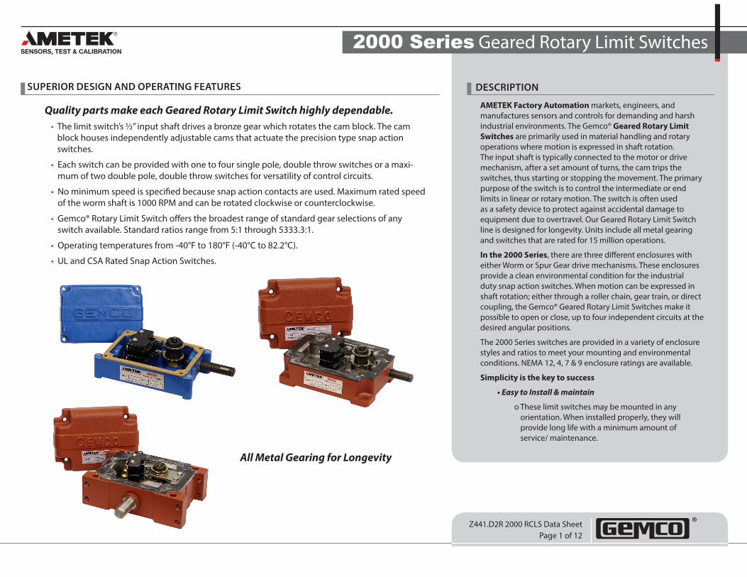
2000 Series Geared Rotary Limit Switches
Z441.D2R 2000 RCLS Data SheetPage 1 of 12
SUPERIOR DESIGN AND OPERATING FEATURES DESCRIPTION
Quality parts make each Geared Rotary Limit Switch highly dependable.• The limit switch’s ½” input shaft drives a bronze gear which rotates the cam block. The cam
block houses independently adjustable cams that actuate the precision type snap action switches.
• Each switch can be provided with one to four single pole, double throw switches or a maxi-mum of two double pole, double throw switches for versatility of control circuits.
• No minimum speed is specified because snap action contacts are used. Maximum rated speed of the worm shaft is 1000 RPM and can be rotated clockwise or counterclockwise.
• Gemco® Rotary Limit Switch offers the broadest range of standard gear selections of any switch available. Standard ratios range from 5:1 through 5333.3:1.
• Operating temperatures from -40°F to 180°F (-40°C to 82.2°C).
• UL and CSA Rated Snap Action Switches.
All Metal Gearing for Longevity
AMETEK Factory Automation markets, engineers, and manufactures sensors and controls for demanding and harsh industrial environments. The Gemco® Geared Rotary Limit Switches are primarily used in material handling and rotary operations where motion is expressed in shaft rotation. The input shaft is typically connected to the motor or drive mechanism, after a set amount of turns, the cam trips the switches, thus starting or stopping the movement. The primary purpose of the switch is to control the intermediate or end limits in linear or rotary motion. The switch is often used as a safety device to protect against accidental damage to equipment due to overtravel. Our Geared Rotary Limit Switch line is designed for longevity. Units include all metal gearing and switches that are rated for 15 million operations.
In the 2000 Series, there are three different enclosures with either Worm or Spur Gear drive mechanisms. These enclosures provide a clean environmental condition for the industrial duty snap action switches. When motion can be expressed in shaft rotation; either through a roller chain, gear train, or direct coupling, the Gemco® Geared Rotary Limit Switches make it possible to open or close, up to four independent circuits at the desired angular positions.
The 2000 Series switches are provided in a variety of enclosure styles and ratios to meet your mounting and environmental conditions. NEMA 12, 4, 7 & 9 enclosure ratings are available.
Simplicity is the key to success
• Easy to Install & maintain
o These limit switches may be mounted in any orientation. When installed properly, they will provide long life with a minimum amount of service/ maintenance.
2000 Series Geared Rotary Limit Switches
Z441.D2R 2000 RCLS Data SheetPage 2 of 12
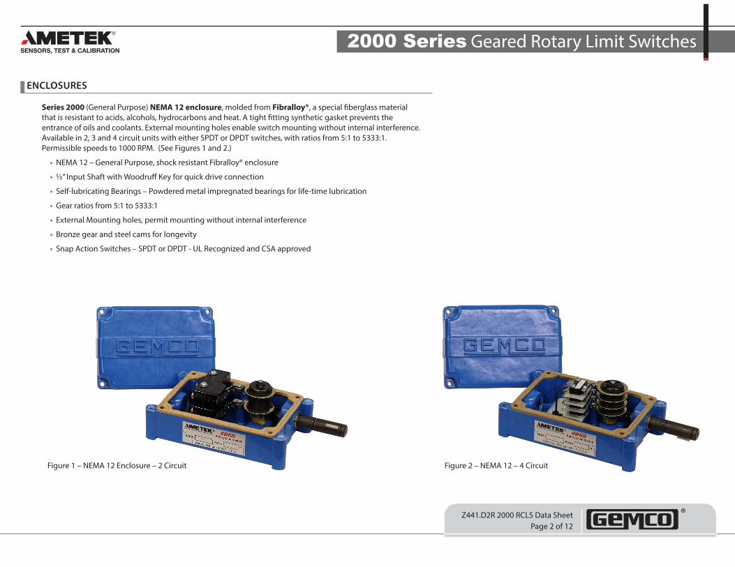
Series 2000 (General Purpose) NEMA 12 enclosure, molded from Fibralloy®, a special fiberglass material that is resistant to acids, alcohols, hydrocarbons and heat. A tight fitting synthetic gasket prevents the entrance of oils and coolants. External mounting holes enable switch mounting without internal interference. Available in 2, 3 and 4 circuit units with either SPDT or DPDT switches, with ratios from 5:1 to 5333:1. Permissible speeds to 1000 RPM. (See Figures 1 and 2.)
• NEMA 12 – General Purpose, shock resistant Fibralloy® enclosure
• ½” Input Shaft with Woodruff Key for quick drive connection
• Self-lubricating Bearings – Powdered metal impregnated bearings for life-time lubrication
• Gear ratios from 5:1 to 5333:1
• External Mounting holes, permit mounting without internal interference
• Bronze gear and steel cams for longevity
• Snap Action Switches – SPDT or DPDT - UL Recognized and CSA approved
ENCLOSURES
Figure 1 – NEMA 12 Enclosure – 2 Circuit Figure 2 – NEMA 12 – 4 Circuit
2000 Series Geared Rotary Limit Switches
Z441.D2R 2000 RCLS Data SheetPage 3 of 12
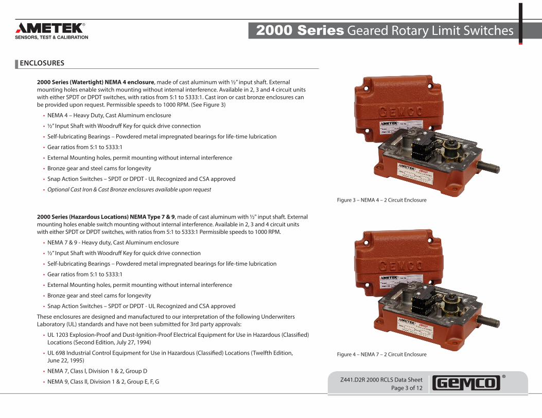
2000 Series (Watertight) NEMA 4 enclosure, made of cast aluminum with ½” input shaft. External mounting holes enable switch mounting without internal interference. Available in 2, 3 and 4 circuit units with either SPDT or DPDT switches, with ratios from 5:1 to 5333:1. Cast iron or cast bronze enclosures can be provided upon request. Permissible speeds to 1000 RPM. (See Figure 3)
• NEMA 4 – Heavy Duty, Cast Aluminum enclosure
• ½” Input Shaft with Woodruff Key for quick drive connection
• Self-lubricating Bearings – Powdered metal impregnated bearings for life-time lubrication
• Gear ratios from 5:1 to 5333:1
• External Mounting holes, permit mounting without internal interference
• Bronze gear and steel cams for longevity
• Snap Action Switches – SPDT or DPDT - UL Recognized and CSA approved
• Optional Cast Iron & Cast Bronze enclosures available upon request
2000 Series (Hazardous Locations) NEMA Type 7 & 9, made of cast aluminum with ½" input shaft. External mounting holes enable switch mounting without internal interference. Available in 2, 3 and 4 circuit units with either SPDT or DPDT switches, with ratios from 5:1 to 5333:1 Permissible speeds to 1000 RPM.
• NEMA 7 & 9 - Heavy duty, Cast Aluminum enclosure
• ½” Input Shaft with Woodruff Key for quick drive connection
• Self-lubricating Bearings – Powdered metal impregnated bearings for life-time lubrication
• Gear ratios from 5:1 to 5333:1
• External Mounting holes, permit mounting without internal interference
• Bronze gear and steel cams for longevity
• Snap Action Switches – SPDT or DPDT - UL Recognized and CSA approved
These enclosures are designed and manufactured to our interpretation of the following Underwriters Laboratory (UL) standards and have not been submitted for 3rd party approvals:
• UL 1203 Explosion-Proof and Dust-Ignition-Proof Electrical Equipment for Use in Hazardous (Classified) Locations (Second Edition, July 27, 1994)
• UL 698 Industrial Control Equipment for Use in Hazardous (Classified) Locations (Twelfth Edition, June 22, 1995)
• NEMA 7, Class l, Division 1 & 2, Group D
• NEMA 9, Class ll, Division 1 & 2, Group E, F, G
ENCLOSURES
Figure 3 – NEMA 4 – 2 Circuit Enclosure
Figure 4 – NEMA 7 – 2 Circuit Enclosure
2000 Series Geared Rotary Limit Switches
Z441.D2R 2000 RCLS Data SheetPage 4 of 12
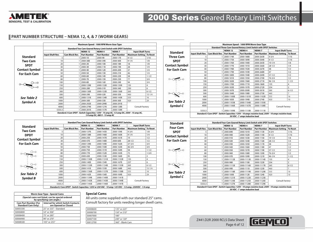
PART NUMBER STRUCTURE – NEMA 12, 4, & 7 (WORM GEARS)
Maximum Speed - 1000 RPM Worm Gear Type
Standard Two Cam
SPDT Contact Symbol
For Each Cam
See Table 2 Symbol A
Standard Two Cam Geared Rotary Limit Switch with SPDT SwitchesNEMA 12 NEMA 4 NEMA 7 Input Shaft Turns
Input Shaft Rev. Cam Block Rev. Part Number Part Number Part Number Maximum Setting To Reset5 1 2000-1B 2000-9B 2000-17B 4-1/2 1/16
10 1 2000-38B 2000-39B 2000-40B 9-1/4 1/820 1 2000-2B 2000-10B 2000-18B 18 1/830 1 2000-3B 2000-11B 2000-19B 28 1/440 1 2000-4B 2000-12B 2000-20B 37 1/450 1 2000-5B 2000-13B 2000-21B 46 1/460 1 2000-6B 2000-14B 2000-22B 58 1-1/280 1 2000-7B 2000-15B 2000-23B 77 3/4
100 1 2000-8B 2000-16B 2000-24B 94 3/4150 1 2000-129B 2000-132B 2000-135B 135 4250 1 2000-28B 2000-31B 2000-34B 230 6300 1 2000-130B 2000-133B 2000-136B 265 6-1/2500 1 2000-29B 2000-32B 2000-35B 460 15-1/4600 1 2000-131B 2000-134B 2000-143B 555 16
1000 1 2000-30B 2000-33B 2000-36B 920 292000 1 2000-292B 2000-299B 2000-291B
Consult Factory4000 1 2000-279B 2000-127B 2000-128B5333.3 1 2000-281B 2000-157B 2000-158BStandard 2 Cam SPDT - Switch Capacities: 125V - 15 amp AC, 1/2 amp DC, 250V - 15 amp AC,
1/4 amp DC, 480 V - 15 amp AC
Standard Two Cam
DPDT Contact Symbol
For Each Cam
See Table 2 Symbol B
Standard Two Cam Geared Rotary Limit Switch with DPDT SwitchesNEMA 12 NEMA 4 NEMA 7 Input Shaft Turns
Input Shaft Rev. Cam Block Rev. Part Number Part Number Part Number Maximum Setting To Reset5 1 2000-137B 2000-145B 2000-159B 4-3/4 1/8
10 1 2000-138B 2000-146B 2000-160B 9-1/4 1/420 1 2000-25B 2000-147B 2000-161B 19 1/230 1 2000-47B 2000-148B 2000-60B 28-1/2 1/240 1 2000-139B 2000-149B 2000-162B 37-3/4 3/450 1 2000-73B 2000-150B 2000-163B 46-3/4 3/460 1 2000-75B 2000-151B 2000-164B 58 1-1/280 1 2000-77B 2000-152B 2000-165B 75 1-3/4
100 1 2000-43B 2000-153B 2000-166B 95 2150 1 2000-1130B 2000-1131B 2000-1132B 135 4250 1 2000-140B 2000-154B 2000-167B 237 6300 1 2000-1133B 2000-1134B 2000-1135B 265 6-1/2500 1 2000-141B 2000-155B 2000-168B 460 15-1/4600 1 2000-1136B 2000-1137B 2000-1138B 555 16
1000 1 2000-142B 2000-156B 2000-169B 920 292000 1 2000-1139B 2000-1140B 2000-1141B
Consult Factory4000 1 2000-1142B 2000-1143B 2000-1144B5333.3 1 2000-1145B 2000-1146B 2000-1147B
Standard 2 Cam DPDT - Switch Capacities: 125V or 250 VAC - 10 amp: 125 VDC - 1/2 amp,: 250VDC - 1/4 amp
Maximum Speed - 1000 RPM Worm Gear Type
Standard Three Cam
SPDT Contact Symbol
For Each Cam
See Table 2 Symbol C
Standard Three Cam Geared Rotary Limit Switch with SPDT SwitchesNEMA 12 NEMA 4 NEMA 7 Input Shaft Turns
Input Shaft Rev. Cam Block Rev. Part Number Part Number Part Number Maximum Setting To Reset5 1 2000-174B 2000-188B 2000-263B 4-3/4 1/16
10 1 2000-175B 2000-189B 2000-264B 9-1/2 1/1620 1 2000-176B 2000-190B 2000-265B 19-1/4 1/830 1 2000-177B 2000-191B 2000-266B 28-1/2 1/440 1 2000-178B 2000-192B 2000-267B 38 1/250 1 2000-179B 2000-193B 2000-268B 47 1/260 1 2000-180B 2000-194B 2000-269B 57-1/2 1/280 1 2000-181B 2000-195B 2000-270B 76-3/4 1/2
100 1 2000-182B 2000-196B 2000-271B 96-1/4 1-1/2150 1 2000-170B 2000-171B 2000-186B 135 4250 1 2000-183B 2000-197B 2000-272B 234 2300 1 2000-187B 2000-300B 2000-301B 265 6-1/2500 1 2000-184B 2000-198B 2000-273B 460 7600 1 2000-1100B 2000-1101B 2000-1102B 555 16
1000 1 2000-185B 2000-199B 2000-274B 920 102000 1 2000-1103B 2000-1104B 2000-1105B
Consult Factory4000 1 2000-1106B 2000-1107B 2000-1108B
5333.3 1 2000-1109B 2000-1110B 2000-1111BStandard 3 Cam SPDT - Switch Capacities: 125V - 10 amps resistive load, 250V - 10 amps resistive load,
30 VDC - 7 amps industive load
Standard Four Cam
SPDT Contact Symbol
For Each Cam
See Table 2 Symbol C
Standard Four Cam Geared Rotary Limit Switch with SPDT SwitchesNEMA 12 NEMA 4 NEMA 7 Input Shaft Turns
Input Shaft Rev. Cam Block Rev. Part Number Part Number Part Number Maximum Setting To Reset5 1 2000-89B 2000-101B 2000-113B 4-3/4 1/16
10 1 2000-90B 2000-102B 2000-114B 9-1/2 1/1620 1 2000-91B 2000-103B 2000-115B 19-1/4 1/830 1 2000-92B 2000-104B 2000-116B 28-1/2 1/440 1 2000-93B 2000-105B 2000-117B 38 1/250 1 2000-94B 2000-106B 2000-118B 47 1/260 1 2000-95B 2000-107B 2000-119B 57-1/2 1/280 1 2000-96B 2000-108B 2000-120B 76-3/4 1/2
100 1 2000-97B 2000-109B 2000-121B 96-1/4 1-1/2150 1 2000-1112B 2000-1113B 2000-1114B 135 4250 1 2000-98B 2000-110B 2000-122B 234 2300 1 2000-1115B 2000-1116B 2000-1117B 265 6-1/2500 1 2000-99B 2000-111B 2000-123B 460 7600 1 2000-1118B 2000-1119B 2000-1120B 555 16
1000 1 2000-100B 2000-112B 2000-124B 920 102000 1 2000-1121B 2000-1122B 2000-1123B
Consult Factory4000 1 2000-1124B 2000-1125B 2000-1126B5333.3 1 2000-1127B 2000-1128B 2000-1129B
Standard 4 Cam SPDT - Switch Capacities: 125V - 10 amps resistive load, 250V - 10 amps resistive load, 30 VDC - 7 amps industive load
Special CamsAll units come supplied with our standard 25° cams. Consult factory for units needing longer dwell cams.
Worm Gear Type - Special Cams(Special cams not listed, can be special ordered
by specifying cam angle.)Cam Part Number (For
Standard Cam Only)Interval for which Switch Contacts
are Opened or ClosedS0005500 25° or 335° - StandardS0006800 54° or 306°S0008400 75° or 285°S0006900 90° or 270°S0008500 105° or 255°
S0008600 135° or 225°S0008700 150° or 210°S0007000 180°S0007100 240° or 120°S0012700 360° - Blank Cam
2000 Series Geared Rotary Limit Switches
Z441.D2R 2000 RCLS Data SheetPage 5 of 12
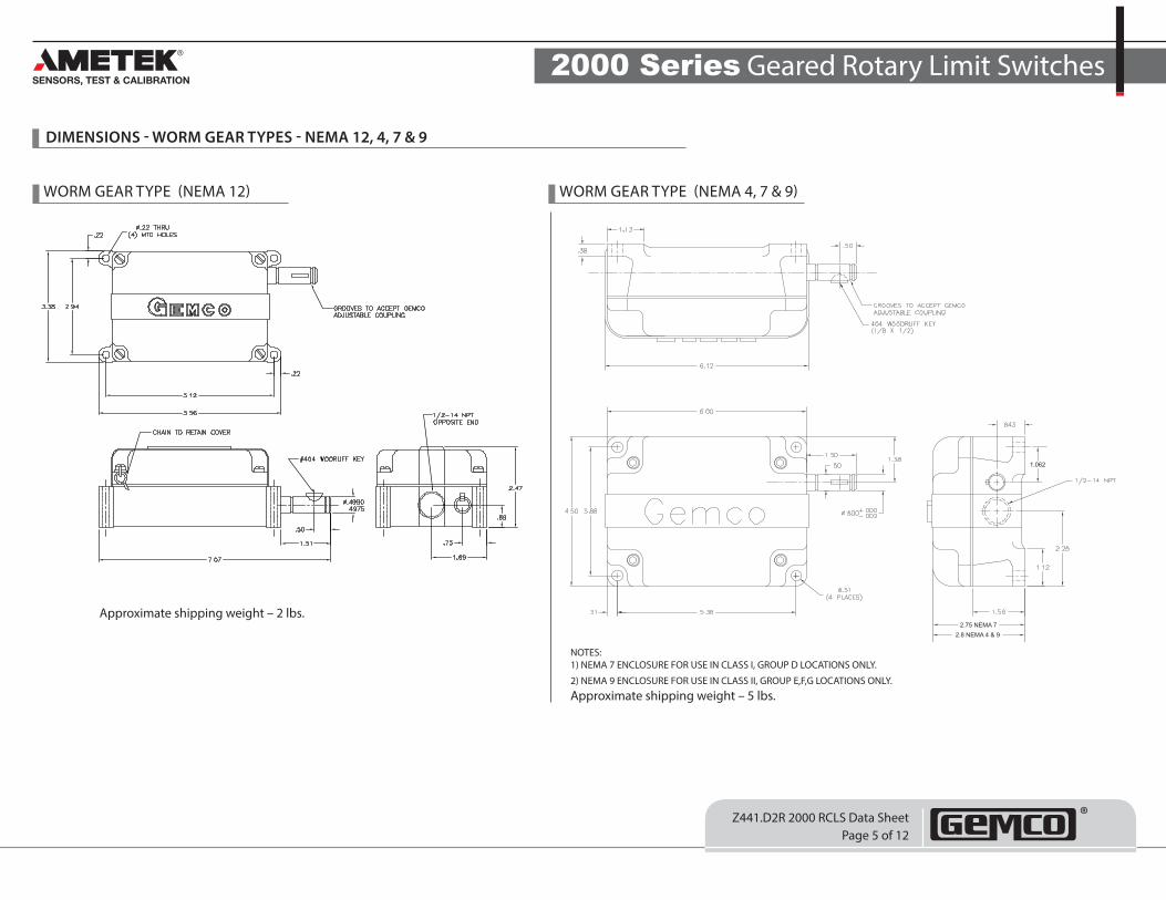
DIMENSIONS - WORM GEAR TYPES - NEMA 12, 4, 7 & 9
2.75 NEMA 72.8 NEMA 4 & 9
1.062
WORM GEAR TYPE (NEMA 12) WORM GEAR TYPE (NEMA 4, 7 & 9)
Approximate shipping weight – 2 lbs.
NOTES:1) NEMA 7 ENCLOSURE FOR USE IN CLASS I, GROUP D LOCATIONS ONLY.
2) NEMA 9 ENCLOSURE FOR USE IN CLASS II, GROUP E,F,G LOCATIONS ONLY.
Approximate shipping weight – 5 lbs.
2000 Series Geared Rotary Limit Switches
Z441.D2R 2000 RCLS Data SheetPage 6 of 12
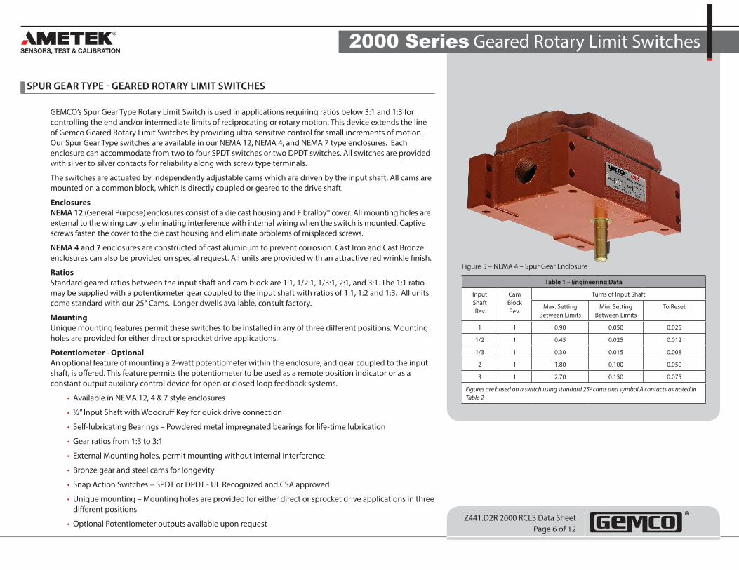
SPUR GEAR TYPE - GEARED ROTARY LIMIT SWITCHES
GEMCO’s Spur Gear Type Rotary Limit Switch is used in applications requiring ratios below 3:1 and 1:3 for controlling the end and/or intermediate limits of reciprocating or rotary motion. This device extends the line of Gemco Geared Rotary Limit Switches by providing ultra-sensitive control for small increments of motion. Our Spur Gear Type switches are available in our NEMA 12, NEMA 4, and NEMA 7 type enclosures. Each enclosure can accommodate from two to four SPDT switches or two DPDT switches. All switches are provided with silver to silver contacts for reliability along with screw type terminals.
The switches are actuated by independently adjustable cams which are driven by the input shaft. All cams are mounted on a common block, which is directly coupled or geared to the drive shaft.
EnclosuresNEMA 12 (General Purpose) enclosures consist of a die cast housing and Fibralloy® cover. All mounting holes are external to the wiring cavity eliminating interference with internal wiring when the switch is mounted. Captive screws fasten the cover to the die cast housing and eliminate problems of misplaced screws.
NEMA 4 and 7 enclosures are constructed of cast aluminum to prevent corrosion. Cast Iron and Cast Bronze enclosures can also be provided on special request. All units are provided with an attractive red wrinkle finish.
Ratios Standard geared ratios between the input shaft and cam block are 1:1, 1/2:1, 1/3:1, 2:1, and 3:1. The 1:1 ratio may be supplied with a potentiometer gear coupled to the input shaft with ratios of 1:1, 1:2 and 1:3. All units come standard with our 25° Cams. Longer dwells available, consult factory.
Mounting Unique mounting features permit these switches to be installed in any of three different positions. Mounting holes are provided for either direct or sprocket drive applications.
Potentiometer - Optional An optional feature of mounting a 2-watt potentiometer within the enclosure, and gear coupled to the input shaft, is offered. This feature permits the potentiometer to be used as a remote position indicator or as a constant output auxiliary control device for open or closed loop feedback systems.
• Available in NEMA 12, 4 & 7 style enclosures
• ½” Input Shaft with Woodruff Key for quick drive connection
• Self-lubricating Bearings – Powdered metal impregnated bearings for life-time lubrication
• Gear ratios from 1:3 to 3:1
• External Mounting holes, permit mounting without internal interference
• Bronze gear and steel cams for longevity
• Snap Action Switches – SPDT or DPDT - UL Recognized and CSA approved
• Unique mounting – Mounting holes are provided for either direct or sprocket drive applications in three different positions
• Optional Potentiometer outputs available upon request
Table 1 – Engineering Data
Input Shaft Rev.
Cam Block Rev.
Turns of Input Shaft
Max. Setting Between Limits
Min. Setting Between Limits
To Reset
1 1 0.90 0.050 0.025
1/2 1 0.45 0.025 0.012
1/3 1 0.30 0.015 0.008
2 1 1.80 0.100 0.050
3 1 2.70 0.150 0.075
Figures are based on a switch using standard 25º cams and symbol A contacts as noted in Table 2
Figure 5 – NEMA 4 – Spur Gear Enclosure
2000 Series Geared Rotary Limit Switches
Z441.D2R 2000 RCLS Data SheetPage 7 of 12
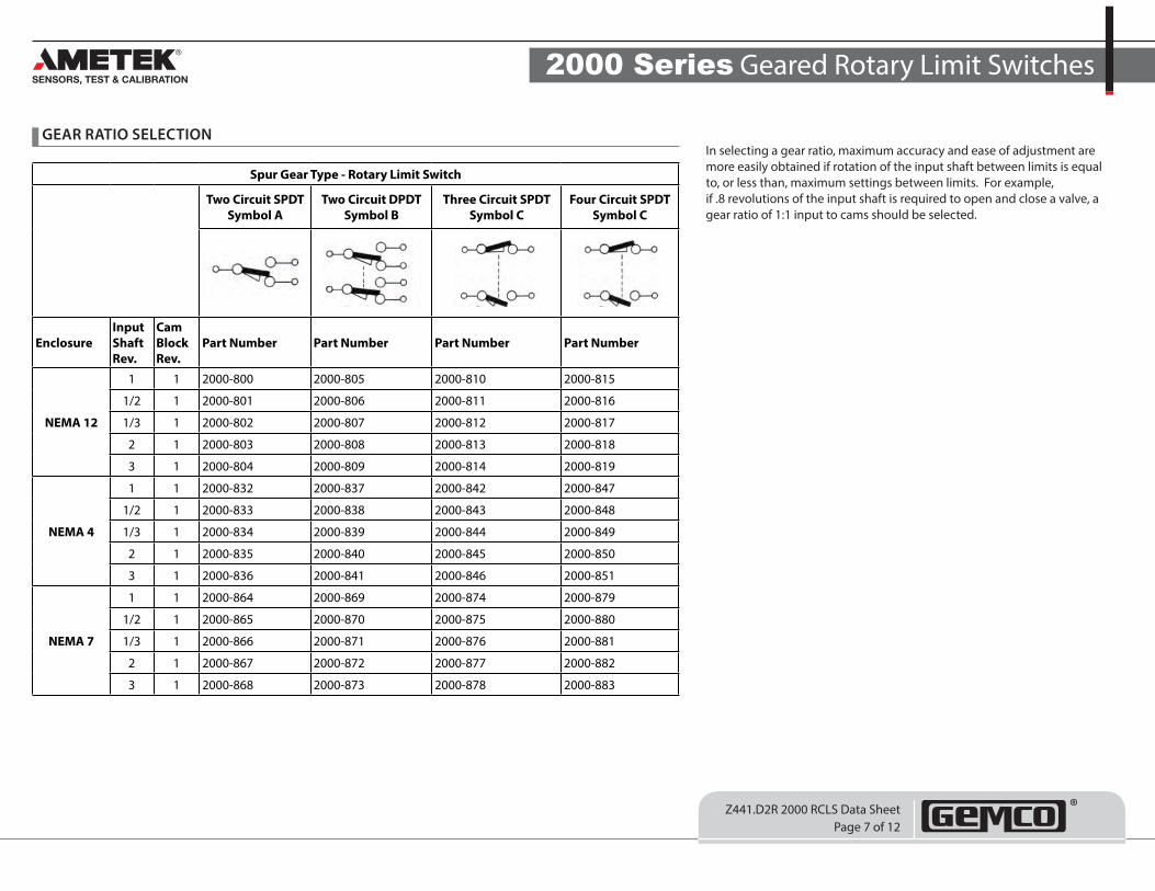
GEAR RATIO SELECTIONIn selecting a gear ratio, maximum accuracy and ease of adjustment are more easily obtained if rotation of the input shaft between limits is equal to, or less than, maximum settings between limits. For example, if .8 revolutions of the input shaft is required to open and close a valve, a gear ratio of 1:1 input to cams should be selected.
Spur Gear Type - Rotary Limit Switch
Two Circuit SPDT Symbol A
Two Circuit DPDT Symbol B
Three Circuit SPDT Symbol C
Four Circuit SPDT Symbol C
EnclosureInput Shaft Rev.
Cam Block Rev.
Part Number Part Number Part Number Part Number
NEMA 12
1 1 2000-800 2000-805 2000-810 2000-815
1/2 1 2000-801 2000-806 2000-811 2000-816
1/3 1 2000-802 2000-807 2000-812 2000-817
2 1 2000-803 2000-808 2000-813 2000-818
3 1 2000-804 2000-809 2000-814 2000-819
NEMA 4
1 1 2000-832 2000-837 2000-842 2000-847
1/2 1 2000-833 2000-838 2000-843 2000-848
1/3 1 2000-834 2000-839 2000-844 2000-849
2 1 2000-835 2000-840 2000-845 2000-850
3 1 2000-836 2000-841 2000-846 2000-851
NEMA 7
1 1 2000-864 2000-869 2000-874 2000-879
1/2 1 2000-865 2000-870 2000-875 2000-880
1/3 1 2000-866 2000-871 2000-876 2000-881
2 1 2000-867 2000-872 2000-877 2000-882
3 1 2000-868 2000-873 2000-878 2000-883
2000 Series Geared Rotary Limit Switches
Z441.D2R 2000 RCLS Data SheetPage 8 of 12
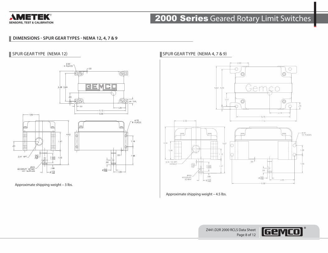
DIMENSIONS - SPUR GEAR TYPES - NEMA 12, 4, 7 & 9
SPUR GEAR TYPE (NEMA 12) SPUR GEAR TYPE (NEMA 4, 7 & 9)
Approximate shipping weight – 3 lbs.
Approximate shipping weight – 4.5 lbs.
2000 Series Geared Rotary Limit Switches
Z441.D2R 2000 RCLS Data SheetPage 9 of 12
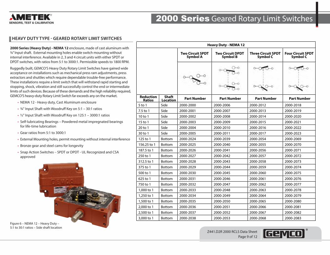
HEAVY DUTY TYPE - GEARED ROTARY LIMIT SWITCHES
2000 Series (Heavy Duty) - NEMA 12 enclosure, made of cast aluminum with ¾” Input shaft. External mounting holes enable switch mounting without internal interference. Available in 2, 3 and 4 circuit units with either SPDT or DPDT switches, with ratios from 5:1 to 3000:1. Permissible speeds to 1800 RPM.
Ruggedly built, GEMCO’S Heavy Duty Rotary Limit Switches have gained wide acceptance on installations such as mechanical press ram adjustments, press extractors and shuttles which require dependable trouble-free performance. These installations require a limit switch that will withstand rapid starting and stopping, shock, vibration and still successfully control the end or intermediate limits of such devices. Because of these demands and the high reliability required, GEMCO’S heavy-duty Rotary Limit Switch far exceeds any on the market.
• NEMA 12 - Heavy duty, Cast Aluminum enclosure
• ¾" Input Shaft with Woodruff Key on 5:1 – 30:1 ratios
• ½" Input Shaft with Woodruff Key on 125:1 – 3000:1 ratios
• Self-lubricating Bearings – Powdered metal impregnated bearings for life-time lubrication
• Gear ratios from 5:1 to 3000:1
• External Mounting holes, permit mounting without internal interference
• Bronze gear and steel cams for longevity
• Snap Action Switches – SPDT or DPDT - UL Recognized and CSA approved
Figure 6 – NEMA 12 – Heavy Duty – 5:1 to 30:1 ratios – Side shaft location
Heavy Duty - NEMA 12
Two Circuit SPDT Symbol A
Two Circuit DPDT Symbol B
Three Circuit SPDT Symbol C
Four Circuit SPDT Symbol C
Reduction Ratios
Shaft Location Part Number Part Number Part Number Part Number
5 to 1 Side 2000-2000 2000-2006 2000-2012 2000-20187.5 to 1 Side 2000-2001 2000-2007 2000-2013 2000-201910 to 1 Side 2000-2002 2000-2008 2000-2014 2000-202015 to 1 Side 2000-2003 2000-2009 2000-2015 2000-202120 to 1 Side 2000-2004 2000-2010 2000-2016 2000-202230 to 1 Side 2000-2005 2000-2011 2000-2017 2000-2023125 to 1 Bottom 2000-2024 2000-2039 2000-2054 2000-2069156.25 to 1 Bottom 2000-2025 2000-2040 2000-2055 2000-2070187.5 to 1 Bottom 2000-2026 2000-2041 2000-2056 2000-2071250 to 1 Bottom 2000-2027 2000-2042 2000-2057 2000-2072312.5 to 1 Bottom 2000-2028 2000-2043 2000-2058 2000-2073375 to 1 Bottom 2000-2029 2000-2044 2000-2059 2000-2074
500 to 1 Bottom 2000-2030 2000-2045 2000-2060 2000-2075
625 to 1 Bottom 2000-2031 2000-2046 2000-2061 2000-2076750 to 1 Bottom 2000-2032 2000-2047 2000-2062 2000-20771,000 to 1 Bottom 2000-2033 2000-2048 2000-2063 2000-20781,250 to 1 Bottom 2000-2034 2000-2049 2000-2064 2000-20791,500 to 1 Bottom 2000-2035 2000-2050 2000-2065 2000-20802,000 to 1 Bottom 2000-2036 2000-2051 2000-2066 2000-20812,500 to 1 Bottom 2000-2037 2000-2052 2000-2067 2000-20823,000 to 1 Bottom 2000-2038 2000-2053 2000-2068 2000-2083
2000 Series Geared Rotary Limit Switches
Z441.D2R 2000 RCLS Data SheetPage 10 of 12
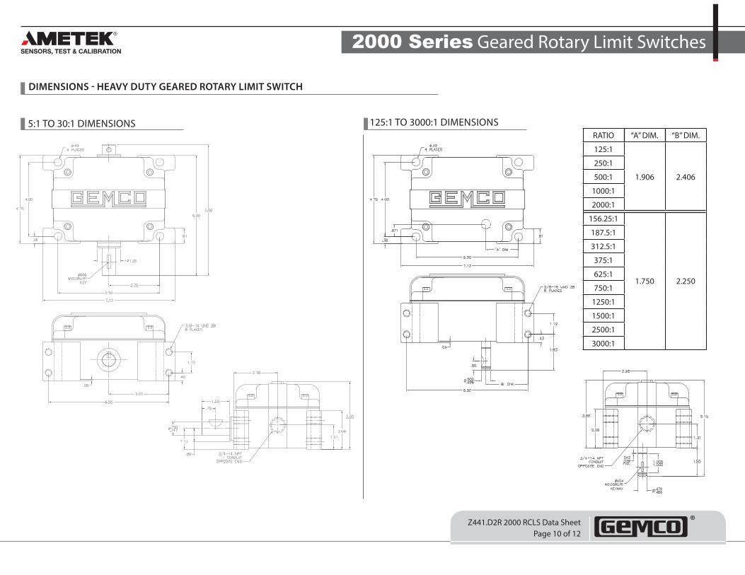
DIMENSIONS - HEAVY DUTY GEARED ROTARY LIMIT SWITCH
5:1 TO 30:1 DIMENSIONS 125:1 TO 3000:1 DIMENSIONSRATIO “A” DIM. “B” DIM.
125:1
1.906 2.406
250:1
500:1
1000:1
2000:1
156.25:1
1.750 2.250
187.5:1
312.5:1
375:1
625:1
750:1
1250:1
1500:1
2500:1
3000:1
2000 Series Geared Rotary Limit Switches
Z441.D2R 2000 RCLS Data SheetPage 11 of 12
SPECIFICATIONS ELECTRICAL SWITCH RATINGS
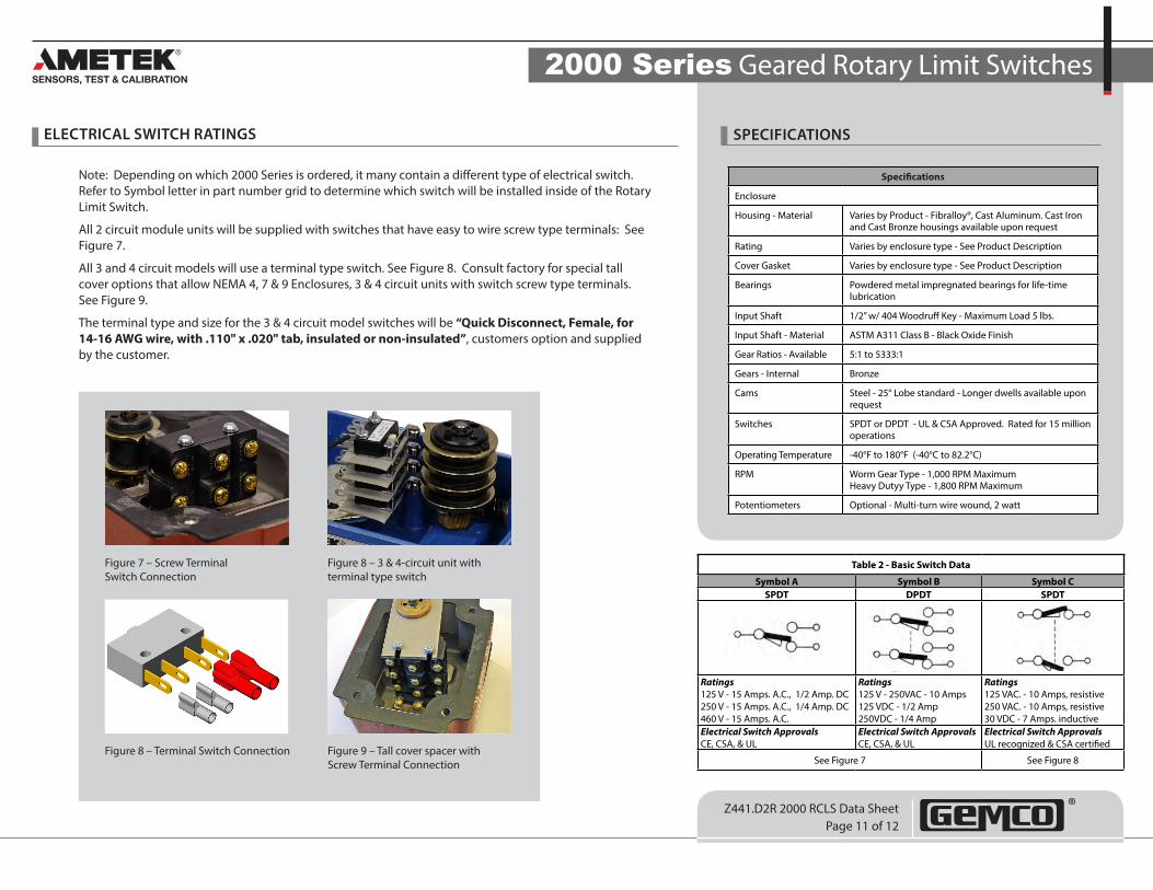
Note: Depending on which 2000 Series is ordered, it many contain a different type of electrical switch. Refer to Symbol letter in part number grid to determine which switch will be installed inside of the Rotary Limit Switch.
All 2 circuit module units will be supplied with switches that have easy to wire screw type terminals: See Figure 7.
All 3 and 4 circuit models will use a terminal type switch. See Figure 8. Consult factory for special tall cover options that allow NEMA 4, 7 & 9 Enclosures, 3 & 4 circuit units with switch screw type terminals. See Figure 9.
The terminal type and size for the 3 & 4 circuit model switches will be “Quick Disconnect, Female, for 14-16 AWG wire, with .110" x .020" tab, insulated or non-insulated”, customers option and supplied by the customer.
Specifications
Enclosure
Housing - Material Varies by Product - Fibralloy®, Cast Aluminum. Cast Iron and Cast Bronze housings available upon request
Rating Varies by enclosure type - See Product Description
Cover Gasket Varies by enclosure type - See Product Description
Bearings Powdered metal impregnated bearings for life-time lubrication
Input Shaft 1/2” w/ 404 Woodruff Key - Maximum Load 5 lbs.
Input Shaft - Material ASTM A311 Class B - Black Oxide Finish
Gear Ratios - Available 5:1 to 5333:1
Gears - Internal Bronze
Cams Steel - 25° Lobe standard - Longer dwells available upon request
Switches SPDT or DPDT - UL & CSA Approved. Rated for 15 million operations
Operating Temperature -40°F to 180°F (-40°C to 82.2°C)
RPM Worm Gear Type - 1,000 RPM Maximum Heavy Dutyy Type - 1,800 RPM Maximum
Potentiometers Optional - Multi-turn wire wound, 2 watt
Figure 7 – Screw Terminal Switch Connection
Figure 8 – 3 & 4-circuit unit with terminal type switch
Figure 8 – Terminal Switch Connection Figure 9 – Tall cover spacer with Screw Terminal Connection
Table 2 - Basic Switch Data
Symbol A Symbol B Symbol CSPDT DPDT SPDT
Ratings 125 V - 15 Amps. A.C., 1/2 Amp. DC 250 V - 15 Amps. A.C., 1/4 Amp. DC 460 V - 15 Amps. A.C.
Ratings 125 V - 250VAC - 10 Amps 125 VDC - 1/2 Amp 250VDC - 1/4 Amp
Ratings 125 VAC. - 10 Amps, resistive 250 VAC. - 10 Amps, resistive 30 VDC - 7 Amps. inductive
Electrical Switch Approvals CE, CSA, & UL
Electrical Switch Approvals CE, CSA, & UL
Electrical Switch Approvals UL recognized & CSA certified
See Figure 7 See Figure 8
2000 Series Geared Rotary Limit Switches
Z441.D2R 2000 RCLS Data SheetPage 12 of 12
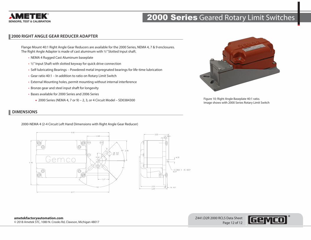
2000 RIGHT ANGLE GEAR REDUCER ADAPTER
Flange Mount 40:1 Right Angle Gear Reducers are available for the 2000 Series, NEMA 4, 7 & 9 enclosures. The Right Angle Adapter is made of cast aluminum with ½” Slotted Input shaft.
• NEMA 4 Rugged Cast Aluminum baseplate
• ½" Input Shaft with slotted keyway for quick drive connection
• Self-lubricating Bearings – Powdered metal impregnated bearings for life-time lubrication
• Gear ratio 40:1 – In addition to ratio on Rotary Limit Switch
• External Mounting holes, permit mounting without internal interference
• Bronze gear and steel input shaft for longevity
• Bases available for 2000 Series and 2006 Series
■ 2000 Series (NEMA 4, 7 or 9) – 2, 3, or 4 Circuit Model – SD0384300 Figure 10: Right Angle Baseplate 40:1 ratio. Image shows with 2000 Series Rotary Limit Switch
2000-NEMA 4 (2-4 Circuit Left Hand Dimensions with Right Angle Gear Reducer)
DIMENSIONS
ametekfactoryautomation.com© 2018 Ametek STC, 1080 N. Crooks Rd, Clawson, Michigan 48017