Embed Size (px)
Citation preview

O P E R AT O R ’ S S A F E T Y A N D S E R V I C E M A N U A L
MBW, Inc.250 Hartford Rd • PO Box 440Slinger, WI 53086-0440Phone: (262) 644-5234Fax: (262) 644-5169Email: [email protected]: www.mbw.com
MBW (UK) Ltd.Units 2 & 3 Cochrane StreetBolton BL3 6BN, EnglandPhone: 01204 387784Fax: 01204 387797
MBW FRANCE S.A.R.L.Phone: +33 (0) 3 44 07 15 96
L18702/ 08.18.AD©MBW, Inc. 2015
Printed in the USA
2 0 0 0 , 2 0 1 8 A P 2 0 0 0 +& 3 5 5 0This manual covers the following serial numbersand higher for each model listed:
2000........................................2070150.
2018........................................2180195.
3550........................................3551200.
V I B R AT O R Y P L AT E S

TA B L E O F C O N T E N T S
SAFETY INFORMATION . . . . . . . . . . . . . . . . . 1
Introduction . . . . . . . . . . . . . . . . . . . . . . . . . . . . . . . . . 1
Safety Precautions . . . . . . . . . . . . . . . . . . . . . . . . . . . 1
Safety Decals . . . . . . . . . . . . . . . . . . . . . . . . . . . . . . . 1
SPECIFICATIONS. . . . . . . . . . . . . . . . . . . . . . . 3
OPERATION . . . . . . . . . . . . . . . . . . . . . . . . . . . 5
Introduction . . . . . . . . . . . . . . . . . . . . . . . . . . . . . . . . . 5
Before Starting & Operating . . . . . . . . . . . . . . . . . . . . 5
Starting Engine . . . . . . . . . . . . . . . . . . . . . . . . . . . . . . 5
Operating . . . . . . . . . . . . . . . . . . . . . . . . . . . . . . . . . . 5
Stopping Engine . . . . . . . . . . . . . . . . . . . . . . . . . . . . . 5
Lifting/Transporting . . . . . . . . . . . . . . . . . . . . . . . . . . . 5
MAINTENANCE . . . . . . . . . . . . . . . . . . . . . . . . 6
Maintenance Schedule . . . . . . . . . . . . . . . . . . . . . . . . 6
Fluid Levels. . . . . . . . . . . . . . . . . . . . . . . . . . . . . . . . . 6
Engine Maintenance . . . . . . . . . . . . . . . . . . . . . . . . . . 6
Engine Speed . . . . . . . . . . . . . . . . . . . . . . . . . . . . . . . 6
Cleaning Plate . . . . . . . . . . . . . . . . . . . . . . . . . . . . . . 6
Belt Adjustment. . . . . . . . . . . . . . . . . . . . . . . . . . . . . . 6
Checking Exciter Oil . . . . . . . . . . . . . . . . . . . . . . . . . . 7
Changing Exciter Oil . . . . . . . . . . . . . . . . . . . . . . . . . . 7
SERVICE . . . . . . . . . . . . . . . . . . . . . . . . . . . . . . 9
Torque Chart . . . . . . . . . . . . . . . . . . . . . . . . . . . . . . . 9
Service Tools . . . . . . . . . . . . . . . . . . . . . . . . . . . . . . . 9
Exciter Removal . . . . . . . . . . . . . . . . . . . . . . . . . . . . . 9
(2000) Exciter Disassembly . . . . . . . . . . . . . . . . . . . . 9
(2000) Exciter Assembly . . . . . . . . . . . . . . . . . . . . . 10
(3550) Exciter Disassembly . . . . . . . . . . . . . . . . . . . 10
(3550) Exciter Assembly . . . . . . . . . . . . . . . . . . . . . 10
Exciter installation . . . . . . . . . . . . . . . . . . . . . . . . . . 11
Parts Replacement Cycles and Tolerances . . . . . . . 11
REPLACEMENT PARTS. . . . . . . . . . . . . . . . . 132000 & 2018 EXCITER ASSEMBLY . . . . . . . . . . . . 14
3550 Exciter Assembly. . . . . . . . . . . . . . . . . . . . . . . 16ENGINE ASSEMBLY 2000/2018 . . . . . . . . . . . . . . . 18ENGINE ASSEMBLY 3550 . . . . . . . . . . . . . . . . . . . 20
ROLLCAGE ASSEMBLY . . . . . . . . . . . . . . . . . . . . . 222018 ASSEMBLY . . . . . . . . . . . . . . . . . . . . . . . . . . . 24
WARRANTY . . . . . . . . . . . . . . . . . . . . . . . . . . 26

CALIFORNIA PROPOSITION 65 WARNINGEngine exhaust and some of its constituents and dust produced during the use of this product contain chemi-cals known in the state of California to cause cancer, birth defects, and other reproductive harm.For more information go to www.P65Warnings.ca.gov
WARNING

- 1 -
S A F ET Y I N F O R M AT I O N
Introduction
This Safety Alert Symbol is used to call attentionto items or operations which may be dangerousto those operating or working with this equipment.The symbol can be found throughout this manual
and on the unit. Please read these warnings and cautions,along with all decals, carefully before attempting to operatethe unit. Make sure every individual who operates or workswith this equipment is familiar with all safety precautions.
WARNINGGENERAL WARNING. Indicates informationimportant to the proper operation of the equipment.Failure to observe may result in damage to theequipment and/or severe bodily injury or death.
CAUTIONGENERAL CAUTION. Indicates informationimportant to the proper operation of the equipment.Failure to observe may result in damage to theequipment.
Safety Precautions
LETHAL EXHAUST GAS: An internalcombustion engine discharges carbonmonoxide, a poisonous, odorless, invisiblegas. Death or serious illness may result ifinhaled. Operate only in a properly ventilatedarea. NEVER OPERATE IN A CONFINEDAREA!
DANGEROUS FUELS: Use extreme cautionwhen storing, handling and using fuels, asthey are highly volatile and explosive in vaporstate. Do not add fuel while engine is running.Stop and cool the engine before adding fuel.DO NOT SMOKE!
SAFETY GUARDS: It is the owner'sresponsibility to ensure that all guards andshields are in place and in working order.
IGNITION SYSTEMS: Breakerless, magneto,and battery ignition systems can cause severeelectrical shocks. Avoid contacting these unitsor their wiring.
SAFE DRESS: Do not wear loose clothing,rings, wristwatches, etc. near machinery.
NOISE PROTECTION: Wear OSHA specifiedhearing protection devices.EYE PROTECTION: Wear OSHA specifiedeye shields, safety glasses, and sweat bands.
FOOT PROTECTION: Wear OSHA specifiedsteel-tipped safety shoes.HEAD PROTECTION: Wear OSHA specifiedsafety helmets.
OPERATOR: Keep children and bystandersoff and away from the equipment.
DUST PROTECTION: Machining, crushing orhandling of stone, concrete, masonry, metaland other materials may generate dust, mistand fumes containing chemicals such as
silica, known to cause serious or fatal injury or illness, suchas respiratory disease, silicosis, cancer, birth defects, orother reproductive harm.• Control dust, mist and fumes at the source where possible. Water should be used to control dust whenever feasible.• Use good work practices and follow the recommendationsof the manufacture, OSHA/NIOSH and other occupationaltrade associations.• When hazards cannot be eliminated the operator and anybystanders should always wear a OSHA specified respiratorfor materials being handled.
REFERENCES: For details on safety rules and regulationsin the United States, contact your local Occupational Safetyand Health Administration (OSHA) office. Equipmentoperated in other countries must be operated and servicedin accordance and compliance with any and all safetyrequirements of that country. The publication of these safetyprecautions is done for your information. MBW does not bythe publication of these precautions, imply or in any wayrepresent that these are the sum of all dangers present nearMBW equipment. If you are operating MBW equipment, it isyour responsibility to insure that such operation is in fullaccordance with all applicable safety requirements andcodes. All requirements of the United States FederalOccupational Safety and Health Administration Act must bemet when operated in areas that are under the jurisdictionof that United States Department.
Safety Decals
Carefully read and follow all safety decals. Keep them ingood condition. If decals become damaged, replace asrequired. If repainting the unit, replace all decals. Decals areavailable from authorized MBW distributors. Order the decalset listed on the following page(s).

- 2 -
20019
Wear approved hearing protection, foot protection, eye protection and head protection.
STOP
Read the Operating Instructions before operating this piece of equipment.
Keep unauthorized and untrained people away from this equipment.ROTATING & MOVING PARTS! Make sure all guards and safety devices are in place.
SHUT OFF the motor before servic-ing or cleaning.
DO NOT RUN in an enclosed area. The engine produces carbon monoxide, a POISONOUS GAS.
Failure to comply could result in serious bodily injury.
CAUTION
Avoid breathing dust from operating machine, wear OSHA specified dust mask/respirator.
CAUTIONAP3550=254 lbs (115 kg)GP5800=300 lbs (136 kg)
16402
GP2000=165 lbs (75 kg)AP2000=193 lbs (88 kg)GP3550=226 lbs (103kg)
Machine may fall and cause injury or damage if lifted improperly. Lift by handles or rollcage only.
19791
WARNINGOPERATION OF THIS EQUIPMENT MAY CREATE SPARKS THAT CAN START FIRES AROUND DRY VEGETATION. A SPARK ARRESTER MAY BE REQUIRED. THE OPERATOR SHOULD CONTACT LOCAL FIRE AGENCIES FOR LAWS OR REGULATIONS RELATING TO FIRE PREVENTION
��������������
�����
12573
WARNING
ROTATING PARTS can crush and cut.Keep hands away!
MODEL SERIAL NO
SERIAL NOMODEL
M-B-W INC.SLINGER, WI 53086
GROUND POUNDER DIV.
18724
GP2000/AP2000
GP2000/AP2000
����� ��������������� ��
�� �����������������
�� ���� !���"#�"��
$� ����������������%#&'��������'#(���)����*�)��+�������*�
,� ����)�&�))����#&)�%#(�
-� �!���.)#&)�&�&����
/� � )�&�.)#&)���0�����������1�&�)!&��)�&�))���)���*�����.�)����
2� 3!&�������&#)���1�%�����4��..�"������+#����.���)���*1�'#4�'!'���'�#�)�����#.�+����&�#���*�
5� ���.)��0��)!&��)�&�))���)���*�����.�)���1��!.���������.)���.%�)��1����.�� !���"#�"��
�$,5�
Safety Decals (Decal Set #12100)
19791
16402
20019
01066
12500
12573
13482
18724 - 200019451 - 201818703 - 3550
20526 - 200020527 - 3550
21058
12500
21059 - 200021060 - 3550
21742
21742
21742
21742
WARNINGOperating, servicing and maintaining this equipment can expose you to chemicals, including engine exhaust, phthalates and lead, which are known to the state of California to cause cancer and birth defects or other reproductive harm. Avoid breathing engine exhaust. Do not operate equipment in confined areas.For more information go to www.P65Warnings.ca.gov
21820
21820

- 3 -
S P E C I F I C AT I O N S
AP2000 GP2000 AP2018 GP2018CENTRIFUGAL FORCE 2475 lbf (1123 kg) 3250 lbf (1474 kg) 2475 lbf (1123 kg) 3250 lbf (1474 kg)
EXCITER (VPM) 4400 5050 4400 5050
TRAVEL SPEED 90 ft/min(28 m/min) 120 ft/min(36 m/min) 90 ft/min(28 m/min) 120 ft/min(36 m/min)
COMPACTION DEPTH 12 in (30 cm) 14 in (36 cm) 12 in (30 cm) 14 in (36 cm)
WIDTH x LENGTH x HEIGHT20 x 22 x 21 in
(51 x 56 x 53 cm)20 x 22 x 21 in
(51 x 56 x 53 cm)20 x 22 x 18 in
(51 x 56 x 46 cm)20 x 22 x 18 in
(51 x 56 x 46 cm)
OPERATING WEIGHT (HONDA)
168 lbs (76 kg) no water193 lbs (88 kg) full water
165 lbs (75 kg)168 lbs (76 kg) no water178 lbs (81 kg) full water
163 lbs (74 kg)
ENGINE SPEED 3400 (RPM) 3400 (RPM) 3400 (RPM) 3400 (RPM)
WATER TANK CAPACITY 3 gal (11.3 l) 1 gal (4)
NOISE LEVEL 84 - 94 dBA 84 - 94 dBA 84 - 94 dBA 84 - 94 dBA
ENGINE OPTIONS HONDA GX160 (163 cm)³
AP2018
Specifications subject to change without notice.
- No universal method or formula has been accepted for determining “Compaction Force”. All manufactures employtheir own method or formula.

- 4 -
S P E C I F I C AT I O N S
AP3550 GP3550CENTRIFUGAL FORCE 3550 lbf (1610 kg) 3550 lbf (1610 kg)
EXCITER (VPM) 4400 4400
TRAVEL SPEED 110 ft/min(34 m/min) 110 ft/min(34 m/min)
COMPACTION DEPTH 18 in (46 cm) 18 in (46 cm)
WIDTH x LENGTH X HEIGHT21 x 22 x 22.2 in
(53 x 56 x 56.3 cm)21 x 22 x22.2 in
(53 x 56 x 56.3 cm)
OPERATING WEIGHT (HONDA)229 lbs (104 kg) no water254 lbs (115 kg) full water
226 lbs (103 kg)
ENGINE SPEED 3400 (RPM) 3400 (RPM)
WATER TANK CAPACITY 3 gal (11.3 l)
NOISE LEVEL 84 - 94 dBA 84 - 94 dBA
ENGINE OPTIONS HONDA GX160 (163 cc)³
Specifications subject to change without notice.
- No universal method or formula has been accepted for determining “Compaction Force”. All manufactures employtheir own method or formula.

- 5 -
����������� ��
O P E R AT I O N
Introduction
MBW equipment is intended for use in very severeapplications. They are powered by four cycle engines andare available in different sizes and a selection of engines.
This parts manual contains only standard parts. Variationsof these parts as well as other special parts are not included.Contact your local MBW distributor for assistance inidentifying parts not included in this manual.
Before Starting & Operating
• HANDLE INSTALLATION - Refer to ROLLCAGEASSEMBLY, page 23. Install handle by removing handleattachment nuts. Reinstall handle attachment nutthrough the handle bushings from the inside in. Makesure nylon bushings inside the handle stay in place.
• REMEMBER! It is the owner’s responsibility tocommunicate information on the safe use and properoperation of this unit to the operators.
• Review ALL of the Safety Precautions listed on page 1 ofthis manual.
• Familiarize yourself with the operation of the machineand confirm that all controls function properly.
• Know how to STOP the machine in case of anemergency.
• Make sure hands, feet, and clothing are at a safedistance from any moving parts.
• OIL LEVEL - Check the oil level in the engine. For moreinformation see “Lubrication” under the respectiveengine’s “Owners Manual” or the Maintenance section ofthis manual.
• AIR CLEANER - Check to ensure element is in goodcondition and properly installed.
• FUEL SUPPLY - The engines on MBW equipmentrequire an automotive grade of clean, fresh, unleadedgasoline.
• FUEL FILTER - If clogged or damaged, replace.
Starting Engine
1. Open fuel valve.
2. Turn engine switch to “ON”.
3. Set throttle to idle.
4. Choke engine if necessary (you may not need tochoke a warm engine).
5. Pull starter rope repeatedly until engine starts.
6. Move choke lever to open position.
7. Allow engine to warm up for one or two minutes.
Operating
1. Open throttle fully.
2. Compactor will begin vibrating and moving in aforward direction.
3. Maximum compaction of soil has been reached whenexcessive kickback is noticed in the compactor. Thenumber of passes needed to reach compaction leveldesired will depend on soil type and moisture.
4. When using the compactor on asphalt use the watersprinkling system to keep the plate bottom formadhering to the hot asphalt.
Stopping Engine
1. Move throttle to idle position.
2. Let engine idle for one or two minutes.
3. Turn switch on engine to “STOP” position.
4. Turn off fuel valve.
Lifting/Transporting
1. The unit can be lifted by the handles on the sides ofthe unit or by the roll cage.
2. The unit must be transported in the upright position.DO NOT lay machine on itsside or top.
3. Secure or tie down unitusing the lift handles or rollcage.
WARNINGAlways stop the engine before:
Adding fuel.
Leaving the equipment unattended for anyamount of time.
Before making any repairs or adjustments to themachine.

M A I N T E N A N C E
WARNINGAlways exercise the stopping procedure beforeservicing or lubricating the unit.
After servicing the unit, replace and fasten allguards, shields, and covers to their originalpositions before resuming operation.
CAUTIONAlways verify fluid levels and check for leaks afterchanging fluids.
Do not drain oil onto ground, into open streams,or down sewage drains.
Maintenance Schedule
1. Check all hardware after the first 5 hours of use, then follow the maintenance schedule.
Fluid Levels
1. MBW #01058----- 6-Pack (8 oz. bottles)MBW #17320----- 1 Quart (32 oz.)MBW #20186------1 Bottle (8 oz.)
Engine Maintenance
Refer to the engine Owner’s Manual for maintenanceintervals and procedures.
Engine Speed
1. Engine speed is factory set according to the speedslisted in the Specifications section of this manual. Donot tamper with the governor setting.the governorestablishes safe operating limits which must not beexceeded.
2. Refer to the engine Owner’s Manual for procedure onsetting operating and idle speed.
3. The engine operating speed should be set to 3400RPM.
4. The engine idle speed must not exceed 1800 rpm. Ifthe idle speed is greater than 1800 RPM the clutchmay not disengage.
Cleaning Plate
Remove any excess debris which may get into the housingof the unit.
Belt Adjustment
If any belt stretch develops follow these steps:Reference engine assembly page.
1. Remove 4 flange bolts securing roll cage assembly toengine deck and remove roll cage assembly. Seefigure 1.
SYSTEM MAINTENANCE EACH USEEVERY 50
HOURSEVERY 250
HOURSYEARLY
Engine Refer to engine operator/owner manual X
Exciter Check oil level X
Check for oil leaks X
Change oil X X
Tighten Bolts1 X X
Hardware Check and tighten as needed1 X X
Shock mounts Check for cracks or tears X X
SYSTEM FLUID VOLUME RECOMMENDED OIL
Exciter6 oz (2000 Plate)
8 oz. (3550 Plate)MBW Ground Pounder® Exciter Oil1
Engine Refer to engine operator/owner manual
- 6 -

�����������������������������������
����������������
�����������
�����������������
�����
������ ���
���
� �����
������ ���
��������
2. Apply moderate thumb pressure to belt about halfway between pulleys. When properly adjusted thebelt should deflect approximately 3/8” (9mm). If thebelt is adjusted correctly reinstall belt guard andhardware.
3. To adjust belt tension loosen (do not remove) the (4)engine bolts.
4. Push engine towards the back of the plate. Whileholding pressure on the engine retighten the (4)engine bolts.
5. Recheck belt tension as described in step 2 andreadjust if necessary until the proper tension isreached.
6. Reinstall roll cage assembly.
Checking Exciter Oil
WARNINGExciter and oil is hot after machine has beenrunning. Allow machine to cool before servicingunit.
1. Let exciter cool before checking oil.
2. Place plate on a level surface.
3. Remove roll cage assembly by removing (4) flangescrews securing roll cage to engine deck. If machine
is equipped with water tank disconnect hose fromspray bar on front of plate. Now entire roll cageassembly, including roll cage, handle, water tank andbelt guard, can be removed (see Figure 1).
4. Clean all dirt and debris from exciter to preventcontamination of exciter oil.
5. Remove pipe plug from top of exciter housing.
6. Rotate exciter shaft so a metal dip stick can beinserted into exciter (see Figure 2).
7. Place a clean metal rod through the oil fill hole asshown in figure 2.
8. Exciter should have approximately 3/4” (2000 plate)7/8 to 1” (3550 plate) oil.
9. If oil need to be added, refer to Fluid Levels page ofthis section for type of oil to be used. DO NOTOVERFILL, over filling can cause excessive heat inexciter.
10. Apply pipe sealant to pipe plug and reinstall into topof exciter housing.
11. Reinstall roll cage assembly and re-attach hose tospray bar.
Changing Exciter Oil
WARNINGExciter and oil is hot after machine has beenrunning. Allow machine to cool before servicingunit.
1. Let exciter cool before changing oil.
2. Remove roll cage assembly by removing (4) flangescrews securing roll cage to engine deck. If machineis equipped with water tank disconnect hose fromspray bar on front of plate. Now entire roll cageassembly, including roll cage, handle, water tank andbelt guard, can be removed (see Figure 1).
- 7 -

�������� �����
��!�� �� ��������"� ������������������
#$��%����������&
� ����
�������
��������������� ��
3. Remove 1/2” hex head cap screws and lock washersfrom side of bottom plate. Remove belt and enginedeck assembly. Refer to figure 3
4. Clean all dirt and debris from exciter to preventcontamination of exciter oil.
5. Remove pipe plug from top of exciter housing. Rotateexciter shaft 90as shown in figure 2. Extract oil frombottom of exciter with a vacuum pump. If a vacuumpump is not available tilt plate housing upside downto drain oil from housing.
6. (Optional 3550 Only) Remove oil drain screw andbrass washer from exciter rear cover. Tilt bottom
plate housing onit’s side to drain
oil from housing. After draining oil, return bottom platehousing to the upright position and replace oil drainscrew and brass washer.
7. Return plate housing to the upright position.
8. Fill exciter with MBW Ground Pounder® exciter oil tolevel specified in the Fluid Levels section of thismanual.
9. Apply pipe sealant to pipe plug and reinstall into topof exciter housing.
10. Reinstall engine deck assembly, belt and roll cageassembly. If equipped with water tank reattach hoseto spray bar.
- 8 -

S E R V I C E
Assembly and disassembly should be performed by aservice technician who has been factory trained on MBWequipment. The unit should be clean and free of debris.Pressure washing before disassembly is recommended.
• Prior to assembly, wash all parts in a suitable cleaner orsolvent.
• Check moving parts for wear and failure. Refer to theReplacement section in this manual for tolerance andreplacement cycles.
• All shafts and housings should be oiled prior to pressingbearings. Also, ensure that the bearings are pressedsquare and are seated properly.
• All bearings should be replaced when rebuilding anyexciter or gearbox.
• All gaskets and seals should be replaced after anydisassembly.
Torque Chart
Service Tools
Exciter Removal
1. Remove roll cage assembly, engine deck assemblyand belt. Refer to Changing Exciter Oil, page 7.
2. Remove (4) 5/8-11 exciter bolts, washers, lockwashers and nuts. If unit has exciter shims (7) makenote of location to assure proper placement duringreassembling.
3. Clean exciter and drain oil as described in ChangingExciter Oil section of this manual before proceedingwith disassembly.
(2000) Exciter Disassembly
Refer to 2000 & 2018 EXCITER ASSEMBLY, page 15.for exciter disassembly.
1. Remove flange screw (#23) and washer (#8)securing the pulley (19) to the exciter shaft (#20).
2. Slide pulley off of exciter shaft. be sure not to loseshaft key (#17).
3. Remove 6 flange screws (#23) from rear cover plate(#2) and remove cover, opposite of pulley end.
4. Support exciter assembly on outside diameter ofexciter housing (#1) and press exciter shaft out ofhousing.
5. Remove 6 flange screws (#22) from front cover plate(#18) and remove front cover.
Note: If bearings have failed and need to be replacethen proceed with bearing removal steps. Ifbearings do not need replacing skip to step #9.
6. Support exciter housing (#1) and press out frontbearing (#4).
7. Remove front bearing (#4) inner race from excitershaft by supporting O.D. of race and pressing excitershaft thru.
8. Remove snap ring (#6) and press rear bearing (#5)off of shaft (#20).
9. When reassembling always replace, oil seal (#13)and front & rear cover gaskets (#10 & #11).
SIZE GRADE 2 GRADE 5 GRADE 8
1/4-20 49 in•lbs 76 in•lbs 9 ft•lbs
1/4-28 56 in•lbs 87 in•lbs 10 ft•lbs
5/16-18 8 ft•lbs 13 ft•lbs 18 ft•lbs
5/16-24 9 ft•lbs 14 ft•lbs 20 ft•lbs
3/8-16 15 ft•lbs 23 ft•lbs 33 ft•lbs
3/8-24 17 ft•lbs 26 ft•lbs 37 ft•lbs
7/16-14 24 ft•lbs 37 ft•lbs 52 ft•lbs
7/16-20 27 ft•lbs 41 ft•lbs 58 ft•lbs
1/2-13 37 ft•lbs 57 ft•lbs 80 ft•lbs
1/2-20 41 ft•lbs 64 ft•lbs 90 ft•lbs
9/16-12 53 ft•lbs 82 ft•lbs 115 ft•lbs
5/8-11 73 ft•lbs 112 ft•lbs 159 ft•lbs
5/8-18 83 ft•lbs 112 ft•lbs 180 ft•lbs
3/4-16 144 ft•lbs 200 ft•lbs 315 ft•lbs
1-8 188 ft•lbs 483 ft•lbs 682 ft•lbs
1-14 210 ft•lbs 541 ft•lbs 764 ft•lbs
1-1/2-6 652 ft•lbs 1462 ft•lbs 2371 ft•lbs
M 6 3 ft•lbs 4 ft•lbs 7 ft•lbs
M 8 6 ft•lbs 10 ft•lbs 18 ft•lbs
M 10 10 ft•lbs 20 ft•lbs 30 ft•lbs
CONVERSIONS
in•lbs x 0.083 = ft•lbs
ft•lbs x 12 = in•lbs
ft•lbs x 0.1383 = kg•m
ft•lbs x 1.3558 = N•m
Part No. Description
17320 Ground Pounder® Exciter Oil
01629 Rubber Test Mat
12100 Decal Set
- 9 -
(2000) Exciter Assembly
Refer to 2000 & 2018 EXCITER ASSEMBLY, page 15.for exciter disassembly.
1. Prior to assembly, clean all parts in a suitable solventor cleaning solution. When a complete disassemblyis done it is recommended that all seals, gaskets andbearings are replaced.
Note: If replacing bearings proceed to step #2, if notreplacing bearings skip to step #6.
2. Press front bearing (#4) inner race onto exciter shaft,pulley end.
3. Press front bearing (#4) into exciter housing (#1).
4. Press rear bearing (#5) onto exciter shaft, oppositepulley end, use care to press on I.D. of bearing only.
5. Install snap ring (#6) onto exciter shaft.
6. Press exciter shaft assembly into exciter housing(#1). Use care to properly support O.D. of housingand guide shaft into bearing already in housing.
7. Press oil seal (#13) into front cover (#18), seal to bepress in until bottoming out on inside flange of frontcover.
8. Install new gasket (#10), front cover (#18) and 6flange screws (#22). Torque flange screws to 13 ft.-lbs.
9. Install new gasket (#11), rear cover (#2) and 6 flangescrews (#23). Torque flange screws to 13 ft.-lbs.
10. Grease oil lip seal (#13) and exciter shaft. Install key(#17) on exciter shaft and slide pulley (#19) ontoshaft.
11. Install washer (#8) and flange screw (#23), torqueflange screw to 13 ft.-lbs.
12. Fill exciter with MBW Ground Pounder® exciter oil tolevel specified in the Fluid Levels section of thismanual.
(3550) Exciter Disassembly
Refer to 3550 Exciter Assembly, page 17. for exciterdisassembly.
1. Remove flange screw (#24) and washer (#10)securing the pulley (#19) to the exciter shaft (#20).
2. Slide pulley off of exciter shaft. be sure not to loseshaft key (#17).
Note: To aid in removal of rear cover you will needtwo 5/16-18 bolts, minimum grade 5.
3. Remove 6 flange screws (#24) from rear cover plate(#2). To press rear cover (#2) off of housing, threadtwo 5/16-18 grade 5 bolts into thread holes on cover.Turn bolts in with wrench or ratchet to press coverout. When pressing cover off try to keep even
pressure on both side to ensure cover comes outstraight.
4. Support exciter assembly on outside diameter ofexciter housing (#1) and press exciter shaft out ofhousing.
5. Remove 6 flange screws (#23) from front cover plate(#18) and remove front cover.
Note: If bearings have failed and need to be replacethen proceed with bearing removal step 6. Ifbearings do not need replacing skip to step #9.
6. Support exciter housing (#1) and press out frontbearing (#8) from inside out.
7. Remove retainer plate (#3) by removing 2 cap screws(#22).
8. Remove snap ring (#6).
9. Remove bearing (#7) from rear cover (#2) with 1/4”punch.Tap the bearing out thru the holes for capsscrews (#22). Be sure to alternate between holes toavoid cocking the bearing.
10. Remove snap ring (#5).
11. Remove bearing (#7) inner race from exciter shaft bysupporting O.D. of race and pressing exciter shaftthru.
12. When reassembling always replace sealing washer(#10), oil seal (#13) and front & rear cover gaskets(#11 & #12).
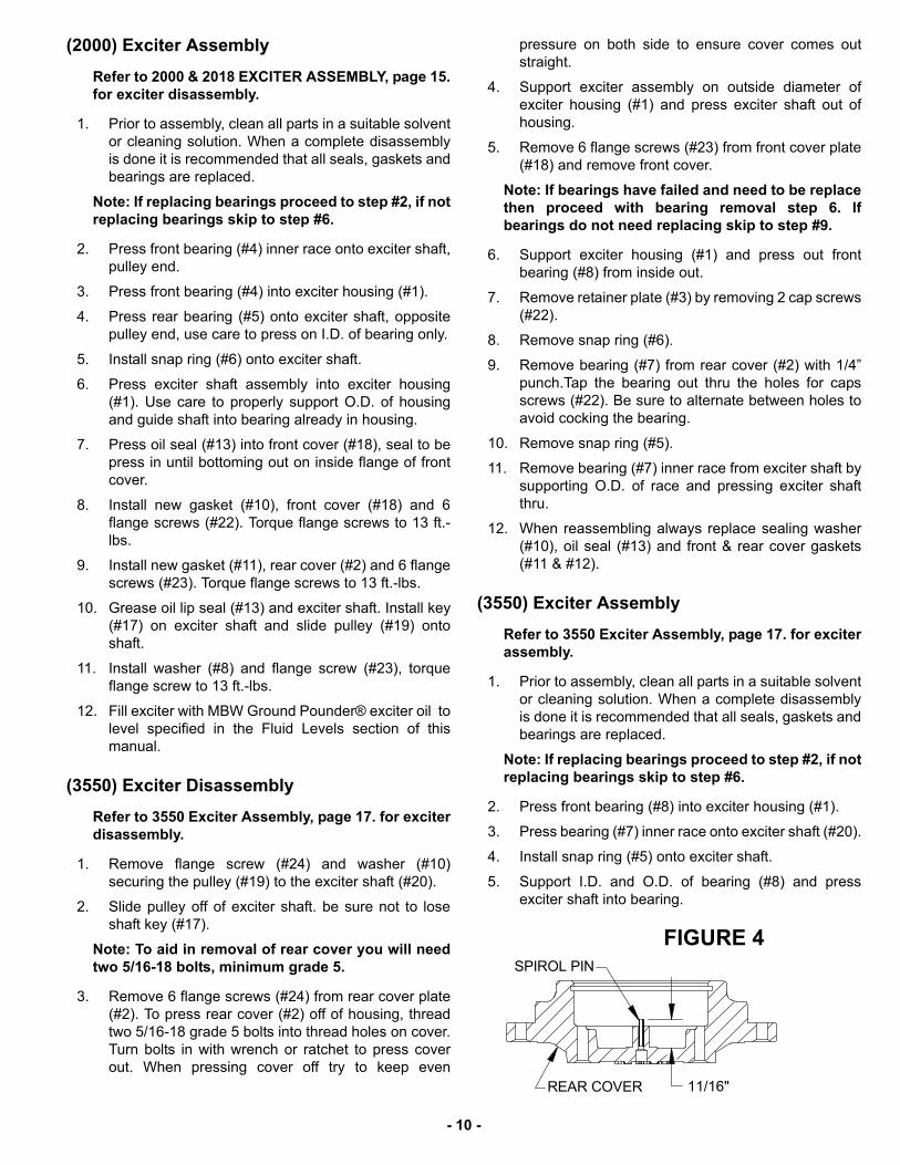
(3550) Exciter Assembly
Refer to 3550 Exciter Assembly, page 17. for exciterassembly.
1. Prior to assembly, clean all parts in a suitable solventor cleaning solution. When a complete disassemblyis done it is recommended that all seals, gaskets andbearings are replaced.
Note: If replacing bearings proceed to step #2, if notreplacing bearings skip to step #6.
2. Press front bearing (#8) into exciter housing (#1).
3. Press bearing (#7) inner race onto exciter shaft (#20).
4. Install snap ring (#5) onto exciter shaft.
5. Support I.D. and O.D. of bearing (#8) and pressexciter shaft into bearing.
� ���������������
������� ����(�
- 10 -

6. Check felt filter (#9) to be sure it is not blocked ordeteriorating, Replace if damaged.
7. Check and set end of spirol pin (#21) to be 11/16”from inside of rear cover (#2). See Figure 4.
8. Press bearing (#7) into rear cover (#2) and installsnap ring (#6) and gasket (#12).
Note: To aid in assembly of rear cover you will needthree, 5/16-18 x 2-1/2 minimum length bolts, to aid inalignment of rear cover.
9. Apply oil to I.D. of exciter housing and O.D. of rearcover.
10. Set rear cover (#2) and new gasket (#12) on exciterhousing and install three alignment bolts into exciterhousing.
CAUTIONBe sure that the inner bearing race is properlyaligned to slide into the bearing. If proper align-ment is not maintained the shaft may push thefront bearing out of the housing.
11. Carefully press or tap the rear cover (#2) down toseat on the exciter housing. Use care to keep coverstraight when installing to prevent damaging housingor cover.
12. Remove the three alignment bolts and install sixflange screws (#24) securing the rear cover. Torqueflange screws to 13 ft.-lbs.
13. Use medium strength thread lock when installingretainer plate (#3) with 2 cap screws (#33).
14. Install oil drain cap screw (#22) and brass washer(#25).
15. Press oil seal (#13) into front cover (#18), Seal to bepress in until flush with front cover.
16. Install sealing washer (#10).
17. Install new gasket (#23), front cover (#11) and 6flange screws (#18). Torque flange screws to 13 ft.-lbs.
18. Install new gasket (#12), rear cover (#2) and 6 flangescrews (#22). Torque flange screws to 13 ft.-lbs.
19. Grease oil lip seal (#13) and exciter shaft. Install key(#17) on exciter shaft and slide pulley (#19) ontoshaft.
20. Install washer (#10) and flange screw (#24), torqueflange screw to 13 ft.-lbs.
21. Fill exciter with MBW Ground Pounder® exciter oil tolevel specified in the Fluid Levels section of thismanual.
Exciter installation
Refer to exciter assembly pages for each unit.
1. Clean exciter mounting bars on bottom plate. If unitwas equipped with exciter shims (3) replace tooriginal position and set exciter assembly in place onmounting bars.
2. Check to make sure exciter sits flat on mounting bars,if not shim (3) as needed.
3. Install 4 5/8-11 exciter bolts, washers, lock washers,and 5/8-11 nuts. Torque exciter bolts to 150 ft.-lbs.
4. Reinstall engine deck, belt and roll cage assembly. Ifequipped with water tank reattach hose to spray bar.Adjust belt as describer in Belt Adjustment section ofthis manual.
Parts Replacement Cycles and Tolerances
BearingsReplace anytime a bearing is rough, binding, discolored or removed from housing orshaft.
Clutch Replace clutch if it does not disengage below 1800 rpm.
Engine Components Refer to your engine manufacturer’s Owner’s Manual.
HardwareReplace any worn or damaged hardware as needed. Replacement hardware shouldbe grade 5 and zinc plated unless otherwise specified.
Safety Decals Replace if they become damaged or illegible.
Seals & Gaskets Replace if a leak is detected and at every overhaul or tear down.
V-Belts Replace if cracked, torn, or stretched to the point the belt won’t tension properly.
Exciter OilReplace once every season or every 250 hours. Use 6 oz. (2000 plate), 8 oz. (3550plate) Ground Pounder ® exciter oil.
- 11 -

- 12 -
This page intentionally left blank.

- 13 -
MBW, Inc.250 Hartford Rd • PO Box 440Slinger, WI 53086-0440Phone: (262) 644-5234Fax: (262) 644-5169Email: [email protected]: www.mbw.com
MBW (UK) Ltd.Units 2 & 3 Cochrane StreetBolton BL3 6BN, EnglandPhone: 01204 387784Fax: 01204 387797
Contact Information
MBW FRANCE S.A.R.L.Phone: +33 (0) 3 44 07 15 96
R E P L A C E M E N T PA R T S
The warranty is stated in this book on page 26. Failure toreturn the Warranty Registration Card renders the warrantynull and void.
MBW has established a network of reputable distributors/dealers with trained mechanics and full facilities formaintenance and rebuilding, and to carry an adequate partsstock in all areas of the country. Their sales engineers areavailable for professional consultation. If you cannot locatean MBW distributor in your area, contact MBW or one of ourSales Branches listed below.
When ordering replacement parts, be sure to have thefollowing information available:
• Model and Serial Number of machine when orderingMBW parts
• Model and Serial Number of engine when orderingengine parts
• Part Number, Description, and Quantity
• Company Name, Address, Zip Code, and PurchaseOrder Number
• Preferred method of shipping
REMEMBER - You own the best! If repairs are needed,use only MBW parts purchased from authorizedMBW distributors.
The unit’s serial number can be found in the followinglocations:
• The model/serial number decal is located on the deckbehind the engine.
• The serial number is stamped on the engine deck in theback left corner, top of exciter housing and on bottomplate exciter mounting bar.
Write Model Number here
Write Serial Number here
�������������
����������������

- 14 -
2000 & 2018 EXCITER ASSEMBLY

- 15 -
ITEM PART NO. DESCRIPTION QTY
1. 00206 REAR COVER 1
2. 00259 SHIM, EXCITER (AS REQUIRED)
3. 01004 CYLINDRICAL ROLLER BEARING 1
4. 01070 BALL BEARING 1
5. 01071 RETAINING RING, EXTERNAL 1
6. 01072 FILTER, FELT 1
7. 01099 WASHER 1
8. 01191 RETAINING RING, INTERNAL 1
9. 06096 GASKET 1
10. 06097 GASKET 1
11. 13451 WASHER, 5/8, A325, STRUCTURAL 4
12. 17179 OIL SEAL 1
01002 OIL SEAL, SERIAL NO. 2064574 & LOWER
13. 18697 BASEPLATE 1
14. 18701 HEX NUT, 5/8-11, GRADE 8 4
15. 19135 KEY, 1/4” SQ. X 3/4 SQUARE ENDS 1
01283 KEY, 1/4” SQ. X 1-1/4 ROUND ENDS, SERIAL NO. 2064574 & LOWER
16. 19628 FRONT COVER 1
00005 FRONT COVER, SERIAL NO. 2064574 & LOWER
17. 19629 PULLEY, 4-3/8 DIA x 1.0 I.D., AP2000 (ASPHALT VERSION) 1
19630 PULLEY, 3-7/8 DIA x 1.0 I.D., GP2000 (SOIL VERSION & AP2000+) 1
00003 PULLEY, 4-3/8 DIA x 1-1/8 I.D., AP2000 (ASPHALT PLATE) SER. NO. 2064574 & LOWER
00348 PULLEY, 3-7/8 DIA x 1-1/8 I.D., GP2000 (SOIL & 2000+ PLATE) SER. NO. 2064574 & LOWER
18. 19835 EXCITER SHAFT 1
00202 EXCITER SHAFT, SERIAL NO. 2064574 AND LOWER
19. 20944 EXCITER HOUSING 1
20. F0205SP SPIROL PIN, 1/8 X 5/8 LG. 1
21. F051806FWS FLANGE LOCKING SCREW, 5/16-18 X 3/4 LG. 6
22. F051808FWS FLANGE LOCKING SCREW, 5/16-18 X 1 LG 7
23. F0612SP PIN, SPIROL 1
24. F0618SPP SOCKET PIPE PLUG, 3/8-18 3
25. 21099 HEX HEAD CAP SCREW, 5/8-11 x 4-3/4 LG, GRADE 8 4
18696 HHCS, 5/8-11 X 5-3/4, GRADE 8,: SERIAL NO. 2070149/2180195 AND LOWER 4
26. F10LW LOCKWASHER, 5/8, ZP 4
SERVICE PARTS:00062 WASHER SEAL, PULLEY ( NOT SHOWN) SERIAL NO. 2064574 AND LOWER
REPLACEMENT KIT:19836 EXCITER ASSEMBLY (DOES NOT INCLUDE ITEMS 7, 15, 17 & 22)
18757 BOTTOM PLATE, AP/GP2000 (INCLUDES ITEMS: 2, 11, 14, 23 thru 26)
- 16 -
24
223
2225
92127
65
20
12
2715
27
811
1318
2317
191024
27
14
16
2829
1
264
3550 Exciter Assembly

- 17 -
ITEM PART NO. DESCRIPTION QTY
1. 00001 EXCITER HOUSING 1
2. 00006 REAR COVER 1
3. 00066 RETAINER PLATE 1
4. 00259 SHIM EXCITER (AS REQUIRED)
5. 01000 RETAINING RING, INTERNAL 1
6. 01001 RETAINING RING, EXTERNAL 1
7. 01004 CYLINDRICAL ROLLER BEARING 1
8. 01005 SPHERICAL ROLLER BEARING 1
9. 01072 FILTER, FELT 1
10. 01099 WASHER 1
11. 06096 GASKET 1
12. 06098 GASKET 1
13. 17179 OIL SEAL 1
01002 OIL SEAL, SERIAL NO. 3551199 & LOWER
14. 18577 BASE PLATE 1
15. 18700 HHCS, 5/8-11 X 6 GRADE 8 4
16. 18701 HEX NUT, 5/8-11, GRADE 8 ZP 4
17. 19135 KEY, 1/4” SQ. X 3/4 SQUARE ENDS 1
01283 KEY, 1/4” SQ. X 1-1/4 ROUND ENDS, SERIAL NO. 3551199 & LOWER
18. 19628 FRONT COVER 1
00005 FRONT COVER, SERIAL NO. 3551199 & LOWER
19. 19629 PULLEY, EXCITER 4-3/8 DIA x 1.0 I.D. 1
00003 PULLEY, 4-3/8 DIA x 1-1/8 I.D., SERIAL NO. 3551199 & LOWER
20. 19912 EXCITER SHAFT 1
18692 EXCITER SHAFT, SERIAL NO. 3551199 & LOWER
21. F0205SP SPIROL PIN, 1/8 X 5/8 LG. 1
22. F051804HCS HEX HEAD CAP SCREW, 5/16-18 X 1/2LG. 3
23. F051806FWS FLANGE LOCKING SCREW, 5/16-18 X 3/4 LG. 6
24. F051808FWS FLANGE LOCKING SCREW, 5/16-18 X 1 LG 7
25. F05BFW WASHER, BRASS, 5/16 1
26. F0612SP SPIROL PIN 1
27. F0618SPP SOCKET PIPE PLUG, 3/8-18 3
28. F10LW LOCKWASHER, 5/8 4
29. F10PW WASHER, 5/8 4
SERVICE PARTS:00062 WASHER SEAL, PULLEY (NOT SHOWN) SERIAL NO. 2064574 & LOWER
REPLACEMENT KIT19913 EXCITER ASSEMBLY ( COMPLETE)
18758 BOTTOM PLATE

- 18 -
ENGINE ASSEMBLY 2000/2018

- 19 -
ITEM PART NO. DESCRIPTION 2000H 2018H
1. 00031 MOUNTING BAR, ENGINE 2 2
2. 00032 SHAFT KEY, 3/16” SQUARE x 1-5/8 LG. 1 1
3. 00048 HOOK BOLT, 5/16-18 1 1
4. 01011 SHOCK MOUNT 4 4
5. 01013 V-BELT A-30 1 1
6. 01099 WASHER 1 1
7. 01444 ENGINE HONDA, GX160 1 1
8. 07636 DEFLECTOR, EXHAUST, (HONDA) 1 1
9. 19531 ENGINE DECK 1
19447 ENGINE DECK 1
10. 16105 CLUTCH, CENTRIFUGAL 1 1
11. F0203HTB SCREW, #8 x 3/8” LG. TYPE A, WASHER HEAD 2 2
12. F051814HCS HHCS, 5/16-18 x 1-3/4 LG. GRADE 5 4 4
13. F0518FN NUT, FLANGE WHIZ-LOCK, 5/16-18, ZP 2 2
14. F052408HCS HHCS, 5/16-24 X 1 LG. ZP 1 1
15. F05LW LOCKWASHER, 5/16, ZP 4 4
16. F05SW WASHER, 5/16, ZP 4 4
17. F06SW WASHER, 3/8, ZP
18. F081305HCS HHCS, 1/2-13 x 5/8 LG. GRADE 5, ZP 4 4
19. F081306HCS HHCS, 1/2-13 x 3/4 LG. GRADE 5, ZP 4 4
20. F08LW LOCKWASHER, 1/2, ZP 4 4
21. M12ETLW LOCKWASHER, M12, EXTERNAL TOOTH 4 4
22. M06C010BCS BUTTON HEAD SCREW, M6 x 10mm 1 1
KITS:20185 SERVICE KIT, HONDA 2000 PLATE, INCLUDES:
(4) #01011 SHOCK MOUNT
(4) #17170 SHOCK MOUNT
(1) #01013 V-BELT
(1) #19951 1-QUART OIL, 10W30 OIL
(1) #20186 oz. BOTTLE EXCITER OIL
(1) #Q17210ZE1822 AIR CLEANER ELEMENT
(1) #Q9807956846 SPARK PLUG

- 20 -
ENGINE ASSEMBLY 3550

- 21 -
ITEM PART NO. DESCRIPTION 3550H
1. 00031 MOUNTING BAR, ENGINE 2
2. 00032 SHAFT KEY, 3/16” SQUARE x 1-5/8 LG. 1
3. 00048 HOOK BOLT, 5/16-18 1
4. 01011 SHOCK MOUNT 4
5. 07288 V-BELT A-32, (SERIAL NO 35500759 & BELOW) 1
06931 V-BELT A-31, (SERIAL NO 35500760 & UP) 1
6. 01099 WASHER 1
7. 01444 ENGINE HONDA, GX160 1
8. 07636 DEFLECTOR, EXHAUST, (HONDA) 1
9. 19531 ENGINE DECK 1
10. 16105 CLUTCH, CENTRIFUGAL 1
11. F0203HTB SCREW, #8 x 3/8” LG. TYPE A, WASHER HEAD 2
12. F051814HCS HHCS, 5/16-18 x 1-3/4 LG. GRADE 5 4
13. F0518FN NUT, FLANGE WHIZ-LOCK, 5/16-18, ZP 2
14. F052408HCS HHCS, 5/16-18 X 1 LG. ZP 1
15. F05LW LOCKWASHER, 5/16, ZP 4
16. F05SW WASHER, 5/16, ZP 4
17. F06SW WASHER, 3/8, ZP
18. F081306HCS HHCS, 1/2-13 x 3/4 LG. GRADE 5, ZP 4
19. F081307HCS HHCS, 1/2-13 x 7/8 LG. GRADE 5, ZP 4
20. F08LW LOCKWASHER, 1/2, ZP 4
21. M12ETLW LOCKWASHER, M12, EXTERNAL TOOTH 4
22. M06C010BCS BUTTON HEAD SCREW, M6 x 10mm 1
KITS:20188 SERVICE KIT, HONDA 3550 PLATE, INCLUDES:
(4) #01011 SHOCK MOUNT
(4) #17170 SHOCK MOUNT
(1) #06931 V-BELT
(1) #19951 1-QUART OIL, 10W30 OIL
(1) #20186 oz. BOTTLE EXCITER OIL
(1) #Q17210ZE1822 AIR CLEANER ELEMENT
(1) #Q9807956846 SPARK PLUG

- 22 -
ROLLCAGE ASSEMBLY

- 23 -
ITEM PART NO. DESCRIPTION 2000 3550
1. 00226 HANDLE, COATED (INCLUDES ITEMS 2 & 11) 1 1
2. 01019 HANDLE BUSHING, INNER 2 2
3. 12891 FITTING, 90 DEG. MALE, 3/8 NPT, BRASS 1 1
4. 13947 BALL VALVE, 3/8 NPT, BRASS 1 1
5. 14202 CAP, WATER TANK 1 1
6. 16706 KIT, WATER TANK, AP2000 (Includes Items: 3, 4, 5, 12 & 14) 1
18754 KIT, WATER TANK, AP3550 (Includes items: 3, 4, 5, 12 & 14) 1
7. 15765 BELT GUARD 1
18690 BELT GUARD 1
8. 15830 HANDLE ATTACHMENT NUT 2 2
9. 15941 ROLL CAGE, COATED 1 1
10. 16189 SHOCK MOUNT 2 2
11. 16191 HANDLE BUSHING, OUTER 2 2
12. 16201 HOSE, WATER TANK, 3/8 X 5.25 LG. 1
18583 HOSE, WATER TANK, 3/8 X 7.250 LG. 1
13. 21665 KIT, (2) LIFT HANDLE, COATED 1 1
14. 16365 CLAMP, WATER TANK 1 1
15. 17170 SHOCK MOUNT 4 4
16. 17722 COVER PLATE, GP2000 1
18722 COVER PLATE, GP3550 1
17. F051806FWS FWLS, 5/16-18 x 3/4 LG., ZP 2 2
18. F061605FWS FWLS, 3/8-16 x 5/8 LG., ZP 6 6
19. F0616FN FLANGE WHIZ-LOCK NUT, 3/8-16, ZP 4 4
20. F06LW LOCKWASHER, 3/8, ZP 2 2
21. F081305HCS HHCS, 1/2-13 x 5/8 LG., GRADE 5, ZP 16 16
22. F061606SCSSS SOCKET HEAD CAP SCREW, 3/8-16 x 3/4 LG., STAINLESS STEEL 2 2
23. M12ETLW LOCKWASHER, M12, EXTERNAL TOOTH 4 4
KITS:18714 KIT CONVERSION FROM SOIL TO ASPHALT (AP2000) 1
19254 KIT CONVERSION FROM SOIL TO ASPHALT (AP3550) 1
21103 KIT, PAVER PAD, 2000 1
21104 KIT, PAVER PAD, 3550 1
20856 2000 PLATE WHEEL KIT 1

- 24 -
2018 ASSEMBLY

- 25 -
ITEM PART NO. DESCRIPTION AP2018 GP2018
1. 00044 PAD, RUBBER 2
2. 19495 CAP, WATER TANK - FOR USE WITH 1.75” OD TANK 1
00196 CAP, WATER TANK - FOR USE WITH 1.50” OD TANK
3. 00226 HANDLE, COATED 1 1
4. 01019 BUSHING, INNER, HANDLE 2 2
5. 01026 WORM DRIVE CLAMP 2
6. 05578 VALVE FITTING, DAPCO 1
7. 06326 WATER TANK, PLASTIC 1
8. 08442 WORM DRIVE CLAMP 2
9. 15765 BELT GUARD 1 1
10. 15830 HANDLE ATTACHMENT NUT 2 2
11. 16189 SHOCKMOUNT, HANDLE 2 2
12. 16191 BUSHING, OUTER, HANDLE 2 2
13. 21665 KIT, (2) LIFT HANDLES, COATED 1 1
14. 17170 SHOCKMOUNT, 2” O.D. x 1-3/4” LG. 4 4
15. 19449 BRACKET, WATER TANK 1
16. 19460 BRACKET, HANDLE MOUNT 1
17. 19454 WATER HOSE, 5/16 x 9.5 1
18. F051806FWS FLANGE WHIZ-LOCK SCREW, 5/16-18 x 3/4” LG, ZP 2 2
19. F061605FWS FLANGE WHIZ-LOCK SCREW, 3/8-16 x 5/8” LG, ZP 2 2
20. F081305HCS HEX HEAD CAP SCREW, 1/2-13 x 5/8” LG. ZP. 10 10
21. F081306HCS HEX HEAD CAP SCREW, 1/2-13 x 3/4” LG. ZP. 2 2
22. M12ETLW LOCKWASHER, M12, EXTERNAL TOOTH 12 12
KITS:
00330 WATER TANK ASM. (INCLUDES TANK, CAP & VALVE)
21103 KIT, PAVER PAD
20856 2000 PLATE WHEEL KIT

- 26 -
W A R R A N T Y
WHAT DOES THIS WARRANTY COVER? MBW, Incorporated (MBW) warrants each New Machine against defects in material and workmanship for a period of twelve (12) months. "New Machine" means a machine shipped directly from MBW or authorized MBW dealer to the end user. This warranty commences on the first day the machine is sold, assigned to a rental fleet, or otherwise put to first use.
MBW warrants each Demonstration Machine against defects in material and workmanship for a period of six (6) months. "Demonstration Machine" means a machine used by MBW or its agents for promotional purposes. This warranty commences on the first day the machine is sold, assigned to a rental fleet, or otherwise put to first use.
This warranty covers the labor cost for replacement or repair of parts, components, or equipment on New Machines or Demonstration Machines, and MBW shall pay labor costs at MBW's prevailing rate to affect the warranted repair or replacement. MBW reserves the right to adjust labor claims on a claim-by-claim basis.
This warranty covers the shipping cost of replacement parts, components, or equipment via common ground carriers from MBW to an authorized MBW dealer. Air freight is considered only in cases where ground transportation is not practical.
MAY THIS WARRANTY BE TRANSFERRED? This warranty is non-transferable and only applies to the original end user of a new machine or demonstration machine.
WHAT DOES THIS WARRANTY NOT COVER?1.This warranty does not cover any Used Equipment. "Used Equipment" means any MBW machine or equipment that is not a New Machine or a Demonstration Machine. All Used Equipment is sold AS IS/WHERE IS WITH ALL FAULTS.
2.This warranty does not cover any New Machine, Demonstration Machine, or their equipment, parts, or components altered or modified in any way without MBW's prior written consent. This warranty does not cover the use of parts not specifically approved by MBW for use on MBW products. This warranty does not cover misuse, neglect, shipping damage, accidents, acts of God, the operation of any New Machine or Demonstration Machine in any way other than recommended by MBW in accordance with its specifications, or any other circumstances beyond MBW's control. This warranty does not cover any New Machine or Demonstration Machine repaired by anyone other than MBW factory branches or authorized MBW distributors.
3.This warranty does not cover, and MBW affirmatively disclaims, liability for any damage or injury resulting directly or indirectly from design, materials, or operation of a New Machine or Demonstration Machine or any other MBW product. MBW's liability with respect to any breach of warranty shall be limited to the provisions of this document and in no event shall exceed an amount equal to the purchase price of the New Machine or Demonstration Machine purchased from MBW.
4.This warranty does not cover engines, motors, and other assemblies or components produced by other manufacturers and used on a New Machine or Demonstration Machine, as said engines, motors, and other assemblies or components may have warranties provided by the manufacturer thereof. This warranty does not apply to consumable items, such as v-belts, filters, trowel and screed blades, seals, shock mounts, batteries, and the like, all of which are sold AS IS/WHERE IS WITH ALL FAULTS.
5.This warranty does not cover the cost of transportation and other expenses which may be connected with warranty service but not specifically mentioned herein.
6.This warranty does not cover any updates to any New Machine, Demonstration Machine, or any other MBW product. MBW reserves the right to improve or make product changes without incurring any obligation to update, refit, or install the same on New Machines or Demonstration Machines previously sold.
WHAT MUST YOU DO TO OBTAIN WARRANTY COVERAGE? Each New Machine or Demonstration Machine is accompanied by a Warranty Registration Card. You must sign, date, and return the Warranty Registration Card to the place of origin of the New Machine or Demonstration Machine, either to MBW, Inc. at P.O. Box 440, Slinger, Wisconsin 53086, MBW (UK), Ltd. at Units 2 & 3 Cochrane Street, Bolton BL3 6BN, United Kingdom or MBW FRANCE SARL at ZA D'Outreville, 5 Rue Jean Baptiste Neron, Bornel 60540 France, within ten (10) days after purchase, assignment to a rental fleet, or first use. This signed warranty card is the buyer's affirmation that he has read, understood, and accepted the warranty at the time of purchase. Failure to return the warranty card as specified herein renders the warranty null and void. In order to receive warranty coverage consideration, warranty claims must be submitted within thirty (30) days after the New Machine or Demonstration Machine fails. Warranty claims must be submitted to MBW, Inc., MBW (UK), Ltd. or MBW FRANCE SARL, and written authorization for the return of merchandise or parts under the warranty must be obtained before shipment to MBW.
WHAT WILL MBW DO? MBW's obligation under this warranty is limited to the replacement or repair of parts for a New Machine or Demonstration Machine at MBW factory branches or at authorized MBW distributors, and such replacement or repair is the exclusive remedy provided hereunder. Labor must be performed at an authorized MBW distributor. MBW reserves the right to inspect and render a final decision on each warranty case, and MBW's repair or replacement is solely within the discretion of MBW.
IT IS EXPRESSLY AGREED THAT THIS SHALL BE THE SOLE AND EXCLUSIVE REMEDY UNDER THIS WARRANTY. UNDER NO CIRCUMSTANCES SHALL MBW BE LIABLE FOR ANY COSTS, LOSS, EXPENSE, DAMAGES, SPECIAL DAMAGES, INCIDENTAL DAMAGES, OR PUNITIVE DAMAGES ARISING DIRECTLY OR INDIRECTLY FROM THE USE OF THE NEW MACHINE OR DEMONSTRATION MACHINE WHETHER BASED UPON WARRANTY, CONTRACT, NEGLIGENCE, STRICT LIABILITY, OR ANY OTHER LEGAL THEORY.
THE FOREGOING WARRANTY IS EXPRESSLY IN LIEU OF ALL OTHER WARRANTIES, EXPRESS OR IMPLIED, INCLUDING THE WARRANTIES OF MERCHANTABILITY, FITNESS FOR USE, AND FITNESS FOR A PARTICULAR PURPOSE, AND ALL OTHER OBLIGATIONS OR LIABILITY ON MBW'S PART. MBW NEITHER ASSUMES NOR AUTHORIZES ANY OTHER PERSON TO ASSUME ON BEHALF OF MBW ANY OTHER LIABILITY OR WARRANTY IN CONNECTION WITH THE SALE OR SERVICE OF ANY NEW MACHINE, DEMONSTRATION MACHINE , OR ANY OTHER MBW PRODUCT.
EXTENDED RAMMER WARRANTY - MODELS R422, R442, R482 & R483.This extended warranty commences on the last day of MBW’s standard, one year, “limited warranty” and runs for an additional four years(48 months). This extended warranty is limited to part replacement and shipping costs of rammer bellows and non-metallic slide bearings only. This extended warranty does not cover labor, down time, or any other cost beyond that of component replacement and freight. This extended warranty is subject to all limitations set fourth in MBW’s “limited warranty”, above.