Embed Size (px)
Citation preview

INSTRUCTION MANUAL
200 Series Butterfly ValveMANUAL AND PNEUMATIC ACTUATORS
FORM NO.: 95-03096 REVISION: 10/2016 READ AND UNDERSTAND THIS MANUAL PRIOR TO OPERATING OR SERVICING THIS PRODUCT.

Information contained in this manual is subject to change without notice and does not represent a commitment on the part of SPX FLOW, Inc. No part of this manual may be reproduced or transmitted in any form or by any means, electronic or mechanical, including photocopying and recording, for any purpose, without the express written per-mission of SPX FLOW, Inc.
Copyright © 2016 SPX FLOW, Inc. All Rights Reserved.
Never-Seez is a registered trademark of Bostik, Inc.
Revision Date: 10/2016
Publication: 95-03096
SPX FLOW, Inc.611 Sugar Creek Road
Delavan, WI 53115 USA
Tel: (800) 252-5200 or (262) 728-1900Fax: (800) 252-5012 or (262) 728-4904
E-mail: [email protected] site: www.spxflow.com

10/2016 95-03096 Page 3
Waukesha Cherry-Burrell Brand 200 Series Butterfly Valve Table of Contents
Warranty ....................................................................................................................4Shipping Damage or Loss ....................................................................................................... 4Warranty Claim ........................................................................................................................ 4
Safety ........................................................................................................................5Care of Stainless Steel ............................................................................................6
Stainless Steel Corrosion ........................................................................................................ 6Elastomer Seal Replacement Following Passivation ............................................................... 6
Introduction ..............................................................................................................7General Information ................................................................................................................. 7Factory Inspection ................................................................................................................... 7Specifications .......................................................................................................................... 7Equipment Serial Number ....................................................................................................... 7Operating Parameters ............................................................................................................. 7
Temperature Range .................................................................................................... 7Pressure Range .......................................................................................................... 7Pneumatic Actuator Air Requirements ........................................................................ 8Seal Compatibility ....................................................................................................... 9
Installation ..............................................................................................................10Air Supply .............................................................................................................................. 10Flow Direction ........................................................................................................................ 10Pipeline Support .................................................................................................................... 10
Maintenance ...........................................................................................................11Maintenance Intervals ........................................................................................................... 11Inspection .............................................................................................................................. 11Lubrication ............................................................................................................................. 11Disassembly and Maintenance .............................................................................................. 12
Valve Disassembly and Seal Replacement .............................................................. 12Reverse Valve Action (Manual Handle Only) ........................................................... 12Mounting a Linear Actuator ....................................................................................... 13
Parts Lists ...............................................................................................................14200-Series Manual Butterfly Valve ........................................................................................ 14200 Series Butterfly Valve Assemblies .................................................................................. 16Manual Handles ..................................................................................................................... 17Linear Actuator ...................................................................................................................... 18

Warranty Waukesha Cherry-Burrell Brand 200 Series Butterfly Valve
Page 4 95-03096 10/2016
Warranty
LIMITED WARRANTY: Unless otherwise negotiated at the time of sale, SPX FLOW US, LLC (SPX FLOW) goods, auxiliaries and parts thereof are warranted to the original purchaser against defective workmanship and material for a period of twelve (12) months from date of installation or eighteen (18) months from date of shipment from factory, whichever expires first. If the goods or services do not conform to the warranty stated above, then as Buyer's sole remedy, SPX FLOW shall, at SPX FLOW's option, either repair or replace the defective goods or re-perform defective services. Third party goods furnished by SPX FLOW will be repaired or replaced as Buyer's sole remedy, but only to the extent provided in and honored by the original manufacturer's warranty. Unless otherwise agreed to in writing, SPX FLOW shall not be liable for breach of warranty or otherwise in any manner whatsoever for: (i) normal wear and tear; (ii) corrosion, abrasion or erosion; (iii) any good or services which, following delivery or performance by SPX FLOW, has been subjected to accident, abuse, misapplication, improper repair, alteration, improper installation or maintenance, neglect, or excessive operating con-ditions; (iv) defects resulting from Buyer's specifications or designs or those of Buyer's contractors or subcontractors other than SPX FLOW; or (v) defects resulting from the manufacture, distribution, promotion or sale of Buyer's products.
THE WARRANTIES CONTAINED HEREIN ARE THE SOLE AND EXCLUSIVE WARRANTIES AVAILABLE TO BUYER AND SPX FLOW HEREBY DISCLAIMS ANY OTHER WARRANTIES, EXPRESS OR IMPLIED, INCLUDING WITHOUT LIMITATION THE IMPLIED WARRANTIES OF MERCHANTABILITY AND FITNESS FOR A PARTICULAR PURPOSE. THE FOREGOING REPAIR, REPLACEMENT AND RE-PERFORMANCE OBLIGA-TIONS STATE SPX FLOW'S ENTIRE AND EXCLUSIVE LIABIL-ITY AND BUYER'S EXCLUSIVE REMEDY FOR ANY CLAIM IN CONNECTION WITH THE SALE AND FURNISHING OF SER-VICES, GOODS OR PARTS, THEIR DESIGN, SUITABILITY FOR USE, INSTALLATION OR OPERATIONS.
Shipping Damage or Loss If equipment is damaged or lost in transit, file a claim at once with the delivering carrier. The carrier has a signed Bill of Lading acknowledging that the shipment has been received from SPX FLOW in good condition. SPX FLOW is not responsible for the collection of claims or replacement of materials due to transit shortage or damages.
Warranty Claim Warranty claims must have a Returned Material Authorization (RMA) from the Seller or returns will not be accepted. Contact 800-252-5200 or 262-728-1900.
Claims for shortages or other errors must be made in writing to Seller within ten (10) days after delivery. This does not include transit shortage or damages. Failure to give such notice shall constitute acceptance and waiver of all such claims by Buyer.

Waukesha Cherry-Burrell Brand 200 Series Butterfly Valve Safety
10/2016 95-03096 Page 5
SafetyREAD AND UNDERSTAND THIS MANUAL PRIOR TO INSTALLING, OPERATING, OR SERVICING THIS EQUIPMENT
SPX FLOW recommends users of our equipment and designs follow the latest Industrial Safety Standards. At a minimum, these should include the industrial safety requirements established by:
1. Occupational Safety and Health Administration (OSHA)
2. National Fire Protection Association (NFPA)
3. National Electrical Code (NEC)
4. American National Standards Institute (ANSI)
WARNING: Severe injury or death can result from electrical shock, burn, or unintended actuation of equipment. Recommended practice is to disconnect and lockout industrial equipment from power sources, and release stored energy, if present. Refer to the National Fire Protection Association Standard No. NFPA70E, Part II and (as applicable) OSHA rules for Control of Hazardous Energy Sources (Lockout-Tagout) and OSHA Electrical Safety Related Work Practices, including procedural requirements for:
• Lockout-tagout
• Personnel qualifications and training requirements
• When it is not feasible to de-energize and lockout-tagout electrical circuits and equipment before working on or near exposed circuit parts
Locking and Interlocking Devices: These devices should be checked for proper working condition and capa-bility of performing their intended functions. Make replacements only with the original equipment manufac-turer’s OEM renewal parts or kits. Adjust or repair in accordance with the manufacturer’s instructions.
Periodic Inspection: Equipment should be inspected periodically. Inspection intervals should be based on environmental and operating conditions and adjusted as indicated by experience. At a minimum, an initial inspection within 3 to 4 months after installation is recommended. Inspection of the electrical control systems should meet the recommendations as specified in the National Electrical Manufacturers Association (NEMA) Standard No. ICS 1.3, Preventative Maintenance of Industrial Control and Systems Equipment, for the general guidelines for setting-up a periodic maintenance program.
Replacement Equipment: Use only replacement parts and devices recommended by the manufacturer to maintain the integrity of the equipment. Make sure the parts are properly matched to the equipment series, model, serial number, and revision level of the equipment.
Warnings and cautions are provided in this manual to help avoid serious injury and/or possible damage to equipment:
DANGER: marked with a stop sign. Immediate hazards which WILL result in severe personal injury or death.
WARNING: marked with a warning triangle. Hazards or unsafe practices which COULD result in severe personal injury or death.
CAUTION: marked with a warning triangle. Hazards or unsafe practices which COULD result in minor personal injury or product or property damage.

Care of Stainless Steel Waukesha Cherry-Burrell Brand 200 Series Butterfly Valve
Page 6 95-03096 10/2016
Care of Stainless Steel
NOTE: SPX FLOW recommends the use of an FDA-approved anti-seize compound on all threaded connections.
Stainless Steel Corrosion Corrosion resistance is greatest when a layer of oxide film is formed on the surface of stainless steel. If film is disturbed or destroyed, stainless steel becomes much less resistant to corro-sion and may rust, pit or crack.
Corrosion pitting, rusting and stress cracks may occur due to chemical attack. Use only cleaning chemicals specified by a repu-table chemical manufacturer for use with stainless steel. Do not use excessive concentrations, temperatures or exposure times. Avoid contact with highly corrosive acids such as hydrofluoric, hydrochloric or sulfuric. Also avoid prolonged contact with chlo-ride-containing chemicals, especially in presence of acid. If chlo-rine-based sanitizers are used, such as sodium hypochlorite (bleach), do not exceed concentrations of 150 ppm available chlorine, do not exceed contact time of 20 minutes, and do not exceed temperatures of 104°F (40°C).
Corrosion discoloration, deposits or pitting may occur under prod-uct deposits or under gaskets. Keep surfaces clean, including those under gaskets or in grooves or tight corners. Clean immedi-ately after use. Do not allow equipment to set idle, exposed to air with accumulated foreign material on the surface.
Corrosion pitting may occur when stray electrical currents come in contact with moist stainless steel. Ensure all electrical devices connected to the equipment are correctly grounded.
Elastomer Seal Replacement Following Passivation
Passivation chemicals can damage product contact areas of this equipment. Elastomers (rubber components) are most likely to be affected. Always inspect all elastomer seals after passivation is completed. Replace any seals showing signs of chemical attack. Indications may include swelling, cracks, loss of elasticity or any other noticeable changes when compared with new components.

Waukesha Cherry-Burrell Brand 200 Series Butterfly Valve Introduction
Introduction
General Information For control top information, please refer to publication 95-03083 (W-Series 2-piece), H326406 (CU4 AS-i), and H323871 (CU4 Direct Connect). For additional product information, please see our web site at http://www.spxflow.com/en/waukesha-cherry-burrell/resources/product-literature/.
Information in this manual should be read by all personnel involved in installation, setup, operation and maintenance.
Always use installation tools and lubricants recommended by SPX FLOW. Waukesha Cherry-Burrell brand products are sub-ject to intensive intermediate and final leakage and functional tests.
Factory Inspection Each Waukesha Cherry-Burrell brand valve is shipped com-pletely assembled, lubricated and ready for use.
Specifications Materials• Body and disc: 316L Stainless Steel, 32 Ra I.D. finish
• Seals: EPDM FKM Silicone
Equipment Serial Number For Waukesha Cherry-Burrell brand valves with actuators, the valves are identified by a serial number found on the label on the actuator cylinder. Valves with a manual handle are not labeled with a serial number.
Operating Parameters Temperature Range
The recommended operating temperature is determined by the material used for the seals. See “” on page 9.
Solenoid valves may not be used in the control module in room environments below 32°F (0°C) and over 140°F (60°C), as func-tion cannot be guaranteed.
Pressure Range
Max pressure: 150 psi (10 bar)
10/2016 95-03096 Page 7

Introduction Waukesha Cherry-Burrell Brand 200 Series Butterfly Valve
Pneumatic Actuator Air Requirements
Opening angle of valve: 90°
Min. air pressure for actuator: 87 psi (6 bar)
Max. air pressure for actuator: 145 psi (10 bar)
Air connection (for hose): 1/4" (6 mm) PolyfloTM tube
Elbow union - G1/8" (swivel-mounted): Tightening torque 1.5 ft-lb (2 N-m)
Compressed air: Quality class according to DIN/ISO 8573-1
Content of solid particles: Quality Class 3. Max. size of solid particles per m3: 10000 of 0.5 µm <d<1.0µm; 500 of 1.0 µm <d<5.0 µm
Content of water: Quality Class 4. Max. dew point temperature +3°C (37.4°F); installations at lower temperatures or higher altitudes may require adjustments to reduce the dew point accordingly.
Page 8 95-03096 10/2016

Waukesha Cherry-Burrell Brand 200 Series Butterfly Valve Introduction
Contact SPX FLOW Application Engineering for other fluid compatibility.
EPDM, FKM and Silicone seals comply with FDA regulations.
Seal Compatibility
EPDM SealsFluorelastomer (FKM)
SealsSilicone Seals
Thermal Range of Application:
0°F to 200°F (-18°C to 93°C)
32°F to 200°F (0°C to 93°C)
32°F to 200°F (0°C to 93°C)
Chemical Resistance:
Silicone oil and grease Silicone oil and grease Oils and fats
Ozone, aging and weather resistant
Ozone, aging and weather resistant
Dry heat
Hot water and steam up to 275°F (135°C)
Oils and fats
Many organic and inorganic acids
Aliphatic, chlorinated and aromatic hydrocarbons
Cleaning agents, soda and potassium alkalis
Many polar solvents (alcohols, ketones, esters)
Not compatible with:
Mineral oil products (oils, greases and fuels)
Superheated steam Hot water and steam
Formic and acetic acids Most petroleum oils
Ketones (MEK and acetone)
Hot acids (especially nitric and ethanoic)
Dynamic applications
10/2016 95-03096 Page 9

Installation Waukesha Cherry-Burrell Brand 200 Series Butterfly Valve
Page 10 95-03096 10/2016
Installation
Air Supply Install the valves using dry, filtered air. Lubrication is not required. If using lubricated air, refer to the solenoid manufacturer’s specifi-cations.
The air supply must be a minimum of 87 psi (6 bar) and a maxi-mum of 145 psi (10 bar).
Flow Direction The valves should be installed to close against the flow to prevent hammering.
Pipeline Support As a general rule, support pipelines in such a way that they “float.” This is particularly important when lines contain automatic valves. Temperature changes in the lines may cause expansion and contraction that can distort valve bodies, causing leaks. Con-tact SPX FLOW at 1-800-252-5200 for more information on our wide variety of fittings for all applications.
. Install adequate supports to prevent strain on the fittings, valves and equipment connections.
1. Install supports at least every 10 feet on straight runs of pip-ing. (Figure 1, item C).
2. Install supports on both sides of the valves as close as possi-ble to the connections. (Figure 1, item D).
3. Install supports at each change of pipeline direction. (Figure 1, item E and F).
4. For pipelines passing through walls, floors or ceilings, provide at least 1 inch (25 mm) of clearance around the pipe to allow for expansion and contraction. (Figure 1, item G).
CAUTION: Before attempting to butt-weld an automatic valve into a line, disassemble the body from the actuator. Dissipate heat away from the valve body to prevent warping.
Figure 1 - Pipeline Support
C G
D
E
F
VA100-048

Waukesha Cherry-Burrell Brand 200 Series Butterfly Valve Maintenance
Maintenance
Maintenance Intervals Maintain adequate stock of replacement parts.
Maintenance intervals should be determined by the user and spe-cific application, based on the following conditions:
• Daily operation period
• Switching frequency
• Application parameters, such as temperature, pressure, and flow
• Product type
Inspection Inspect the following on a regular basis:
• Valve body gaskets and ball seats
• Pneumatic connections:
• Air pressure at supply connection
• Air lines for kinks and leaks
• Threaded connections for tight fit
• Clean air filter at regular intervals
• Electrical connections secure on control module:
• Wire connections tight on terminal strip
• Electrical connections to control module
• Threaded strain relief for tight fit.
Lubrication No lubrication is required other as than noted in the disassembly and assembly procedures. (Use food grade non-petroleum (sili-cone) grease on seals and o-rings.)
Apply Bostik Never-Seez® White Food Grade with PTFE or equivalent to all bolts and as noted in disassembly and assembly procedures.
10/2016 95-03096 Page 11

Maintenance Waukesha Cherry-Burrell Brand 200 Series Butterfly Valve
Disassembly and Maintenance
Figure 2 - 200 Series Valve
3
45 6
2
1
VA100-755a
Valve Disassembly and Seal Replacement
1. Drain and flush the piping surrounding the valve.
2. To remove the handle, remove the socket head cap screw found at the top of the valve handle with the proper sized allen wrench.
NOTE: For proper removal of the actuator, see “Mounting a Linear Actuator” on page 13; disassembly is in reverse order of these instructions.
3. Remove the nuts and cap screw (items 4 and 5).
4. Separate the valve body halves (item 1).
5. Set the butterfly disc (item 2) to the open position.
6. Squeeze the seal (item 3) until oval shaped, then slide the short end of the stem from the seal.
7. Pinch the disc (item 2) between the thumb and forefinger, and pull the long end of the stem from the seal.
8. Check for a cracked or worn seal (item 3), stem and disc (item 2), or screw threads. Clean the valve disc and valve body (item 1) if necessary.
9. When inserting new seal, lubricate the inside diameter of the seal and apply Bostik Never-Seez® White Food Grade with PTFE or equivalent to the holes in the seal as shown in Fig-ure 3.
10. To reassemble, reverse the steps above.
Reverse Valve Action (Manual Handle Only)
1. Remove the socket head cap screw found at the top of the valve handle.
2. Remove the handle from atop the valve spider by lifting straight up.
3. With the valve handle in hand, rotate the handle 90 degrees to the left or right, then replace the handle.
4. Replace the socket head cap screw and tighten.
NOTE: The tighter the cap screw, the greater the pressure needed to turn the valve handle.
Figure 3 - Seal Lubrication
Never-Seez®
Lubrication
VA100-762
Never-Seez®
Page 12 95-03096 10/2016

Waukesha Cherry-Burrell Brand 200 Series Butterfly Valve Maintenance
Mounting a Linear Actuator
1. Remove the handle nut and handle from the butterfly valve as described on page 12, under Valve Disassembly and Seal Replacement, step 2.
2. See Figure 4. Determine the actuator and valve shaft orienta-tion (normally closed or normally open). Slide the position indicator (item 3) onto the valve shaft (item 13) to align with the valve disc (item 7).
3. Place the adapter/coupling (item 2) and feedback cam (item 8) onto the valve shaft (item 13) to align with the position indi-cator (item 3). Ensure that the metal pins (item 8a) of the feedback cam (item 8) are oriented correctly for valves with yoke prox. sensors. (See Figure 5 for assembled valve with proximity switch (item 12).)
4. Slide the top of the yoke/bracket (item 1) over the actuator shaft (item 14) and attach it to the actuator (item 11) with actuator bolts (item 10).
5. Place the actuator with the yoke/bracket over the assembly created in step 3, align the actuator shaft (item 14) with the adapter/coupling (item 2), and fasten the bottom of the yoke/bracket to the valve (item 7) using the valve bolts (item 6) and valve nuts (item 5).
NOTE: The valve nuts (item 5) and bottom two valve bolts (item 4) are re-used from the manual valve (item 7); it is only the two top valve bolts (item 6) that replace the existing top two bolts on the manual valve.
Figure 5 - Assembled valve with proximity sensor
8
12
9
7
4
6
1
3
10
VA100-769
5
8a
a
NOTE: Two proximity switches can be used; only one is shown in Figure 5.
Figure 4 - Mounting Linear Adapter
NOTE: 1/2" - 4" size valve shown; 6" valve has 6 bolts/nuts.
VA100-770
10
11
6
9
94
1
8
2
3
9
5
8a
a
13
14
10/2016 95-03096 Page 13

Parts Lists Waukesha Cherry-Burrell Brand 200 Series Butterfly Valve
Parts Lists
3
45 6
2
1
VA100-755a
200-Series Manual Butterfly Valve
Valve shown with Intermediate Step (9-Position) handle. For handle part numbers, see “Manual Handles” on page 17.
Page 14 95-03096 10/2016

Waukesha Cherry-Burrell Brand 200 Series Butterfly Valve Parts Lists
1/2" 3/4" 1" 1 1/2" 2"
* 1 Valve body (see note 1) 316SS POA POA 3029493+ 3029494+ 3029495+
* 2 Valve Disc 316SS POA POA 3028545+ 3028546+ 3028547+
* 3 Seal seat EPDM (black w/green dot) POA POA 3028464+ 3028465+ 3028466+
Silicone (gray, no dot) POA POA 3028470+ 3028471+ 3028472+
FKM (brown w/white dot) POA POA 20-265 20-266 20-2674 POA POA 30-634 30-635 30-63556 N/A N/A N/A N/A N/A
2 1/2" 3" 4" 6"
* 1 Valve body 3029496+ 3029497+ 3029498+ N/A
* 2 Valve Disc 3028548+ 3028549+ 3029543+ 3029697+
* 3 Seal seat EPDM (black w/green dot) 3028467+ 3028468+ 3028469+ 3029549+
Silicone (gray, no dot) 3028473+ 3028474+ 3028475+ 3029548+
FKM (brown w/white dot) 20-268 20-269 20-270 20-2794 30-6375 36-1376 N/A N/A N/A N/A
Notes: PL5027-CH166
* Spare Part1.2.
3. Quantity required is 1 unless otherwise noted.
Valve nuts, (qty. 4 for 1/2"- 4"; qty. 6 for 6" valves)Plug
Valve SizePart Description
36-136 [M8]30-635
(see note 1) 316SS
316SS
Valve bolts (qty. 4 for 1/2" - 4"; qty. 6 for 6" valves)
Valve body includes (2) symmetrical housing halvesValve body, disc, seat, bolts, nuts, and plug are provided by supplier all in one package, but can be ordered as separate spares with the above part numbers.
Valve nuts (qty. 4)Plug
36-136 [M8]
Valve SizePart DescriptionItem #
Item #
Valve bolts, M8 (qty. 4)
200-Series Manual Butterfly Valve
10/2016 95-03096 Page 15
Parts Lists Waukesha Cherry-Burrell Brand 200 Series Butterfly Valve
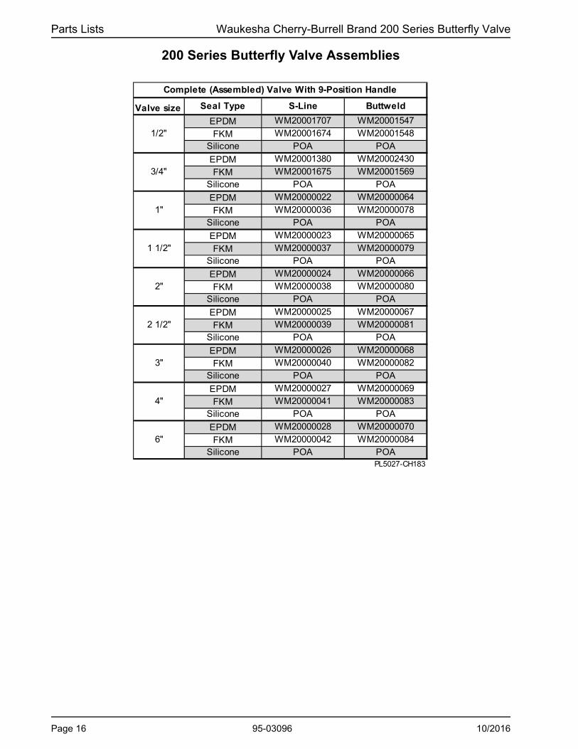
Valve size Seal Type S-Line Buttweld
EPDM WM20001707 WM20001547
FKM WM20001674 WM20001548Silicone POA POA
EPDM WM20001380 WM20002430
FKM WM20001675 WM20001569Silicone POA POA
EPDM WM20000022 WM20000064
FKM WM20000036 WM20000078Silicone POA POA
EPDM WM20000023 WM20000065
FKM WM20000037 WM20000079Silicone POA POA
EPDM WM20000024 WM20000066
FKM WM20000038 WM20000080Silicone POA POA
EPDM WM20000025 WM20000067
FKM WM20000039 WM20000081Silicone POA POA
EPDM WM20000026 WM20000068
FKM WM20000040 WM20000082Silicone POA POA
EPDM WM20000027 WM20000069
FKM WM20000041 WM20000083Silicone POA POA
EPDM WM20000028 WM20000070
FKM WM20000042 WM20000084Silicone POA POA
PL5027-CH183
1 1/2"
2"
2 1/2"
3"
6"
Complete (Assembled) Valve With 9-Position Handle
4"
1/2"
3/4"
1"
200 Series Butterfly Valve Assemblies
Page 16 95-03096 10/2016

Waukesha Cherry-Burrell Brand 200 Series Butterfly Valve Parts Lists
Item # Part Description 1/2" 3/4" 1" thru 2 1/2" 3" 4" 6"
1Intermediate Step (9-position) Handle
3029870+ 3029871+ 3029881+
2 Pull-Style Handle 3029861+ 3029862+ N/A
3Padlock Bracket for Pull-Style Handle (note 1)
N/A N/A N/A
4Pull-Style Handle with Bracket (for Prox. Switch(es) (note 2))
N/A N/A 3029876+ 3029875+ N/A N/A
Notes: PL5027-CH167
1.
2. Proximity switches are not included with the handle.
Padlock bracket is not included with the handle. Pull-Style Handle (item 2) and Padlock Bracket (item 3) must be ordered separately (Padlock not included). Field modification is required to weld the bracket to the valve body.
3029869+
3029860+
3029864+
Manual Handles
1. Intermediate Step (9-Position) Handle
2. Pull-Style Handle 3. Padlock Travel Stop Bracket for use with Pull-Style Handle (item 4) (See note 1)
4. Pull-Style Handle with bracket for Proximity Switch(es) (See note 2)
VA100-742 VA100-738 VA100-740a
3
VA100-743 VA100-744
10/2016 95-03096 Page 17

Parts Lists Waukesha Cherry-Burrell Brand 200 Series Butterfly Valve
Linear Actuator
VA100-770
10
11
6
9
94
1
8
2
3
9
5
8
12
9
7
4
6
1
3
10
VA100-769
5
As assembled, with proximity switch
Page 18 95-03096 10/2016

Waukesha Cherry-Burrell Brand 200 Series Butterfly Valve Parts Lists
1/2", 3/4", 1" 1 1/2" 2" 2 1/2" 3" 4" 6"* 1 Yoke/Bracket 1 H328289 H328290 H325093 H328291 H328574 H328575 H328576* 2 Adapter/Coupling 1 H328950 H329224* 3 Indicator 1 H329221 H329222
4Valve Bolts(see notes 2 and 3)
230-637 (M10 x 40 mm)
5Valve Nuts (see notes 2 and 3)
436-137 (M10)
* 6 Valve Bolts 2H78790
(M8 x 40 mm)
30-638 (M10 x 50 mm)
7 Manual Valve 1
* 8 Feedback Cam with pins 1 132119+ 132120+
* 9 Washers 4 POA
* 10 Actuator Bolts 2
Actuator (Air/Air) with control unit, polished
Actuator (Air/Spring) with control unit, polished
Actuator (Air/Air) without control unit, polished
Actuator (Air/Spring) without control unit, polished
12Proximity Switch, M12 threaded
1
1/2", 3/4", 1" 1 1/2" 2" 2 1/2" 3" 4" 6"
H328292 H328293 H327174 H328294 H328577 H328578 H328579
Notes: PL5027-CH184
* Included in Yoke/Bracket Kit1. See "200 Series Butterfly Valve Assemblies" page.2. Re-used from Manual valve assembly.3. 6" valve (not shown) has quantity 4 valve bolts (item 4) and quantity 6 Valve nuts (item 5).
Qty
Yoke/Bracket Kit (contains items above marked with *)
Part DescriptionItem #
Valve Size
36-136 (M8)
17-73
H327176
30-635 (M8 x 30 mm)
H79594
H203918
Valve Size
132118+
H14634
See note 1
H328357
H78791 (M8 x 35 mm)
11
H203917
1
H78805 (M10 x 14mm)
H328358
H328353
H328361
H78770 (M8 x 12 mm)
H328355
H328360
Linear Actuator
10/2016 95-03096 Page 19

Parts Lists Waukesha Cherry-Burrell Brand 200 Series Butterfly Valve
Notes
Page 20 95-03096 10/2016


200 Series Butterfly ValveMANUAL AND PNEUMATIC ACTUATORS
SPX FLOW
611 Sugar Creek Road
Delavan, WI 53115
P: (262) 728-1900 or (800) 252-5200
F: (262) 728-4904 or (800) 252-5012
SPX FLOW, Inc. reserves the right to incorporate our latest design and material
changes without notice or obligation.
Design features, materials of construction and dimensional data, as described in
this bulletin, are provided for your information only and should not be relied upon
unless confirmed in writing.
Please contact your local sales representative for product availability in your
region. For more information visit www.spxflow.com.
The green “>” is a trademark of SPX FLOW, Inc.
ISSUED: 10/2016
COPYRIGHT © 2016 SPX FLOW, Inc.