Embed Size (px)
Citation preview
HVAC PRODUC SHVAC PRODUC S HVAC PRODUC S
200 & IDB SERIESINLINE DUCT BLOWERSOPERATION INSTRUCTIONS AND PARTS MANUAL
200 SERIES MODELS: 207, 209, 210, 212, 215, 218IDB SERIES MODELS: IDB07, IDB09, IDB10, IDB12, IDB15, IDB18
GENERAL SAFETYRotating parts, (pulleys, shafts and belts) on fans should not be exposed. Where these components are not protected by ductwork, cabinetsor covers, appropriate guards should be employed to restrict exposure to rotating parts. Access doors should not be opened with the fanoperating to avoid foreign objects being drawn into the system. On initial start-up, a careful inspection should be carried out to ensure noforeign material is present which could become airborne in the system.Read installation and operation instructions carefully before attempting to install, operate or service Canarm/Delhi 200 Series orCanarm/Delhi IDB Series Blowers. Failure to comply with instructions could result in personal injury and/or property damage. Retaininstructions for future reference.
BEFORE YOU BEGINInspect unit for damage, report any shipping damage to carrier. Check all fasteners, re-tighten as required. Rotate the blower wheel byhand to ensure free rotation. If rubbing occurs, loosen the set screw(s), re-position the wheel to the shaft center, re-tighten set screws.
INSTALLATION
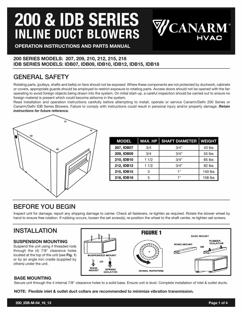
SUSPENSION MOUNTINGSuspend the unit using 4 threaded rodsthrough the (4) 7/8" clearance holeslocated at the top of the unit (see Fig. 1)or by an angle iron cradle (supplied byothers) under the unit.
MODEL MAX. HP SHAFT DIAMETER WEIGHT207, IDB07 3/4 3/4" 43 lbs209, IDB09 3/4 3/4" 55 lbs210, IDB10 1 1/2 3/4" 65 lbs212, IDB12 1 1/2 3/4" 82 lbs215, IDB15 3 1" 140 lbs218, IDB18 5 1" 158 lbs
FIGURE 1
BASE MOUNTINGSecure unit through the 4 internal 7/8" clearance holes to a solid base. Ensure unit is level. Complete installation of inlet & outlet ducts.
NOTE: Flexible inlet & outlet duct collars are recommended to minimize vibration transmission.
200_IDB-M-04_16_13 Page 1 of 4
HVAC PRODUC SHVAC PRODUC S HVAC PRODUC S
200 & IDB SERIESINLINE DUCT BLOWERS
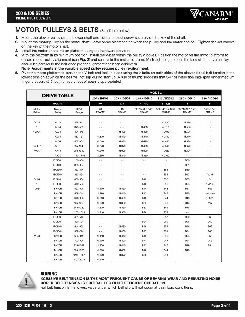
MOTOR, PULLEYS & BELTS (See Table below)
1. Mount the blower pulley on the blower shaft and tighten the set screw securely on the key of the shaft.2. Mount the motor pulley on the motor shaft. Leave some clearance between the pulley and the motor end bell. Tighten the set screws
on the key of the motor shaft.3. Install the motor on the motor platform using the hardware provided.4. With the platform in its minimum position, install the V-belt within the pulley grooves. Position the motor on the motor platform to
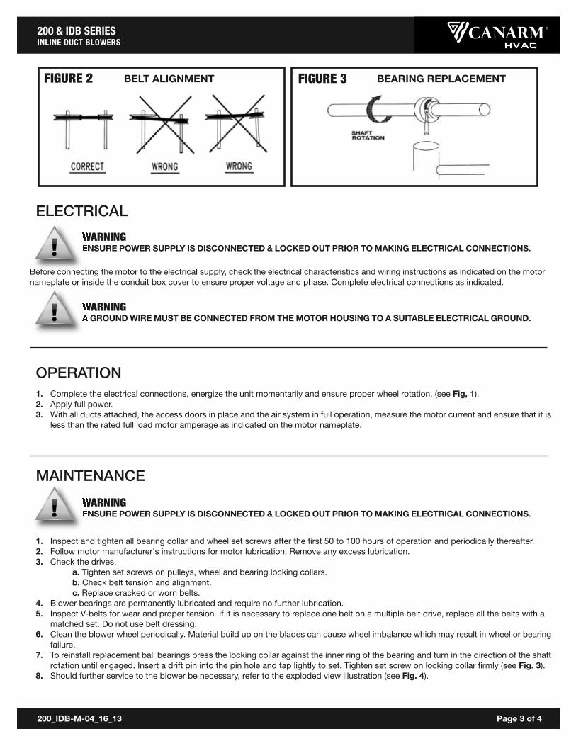
ensure proper pulley alignment (see Fig. 2) and secure to the motor platform. (A straight edge across the face of the driven pulleyshould be parallel to the belt once proper alignment has been achieved). Note: Adjustments in the variable speed pulley require pulley re-alignment.
5. Pivot the motor platform to tension the V-belt and lock in place using the 2 bolts on both sides of the blower. (Ideal belt tension is thelowest tension at which the belt will not slip during start up. A rule of thumb suggests that 3/4" of deflection mid-span under mediumfinger pressure (2-3 lbs.) for every foot of span is appropriate.)
WARNINGEXCESSIVE BELT TENSION IS THE MOST FREQUENT CAUSE OF BEARING WEAR AND RESULTING NOISE.PROPER BELT TENSION IS CRITICAL FOR QUIET EFFICIENT OPERATION.Ideal belt tension is the lowest value under which belt slip will not occur at peak load conditions.
207 / IDB07 209 / IDB09 210 / IDB10 212 / IDB12 215 / IDB15 218 / IDB18
3/4 3/4 1 - 1/2 1 - 1/2 3 5
Motor Pulley
Blower Pulley
RPM Range
48 FRAME
48 FRAME
56T/143T & 145T FRAME
56T/143T & 145T FRAME
56T/143T & 145T FRAME
182T/184TFRAME
- - - - - - - - - - - - - -
IVL34 AL104 335-511 - - - - - - - - 4L530 4L570 - -
& AL94 373-569 - - - - - 4L480 4L510 4L550 - -
1VP34 AL84 421-642 - - 4L430 4L460 4L490 4L530 - -
AL74 483-737 4L370 4L410 4L440 4L480 4L510 - -
AL64 567-865 4L360 4L390 4L420 4L450 4L490 - -
3/4 HP AL51 685-1046 4L340 4L370 4L400 4L440 4L470 - -
MAX. AK41 862-1316 4L310 4L360 4L390 4L420 4L450 - -
AK30 1170-1786 4L290 4L340 4L360 4L400 - - - -
BK160H 168-333 - - - - - - - - B66
BK140H 308-384 - - - - - - - - B61
BK130H 333-416 - - - - - - B56 B59
BK120H 363-454 - - - - - - B54 B57 IVL34
IVL34 BK110H 398-500 - - - - B48 B52 B55 &
& BK100H 440-555 - - - - B46 B50 B53 1VP34
1VP34 BK90H 492-625 4L400 4L430 B44 B48 B51 not
BK80H 559-714 4L380 4L410 B42 B46 B50 available
BK70H 646-833 4L360 4L400 B40 B44 B48 1-1/8"
BK60H 766-1000 4L340 4L380 B39 B43 B46 bore
BK50H 940-1230 4L320 4L360 B37 B41 B45
BK40H 1150-1553 4L310 4L350 B36 B39 - -
BK130H 431-546 - - - - - - B57 B60 B65
BK120H 469-595 - - - - B51 B55 B58 B63
BK110H 514-655 - - 4L480 B49 B53 B56 B62
BK100H 568-728 - - 4L460 B47 B51 B54 B60
IVP44 BK90H 636-819 4L410 4L440 B45 B49 B53 B58
BK80H 722-936 4L390 4L430 B44 B47 B51 B56
BK70H 835-1092 4L370 4L410 B42 B46 B49 B54
BK60H 990-1309 4L350 4L390 B40 B44 B48 - -
BK50H 1215-1607 4L330 4L370 B38 B41 - - - -
BK40H 1509-2048 4L310 - - - - - - - - - -
MODELDRIVE TABLE
MAX HP
200_IDB-M-04_16_13 Page 2 of 4
ELECTRICAL
1. Complete the electrical connections, energize the unit momentarily and ensure proper wheel rotation. (see Fig, 1).2. Apply full power.3. With all ducts attached, the access doors in place and the air system in full operation, measure the motor current and ensure that it is
less than the rated full load motor amperage as indicated on the motor nameplate.
BELT ALIGNMENTFIGURE 2 FIGURE 3
HVAC PRODUC SHVAC PRODUC S HVAC PRODUC S
200 & IDB SERIESINLINE DUCT BLOWERS
200_IDB-M-04_16_13 Page 3 of 4
WARNINGENSURE POWER SUPPLY IS DISCONNECTED & LOCKED OUT PRIOR TO MAKING ELECTRICAL CONNECTIONS.
WARNINGA GROUND WIRE MUST BE CONNECTED FROM THE MOTOR HOUSING TO A SUITABLE ELECTRICAL GROUND.
WARNINGENSURE POWER SUPPLY IS DISCONNECTED & LOCKED OUT PRIOR TO MAKING ELECTRICAL CONNECTIONS.
BEARING REPLACEMENT
Before connecting the motor to the electrical supply, check the electrical characteristics and wiring instructions as indicated on the motornameplate or inside the conduit box cover to ensure proper voltage and phase. Complete electrical connections as indicated.
OPERATION
1. Inspect and tighten all bearing collar and wheel set screws after the first 50 to 100 hours of operation and periodically thereafter.2. Follow motor manufacturer's instructions for motor lubrication. Remove any excess lubrication.3. Check the drives.
a. Tighten set screws on pulleys, wheel and bearing locking collars.b. Check belt tension and alignment.c. Replace cracked or worn belts.
4. Blower bearings are permanently lubricated and require no further lubrication.5. Inspect V-belts for wear and proper tension. If it is necessary to replace one belt on a multiple belt drive, replace all the belts with a
matched set. Do not use belt dressing.6. Clean the blower wheel periodically. Material build up on the blades can cause wheel imbalance which may result in wheel or bearing
failure.7. To reinstall replacement ball bearings press the locking collar against the inner ring of the bearing and turn in the direction of the shaft
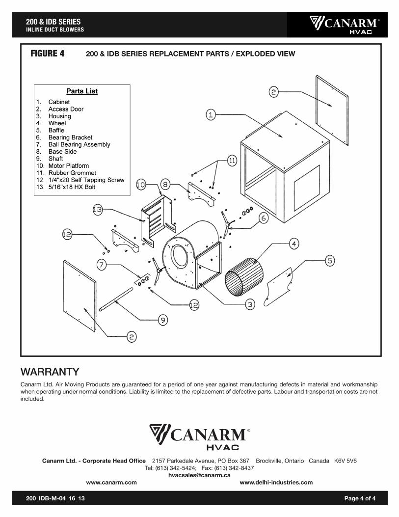
rotation until engaged. Insert a drift pin into the pin hole and tap lightly to set. Tighten set screw on locking collar firmly (see Fig. 3).8. Should further service to the blower be necessary, refer to the exploded view illustration (see Fig. 4).
MAINTENANCE
HVAC PRODUC SHVAC PRODUC S HVAC PRODUC S
200 & IDB SERIESINLINE DUCT BLOWERS
200_IDB-M-04_16_13 Page 4 of 4
200 & IDB SERIES REPLACEMENT PARTS / EXPLODED VIEWFIGURE 4
WARRANTYCanarm Ltd. Air Moving Products are guaranteed for a period of one year against manufacturing defects in material and workmanshipwhen operating under normal conditions. Liability is limited to the replacement of defective parts. Labour and transportation costs are notincluded.
Canarm Ltd. - Corporate Head Office 2157 Parkedale Avenue, PO Box 367 Brockville, Ontario Canada K6V 5V6Tel: (613) 342-5424; Fax: (613) 342-8437
[email protected] www.delhi-industries.com
HVAC PRODUC SHVAC PRODUC S HVAC PRODUC S


![Presentation idb[1]](https://img.pdfslide.us/doc/110x75/5477df3db4af9f54028b48b8/presentation-idb1.jpg)