Embed Size (px)
Citation preview
© 2016 Electric Power Research Institute, Inc. All rights reserved.
Carl LatiolaisSenior Program Manager NDE Reliability
6th International CANDU ISI Workshop/NDT in Canada 2016 Conference
November 2016
20 Years of Performance Demonstration Activities in
the United States“Where we have been and where we are going”
NDT in Canada 2016 & 6th International CANDU In-Service Inspection Workshop, Nov 15-17, 2016, Burlington, ON (Canada)
www.ndt.net/app.NDTCanada2016
2© 2016 Electric Power Research Institute, Inc. All rights reserved.
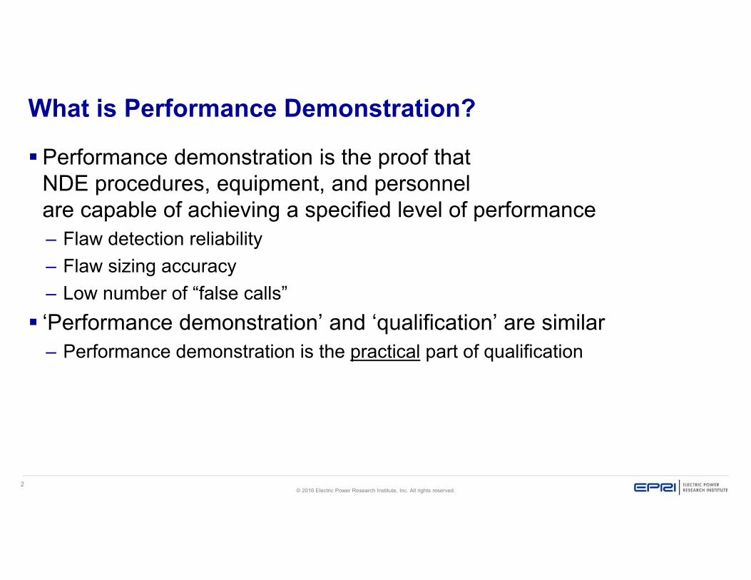
What is Performance Demonstration?
Performance demonstration is the proof that NDE procedures, equipment, and personnelare capable of achieving a specified level of performance– Flaw detection reliability– Flaw sizing accuracy– Low number of “false calls”
‘Performance demonstration’ and ‘qualification’ are similar– Performance demonstration is the practical part of qualification

3© 2016 Electric Power Research Institute, Inc. All rights reserved.
Worldwide Demand for Performance Demonstration The demand for rigorous performance
demonstration is increasing– New regulations and requirements– Long term operation– Expansion of the nuclear fleet– Increasing need for statistical measures of NDE
reliability Impact of the demand
– Utilities and NDE vendors are scheduling well in advance
– Mockup manufacturers are operating at full capacity
Expect this trend to continue
4© 2016 Electric Power Research Institute, Inc. All rights reserved.
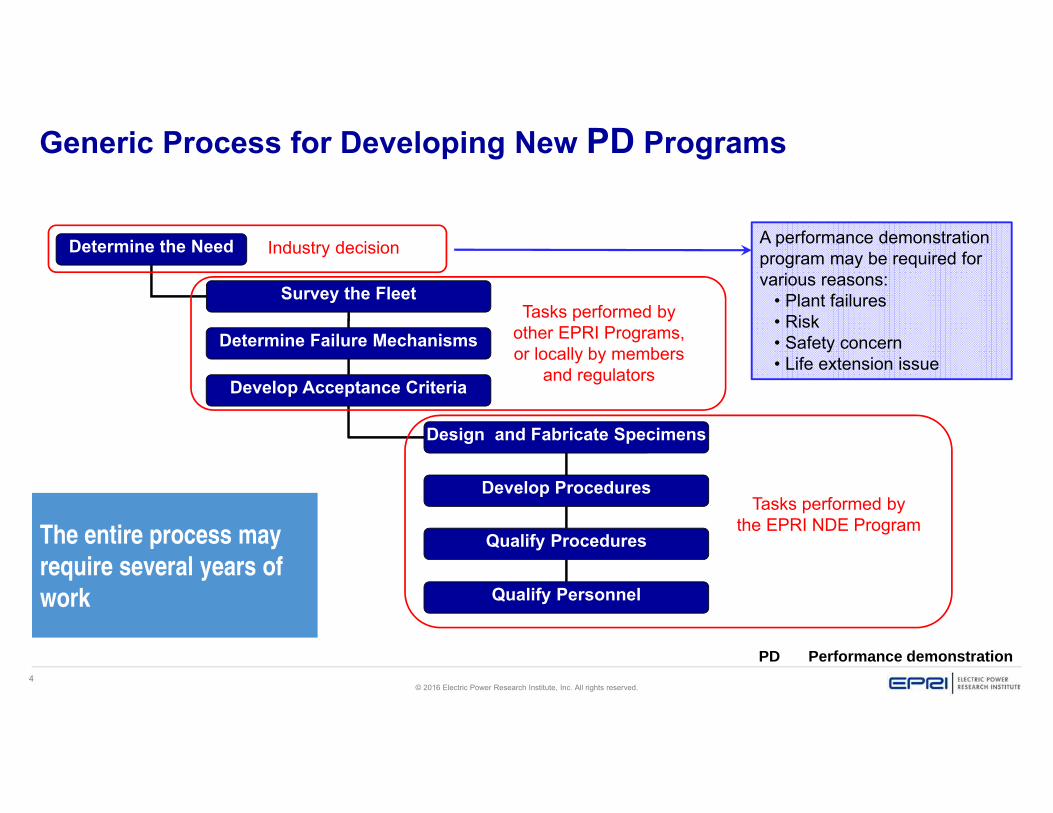
Generic Process for Developing New PD Programs
Determine the Need
Determine Failure Mechanisms
Develop Acceptance Criteria
Survey the Fleet
Design and Fabricate Specimens
Develop Procedures
Qualify Procedures
Qualify Personnel
Tasks performed by other EPRI Programs, or locally by members
and regulators
Tasks performed bythe EPRI NDE Program
A performance demonstration program may be required for various reasons:
• Plant failures• Risk• Safety concern• Life extension issue
Industry decision
The entire process may
require several years of
work
PD Performance demonstration
5© 2016 Electric Power Research Institute, Inc. All rights reserved.
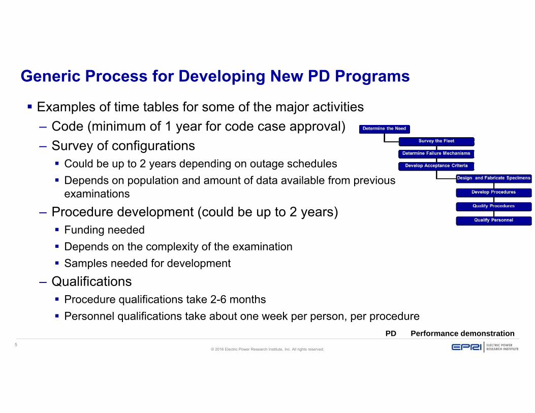
Generic Process for Developing New PD Programs
Examples of time tables for some of the major activities– Code (minimum of 1 year for code case approval)– Survey of configurations
Could be up to 2 years depending on outage schedules Depends on population and amount of data available from previous
examinations– Procedure development (could be up to 2 years)
Funding needed Depends on the complexity of the examination Samples needed for development
– Qualifications Procedure qualifications take 2-6 months Personnel qualifications take about one week per person, per procedure
PD Performance demonstration

6© 2016 Electric Power Research Institute, Inc. All rights reserved.
Types of Performance Demonstration
Each country’s requirements are different, but always it is some combination of two primary approaches:
Practicaldemonstration(physical trials)
Technicaljustification
(theoretical argument)
USA:ASME Code
Europe:ENIQEPRI NDE Program is the
original provider of performance demonstration services for compliance with ASME Code requirements for most of the primary pressure boundary
EPRI NDE Program has helped utilities in many nations, with both ASME and non-ASME requirements:- Developing new performance demonstration programs,
processes and organizations
- Providing justifications for applying EPRI’s PD methods in the local regulatory environment
ASME American Society of Mechanical Engineers ENIQ European Network for Inspection QualificationPD Performance demonstration

7© 2016 Electric Power Research Institute, Inc. All rights reserved.
Scope of the EPRI NDE Performance Demonstration Team Qualifications of ultrasonic procedures,
equipment and personnel – ASME Section XI, Appendix VIII– RPV upper head penetrations– International qualification support– Any future formal qualification – Mockup design and fabrication
coordination for entire EPRI NDE group
Strategic AlliancesCRIEPI
(Japan Qualification Body)
KHNP Research(Korea Qualification Body)
SQC(Sweden Qualification Body)
QST(Switzerland Qualification Body)
ASME American Society of Mechanical Engineers
ENIQ European Network for Inspection Qualification
PD Performance demonstration
8© 2016 Electric Power Research Institute, Inc. All rights reserved.
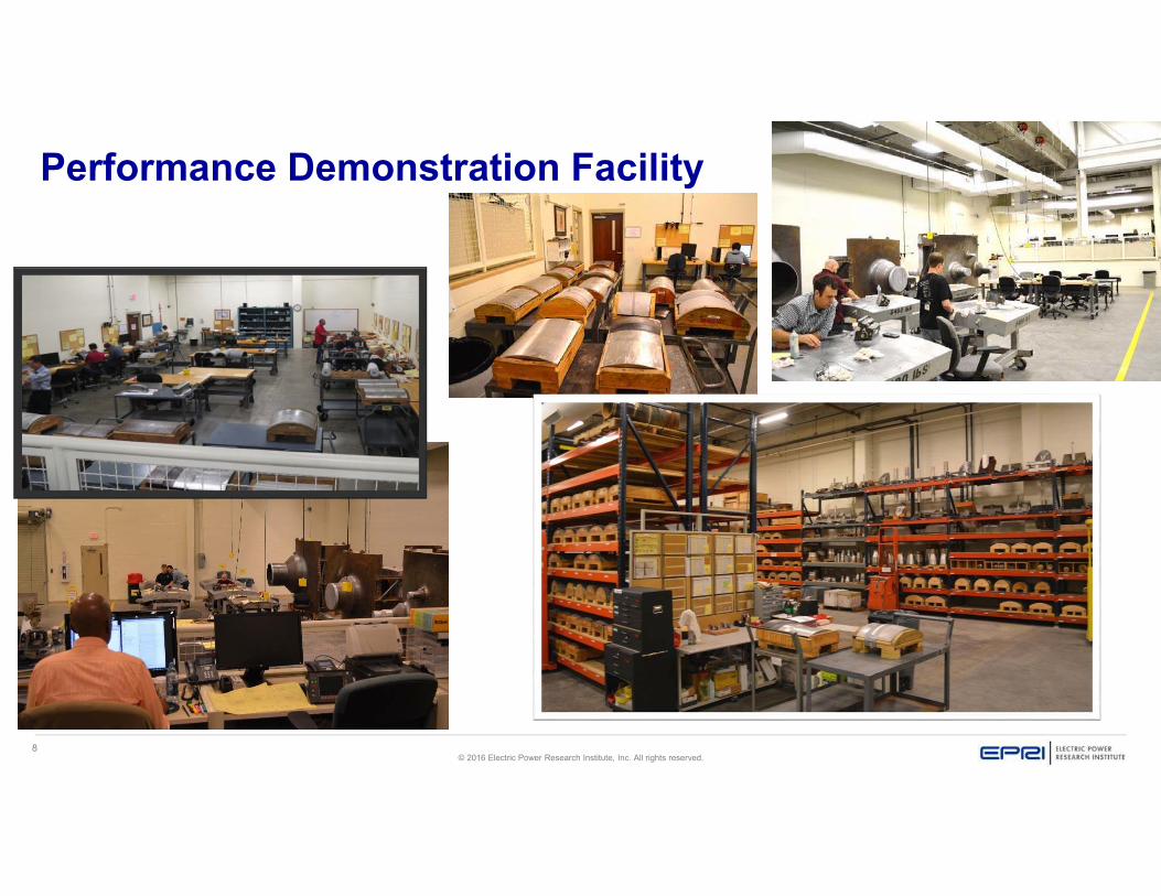
Performance Demonstration Facility
9© 2016 Electric Power Research Institute, Inc. All rights reserved.
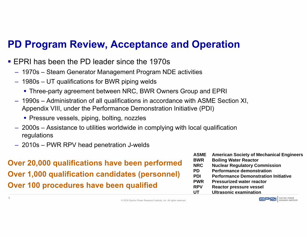
PD Program Review, Acceptance and Operation EPRI has been the PD leader since the 1970s
– 1970s – Steam Generator Management Program NDE activities– 1980s – UT qualifications for BWR piping welds
Three-party agreement between NRC, BWR Owners Group and EPRI– 1990s – Administration of all qualifications in accordance with ASME Section XI,
Appendix VIII, under the Performance Demonstration Initiative (PDI) Pressure vessels, piping, bolting, nozzles
– 2000s – Assistance to utilities worldwide in complying with local qualification regulations
– 2010s – PWR RPV head penetration J-welds
Over 20,000 qualifications have been performedOver 1,000 qualification candidates (personnel)Over 100 procedures have been qualified
ASME American Society of Mechanical EngineersBWR Boiling Water Reactor NRC Nuclear Regulatory CommissionPD Performance demonstrationPDI Performance Demonstration InitiativePWR Pressurized water reactorRPV Reactor pressure vesselUT Ultrasonic examination

10© 2016 Electric Power Research Institute, Inc. All rights reserved.
ASME Code Section XI, Appendix VIIIDefines Separate Demonstrations for:
Piping Supplements– 2, Wrought austenitic piping welds– 3, Wrought ferritic piping welds– 9, Cast austenitic piping– 10, Bimetallic piping welds– 11, Overlaid wrought austenitic piping
welds
• Reactor Vessel Supplements– 4, Clad/base metal interface of reactor vessel– 5, Nozzle examination from the outside
surface– 6, Reactor vessel welds other than clad/base
metal interface – 7, Nozzle examination from the inside surface
• Other– 8, Bolts and studs
And within each qualification there are:- Procedure, personnel, and equipment qualifications
- Flaw detection, flaw length sizing, and flaw depth sizing qualificationsASME American Society of Mechanical Engineers
11© 2016 Electric Power Research Institute, Inc. All rights reserved.
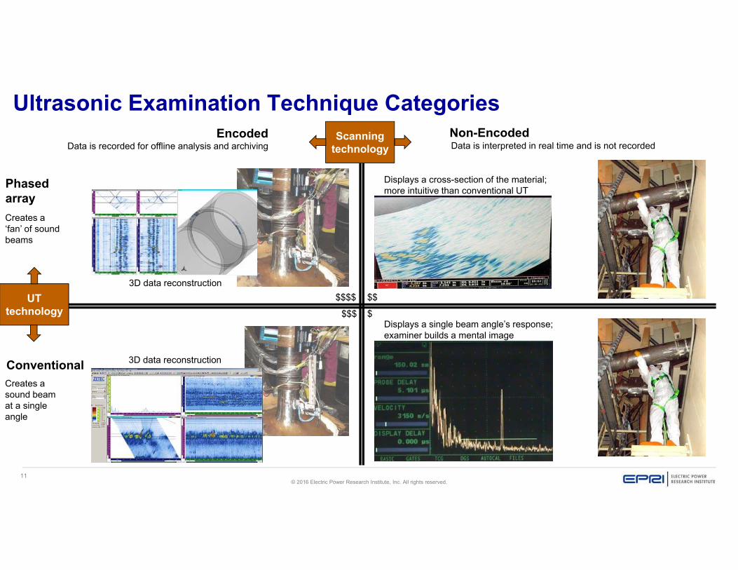
Ultrasonic Examination Technique CategoriesEncoded Non-Encoded
Phasedarray
Conventional
Data is recorded for offline analysis and archiving Data is interpreted in real time and is not recorded
Creates a ‘fan’ of sound beams
Creates a sound beam at a single angle
Displays a cross-section of the material; more intuitive than conventional UT
Displays a single beam angle’s response; examiner builds a mental image
3D data reconstruction$$$$
$$$ $
$$UTtechnology
Scanningtechnology
3D data reconstruction
12© 2016 Electric Power Research Institute, Inc. All rights reserved.
ASME Code Section XI, Appendix VIII
Qualified Non-encoded UT Procedures
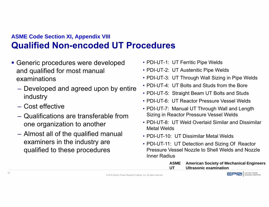
Generic procedures were developed and qualified for most manual examinations – Developed and agreed upon by entire
industry– Cost effective– Qualifications are transferable from
one organization to another– Almost all of the qualified manual
examiners in the industry are qualified to these procedures
• PDI-UT-1: UT Ferritic Pipe Welds • PDI-UT-2: UT Austenitic Pipe Welds • PDI-UT-3: UT Through Wall Sizing in Pipe Welds • PDI-UT-4: UT Bolts and Studs from the Bore• PDI-UT-5: Straight Beam UT Bolts and Studs• PDI-UT-6: UT Reactor Pressure Vessel Welds • PDI-UT-7: Manual UT Through Wall and Length
Sizing in Reactor Pressure Vessel Welds• PDI-UT-8: UT Weld Overlaid Similar and Dissimilar
Metal Welds• PDI-UT-10: UT Dissimilar Metal Welds • PDI-UT-11: UT Detection and Sizing Of Reactor
Pressure Vessel Nozzle to Shell Welds and Nozzle Inner Radius
ASME American Society of Mechanical EngineersUT Ultrasonic examination
13© 2016 Electric Power Research Institute, Inc. All rights reserved.
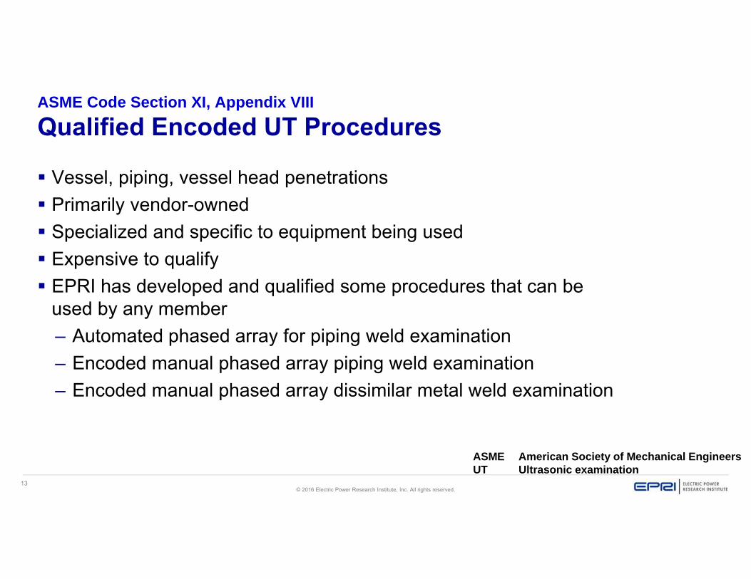
ASME Code Section XI, Appendix VIII
Qualified Encoded UT Procedures
Vessel, piping, vessel head penetrations Primarily vendor-owned Specialized and specific to equipment being used Expensive to qualify EPRI has developed and qualified some procedures that can be
used by any member– Automated phased array for piping weld examination– Encoded manual phased array piping weld examination– Encoded manual phased array dissimilar metal weld examination
ASME American Society of Mechanical EngineersUT Ultrasonic examination
14© 2016 Electric Power Research Institute, Inc. All rights reserved.
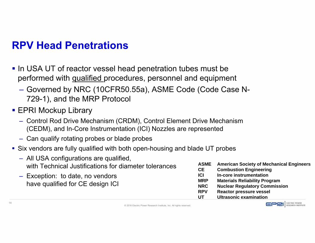
RPV Head Penetrations
In USA UT of reactor vessel head penetration tubes must be performed with qualified procedures, personnel and equipment– Governed by NRC (10CFR50.55a), ASME Code (Code Case N-
729-1), and the MRP Protocol EPRI Mockup Library
– Control Rod Drive Mechanism (CRDM), Control Element Drive Mechanism (CEDM), and In-Core Instrumentation (ICI) Nozzles are represented
– Can qualify rotating probes or blade probes Six vendors are fully qualified with both open-housing and blade UT probes
– All USA configurations are qualified, with Technical Justifications for diameter tolerances
– Exception: to date, no vendors have qualified for CE design ICI
ASME American Society of Mechanical Engineers CE Combustion EngineeringICI In-core instrumentation MRP Materials Reliability ProgramNRC Nuclear Regulatory CommissionRPV Reactor pressure vesselUT Ultrasonic examination

15© 2016 Electric Power Research Institute, Inc. All rights reserved.
New Development: Virtual Mockups
Physical mockups are very expensive
Virtual mockups will be less expensive– Add or delete flaws: “cut and
paste”– Change flaw size or location– Insert simulated data
This approach can generate an unlimited number of practice samples at a lower cost
In the example above, one data file is real, the other is virtual.
Which one is real?

16© 2016 Electric Power Research Institute, Inc. All rights reserved.
Virtual NDE Ultrasonic Data Players A windows-based software that allows users
to simulate conditions of manual ultrasonic examinations by providing practice opportunities without requiring access to physical ultrasonic instruments or pipe specimens
17© 2016 Electric Power Research Institute, Inc. All rights reserved.
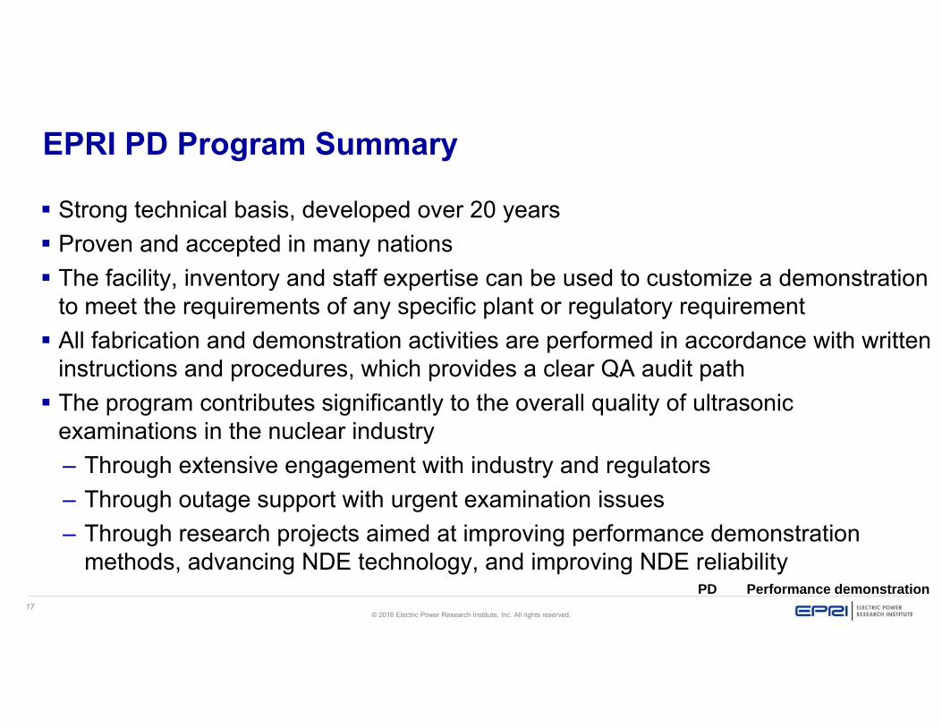
EPRI PD Program Summary
Strong technical basis, developed over 20 years Proven and accepted in many nations The facility, inventory and staff expertise can be used to customize a demonstration
to meet the requirements of any specific plant or regulatory requirement All fabrication and demonstration activities are performed in accordance with written
instructions and procedures, which provides a clear QA audit path The program contributes significantly to the overall quality of ultrasonic
examinations in the nuclear industry– Through extensive engagement with industry and regulators– Through outage support with urgent examination issues– Through research projects aimed at improving performance demonstration
methods, advancing NDE technology, and improving NDE reliabilityPD Performance demonstration

18© 2016 Electric Power Research Institute, Inc. All rights reserved.
Together…Shaping the Future of Electricity