Embed Size (px)
Citation preview
R5 063551/06 2
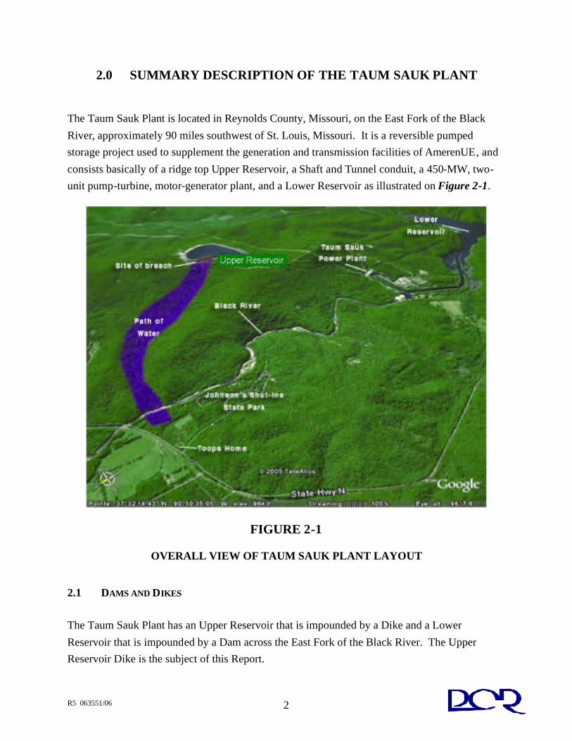
2.0 SUMMARY DESCRIPTION OF THE TAUM SAUK PLANT
The Taum Sauk Plant is located in Reynolds County, Missouri, on the East Fork of the Black River, approximately 90 miles southwest of St. Louis, Missouri. It is a reversible pumped storage project used to supplement the generation and transmission facilities of AmerenUE, and consists basically of a ridge top Upper Reservoir, a Shaft and Tunnel conduit, a 450-MW, two-unit pump-turbine, motor-generator plant, and a Lower Reservoir as illustrated on Figure 2-1.
FIGURE 2-1
OVERALL VIEW OF TAUM SAUK PLANT LAYOUT
2.1 DAMS AND DIKES The Taum Sauk Plant has an Upper Reservoir that is impounded by a Dike and a Lower Reservoir that is impounded by a Dam across the East Fork of the Black River. The Upper Reservoir Dike is the subject of this Report.
R5 063551/06 3
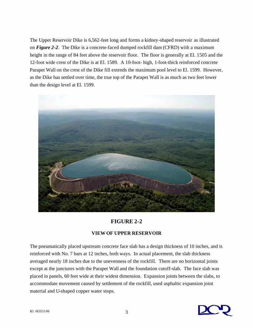
The Upper Reservoir Dike is 6,562-feet long and forms a kidney-shaped reservoir as illustrated on Figure 2-2. The Dike is a concrete-faced dumped rockfill dam (CFRD) with a maximum height in the range of 84 feet above the reservoir floor. The floor is generally at El. 1505 and the 12-foot wide crest of the Dike is at El. 1589. A 10-foot- high, 1-foot-thick reinforced concrete Parapet Wall on the crest of the Dike fill extends the maximum pool level to El. 1599. However, as the Dike has settled over time, the true top of the Parapet Wall is as much as two feet lower than the design level at El. 1599.
FIGURE 2-2
VIEW OF UPPER RESERVOIR
The pneumatically placed upstream concrete face slab has a design thickness of 10 inches, and is reinforced with No. 7 bars at 12 inches, both ways. In actual placement, the slab thickness averaged nearly 18 inches due to the unevenness of the rockfill. There are no horizontal joints except at the junctures with the Parapet Wall and the foundation cutoff-slab. The face slab was placed in panels, 60 feet wide at their widest dimension. Expansion joints between the slabs, to accommodate movement caused by settlement of the rockfill, used asphaltic expansion joint material and U-shaped copper water stops.
R5 063551/06 4
As depicted on the design drawings, a reinforced concrete plinth was provided at the toe of the concrete face. Where the natural rock surface was substantially higher than the reservoir floor, the rock was excavated on a near vertical slope and the plinth was placed at the top of the excavated rock. In these areas, the rock cut between the reservoir floor and the plinth was sealed with a 4-inch layer of wire mesh-reinforced shotcrete. The entire reservoir bottom was sealed with two 2-inch layers of hot-mix asphaltic concrete placed over leveled and compacted quarry muck. Around the edge of the asphaltic concrete, a single line grout curtain was constructed to limit seepage under the Dike. An Access Tunnel through the northern side of the Dike provides access to the Reservoir floor. The Access Tunnel is concrete lined, 19 feet in diameter, and horseshoe shaped. The upstream face is fitted with a hinged steel bulkhead gate that opens into the Upper Reservoir. The gate is 10.4-foot wide by 12.4-foot high and is hinged at the bottom. The gate is vertical when closed and horizontal when open. The Upper Reservoir was constructed without a spillway. RIZZO presumes that this is because it has no drainage area and the only incoming flow is by pumping and direct rainfall. A system of redundant water level instruments was designed to prevent overtopping of the Dike by pumping. These instruments are addressed later in this Report. 2.2 LOWER RESERVOIR DAM As shown on Figure 2-3, the Lower Reservoir Dam is located in a narrow steep-sided gorge just
downstream of the junction of Taum Sauk Creek and the East Fork of the Black River. It forms the Lower Reservoir with a surface area of 395 acres and a water level at the spillway crest. The
canyon at this location is in exposed hard blocky rhyolite rock of good quality. The Lower Reservoir design volume at the spillway crest is 6,350 acre-feet.
R5 063551/06 5
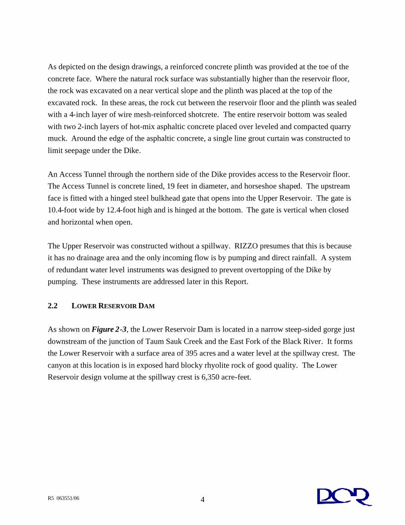
FIGURE 2-3
VIEW OF LOWER RESERVOIR DAM The Lower Reservoir Dam is a concrete gravity dam founded on rock with a maximum height of 60 feet above bedrock. The entire 390-foot long Lower Reservoir Dam is an ungated overflow spillway except for two piers that support the operating deck. The spillway crest is at El. 750 and the operating deck is at El. 765. The Dam section has a base width at the maximum section equal to 1.25 times the height and a downstream slope equal to 0.83 Horizontal to 1 Vertical. The spillway discharges to a reinforced concrete flip bucket with a 28-foot radius. The elevations of the flip-buckets for the abutment blocks are higher than those for the center blocks as may be seen on Figure 2-3. A single-line grout curtain is located along the upstream side of the gallery. The grout holes are spaced 6 feet apart and extend 20 feet below the base of the Dam. Foundation drainage consists of a longitudinal "box" drain formed with one-half of a 12-inch pipe. A longitudinal foundation drain in the bedrock, below the downstream side of the gallery, connects to transverse formed

R5 063551/06 6
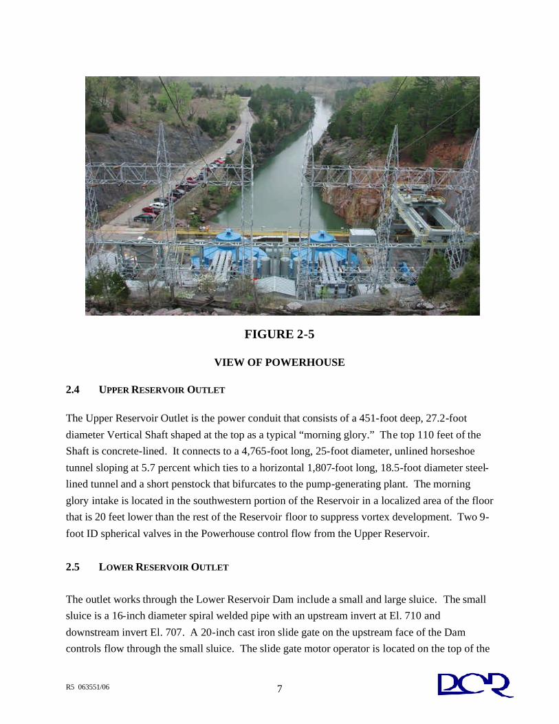
"box" drains at each block joint that discharge to the downstream face of the Dam. In addition, at each block joint, a formed drain extends from the foundation drain to the gallery floor. Piezometers, installed in eight blocks, consist of copper tubing extending vertically down from the middle of the gallery, then horizontally within the bottom lift of concrete to a point 10 feet downstream of the downstream gallery wall. The tubing is terminated in an excavated depression in the foundation rock that is filled with gravel. 2.3 POWERHOUSE The Taum Sauk Plant Powerhouse is located at the upstream end of the Lower Reservoir about two-miles from the Upper Reservoir as illustrated on Figure 2-4. It is situated in a deep, narrow canyon through which a tailrace channel was excavated to connect to the East Fork of the Black River as shown on Figure 2-5. The Powerhouse is connected to the Upper Reservoir via a concrete and steel-lined Shaft and tunnel (not to be confused with the Access Tunnel mentioned previously). The initial reversible pump-turbine rating for each unit was 175 MW, but these have been upgraded such that the total plant capacity is now in the range of 450 MW. The tailrace that leads to the Lower Reservoir is about 65-feet wide and 2,000-feet long.
FIGURE 2-4
VIEW OF POWERHOUSE IN RELATION TO UPPER RESERVOIR
R5 063551/06 7
FIGURE 2-5
VIEW OF POWERHOUSE
2.4 UPPER RESERVOIR OUTLET The Upper Reservoir Outlet is the power conduit that consists of a 451-foot deep, 27.2-foot diameter Vertical Shaft shaped at the top as a typical “morning glory.” The top 110 feet of the Shaft is concrete-lined. It connects to a 4,765-foot long, 25-foot diameter, unlined horseshoe
tunnel sloping at 5.7 percent which ties to a horizontal 1,807-foot long, 18.5-foot diameter steel-lined tunnel and a short penstock that bifurcates to the pump-generating plant. The morning glory intake is located in the southwestern portion of the Reservoir in a localized area of the floor that is 20 feet lower than the rest of the Reservoir floor to suppress vortex development. Two 9-foot ID spherical valves in the Powerhouse control flow from the Upper Reservoir.
2.5 LOWER RESERVOIR OUTLET The outlet works through the Lower Reservoir Dam include a small and large sluice. The small sluice is a 16-inch diameter spiral welded pipe with an upstream invert at El. 710 and
downstream invert El. 707. A 20-inch cast iron slide gate on the upstream face of the Dam controls flow through the small sluice. The slide gate motor operator is located on the top of the
R5 063551/06 8
4-foot wide pier on the crest of the Dam. An intake structure extends 7 feet upstream of the Dam and provides a single set of slots for either a trash rack or stop logs. The large sluice is an 8-foot wide by 10-foot high steel-lined conduit with an invert at El 705. An 8-foot by 10-foot cast iron slide gate located on the upstream face of the Dam controls flow through the sluice. The slide gate motor operator is located atop the 13-foot wide pier on the spillway crest. An intake structure upstream of the sluice provides slots for stop logs and a trash rack. 2.5.1 Standard Operational Procedures1 The Taum Sauk Plant is a peaking and emergency reserve facility. A typical daily cycle in the summer is to generate from about 2 PM until 7 PM by releasing water from the Upper Reservoir through the turbines to the Lower Reservoir and pump from the Lower Reservoir to the Upper Reservoir from 11 PM until about 6 or 7 AM. Generation and pump start as well as the respective durations are determined by system needs and controlled from AmerenUE's Osage Plant. In the winter the number of cycles is typically less, with no cycles on some days. Operation in the fall and spring typically follows ambient temperature and system load requirements. The normal maximum level for the Upper Reservoir is El. 1596. The Upper Reservoir can be drawn down to El. 1525 feet and possibly to El. 1515 if only one turbine/generator unit is operating without causing problems with the hydro machinery. The normal minimum level in the Lower Reservoir is El. 736. Although this is above the bottom of the Lower Reservoir, operation below this level draws debris up the Powerhouse tailrace channel. The debris interferes with the pumping operations and sets the practical minimum water level elevation. The normal maximum water level is El. 749.5 feet or 6 inches below the spillway crest. AmerenUE operates the gates manually such that outflow over the spillway and through the sluice gates is equal to Lower Reservoir inflow to satisfy FERC license requirements.
1 The summary of Standard Operational Procedures is based on discussions with AmerenUE personnel.
R5 063551/06 9
The project is controlled through a microwave / fiber link from Taum Sauk to St. Louis to Osage. The Osage operators operate the Taum Sauk units under the direction of the load dispatcher in St. Louis. As originally designed and constructed, the useable volume in the Lower Reservoir was greater than the volume of the Upper Reservoir. The design volume of the Lower Reservoir was reduced by the need to raise the minimum operating water level from El. 734 feet to El. 736 feet due to the debris being pulled up the tailrace channel. Although trash racks prevent the debris from being pulled into the pumps, the debris interferes with pumping operations.
2.6 ABRIDGED HISTORY OF ROCKFILL DAMS (AND DIKES) To fully appreciate the design and construction bases employed in the late 1950s and early 1960s when the Rockfill Dike for the Upper Reservoir was built, we have looked at the state of the practice on a generic basis. We provide below an abridged history of the development of rockfill dams (and dikes) up to the mid 1960s. The following text is paraphrased and or directly quoted from Section 6 in the text entitled “Development of Engineering for Dams in the United States” published by the International Committee on Large Dams (ICOLD), now named the United States Society for Dams (USSD), in 1988 as edited by Kollgaard and Chadwicke. We specifically utilize here Chapter 6 entitled “Rockfill Dams” authored by J. Barry Cooke and Arthur G. Strassburger. Incidentally, Mr. Cooke (deceased) was the primary consultant for the Upper Reservoir working for Sverdrup & Parcel, the designer.
“The rockfill dam is defined as an embankment dam that relies on rockfill as the major structural element. Included in this definition are dams with an impervious face membrane or an interior core. Although gravel has properties similar to rockfill, the earth core-gravel shell dam is considered to be in the earthfill rather than in the rockfill category. The principal types of rockfill dams are the concrete face rockfill and the earth core rockfill, although other types and variations of rockfill dams may be the appropriate selection at times. Thus, most of the dams discussed in this section are of these two types… Although the use of rock in dams dates back to antiquity, the rockfill dam as it is now known is generally considered to be an outgrowth of the California gold rush. During the 1860s and 1870s, gold miners needed dams for reservoirs to store snow-melt in inaccessible locations, in the glaciated granite of the Sierra

R5 063551/06 10
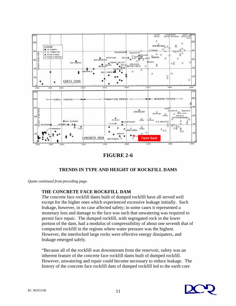
Quote continued from preceding page. Nevada Mountains. Water was required at high pressure for hydraulic sluicing in placer mining. Solid rock, talus rock and trees were available. These resources, combined with the miners' know-how in drilling and blasting rock, resulted in rock crib and timber face rockfill dams. Irrigation and power companies later took over these older dams and supplemented them with higher dams, with dumped rockfill, and with face membranes constructed of concrete rather than of timber. As late as 1940, rockfill dams were generally defined as concrete face dumped rockfill dams. At about that time, as dumped rockfills became higher; leakage was becoming troublesome, resulting in development of the earth core rockfill dam. That type has now become one of the most frequently used dam types. In the 1960s, with the advent of compacted rockfill, the concrete face rockfill gradually resumed its place among rockfill dams and, with a fine performance record; this type is currently being increasingly selected for high dams. As rockfill designs have changed, so have construction practices changed markedly worldwide, particularly during recent decades. Such progress is a direct result of ICOLD activities. That development is discussed in this section principally in relation to United States dams. It is recognized that developments in other countries followed and often paralleled those in the United States. The trend in selection of the type of rockfill dam and of heights (in meters) is shown on Figure 2-6 below (reproduced from Figure 6-1 in the reference document) for both United States and many foreign dams. As is evident, the development of the concrete face rockfill dam was primarily in the United States, followed by other countries in the late 1920s. By the late 1930s the earth core rockfill dam became popular and for about 20 years the concrete face rockfill reached a complete state of hiatus in the United States. By the 1950s, when dam building of all types increased dramatically throughout the world, both concrete face and earth core types were adopted worldwide. It is perhaps ironic that, in spite of the leadership of the United States in the development of both types of rockfill dams, the preponderance of construction of high dams of both types has, since the mid-1960s, shifted to other countries, the reason being that sites for high or major dams in the United States have been developed, as is the case for Europe and Japan. In the following text, discussions of the design trends of each type of rockfill dam are treated chronologically. Three periods are apparent from Figure 6-1 (Figure 2-6). These periods are approximately: Early Period (1900-1940), Transition Period (1940-1970), and Modern Period (1970-1988). Current practice in the use of the various features of each of the two major rockfill dam types is given…
R5 063551/06 11
FIGURE 2-6
TRENDS IN TYPE AND HEIGHT OF ROCKFILL DAMS Quote continued from preceding page.
THE CONCRETE FACE ROCKFILL DAM The concrete face rockfill dams built of dumped rockfill have all served well except for the higher ones which experienced excessive leakage initially. Such leakage, however, in no case affected safety; in some cases it represented a monetary loss and damage to the face was such that unwatering was required to permit face repair. The dumped rockfill, with segregated rock in the lower portion of the dam, had a modulus of compressibility of about one seventh that of compacted rockfill in the regions where water pressure was the highest. However, the interlocked large rocks were effective energy dissipaters, and leakage emerged safely. “Because all of the rockfill was downstream from the reservoir, safety was an inherent feature of the concrete face rockfill dams built of dumped rockfill. However, unwatering and repair could become necessary to reduce leakage. The history of the concrete face rockfill dam of dumped rockfill led to the earth core
Taum Sauk
R5 063551/06 12
Quote continued from preceding page. rockfill, where the dumped rockfill, earth core and filters were compatible. This transition to the earth core dumped rockfill is seen in Figure 6-1 (our Figure 2-6)… EARLY PERIOD (1900-1940) As stated earlier, prior to 1900, timber face rockfill dams were used for reservoirs serving placer mining, and later for irrigation and power. Edward Wegman of New York Water Supply recognized this development in "Western States of the Union" in his book. In 1899 he wrote: "Within recent years a new style of dam has come into use in the Western States of the Union. We refer to what is known as a rockfill dam, an embankment consisting of rock dumped loosely except at the faces, where it is laid carefully as by masonry… A breakthrough in height of rockfill was made in 1925 by construction of the 275-feet high Dix River Dam. The Dix River design was similar to that of other rockfill dams built after 1910: that is, it used dumped rockfill, derrick placed rock, 1H:1V to 1.2H:IV upstream slope with a reinforced concrete face, and 1.4H:1V downstream slope. The early success of Dix River Dam led to the adoption of similar design for the 328-feet high Salt Springs Dam … Completion of this dam in 1931 and of the 280-feet high Cogswell Dam in 1935 closed the 1910-1940 Period. That period also saw the adoption of the concrete face rockfill dam in other countries. In 1940 only about one-third of the world's concrete face rockfill dams were outside the United States. As a consequence of excessive leakage, measured in tens of cfs, through the high Dix River and Salt Springs Dams, the popularity of the high concrete faced dumped rockfill declined. In 1940, at the end of this early period, rockfill dams were of nearly identical design, with the following dominant features:” 1. Dumped rockfill-placed in 20- to 200-feet lifts. 2. A cutoff trench in hard rock backfilled with concrete. 3. A face zone of large derrick (crane) placed rock. 4. The face slab panels were separated by compressible filler. 5. There was a single perimeter-joint waterstop. All of these features were to be changed during the 1940-1970 transition period. The changes improved performance and reduced cost. The principal reason for the changes was experience with cracks in the concrete face, spalling at joints and other joint problems, each causing leakage. However, these dams were safe, except when overtopped.
R5 063551/06 13
Quote continued from preceding page. Nearly all are in service today, most with enlarged spillways. The most recent overtopped concrete face rockfill was Swift Dam in Montana. This dam was completed in 1915. It failed in 1964. The vital importance of an adequate spillway capacity for embankment dams was recognized as early as 1900, but the science for determining the design flood was in its infancy. DEVELOPMENT OF DAM ENGINEERING IN THE UNITED STATES TRANSITION PERIOD (1940-1970) During the 1940-1950 period, there were few dam completions because of World War II (Figure 6-1 our Figure 2-6). There were no concrete face rockfill dams and those embankment dams which were constructed were earth core rockfill, indicating a trend away from the concrete face dumped rockfill. The trend was logical because of the leakage experience previously mentioned. It was beginning to be evident to designers of high dams that the deformation characteristics of dumped rock and of concrete had not proven compatible. On the contrary, the flexibility of earth cores with filters rendered them capable of accommodating the large settlement of dumped rockfill. In the mid-1950s, there were sites that needed concrete face rockfill. Hence, the conventional design with dumped rockfill was continued for United States and foreign dams. The two highest, Paradela and Courtright, experienced excessive leakage. The leakage at both dams has since been permanently reduced to a nominal amount, but the sealing repair required unwatering… The transition from dumped to compacted rockfill for the concrete face rockfill dams and for the earth core rockfill began in 1955. Since 1967, all rockfill dams have been built with compacted rock.”
Given the above abridged history and reflecting on the Upper Reservoir Rockfill Dike (URRD), we raise the following comments. Although the URRD was completed in 1963, it did not follow the best construction practices available at the time of construction. It is RIZZO’s opinion that it followed construction practices of the late 1940’s. Specifically, the URRD was placed as a dumped rockfill dam and only the upstream (water side) concrete face was provided to reduce leakage. Given the state-of-the-practice at the time of construction, leakage through the URRD should have been expected and care should have been exercised during construction to limit the amount of fines placed within the URRD.

R5 063551/06 14
Poor behavior of dumped rockfill versus compacted rockfill was known at the time. It would appear, in hindsight, that the design was flawed and not consistent with the evolving state of the practice in the early 1960s. It is noted that the URRD was the last dumped rockfill dike built in the United States and possibly in the world (refer to Figure 2-6 shown above).
2.7 UPPER RESERVOIR DIKE DESIGN – 1963 VERSUS 2006 CONSTRUCTION PRACTICES
Considering the development of concrete-faced rockfill dams over the last century plus, it is appropriate to understand the differences between modern day (2006) design and construction practices and those followed in the late 1950s and early 1960s when the Taum Sauk Plant was being designed and constructed. This comparison bears, to some degree, on the practices to be followed in the event that the Upper Reservoir is rebuilt. The following Table 2-1 summarizes the differences as they apply to the Upper Reservoir Dike design and construction.

R5 063551/06 15
TABLE 2-1
DESIGN AND CONSTRUCTION PRACTICES TAUM SAUK VERSUS 2006
TAUM SAUK DESIGN 2006 DESIGN AND
CONSTRUCTION PRACTICES Rock was dumped and re-positioned by sluicing with water (jets) from monitors.
Rock is dumped and compacted with heavy compactors and/or heavy tracked dozers.
Fines were removed by sluicing after rock was dumped into position.
Fines are removed by screening at the borrow area.
Foundation was prepared by removal of most deleterious material by dozers. A note on the Drawings that applies to the 70 feet nearest the upstream toe reads as follows: “Strip to sound rock with not more than 2 inches (average) of dirt. This dirt to be thoroughly saturated before placing rockfill.” Another similar note that applies to the center portion of the Dike reads as follows: “Remove topsoil and loose, unstable, altered material as far as possible with bulldozer.”
Foundation is prepared by hand labor, water jets, air jets and small excavators. A great deal of detail work, including dental concrete, is often required for concrete or RCC sections. Bulldozers do not allow for enough detail work and leave too much deleterious material behind.
Parapet walls were used to retain water on an “everyday” basis.
Parapet walls are used only if necessary to act as a short-term barrier against flood levels or wave action. They are not used on an “everyday” basis.
Grout curtain was installed to a depth of about 20 feet. There is no evidence of the design basis.
Grout curtains are designed to a depth where rock is essentially impermeable and generally not less than about 30 percent to 40 percent of the sustained head.
In comparing Taum Sauk Design with current (2006) design and construction practices, we note the several deficiencies with respect to the URRD that would be very costly, and perhaps impossible, to repair through an upgrade or remediation. These include excessive fines within the rockfill, inadequate foundation preparation, lack of compactive effort during rockfill placement, and the use of the parapet wall to store water on an everyday basis.
R5 063551/06 16
We conclude from this comparison that while the design was in all likelihood consistent with the general practice of the late 1950s and early 1960s, it was not consistent with the best practices of those times and, in any case it is not adequate by today’s design and construction practices. Further to this point, we conclude that restoration of the Upper Reservoir to an operating condition following current practices can not be achieved by simply repairing the Breach Area. Restoration of the Upper Reservoir, if undertaken by AmerenUE, will necessarily involve a complete rebuild of the entire Rockfill Dike with a completely different design concept, one that is substantially more robust and capable of withstanding currently accepted earthquake loading criteria.
2.8 UPPER RESERVOIR DIKE CONSTRUCTION VERSUS DESIGN
As part of our comprehensive site reconnaissance effort with this forensic investigation, we have compared the intent of the original designer as reflected in the construction specifications with our observations. Two major observations evolved from this effort, specifically the fines content (particles of soil size as opposed to sand or gravel) of the rockfill and the preparation of the foundation. The fines content issue stands out on the slopes of the Breach Area as illustrated below on Figure 2-7, which is a photo of the north side of the Breach Area. This is supposed to be a rockfill, but it is apparent than fines were left in place and comprise a significant percentage of the overall embankment. We submit that this was not the original designer’s intent and that the shear strength and drainage properties of this finer material acts negatively on the performance of this type of dam and dike construction.
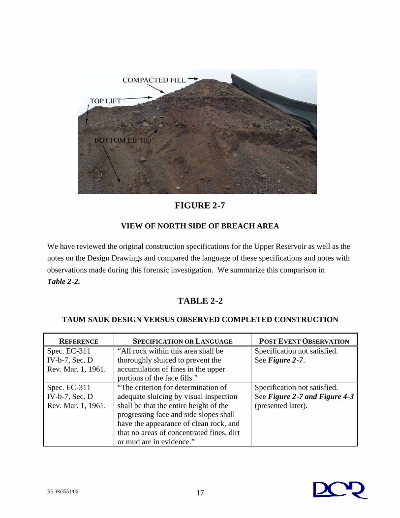
R5 063551/06 17
FIGURE 2-7
VIEW OF NORTH SIDE OF BREACH AREA
We have reviewed the original construction specifications for the Upper Reservoir as well as the notes on the Design Drawings and compared the language of these specifications and notes with observations made during this forensic investigation. We summarize this comparison in Table 2-2.
TABLE 2-2
TAUM SAUK DESIGN VERSUS OBSERVED COMPLETED CONSTRUCTION
REFERENCE SPECIFICATION OR LANGUAGE POST EVENT OBSERVATION Spec. EC-311 IV-b-7, Sec. D Rev. Mar. 1, 1961.
“All rock within this area shall be thoroughly sluiced to prevent the accumulation of fines in the upper portions of the face fills.”
Specification not satisfied. See Figure 2-7.
Spec. EC-311 IV-b-7, Sec. D Rev. Mar. 1, 1961.
“The criterion for determination of adequate sluicing by visual inspection shall be that the entire height of the progressing face and side slopes shall have the appearance of clean rock, and that no areas of concentrated fines, dirt or mud are in evidence.”
Specification not satisfied. See Figure 2-7 and Figure 4-3 (presented later).

R5 063551/06 18
TABLE 2-2 (CONTINUED)
TAUM SAUK DESIGN VERSUS OBSERVED COMPLETED CONSTRUCTION
REFERENCE SPECIFICATION OR LANGUAGE POST EVENT OBSERVATION Spec. EC-311 IV-b-5, Sec. C Rev. Mar. 1, 1961.
“The contractor shall, by control of drilling operations and strength of blasting charge, make every effort to have the rock break into as large pieces as practical for the best construction of the Rockfill Dike.”
Specification not satisfied. See Figure 2-7, and Figures 4-2 and Figure 8-5, (presented later).
Spec. EC-311 IV-b-8, Sec. E Rev. Mar. 1, 1961.
“The jetting shall accomplish, principally, the following: a) Wash surface zones of fines away. b) Excavate pockets of spalls and distribute the spalls into voids between larger rocks in contact.”
Specification not satisfied. See Figure 2-7 and Figure 4-3 (presented later).
Drawings, Typical Dike Section on Sound Rock
“Remove topsoil and loose, unstable, altered material as far as possible with bulldozer.”
Specification not satisfied in all locations. RIZZO forensic investigation borings encountered 18 inches of soil in some locations. (Refer to Appendix D).
We conclude from this comparison that the actual construction deviated significantly and in a negative manner from the intent of the original design. It is our contention that this deviation contributed to the instability of the Rockfill Dike in the Breach Area and, as later discussed in context, contributed to the root cause of the Event of December 14, 2005.
2.9 HISTORICAL PERFORMANCE OF THE UPPER RESERVOIR
During the course of our records review, we observed that the Rockfill Dike at the Upper Reservoir has had a history of incidents stemming from the original design and construction.
Leakage was a major problem immediately after first filling and slope movements have occurred over its history. These incidents have been repaired and maintained by AmerenUE on a timely
basis following good practice where dam safety and/or project economics were impacted The remediation of the 1963 event is described in a short report dated May 15, 1964 prepared by P.A.
Pickel, often referred to as the “Pickel Report” included in Appendix B.

R5 063551/06 19
2.10 THE BREACHING OF GOUHOU DAM IN QINGHAI PROVINCE, CHINA Dr. Gabriel Fernandez, a member of the AmerenUE Board of Consultants and Dr. A. J. Hendron, consultant to the FERC, brought to our attention the failure of the Gouhou Dam in China on August 27, 1993. A description of this event is available in a paper published by Mr. Zuyu Chen of the Institute of Water Conservancy and Hydroelectric Power Research. We quote several key paragraphs from his paper below and we provide the complete paper in Appendix C:
On August 27, 1993, a catastrophic dam failure happened at the Gouhou Reservoir, located near the town of Qiapogia, capital of the Gongho County, Qinghai Province. Breaching of this concrete face sand and gravel dam (CFGD) created an estimated 1,500 m3/s peak discharge of water, sweeping away half of the embankment material and bringing about great losses in human lives and properties. The Gouhou dam started water impoundment on September 28, 1989. On October of the same year, corresponding to a reservoir water level of 3258 m, a concentrated flow appeared at the downstream slope somewhere 1.5 m higher than the toe (El. 3223m). Local remedial work included replacement of the scoured fill material, after which the flow seemed to disappear. October, 1990 saw the first high reservoir water level of 3274 m. The concentrated water flow re-appeared at the same location seen in 1989. The inflow measured at the weir near the toe of the dam was l81/m3. No concentrated seepage was visualized during 1991-1992, a period whose reservoir water level was relatively low, not exceeding 3262 m (Yu. 1993). As a small project, limited instrumentation was available. It was measured that the settlement at the dam crest was 7cm. The water levels of the four open stand type piezometers of the abutment indicated that ground water level of the bed rock was lower than 3225 m, which is reasonably low. An earthquake of the magnitude 6.9 on the Richter scale hit the area on April 26, 1990 with its epicenter 40 km from the dam. The dam was found to be intact.
Failure Process Starting from July 14, the water level of the reservoir kept rising from 3261m. On August 26 the reservoir level reached 3277 m which meant that it had been close to or sometimes higher than the horizontal slab of the crest wall (same as Parapet Wall at URRD) for about 24 hours before the dam failure. It must be emphasized that this statement, which is significant in explaining the causes of the dam failure as will be seen later.
R5 063551/06 20
Destructions of the Dam The breaching of the dam created a triangle weir on the concrete face slab, which is 137 meter wide at the dam crest. The elevation of the lower point was 3250 m. Part of the slot went along the horizontal joint of the face slab. The flood cut through the dam body and created a 61 m wide chute with almost vertical side walls. Total amount of water released was estimated to be 2.61 million m3. The remaining part of the dam body lower than 3250 m kept retaining water which overtopped the crest and created a water fall… Discussions and Concluding Remarks It is clear that the failure of the Gouhou dam was caused by the unexpected high phreatic line of the dam. Water came into the dam through damaged concrete slabs and their joints especially when it exceeds the slab of the crest wall. The fill material seemed to be not permeable enough to allow free draining…”
We find the failure of Gouhou Dam as described in this paper to strongly parallel the behavior of the Rockfill Dike at the Breach Area of the Upper Reservoir. As seen below in context, we treat a high phreatic surface caused by leakage through the face as Condition A in our stability analysis. As seen later in context, the cause of the failure of Gouhou Dam supports our interpretation of the root cause of the failure of the Upper Reservoir Dike at Taum Sauk.


![In the Appalacian Region August 2009 Lexington, KY · 12/14/2005 · – – Johnson Shut-ins State Park – ... FERC Website Information – [search Taum Sauk] –Executive Summary](https://img.pdfslide.us/doc/110x75/5fed79c0940d6c10ca42d51c/in-the-appalacian-region-august-2009-lexington-ky-12142005-a-a-johnson.jpg)