Embed Size (px)
Citation preview
1.0 DESCRIPTION
user can re-con gure the transmitter parameters by use of a single push button and the range“R” , menu “M” LEDS. Two methods of con guration are available, the rst “USER RANGING”acts only on the transmitter range, similar to the previous 659TC-1 design. The othermethod “ADVANCED USER CONFIGURATION” o ers full con guration. This level is entered byby holding down the push button on power up. The advanced level has the following menus:-
• Menu 1 - Selection of input type, seven popular thermocouples or mV input.• Menu 2 - Select either user push button set range or one of seven xed ranges.
• Menu 3 - Select either up or down scale output on sensor burnout.• Menu 4 - User trim allow trim of output current at high and low range• Menu 5 - Reset factory default.
The addition of xed ranges to this product allows the used to re-range the product without theneed for specialist equipment. The 659TC-1 input is isolated.
2.0 RECEIVING AND UNPACKING
Please inspect the packaging and instrument thoroughly for any signs of transit damage. If theinstrument has been damaged, please notify your supplier immediately.
3.0 SPECIFICATION @ 20 °C
INPUT
Sensor Range (°C ) ycaruccA
K -200 to 1370 ± 0.1% of F.S. ± 0.5 °C(plus any sensor error)
J -100 to 1200 ± 0.1% of F.S. ± 0.5 °C(plus any sensor error)
E -100 to 1000 ± 0.1% of F.S. ± 0.5 °C(plus any sensor error)
N -180 to 1300 ± 0.1% of F.S. ± 0.5 °C(plus any sensor error)
T -100 to 400 ± 0.2% of F.S. ± 0.5 °C(plus any sensor error)
R -10 to 1760 ± 0.1% of F.S. ± 0.5 °C(plus any sensor error) over range 800 to 1600
S -10 to 1760 ± 0.1% of F.S. ± 0.5 °C(plus any sensor error) over range 800 to 1600
Range (mV)
mV elacs lluf fo %20.0 ±07 ot 01-
Isolation Tested to 250VDCSensor Burnout Either up or down scale outputCold Junction Range -40 to 85 °C; Accuracy ± 0.5 °C
Tracking ± 0.05 °C / °CStability O set 0.1 °C / °C ; Span 0.05 °C / °C
OUTPUT
Type Two wire 4 to 20mA sinkLimits Low 3.8mA ; high 21.5mAAccuracy (mA out / 2000) or 5uA which ever greaterLoop E ect ± 0.2 uA / V measured @ 50 Hz 1V (peak to peak)Thermal Drift ± 1uA / °C typical ; ±1.5 uA MaxMax Load [(Vsupply – 10)/20] K Ω
GENERAL
Update Time 0.5 SecondsResponse Time 1 Second to reach 90% of nal valueStart up time From power up typically 5 SecondsFilter Factor AdaptiveAmbient Temperature -40 to 85 °CConnection Screw TerminalApproval BS EN 61326 ; 1998 – Electrical equipment for measurement
and control ANNEX A ; ANNEX FFactory Default 0 to 1000 °C type K, upscale burnout 0.0 °C user trim
4.0 INSTALLATION AND WIRING
4.1 Mechanical
The transmitter has been speci cally designed to t inside a DIN standard probehead enclosure (such as the Status SCH-4 series), which provides adequate protection frommoisture, dust, corrosive atmosphere etc. All cable entries must be sealed using the correctsize gland. Likewise any probe assembly tted must be sealed.Care must be taken when locating the transmitter to ensure the working ambient temperaturerange of -40 to 85 °C is not exceeded. The 659TC-1 enclosure has a center hole allowingthe sensor wired to enter screw terminals from the transmitter center, this is applicable whenthe sensor is mounted directly below the transmitter.
Figure 1
Mounting holes : two holes 5.5mm diameter, 33mm centersCenter Hole sensor wire entry : 4mm
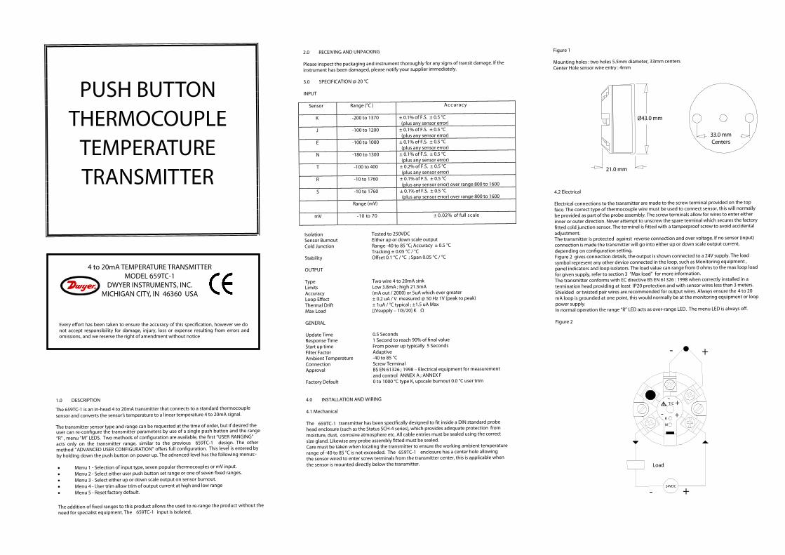
4.2 Electrical
Electrical connections to the transmitter are made to the screw terminal provided on the topface. The correct type of thermocouple wire must be used to connect sensor, this will normally be provided as part of the probe assembly. The screw terminals allow for wires to enter eitherinner or outer direction. Never attempt to unscrew the spare terminal which secures the factory
tted cold junction sensor. The terminal is tted with a tamperproof screw to avoid accidentaladjustment.The transmitter is protected against reverse connection and over voltage. If no sensor (input)connection is made the transmitter will go into either up or down scale output current,depending on con guration setting.Figure 2 gives connection details, the output is shown connected to a 24V supply. The loadsymbol represent any other device connected in the loop, such as Monitoring equipment ,panel indicators and loop isolators. The load value can range from 0 ohms to the max loop loadfor given supply, refer to section 3 “Max load” for more information.The transmitter conforms with EC directive BS EN 61326 : 1998 when correctly installed in atermination head providing at least IP20 protection and with sensor wires less than 3 meters.Shielded or twisted pair wires are recommended for output wires. Always ensure the 4 to 20 mA loop is grounded at one point, this would normally be at the monitoring equipment or looppower supply.In normal operation the range “R” LED acts as over-range LED. The menu LED is always o .
Figure 2
Every e ort has been taken to ensure the accuracy of this speci cation, however we donot accept responsibility for damage, injury, loss or expense resulting from errors andomissions, and we reserve the right of amendment without notice
Ø43.0 mm
21.0 mm
33.0 mmCent
- +
Load
- +
R
M
-T/C
- +
+
THERMOCOUPLETEMPERATURETRANSMITTER
PUSH BUTTON
4 to 20mA TEMPERATURE TRANSMITTERMODEL 659TC-1
DWYER INSTRUMENTS, INC.MICHIGAN CITY, IN 46360 USA
The 659TC-1 is an in-head 4 to 20mA transmitter that connects to a standard thermocouple
sensor and converts the sensor’s temperature to a linear temperature 4 to 20mA signal.
The transmitter sensor type and range can be requested at the time of order, but if desired the 659TC-1
24VDC
ers

5.0 USER RANGINGThe transmitter may be purchased pre-con gured, if speci ed at the time of order. Userranging is provided to allow the temperature range of the transmitter to be set to a customrange. This con guration level cannot change the input type, If the input type or otherparameters require change, then please refer to the advances con guration section. To con rmthe present input type set on the transmitter is correct for your application, count the number of
ashes of the range “R” LED at power up then refer to the chart in section 6 “Menu 1” toestablish the type set.
The push button is located under the slot in the key hole label, the slot located next to themenu “M” LED . To press the button use a 3 mm screw driver ( at blade), inserted into the slotand locate resistance of button key. The button has a slight click action.
It may be worth noting at this stage the advance user con guration provides the user with theoption of selecting xed ranges, this may be a more attractive option if a suitable range isavailable, as no calibration equipment will be required.
Con guration will require the following tools and equipment :-
• DC Supply 12 to 30 @ 30 mA• Thermocouple calibrator• Thermocouple compensating wire• Screw driver at blade 3mm wide
To re-range the temperature scale follow the following instructions:-
• Connect thermocouple calibrator to input terminals using correctthermocouple compensation wire. Observe polarity.
• Connect the output terminals to the DC supply, observe polarity.• Turn DC supply on.• Set calibrator to the required low scale temperature. Note Range “R” LED if on
indicates input connection error or i nput out of range, please check input.• Allow 1 minute warm up period.• To “enter” ranging, press and keep pressed the push button until Range “R” LED
ashes at a slow rate, then release button• .The “R ” LED will ash at a slow rate for a approximately one second during which
period the low scale range is stored. Once the store is complete the “R” LED will ashat a medium rate indicating the transmitter is ready to store the high range setting.
• Set the calibrator to the required high range temperature and allow ten seconds.• Press button to store high range setting, the “R” LED will icker for one second before
the transmitter returns to normal operation. The transmitter is now re-ranged.
The above procedure also applies to mV input, but please ensure only copper wire is used forconnection to mV calibrator.
6.0 ADVANCED USER CONFIGURATION
The advanced user con guration option is based on ve menus, each menuSets a di erent parameter:-
Menu 1 Selects one of eight input types.Menu 2 Selects either custom user range or one of seven xed range.Menu 3 Selects the output direction of sensor burnout. Menu 4 Provide User trim at 4mA and 20 mA.Menu 5 Reset to factory default setting.
The advance con guration menus are navigated using the push button, menu “M” LED andrange “R” LED , The push button is located underneath the slot in the key hole label, locatedjust below the “M” LED. To press the button use a 3 mm screw driver ( at blade) inserted intothe slot. The button has a slight click action.Three commands are used to navigate menus, performed by clicking the button as follows:-
• kcilc ro sserp nottub elgniS ecnavdA • Escape or change direction Double press or click within 0.5 seconds• sdnoces owt > nottub dloh dna sserPretnE
When a menu is selected the “M” LED will ash a burst of 1 to 5 ashes, the number ofashes represents the menu number.
Note the range “R “ LED will only operate when a selected menu has been entered, then the“R” LED uses a series of ashes or toggle ash rates to indicate the state or stage of the openmenu.
Navigating the menus (Read all of this section before attempting con guration)
To access the advanced user menus press and hold down button during power up.The advance user menus will now be enabled and remain enabled until transmitter power isremoved. Note the “USER RANGING ” level will not be active at this stage, the push button willnow serve to navigate “advance user menus” as follows:-
• To “enter” menus press and hold button for > 2 seconds. The “M” LED will then startsto ash, rate one ash per burst (indicating menu 1).
• To “advance” to the next menu use single button press, the “M” LED will advance totwo ashes per burst, indicating menu 2 is selected. Repeated single presses willadvance menu, once menu 5 is reached, the next press will returns to menu 1, for arepeat cycle around the menus.
• To “escape” from menus back to normal operation use a double click of the button orremove transmitter power. Note menus have no timeout escape and therefore willremain selected inde nitely.
• To “enter” a selected menus press and hold button for two seconds, at which stage the“R” LED will start to ash between bursts of the “M” LED, indicating the state of theopened menu.
MENUS (First Select the required menu and open as described above.)
Menu 1 Input type
• On Entry “M” LED single ash every burst (menu 1), followed by a burst of between 1to 8 “R” LED ashes, ash count represents the input type as listed below. Timeout is10 seconds so be sure to act quickly if the type needs changing.
“R “ LED ashes Input Type
1 Type K2 Type J3 Type E4 Type N5 Type T6 Type R7 Type S8 mV
• Single button press to “advance” to the next input type, when type 8 is reached thenext “advance” will cycle back to type 1. To ensure valid indication of input menu,allow one to two burst cycle after advance”, before counting the “R” LED ashes.
• Once the desired type is selected, allow 10 seconds with no button action, thetransmitter will then store the selected input type, (indicated by icker of “R” LED)before return back to normal operation.
Menu 2 Fixed ranges
• On “ Entry” the “M” LED ashes twice every burst (menu2), followed by a “R” LEDashes between 1 to 8 , ash count represents the range selected as described below.
Timeout is 10 seconds so be quick to act.• Range 1 is allocated for the user custom push button set range. When a new custom
range (see USER RANGING) is entered, the range selected will automatically return to1.
Range “R”LEDashes
InputsK,J,E, & N
(°C)
InputT
(°C)
InputsR, & S
(°C)
Input mV
mV
1 User Ranged2 0 to 1000 0 to 400 800 to 1760 0 to 703 0 to 1200 0 to 250 800 to 1600 0 to 54 0 to 600 0 to 200 800 to 1400 0 to 105 0 to 500 0 to 150 1000 to 1760 0 to 206 0 to 250 O to 100 1000 to 1600 0 to 257 0 to 100 0 to 50 1000 to 1400 0 to 508 -100 to 100 -100 to 100 0 to 1600 -10 to 10
• Single button press to “advance” to the next range, once range 8 is reached, the next“advance” will cycle range back to 1. To ensure valid indication of range menu, allowone to two burst cycle after ”advance” , before counting ashes.
• Once the desired range is selected allow for 10 seconds with no button action, thetransmitter will then store new range (indicated by icker of “R” LED) before returningto normal operation.
Menu 3 Burnout Selection
• On “Entry” - “M” LED, three ashes every burst (menu 3), followed by a “R” LED toggleash, either at a slow rate (every second) or a faster medium rate. Be quick to act as
timeout is 10 seconds.• Slow rate indicated low scale burnout , fast rate indicates upscale burnout.• To “advance ” to the the other burnout direction press button.• To store new setting allow 10 seconds with no button action, the burn out selsction
menu will then timeout, store new setting, (indicated by a icker of the “R” LED),before returning back to normal operation.
Menu 4 User trim
This menu allows the user to trim the output current at zero and span, (similar functionto trim potentiometers) and is very useful for trimming out sensor errors.The input of the transmitter must be connected to either a calibrator or a temperaturesensor held at a known temperature. The 4 to mA loop current will also need to bemonitored with a current meter. This menu has extended timeout of 20 seconds.
• The trim action will only operate within certain output current bands, the zero will betrimmed when the out current is between (3.8 to 6.0) mA, and the span will be trimmedwhen the output current is between (18.0 to 21.5) mA.
• On “Entry” - “M” LED, four ashes every burst (menu 4), followed by a “R” LED toggleash, either at a slow rate (every second) or a faster medium rate.
• Slow rate indicates trim direct down, while fast rate indicate trim direction up.• To “change direction” double click button.• To trim, single press button to “advance” current by 2 uA, or press and hold button to
auto advance, after two seconds the trim will adjust automatically at a rate of 3 uA persecond until the button is released. Note after approximately 20 seconds of continuousbutton press, the auto trim rate will speed up to a rate of 10 uA per second.
• To store new setting allow 20 seconds with no button action, the User Trim menu willthen timeout and store any new setting(s), (indicated by a icker of the “R” LED),before returning back to normal operation.
Menu 5 Set factory default
• On “Entry” - “M” LED, ve ashes every burst (menu 5), followed by “R” LED toggleash at a slow rate (every second).
• To set factory default and zero any user trim, press button. Default setting will then beloaded and stored into the transmitter, indicated by a icker of the “R” LED. Thetransmitter will then return to normal operation.
• To avoid any action, allow 10 seconds with no button action, Set factory default menuwill then timeout, without storing any default con guration. The transmitter will thenreturn to normal operation.
VDC
659TC-1
659TC-1
“
20
trim