Embed Size (px)
Citation preview
Pico Power Project AFC, Vol. I 2-1 Project Description
2.0 PROJECT DESCRIPTION
2.1 INTRODUCTIONThe Silicon Valley Power Pico Power Project (PPP) will be a 122-megawatt (MW) nominal net output,natural gas-fired, combined-cycle electrical generating facility, with the ability to peak-fire to 147 MW,connected to a 115-kilovolt (kV) switchyard. The PPP will be located on approximately 2.86 acres at 850Duane Avenue in the City of Santa Clara, in Santa Clara County. A gas compressor station for the projectwill be located on the City of Santa Clara’s maintenance yard, a 0.26-acre parcel at the corner ofLafayette and Comstock Streets in Santa Clara.
2.2 PPP DESCRIPTION, DESIGN, AND OPERATIONThis section describes the design and operational characteristics of the proposed PPP plant.
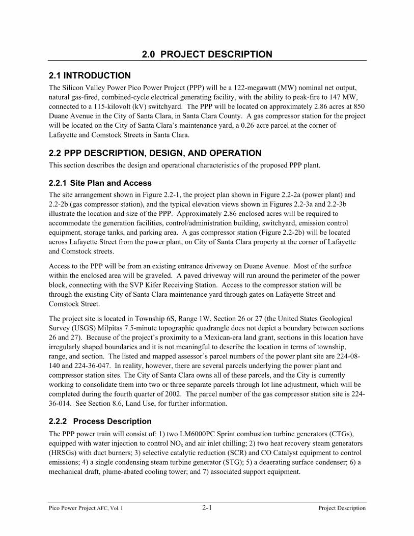
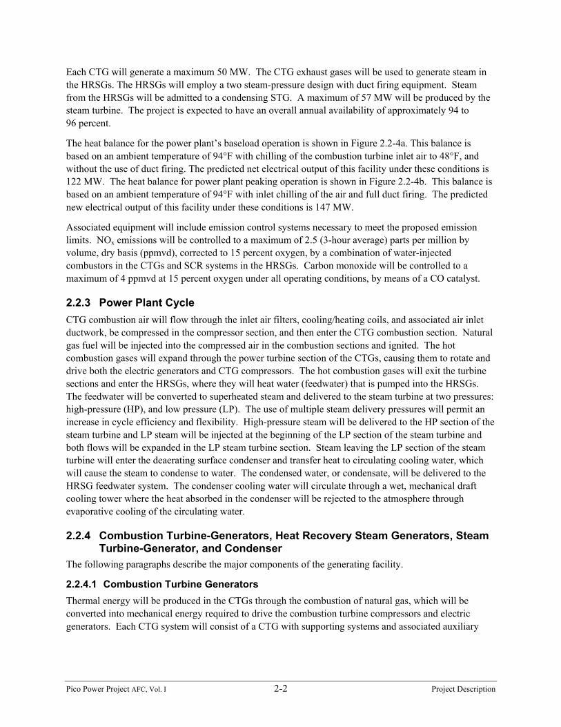
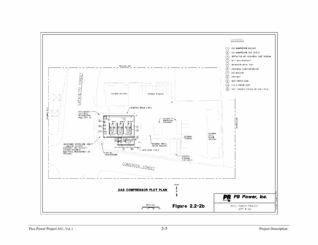
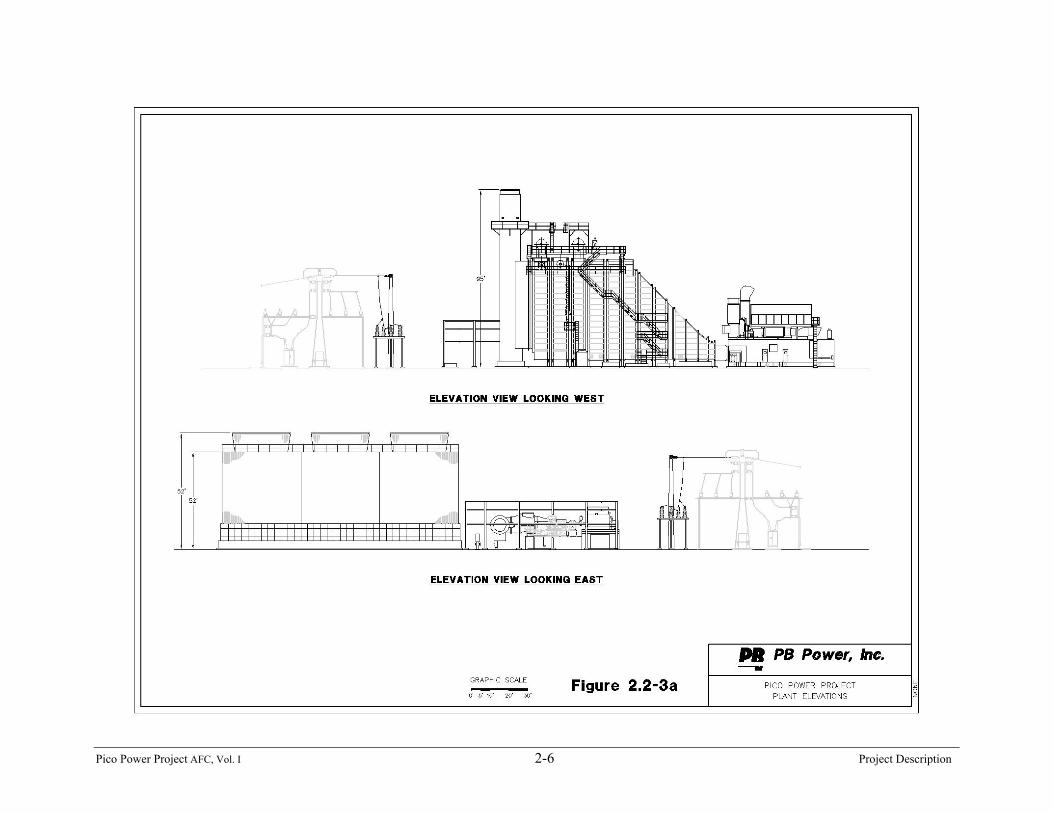
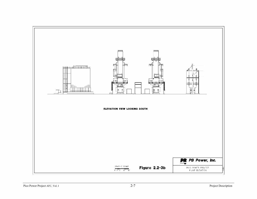
2.2.1 Site Plan and Access The site arrangement shown in Figure 2.2-1, the project plan shown in Figure 2.2-2a (power plant) and2.2-2b (gas compressor station), and the typical elevation views shown in Figures 2.2-3a and 2.2-3billustrate the location and size of the PPP. Approximately 2.86 enclosed acres will be required toaccommodate the generation facilities, control/administration building, switchyard, emission controlequipment, storage tanks, and parking area. A gas compressor station (Figure 2.2-2b) will be locatedacross Lafayette Street from the power plant, on City of Santa Clara property at the corner of Lafayetteand Comstock streets.
Access to the PPP will be from an existing entrance driveway on Duane Avenue. Most of the surfacewithin the enclosed area will be graveled. A paved driveway will run around the perimeter of the powerblock, connecting with the SVP Kifer Receiving Station. Access to the compressor station will bethrough the existing City of Santa Clara maintenance yard through gates on Lafayette Street andComstock Street.
The project site is located in Township 6S, Range 1W, Section 26 or 27 (the United States GeologicalSurvey (USGS) Milpitas 7.5-minute topographic quadrangle does not depict a boundary between sections26 and 27). Because of the project’s proximity to a Mexican-era land grant, sections in this location haveirregularly shaped boundaries and it is not meaningful to describe the location in terms of township,range, and section. The listed and mapped assessor’s parcel numbers of the power plant site are 224-08-140 and 224-36-047. In reality, however, there are several parcels underlying the power plant andcompressor station sites. The City of Santa Clara owns all of these parcels, and the City is currentlyworking to consolidate them into two or three separate parcels through lot line adjustment, which will becompleted during the fourth quarter of 2002. The parcel number of the gas compressor station site is 224-36-014. See Section 8.6, Land Use, for further information.
2.2.2 Process Description The PPP power train will consist of: 1) two LM6000PC Sprint combustion turbine generators (CTGs),equipped with water injection to control NOx and air inlet chilling; 2) two heat recovery steam generators(HRSGs) with duct burners; 3) selective catalytic reduction (SCR) and CO Catalyst equipment to controlemissions; 4) a single condensing steam turbine generator (STG); 5) a deaerating surface condenser; 6) amechanical draft, plume-abated cooling tower; and 7) associated support equipment.
Pico Power Project AFC, Vol. I 2-2 Project Description
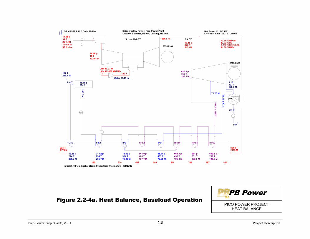
Each CTG will generate a maximum 50 MW. The CTG exhaust gases will be used to generate steam inthe HRSGs. The HRSGs will employ a two steam-pressure design with duct firing equipment. Steamfrom the HRSGs will be admitted to a condensing STG. A maximum of 57 MW will be produced by thesteam turbine. The project is expected to have an overall annual availability of approximately 94 to96 percent.
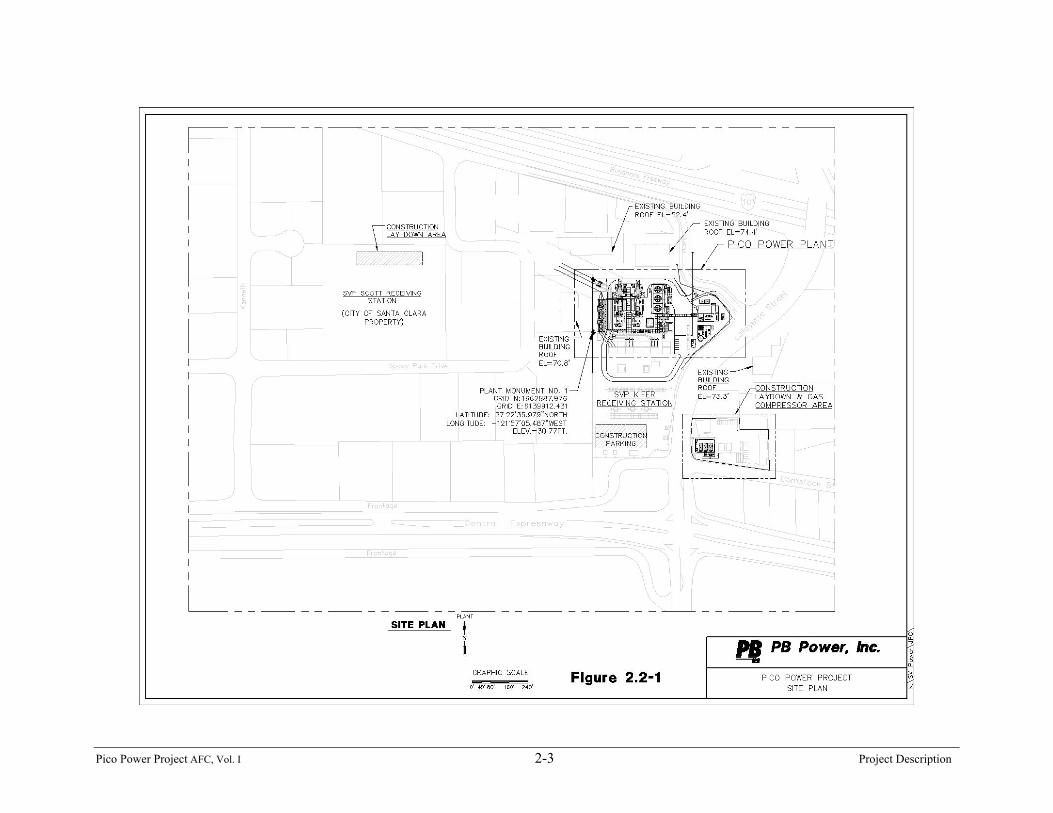
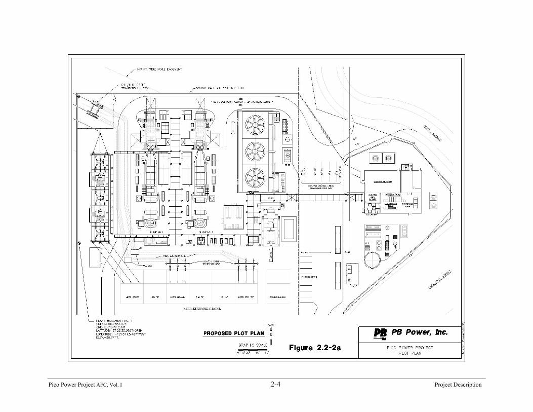
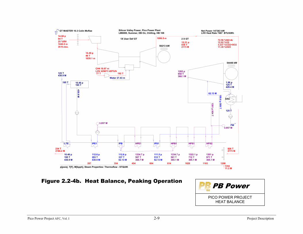
The heat balance for the power plant’s baseload operation is shown in Figure 2.2-4a. This balance isbased on an ambient temperature of 94°F with chilling of the combustion turbine inlet air to 48°F, andwithout the use of duct firing. The predicted net electrical output of this facility under these conditions is122 MW. The heat balance for power plant peaking operation is shown in Figure 2.2-4b. This balance isbased on an ambient temperature of 94°F with inlet chilling of the air and full duct firing. The predictednew electrical output of this facility under these conditions is 147 MW.
Associated equipment will include emission control systems necessary to meet the proposed emissionlimits. NOx emissions will be controlled to a maximum of 2.5 (3-hour average) parts per million byvolume, dry basis (ppmvd), corrected to 15 percent oxygen, by a combination of water-injectedcombustors in the CTGs and SCR systems in the HRSGs. Carbon monoxide will be controlled to amaximum of 4 ppmvd at 15 percent oxygen under all operating conditions, by means of a CO catalyst.
2.2.3 Power Plant Cycle CTG combustion air will flow through the inlet air filters, cooling/heating coils, and associated air inletductwork, be compressed in the compressor section, and then enter the CTG combustion section. Naturalgas fuel will be injected into the compressed air in the combustion sections and ignited. The hotcombustion gases will expand through the power turbine section of the CTGs, causing them to rotate anddrive both the electric generators and CTG compressors. The hot combustion gases will exit the turbinesections and enter the HRSGs, where they will heat water (feedwater) that is pumped into the HRSGs.The feedwater will be converted to superheated steam and delivered to the steam turbine at two pressures:high-pressure (HP), and low pressure (LP). The use of multiple steam delivery pressures will permit anincrease in cycle efficiency and flexibility. High-pressure steam will be delivered to the HP section of thesteam turbine and LP steam will be injected at the beginning of the LP section of the steam turbine andboth flows will be expanded in the LP steam turbine section. Steam leaving the LP section of the steamturbine will enter the deaerating surface condenser and transfer heat to circulating cooling water, whichwill cause the steam to condense to water. The condensed water, or condensate, will be delivered to theHRSG feedwater system. The condenser cooling water will circulate through a wet, mechanical draftcooling tower where the heat absorbed in the condenser will be rejected to the atmosphere throughevaporative cooling of the circulating water.
2.2.4 Combustion Turbine-Generators, Heat Recovery Steam Generators, SteamTurbine-Generator, and Condenser
The following paragraphs describe the major components of the generating facility.
2.2.4.1 Combustion Turbine Generators Thermal energy will be produced in the CTGs through the combustion of natural gas, which will beconverted into mechanical energy required to drive the combustion turbine compressors and electricgenerators. Each CTG system will consist of a CTG with supporting systems and associated auxiliary
Pico Power Project AFC, Vol. I 2-3 Project Description
Pico Power Project AFC, Vol. I 2-4 Project Description
Pico Power Project AFC, Vol. I 2-5 Project Description
Pico Power Project AFC, Vol. I 2-6 Project Description
Pico Power Project AFC, Vol. I 2-7 Project Description
Pico Power Project AFC, Vol. I 2-8 Project Description
GT MASTER 10.3 Colin McRae
Silicon Valley Power, Pico Power PlantLM6000, Summer, DB Off, Chilling, HB 109
Net Power 121847 kWLHV Heat Rate 7053 BTU/kWh
p[psia], T[F], M[kpph], Steam Properties: Thermoflow - STQUIK
1X User Def GT 2 X GT
50389 kW
14.68 p 94 T 25 %RH 1040.5 m 35 ft elev.
14.46 p 48 T 1039.1 m
CH4 19.97 m
192 T 77 TLHV 429667 kBTU/h
Water 27.41 m
1086.5 m
15.15 p 828 T 2173 M
72.56 %N2+Ar 12.82 %O2 3.237 %CO2+SO2 11.39 %H2O
824 T 2173 M
824 797 763 518 509 437 324 285
234 T 2173 M
27936 kW
DAC
FW
1.16 p 107 T 265.5 M
107 T
15.15 p 214 T 266.7 M
LTE
107 T 266.7 M
214 T 15.15 p 214 T
266.7 M
71.02 p 294 T 266.7 M
IPE1
71.02 p 304 T 70.25 M
IPB
68.94 p 435 T 70.25 M
IPS1
668.9 p 488 T 197.7 M
HPE1
668.8 p 498 T 195.8 M
HPB1
661 p 631 T 195.8 M
HPS1
649.3 p 769 T 195.8 M
HPS2
630.4 p 765 T 195.8 M
649.3 p 769 T 70.25 M 65.06 p 432 T
Figure 2.2-4a. Heat Balance, Baseload OperationPB Power
PICO POWER PROJECTHEAT BALANCE
Pico Power Project AFC, Vol. I 2-9 Project Description
GT MASTER 10.3 Colin McRae Silicon Valley Power, Pico Power PlantLM6000, Summer, DB On, Chilling, HB 108
Net Power 147363 kWLHV Heat Rate 7467 BTU/kWh
p[psia], T[F], M[kpph], Steam Properties: Thermoflow - STQUIK
1X User Def GT 2 X GT
50213 kW
14.68 p 94 T 25 %RH 1040.5 m 35 ft elev.
14.46 p 48 T 1039.1 m
CH4 19.97 m
192 T 77 TLHV 429673 kBTU/h
Water 27.43 m
1086.5 m
15.21 p 830 T 2173 M
72.56 %N2+Ar 12.82 %O2 3.237 %CO2+SO2 11.39 %H2O
826 T 2173 M
1200 1103 1026 614 604 454 354 287
234 T 2184.2 M
54448 kW
DAC
FW
1.96 p 125 T 429.4 M
125 T
CH4 11.2 M
10.46 p 195 T 430.9 M
LTE
125 T 430.9 M
195 T 10.46 p 195 T
430.9 M
112.6 p 283 T 430.9 M
IPE1
112.6 p 337 T 62.13 M
IPB
111.5 p 512 T 62.13 M
IPS1
1334.7 p 507 T 368.7 M
HPE1
1334.7 p 581 T 365.1 M
HPB1
1322.1 p 712 T 365.1 M
HPS1
1301 p 971 T 365.1 M
HPS2
1263 p 950 T 368.1 M
1301 p 954 T
3.057 M
3.057 M
62.13 M 109.6 p 509 T
Figure 2.2-4b. Heat Balance, Peaking OperationPB Power
PICO POWER PROJECTHEAT BALANCE
Pico Power Project AFC, Vol. I 2-10 Project Description
equipment. The CTGs will have water injection into the low pressure compressor, into the high pressurecompressor, and into the combustors to increase power and lower NOx emissions.
The CTGs will be equipped with the following required accessories to provide safe and reliable operation:
• Inlet air chilling/heating system
• Inlet air filters
• Metal acoustical enclosure
• Two lube oil systems, one for the combustion turbine and one for the generator
• Water injected low NOx combustion system
• Sprint Power Boost System
• Compressor wash system-both online and offline
• Fire detection and protection system (utilizing carbon dioxide)
• Fuel gas system, including flow meter, strainer, and duplex filter
• Starter System
• Turbine controls
• Direct-air-cooled synchronous generators
• Generator controls, protection, excitation, power system stabilizer, and automatic generationcontrol (AGC)
The CTGs and accessory equipment will be contained in a metal acoustical enclosure.
2.2.4.2 Heat Recovery Steam GeneratorsThe HRSGs will transfer heat from the exhaust gases of the CTGs to the feedwater, which will becomesteam. The HRSGs will be two-pressure, natural circulation units equipped with inlet and outletductwork, duct burners, insulation, lagging, and separate exhaust stacks.
Major heat transfer components of each HRSG will include an LP economizer, LP evaporator, LP drum,LP superheater, HP economizer, HP evaporator, HP drum, and HP superheaters. The LP economizer willreceive condensate from the condenser hot well via the condensate pumps. The LP economizer will bethe final heat transfer section to receive heat from the combustion gases before they are exhausted to theatmosphere.
Condensate will be directed through the LP economizer then split between the HP boiler feed pumps andthe LP drum. The boiler HP feed pumps will provide additional pressure to serve the HP sections of theHRSG. Similarly, as described above, the LP and HP steam will be produced for supply to the steamturbine.
Feedwater from the LP economizer which is pumped by the HP boiler feed pumps will be sent to the HPsection of the HRSG. High-pressure feedwater will flow through the HP economizers to the HP steamdrum, where a saturated liquid state will be maintained. Next, the saturated water will flow from thesteam drum through downcomers to the inlet headers of the HP evaporator. The saturated water will flowupward through the HP evaporator tubes by natural circulation. Saturated steam will form in the tubeswhile energy from the combustion turbine exhaust gas is absorbed. The HP-saturated liquid/vapormixture will then return to the steam drum, where the two phases will be separated by the steam
Pico Power Project AFC, Vol. I 2-11 Project Description
separators in the drum. The saturated water will return to the HP evaporator while the vapor passes to theHP superheater inlet. The saturated steam (vapor) will pass through the HP superheater to the HP steamturbine entrance.
Feedwater from the LP economizer will also be sent to the LP section of the HRSG. This LP feedwaterwill flow to the LP steam drum where a saturated liquid state will be maintained. Next, the saturatedwater will flow from the steam drum through downcomers to the inlet headers of the LP evaporator. Thesaturated water will flow upward through the LP evaporator tubes by natural circulation. Saturated steamwill form in the tubes as energy from the combustion turbine exhaust gas is absorbed. The LP-saturatedliquid/vapor mixture will then return to the steam drum where the two phases will be separated. Thesaturated water will return to the LP evaporator, while the vapor passes to the LP superheater inlet. Thesaturated steam (vapor) will pass through the LP superheater to the LP steam turbine entrance.
Duct burners will be installed in the HRSGs. These burners will provide the capability to increase steamgeneration, increase operating flexibility, and improve steam temperature control. The duct burners willburn natural gas. The duct burner for each HRSG will be sized to release up to 136.9 million Britishthermal units (mmBtu higher heating value or HHV basis) per hour per HRSG.
The HRSGs will be equipped with an SCR emission control system that will use ammonia vapor in thepresence of a catalyst to reduce the NOx concentration in the exhaust gases. The catalyst module will belocated in the HRSG casing. Diluted ammonia vapor (NH3) will be injected into the exhaust gas streamthrough a grid of nozzles located upstream of the catalyst module. The subsequent chemical reaction willreduce NOx to nitrogen and water, reducing the NOx concentration of no more than 2.5 (annual averagebasis) ppmvd at 15 percent oxygen (O2) in the HRSG exhaust gas. A CO catalyst will control COemissions to 4.0 ppm (annual average).
2.2.4.3 Steam Turbine SystemThe steam turbine system will consist of a condensing steam turbine, gland steam system, lubricating oilsystem, hydraulic control system, and steam admission/induction valving. The steam turbine will drive aTotally Enclosed Water/Air-Cooled (TEWAC) synchronous generator.
Steam from the HRSG HP and LP superheaters will enter the respective steam turbine sections throughthe inlet steam system. The steam will expand through the turbine blading, driving the generator. Onexiting the turbine, the remaining steam will flow into the condenser.
2.2.5 Major Electrical Equipment and SystemsThe electric power produced by the facility will be transmitted to the Silicon Valley Power grid. Somepower will be used on-site to power auxiliaries such as gas compressors, pumps and fans, control systems,and general facility loads, including lighting, heating, and air conditioning. Some will also be convertedfrom alternating current (AC) to direct current (DC) for use as backup power for control systems and forother uses. Transmission and auxiliary uses are discussed in the following subsections.
2.2.5.1 AC Power TransmissionPower will be generated by the two CTGs at 13.8 kV, and one STG at 13.8 kV. An overall single-linediagram of the facility’s electrical system is shown in Figure 6.2-1. The generator output will beconnected by cable bus to two oil-filled, three winding generator step-up transformers, which willincrease the voltage to 115 kV. Surge arresters will be provided at the high-voltage bushings to protectthe transformers from surges on the 115 kV system caused by lightning strikes or other system
Pico Power Project AFC, Vol. I 2-12 Project Description
disturbances. The transformers will be set on concrete pads within containments, which will contain thetransformer oil in the event of a leak or spill. The high voltage side of each step-up transformer will beconnected to the SVP Scott to Kifer line via a three-breaker arrangement at the plant’s on-site 115 kVswitchyard. From the switchyard, power will be transmitted through the Scott and Kifer 115 kVReceiving Stations, both owned and operated by Silicon Valley Power.
2.2.5.2 AC Power Distribution to AuxiliariesThe facility will have two sources of power for the auxiliary system. Auxiliary power to the combustionturbine and steam turbine power block will be supplied by a 4160- and 480-volt AC switchgear lineup.Power to the switchgear will be supplied by one oil-filled 13.8 to 4.16 kV Station Auxiliary Transformers,or, upon loss of the 115 kV transmission system, by one 12 kV to 4.16 kV Station Service Transformerfed from an off-site 12 kV source. The high voltage sides (13.8 kV) of the Auxiliary Transformers willbe connected to one of the CTGs. Normally, these connections will allow the switchgear to receivepower generated by the connected CTG or by back feeding power from the 115 kV switchyard via theconnected CTG’s step-up transformer. The plant design will provide for starting up the plant from the off-site 12 kV source should the 115 kV system become unavailable. Once the plant is on line, operating inthe islanded mode with the SVP transmission system, the plant’s auxiliary system will be transferred tothe Station Auxiliary Transformer (normal source) via fast transfer, supervised by a power transfer relay.
The 4,160-volt switchgear lineup will supply power to the various 4,000-volt motors and to the loadcenter (LC) transformers rated 4160 to 480 volts for 480-volt power distribution. The switchgear willhave vacuum breakers for the main incoming feeds and for power distribution, and fused contactors formotor feeds.
The LC transformers will be of the dry type if located inside and will be of the oil-filled type if locatedoutside. Each transformer will supply 480-volt, three-phase power to LC switchgear. The LC switchgearwill provide power through feeder breakers to the various 480-volt motor control centers (MCCs). TheMCCs will distribute power to 480-volt motors, to 480-volt power panels, and to other intermediate480-volt loads. The MCCs will distribute power to 480-480/240-volt isolation transformers when277-volt, single-phase lighting loads are to be served. The 480-volt power panels will distribute power tosmall 480-volt loads.
Power for the AC power supply (120-volt/208-volt) system will be provided by the 480-volt MCCs and480-volt power panels. Transformation of 480-volt power to 120/208-volt power will be provided by480-120/208-volt dry-type transformers.
2.2.5.3 DC Power SupplyOne common DC power supply system consisting of one 120-volt DC battery, two 100 percent 125-voltDC full-capacity battery chargers, metering, ground detectors, and distribution panels will be supplied forbalance-of-plant and steam turbine equipment.
Under normal operating conditions, the battery chargers will supply DC power to the DC loads. Thebattery chargers will receive 480-volt, three-phase AC power from the AC power supply (480-volt)system and continuously charge the battery. The ground detection scheme will detect grounds on the DCpower supply system.
Under abnormal or emergency conditions, when power from the AC power supply (480-volt) system isunavailable, the battery itself, rather than the charger, will provide DC power for the DC system loads.Recharging of a discharged battery will occur whenever 480-volt power becomes available from the AC
Pico Power Project AFC, Vol. I 2-13 Project Description
power supply (480-volt) system. The rate of charge will depend on the characteristics of the battery,battery charger, and connected DC load during charging. The anticipated maximum recharge time will be24 hours.
The 120-volt DC system will also be used to provide control power to the 480-volt switchgear, to the480-volt LCs, to critical control circuits, and to the emergency DC motors.
2.2.5.4 Essential Service AC Uninterruptible Power Supply (UPS)The combustion turbines and steam turbine power block will also have an essential service 120-volt AC,single-phase, 60 Hz power source. This source will supply AC power to essential instrumentation, tocritical equipment loads, and to unit protection and safety systems that require uninterruptible AC power.The essential service AC system and DC power supply system will be designed to ensure that criticalsafety and unit protection control circuits have power and can take the correct action on a unit trip or lossof plant AC power.
The essential service AC system will consist of one full-capacity inverter, a solid-state transfer switch, amanual bypass switch, an alternate source transformer and-voltage regulator, and an AC panelboard.
The normal source of power to the system will be the DC power supply system through the inverter to thepanelboard. A solid-state static transfer switch will monitor the inverter output and the alternate ACsource continuously. The transfer switch will automatically transfer essential AC loads withoutinterruption from the inverter output to the alternate source upon loss of the inverter output.
A manual bypass switch will also be included to enable isolation of the inverter-static transfer switch fortesting and maintenance without interruption to the essential service AC loads.
2.2.6 Fuel SystemThe CTGs will be designed to burn natural gas. Maximum natural gas requirements during base loadoperation, with no duct firing, are approximately 22,800 mmBtu/day, higher heating value (HHV) basis.Operating to the limit of the air permit, PPP will consume approximately 8,411,000 mmBtu per year.
The pressure of natural gas delivered to the site via a 2.0-mile pipeline (see Section 5) is expected beapproximately 250 to 375 pounds per square inch gauge (psig). The natural gas will flow through an inletfilter and then be pressurized by compressors located in a building off site across Layafette Street at thecorner of Comstock Street, as needed. The gas will then flow through gas scrubber/filtering equipment, agas pressure control station, and unit flow metering stations before entering the combustion turbines. LPgas for the HRSG duct burner systems, and building heating systems will be provided by a centralpressure reduction station and an LP gas distribution system.
2.2.7 Water Supply and UseThe cities of Santa Clara and San Jose will provide the industrial process water supply for the PPPthrough the South Bay Water Recycling Program. The cities will supply reclaimed tertiary treated waterto meet cooling and process makeup requirements. A “will-serve” letter from the cities that describestheir commitment of water supply to the project is included in Appendix 7-A.
The City of Santa Clara will provide potable water for emergency backup use. Due to water conveyanceconstraints in the City’s potable water distribution system, the City has recommended that the PPP installa City-owned well on the project site. When and if the recycled water supply is interrupted, this wellwould supplement the existing pipeline to supply the project with backup water. When not needed for the
Pico Power Project AFC, Vol. I 2-14 Project Description
project, the well would function as one of the City’s supply wells. Sufficient groundwater resources areavailable to support this additional City well, partly due to the City’s active groundwater rechargeprogram (See Section 8.15, Water Resources).
Interruption of recycled water supply is less likely at the PPP than at other locations that are further fromthe waste water treatment plant. In addition, the South Bay Water Recycling Program has demonstrated ahigh degree of reliability in delivering recycled water over the past several years. It is therefore unlikelythat recycled water would be interrupted in a normal year so that the project would require potable waterfor process use. Chapter 7 describes the project water supply and water quality in greater detail, andincludes a water balance diagram (Figure 7-1).
Water required for domestic uses and fire fighting will also be provided by the City of Santa Clara. Anew connection would be made to the existing 12-inch potable water line that runs on site in the formerPicoWay. The City of Santa Clara’s water supply comes from City wells and the Hetch Hetchy aqueduct.
2.2.7.1 Water QualityAn analysis of the water sources is provided in Section 7, Water Supply.
2.2.7.2 Water TreatmentTertiary effluent is suitable for use as process water and cooling water without filtration and disinfection.
2.2.8 Plant Cooling SystemsThe steam turbine cycle heat rejection system will consist of a deaerating steam surface condenser,cooling tower, and cooling water (circulating water) system. The heat rejection system will receiveexhaust steam from the low-pressure steam turbine and condense it to water (condensate) for reuse. Asurface condenser is a shell and tube heat exchanger; the steam condenses on the shell side, and thecooling water flows through the tubes, making one or more passes. The condenser will be designed tooperate at a pressure of approximately 4.0 inches of mercury, absolute (in. HgA) at an ambienttemperature of 94°F. It will transfer approximately 390 mmBtu/hr from condensing steam to coolingwater. Approximately 25,000 gallons per minute (gpm) of circulating cooling water is required tocondense the turbine exhaust steam at maximum plant load at 94°F, ambient temperature. An additional10,000 gpm of circulating water will be used for the auxiliary cooling load.
The cooling water will circulate through a counter-flow mechanical draft cooling tower that uses electricmotor-driven fans to move air in a direction opposite to the flow of the cascading water. The heatremoved in the condenser will be discharged to the atmosphere by heating the air and evaporating someof the cooling water. High efficiency drift (the fine mist of water droplets entrained in the warm airleaving the cooling tower) eliminators will reduce drift to 0.0005 percent of the circulating water flow.
2.2.9 Waste ManagementAll wastes produced at the PPP plant will be properly collected, treated if necessary, and disposed.Wastes will include waste water, solid nonhazardous waste, and hazardous waste (liquid and solid).Waste management is discussed in more detail in Section 8.14.
Pico Power Project AFC, Vol. I 2-15 Project Description
2.2.9.1 Waste Water Collection, Treatment, and DisposalExpected waste water streams (excluding sanitary waste water) and flow rates for the PPP are shown onthe water balance flow schematic, Figure 7-1 in Section 7. The average flow rates shown are based on61° F ambient temperature and the peak flow rates assume 94° F ambient temperature.
Waste water discharges from the plant include the following:
• Cooling tower and process blowdown (peak 385 gpm, average 182 gpm )
• Sanitary waste water (2 gpm)
• PPP plant drainage (peak 387 gpm, average 184 gpm)
Details of each of these waste streams are included in Section 7.
2.2.9.2 Solid WasteThe PPP will produce maintenance and plant wastes typical of power generation operations. Generationplant wastes include oily rags, broken and rusted metal and machine parts, defective or broken electricalmaterials, empty containers, and other miscellaneous solid wastes, including the typical refuse generatedby workers. These materials will be collected by a waste collection company, such as Browning Ferris,Inc. (BFI), and transported to a material recovery facility (MRF), such as one owned by BFI located at theNewby Island Landfill in Milpitas. Recyclables will be removed, and the remaining residue will bedeposited in a landfill such as the Newby Island Landfill (see Section 8.14, Waste Management). Wastecollection and disposal will be in accordance with applicable regulatory requirements to minimize healthand safety effects.
2.2.9.3 Hazardous WastesSeveral methods will be used to properly manage and dispose of hazardous wastes generated by the PPP.Waste lubricating oil will be recovered and recycled by a waste oil recycling contractor. Spentlubrication oil filters will be disposed of in a Class I landfill. Spent SCR catalyst will be recycled by thesupplier or disposed of in a Class I landfill. Workers will be trained to handle any hazardous wastegenerated at the site.
Chemical cleaning wastes will consist of alkaline and acid cleaning solutions used during pre-operationalchemical cleaning of the HRSGs, acid cleaning solutions used for chemical cleaning of the HRSGs afterthe units are put into service, and turbine wash and HRSG fireside wash waters. These wastes, whichmay have high metal concentrations, will be stored temporarily on-site in a portable tank. The tank willbe emptied and the contents disposed of off-site by a licensed chemical cleaning contractor in accordancewith applicable regulatory requirements.
2.2.10 Management of Hazardous MaterialsVarious chemicals will be stored and used during the construction and operation of the PPP. Allchemicals will be stored, handled, and used in accordance with applicable laws, ordinances, regulations,and standards (LORS). Chemicals will be stored in appropriate chemical storage facilities. Bulkchemicals will be stored in storage tanks, and other chemicals will be stored in returnable deliverycontainers. Chemical storage and chemical feed areas will be designed to contain leaks and spills. Bermdesign will allow a full-tank capacity spill without overflowing the berms. For multiple tanks locatedwithin the same bermed area, the capacity of the largest single tank will determine the volume of thebermed area. In the event of a spill, absorbent material or other appropriate handling methods will be
Pico Power Project AFC, Vol. I 2-16 Project Description
used to remove the hazardous material and the collected material will be disposed by an appropriatelyauthorized hazardous material handling company.
Aqueous ammonia will be stored in a horizontal tank mounted in a containment basin.
Safety showers and eyewashes will be provided adjacent to, or in the area of, all chemical storage and useareas. Hose connections will be provided near the chemical storage and feed areas to flush spills andleaks to the neutralization facility. State-approved personal protective equipment will be used by plantpersonnel during chemical spill containment and cleanup activities. Personnel will be properly trained inthe handling of these chemicals and instructed in the procedures to follow in case of a chemical spill oraccidental release. Adequate supplies of absorbent material will be stored on-site for spill cleanup.Electric equipment insulating materials will be specified to be free of polychlorinated biphenyls (PCBs).
A list of the chemicals anticipated for use at the power plant is provided in Section 8.5, HazardousMaterials Handling. This section identifies each chemical by type and intended use and estimates thequantity to be stored on-site. Section 8.14, Waste Management, includes additional information onhazardous waste handling. Section 8.12, Traffic and Transportation, contains information on the transportof hazardous materials.
2.2.11 Emission Control and MonitoringAir emissions from the combustion of natural gas in the CTGs and duct burners will be controlled usingstate-of-the-art systems. Emissions that will be controlled include NOx, reactive organic compounds(ROCs), CO, and particulate matter. Continuous emissions monitoring (CEM) will be employed inaccordance with regulatory requirements. Section 8.1, Air Quality, includes additional information onemission control and monitoring.
2.2.11.1 NOx Emission ControlSCR will be used to control NOx concentrations in the exhaust gas emitted to the atmosphere to an annualaverage of 2.5 ppmvd at 15 percent oxygen from the gas turbines (2.5 ppmvd at 15% oxygen, 3 houraverage basis). The SCR process will use aqueous ammonia as the source of the ammonia vapor that willreact with NOx, in the exhaust gas to produce harmless N2 and water. Ammonia slip, the unreactedammonia in the exiting exhaust gas, will be limited to a concentration of 10 ppmvd at 15 percent oxygen.The SCR equipment will include a reactor chamber, catalyst modules, ammonia storage system, ammoniavaporization and injection system, and monitoring equipment and sensors.
2.2.11.2 CO and ROC Emission ControlThe formation of CO and ROC will be controlled at the CTG combustor and HRSG duct burners by state-of-the-art combustion technology and a CO catalyst.
2.2.11.3 Particulate Emission ControlParticulate emissions will be controlled using combustion air filtration and use of natural gas, which islow in particulates, as the sole fuel for the CTGs and duct burners. Cooling tower drift elimination willcontrol the emission of particulate matter from the cooling tower.
Pico Power Project AFC, Vol. I 2-17 Project Description
2.2.11.4 Continuous Emission MonitoringCEM systems will record fuel gas flow rate and sample, analyze, and record the stack emission of NOx,CO, and O2 in the exhaust gas from each HRSG stack. This system will generate reports of emissionsdata in accordance with permit requirements and will send alarm signals to the plant distributed controland information system (DCIS) in the plant control room when the level of emissions approaches orexceeds pre-selected limits. Ammonia slip will be calculated in the CEMs Data Acquisition System fromammonia injected into the SCR, and turbine exhaust and stack NOx CEM measurements.
2.2.12 Fire ProtectionThe fire protection system will be designed to protect personnel and limit property loss in the event of afire. Water for fire fighting will be supplied from the City of Santa Clara’s existing fire mains.
All fire hydrants and the fixed suppression systems will be supplied from the plant fire water loop. Fixedfire suppression systems will be installed at determined fire risk areas, such as the turbine lubrication oilequipment. Sprinkler systems will also be installed in the administration building and gas compressorbuilding, as required by NFPA and local code requirements. The CTG units will be protected by a CO2
fire protection system. Hand-held fire extinguishers of the appropriate size and rating will be located inaccordance with NFPA 10 throughout the facility.
Section 8.5, Hazardous Materials Handling, includes additional information on fire and explosion risk,and Section 8.10, Socioeconomics, provides information on city and county fire protection capability.
2.2.13 Plant AuxiliariesThe following systems will support, protect, and control the generating facility.
2.2.13.1 LightingThe lighting system will provide personnel with illumination for operation under normal conditions andfor egress under emergency conditions. The system will include emergency lighting to perform manualoperations during an outage of the normal power source. The system also will provide 120-voltconvenience outlets for portable lamps and tools.
2.2.13.2 GroundingThe electrical system will be susceptible to ground faults, lightning, and switching surges that can resultin high voltage, constituting a hazard to site personnel and electrical equipment. The station groundingsystem will provide an adequate path to permit the dissipation of current created by these events.
The station grounding grid will be designed for a capacity adequate to prevent overheating from groundcurrent under the most severe conditions in areas of high ground fault current concentration. The gridspacing will be adequate to maintain safe voltage gradients. Bare conductors will be installed belowgrade in a grid pattern. Each junction of the grid will be bonded by an exothermal welding process ormechanical clamps.
Ground resistivity as determined as part of the final geotechnical study will be used to determine thenecessary number of ground rods and grid spacings to ensure safe step and touch potentials under severefault conditions. Grounding stingers (“pigtails”) will be brought from the ground grid to connect tobuilding steel and non-energized metallic parts of electrical equipment.
Pico Power Project AFC, Vol. I 2-18 Project Description
2.2.13.3 Distributed Control and Information SystemThe Distributed Control and Information System (DCIS) will provide modulating control, digital control,monitoring, and indicating functions for the plant power block systems. The following functions will beprovided:
• Controlling the STG, CTGs, HRSGs, and other systems in a coordinated manner
• Controlling the balance-of-plant systems in response to plant demands
• Monitoring controlled plant equipment and process parameters and delivering this information toplant operators
• Providing control displays (printed logs, cathode ray tube [CRT]) for signals generated within thesystem or received from input/output (I/O)
• Providing consolidated plant process status information through displays presented in a timelyand meaningful way
• Providing alarms for out-of-limit parameters or parameter trends, displaying on alarm CRT(s),and recording on an alarm log printer
• Storing and retrieving historical data
The DCIS will be a redundant microprocessor-based system consisting of the following majorcomponents:
• CRT-based operator consoles
• Engineer work station
• Distributed processing units
• I/O cabinets
• Historical data unit
• Printers
• Data links to the combustion turbine and steam turbine control systems
The DCIS will have a functionally distributed architecture comprising a group of similar redundantprocessing units; these units will be linked to a group of operator consoles and the engineer work stationby redundant data highways. Each processor will be programmed to perform specific dedicated tasks forcontrol information, data acquisition, annunciation, and historical purposes. Since they will be redundant,no single processor failure can cause or prevent a unit trip.
The DCIS will interface with the control systems furnished by the combustion turbine and steam turbinesuppliers to provide remote control capabilities, as well as data acquisition, annunciation, and historicalstorage of turbine and generator operating information. The system will be designed with sufficientredundancy to preclude a single device failure from significantly affecting overall plant control andoperation. This also will allow critical control and safety systems to have redundancy of controls and anuninterruptible power source.
As part of the quality control program, daily operator logs will be available for review to determine thestatus of the operating equipment.
Pico Power Project AFC, Vol. I 2-19 Project Description
2.2.13.4 Cathodic ProtectionThe cathodic protection system will be designed to control the electrochemical corrosion of designatedmetal piping buried in the soil. Depending upon the corrosion potential and the site soils, either passiveor impressed current cathodic protection will be provided.
2.2.13.5 Freeze ProtectionThe freeze protection system will provide heat to protect various outdoor pipes, gauges, pressureswitches, and other devices (as required) from freezing temperatures. Power to the freeze protectioncircuits will be controlled by an ambient thermostat.
2.2.13.6 Service AirThe service air system will supply compressed air to hose connections for general plant use. Service airheaders will be routed to hose connections located at various points throughout the facility.
2.2.13.7 Instrument AirThe instrument air system will provide dry air to pneumatic operators and devices. An instrument airheader will be routed to locations within the facility equipment areas and within the water treatmentbuilding where pneumatic operators and devices will be located.
2.2.14 Interconnect to Electrical GridThe two CTGs will each be connected to a three winding, three-phase step-up transformer and the STGwill be connected to either of the step-up transformers that will be connected to the 115 kV Kifer to Scottline at the plant switchyard. The switchyard will consist of a three breaker arrangement with airbreakdisconnect switches and SF6 circuit breakers. From the switchyard, the generated power will betransmitted into the Kifer and Scott Receiving stations. Refer to Section 6 for additional information onthe switchyard and transmission line.
2.2.15 Project ConstructionConstruction of the PPP is planned to begin in June 2003 and require a total duration of 16 to 18 months.Major milestones are listed in Table 2.2-1.
Table 2.2-1. Project schedule major milestones.
Activity Date
Begin Construction June 2003
Startup and Test September 2004
Commercial Operation December 2004
The PPP will be accessed for construction from Duane Avenue. During construction, the project site willbe used for temporary offices, parking, and outdoor material storage. There will be four off-siteconstruction laydown and parking areas (see Section 2.2.19 below)
The peak workforce on the project during construction will be approximately 206, including constructioncraft personnel, and supervisory, support, and construction management personnel (see Section 8.10,Socioeconomics). Average workforce by month will be 114 over the 18 to 20 month construction period.
Pico Power Project AFC, Vol. I 2-20 Project Description
Construction will be scheduled between the hours of 6 a.m. and 6 p.m., Monday through Saturday.Additional hours may be necessary to complete critical construction activities. During the startup phaseof the project, some activities will continue 24 hours per day, 7 days per week. Materials and equipmentwill be delivered by both truck and rail.
At the site, the peak construction workforce is expected to last from month 10 through month 12 of theconstruction period, with month 11 and 12 being the peak months (see Section 8.10, Socioeconomics,Table 8.10-8).
2.2.16 Power Plant OperationThere will be approximately 15 full-time employees working at the plant. The PPP plant will be operatedby a staff consisting of 2 operators per 12-hour rotating shift (8 a.m. to 8 p.m.), with 2 relief operators;there will also be 3 supervisors/administrators and 2 maintenance technicians during the standard 8-hourworkday. The facility will be designed to operate 7 days per week, 24 hours per day.
The PPP plant is expected to have an annual availability of approximately 94 to 96 percent. It will bepossible for plant availability to exceed 96 percent for a given 12-month period.
• Base Load—The facility would be operated at maximum continuous output for as many hoursper year as scheduled by load dispatch. During high ambient temperature periods or other highperiods of high demand, duct firing may be used to increase the plant output at the desired load tomeet increased SVP utility system demand.
• Peak Load—The facility can provide additional output by duct firing the HRSG and provideadditional steam to the steam turbine.
• Load Following—The facility would be operated to meet variable SVP load requirements. Thegeneration would be adjusted periodically to the load demand by lowering the output of thecombustion turbines.
• Partial Shutdown—At certain times of any given day and any given year, it may be necessary toshut down one CTG/HRSG. This mode of operation could generally be expected during lateevening and early morning hours, when system demand may be low.
• Full Shutdown—This would occur if forced by equipment malfunction, fuel supply interruption,or transmission line disconnect.
In the unlikely event of a situation that causes a longer-term cessation of operations, security of thefacilities will be maintained on a 24-hour basis, and the CEC will be notified. Depending on the length ofshutdown, a contingency plan for the temporary cessation of operations may be implemented. Such acontingency plan will be in conformance with all applicable LORS and the protection of public health,safety, and the environment. Depending on the expected duration of the shutdown, the plan may includethe draining of all chemicals from storage tanks and other equipment and the safe shutdown of allequipment. All wastes will be disposed of according to applicable LORS. If the cessation of operationsbecomes permanent, decommissioning will be undertaken (see Section 4, Facility Closure).
2.2.17 Facility Safety DesignThe PPP will be designed to maximize safe operation. Hazards that could affect the plant includeearthquake, flood, and fire. Facility operators will be trained in safe operation, maintenance, andemergency response procedures to minimize the risk of personal injury and damage to the plant.
Pico Power Project AFC, Vol. I 2-21 Project Description
2.2.17.1 Natural HazardsThe principal natural hazards associated with the PPP site are earthquakes and floods. The site is locatedin Seismic Risk Zone 4. Structures will be designed to meet the seismic requirements of CCR Title 24and the 1998 California Building Code (CBC). Section 8.4, Geologic Hazards and Resources, discussesthe geological hazards of the area and site. This section includes a review of potential geologic hazards,seismic ground motions, and the potential for soil liquefaction due to ground shaking.. Appendix 10includes the structural seismic design criteria for the buildings and equipment.
The PPP site is essentially flat, with an average elevation of approximately 32 feet above mean sea level(MSL). The ground floor of plant facilities will be at 32 feet MSL. According to the Federal EmergencyManagement Agency (see Section 8.1.5), the site is not within the 100-year floodplain. Section 8.15,Water Resources, includes additional information on the potential for flooding.
2.2.17.2 Emergency Systems and Safety PrecautionsThis section discusses the fire protection systems, emergency medical services, and safety precautions tobe used by project personnel. Section 8.10, Socioeconomics, includes additional information on areamedical services, and Section 8.16, Worker Health and Safety, includes additional information on safetyfor workers. Appendix 10 contains the design practices and codes applicable to safety design for theproject. Compliance with these requirements will minimize project effects on public and employeesafety.
Fire Protection SystemsThe project will rely on both on-site fire protection systems and local fire protection services.
On-Site Fire Protection SystemsThe fire protection systems will be designed to protect personnel and limit property loss and plantdowntime from fire or explosion. The project will have the following fire protection systems.
CO2 Fire Protection SystemThis system will protect the turbine, generator, and accessory equipment compartments from fire. Thesystem will have fire detection sensors in all compartments. Actuating one sensor will provide a hightemperature alarm on the combustion turbine control panel. Actuating a second sensor will trip thecombustion turbine, turn off ventilation, close ventilation openings, and automatically release the CO2.The CO2 will be discharged at a design concentration adequate to extinguish the fire.
Steam and Gas Turbines Lubrication Oil Skid Water Spray SystemThis system will provide suppression for the steam and gas turbines’ lubrication oil skids.
Fire Hydrants/Hose StationsThis system will supplement the plant fire protection system. Water will be supplied from the plantunderground fire water system.
Fire ExtinguishersThe plant administrative building and other buildings will be equipped with portable fire extinguishers asrequired by the local fire department.
Local Fire Protection ServicesIn the event of a major fire, plant personnel will be able to call upon the City of Santa Clara FireDepartment for assistance. The closest fire station to the PPP is City of Santa Clara Fire Station No. 2,
Pico Power Project AFC, Vol. I 2-22 Project Description
approximately 1 mile away at 1900 Walsh Avenue, Santa Clara, CA 95050. The City of Santa Clara FireStation No. 6, approximately 1.1 miles away at 3575 De La Cruz Boulevard, Santa Clara, CA 95051 isalso in very close proximity to the PPP. The Hazardous Materials Risk Management Plan (see Section8.5, Hazardous Materials Handling) for the plant will include all information necessary to permit allfirefighting and other emergency response agencies to plan and implement safe responses to fires, spills,and other emergencies.
Personnel Safety ProgramThe PPP will operate in compliance with federal and state occupational safety and health programrequirements. Compliance with these programs will minimize project effects on employee safety. Theseprograms are described in Section 8.16, Worker Health and Safety.
2.2.18 Facility ReliabilityThis section discusses the expected plant availability, equipment redundancy, fuel availability, wateravailability, and project quality control measures associated with the PPP.
2.2.18.1 Plant AvailabilityDue to the PPP’s high predicted efficiency, it is anticipated that the facility will normally be dispatchedbased upon the existing economic conditions of the electrical power market. The facility will be designedto operate between 30 and 100 percent of baseload electrical output to support dispatch service inresponse to customers’ demands for electricity.
The PPP will be designed for an operating life of 30 years. Reliability and availability projections arebased on this operating life. Operation and maintenance (O&M) procedures will be consistent withindustry standard practices to maintain the useful life status of plant components.
The combined-cycle power block (and the HRSG duct burners) will be permitted to operate for a total of8,508 hours each year, consisting of 7,108 hours at base load and 1,400 at peak firing. Operating in thismode, PPP will generate 1,080 gigawatt hours of energy and burn 8,411,000 mmBtus of natural gas eachyear.
2.2.18.2 Redundancy of Critical ComponentsThe following subsections identify equipment redundancy as it applies to project availability.Specifically, redundancy in the combined cycle power block and in the balance-of-plant systems thatserve it are described. The combined cycle power block will be served by the following balance-of-plantsystems: fuel supply system, DCIS, boiler feedwater system, condensate system, demineralized watersystem, power cycle makeup and storage, circulating water system, closed cycle cooling water system,and compressed air system. Major equipment redundancy is summarized in Table 2.2-2; redundancyfollowing final design may differ.
Combined-Cycle Power BlockTwo separate combustion turbine/HRSG power generation trains will operate in parallel within thecombined-cycle power block. Each train will be powered by a combustion turbine. Each combustionturbine will provide approximately 32 to 39 percent of the total combined-cycle power block output. Theheat input from the exhaust gas from each combustion turbine will be used in the steam generation systemto produce steam. Heat input to each HRSG can be supplemented by firing the HRSG duct burners,which will increase steam flow from the HRSG. Thermal energy in the steam from the steam generationsystem will be converted to mechanical energy and then to electrical energy in the STG subsystem. The
Pico Power Project AFC, Vol. I 2-23 Project Description
expanded steam from the steam turbine will be condensed and recycled to the feedwater system. Powerfrom the STG subsystem will contribute approximately 22 to 36 percent of the total combined cyclepower block output. The combined-cycle power block comprises the major components described below.
Table 2.2-2. Major equipment redundancy.
Description Number NoteCombined-cycle CTGsand HRSGs
Two trains Steam turbine bypass system allows both CTG trainsto operate at base load with the steam turbine out ofservice.
STG One See note above pertaining to CTGs and HRSGs.
HRSG feedwater pumps Two - 100 percent perHRSG
Condensate pumps Three - 50 percent capacity
Condenser One Condenser must be in operation for combined-cycleoperation of CTGs in steam turbine bypass mode.
Circulating water pumps Three - 50 percent capacity
Cooling tower One Cooling tower is multi-cell mechanical draft design.
Closed cycle coolingwater pumps
Two - 100 percent capacity
Closed cycle coolingwater heat exchangers
Two - 100 percent capacity
Demineralizer—ROSystem
Two - 100 percent trains Redundant installed pumps will be provided.
Natural Gas Compressors Three - 50 percent
CTG SubsystemsThe combustion turbine subsystems will include the combustion turbine, inlet air filtration, chilling/heating system, water injection for NOx, and Sprint system, generator and excitation systems, and turbinecontrol and instrumentation. The combustion turbine will produce thermal energy through thecombustion of natural gas; the thermal energy will be converted into mechanical energy through rotationof the combustion turbine, which drives the compressor and generator. Exhaust gas from the combustionturbine will be used to produce steam in the associated HRSG. The CTG generators will be air cooled.The generator excitation system will be a solid-state static system. Combustion turbine control andinstrumentation (interfaced with the DCIS) will cover the turbine governing system, the protectivesystem, and sequence logic.
HRSG SubsystemsThe steam generation system will consist of the HRSG and blowdown systems. The HRSG system willprovide for the transfer of heat from the exhaust gas of a combustion turbine and from the supplementalcombustion of natural gas in the HRSG duct burner for the production of steam. This heat transfer willproduce steam at the pressures and temperatures required by the steam turbine. The HRSG system willconsist of ductwork, heat transfer sections, duct burners, SCR system, CO catalyst module, and includesafety and auto relief valves and processing of continuous blowdown drains.
Pico Power Project AFC, Vol. I 2-24 Project Description
STG SubsystemsThe steam turbine will convert the thermal energy to mechanical energy to drive the STG to makeelectrical energy in the generator. The basic subsystems will include the steam turbine and auxiliarysystems, turbine lubrication oil system, and generator/exciter system. The steam turbine’s generator willbe a totally enclosed and water/air-cooled.
Distributed Control and Information SystemThe DCIS will be a redundant microprocessor-based system. It will provide the following control,monitoring, and alarm functions for plant systems and equipment:
• Control the HRSGs, STG, CTG, and other systems in response to unit load demands (coordinatedcontrol)
• Provide control room operator interface
• Monitor plant equipment and process parameters and provide this information to the plantoperators in a meaningful format
• Provide visual and audible alarms for abnormal events based on field signals or softwaregenerated signals from plant systems, processes, or equipment
The DCIS will have a functionally distributed architecture comprising a group of similar redundantprocessing units; these units will be linked to a group of operator consoles and an engineer work stationby redundant data highways. Each processor will be programmed to perform specific dedicated tasks forcontrol information, data acquisition, annunciation, and historical purposes. Since they will be redundant,no single processor failure can cause or prevent a unit trip.
The DCIS will interface with the control systems furnished by the combustion turbine and steam turbinesuppliers to provide remote control capabilities, as well as data acquisition, annunciation, and historicalstorage of turbine and generator operating information.
The system will be designed with sufficient redundancy to preclude a single device failure fromsignificantly affecting overall plant control and operation. Consideration will be given to the actionperformed by the control and safety devices in the event of control circuit failure. Controls and controlleddevices will move to the safest operating condition upon failure.
Plant operation will be controlled from the operator panel in the control room. The operator panel willconsist of two or three individual CRT/keyboard consoles and one engineering workstation. EachCRT/keyboard console will be an independent electronic package so that failure of a single package doesnot disable more than one CRT/keyboard. The engineering workstation will allow the control systemoperator interface to be revised by authorized personnel.
Boiler Feedwater System The boiler feedwater system will transfer feedwater from the LP economizer to the HP sections of theHRSGs. The system will consist of one pump each with 100 percent capacity for supplying each HRSG.Each pump will be multistage, horizontal, and motor-driven and will include regulating control valves,minimum flow recirculation control, and other associated pipes and valves. LP system will receiviefeedwater directly from the LP economizer utilizing the pressure supplied by the condensate pumps.
Pico Power Project AFC, Vol. I 2-25 Project Description
Condensate System The condensate system will provide a flow path from the condenser hotwell to the HRSG LPeconomizers. The condensate system will include three 50 percent capacity multistage, vertical, motor-driven condensate pumps.
Demineralized Water System The demineralized water system will include fillers, 2 x 100% RO train and a DI water storage tank. TheRO train will supply water to a final mixed-bed demineralizer trailer or portable pods. The DI water willbe used for boiler makeup and CTG water injection.
Power Cycle Makeup and Storage The power cycle makeup and storage subsystem provides demineralized water storage and pumpingcapabilities to supply high purity water for system cycle makeup, gas turbine water injection, andchemical cleaning operations. The major components of the system are 2 full-capacity, horizontal,centrifugal, cycle makeup water pumps.
Circulating Water System The circulating water system provides cooling water to the condenser for condensing steam turbineexhaust and steam turbine bypass steam. In addition, the system supplies cooling water to the closedcooling water heat exchangers. Major components of this subsystem are three 50 percent, motor-driven,vertical pumps and associated pipes and valves, as required.
Closed Cooling Water System The closed cooling water system transfers heat from various plant equipment heat exchangers to thecirculating water system through the cooling water heat exchangers. Major components of this subsystemare two 100 percent, motor-driven, centrifugal pumps and two 100 percent cooling water heat exchangers.
Compressed Air SystemThe compressed air system will be designed to supply service and instrument air for the facility. Dry,oil-free instrument air will be provided for pneumatic operators and devices throughout the plant.Compressed service air will be provided to appropriate areas of the plant as utility stations consisting of aball valve and quick disconnect fittings.
The instrument air system will be given demand priority over the service air system. A pressure controlvalve will be set at approximately 60 psi to cut off the air supply to the service air header once the systempressure falls below 60 psi.
Two 100 percent capacity oil free rotary screw package air compressors, water cooled, will supplycompressed air to the service and instrument air systems.
2.2.18.3 Fuel Availability Fuel will be delivered by PG&E from Line 132, located approximately 1.7 miles north of the PPP,through a tie-in and metering station located at Gianera Street and Wilcox Avenue (See Section 5).PG&E has confirmed that its system has sufficient capacity to supply the PPP from this location.
2.2.18.4 Water Availability Cooling water and non-cooling process makeup water will be tertiary treated water from the South BayWater Pollution Control Plant through the City of Santa Clara. The availability of water to meet the
Pico Power Project AFC, Vol. I 2-26 Project Description
needs of the PPP is discussed in more detail in Section 7.0, Water Supply, and Section 8.15, WaterResources (see Appendix 7-A).
2.2.18.5 Project Quality Control The objective of the PPP Quality Control Program will be to ensure that all systems and components havethe appropriate quality measures applied during design, procurement, fabrication, construction, andoperation. The goal of the Quality Control Program is to achieve the desired levels of safety, reliability,availability, operability, constructibility, and maintainability for the generation of electricity.
Assurance of the quality required for a system is obtained by applying appropriate controls to variousactivities. For example, the appropriate controls for design work are checking and review, and theappropriate controls for manufacturing and construction are inspection and testing. Appropriate controlswill be applied to each of the various project activities.
Project Stages For quality assurance planning purposes, project activities have been divided into the following ninestages:
1. Conceptual Design Criteria—Activities such as the definition of requirements and engineeringanalyses.
2. Detail Design—Activities such as the preparation of calculations, drawings, and lists needed todescribe, illustrate, or define systems, structures, or components.
3. Procurement Specification Preparation—Activities necessary to compile and document thecontractual, technical, and quality provisions for procurement specifications for plant systems,components, or services.
4. Manufacturer Control and Surveillance—Activities necessary to ensure that the manufacturersconform to the provisions of the procurement specifications.
5. Manufacturer Data Review—Activities required to review manufacturers’ drawings, data,instructions, procedures, plans, and other documents to ensure coordination of plant systems andcomponents and conformance to procurement specifications.
6. Receipt Inspection—Inspection and review of products upon delivery to the construction site.
7. Construction/Installation—Inspection and review of storage, installation, and cleaning andinitial testing of systems or components at the plant site.
8. System/Component Testing—Actual controlled operation of power plant components in asystem to ensure that the performance of systems and components conforms to specifiedrequirements.
9. Plant Operation—Actual operation of the power plant system.
As the project progresses, the design, procurement, fabrication, erection, and checkout of each powerplant system will progress through the nine stages defined above.
Quality Control Records The following quality control records will be maintained for review and reference:
• Project instructions manual
• Design calculations
Pico Power Project AFC, Vol. I 2-27 Project Description
• Project design manual
• Quality assurance audit reports
• Conformance to construction records drawings
• Procurement specifications (contract issue and change orders)
• Purchase orders and change orders
• Project correspondence
For procured component purchase orders, a list of qualified suppliers and subcontractors will bedeveloped. Before contracts are awarded, the subcontractors’ capabilities will be evaluated. Theevaluation will include consideration of suppliers’ and subcontractors’ personnel, production capability,past performance, and quality assurance program.
During construction, field activities will be accomplished during the last four stages of the project: receiptinspection, construction/installation, system/component testing, and plant operation. The constructioncontractor will be contractually responsible for performing the work in accordance with the qualityrequirements specified by contract.
The subcontractors’ quality compliance will be surveyed through inspections, audits, and theadministration of independent testing contracts.
A plant O&M program typical for a project of this size will be implemented to control O&M quality. Aspecific program for this project will be defined and implemented during initial plant startup.
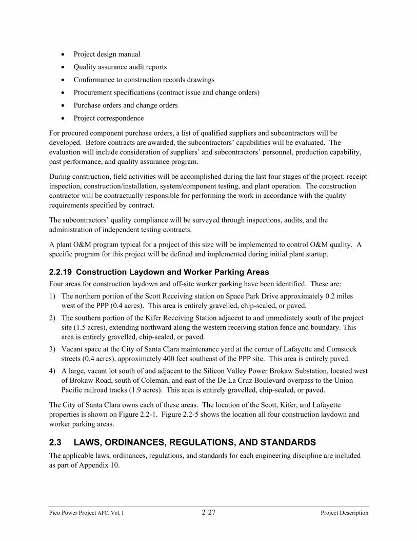
2.2.19 Construction Laydown and Worker Parking AreasFour areas for construction laydown and off-site worker parking have been identified. These are:1) The northern portion of the Scott Receiving station on Space Park Drive approximately 0.2 miles
west of the PPP (0.4 acres). This area is entirely gravelled, chip-sealed, or paved.2) The southern portion of the Kifer Receiving Station adjacent to and immediately south of the project
site (1.5 acres), extending northward along the western receiving station fence and boundary. Thisarea is entirely gravelled, chip-sealed, or paved.
3) Vacant space at the City of Santa Clara maintenance yard at the corner of Lafayette and Comstockstreets (0.4 acres), approximately 400 feet southeast of the PPP site. This area is entirely paved.
4) A large, vacant lot south of and adjacent to the Silicon Valley Power Brokaw Substation, located westof Brokaw Road, south of Coleman, and east of the De La Cruz Boulevard overpass to the UnionPacific railroad tracks (1.9 acres). This area is entirely gravelled, chip-sealed, or paved.
The City of Santa Clara owns each of these areas. The location of the Scott, Kifer, and Lafayetteproperties is shown on Figure 2.2-1. Figure 2.2-5 shows the location all four construction laydown andworker parking areas.
2.3 LAWS, ORDINANCES, REGULATIONS, AND STANDARDSThe applicable laws, ordinances, regulations, and standards for each engineering discipline are includedas part of Appendix 10.
Pico Power Project AFC, Vol. I 2-28 Project Description


![H1 2012 CC MASTER.ppt [Kompatibilitätsmodus]€¦ · + 12.2 % (+ 8.5 % cc) + 23.1% 33.4 42.9 + 28.7 % 41.6 51.2 195.8 237.4 + 21.2% (+ 17.3% cc) Order Intake ■Strong growth driven](https://img.pdfslide.us/doc/110x75/5f8a5be7d44e8d4747132bd5/h1-2012-cc-kompatibilittsmodus-122-85-cc-231-334-429-287.jpg)
![PRACTICE DIRECTION · In Manitoba, the expense of protracted family legal proceedings has created a barrier to ... and/or separation [QBR 70.25(1.1)] ... o Responsible for managing](https://img.pdfslide.us/doc/110x75/5e75db51d6616129ce2ebb59/practice-in-manitoba-the-expense-of-protracted-family-legal-proceedings-has-created.jpg)