Embed Size (px)
Citation preview
1
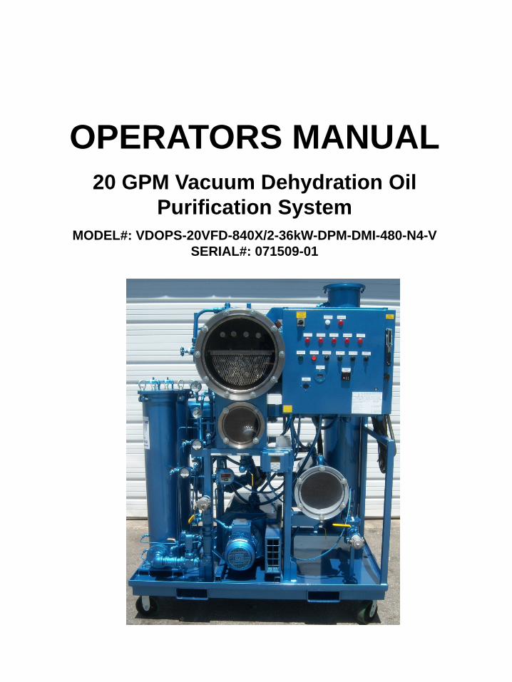
OPERATORS MANUAL20 GPM Vacuum Dehydration Oil
Purification SystemMODEL#: VDOPS-20VFD-840X/2-36kW-DPM-DMI-480-N4-V
SERIAL#: 071509-01
2
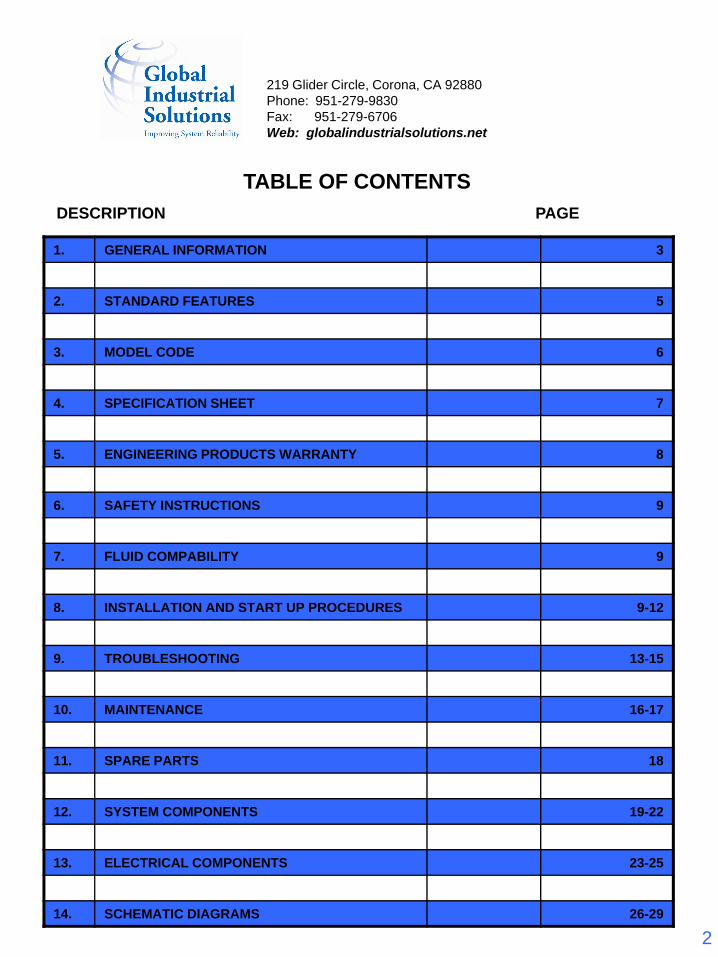
TABLE OF CONTENTSDESCRIPTION PAGE
1. GENERAL INFORMATION 3
2. STANDARD FEATURES 5
3. MODEL CODE 6
4. SPECIFICATION SHEET 7
5. ENGINEERING PRODUCTS WARRANTY 8
6. SAFETY INSTRUCTIONS 9
7. FLUID COMPABILITY 9
8. INSTALLATION AND START UP PROCEDURES 9-12
9. TROUBLESHOOTING 13-15
10. MAINTENANCE 16-17
11. SPARE PARTS 18
12. SYSTEM COMPONENTS 19-22
13. ELECTRICAL COMPONENTS 23-25
14. SCHEMATIC DIAGRAMS 26-29
219 Glider Circle, Corona, CA 92880Phone: 951-279-9830Fax: 951-279-6706Web: globalindustrialsolutions.net
3
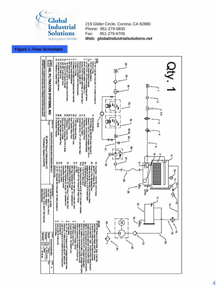
1. GENERAL INFORMATIONThe Vacuum Dehydration Oil Purification System is designed to remove free, emulsified and dissolved water, particulate and gaseous contamination from petroleum and synthetic based fluids. The water removal principle used is simple, reliable, and will dependably remove water well below the oil saturation point, even when tightly bound in an emulsion. Figure 1 on the next page shows schematically the systems operation. For the dehydration process, the fluid is first drawn into the heater of the system. It then flows through permanent dispersal media that is located inside the vacuum tower. The contaminated oil flows through the surfaces of this media where it is exposed to a vacuum, normally 22” Hg (559 mm Hg). The water and dissolved gases are boiled off and the fluid is dehydrated. An outlet pump removes the dry oil from the bottom of the vacuum chamber where it then passes through the filter housings and out the discharge of the system. For particulate removal, the system is typically equipped with a high efficiency filter element made from micro-glass media and rated Beta(c) > 1000 per ISO 16889, meaning that 99.9% of all particles of a given micron size are removed in a multi pass system.
219 Glider Circle, Corona, CA 92880Phone: 951-279-9830Fax: 951-279-6706Web: globalindustrialsolutions.net
4
Figure 1. Flow Schematic
219 Glider Circle, Corona, CA 92880Phone: 951-279-9830Fax: 951-279-6706Web: globalindustrialsolutions.net
5
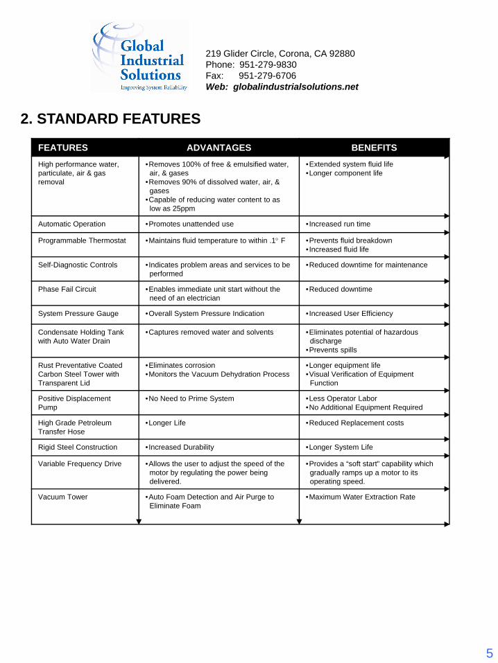
2. STANDARD FEATURES
FEATURES ADVANTAGES BENEFITSHigh performance water, particulate, air & gas removal
•Removes 100% of free & emulsified water,air, & gases
•Removes 90% of dissolved water, air, &gases
•Capable of reducing water content to aslow as 25ppm
•Extended system fluid life•Longer component life
Automatic Operation •Promotes unattended use •Increased run time
Programmable Thermostat •Maintains fluid temperature to within .1° F •Prevents fluid breakdown•Increased fluid life
Self-Diagnostic Controls •Indicates problem areas and services to beperformed
•Reduced downtime for maintenance
Phase Fail Circuit •Enables immediate unit start without theneed of an electrician
•Reduced downtime
System Pressure Gauge •Overall System Pressure Indication •Increased User Efficiency
Condensate Holding Tank with Auto Water Drain
•Captures removed water and solvents •Eliminates potential of hazardousdischarge
•Prevents spills
Rust Preventative Coated Carbon Steel Tower with Transparent Lid
•Eliminates corrosion•Monitors the Vacuum Dehydration Process
•Longer equipment life•Visual Verification of EquipmentFunction
Positive Displacement Pump
•No Need to Prime System •Less Operator Labor•No Additional Equipment Required
High Grade Petroleum Transfer Hose
•Longer Life •Reduced Replacement costs
Rigid Steel Construction •Increased Durability •Longer System Life
Variable Frequency Drive •Allows the user to adjust the speed of themotor by regulating the power beingdelivered.
•Provides a “soft start” capability whichgradually ramps up a motor to itsoperating speed.
Vacuum Tower •Auto Foam Detection and Air Purge toEliminate Foam
•Maximum Water Extraction Rate
219 Glider Circle, Corona, CA 92880Phone: 951-279-9830Fax: 951-279-6706Web: globalindustrialsolutions.net
6
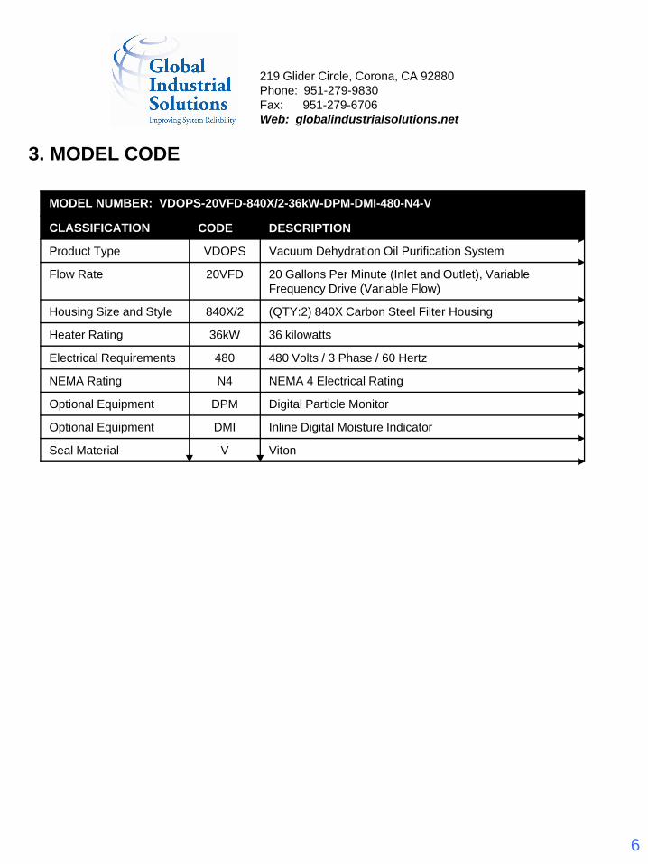
3. MODEL CODE
MODEL NUMBER: VDOPS-20VFD-840X/2-36kW-DPM-DMI-480-N4-V
CLASSIFICATION CODE DESCRIPTION
Product Type VDOPS Vacuum Dehydration Oil Purification System
Flow Rate 20VFD 20 Gallons Per Minute (Inlet and Outlet), Variable Frequency Drive (Variable Flow)
Housing Size and Style 840X/2 (QTY:2) 840X Carbon Steel Filter Housing
Heater Rating 36kW 36 kilowatts
Electrical Requirements 480 480 Volts / 3 Phase / 60 Hertz
NEMA Rating N4 NEMA 4 Electrical Rating
Optional Equipment DPM Digital Particle Monitor
Optional Equipment DMI Inline Digital Moisture Indicator
Seal Material V Viton
219 Glider Circle, Corona, CA 92880Phone: 951-279-9830Fax: 951-279-6706Web: globalindustrialsolutions.net
7
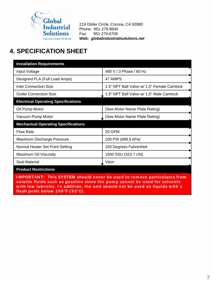
4. SPECIFICATION SHEET
Installation Requirements
Input Voltage 480 V / 3 Phase / 60 Hz
Designed FLA (Full Load Amps) 47 AMPS
Inlet Connection Size 1.5” NPT Ball Valve w/ 1.5” Female Camlock
Outlet Connection Size 1.5” NPT Ball Valve w/ 1.5” Male Camlock
Electrical Operating Specifications
Oil Pump Motor (See Motor Name Plate Rating)
Vacuum Pump Motor (See Motor Name Plate Rating)
Mechanical Operating Specifications
Flow Rate 20 GPM
Maximum Discharge Pressure 100 PSI (689.5 kPa)
Normal Heater Set Point Setting 150 Degrees Fahrenheit
Maximum Oil Viscosity 1500 SSU (323.7 cSt)
Seal Material Viton
Product Restrictions
IMPORTANT: This SYSTEM should never be used to remove particulates from volatile fluids such as gasoline since the pump cannot be used for solvents with low lubricity. In addition, the unit should not be used on liquids with a flash point below 200°F (93°C).
219 Glider Circle, Corona, CA 92880Phone: 951-279-9830Fax: 951-279-6706Web: globalindustrialsolutions.net
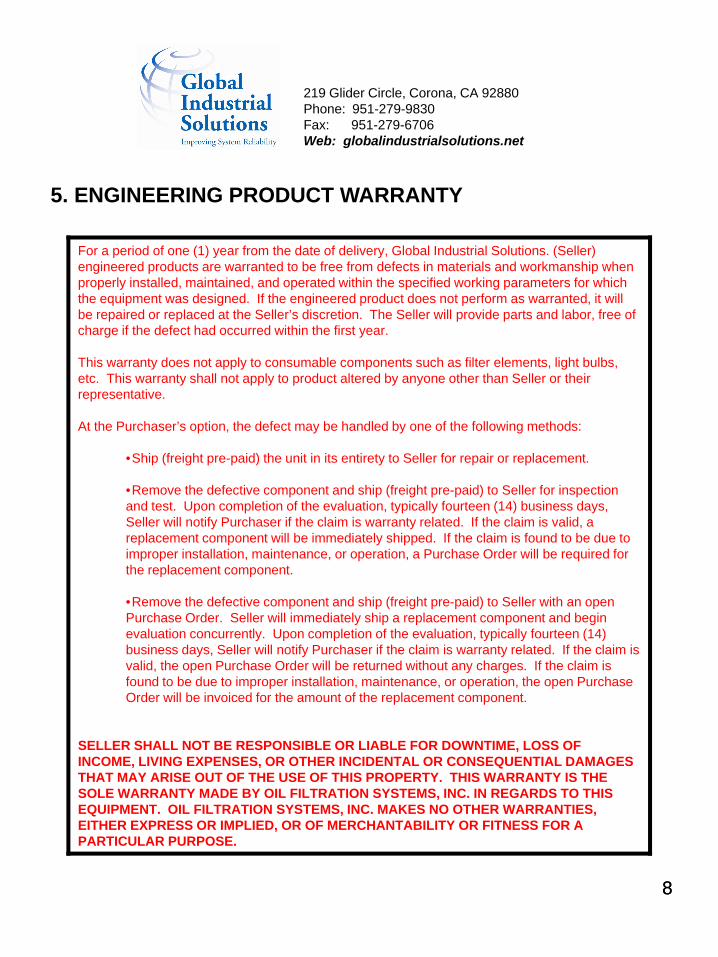
5. ENGINEERING PRODUCT WARRANTY
For a period of one (1) year from the date of delivery, Global Industrial Solutions. (Seller) engineered products are warranted to be free from defects in materials and workmanship when properly installed, maintained, and operated within the specified working parameters for which the equipment was designed. If the engineered product does not perform as warranted, it will be repaired or replaced at the Seller’s discretion. The Seller will provide parts and labor, free of charge if the defect had occurred within the first year.
This warranty does not apply to consumable components such as filter elements, light bulbs, etc. This warranty shall not apply to product altered by anyone other than Seller or their representative.
At the Purchaser’s option, the defect may be handled by one of the following methods:
•Ship (freight pre-paid) the unit in its entirety to Seller for repair or replacement.
•Remove the defective component and ship (freight pre-paid) to Seller for inspection and test. Upon completion of the evaluation, typically fourteen (14) business days, Seller will notify Purchaser if the claim is warranty related. If the claim is valid, a replacement component will be immediately shipped. If the claim is found to be due to improper installation, maintenance, or operation, a Purchase Order will be required for the replacement component.
•Remove the defective component and ship (freight pre-paid) to Seller with an open Purchase Order. Seller will immediately ship a replacement component and begin evaluation concurrently. Upon completion of the evaluation, typically fourteen (14) business days, Seller will notify Purchaser if the claim is warranty related. If the claim is valid, the open Purchase Order will be returned without any charges. If the claim is found to be due to improper installation, maintenance, or operation, the open Purchase Order will be invoiced for the amount of the replacement component.
SELLER SHALL NOT BE RESPONSIBLE OR LIABLE FOR DOWNTIME, LOSS OF INCOME, LIVING EXPENSES, OR OTHER INCIDENTAL OR CONSEQUENTIAL DAMAGES THAT MAY ARISE OUT OF THE USE OF THIS PROPERTY. THIS WARRANTY IS THE SOLE WARRANTY MADE BY OIL FILTRATION SYSTEMS, INC. IN REGARDS TO THIS EQUIPMENT. OIL FILTRATION SYSTEMS, INC. MAKES NO OTHER WARRANTIES, EITHER EXPRESS OR IMPLIED, OR OF MERCHANTABILITY OR FITNESS FOR A PARTICULAR PURPOSE.
88
219 Glider Circle, Corona, CA 92880Phone: 951-279-9830Fax: 951-279-6706Web: globalindustrialsolutions.net
9
6. SAFETY INSTRUCTIONSThis System has been examined and tested for safety. If there is any possibility that the oil beingpurified is contaminated with a solvent or materials which could be considered hazardous, either withtoxicant or flammable explosives, the purifier should not be used unless precautions are taken to ventthe vapors in a safe manner according to local, state, and federal codes and the flash point is above200°F (93°C). This caution is necessary to prevent the possibility of fire, explosion, or toxic injury topersons and property.
NOTE: Normal safety practices and common sense should always be exercised when operating this unit.
This system was manufactured to use 480V/3PH/60Hz input electrical power. The main power disconnect on the electrical panel door must be in the OFF position to gain access to the electrical panel. Supply power to the unit should be disconnected before the electrical panel door is opened. Only authorized and trained personnel should open the electrical cabinet to attempt service.
7. FLUID COMPABILITYDepending on the model number the following seals apply:
The process fluid must be compatible with Viton seal material. Viton is good in the temperature range of -15 F to +400F. It is generally recommended for lubricating, fuel and hydraulic oils. The unit may be ordered with other seals to provide compatibility with specialty fluids.
The process fluid must be compatible with Buna seal material. Buna N is generally recommended for petroleum, water, diesel and water glycol. This unit may be ordered with other seals to provide compatibility with specialty fluids. Buna N is good in the temperature range of -65°F to +250°F.
8. INSTALLATION AND START UP PROCEDURESUnpackingThis system is delivered with maximum protection during transportation and handling.
NOTE: All damage attributed to the handling and delivery of the unit must be recorded and brought to the attention of the shipper immediately.
This system has been thoroughly tested for a minimum run time required to ensure proper operation. Fluid used to test the unit is matched as closely as possible to that listed on the application sheet completed by the customer and supplied with the order. The unit has been thoroughly inspected for defects prior to the delivery. All connections, however, should be checked prior to operating this unit, vibration and/or rough handling during delivery could adversely affect component alignment and/or connection tightness.
219 Glider Circle, Corona, CA 92880Phone: 951-279-9830Fax: 951-279-6706Web: globalindustrialsolutions.net
10
Mechanical InstallationWith the system in place, connect the inlet and outlet hoses from the reservoir to the system. The inlet port has been sized to provide enough flow to operate the unit in the automatic mode using oil with a maximum viscosity of 1500 SSU (323.7 cSt). A hose diameter equal to inlet/outlet port size (see specification sheet) is required to provide adequate oil supply to this unit.
NOTE: Use of a smaller diameter line will restrict the flow and will adversely effect the automatic operation of the unit.
The inlet/outlet connections have been sized for maximum hose lengths of 35 feet. Use of longer hose lengths must be approved prior to installation. Use of a “quick disconnect” on the inlet line is not recommended. This can restrict flow to the unit in specific applications. Oil is drawn into the unit by vacuum created by the system and is capable of pulling oil with up to 8-ft. (2.4 m) of negative head. For applications that exceed this, please consult the factory.
Operating InstructionsConnect inlet and outlet hoses to the oil supply reservoir and system. Connect condensate sump discharge outlet to waste reservoir. Connect power supply cord to the electrical receptacle.
CAUTION: Supply Power Disconnect should be located within a line of sight to the
Power supply source.
Close all drain valves on the system.
Open all inlet and outlet valves on the system and the oil supply reservoir.
Supply power to the system. Turn the Main Power Disconnect to the ON position.
Check for phase failure. If the red light illuminates, phase failure exists. In that case, turn the Phase Reversal Switch to the opposite setting. Phase failure light should not be on.
Press the Start button.
Regulate the Pump Motor Speed Control (black dial) to the desired flow rate.
NOTE: The pump’s performance is regulated by the VFD’s motor frequency, and at 60 Hz, the pump will run at rated GPM. On the other hand, if the desired flow rate is half the rated GPM (for example), the knob should be set to 30 Hz.
Once the system is up and running, slowly open the air vent valves (on top of the filter housing) and bleed off the air in the vessels. Be sure that a container is placed under the vent valve while bleeding the air, as oil will come out after the air is purged.
After that, turn the heater switch to the ON position. The system is set at 150° F from the factory, but the temperature can be increased/decreased by pressing the scroll buttons on the Temperature Control. Normal maximum extraction rate is accomplished when the fluid is processed at a temperature between 140° – 160° F.
IMPORTANT: It is important to never turn off the discharge pump while the heater is energized. This can cause the heater to overheat.
219 Glider Circle, Corona, CA 92880Phone: 951-279-9830Fax: 951-279-6706Web: globalindustrialsolutions.net
11
Next, observe the Vacuum Gauge pressure. Normal indication should be between18-26” Hg for the Vacuum Pump. If not, adjust the vacuum by opening or closing the Vacuum Regulator Valve located just below the Air Inlet Filter. This adjustment is gradual and does not respond quickly so there will be a 3-5 second delay in results when the adjustment is made.
WARNING: Do not operate the Vacuum Pump below 26” Hg. 18” to 26” Hg vacuum pressure is the ultimate vacuum for continuous operation of the Pump.
The system is now fully functioning. Normal discharge operating pressure is 5 – 20 PSI. However, with restricted or long discharge lines the pressure can be higher. The pump is set from the factory to relieve at 100 PSI.
It is not recommended that you run the system at less than 30 HZ with greater than 30 PSI discharge pressure for extended periods of time. This can damage the VFD or motor on the system. A prime indicator of this operational default is error code EO24 on the VFD
When an alarm occurs, check the specific alarm indicator and solve it by using the Troubleshooting Section of this manual. After fixing the problem, press the Stop/Reset button and then press the Start button to run the system again.
To stop the system, close the inlet valve and allow it to run for approximately 30 seconds. The system oil will be returned to the reservoir. Then simply press the Stop/Reset button.
Close all valves from the reservoir and on the system.
Turn the Main Power Disconnect to the OFF position.
Auto Water Drain (Optional)Located on the back side of the water sump are two electric switches, one on the top and the other on the bottom. When the system is in operation, water will begin to fill the sump. Once the water reaches the top electric switch, the auto water drain operation will begin. First, the vacuum isolation ball valve closes to keep the vacuum inside the main tower. Next, the system shuts down. The vent valve and drain valve then open simultaneously. The water then begins to drain. Once the water level in the sump falls below the bottom electric switch, the vent valve and drain valve will close. Finally, the system will start back-up and open the vacuum isolation valve. This cycle will repeat every time the water sump is filled. If there is a problem with the auto water drain, and the sump fills, the system will shut down after two minutes.
Vacuum Tower Bypass (Optional)This operation is located on the back of system between the discharge from the heaters and the intake of the vacuum tower. The main function of this option is to isolate the flow from the heater pass the tower and through the discharge line back to the reservoir, eliminating the dehydration process. While the dehydration may be turned off, your heaters will still be engaged allowing the oil to heat up to the required temp. To enable this process you will need to close the inlet valve going into the tower, open the Tower Bypass valve and close the valve from the tower to the pump. After you open and close the proper valves, turn the Bypass Switch (VDOP Bypass Switch) to the ON position and adjust the motor speed accordingly to the situation at hand.
219 Glider Circle, Corona, CA 92880Phone: 951-279-9830Fax: 951-279-6706Web: globalindustrialsolutions.net
12
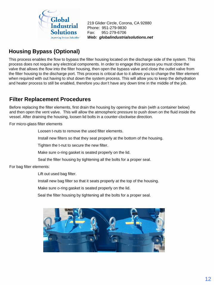
Filter Replacement ProceduresBefore replacing the filter elements, first drain the housing by opening the drain (with a container below) and then open the vent valve. This will allow the atmospheric pressure to push down on the fluid inside the vessel. After draining the housing, loosen lid bolts in a counter-clockwise direction.
For micro-glass filter elements
Loosen t-nuts to remove the used filter elements.
Install new filters so that they seat properly at the bottom of the housing.
Tighten the t-nut to secure the new filter.
Make sure o-ring gasket is seated properly on the lid.
Seal the filter housing by tightening all the bolts for a proper seal.
For bag filter elements:
Lift out used bag filter.
Install new bag filter so that it seats properly at the top of the housing.
Make sure o-ring gasket is seated properly on the lid.
Seal the filter housing by tightening all the bolts for a proper seal.
Housing Bypass (Optional)This process enables the flow to bypass the filter housing located on the discharge side of the system. This process does not require any electrical components. In order to engage this process you must close the valve that allows the flow into the filter housing, then open the bypass valve and close the outlet valve from the filter housing to the discharge port. This process is critical due to it allows you to change the filter element when required with out having to shut down the system process. This will allow you to keep the dehydration and heater process to still be enabled, therefore you don’t have any down time in the middle of the job.
219 Glider Circle, Corona, CA 92880Phone: 951-279-9830Fax: 951-279-6706Web: globalindustrialsolutions.net
13
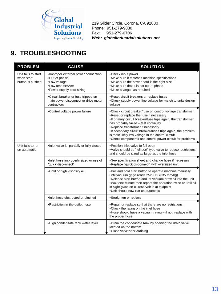
9. TROUBLESHOOTING
PROBLEM CAUSE SOLUTION
Unit fails to start when start button is pushed
•Improper external power connection•Out of phase•Low voltage•Low amp service•Power supply cord sizing
•Check input power•Make sure it matches machine specifications•Make sure the power cord is the right size•Make sure that it is not out of phase•Make changes as required
•Circuit breaker or fuse tripped on main power disconnect or drive motor contractors
•Reset circuit breakers or replace fuses•Check supply power line voltage for match to units design voltage
•Control voltage power failure •Check circuit breaker/fuse on control voltage transformer•Reset or replace the fuse if necessary•If primary circuit breaker/fuse trips again, the transformer has probably failed – test continuity•Replace transformer if necessary•If secondary circuit breaker/fuses trips again, the problem is most likely low voltage in the control circuit•Check components and control power circuit for problems
Unit fails to run on automatic
•Inlet valve is partially or fully closed •Position inlet valve to full open•Valve should be “full port” type valve to reduce restrictions and should be sized as large as the inlet hose
•Inlet hose improperly sized or use of “quick disconnect”
•See specification sheet and change hose if necessary•Replace “quick disconnect” with oversized unit
•Cold or high viscosity oil •Pull and hold start button to operate machine manually until vacuum gage reads 25in/HG (635 mm/hg)•Release start button and let vacuum draw oil into the unit•Wait one minute then repeat the operation twice or until oil in sight glass on oil reservoir is at midpoint•Unit should now run on automatic
•Inlet hose obstructed or pinched •Straighten or replace
•Restriction in the outlet hose •Repair or replace so that there are no restrictions•Check the rating on the inlet hose•Hose should have a vacuum rating – if not, replace with the proper hose
•High condensate tank water level •Drain the condensate tank by opening the drain valve located on the bottom•Close valve after draining
219 Glider Circle, Corona, CA 92880Phone: 951-279-9830Fax: 951-279-6706Web: globalindustrialsolutions.net
14
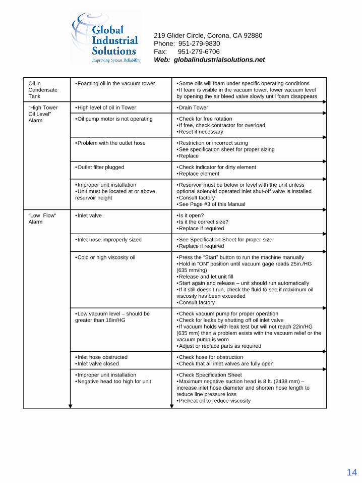
Oil in Condensate Tank
•Foaming oil in the vacuum tower •Some oils will foam under specific operating conditions•If foam is visible in the vacuum tower, lower vacuum level by opening the air bleed valve slowly until foam disappears
“High Tower Oil Level” Alarm
•High level of oil in Tower •Drain Tower
•Oil pump motor is not operating •Check for free rotation•If free, check contractor for overload•Reset if necessary
•Problem with the outlet hose •Restriction or incorrect sizing•See specification sheet for proper sizing•Replace
•Outlet filter plugged •Check indicator for dirty element•Replace element
•Improper unit installation•Unit must be located at or above reservoir height
•Reservoir must be below or level with the unit unless optional solenoid operated inlet shut-off valve is installed•Consult factory•See Page #3 of this Manual
“Low Flow“ Alarm
•Inlet valve •Is it open?•Is it the correct size?•Replace if required
•Inlet hose improperly sized •See Specification Sheet for proper size•Replace if required
•Cold or high viscosity oil •Press the “Start” button to run the machine manually•Hold in “ON” position until vacuum gage reads 25in./HG (635 mm/hg)•Release and let unit fill•Start again and release – unit should run automatically•If it still doesn’t run, check the fluid to see if maximum oil viscosity has been exceeded•Consult factory
•Low vacuum level – should be greater than 18in/HG
•Check vacuum pump for proper operation•Check for leaks by shutting off oil inlet valve•If vacuum holds with leak test but will not reach 22in/HG (635 mm) then a problem exists with the vacuum relief or the vacuum pump is worn•Adjust or replace parts as required
•Inlet hose obstructed•Inlet valve closed
•Check hose for obstruction•Check that all inlet valves are fully open
•Improper unit installation•Negative head too high for unit
•Check Specification Sheet•Maximum negative suction head is 8 ft. (2438 mm) –increase inlet hose diameter and shorten hose length to reduce line pressure loss•Preheat oil to reduce viscosity
219 Glider Circle, Corona, CA 92880Phone: 951-279-9830Fax: 951-279-6706Web: globalindustrialsolutions.net
15
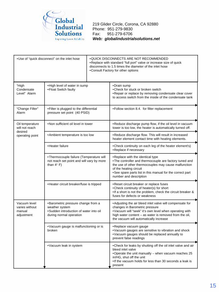
“High Condensate Level” Alarm
•High level of water in sump•Float Switch faulty
•Drain sump•Check for stuck or broken switch•Repair or replace by removing condensate clear cover to access switch from the inside of the condensate tank
“Change Filter”Alarm
•Filter is plugged to the differential pressure set point (40 PSID)
•Follow section 8.4. for filter replacement
Oil temperature will not reach desired operating point
•Non sufficient oil level in tower •Reduce discharge pump flow, if the oil level in vacuum tower is too low, the heater is automatically turned off.
•Ambient temperature is too low •Reduce discharge flow. This will result in increased heater element contact time with heating elements.
•Heater failure •Check continuity on each leg of the heater element's)•Replace if necessary
•Thermocouple failure (Temperature will not reach set point and will vary by more than 4° F)
•Replace with the identical type•The controller and thermocouple are factory tuned and the use of other thermocouples may cause malfunction of the heating circuit•See spare parts list in this manual for the correct part number and description
•Heater circuit breaker/fuse is tripped •Reset circuit breaker or replace fuses•Check continuity of heater(s) for short•If a short is not the problem, check the circuit breaker & fuses for defects or weakness
Vacuum level varies without manual adjustment
•Barometric pressure change from a weather system•Sudden introduction of water into oil during normal operation
•Adjusting the air bleed inlet valve will compensate for changes in Barometric pressure•Vacuum will “seek” it’s own level when operating with high water content – as water is removed from the oil, the vacuum will automatically increase
•Vacuum gauge is malfunctioning or is broken
•Replace vacuum gauge•Vacuum gauges are sensitive to vibration and shock•Vacuum gauges should be replaced annually to prevent false readings
•Vacuum leak in system •Check for leaks by shutting off the oil inlet valve and air bleed inlet valve•Operate the unit manually – when vacuum reaches 25 in/HG, shut off the unit•If the vacuum holds for less than 30 seconds a leak is present
•Use of “quick disconnect” on the inlet hose •QUICK DISCONNECTS ARE NOT RECOMMENDED•Replace with standard “full port” valve or increase size of quick disconnects to 1.5 times the diameter of the inlet hose•Consult Factory for other options
219 Glider Circle, Corona, CA 92880Phone: 951-279-9830Fax: 951-279-6706Web: globalindustrialsolutions.net
16
10. MAINTENANCE
Vacuum Chamber Internal Dispersion MediaThe dispersal media function is to maximize the surface area of the oil exposed to the vacuum by creating a thin oil film as the oil passes over the media. This process makes the water removal process much more efficient. The internal dispersion media is stainless steel and never needs to be changed.
Oil Filter ElementThe outlet filter is equipped with a differential pressure indicator to alert the user when the element is ready to be changed. This indicator is calibrated to 30-40 PSID at which time the system will automatically shut down. Element change frequency can and will vary with every application and cannot be predicted effectively. However, the filter has be over sized by approximately six (6) times rated flow to maximize the life of the element under normal conditions.
It is suggested that the element be changed every six (6) months if no indication is shown during that time. The filter media can become fatigued and fail due to flow surges, heat, water, and pressure after continuous operation over a long period of time.
Vacuum Tower Air Inlet FilterMetered outside air used to control the vacuum pressure inside the vacuum chamber, this air is cleaned using a filter/breather to remove particulates form the air as it enters the vacuum chamber. The element can be plugged within a very short period of time if larger amounts of air-borne contaminates are present. Under normal operating conditions and continuous operation, the air breather element will last approx 3-5 months before change out.
Vacuum Pump Coalescing FilterThe vacuum pump uses a coalescing outlet filter element to filter the exhaust air leaving the vacuum pump. The element is a cloth type with exterior metal canister attached to the discharge of the vacuum pump. To replace this element, expand and slide down the two spring retainers which are located on the outside of the coalescing element. Do the reverse process for installation of new cloth element.
219 Glider Circle, Corona, CA 92880Phone: 951-279-9830Fax: 951-279-6706Web: globalindustrialsolutions.net
17
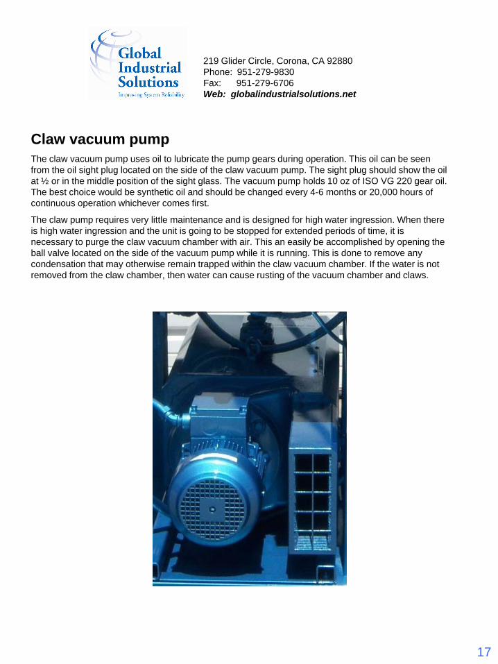
Claw vacuum pumpThe claw vacuum pump uses oil to lubricate the pump gears during operation. This oil can be seen from the oil sight plug located on the side of the claw vacuum pump. The sight plug should show the oil at ½ or in the middle position of the sight glass. The vacuum pump holds 10 oz of ISO VG 220 gear oil. The best choice would be synthetic oil and should be changed every 4-6 months or 20,000 hours of continuous operation whichever comes first.
The claw pump requires very little maintenance and is designed for high water ingression. When there is high water ingression and the unit is going to be stopped for extended periods of time, it is necessary to purge the claw vacuum chamber with air. This an easily be accomplished by opening the ball valve located on the side of the vacuum pump while it is running. This is done to remove any condensation that may otherwise remain trapped within the claw vacuum chamber. If the water is not removed from the claw chamber, then water can cause rusting of the vacuum chamber and claws.
219 Glider Circle, Corona, CA 92880Phone: 951-279-9830Fax: 951-279-6706Web: globalindustrialsolutions.net
18
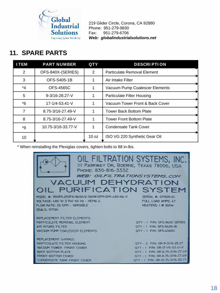
11. SPARE PARTSITEM PART NUMBER QTY DESCRIPTION
2 OFS-840X-(SERIES) 2 Particulate Removal Element
3 OFS-S405-1B 1 Air Intake Filter
*4 OFS-4565C 1 Vacuum Pump Coalescer Elements
5 9-3/16-28.27-V 1 Particulate Filter Housing
*6 17-1/4-53.41-V 1 Vacuum Tower Front & Back Cover
7 8.75-3/16-27.49-V 1 Tower Back Bottom Plate
8 8.75-3/16-27.49-V 1 Tower Front Bottom Plate
*9 10.75-3/16-33.77-V 1 Condensate Tank Cover
10 10 oz ISO VG 220 Synthetic Gear Oil
* When reinstalling the Plexiglas covers, tighten bolts to 88 in-lbs.
219 Glider Circle, Corona, CA 92880Phone: 951-279-9830Fax: 951-279-6706Web: globalindustrialsolutions.net
19
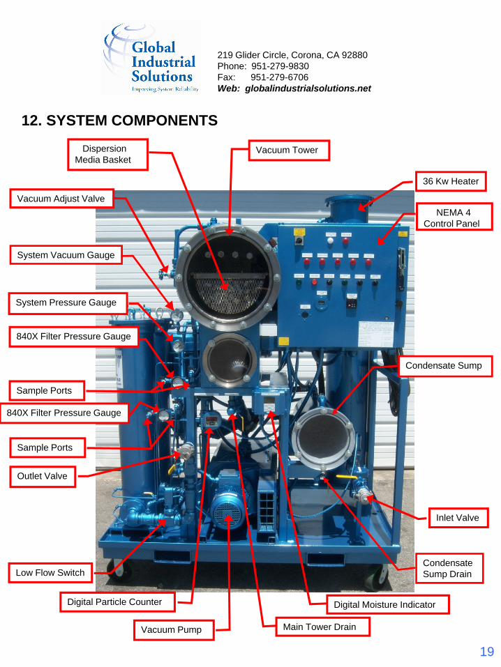
12. SYSTEM COMPONENTS
Inlet Valve
Dispersion Media Basket
NEMA 4 Control Panel
Vacuum Pump
Outlet Valve
Vacuum Tower
Condensate Sump
Main Tower Drain
Sample Ports
840X Filter Pressure Gauge
System Pressure Gauge
System Vacuum Gauge
Vacuum Adjust Valve
Sample Ports
840X Filter Pressure Gauge
Low Flow Switch
Digital Particle Counter Digital Moisture Indicator
36 Kw Heater
Condensate Sump Drain
219 Glider Circle, Corona, CA 92880Phone: 951-279-9830Fax: 951-279-6706Web: globalindustrialsolutions.net
20
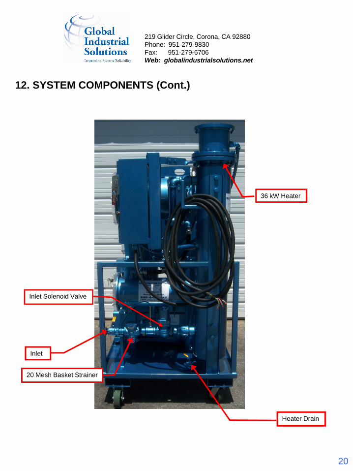
12. SYSTEM COMPONENTS (Cont.)
Heater Drain
Inlet Solenoid Valve
20 Mesh Basket Strainer
Inlet
36 kW Heater
219 Glider Circle, Corona, CA 92880Phone: 951-279-9830Fax: 951-279-6706Web: globalindustrialsolutions.net
21
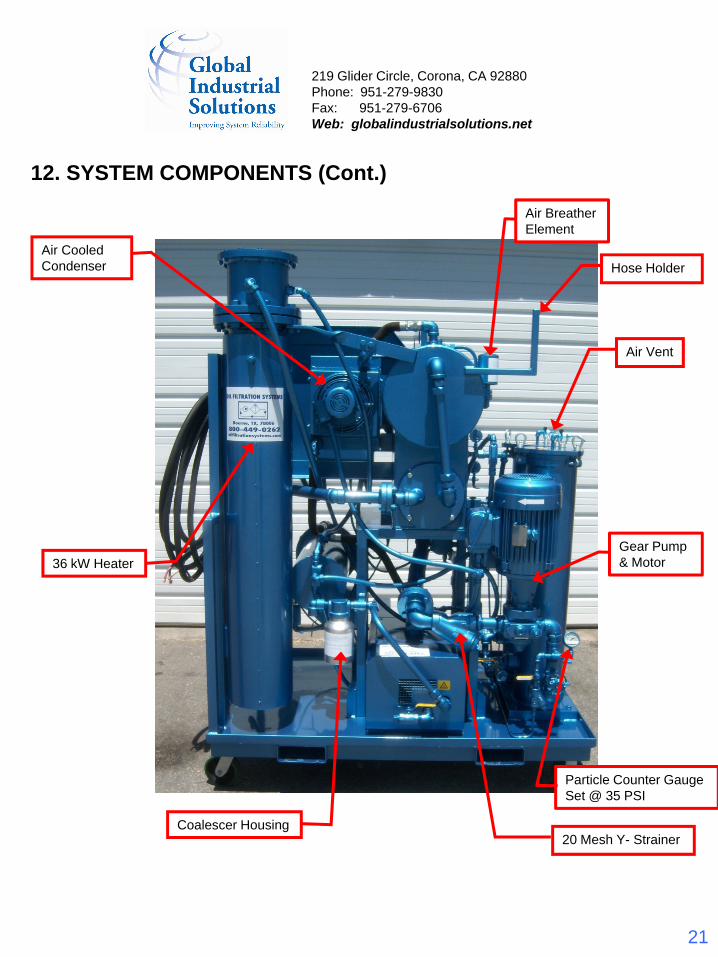
12. SYSTEM COMPONENTS (Cont.)
Air Cooled Condenser
Coalescer Housing20 Mesh Y- Strainer
36 kW Heater
Air Breather Element
Gear Pump & Motor
Particle Counter Gauge Set @ 35 PSI
Air Vent
Hose Holder
219 Glider Circle, Corona, CA 92880Phone: 951-279-9830Fax: 951-279-6706Web: globalindustrialsolutions.net
22
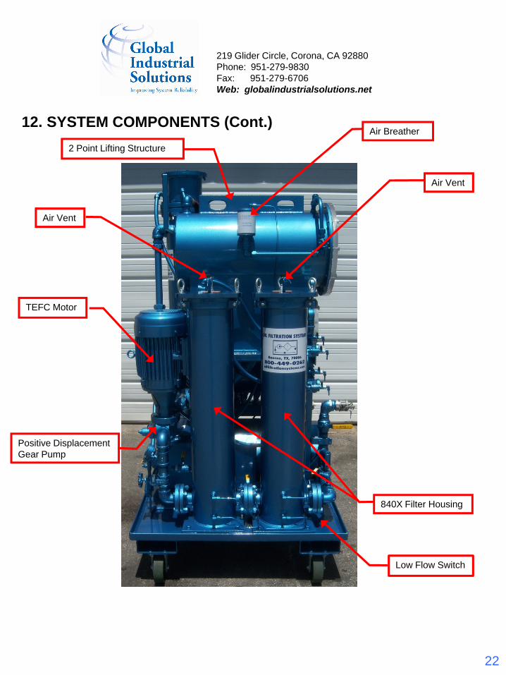
12. SYSTEM COMPONENTS (Cont.)
840X Filter Housing
TEFC Motor
Low Flow Switch
Positive Displacement Gear Pump
Air Vent
Air Vent
Air Breather
2 Point Lifting Structure
219 Glider Circle, Corona, CA 92880Phone: 951-279-9830Fax: 951-279-6706Web: globalindustrialsolutions.net
23
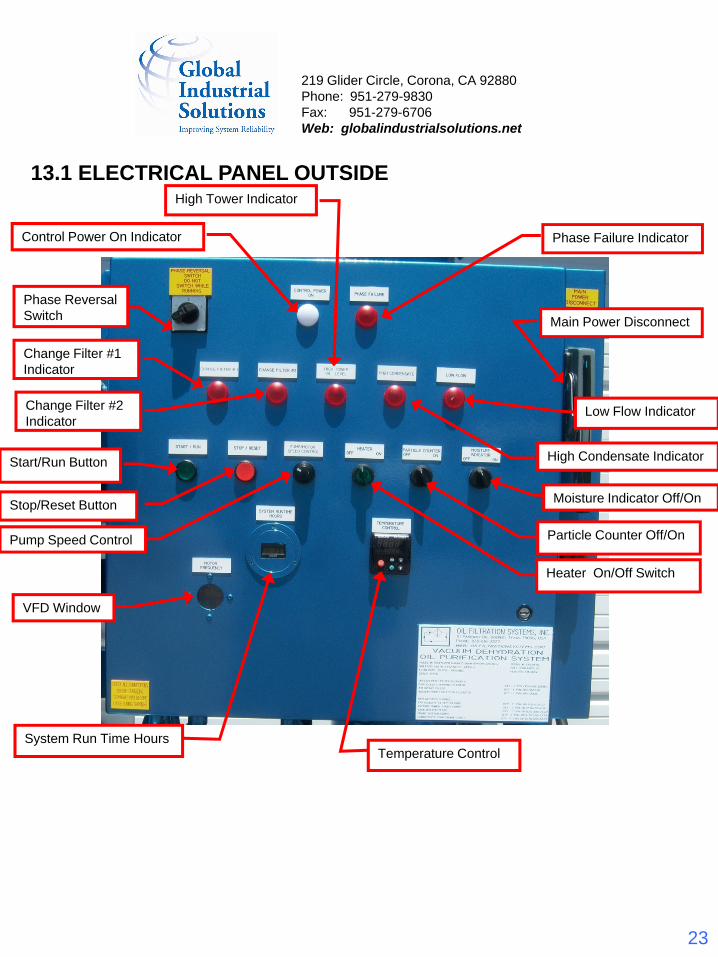
13.1 ELECTRICAL PANEL OUTSIDE
Change Filter #1 Indicator
High Tower Indicator
High Condensate Indicator
Temperature Control
Heater On/Off Switch
Phase Reversal Switch Main Power Disconnect
Control Power On Indicator
System Run Time Hours
Pump Speed Control
Start/Run Button
VFD Window
Stop/Reset Button
Low Flow Indicator
Phase Failure Indicator
Particle Counter Off/On
Moisture Indicator Off/On
Change Filter #2 Indicator
219 Glider Circle, Corona, CA 92880Phone: 951-279-9830Fax: 951-279-6706Web: globalindustrialsolutions.net
24
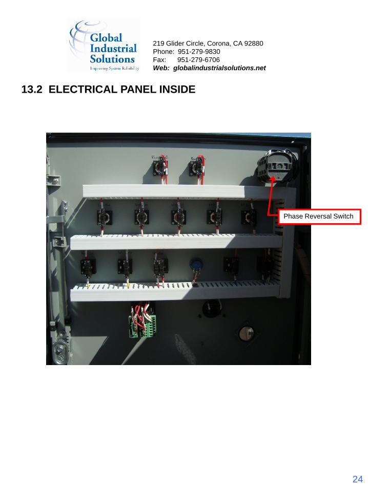
13.2 ELECTRICAL PANEL INSIDE
Phase Reversal Switch
219 Glider Circle, Corona, CA 92880Phone: 951-279-9830Fax: 951-279-6706Web: globalindustrialsolutions.net
25
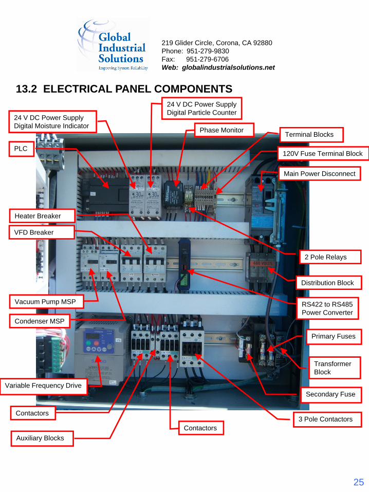
13.2 ELECTRICAL PANEL COMPONENTS
PLC
Distribution Block
Main Power Disconnect
Terminal Blocks
24 V DC Power Supply Digital Moisture Indicator
Auxiliary Blocks
Variable Frequency Drive
Primary Fuses
3 Pole Contactors
2 Pole Relays
Contactors
Condenser MSP
Vacuum Pump MSP
Secondary Fuse
Transformer Block
Phase Monitor
Heater Breaker
VFD Breaker
24 V DC Power Supply Digital Particle Counter
120V Fuse Terminal Block
Contactors
RS422 to RS485 Power Converter
219 Glider Circle, Corona, CA 92880Phone: 951-279-9830Fax: 951-279-6706Web: globalindustrialsolutions.net
26
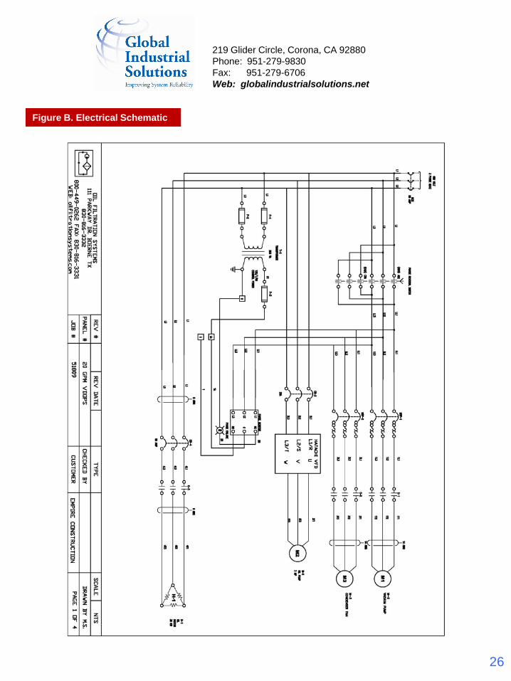
Figure B. Electrical Schematic
219 Glider Circle, Corona, CA 92880Phone: 951-279-9830Fax: 951-279-6706Web: globalindustrialsolutions.net
27
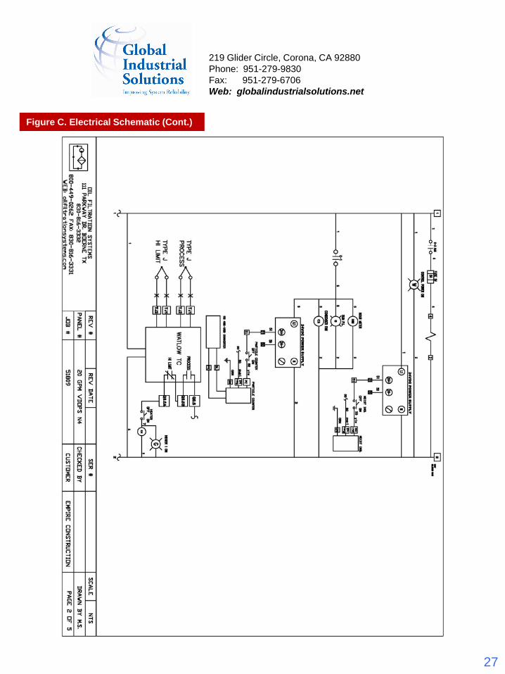
Figure C. Electrical Schematic (Cont.)
219 Glider Circle, Corona, CA 92880Phone: 951-279-9830Fax: 951-279-6706Web: globalindustrialsolutions.net
28
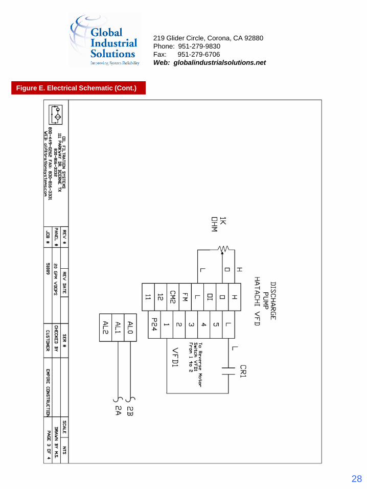
Figure E. Electrical Schematic (Cont.)
219 Glider Circle, Corona, CA 92880Phone: 951-279-9830Fax: 951-279-6706Web: globalindustrialsolutions.net
29
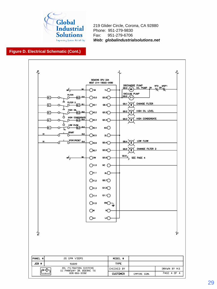
Figure D. Electrical Schematic (Cont.)
219 Glider Circle, Corona, CA 92880Phone: 951-279-9830Fax: 951-279-6706Web: globalindustrialsolutions.net