Embed Size (px)
Citation preview
300 Summers Street, Suite 1200, Charleston, WV 25301-1630
Phone: 304/342-2151 Fax: 304/342-2197 Email: [email protected]
20 April 2011 ADDENDUM #1 (via facsimile – total of 25 pages) Headquarters Building Blue Ridge Community & Technical College Martinsburg, West Virginia RFB #11169
The following items are clarifications and/or changes to the scope of the work and shall be included in the contract price.
Specifications Item #1 General
A. Bid Date has been extended to Thursday, April 28, 2011 at 3:00 PM, Eastern Time. Bids are to be delivered to:
Chief Procurement Officer RFB 11169
West Virginia Council for Community and Technical College Education 1018 Kanawha Boulevard, East, Suite 700 Charleston, WV 25301
It shall be the bidder’s responsibility to determine their method of transmittal such that their bids will arrive in the Owner’s office prior to the scheduled bid opening. Proposals received by the Owner after the scheduled opening will be left unopened. Fax and electronically transmitted Bids will not be accepted. All proposals must be enclosed in sealed envelopes bearing the name and address of the bidder and must be marked: “HEADQUARTERS BUILDING – BLUE RIDGE COMMUNITY & TECHNICAL COLLEGE”
B. General Contractors are required to apply for a building permit with the Berkeley
County Planning Commission (304) 264-1966. Building permit cost is $250 plus $0.27 per square foot. Actual building square footage is 55,721 SF. It is recommended that all Bidders contact the Berkeley County Planning Commission to verify permitting, licensure, and tax requirements.
Item #2 Section 01210 – Allowances A. Refer to Schedule of Allowances and add the following:
I. Allowance No. 9: DEP Permit - $1,170.00. This allowance includes the review
fee to be paid to WVDEP. The application and drawings have been forwarded to the WVDEP. The cost of this allowance to be included in the base bid proposal.

4/20/11 Addendum #1 – Blue Ridge Community & Technical College Page 2 of 8
Item #3 Section 01230 – Alternates A. Clarification: In reference to Alternate No 1, bidder are to assume an anticipated
Notice to Proceed date would be on or before May 15, 2011. B. Refer to Schedule of Alternates, Alternate No. 8 delete reference to Alternate No.4 and
note that the Access Drive is Alternate No. 5. Item #4 Section 01400 – Quality Requirements A. Clarification: All quality control testing is to be provided by Contractor.
B. Refer to Article 3.1 and add ECS Mid-Atlantic, LLC as an acceptable testing agency. Item #5 Section 02300 – Earthwork A. Refer to Article 1.5 – Submittals and add the following:
D. Blasting plan approved by authorities having jurisdiction.
E. Seismic survey report from seismic survey agency. B. Refer to Article 1.6 – Quality Assurance and add the following:
C. Blasting: Comply with applicable requirements in NFPA 495, "Explosive Materials Code," and prepare a blasting plan reporting the following:
1. Types of explosive and sizes of charge to be used in each area of rock removal, types of blasting mats, sequence of blasting operations, and procedures that will prevent damage to site improvements and structures on Project site and adjacent properties.
2. Seismographic monitoring during blasting operations.
D. Seismic Survey Agency: An independent testing agency, acceptable to authorities having jurisdiction, experienced in seismic surveys and blasting procedures to perform the following services:
1. Report types of explosive and sizes of charge to be used in each area of rock removal, types of blasting mats, sequence of blasting operations, and procedures that will prevent damage to site improvements and structures on Project site and adjacent properties.
2. Seismographic monitoring during blasting operations.”
C. Refer to the end of Part 3 and add the following:
3.21 EXPLOSIVES
A. Explosives: Obtain written permission from authorities having jurisdiction before bringing explosives to Project site or using explosives on Project site.
1. Perform blasting without damaging adjacent structures, property, or site improvements.
2. Perform blasting without weakening the bearing capacity of rock subgrade and with the least-practicable disturbance to rock to remain.

4/20/11 Addendum #1 – Blue Ridge Community & Technical College Page 3 of 8
Item #6 Section 02870 – Site Furnishings A. Note that site furnishings are indicated on the civil drawings and on the roof plan at the
vegetative roof terrace. Item #7 Section 05120 – Structural Steel Framing A. Refer to Article 1.7 – Quality Assurance and delete paragraph B and revise paragraph
A to read as follows: “Fabricator Qualifications: A qualified fabricator that participates in the AISC Quality Certification Program.”
Item #8 Section 07272 – Fluid-Applied Membrane Air Barriers
A. Refer to Article 2.1 – Fluid-Applied Membrane Air Barrier and add Enershield-HP; BASF Wall Systems as an acceptable product, subject to compliance with project requirements.
Item #9 Section 07312 – Simulated Slate Shingles A. Refer to Article 2.1 and add Inspire Roofing Products, and DaVinci Roofscapes as
acceptable manufacturers, subject to compliance with the project requirements. Item #10 Section 07531 – EPDM Membrane Roofing
A. Refer to Article 2.3 and add the following:
C. Non-reinforced, 60 mil thick, polyepichlorohydrin (ECO/CO) roofing membrane. Provide related sealants and accessories as required by manufacturer to achieve specified warranty.
1. Membrane to be installed within 5 feet of all exhaust fans and chiller unit. 2. Basis-of-Design- Product: Carlisle Sure-Seal Polyepichlorohydrin (ECO/CO)
60 mil, roofing membrane. Item #11 Section 07710 – Manufactured Roof Specialties A. Refer to Article 2.1 and add Architectural Products Co. as an acceptable manufacturer
for both formed-aluminum copings and formed-aluminum fascia, scuppers, gutters, and downspouts, subject to compliance with project requirements.
Item #12 Section 08110 – Steel Doors and Frames
A. Refer to Article 2.1 and add MPI Group as an acceptable manufacturer, subject to compliance with the project requirements.
Item #13 Section 08211 – Flush Wood Doors
A. Refer to Article 2.1 and add Oshkosh Architectural Door Company as an acceptable manufacturer, subject to compliance with the project requirements.

4/20/11 Addendum #1 – Blue Ridge Community & Technical College Page 4 of 8
Item #14 Section 08800 – Glazing A. Refer to Article 2.11 – Insulating-Glass Types and note that Low-E coating is to be on
the third surface. Glazing manufacturer to confirm the appropriate surface for Low-E coating and glass construction per delegated-design requirements.
Item #15 Section 09260 – Gypsum Board Assemblies A. Refer to Article 2.4 – Interior Gypsum Board and delete paragraphs “D (Foil-Backed
Gypsum Board) and E (Abuse-Resistant Gypsum Board)” in their entirety. Item #16 Section 10100 – Visual Display Boards A. Refer to Article 2.1 – Manufacturers and add American Visual Display Products as an
acceptable manufacturer, subject to compliance with project requirements. Item #17 Section 10200 – Louvers and Vents
A. Refer to Article 2.3 and add Arrow United Industries as an acceptable manufacturer, subject to compliance with the project requirements.
Item #18 Section 10651 – Operable Panel Partitions A. Refer to Article 2.1 – Products and Manufacturers and add Moderco as an acceptable
manufacturer, subject to compliance with project requirements. B. Refer to Article 2.5 – Finish Facing and note that the supplier is responsible for
providing the fabric to the operable panel manufacturer. Item #19 Section 11610 – Laboratory Fume Hoods
A. Refer to Article 2.1 and add BMC as an acceptable manufacturer, subject to compliance with the project requirements.
B. Refer to Article 2.4, paragraph A and delete reference to restricted bypass. The hood
is to be non-restricted by-pass, constant volume allowing same air flow rate whether the sash is fully open or closed. The hood shall be equipped at 100 FPM, the exhaust CFM is 975.
C. Refer to Article 2.4, paragraph D and delete quantity reference and replace with
“Quantity as indicated on Drawings.” D. Refer to Article 2.5, paragraph C and note that the hood shall be equipped to provide
1218 CFM and 2.2 inches negative air pressure at the hood connection outlet. E. Refer to Article 2.5 – Laminar Flow Biological Safety Hood and add the following
Paragraph:
D. Safety Monitor/Alarm System: Where shown or specified provide Safety Monitor/Alarm System which monitors face velocity and provides audible and visual alarm if face velocity drops below safe levels. As the internal hood pressure changes as the sash opening is closed and opened, the flow passing over the thermistor is calibrated to a face velocity which is displayed on the front of the monitor.

4/20/11 Addendum #1 – Blue Ridge Community & Technical College Page 5 of 8
1. Hood to have two pole single throw switch (DPST) for fan and alarm panel control.
2. Hood to have air flow alarm panel that has a binary alarm contact to connect to the building DDC system to the hood alarm panel.
3. Hood alarm panel to have a plug in connection and a switched receptacle on the top of the hood. One set of poles on the fan switch will turn the hood alarm panel on or off and the other set will turn the exhaust fan on or off.
Item #20 Section 12354 – Manufactured Plastic-Laminate-Faced Casework A. Delete Article 1.8 in its entirety. B. Refer to Article 2.2 – Casework, General: 1) Under Paragraph A, delete subparagraph 2 in its entirety. 2) Delete paragraphs B and D in their entirety. Drawings Item #21 General Notes: A. Projection screens shown on the floor plans and the enlarged plan designated as
“PW88” should read “PW68” B. Refer to enlarged plans for items not indicated on the floor plans (projection screens,
markerboards, etc.) Item #22 C1.01 – Onsite Clring & Initl. Erosion Cont. Plan A. The existing structure located to the east of the entry drive connection to Route 45 is to
be completely removed. B. Add the following to the Topsoil Handling Notes: “10. All disturbed areas within the
noted limits of clearing and grading except (1) the two stormwater management facilities shown shaded, (2) the sanitary force main from the pump station to the east property line, (3) the water main extension from the fire pump house to the east property line, and (4) the access drive from the fire pump house to the sanitary pump station are to be backfilled with 6” of topsoil for grass seeding. This 6” topsoil section is to consist of a base of 4” of topsoil from the treatment cells and the top 2” is to consist of offsite topsoil furnished and installed by the contractor. After removing onsite topsoil from the treatment cells, the remaining topsoil in the cells are to be wetted and seeded again as noted in note #6. See specification section 02940 for additional information on preparation for planting lawns. The 5 areas noted above do not require the placement of topsoil but these areas are to be fine graded; all roots, rocks, clogs, etc removed from the surface; and seeded and mulched in accordance with specification section 02940.”
C. Excess, clean excavation material (other than topsoil) shall be stockpiled at a height no
greater than 6 feet just to the north of the south stormwater management detention facility. Clear this area as needed for the stockpile. Stockpile shall blend into the adjacent grade elevations. Final location of stockpile area to be confirmed after clearing is completed. Install silt fencing around stockpile area and comply with erosion control notes found on sheet C5.01 including seeding.

4/20/11 Addendum #1 – Blue Ridge Community & Technical College Page 6 of 8
Item #23 C3.03 – Stormwater Management Plan - North
A. Change coded note #7 to read 15” storm in lieu of 12” storm. Item #24 C4.01 – Site Paving Plan
A. Refer to the gravel turnaround identified by coded note #20 and note that the gravel turnaround is to be provided as part of Alternate No. 5.
B. Refer to the concrete pad just to the south of the gravel turnaround and note that this
concrete pad is to be provided as part of Alternate No. 7.
C. Refer to coded note # 37 and delete in its entirety. The planters are specified in section 02870 – Site Furnishings and are located on the vegetative roof as part of Alternate No. 3.
Item #25 C6.03 – Site Details
A. Add the following note to the Fire Hydrant Setting detail: “All hydrants shall be installed with an isolation valve.”
Item #26 C6.04 – Enlarged Main Entrance Plan
A. Change the entrance radius on the east side of the entrance to 35’ instead of 25’.
B. Add a WVDOT compliant traffic sign “Keep Right” at the south end of the landscaped boulevard.
C. Use 4” wide stripping (yellow thermo plastic paint) to extend island to within 6’ of the
white edge line for Apple Harvest Drive. Install stripping to match shape of proposed island.
D. Install a 24” wide (yellow thermo plastic paint) stop bar at 6’ from the white edge line for
Apple Harvest Drive on the outbound lane.
E. Within the first 35 feet of entrance pavement, install heavy duty pavement section consisting of nonwoven geotextile fabric (minimum 180 lbs tensile strength) on compacted subgrade, 10” of class 1 stone, 4” of WVDOH 401 type 2, and 2” of WVDOH 401 type 1 wearing course.
F. Add coded note #12 to read: “Contractor is responsible for preparing, submitting,
obtaining approval, and the implementation of a traffic plan for work within the right of way. Plans are to be submitted to WVDOH.”
Item #27 C8.01 – Offsite Water Main Plan & Profile
A. Add a 16” valve at station 11+70.00 B. Install hydrants with isolation valves at the following stationing only: 00+73.54, 5+73.54,
and 10+73.54. Item #28 C8.02 – Offsite Water Main Plan & Profile
A. Install hydrants with isolation valves at the following stationing only: 15+73.54 and 20+73.54.

4/20/11 Addendum #1 – Blue Ridge Community & Technical College Page 7 of 8
Item #29 C8.03 – Offsite Water Main Plan & Profile
A. Install hydrants with isolation valves at the following stationing only: 25+73.54. Item #30 A1.04 – Frame Types A. Delete H.M. Frame type 15-HM. B. Refer to aluminum framing and note that the horizontal and vertical mullions interrupt
the aluminum infill panels. Refer to detail D3/A6.02. Item #31 A2.01 – First Floor Plan A. Refer to Reception 1300 and delete H.M. Frame type 15-HM on the east wall. This is
to be a gypsum board partition type G131/S. Item #32 A2.03 – Third Floor Plan
A. Refer to doors 3165 and move the doors to the east of column line K. Item #33 A2.04 – Roof Plan A. Note that the contractor shall provide a total of 500 lf of traffic pads. The traffic pads
shown are included in the overall total of 500 lf. B. Note that all areas under the simulated slate shingles to have 2 layers of 3/4” plywood
sheathing in lieu of the single layer of 3/4" sheathing indicated in all sections and details. Sheathing to have staggered panel joints between each layer.
Item #34 A2.07 – Enlarged Floor Plans A. Refer to Large Group Meeting Room #3300 and note that the motorized projection
screen is to have a designation tag of “PC68R.” Provide with 16” of extra drop. Item #35 A5.01 – Wall Sections A. Sections F2 & F4 and note that the EPDM roofing over the metal deck (over Stair # 1 &
#2) is not required to have a vapor barrier installed on the metal roof deck. Item #36 S1.01 – Foundation Plan
A. Refer to slab on grade note on the foundation plan and note that the compacted granular base is 4” thick.
Item #37 S1.02 – Second Floor Framing Plan
A. Refer to sketch AD1-08 for floor openings. Item #38 S1.03 – Third Floor Framing Plan A. Refer to exterior wall along Column Line #12 and delete Detail Tag 24/S3.01 between
Column Lines K and L.
4/20/11 Addendum #1 – Blue Ridge Community & Technical College Page 8 of 8
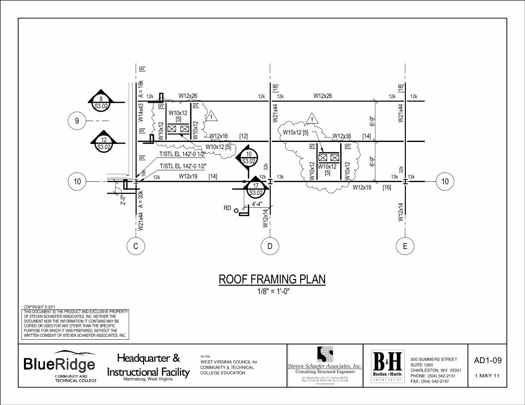
Item #39 S1.04 – Roof Framing Plan
A. Refer to exterior wall along Column Line #12 and delete Detail Tag 25/S3.01 between Column Lines K and L.
B. Refer to sketch AD1-08 and AD1-09 for floor openings.
Item #40 S2.01 – Foundation Sections
A. Refer to detail #1 and note that ALL footings require overexcavation 2’-0” min. below bottom of footing and backfill with engineered fill or lean concrete.
Item #41 S5.01 – Structural Notes
A. Refer to sketch AD1-10 for contingency notation. Attachments: Addendum items for Fire Protection, Mechanical, Electrical from Scheeser Buckley Mayfield, 7 pages Sketches AD1-1 through AD1-10, 10 pages Total Number of Pages 25

1 5 4 0 C o r p o r a t e W o o d s P a r k w a y , U n i o n t o w n , O h i o 4 4 6 8 5 - 8 7 9 7 • ( 3 3 0 ) 8 9 6 - 4 6 6 4 • F a x : ( 3 3 0 ) 8 9 6 - 9 1 8 0
3 0 0 M a r c o n i B o u l e v a r d , S u i t e 3 0 6 , C o l u m b u s , O h i o 4 3 2 1 5 • ( 6 1 4 ) 4 4 8 - 1 4 9 8 • F a x : ( 6 1 4 ) 4 4 8 - 1 4 9 8
Scheeser
Buckley
Mayfield LLC Consulting
Engineers
Principals:
Michael P. Wesner, P.E.
James P. Kulick, P.E.
James E. Eckman, P.E.
Kevin M. Noble, P.E.
Marlon C. Hathaway, P.E.
Christopher J. Schoonover, P.E.
Vincent J. Feidler, P.E.
Joshua J. Roehm, P.E.
Chad B. Montgomery, P.E.
Ronald R. Radabaugh, P.E.
Senior Associate:
John A. McDonough, P.E.
April 20, 2011
Bastian & Harris Architects
BB&T Square
300 Summers St., Suite 1200
Charleston, WV 25301-1630
Attn: Chris Campbell
RE: Blue Ridge CTC
Addendum #1
Dear Chris:
Please include the following items in the next addendum issued by your office for the above referenced
project:
MECHANICAL
Item 1: Specification Section 15010 – Basic, Mechanical Requirements
a. Refer to Article 3.1 and note that the Contractor shall provide the system commissioning as
indicated. The Owner will retain an Independent Commissioning Agent to perform third-
party commissioning. The contractor shall include the costs associated with performing pre-
functional and functional testing work as directed by the commissioning agent.
b. Refer to Article 3.10, paragraph A and note that sprinkler heads are not required to be
positioned in the center of the lay-in ceiling tiles except where noted on drawings
Item 2: Specification Section 15300 – Fire Protection
a. Refer to Article 3.10, paragraph A and note that sprinkler heads are not required to be
positioned in the center of the lay-in ceiling tiles except where noted on the drawings.
Item 3: Specification Section 15410 – PLUMBING PIPING – Make note of the following:
a. All no hub coupling shall be Heavy Duty, Type 304, Stainless Steel Couplings: ASTM A 666,
Type 304, stainless-steel shield; stainless-steel bands; and sleeve.
Item 4: Specification Section 15510 – HYDRONIC PIPING – Make note of the following:
a. In paragraph 2.11.A, change buffer tank connection size from 6” to 8”.
b. Add paragraph 3.1.C.2: Grooved mechanical fittings and couplings for use with scheduled 40
steel grooved end piping may be used in lieu of welded piping joint and fitting.
Item 5: Specification Section 15836 – AXIAL FANS – Make note of the following:
a. Add the following paragraph 2.1.:
b. 2.1. – Air Flow monitoring station: Flow monitoring station shall monitor the pressure
difference between the fan inlet and the smallest diameter of the inlet cone. Volumetric
flow to be calculated from empirically derived formulas based on testing by the fan
manufacturer. Flow monitoring station shall not use air restricting probes that reduce fan
performance or create additional fan sound.. Four (4) equidistantly spaced sensor orifices to
be drilled in the smallest diameter of the inlet cone venturi. Flow tubes from each venturi

Page 2
sensor to extend to a termination plate mounted on the fan housing. High-pressure flow
probe(s) to be mounted in low velocity fan inlet. Flow probes from the high-pressure sensor
shall extend to a termination plate mounted on the fan housing. Termination plate shall
include a low-pressure connection, a high-pressure connection, and a listing of the
empirically determined flow rate coefficient. Flow monitoring station shall accurately
measure the pressure differential to within +/- 3%. Flow monitoring station to be installed
by the fan manufacturer as part of the standard fan assembly. Flow monitoring station to be
supplied with electronics package that includes pressure transmitter and LCD digital readout.
Item 6: Specification Section 15731Central Station Air Handling Units – Make note of the following:
a. Add the following paragraph to section 2.5 Fans: The fan shall have an airflow measurement
system to measure fan airflow directly or to measure differential pressure that can be used
to calculate fan airflow. The system shall predict airflow within +/-5 percent total accuracy
(device and transmitter) when operating within the stable operating region of the fan curve.
The submitted fan airflow performance and noise levels shall not be affected by the
installation of the device. Any device that provides an obstruction to the fan inlet will not be
accepted.
Item7: Section 15990 – Testing, Adjusting, and Balancing
A. Refer to Article 1.4, paragraph c and note that additional TAB contractors may be approved
if contractor provides substitution request and associated cost proposal.
Item 8: Drawing M2.1 – Make Note of the following:
a. Return air duct size for return air grille between column lines B and C shall be 22” x 10”.
b. 12” x 12” duct work in room 1144 is duct type #6.
c. In room 1144 12” x 12” exhaust ductwork connects to a 4’ x 4’ Warming Oven Exhaust
Canopy. The 12” x 12” ductwork shall slope from fan back to the Exhaust Canopy. The
exhaust canopy in room 1144 is designated by the 4’ x 4’ square. The exhaust canopy shall
have an exhaust volume of 1600 CFM. See the specification section 15889 Kitchen Hood
Ventilation Systems for the requirements for this exhaust canopy. See Drawing M3.2 for the
Exhaust Canopy detail.
d. In coded note 20 on this drawing add the following sentence to this note: “The relief air
plenum shall have the same construction specification and insulation specification as the
outside air plenum.”
e. Make the following changes to VAV terminal number 11 serving room 1305: See the
revisions to the “SINGLE DUCT VAV TERMINAL SCHEDULE” in this addendum for size and
performance changes. Change inlet duct size to 12”x10”. Change outlet duct size to
12”x10”. Change diffuser CFM in room 1305 to 125. Add a diffuser type A with a CFM of
175 in the corridor to the south of room 1305.
Item 9: Drawing M2.2 – Make Note of the Following:
a. The return air boot ductwork shall extend 3 feet past the corridor wall for rooms 2105, 2115,
2125, 2135, 2110, 2120, 2130, 2140, 2145, 2150. The duct size for these return air boots
shall be 22” x 14”.
b. Add electric wall heater EWH-1 on outside wall in room 2155.
c. In coded note 19 on this drawing add the following sentence to this note: “The relief air
plenum shall have the same construction specification and insulation specification as the
outside air plenum.”
Item 10: Drawing M2.3 – Make Note of the Following:
a. Note in section BB and section AA the outside air plenum and relief air plenums shall be
approximately 12 feet tall.
Page 3
b. In coded note 47 on this drawing add the following sentence to this note: “The outside air
plenum shall have the same construction specification and insulation specification as the
relief air plenum.”
c. Add a diffuser type A, rated at 200 CFM down stream of VAV terminal 116. Diffuser shall be
installed at the end of the corridor to the South of room 3300. Connect the diffuser to the
18”x10” duct run downstream of the terminal.
d. Ductwork type between the general exhaust grilled and the General Exhaust Air Terminals
shall be type 1
Item 11: Drawing M2.4 – Make Note of the Following:
a. In pump room add the tag UH-1 to the unit heater.
b. Attach fume hood exhaust ductwork to building wall with stainless steel angles.
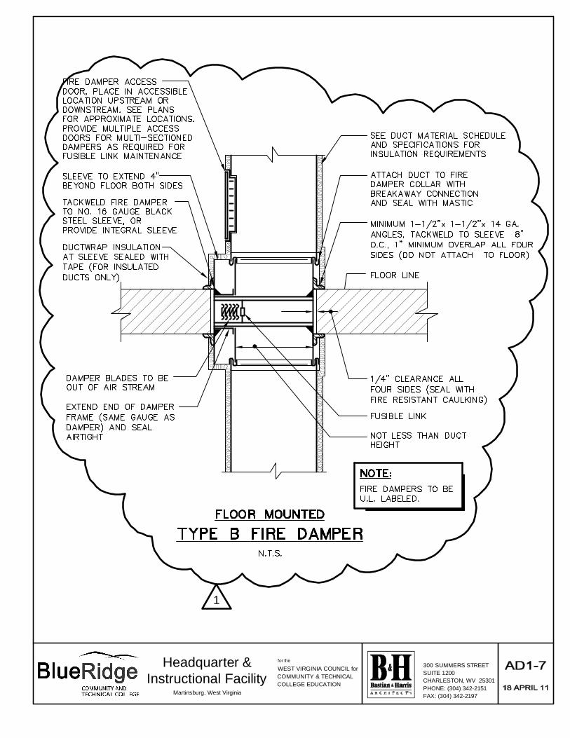
Item 12: Drawing M3.1 – Make Note of the Following:
a. Add attached sketch AD1-6 - WALL MOUNTED TYPE B FIRE DAMPER DETAIL to this drawing.
b. Add attached sketch AD1-7 - FLOOR MOUNTED TYPE B FIRE DAMPER DETAIL to this drawing.
Item 13: Drawing M4.1 – Make Note of the Following:
a. In the HYDRONIC PUMP SCHEDULE change the GPM from 660 to 670 GPM.
b. In the CHILLER SCHEDULE change the GPM from 560 to 660 GPM.
c. In the FAN SCHEDULE Change EF-5 total static pressure from 4 inch to 7 inch water column.
Maximum BHP shall be 2.53. Fan RPM shall be 4,344. Motor horsepower to be 5 HP.
d. In the ENVIRONMENTAL CONDITIONING UNIT SCHEDULE make note of the following:
1. Delete notes 5 and 6 from this schedule
2. Change ECU-3 to a heat pump unit from a cooling only unit. This unit shall be able to
both heat and cool.
e. In the ELECTRIC UNIT HEATER SCHEDULE change the heater voltage to 460/3. Change the
model to P3P5605T.
Item 14: Drawings M4.2 – Make Note of the Following:
a. In the VARIABLE FREQUENCY DRIVE SCHEDULE change the horsepower on VFD-5 from 20HP
to 30HP.
b. Under the DUCT MATERIAL SCHEDULE make note of the following:
1) Change duct type pressure classification from 4” to 6”.
2) Change duct type #3 from 2” to 3” pressure classification.
c. Under the SINGLE DUCT VAV TERMINAL UNIT SCHEDULE make note of the following:
1. Change terminal number 3 as follows: change the coil KW to 10KW.
2. Change terminal number 11 as follows: inlet size to be 6, coil KW to be 3 KW.
3. Change terminal number 30 as follows: coil KW to be 8 KW.
4. Change terminal number 61 as follows: coil KW to be 10 KW.
5. Change terminal number 62 as follows: inlet size to be 12.
6. Change terminal number 64 as follows: inlet size to be 12.
7. Change terminal number 71 as follows: inlet size to be 8, coil KW to be 3.5 KW
8. Change terminal number 72 as follows: coil KW to be 3.5 KW.
9. Change terminal number 73 as follows: inlet size to be 8, coil KW to be 3.5KW.
10. Change terminal number 94 as follows: inlet size to be 10, coil KW to be 6.5
KW.
11. Change terminal number 101 as follows: inlet size to be 12.
12. Change terminal number 116 as follows: inlet size to be 12.
13. Change terminal number 135 as follows: inlet size to be 6, coil KW to be 3.0.
14. Change terminal number 154 as follows: inlet size to be 12.
15. Change terminal number 155 as follows: inlet size to be 12.
16. Change terminal number 156 as follows: inlet size to be 12.

Page 4
Item 15: Drawing M6.3 – Make Note of the Following:
a. Add a start stop output to ‘AHU-3 control panel. Label this start stop output SMOKE
DAMPERS. The output shall control the floor mounted smoke dampers installed in the
supply and return ducts. Add a “RELAY IN A BOX (RIB)” to the 120V/1 power to the smoke
dampers. The output shall connect to the coil side of the RIB. The control sequence shall
open the dampers whenever the unit runs and close the dampers when the unit is off.
Item 16: Drawing M6.4 – Make Note of the Following:
a. Add a level sensor to the glycol fill tank and add a binary input to the DDC panel. An alarm
shall be generated if the level in the glycol tank is too low.
PLUMBING
Item 1: Refer to drawing P2.4
a. Refer to attached sketch AD1-1 for installation of trap primer to floor drain.
b. Relocate vent piping though roof near column line E-9 five feet to east as not to conflict with
mechanical equipment. Relocate vent piping on floor below to match.
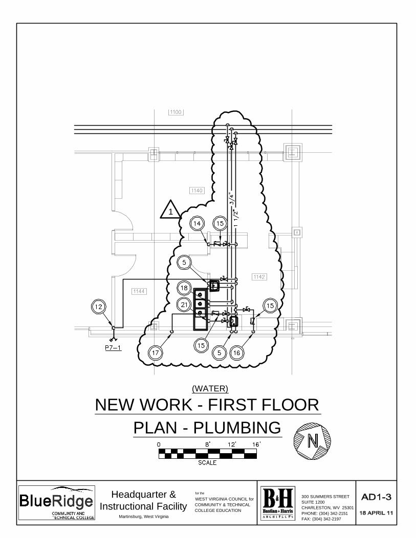
Item 2: Refer to drawing P3.1
a. Refer to attached sketch AD1-2 for installation of trap primer to floor drains.
b. Refer to attached sketch AD1-3 for installation of recirc. domestic hot water piping and pipe
sizes.
c. Modify coded note #17 to read: ½” DCW piping with double check valve down to ice maker.
Install “Aqua-Pure” inline ice maker filter next to unit for easy access. Make rough-in and
final connections.”
Item 3: Refer to drawing P3.2
a. Refer to attached sketch AD1-4 for installation of trap primer to floor drain.
Item 4: Refer to drawing P3.3
a. Refer to attached sketch AD1-5 for installation of trap primer to floor drain.
Item 5: Refer to drawing P4.1
a. Delete note regarding gas vent piping on detail “Hot Water Heater Schematic”.
FIRE PROTECTION
Item 1: Refer to drawing FP1.1
a. Modify note to “Gate valve with tamper switch” on “Fire Service Entrance Schematic”.
ELECTRICAL
Item 1: Drawing E2.01 – Refer to coded notes # 3 & # 4 and note that this work is part of the force main
and is base bid. Delete adjacent note regarding then Fire Pump House. Refer to coded note #2 and note
that this work is part of Alternate No. 7 for the fire pump house.
Page 5
Item 2: Drawing E3.00 – Lighting – First Floor Plan - Electrical
a. Refer to bollards ‘BL’ at the rear terrace and note that these are to be provided as part of
Alternate No. 4.
Item 3: Drawing E3.01, Power/Feeder Routing - First Floor Plan - Electrical:
a. Refer to Vestibule 1145. Relocate EVCS and associated circuit from vestibule into lobby 1150
and west wall under stair landing. Coordinate location with Architect.
b. Refer to Room 1170. Add receptacle on North wall to left of FACP for Sump Pump Alarm
Panel. Provide homerun to panel ‘1LA’ and connect to 20A/1P circuit breaker. Revise
panelboard schedule.
Item 4: Drawing E3.02, Systems - First Floor Plan - Electrical:
a. Refer to Room 1110. Add one (1) duct smoke detector for a total of 5 in room. Coordinate
exact location with mechanical contractor prior to rough-in.
b. Refer to Room 1110. Add one (1) flow and one (1) tamper switch. Coordinate exact location
with plumbing contractor.
c. Refer to Room 1170. Add one (1) flow and one (1) tamper switch. Coordinate exact location
with plumbing contractor.
d. Refer to Vestibule 1145. Relocate EVCS and associated smoke detector from vestibule into
lobby 1150 on west wall under stair landing. Coordinate location with Architect.
e. Refer to Lobby 1150, east wall, fire alarm annunciator panel. Delete panel and associated
smoke detector.
Item 5: Drawing E3.03, Power/Mechanical Connections-First Floor Plan-Electrical:
a. Refer to Lobby 1145. Electric Heaters to be ceiling mount. Coordinate exact location with
mechanical contractor prior to rough-in.
b. Refer to Telecommunications Room 1315. Condensing Units shall be wall mounted.
Coordinate exact locations with mechanical contractors prior to rough-in.
c. Refer to Security Desk 1160 in Lobby. Move wall heater to North wall of desk. Coordinate
exact location with mechanical contractor prior to rough-in.
d. Refer to Restroom Corridor. Relocate ‘ERC-3.5’ south to Main Corridor.
e. Refer to Room 1144. Relocate Exhaust Fan EF-11 (1HP,480V,3-phase) from Roof to south
wall of 1144. Locate combination motor starter/disconnect switch on south wall of Room
1144. Provide homerun to panelboard ‘1LA’. Provide one (1) 15A/3P circuit breaker. Revise
panelboard schedule.
f. Refer to Restrooms 1185 and 1190. Move electric wall heaters further north onto chase wall.
Coordinate exact location with mechanical contractor prior to rough-in.
g. Refer to coded note 26. Revise KW rating from 143KW to 149KW.
h. Refer to Room 1105. Revise coded note number 12 to be new coded note 32. New coded
note 32 to read “VAV with reheat (10kW,480V,3Ø). Unit furnished with integral disconnect
and starter.” Revise feeder shown between rooms 1105, 1115, and 1135 to be 50B. Revise
feeder breaker shown on VAV in room 1135 to be 50A/3P and revise panelboard schedule.

Page 6
i. Refer to Room 1305. Revise coded note number 19 to be new coded note 33. New coded
note 33 to read “VAV with reheat (3kW,480V,3Ø). Unit furnished with integral disconnect
and starter.” Revise feeder breaker shown on VAV 35A/3P and revise panelboard schedule.
Revise all wiring associated with this homerun to be feeder 35B.
j. Refer to Room 1205. Revise coded note number 11 to be new coded note 34. New coded
note 34 to read “VAV with reheat (8kW,480V,3Ø). Unit furnished with integral disconnect
and starter.” Revise feeder shown between rooms 1205, 1200, 1100, and 1175, to be 45B.
Revise feeder breaker shown on VAV in room 1175 to be 45A/3P and revise panelboard
schedule.
Item 6: Drawing E4.02, Systems – Second Floor Plan – Electrical:
a. Refer to Room 2155. Add one (1) duct smoke detector for a total of 4 in room.
Item 7: Drawing E4.03, Mechanical Connections – Second Floor Plan – Electrical:
a. Refer to Restrooms 2165 and 2170. Move electric wall heaters further north onto chase wall.
Coordinate exact location with mechanical contractor prior to rough-in.
b. Refer to reheat coil and associated homerun in restroom corridor. Revise circuit breaker
from 30A/3P to 40A/3P. Revise all wiring associated with this homerun and downstream
equipment to be feeder 40B .
c. Revise VAV with reheat coil in rooms 2315, 2325 and 2335 to be ERC-5, and associated
coded notes to be new coded note number 28. Coded note 28 to read “VAV with reheat
(5kW,480V,3Ø). Unit furnished with integral disconnect and starter”.
d. Refer to reheat coil and associate homerun in Room 2340. Revise circuit breaker from
20A/3P to 25A/3P. Revise all wiring from 3-#12, 1-#12G to 3-#10, 1-#10G. Revise ERC-2 in
room 2340 to ERC-5 (5KW) and ERC-3 to ERC-2 (2KW).
e. Refer to reheat coil and associated homerun in Room 2350. Revise circuit breaker from
30A/3P to 40A/3P. Revise all wiring associated with this homerun and downstream
equipment from #10’s indicated to feeder 40B. Revise ERC-3 in room 2350 to ERC-7.5
(7.5KW). Revise associated coded note to be new coded note 29. Coded note 29 to read
“VAV with reheat coil (7.5kW,480V,3Ø). Unit furnished with integral disconnect and
starter”.
f. Refer to coded note 20. Revise KW rating from 53 KW to 56 KW.
g. Refer to Room 2155, EPC-2. Revise feeder and associated circuit breaker from 80B to 85B.
Revise circuit breaker from 80A/3P to 85A/3P.
h. Refer to Room 2105. Revise reheat coil from ERC-8 to an ERC-10. Revise coded note
reference to number 11.
Item 8: Drawing E5.01, Power – Third Floor Plan – Electrical:
a. Refer to Lab Room 3130, junction box for lab hood (12A,120V,1-phase). Delete junction box
and provide a receptacle at the right rear side of cabinet at a height even with the top of the
bench. Provide a 20A/1P GFCI circuit breaker in separate enclosure near receptacle. Connect
to circuit ‘3L-BIO, cct. 18’.
b. Refer to Room 3165. Provide 20A/1P, 120V circuit for air dryer. Connect to panelboard 3LA.
Coordinate exact location with mechanical contractor.
Item 9: Drawing E5.03, Power/Mechanical Connections – Third Floor Plan – Electrical:
a. Refer to coded note 25. Revise KW rating from 180KW to 214KW. Revise associated feeder
and circuit breaker from 300B to 325B. Revise circuit breaker size from 300A/3P to 325A/3P.
Page 7
b. Refer to coded note 26. Revise KW rating from 4KW to 5KW. Refer to associated unit in
Room 3165. Relocate unit to center of room. Coordinate exact location with mechanical
contractor. Revise circuit breaker size from 20A/1P to 25A/1P. Revise wiring size from 2-#12,
1-#12 G to 2-#10, 1-#10G.
c. Refer to ERC-10.5 located outside of Room 3300. Relocate to Room 3200. Coordinate exact
location with mechanical contractor prior to rough-in.
d. Refer to Room 3115. Revise ERC-2.5 to be ERC-3. Revise associated coded note from
number 5 to be number 8.
Item 10: Drawing E5.04, Lighting/Power/Systems/Feeder Routing – Roof Plan/Penthouse Plan - Electrical:
a. Refer to exhaust fans EF-3, 4, 5, 6, 7, 8, 9, 10. Provide one (1) 30A/600V/3P/N3R/NF
disconnect switch near fan location. Mount on wall as required.
b. Refer to pump room, Glycol Pump. Relocate pump to Room 3165 below. Feed from
panelboard ‘3LA’.
c. Refer to exhaust fan EF-5. Revise HP from 3HP to 5 HP.
d. Refer to exhaust fan EF-2. Revise horsepower from 2HP to 5HP.
e. Refer to Motor Starter Schedule EF-2. Revise horsepower from 2HP to 5HP. Revise fuse size
from 6.25A to 15A.
f. Refer to Motor Starter Schedule EF-5. Revise horsepower from 3HP to 5HP. Revise fuse size
from 8A to 15A.
g. Refer to Motor Starter Schedule EF-11. Revise horsepower from 3HP to 1HP. Revise fuse size
from 8A to 4A.
h. Refer to roof outside of pump room. Add ACCU-10. Provide 2-#12, 1-#12G, ¾”C. Provide
homerun to panelboard ‘3LC’. Provide 20A/2P circuit breaker. Provide interconnection to
indoor unit ECU-10 in pump room. Coordinate exact location with mechanical contractor
prior to rough-in.
i. Refer to ACCU-3 and 4. Revise wire size from 2-#12,1-#12G to 2-#8, 1-#10G.
j. Refer to ACCU-5. Revise wire size from 2-#12, 1-#12G to 2-#10, 1-#10G.
k. Refer to Motor Starter Schedule. Furnish and install phase loss, over-voltage, under-voltage
relay in all 3-phase motor starters.
Item 11: Specification 16670, Lightning Protection:
a. Refer to Section 2.1, Manufacturers. Add Robbins Lightning Protection as an approved
manufacturer.
Item 12: General for all Power/Mechanical Connection Plans:
a. Coordinate exact location and labeling schemes with Mechanical Drawings prior to rough-in
and label making. Labels shall be per Mechanical Drawings.
If you have any questions regarding the above, please do not hesitate to call.
Very truly yours,
Scheeser Buckley Mayfield LLC
Michael P. Wesner, P.E., LEED AP, CBCP
V.P. Mechanical Engineering
Attachments: Sketches AD1-1 - AD1-7
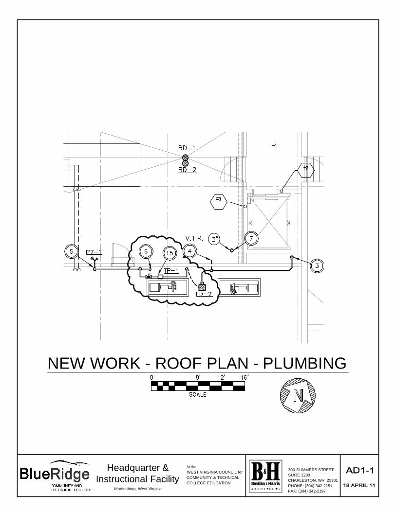
NEW WORK - ROOF PLAN - PLUMBING
for the
WEST VIRGINIA COUNCIL forCOMMUNITY & TECHNICALCOLLEGE EDUCATION
300 SUMMERS STREETSUITE 1200CHARLESTON, WV 25301PHONE: (304) 342-2151FAX: (304) 342-2197
Headquarter &Instructional Facility
Martinsburg, West Virginia

1
NEW WORK - FIRST FLOOR(WATER)
PLAN - PLUMBING
for the
WEST VIRGINIA COUNCIL forCOMMUNITY & TECHNICALCOLLEGE EDUCATION
300 SUMMERS STREETSUITE 1200CHARLESTON, WV 25301PHONE: (304) 342-2151FAX: (304) 342-2197
Headquarter &Instructional Facility
Martinsburg, West Virginia
1
NEW WORK - FIRST FLOOR(WATER)
PLAN - PLUMBING
for the
WEST VIRGINIA COUNCIL forCOMMUNITY & TECHNICALCOLLEGE EDUCATION
300 SUMMERS STREETSUITE 1200CHARLESTON, WV 25301PHONE: (304) 342-2151FAX: (304) 342-2197
Headquarter &Instructional Facility
Martinsburg, West Virginia

1
NEW WORK - SECOND FLOOR(WATER)
PLAN - PLUMBING
for the
WEST VIRGINIA COUNCIL forCOMMUNITY & TECHNICALCOLLEGE EDUCATION
300 SUMMERS STREETSUITE 1200CHARLESTON, WV 25301PHONE: (304) 342-2151FAX: (304) 342-2197
Headquarter &Instructional Facility
Martinsburg, West Virginia

1
NEW WORK - THIRD FLOOR(WATER)
PLAN - PLUMBING
for the
WEST VIRGINIA COUNCIL forCOMMUNITY & TECHNICALCOLLEGE EDUCATION
300 SUMMERS STREETSUITE 1200CHARLESTON, WV 25301PHONE: (304) 342-2151FAX: (304) 342-2197
Headquarter &Instructional Facility
Martinsburg, West Virginia

1
for the
WEST VIRGINIA COUNCIL forCOMMUNITY & TECHNICALCOLLEGE EDUCATION
300 SUMMERS STREETSUITE 1200CHARLESTON, WV 25301PHONE: (304) 342-2151FAX: (304) 342-2197
Headquarter &Instructional Facility
Martinsburg, West Virginia
1
for the
WEST VIRGINIA COUNCIL forCOMMUNITY & TECHNICALCOLLEGE EDUCATION
300 SUMMERS STREETSUITE 1200CHARLESTON, WV 25301PHONE: (304) 342-2151FAX: (304) 342-2197
Headquarter &Instructional Facility
Martinsburg, West Virginia

S4.027
M
M
N
N
1111
W18x50
[6, 3, 6]
17k
W21x57
[10,3,10]
38k
15k W14x30 [11] 15k
16k
W16x26 [12]
16k 22k
21k
W12x19
[6]
W14x22
[6]
8S3.01
A = 25k
A = 31k
A = 30k
4"
4"
W10x12 [6]W10x12
[6]
1
F G
101013k 12k
W12x19 [14]
12k
W12x14
W12x14
32k
24k
W12x16 [12]
W12x14
11kW10x12
[5]
W10x12
W10x12
[5]
1
AD1-08
1/8" = 1'-0"
SECOND FLOOR FRAMING PLAN 1/8" = 1'-0"
ROOF FRAMING PLAN
A R C H I T E C T S
BH&Bastian Harris&
Steven Schaefer Associates, Inc.Consulting Structural Engineers
1041 1 Me dal l i on Driv e, S ui t e 121 C inci nnat i , O H 45 241
www. ssas t ru ctur al . com
Phon e: 5 13-5 42- 3300 80 0-54 2-3 302 Fax : 5 13-5 42-5 540
1 MAY 11
Headquarter &Instructional Facility
Martinsburg, West Virginia
for the
WEST VIRGINIA COUNCIL for
COMMUNITY & TECHNICAL
COLLEGE EDUCATION
300 SUMMERS STREET
SUITE 1200
CHARLESTON, WV 25301
PHONE: (304) 342-2151
FAX: (304) 342-2197
COPYRIGHT © 2011THIS DOCUMENT IS THE PRODUCT AND EXCLUSIVE PROPERTYOF STEVEN SCHAEFER ASSOCIATES, INC. NEITHER THEDOCUMENT NOR THE INFORMATION IT CONTAINS MAY BECOPIED OR USED FOR ANY OTHER THAN THE SPECIFICPURPOSE FOR WHICH IT WAS PREPARED, WITHOUT THEWRITTEN CONSENT OF STEVEN SCHAEFER ASSOCIATES, INC.
C E
1010
92'-0"
8S3.02
12S3.02
A = 18k
W21x44
12k W12x19 [14] 12k 13k
W12x19 [16]
13k 13k
W12x14
W12x14
32k
W21x44
[18]
32k
W21x44
[18]
16k
W14x43
12k12k W12x26 12k
W12x16 [14]
T/STL EL 142'-0 1/2"
T/STL EL 142'-0 1/2"
12k W12x26 12k
W12x16 [12][5]
[5]
[5]
6'-9"
6'-9"
D
4'-4"A = 30k
17S3.02
10S3.02
RD
W10x12
[5]
W10x12
[5]
W10x12[5]
W10x12 [5]
W10x12 [5]
W10x12
[5]
W10x12
[5]
W10x12[5] 11
AD1-09
1/8" = 1'-0"
ROOF FRAMING PLAN
A R C H I T E C T S
BH&Bastian Harris&
Steven Schaefer Associates, Inc.Consulting Structural Engineers
1041 1 Me dal l i on Driv e, S ui t e 121 C inci nnat i , O H 45 241
www. ssas t ru ctur al . com
Phon e: 5 13-5 42- 3300 80 0-54 2-3 302 Fax : 5 13-5 42-5 540
1 MAY 11
Headquarter &Instructional Facility
Martinsburg, West Virginia
for the
WEST VIRGINIA COUNCIL for
COMMUNITY & TECHNICAL
COLLEGE EDUCATION
300 SUMMERS STREET
SUITE 1200
CHARLESTON, WV 25301
PHONE: (304) 342-2151
FAX: (304) 342-2197
COPYRIGHT © 2011THIS DOCUMENT IS THE PRODUCT AND EXCLUSIVE PROPERTYOF STEVEN SCHAEFER ASSOCIATES, INC. NEITHER THEDOCUMENT NOR THE INFORMATION IT CONTAINS MAY BECOPIED OR USED FOR ANY OTHER THAN THE SPECIFICPURPOSE FOR WHICH IT WAS PREPARED, WITHOUT THEWRITTEN CONSENT OF STEVEN SCHAEFER ASSOCIATES, INC.

AD1-10
1
A R C H I T E C T S
BH&Bastian Harris&
Steven Schaefer Associates, Inc.Consulting Structural Engineers
1041 1 Me dal l i on Driv e, S ui t e 121 C inci nnat i , O H 45 241
www. ssas t ru ctur al . com
Phon e: 5 13-5 42- 3300 80 0-54 2-3 302 Fax : 5 13-5 42-5 540
1 MAY 11
Headquarter &Instructional Facility
Martinsburg, West Virginia
for the
WEST VIRGINIA COUNCIL for
COMMUNITY & TECHNICAL
COLLEGE EDUCATION
300 SUMMERS STREET
SUITE 1200
CHARLESTON, WV 25301
PHONE: (304) 342-2151
FAX: (304) 342-2197
COPYRIGHT © 2011
THIS DOCUMENT IS THE PRODUCT AND EXCLUSIVE PROPERTY
OF STEVEN SCHAEFER ASSOCIATES, INC. NEITHER THE
DOCUMENT NOR THE INFORMATION IT CONTAINS MAY BE
COPIED OR USED FOR ANY OTHER THAN THE SPECIFIC
PURPOSE FOR WHICH IT WAS PREPARED, WITHOUT THE
WRITTEN CONSENT OF STEVEN SCHAEFER ASSOCIATES, INC.