Embed Size (px)
Citation preview

Prof. B V S Viswanadham, Department of Civil Engineering, IIT Bombay
20

Prof. B V S Viswanadham, Department of Civil Engineering, IIT Bombay
Module 5:
Lecture -2 on Stability of Slopes

Prof. B V S Viswanadham, Department of Civil Engineering, IIT Bombay
Analysis of finite slopes Possible failure surfaces
Planar failure surface: Occurs along a specific plane or weakness
Excavations into stratified deposits (where strata dippingtoward the excavation); In earth dams along sloping cores ofweak material (not likely to occur in homogenous soils)Circular failure surface:
Soils exhibiting cohesion c or c and φ and no specific planes ofweakness or great strength.
Non circular failure surface
When the distribution of shearing resistance within an earthmass is non-uniform, failure can occur along surfaces morecomplex than a circle.
Prof. B V S Viswanadham, Department of Civil Engineering, IIT Bombay
A finite slope with possible failure surfaces
1VnH
Prof. B V S Viswanadham, Department of Civil Engineering, IIT Bombay
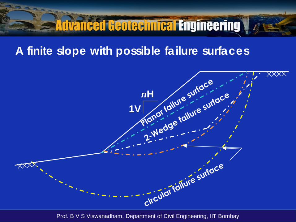
Typical patterns of rotational slides
a) Spoon-shaped b) cylindrical-shaped
Prof. B V S Viswanadham, Department of Civil Engineering, IIT Bombay
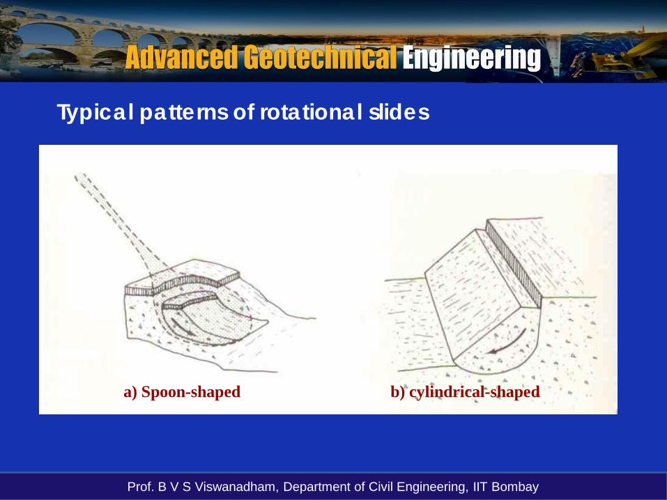
Effective or Total stress parameters ?Short-term
• Low Permeability Soil, e.g. Clays:At the end of construction the soil is almost stillundrained. Hence total stress analysis making use ofundrained shear strength Cu is adopted.
• Free Draining Materials, e.g. sands/gravels:Drainage takes place immediately and hence effective stress parameters c′ and φ′ are used.
Long-termAfter a relatively long period of time, the fully drainedstage will have been reached, and hence effectivestress parameters c′ and φ′ are used.
Prof. B V S Viswanadham, Department of Civil Engineering, IIT Bombay
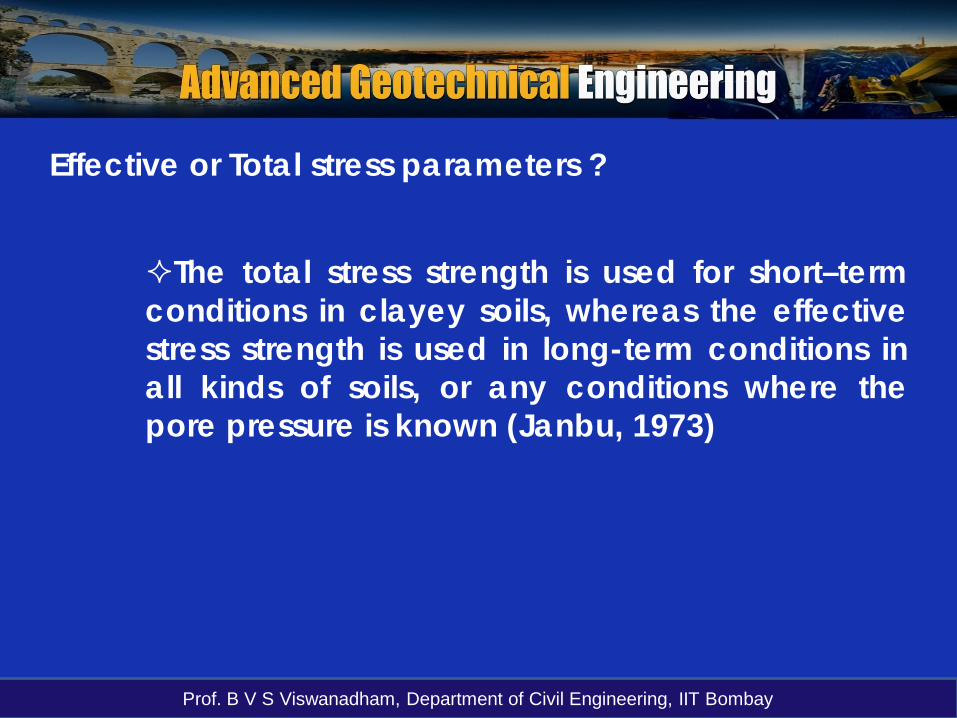
The total stress strength is used for short–termconditions in clayey soils, whereas the effectivestress strength is used in long-term conditions inall kinds of soils, or any conditions where thepore pressure is known (Janbu, 1973)
Effective or Total stress parameters ?

Prof. B V S Viswanadham, Department of Civil Engineering, IIT Bombay
Analysis of finite slopes
The Factor of Safety for finite slope depends on:
Assumed location of centre of rotation for the slip surface
Radius of failure surface
Type of failure (toe failure, base failure and slope failure).
Prof. B V S Viswanadham, Department of Civil Engineering, IIT Bombay
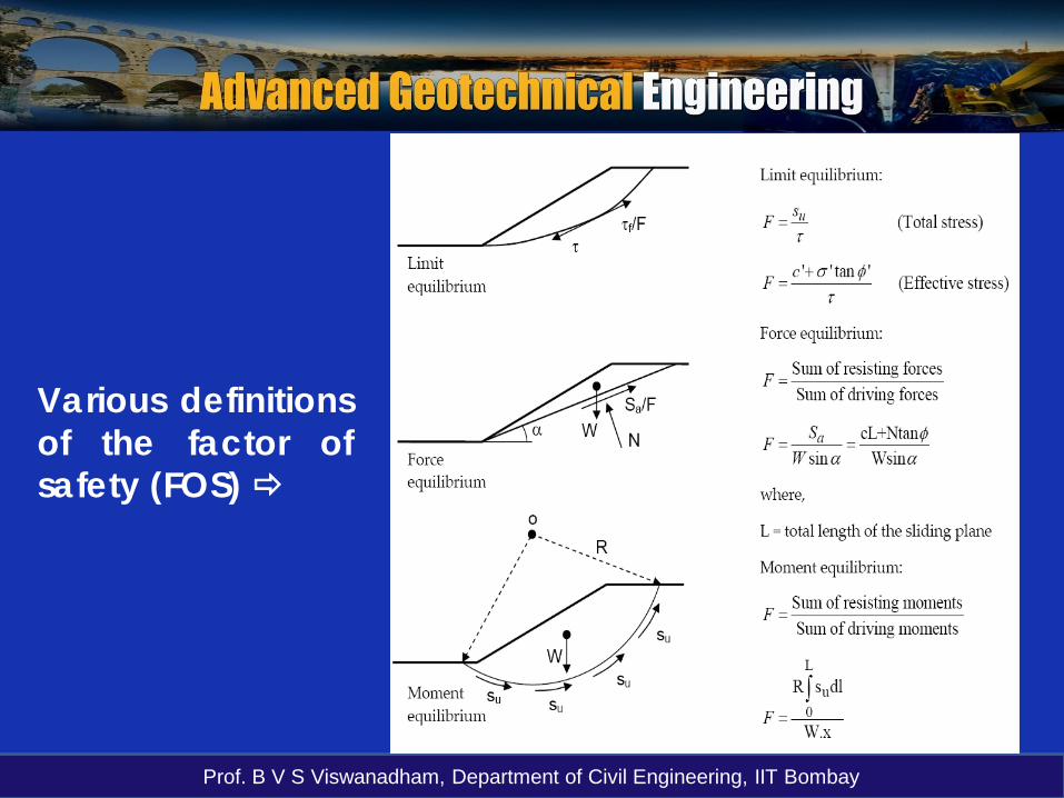
Various definitionsof the factor ofsafety (FOS)

Prof. B V S Viswanadham, Department of Civil Engineering, IIT Bombay
Review of Stability Analysis MethodsAll limit equilibrium methods utilize the Mohr-Coulombexpression to determine the shear strength τf along thesliding surface.
The available shear strength τf depends on the type of soil andthe effective normal stress, whereas the mobilized shear stress τdepends on the external forces acting on the soil mass.
Prof. B V S Viswanadham, Department of Civil Engineering, IIT Bombay
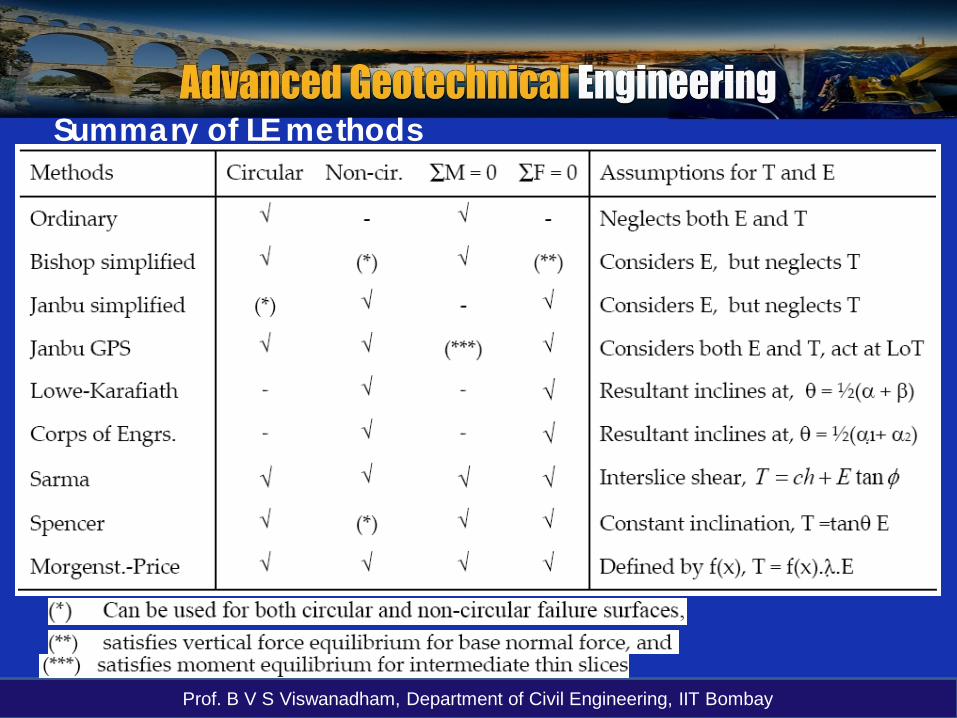
Summary of LE methods
Prof. B V S Viswanadham, Department of Civil Engineering, IIT Bombay
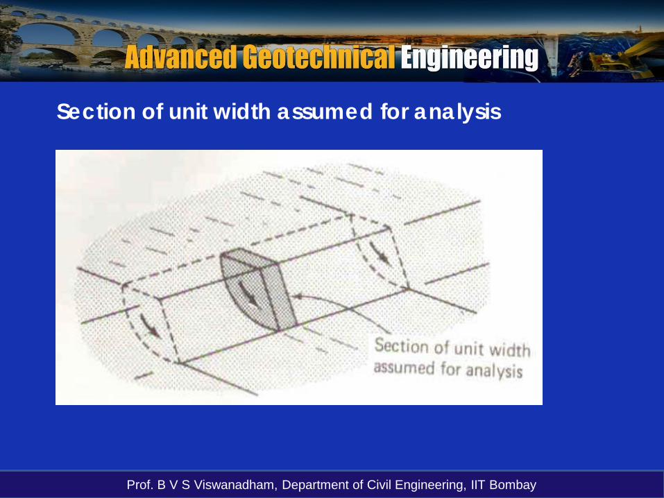
Section of unit width assumed for analysis

Prof. B V S Viswanadham, Department of Civil Engineering, IIT Bombay
θ
dW
cu
R
R
Circular analysis – un-drained condition or φu = 0 analysis
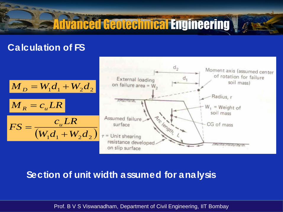
Analysis in terms of totalstresses and applies to theshort-term condition for acutting or embankmentassuming soil profile tocomprise fully saturated clay.
D
R
MMFS =
( )Wd
RLcFS Au=
Demerit: Determination of W and d
Prof. B V S Viswanadham, Department of Civil Engineering, IIT Bombay
Calculation of FS
2211 dWdWM D +=
LRcM uR =
( )2211 dWdWLRcFS u
+=
Section of unit width assumed for analysis
Prof. B V S Viswanadham, Department of Civil Engineering, IIT Bombay
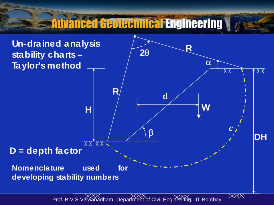
Un-drained analysis stability charts –Taylor’s method
2θ
dW
c
R
R
β DH
H
α
Nomenclature used fordeveloping stability numbers
D = depth factor

Prof. B V S Viswanadham, Department of Civil Engineering, IIT Bombay
Un-drained analysis stability charts – Taylor’s method
WdcLRFS =
W = f (γ, H, geometry of failure surface)
⇔ Geometry of failure surface can be characterized by the three angles α, β, and θ
(1)
Rewriting (1): ( )θβαγ ,,HfcFSc
r ==
cr = required cohesion to just maintain a stable slope andf (α, β, θ) is pure number, designated as the Stability number Ns
HcN r
s γ=Taylor’s Stability number
FS is lowest Factor of safetyobtained from circular arcanalysis.

Prof. B V S Viswanadham, Department of Civil Engineering, IIT Bombay
Taylor’s curves
β > 53°
Slope inclination β
β [°] Ns
60 0.191
65 0.199
70 0.208
75 0.219
80 0.232
85 0.246
90 0.261
For φ = 0 soils
Prof. B V S Viswanadham, Department of Civil Engineering, IIT Bombay
Un-drained analysis stability charts – Taylor’s method
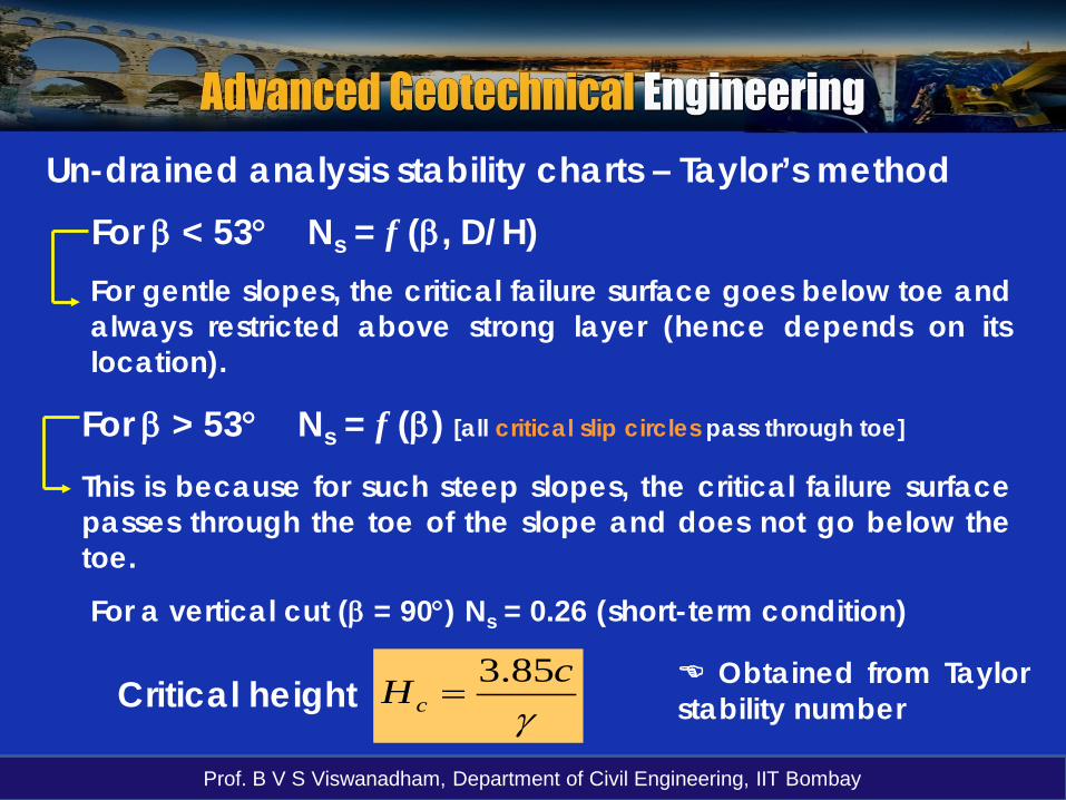
This is because for such steep slopes, the critical failure surfacepasses through the toe of the slope and does not go below thetoe.
γcHc
85.3=Critical height
For β < 53° Ns = f (β, D/H)
For β > 53° Ns = f (β) [all critical slip circles pass through toe]
For gentle slopes, the critical failure surface goes below toe andalways restricted above strong layer (hence depends on itslocation).
For a vertical cut (β = 90°) Ns = 0.26 (short-term condition)
Obtained from Taylorstability number

Prof. B V S Viswanadham, Department of Civil Engineering, IIT Bombay
Un-drained analysis stability charts – Taylor’s method
Position of the critical slip circle ( for FS = 1) may be limited by two factors:
a) The depth of stratum in which sliding can occur
b) The possible distance from the toe of the rupture surface to the toe of the slope.

Prof. B V S Viswanadham, Department of Civil Engineering, IIT BombayDepth factor D/H
Stability numbers for homogeneous simple slopes for φ = 0
After Taylor (1948)
For example:
By knowing D/H and β -- Nsand n can be obtained fromthis chart
n = 0.65
For D/H = 1; β > 53°n = 0
Prof. B V S Viswanadham, Department of Civil Engineering, IIT Bombay
Un-drained analysis stability charts – Taylor’s methodImportant points: It is necessary to ignore possibility of tensioncracks – otherwise geometrically similar failuresurfaces do not occur on slopes having differentheights --- hc = f (c and γ) and is not proportional to H.
Taylor’s stability numbers were determined froman analysis of total stress only.
Taylor’s method is practically restricted toproblems involving un-drained saturated clays orto much common cases where the pore pressureis everywhere zero.
Prof. B V S Viswanadham, Department of Civil Engineering, IIT Bombay
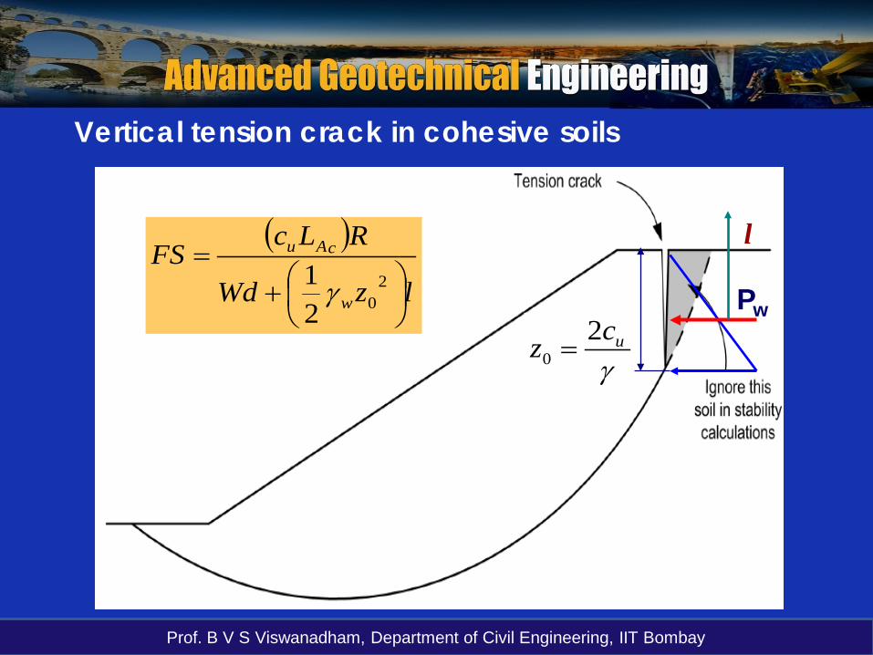
γucz 2
0 =
Pw
Vertical tension crack in cohesive soils
( )lzWd
RLcFS
w
cAu
+
=2
021 γ
l
Prof. B V S Viswanadham, Department of Civil Engineering, IIT Bombay
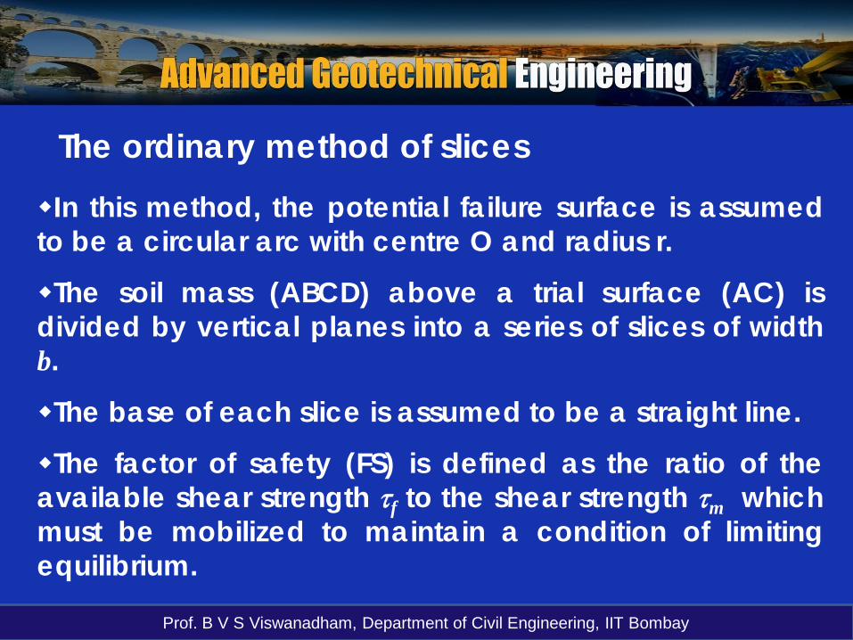
The ordinary method of slicesIn this method, the potential failure surface is assumedto be a circular arc with centre O and radius r.
The soil mass (ABCD) above a trial surface (AC) isdivided by vertical planes into a series of slices of widthb.
The base of each slice is assumed to be a straight line.
The factor of safety (FS) is defined as the ratio of theavailable shear strength τf to the shear strength τm whichmust be mobilized to maintain a condition of limitingequilibrium.
Prof. B V S Viswanadham, Department of Civil Engineering, IIT Bombay
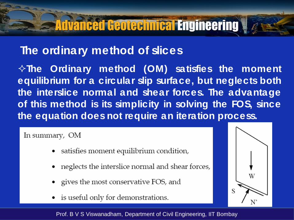
The Ordinary method (OM) satisfies the momentequilibrium for a circular slip surface, but neglects boththe interslice normal and shear forces. The advantageof this method is its simplicity in solving the FOS, sincethe equation does not require an iteration process.
The ordinary method of slices

Prof. B V S Viswanadham, Department of Civil Engineering, IIT Bombay
rsinα
r
r
h
α
b
A B
CD
l
α
X2
X1
E1
E2
α
FBD of slice i
The method of slices
OLA = length of arc AC

Prof. B V S Viswanadham, Department of Civil Engineering, IIT Bombay
The method of slices
m
fFSττ
=The FS is taken to be the same for eachslice, implying that there must be mutualsupport between slides. i.e. forces must actbetween slices.
1. Total weight of slice W = γbh
2. Total normal force N = σl ( includes N′ = σ′l and U = ul)u = PWP at the centre of the base and l is the length of the base.
3. The shear force on the base, T = τml
4. Total normal forces on sides E1 and E2
5. The shear forces on the sides, X1 and X2

Prof. B V S Viswanadham, Department of Civil Engineering, IIT Bombay
The method of slices Considering moments about O, the sum of themoments of the shear forces T on the failure arc ACmust be equal the moment of the weight of the soilmass ABCD.
∑ ∑= αsinWrTr
( )∑ ∑= ατ
sinWlFS
f
Using ( ) lFSlT f
m
ττ ==
∑∑=
ατsinW
lFS f

Prof. B V S Viswanadham, Department of Civil Engineering, IIT Bombay
The method of slicesFor an analysis in terms of effective stress:
∑∑ ′′+′
=αφσ
sin)tan(
Wlc
FS
∑∑ ′′+′
=α
φsin
tanW
NLcFS a
Equation (1) is exact but approximations areintroduced in determining the forces N′.
(1)
Prof. B V S Viswanadham, Department of Civil Engineering, IIT Bombay
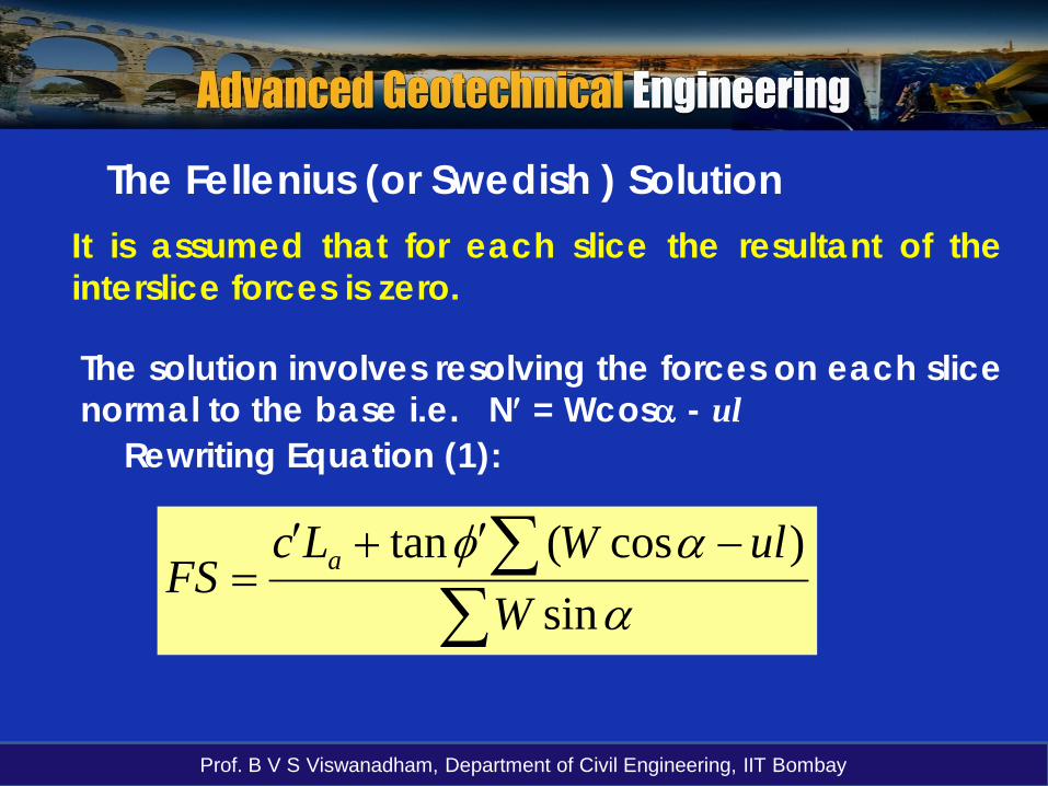
The Fellenius (or Swedish ) SolutionIt is assumed that for each slice the resultant of theinterslice forces is zero.
The solution involves resolving the forces on each slicenormal to the base i.e. N′ = Wcosα - ul
∑∑ −′+′
=α
αφsin
)cos(tanW
ulWLcFS a
Rewriting Equation (1):
Prof. B V S Viswanadham, Department of Civil Engineering, IIT Bombay
r
r
α4
A
CD
12
34
567
α1
α3
-α5
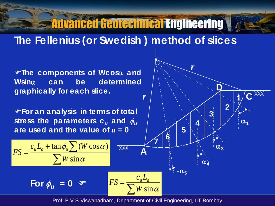
The Fellenius (or Swedish ) method of slices
The components of Wcosα andWsinα can be determinedgraphically for each slice.
For an analysis in terms of totalstress the parameters cu and φuare used and the value of u = 0
∑∑+
=α
αφsin
)cos(tanW
WLcFS uau
∑=
αsinWLcFS auFor φu = 0
Prof. B V S Viswanadham, Department of Civil Engineering, IIT Bombay
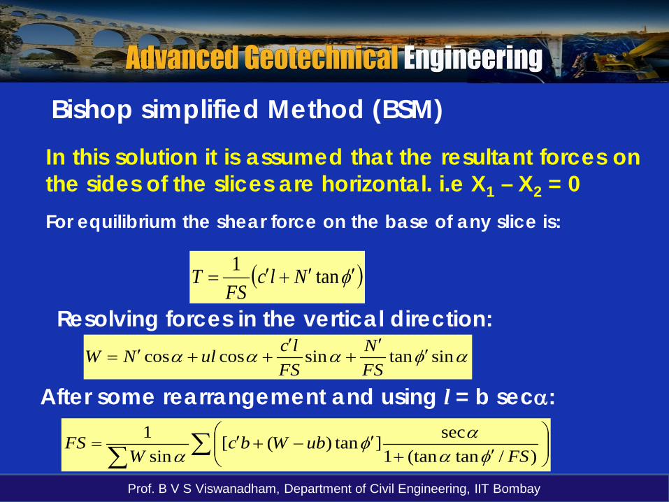
In this solution it is assumed that the resultant forces onthe sides of the slices are horizontal. i.e X1 – X2 = 0For equilibrium the shear force on the base of any slice is:
( )φ′′+′= tan1 NlcFS
T
Resolving forces in the vertical direction:αφααα sintansincoscos ′
′+
′++′=
FSN
FSlculNW
After some rearrangement and using l = b secα:
∑∑
′+
′−+′=)/tan(tan1
sec]tan)([sin
1FS
ubWbcW
FSφα
αφα
Bishop simplified Method (BSM)

Prof. B V S Viswanadham, Department of Civil Engineering, IIT Bombay
Bishop (1955) also showed how non-zero values of theresultant forces (X1-X2) could be introduced into theanalysis but refinement has only a marginal effect onthe factor of safety.
The pore water pressure can be related to the total fillpressure at any point by means of dimensionless porepressure ratio ru = u/γh .
For any slice, ru = u/W/b
∑∑
′+
′−+′=)/tan(tan1
sec]tan)1([sin
1FS
rWbcW
FS u φααφ
α
By rewriting:
Bishop simplified Method (BSM)

Prof. B V S Viswanadham, Department of Civil Engineering, IIT Bombay
Bishop simplified Method (BSM)Bishop’s simplified method (BSM) considers theinterslice normal forces but neglects the intersliceshear forces. It further satisfies vertical forceequilibrium to determine the effective base normalforce (N’).

Prof. B V S Viswanadham, Department of Civil Engineering, IIT Bombay
Janbu’s simplified methodJanbu’s simplified method (JSM) is based on acomposite slip surface (i.e. non-circular) and the FOSis determined by horizontal force equilibrium. As inBSM, the method considers interslice normalforces (E) but neglects the shear forces (T).