Embed Size (px)
Citation preview

� OV� HUADE HYDRAULICS
BEIJING HUADE
HYDRAULIC INDUSTRIAL
GROUP CO.LTD.
2-way cartridge valves-pressure functions
Cartridge valves type LC...
Control covers type LFA...
Size 16 to 100 up to 40 MPa up to 7000L/min
RE 81078/12.99
Replaces�
type LFA.DB...
type LC..DB...
The 2-way cartridge valves for pressure control functions are pilot
operated poppet or spool valves.The main component designed as a
cartridge valve (1) is inserted in a cavity bore standardised to DIN
24342 and is sealed by control cover (2).
The pilot valve (4) for either manual or electrical proportional pressure
control is integrated into the control cover (2) or mounted onto the control
cover as a pilot valve with interface connections to DIN 24 340 .
Pressure relief function�Pages 32 to 71�
The cartridge valve (1) for the pressure relief function (type LC .DB..
is a poppet valve without an area differential (no effective area at port
B). The pressure acting at port A is fed via the pilot oil supply orifice (5)
to the spring side (6) of the element. At pressures below the setting of
pilot valve (4) the forces on spool (3) are balanced and the spool
remains closed due to the spring force. On reaching the set pressure,
spool (3) opens and limits the pressure at port A in line with the
pressure-flow characteristics.
Pressure reducing function�Pages 69 to 84�
a) Normally open:
The cartridge valve for the pressure reducing function is a spool valve
without an area differential (no effective area at port B).The same
types of cover are used as pilot valves as are used for the pressure
relief functions (type LFA..D...).
The pressure acting at port A is fed to the spring side of the spool via
the pilot oil supply orifice. Below the performance limit and pressure
set at the pilot valve, the spool is pressure balanced and is held open
by the spring force, so that oil is free to flow from port B to port A.
On reaching the set pressure,the spool closes and reduces the
pressure at port A in line with the pressure-flow characteristics.
Pressure Reducing Valve
Normally open
eg.
type LFA..DB...
type LC..DR40...
K3787/6
Cartridge valve type LC .. DB
K3786/6
Control cover with manual
pressure adjustment,
type LFA ..DBW..
Function ,section,symbols

� PM�HUADE HYDRAULICS
Function, description
b) Normally closed:
For the pressure reducing function with a pressure reduc-
ing valve (type LFA..DR...) as the pilot valve are used.
The pilot oil is fed from port A via the pilot supply orifice
and the open pressure reducing pilot valve to side B.
The main spool opens and allows free flow from port A
to port B.On reaching the set pressure,the spool closes
and reduces the pressure at port B in line with the
pressure-flow characteristics.Possible excess pressures
occurring on the secondary side are led away to tank via
the third port of the pilot valve. By fitting a directional
valve, an addi-tional isolating function can also be at-
tained (type LFA..DRW...).
Pressure sequencing function
Control cover type LFA...DZ...
Control cover type LC...DB...
This function enables a pressure-dependent sequenc-
ing of a second system.
The required sequencing pressure is set by the pilot
valve which is integrated into the control cover.
The pilot oil supply may be either external (pilot oil port
X) or internal(from port A via pilot oil port X or Z2).
The spring chamber of the pilot control is drained at zero
pressure via ports Y or Z1 to tank.
Typical circuits
Example 1:
In the circuit shown, the system is fed by a high pressure
pump and a low pressure pump.The system pressure
pS acts externally from the high pressure side via the
pilot oil port X on the pilot valve which, on reaching the
set pressure,switches the low pressure side to give zero
pressure circulation.The check valve RV (not included
within the scope of supply) prevents the high pressure
system from flowing into the low pressure system which
is now at zero pressure.
When the pressure set at the pilot control spring is
reached, the pilot valve switches and unloads the spring
chamber of the main valve to tank. The main spools
opens and makes the connection from port A to B
possible.
In model LFA..DZW...,the required spool position may
be selected by means of an electrically operated pilot
valve (not included within the supply of control cover �
LFA..DZW...) in addition to the normal hydraulic control.
Pressure reducing
valve
Normlly closed
e.g�
Type LFA..DB..
Type LC..DB 40D6XB
e.g
Type LFA..DZ...6XB/...XY
Type LC..DB20D6XB
Example 1:
Circuit for the pressure
dependent unloading of
the low pressure system

� PN� HUADE HYDRAULICS
Installation cavity and porting pattern to DIN 24342 (Dimensions in mm)
Example 2:
With this circuit, oil is allowed to flow into
system 2 when the pressure in system 1 has
reached a pre-set value.The pilot oil supply is
internal from port A of the main valve.
Type LFA..DZ...6XB/...Y
Type LC..DB20D6XB
System 1
System 2
Size 16 25 32 40 50 63 80 100
øD1 32 45 60 75 90 120 145 180
øD2 16 25 32 40 50 63 80 100
øD3 16 25 32 40 50 63 80 100
(øD3)* 25 32 40 50 63 80 100 125
øD4 25 34 45 55 68 90 110 135
øD5 M8 M12 M16 M20 M20 M30 M24 M30
øD61) 4 6 8 10 10 12 16 20
øD7 4 6 6 6 8 8 10 10
H1 34 44 52 64 72 95 130 155
(H1*) 29.5 40.5 48 59 65.5 86.5 120 142
H2 56 72 85 105 122 155 205 245
H3 43 58 70 87 100 130 175�0.2 210�0.2
H4 20 25 35 45 45 65 50 63
H5 11 12 13 15 17 20 25 29
H6 2 2.5 2.5 3 3 4 5 5
H7 20 30 30 30 35 40 40 50
H8 2 2.5 2.5 3 4 4 5 5
H9 0.5 1 1.5 2.5 2.5 3 4.5 4.5
L1 65/80 85 102 125 140 180 250 300
L2 46 58 70 85 100 125 200 245
L3 23 29 35 42.5 50 62.5 - -
L4 25 33 41 50 58 75 - -
L5 10.5 16 17 23 30 38 - -
W 0.05 0.05 0.1 0.1 0.1 0.2 0.2 0.2
1)Max. dim.1 Depth of fit2 Reference dimension3 For diameters of port B other than � D3 or ( � D3*), the distancefrom the cover mounting surface to the centre of this hole must becalculated.4 Port B may be moved about the cental axis of port A. Care musthowever be taken to ensure that the fixing holes and control holes arenot damaged.5 Drilling for location pin
NS16...63 NS16 Note
Length L1(It is 80mm from X to Y via
the center of the hole)
NS80,100
Example 2:
(circuit for the pressure
dependent sequencing
of a 2nd system)

� PO�HUADE HYDRAULICS
Pressure relief function
Ordering details: pressure relief cartridge valves (without control cover)
Nominal size 16 = 16Nominal size 25 = 25Nominal size 32 = 32Nominal size 40 = 40Nominal size 50 = 50Nominal size 63 = 63Nominal size 80 = 80Nominal size 100 = 100
Cracking pressure approx. 0 MPa (without spring) =00Cracking pressure approx. 0.2 MPa =20Cracking pressure approx. 0.4 MPa =40**Cracking pressure 0.3 MPa only with NS16 for fitting a pilotoperated pressure relief valve type DBC . -5X/
Further detials in clear text
No code = Mineral oils
V = Phosphate ester
B= Technology of Beijing Huade Hydraulic
E = Poppet valve without orifice (standard)
D = Spool poppet valve without orifice (standard)
A = Poppet valve with orifice
B = Spool poppet valve with orifice
}Standard
6X= Series 60 to 69 (60 to 69: unchanged
installation and connection dimensions)
Symbols: cartridge valves (for versions see ordering details)
Poppet valve
LC...DB...E6X
Spool poppet valve with orifice
LC...DB...A6X
Spool poppet valve
LC...DB...D6X
Spool poppet valve with orifice
LC...DB...B6X
LC DB 6X B *
DB
D...
Corresponds to
the permissible
tank pressure of
the pilot valves
Technical data (for applications outside these parameters, please consult us!)
Pressure fluid Mineral oil for NBR seals or Phosphate ester for FPM seals
Pressure fluid temperature range � -20 to +80
Viscosity range mm2/s 2.8 to 380
2-way cartridge valves
Operating pressure at port A and B up to 42MPa
Size 16 25 32 40 50 63 80 100
Max. Flow�recommend � L/min
Poppet valve cartridge LC...DB..E 6X/.. LC..DB..A 6X/.. 250 400 600 1000 1600 2500 4500 7000
Spool valve cartridge LC...DB..D 6X/.. LC..DB..B 6X/.. 175 300 450 700 1400 1750 3200 4900
Control Cover
Max. operating pressure
Type LFA..DB.. ..DBW.. ..DBS.. ..DBU..
..DBE.. ..DBETR..
NS ..DBM.. ..DBEMTR..
Port16..100
16 ...32 40...63 80,100 40...63 80,100 16..63 80,100 16...100 16...100
...X 40.0 40.0 31.5 31.5 40 31.5 35.0
When controlling pressure zero pressure �up to 0.2 MPa�
X�YStatic
31.5 10.016.0(DC) 16.0(DC)
16.0 10.0 5.016.0(�)
16.0 10.0 31.5state 10.0(AC) 10.0(AC) 10.0(�)
Pop
pet v
alve
s�N
S6
Spo
ol v
alve
s�N
S6
Spo
ol v
alve
s�N
S6
Spo
ol v
alve
s�N
S 1
0
Pop
pet v
alve
s�N
S6
Pop
pet v
alve
s�N
S6
Spo
ol v
alve
s�N
S6
Spo
ol v
alve
s�N
S 1
0
DB
ET
DB
ET
R
�GG

� PP� HUADE HYDRAULICS
General notes on the ordering details for control covers
For functions, see selection table on page 35
Types of adjuster for pressure relief valves
1 = Rotary knob
2 = Hexagon with protective cap
3 = Locable rotary knob with scale(H-lock to auto-
motive industry standards)
4 = Rotary knob with scale, not lockable
Series
6X = Series 60 to 69
(unchanged instal lat ion and connect ion
dimensions)
B = Techology of Beijing Huade Hydraulic
Pressure ratings
Dependent on size and permissible working pres-
sure of the pilot valve. For further details see
ordering details for the control cover.
Pressure ratings�025 = 2.5 MPa
050 = 5.0 MPa
100 = 10.0 MPa
200 = 20.0 MPa
315 = 31.5 MPa
400 = 40.0 MPa
420 = 42.0 MPa
LFA A... B... *B6X
1 2 4 6 7 8 9 1053
�= available
DBmax
DB2DB1
Nominal sizeType Page
Con-
trol
type
Se-
riesNote
Pressure rating
for nominal sizes othersFulid
16 25 32 40 50 63 80 100
DB
DBW
DBS
DBWD
DBU2A
DBU2B
DBU3D
DBE
DBETR
DBEM
DBEMTR
47...49
50...54
50...54
55...57
58...61
62...66
67
68...71
6X=
Ser
ies
60 to
69
Tec
hnol
ogy
of B
eijin
g H
uade
Hyd
raul
ic
16...32 40...100
50
100
200
315
420
50
100
200
315
420
50
100
200
315
420
050,100
200,315
420
025,050
100,200
315,420
025,050
100,200
315,420
025,050
100,200
315,420
025,050
100,200
315
For
ord
erin
g de
tails
, see
pag
es g
ivin
g de
tails
of t
he
indi
vidu
al c
over
var
iatio
ns4
5
6
7
8
Pressure data for DB1, only required for types DBU2
and DBU3D
Pressure data for DB2, only required for types DBU3D
Ordering example for type DBU3D
.../315* A B 200 (DB max. /DB1/DB2)
*DB max. always first
The control covers are always fitted with a, optimised
on our test rig,standard orifice. Orifice details are
therefore not required in the type code. Deviating
operating conditions could make it necessary to match
the orifice size. The orifices are of the threaded type.
Orifice as shown within the main symbol
Su==_
^KKK
_KKK
� PQ�HUADE HYDRAULICS
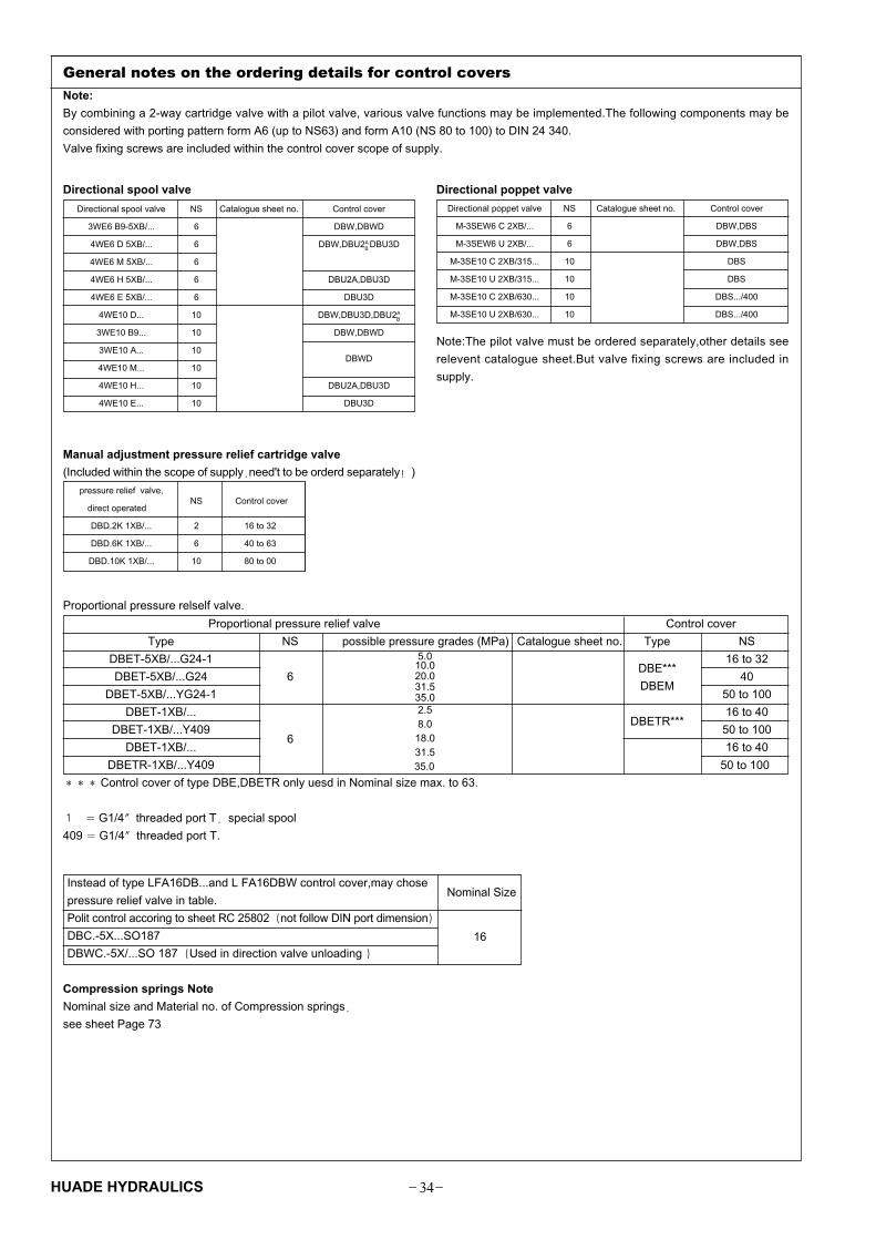
Directional spool valve NS Catalogue sheet no. Control cover
3WE6 B9-5XB/... 6 DBW,DBWD
4WE6 D 5XB/... 6 DBW,DBU2AB DBU3D
4WE6 M 5XB/... 6
4WE6 H 5XB/... 6 DBU2A,DBU3D
4WE6 E 5XB/... 6 DBU3D
4WE10 D... 10 DBW,DBU3D,DBU2AB
3WE10 B9... 10 DBW,DBWD
3WE10 A... 10DBWD
4WE10 M... 10
4WE10 H... 10 DBU2A,DBU3D
4WE10 E... 10 DBU3D
General notes on the ordering details for control covers
Note:
By combining a 2-way cartridge valve with a pilot valve, various valve functions may be implemented.The following components may be
considered with porting pattern form A6 (up to NS63) and form A10 (NS 80 to 100) to DIN 24 340.
Valve fixing screws are included within the control cover scope of supply.
Directional poppet valve NS Catalogue sheet no. Control cover
M-3SEW6 C 2XB/... 6 DBW,DBS
M-3SEW6 U 2XB/... 6 DBW,DBS
M-3SE10 C 2XB/315... 10 DBS
M-3SE10 U 2XB/315... 10 DBS
M-3SE10 C 2XB/630... 10 DBS.../400
M-3SE10 U 2XB/630... 10 DBS.../400
Directional spool valve Directional poppet valve
pressure relief valve,NS Control cover
direct operated
DBD.2K 1XB/... 2 16 to 32
DBD.6K 1XB/... 6 40 to 63
DBD.10K 1XB/... 10 80 to 00
Manual adjustment pressure relief cartridge valve
(Included within the scope of supply�need't to be orderd separately�)
Note:The pilot valve must be ordered separately,other details see
relevent catalogue sheet.But valve fixing screws are included in
supply.
Proportional pressure relief valve Control cover
Type NS possible pressure grades (MPa) Catalogue sheet no. Type NS
DBET-5XB/...G24-1 16 to 32
DBET-5XB/...G24 6DBE***
40
DBET-5XB/...YG24-1DBEM
50 to 100
DBET-1XB/... 16 to 40
DBET-1XB/...Y409DBETR***
50 to 100
DBET-1XB/...6
16 to 40
DBETR-1XB/...Y409
���Control cover of type DBE,DBETR only uesd in Nominal size max. to 63.
� � G1/4�threaded port T�special spool
409 � G1/4�threaded port T.
5.010.020.031.535.02.58.018.031.5
35.0
Instead of type LFA16DB...and L FA16DBW control cover,may chose Nominal Size
pressure relief valve in table.
Polit control accoring to sheet RC 25802�not follow DIN port dimension�
16DBC.-5X...SO187
DBWC.-5X/...SO 187�Used in direction valve unloading �
Compression springs Note
Nominal size and Material no. of Compression springs�
see sheet Page 73
Proportional pressure relself valve.
50 to 100

� PR� HUADE HYDRAULICS
Pilot control valves (selection table)
= available
Nom. size
Type Pilot control
valve
Manual pressure setting Symbols
DB
16to
32
40to
63
80to
100
Without directional valve
With directional valve 1
a a b b
a a 0 b b
A B
P T
A B
P T
Position "a" Position "b"
Position "a" Position "o" Position "b"
open DB function
DB function open
open DB function
DB function open
open DB function
DB function open
open DB function
DB function open
DB function closed
closed DB function
DBmax function
open
DB1 function
DB1 function DBmax function
DB2 function
open
DBmax function
DB1 function
open
open
DB1 Proportional
DB1 Proportional
2,3
4
5
6
-
7
8
9
3
DBW
DBS
DBWD
DBU2A
DBU2B
DBU3D
DBEDBETRDBEM
DBEMTR
Dire
ctio
nal v
alve
unl
oadi
ngIs
olat
ing
func
tion
2 pr
essu
re s
tage
s3
pres
sure
sta
ges
Pro
port
iona
l
valv
es
DBET-5XB/...DBETR-1XB/...DBET-5XB/...
DBETR-1XB/...
3WE6B9-...
M-3SEW6C...
4WE6D ...
M-3SEW6U...
3WE10B9 ...
4WE10D...
M-3SEW6C...
M-3SEW6U...
M-3SE10C./..
M-3SE10U./..
3WE6B9-...
3WE10B9-...
3WE6A-...
4WE6M...
3WE10A-...
4WE10M...
4WE6H...
4WE10H...
4WE6D...
4WE10D...
4WE6D...
4WE10D...
4WE6H...
4WE10H...
4WE6E...
4WE10E...
4WE6D...
4WE10D...
Open = bypass circuit
Closed = cartridge valve is hydraulically blocked
DB function = pressure relief function
Proportional pressure setting
Without max. pressure safety limitation
With max. pressure safety limitation

� PS�HUADE HYDRAULICS
Symbol overview (basic symbols), pressure relief function
Valid symboles are shown in the
following type descriptions!
1LFA...DBW.-/.. NS 16 to 100
LFA...DBW.-/.. NS 16 to 32 LFA...DB.-/.. NS 10 to 100
2 3
4 5 6LFA...DBS.-/..NS 40 to 100 LFA...DBWD.-/..NS 16 to 100 LFA...DBU 2A.-/..NS 16 to 100
see pages 47 to 49 see pages 50 to 51 see pages 50 to 54
see pages 50 to 54 see pages 55 to 57
see pages 58 to 6178 9LFA...DBU 3D.-/..NS 16 to 100
LFA...DBE(TR).-/..NS 16 to 63 LFA...DBEM(TR).-/..NS 16 to 100
see pages 62 to 66 see page 67 see pages 68 to 71

� PT� HUADE HYDRAULICS
Characteristic curves: (measured at v =41mm 2 /s and t = 50 �C)
Byp
ass
pres
sure
in M
Pa
Low
est s
etta
ble
pres
sure
in M
Pa
Byp
ass
pres
sure
in M
Pa
Low
est s
etta
ble
pres
sure
in
MP
a
The characteristic curves were measured with an external pilot oil drain at zero pressure. With an
internal pilot oil drain the inlet pressure is increased to the pressure being applied at port B.
DB
Man
ual p
ress
ure
adju
stm
ent,
type
LF
A16
DB
W...
6XB
/...
Ele
ctric
al p
ropo
rtio
nal p
ress
ure
adju
stm
ent,
type
LF
A16
DB
E...
6XB
/...
Low
est s
etta
ble
pres
sure
in M
Pa
Low
est s
etta
ble
pres
sure
in M
Pa
Inle
t pre
ssur
e in
MP
aIn
let p
ress
ure
in M
Pa
Inle
t pre
ssur
e in
MP
aIn
let p
ress
ure
in M
Pa
Flow in L/min Flow in L/min
Flow in L/min Flow in L/min
Flow in L/min Flow in L/min
Flow in L/min Flow in L/min
LC 16 DB...E 6 XB
LC 16 DB...D 6 XB
LC 16 DB...E 6 XB
LC 16 DB...D 6 XB
NS 16
.
..
.

� PU�HUADE HYDRAULICS
Characteristic curves� (measured at v =41mm 2 /s and t = 50 �C)
Byp
ass
pres
sure
in M
Pa
Low
est s
etta
ble
pres
sure
in
MP
a
Byp
ass
pres
sure
in M
Pa
Lo
we
st s
ett
ab
le p
ress
ure
in M
Pa
The characteristic curves were measured with an external pilot oil drain at zero pressure. With an internal
pilot oil drain the inlet pressure is increased to the pressure being applied at port B.
D
BM
anua
l pre
ssur
e ad
just
men
t,LF
A 2
5
D
BW
...6X
B/..
.
Low
est s
etta
ble
pres
sure
in M
Pa
Inle
t pre
ssur
e in
MP
aIn
let p
ress
ure
in M
Pa
Inle
t pre
ssur
e in
MP
aIn
let p
ress
ure
in M
Pa
Flow in L/min Flow in L/min
Flow in L/min Flow in L/min
Flow in L/min Flow in L/min
Flow in L/min Flow in L/min
LC 25 DB...E 6 X
LC 25 DB...D 6 X
LC 25 DB...E 6 X
LC 25 DB...D 6 X
Low
est s
etta
ble
pres
sure
in M
Pa
NS 25
Ele
ctric
al p
ropo
rtio
nal p
ress
ure
adju
stm
ent,
type
LF
A25
DB
E...
6XB
/...
.
..
.

� PV� HUADE HYDRAULICS
Characteristic curves� (measured at v =41mm 2 /s and t = 50 �C)
Byp
ass
pres
sure
in M
Pa
Low
est s
etta
ble
pres
sure
in
MP
a
The characteristic curves were measured with an external pilot oil drain at zero pressure. With an internal
pilot oil drain the inlet pressure is increased to the pressure being applied at port B.
D
BM
anua
l pre
ssur
e ad
just
men
t, ty
peLF
A 3
2 D
BW
...6X
B/..
.E
lect
rical
pro
port
iona
l pre
ssur
e ad
just
men
t, ty
pe L
FA
16D
BE
...6X
B/..
.
Low
est s
etta
ble
pres
sure
in M
Pa
Inle
t pre
ssur
e in
MP
aIn
let p
ress
ure
in M
Pa
Inle
t pre
ssur
e in
MP
aIn
let p
ress
ure
in M
Pa
Flow in L/min Flow in L/min
Flow in L/min Flow in L/min
Flow in L/min Flow in L/min
Flow in L/min Flow in L/min
LC 32 DB...E 6 XB
LC 32 DB...D 6 XB
LC 32 DB...E 6 XB
LC 32 DB...D 6 XB
Byp
ass
pres
sure
in M
Pa
Low
est s
etta
ble
pres
sure
in
MP
a
Low
est s
etta
ble
pres
sure
in M
Pa
NS 32
.
..
.

� QM�HUADE HYDRAULICS
Characteristic curves�(measured at v =41mm 2 /s and t = 50 �C)
The characteristic curves were measured with an external pilot oil drain at zero pressure. With an internal
pilot oil drain the inlet pressure is increased to the pressure being applied at port B.
D
BM
anua
l pre
ssur
e ad
just
men
t, ty
peLF
A 4
0 D
BW
...6X
B/..
.E
lect
rical
pro
port
iona
l pre
ssur
e ad
just
men
t, ty
pe L
FA
40D
BE
...6X
B/..
.
Inle
t pre
ssur
e in
MP
aIn
let p
ress
ure
in M
Pa
Inle
t pre
ssur
e in
MP
aIn
let p
ress
ure
in M
Pa
Flow in L/min Flow in L/min
Flow in L/min Flow in L/min
Flow in L/min Flow in L/min
Flow in L/min Flow in L/min
LC 40 DB...E 6 XB
LC 40 DB...D 6 XB
LC 40 DB...E 6 XB
LC 40 DB...D 6 XB
Byp
ass
pres
sure
in M
Pa
Low
est s
etta
ble
pres
sure
in
MP
a
Byp
ass
pres
sure
in M
Pa
Low
est s
etta
ble
pres
sure
in
MP
aLo
wes
t set
tabl
e pr
essu
rein
MP
aLo
wes
t set
tabl
e pr
essu
re in
MP
a
NS 40
.
..
.

� QN� HUADE HYDRAULICS
Characteristic curves� (measured at v =41mm 2 /s and t = 50 �C)
The characteristic curves were measured with an external pilot oil drain at zero pressure. With an internal
pilot oil drain the inlet pressure is increased to the pressure being applied at port B.
DB
Man
ual p
ress
ure
adju
stm
ent,
type
LFA
50
DB
W ...
6XB
/...
Ele
ctric
al p
ropo
rtio
nal p
ress
ure
adju
stm
ent,
type
LF
A50
DB
E...
6XB
/...
LC 50 DB...E 6 XB
LC 50 DB...D 6 XB
LC 50 DB...E 6 XB
LC 50 DB...D 6 XB
Byp
ass
pres
sure
in M
Pa
Low
est s
etta
ble
pres
sure
in
MP
a
Byp
ass
pres
sure
in M
Pa
Low
est s
etta
ble
pres
sure
in
MP
a
Flow in L/min Flow in L/min
Flow in L/minFlow in L/min
Flow in L/min
Flow in L/min Flow in L/min
Flow in L/min
Low
est s
etta
ble
pres
sure
in M
Pa
Low
est s
etta
ble
pres
sure
in M
Pa
Inle
t pre
ssur
e in
MP
aIn
let p
ress
ure
in M
Pa
Inle
t pre
ssur
e in
MP
aIn
let p
ress
ure
in M
Pa
NS 50
.
..
.

� QO�HUADE HYDRAULICS
Characteristic curves� (measured at v =41mm2/s and t = 50 �C)
The characteristic curves were measured with an external pilot oil drain at zero pressure. With an internal
pilot oil drain the inlet pressure is increased to the pressure being applied at port B.
D
BM
anua
l pre
ssur
e ad
just
men
t, ty
peLF
A 6
3 D
BW
...6X
B/..
.E
lect
rical
pro
port
iona
l pre
ssur
e ad
just
men
t, ty
pe L
FA
63D
BE
...6X
B/..
.
LC 63 DB...E 6 XB
LC 63 DB...D 6 XB
LC 63 DB...E 6 XB
LC 63 DB...D 6 XB
Byp
ass
pres
sure
in M
Pa
Low
est s
etta
ble
pres
sure
in
MP
a
Byp
ass
pres
sure
in M
Pa
Low
est s
etta
ble
pres
sure
in
MP
a
Flow in L/min Flow in L/min
Flow in L/minFlow in L/min
Flow in L/min Flow in L/min
Flow in L/minFlow in L/min
Inle
t pre
ssur
e in
MP
aIn
let p
ress
ure
in M
Pa
Inle
t pre
ssur
e in
MP
aIn
let p
ress
ure
in M
Pa
Low
est s
etta
ble
pres
sure
in M
Pa
Low
est s
etta
ble
pres
sure
in M
Pa
NS 63
.
..
.
� QP� HUADE HYDRAULICS
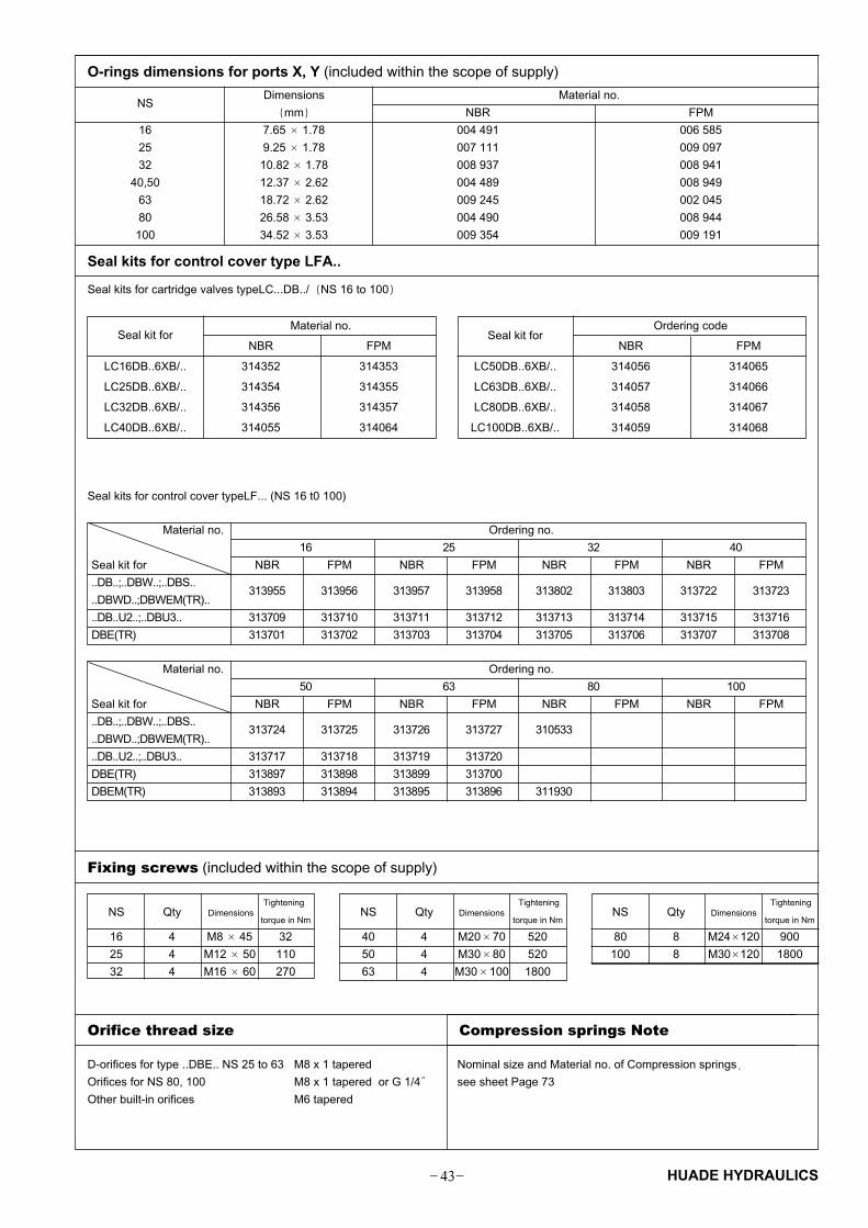
Fixing screws (included within the scope of supply)
NS Qty Dimensions Tightening
torque in Nm
16 4 M8 � 45 32
25 4 M12 � 50 110
32 4 M16 � 60 270
NS Qty Dimensions Tightening
torque in Nm
40 4 M20�70 520
50 4 M30�80 520
63 4 M30�100 1800
NS Qty Dimensions Tightening
torque in Nm
80 8 M24�120 900
100 8 M30�120 1800
Seal kits for control cover typeLF... (NS 16 t0 100)
Material no. Ordering no.
16 25 32 40
Seal kit for NBR FPM NBR FPM NBR FPM NBR FPM
..DB..;..DBW..;..DBS..313955 313956 313957 313958 313802 313803 313722 313723
..DBWD..;DBWEM(TR)..
..DB..U2..;..DBU3.. 313709 313710 313711 313712 313713 313714 313715 313716
DBE(TR) 313701 313702 313703 313704 313705 313706 313707 313708
Material no. Ordering no.
50 63 80 100
Seal kit for NBR FPM NBR FPM NBR FPM NBR FPM
..DB..;..DBW..;..DBS..313724 313725 313726 313727 310533
..DBWD..;DBWEM(TR)..
..DB..U2..;..DBU3.. 313717 313718 313719 313720
DBE(TR) 313897 313898 313899 313700
DBEM(TR) 313893 313894 313895 313896 311930
O-rings dimensions for ports X, Y (included within the scope of supply)
NSDimensions Material no.
�mm� NBR FPM
16 7.65 � 1.78 004 491 006 585
25 9.25 � 1.78 007 111 009 097
32 10.82 � 1.78 008 937 008 941
40,50 12.37 � 2.62 004 489 008 949
63 18.72 � 2.62 009 245 002 045
80 26.58 � 3.53 004 490 008 944
100 34.52 � 3.53 009 354 009 191
Seal kits for control cover type LFA..
Seal kits for cartridge valves typeLC...DB../�NS 16 to 100�
Seal kit forMaterial no.
NBR FPM
LC16DB..6XB/.. 314352 314353
LC25DB..6XB/.. 314354 314355
LC32DB..6XB/.. 314356 314357
LC40DB..6XB/.. 314055 314064
Seal kit forOrdering code
NBR FPM
LC50DB..6XB/.. 314056 314065
LC63DB..6XB/.. 314057 314066
LC80DB..6XB/.. 314058 314067
LC100DB..6XB/.. 314059 314068
D-orifices for type ..DBE.. NS 25 to 63 M8 x 1 tapered
Orifices for NS 80, 100 M8 x 1 tapered or G 1/4�
Other built-in orifices M6 tapered
Orifice thread size Compression springs Note
Nominal size and Material no. of Compression springs�
see sheet Page 73

� QQ�HUADE HYDRAULICS
Control cover with manual pressure adjustment
** Orifice - �
1) Orifice M6 tapered
NS 16 to 100
LFA DB 6X *B
1 3 5 102 4 6 9
Nominal size 16 = 16
Nominal size 25 = 25
Nominal size 32 = 32
Nominal size 40 = 40
Nominal size 50 = 50
Nominal size 63 = 63
Nominal size 80 = 80
Nominal size 100 = 100
Adjuster type
Rotary knob = 1
Hexagon with protective cap = 2
Lockable rotary knob with scale = 3
(H-lock to automotive industry standards)
Rotary knot with scale not lockable = 4
Further details in clear text
No code = Mineral oils
V = Phosphate ester
Pressure ratings
NS 16, 25 ,32 NS 40, 50, 63, 80, 100
050 = 5.0 MPa
100 = 10.0MPa
200 = 20.0 MPa
315 = 31.5 MPa
420 = 42.0 MPa
025 = 2.5 MPa
050 = 5.0 MPa
100 = 10.0 MPa
200 = 20.0 MPa
315 = 31.5 MPa
400 = 40.0 MPa
B = Technology of Beijing Huade Hydraulic
6X= Series 60 to 69 (60 to 69: unchanged
installation and connection dimensions)
1 Port X optionally as threaded
port
3 Locating pin
4 Adjuster type "2"
5 Adjuster type "1"
6 Adjuster type "3"
7 Adjuster type "4"
8 Space require to remove the key
9 Nameplate
10 Lock nut
11 Setting nut for max. pressure
with NS 32
LFA..DB.-7X/..
NS 16, 25, 32with NS
16, 25
NS 16...32
only with
version LFA 32 DB.
NS 16 25 32
X** 0.8 0.8 -
F** 1.0 1.0 1.2
D** - - 0.8
H1 40 40 50
H2 17 19 26
H3 15 24 28
H4 19 19 26
L1 65 85 100
L2 80 85 100
L3 36.5 49 56.5
L4 32.5 45.5 53

� QR� HUADE HYDRAULICS
Control cover with manual pressure adjustment (Dimensions in mm)
1 Port X optionally as threaded port
2 Port Y optionally as threaded port
3 Locating pin
4 Adjuster type "2"
5 Adjuster type "1"
6 Adjuster type "3"
7 Adjuster type "4"
8 Space required to remove key
9 Nameplate
10 Lock nut
LFA..DB.-../...
NS 40�50�63
NS 40�50
NS 63
** Orifice - φ1) Orifice M6 tapered
NS 40 50 63
F** 1.2 1.2 1.5
D** 1.0 1.2 1.5
D1 G1/4� G1/2� -
H1 60 68 82
H2 28 19.5 30
H3 32 34 50
H4 27 35 45.5
� L1 125 140 180
L2 69 80 -
L3 89 105 -
L4 76 84 -
L5 60 70 -
T1 12 14 -

� QS�HUADE HYDRAULICS
Control cover with manual pressure adjustment (Dimensions in mm)
LFA..DB.-../...
NS 80�100
NS 80�100
1 Port X optionally as threaded port
2 Port Y optionally as threaded port
3 Locating pin
4 Adjuster type "2"
5 Adjuster type "1"
6 Adjuster type "3"
7 Adjuster type "4"
8 Space required to remove key
9 Nameplate
10 Lock nut
** Orifice - �
1) Orifice G 1/4 tapered
NS 80 100
X** 3.0 3.0
F** 2.5 2.5
D2 250 300
H1 100 100
H2 38 38
H3 45 51
H4 58 58
L8 50 50

� QT� HUADE HYDRAULICS
Control cover with manual pressure adjustment, for electrical unloading
NS 16 to100
Pressure ratings
(take max. perm. pressure of pilot valve into account)
size 16�25�32
050=5.0MPa
100=10.0MPa
200=20.0MPa
315=31.5MPa
420=42.0MPa
size 40�50�63�80�100
025=2.5MPa
050=5.0MPa
100=10.0MPa
200=20.0MPa
315=31.5MPa
400=40.0MPa
NS 16 =16
NS 25 =25
NS 32 =32
NS 40 =40
Further details in clear text
No code = Mineral oils
V = Phosphate ester
NS 50 =50
NS 63 =63
NS 80 =80
NS 100 =100
B = Technology of Beijing Huade Hydraulic
6X = Series 60 to 69(60 to 69 unchanged installation and
connection dimentions)
Control cover type
For mounting a directional spool
or directional poppet valve (NS 16�25�32) =DBW
For mounting a directional poppet valve
(for NS 40, 50,63�80�100) =DBS
Adjuster type
Rotary knot = 1
Hexagon with protective cap = 2
Lockable rotary knob with scale = 3
(H-lock to automotive industry standards)
Rotary knot with scale not lockable = 4
LFA DB 6X *B
1 3 5 102 4 6 9
NS 16 to 32
Parts and dimensions see page 48
LFA..DBW.-../..
size 16�25�32
M-3 SEW 6 U 2XB/..
M-3 SEW 6 C 2XB/..
4 WE 6 D 5XB/..
3 WE 6 B9-5XB/..

� QU�HUADE HYDRAULICS
Control cover with manual pressure adjustment, for electrical unloading (Dimensions in mm)
1 Port X optionally as threaded port
2 Port Y optionally as threaded port
3 Locating pin
4 Adjuster type "2"
5 Adjuster type "1"
6 Adjuster type "3"
7 Adjuster type "4"
8 Space required to remove key
9 Nameplate
10 Lock nut11 Setting nut for max. pressure
** Orifice-ø
LFA..DBW.-../..
NS 40�50�63
NS X** F** D** P** H1 H2 H3 H4 H5 L1 L2 L3 L4 L5 L6 L7
16 0.8 1.0 0.8 1.0 40 17 15 19 28 65 80 36.5 32.5 35 7 17
25 0.8 1.0 0.8 1.0 40 19 24 19 28 85 85 49 45.5 36 8 27
32 0.8 1.2 1.0 1.0 50 26 28 26 37 100 100 56.5 53 57 30 34.5
NS 40�50�63
3 WE 6 B9-5XB/.. 4WE 6 D5XB/..
M-3 SEW 6 U 2XB/..
M-3 SEW 6 C 2XB/..
LFA..DBS.-../..
NS 40�50�63

� QV� HUADE HYDRAULICS
Control cover with manual pressure adjustment, for electrical unloading (Dimensions in mm)
1 Port X optionally as threaded port
2 Port Y optionally as threaded port
3 Locating pin
4 Adjuster type "2"
5 Adjuster type "1"
6 Adjuster type "3"
7 Adjuster type "4"
8 Space required to remove key
9 Nameplate
10 Lock nut
*LFA...DBS control cover dimensions ** Orifice-φ
NS 40�50
NS X** F** D** P** H1 H2 H2* H3 H4 H5 L1 L2 L3 L4 L5 L6 L7
40 0.8 1.2 1.0 1.2 60 46 17 32 27 40 125 62.5 69 76 68 43.5 47
50 0.8 1.2 1.2 1.5 68 51 19.5 34 35 50 140 67.5 80 84 74.5 51 54.5
Directional spool valve . WE 6....
LFA...DBW.../...LFA...DBS.../...
G1/
4�/1
2�S
ize
40�
G1/
2�/1
4�S
ize
50�
G1/4�/12�Size 40�
G1/2�/14�Size 50�
G1/4�/12�Size 40�
G1/2�/14�Size 50�

� RM�HUADE HYDRAULICS
Control cover with manual pressure adjustment, for electrical unloading (Dimensions in mm)
NS 63
NS A** F** D** P**
63 1.0 1.5 1.5 1.8
** Orifice-φ
1 Port X optionally as threaded port
2 Port Y optionally as threaded port
3 Locating pin
4 Adjuster type "2"
5 Adjuster type "1"
6 Adjuster type "3"
7 Adjuster type "4"
8 Space required to remove key
9 Nameplate
10 Lock nut
LFA...DBW.../...
Directional spool
valve . WE 6...

� RN� HUADE HYDRAULICS
Control cover with manual pressure adjustment, for electrical unloading (Dimensions in mm)
NS 80,100 3 WE 10 B9... M-3SE 10 U2XB/...
4 WE 10 D... M-3SE 10 C2XB/...
Directional poppet valve
M-3 S E10..2XB/...
Directional
spool valve
WE 10...
1 Port X optionally as threaded port
2 Port Y optionally as threaded port
3 Locating pin
4 Adjuster type "2"
5 Adjuster type "1"
6 Adjuster type "3"
7 Adjuster type "4"
8 Space required to remove key
9 Nameplate
10 Lock nut
** Orifice-ø
NS 80 100
A** 1.2 1.5
B** 3.0 3.0
X** 3.0 3.0
F** 2.5 2.5
P** 3.5 3.5
D2 250 300
H1 100 100
H2 30 30
H3 45 51
H4 52 52
L8 75 85
Type LFA..DBW.-../... Type LFA...DBS.-../...

� RO�HUADE HYDRAULICS
Control cover with manual pressure adjustment, for isolation functions (Dimensions in mm)
NS 16 to 100
LFA DBWD 6X �B
1 3 5 102 4 6 9
Pressure ratings
(take max. perm. pressure of pilot valve into account)
NS 16�25�32
050=5.0MPa
100=10.0MPa
200=20.0MPa
315=31.5MPa
420=42.0MPa
NS 40�50�63�80�100
025=2.5MPa
050=5.0MPa
100=10.0MPa
200=20.0MPa
315=31.5MPa
400=40.0MPa
NS 16 =16
NS 25 =25
NS 32 =32
NS 40 =40
NS 50 =50
NS 63 =63
NS 80 =80
NS 100=100
Series 60 to 69 = 6X(60 to 69 unchanged installation
and connection dimentions)
Adjuster type
Rotary knob = 1
Hexagon with protective cap = 2
Lockable rotary knob with scale = 3
(H-lock to automotive industry standards)
Rotary knob with scale not lockable = 4
Technology of Beijing Huade Hydraulic = B
Further details in clear text
No code = Mineral oils
V = Phosphate ester
3 WE 6 A5XB/....
4WE 6 M5XB/
3WE 6 B9-5XB/...
LFA...DBWD.-...
NS 16
LFA...DBWD.-...
NS 25,32
3WE 6 B9-5XB/...3 WE 10 A...
3 WE 10 B9...
4 WE 10M....
LFA...DBWD.-.../...
NS 40�50�63
LFA...DBWD.-6XB/...
NS 80�100

� RP� HUADE HYDRAULICS
Control cover with manual pressure adjustment, for isolation functions (Dimensions in mm)
NS 16 to 32
1 Port X optionally as threaded port
2 Port Y optionally as threaded port
3 Locating pin
4 Adjuster type "2"
5 Adjuster type "1"
6 Adjuster type "3"
7 Adjuster type "4"
8 Space required to remove key
9 Nameplate
10 Lock nut
11 Setting nut for max. pressure
Dimensions see page 54
not suitable for
NS 16
NS 40�50
Directional spool valve . WE 6...
Directional spool valve . WE 6...

� RQ�HUADE HYDRAULICS
Control cover with manual pressure adjustment , for isolation functions (Dimensions in mm)
** Orifice-φ
NS 16 25 32 40 50 63 80 100
B** 1.0 1.0 1.0 1.2 1.5 1.8 3.5 3.5
X** 0.8 0.8 0.8 - - - 3.0 3.0
F** 1.0 1.0 1.2 1.2 1.2 1.5 2.5 2.5
D** - - - 1.0 1.2 1.5 - -
D1 - - - G1/4� G1/2� - - -
D2 - - - - - - 250 300
H1 40 40 50 60 68 82 100 100
H2 - 19 26 46 50 55 67 67
H3 15 24 28 32 34 50 45 51
H4 19 19 26 27 35 45 58 58
H5 28 28 37 16 20 - - -
L1 65 85 100 � � � � �
� L1 - - - 125 140 180 - -
L2 80 85 100 - - - - -
L3 - 49 56.5 62.5 70 - - -
L4 32.5 45.5 53 76 84 - - -
L5 35 36 57 68 75 - - -
L6 7 8 30 43.5 51 - - -
L7 17 27 34.5 47 54.5 - - -
L8 - - - - - - 75 85
T1 - - - 12 14 - - -
NS 63
Directional spool
valve . WE 6...
Directional spool
valve . WE 10...
1 Port X optionally as threaded port
2 Port Y optionally as threaded port
3 Locating pin
4 Adjuster type "2"
5 Adjuster type "1"
6 Adjuster type "3"
7 Adjuster type "4"
8 Space required to remove key
9 Nameplate
10 Lock nut
NS 80,100

� RR� HUADE HYDRAULICS
Control cover with 2 manual pressure adjustments, electrically selectable
NS 16 to 100
Adjuster type
Rotary knob = 1
Hexagon with protective cap = 2
Lockable rotary knob with scale = 3
(H-lock to automotive industry standards)
Rotary knot with scale not lockable = 4
Further details in clear text
No code = Mineral oils
V = Phosphate ester
B = Technology of Beijing Huade Hydraulic
6X = Series 60 to 69 (60 to 69 unchanged installation and
connection dimentions)
1 3 5 102 4 6 9
LFA �6X B
NS 16 =16
NS 25 =25
NS 32 =32
NS 40 =40
NS 50 =50
NS 63 =63
NS 80 =80
NS 100=100
Control cover type
De-energised - DB1 (4 WE.. D)= DBU2A
De-energised - open (4 WE.. H)
De-energised - DB max. (4 WE.. D) = DBU2B
(see symbols) 050=5.0MPa
100=10.0MPa
200=20.0MPa
315=31.5MPa
420=42.0MPa
025=2.5MPa050=5.0MPa100=10.0MPa200=20.0MPa315=31.5MPa400=40.0MPa
Pressure ratings
(take max. perm. pressure of pilot valve into account)
Size 16�25�32 Size 40�50�63�80�100
4 WE 6 H 5XB/....
4 WE 6 D 5XB/....
4 WE 6 H 5XB/....
4 WE 6 D 5XB/....
LFA..DBU 2A.-../...
Size 16 to 32
LFA..DBU 2B.-../...
Size 40 to 63
LFA..DBU 2A.-../...
Size 40 to 63
LFA..DBU 2B.-../...
Size 16 to 32
4 WE 10H../....
4 WE 10D../....
LFA..DBU 2A.-../...
Size 80�100
LFA..DBU 2A.-../...
Size 80�100
�
A
DBmax DB1

� RS�HUADE HYDRAULICS
Control cover with 2 manual pressure adjustment, electrical selectable (Dimensions in mm)
NS 16 to 32
** Orifice-φNS X** F** D** P** H1 H2 H3 H4 H5 L1 L2 L3 L4 L5 L6 L7
16 0.8 1.0 0.8 1.0 40 17 15 19 28 65 80 36.5 32.5 35 7 17
25 0.8 1.0 0.8 1.0 40 19 24 19 28 85 85 49 45.5 36 8 27
32 0.8 1.2 1.0 1.0 50 26 28 26 37 100 100 56.5 53 57 30 34.5
Directional spool valve . WE 6....
1 Port X optionally as threaded port
2 Port Y optionally as threaded port
3 Locating pin
4 Adjuster type "2"
5 Adjuster type "1"
6 Adjuster type "3"
7 Adjuster type "4"
8 Space required to remove key
9 Nameplate
10 Lock nut
11 Setting nut for max. pressure
12 Plug M6 tapered for ..DBU 2A..
13 Plug M6 tapered for ..DBU 2B..

� RT� HUADE HYDRAULICS
Control cover with 2 manual pressure adjustments, electrically selectable (Dimensions in mm)
NS 40�50
** Orifice-φNS F** D** P** D1 H1 H2 H3 H4 H5 � L1 L3 L4 L5 L6 L7 T1
40 1.2 1.0 1.2 G1/4� 60 17 32 27 40 125 69 76 68 43.5 47 12
50 1.2 1.2 1.5 G1/2� 68 19.5 34 35 50 140 80 84 74.5 51 54.5 14
63 1.5 1.5 1.8 - 82 55 50 45 - 180 - - - - - -
1 Port X optionally as threaded port
2 Port Y optionally as threaded port
3 Locating pin
4 Adjuster type "2"
5 Adjuster type "1"
6 Adjuster type "3"
7 Adjuster type "4"
8 Space required to remove key
9 Nameplate
10 Lock nut
11 Setting nut for max. pressure
12 Plug M6 tapered for ..DBU 2A..
13 Plug M6 tapered for ..DBU 2B..
NS 63
Directional spool valve . 4WE 6... Directional spool valve . 4WE 6...

� RU�HUADE HYDRAULICS
Control cover with manual pressure adjustment (Dimensions in mm)
NS 80�100
1 Port X optionally as threaded port
2 Port Y optionally as threaded port
3 Locating pin
4 Adjuster type "2"
5 Adjuster type "1"
6 Adjuster type "3"
7 Adjuster type "4"
8 Space required to remove key
9 Nameplate
10 Lock nut
12 Plug M6 tapered for ..DBU 2A..
13 Plug M6 tapered for ..DBU 2B..
** Orifice-φNS X** F** P** D2 H1 H2 H3 H4 L8
80 3.0 2.5 3.5 250 100 30 45 52 75
100 3.0 2.5 3.5 300 100 30 51 52 85
Directional spool
valve . 4WE 10...

� RV� HUADE HYDRAULICS
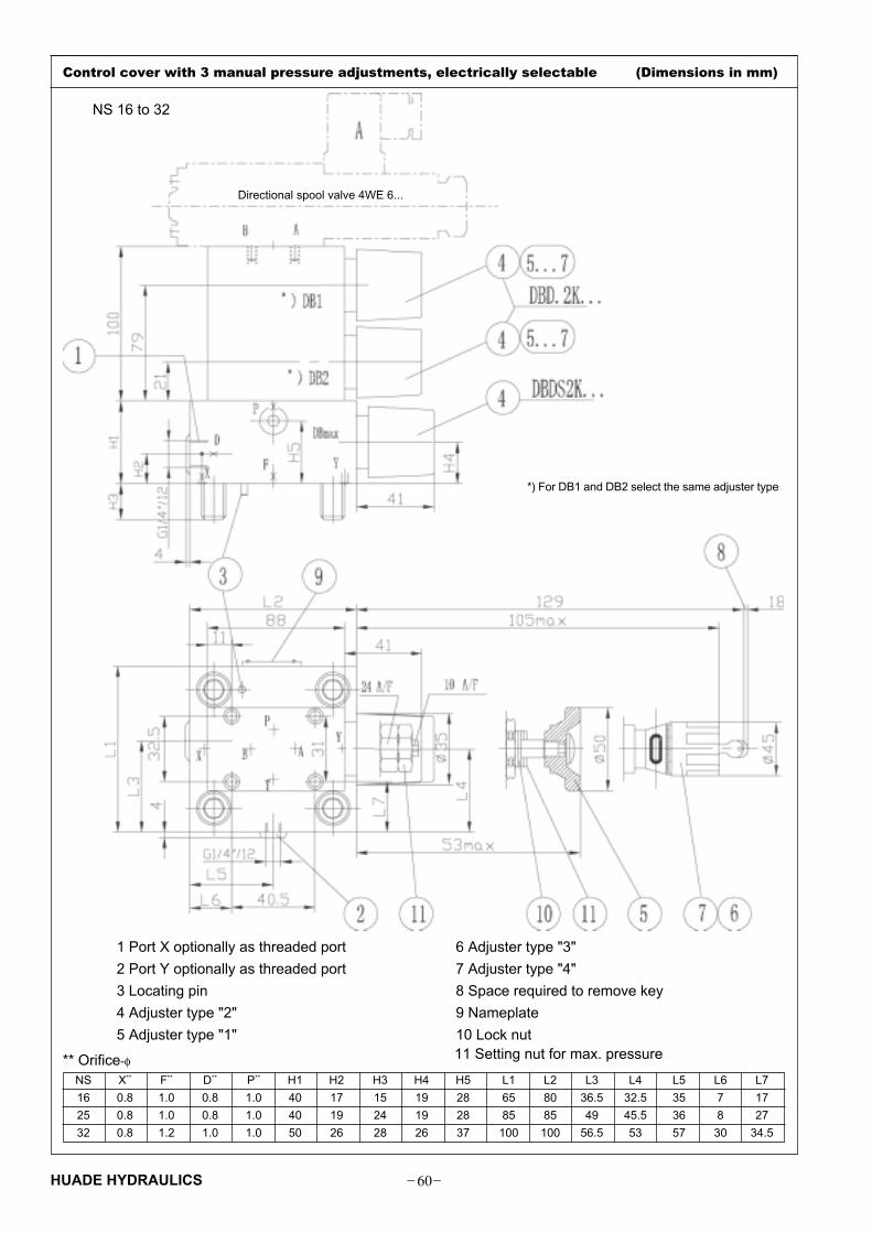
Control cover with 3 manual pressure adjustments, electrically selectable
NS 16 to 100
1 3 5 102 4 6 8
LFA
7 9
DBU3D B �6X B...A...
DBmax
DB2DB1 Further details in clear text
No code = Mineral oils
V = Phosphate ester
NS 16 =16
NS 25 =25
NS 32 =32
NS 40 =40
NS 50 =50
NS 63 =63
NS 80 =80
NS 100 =100
Adjuster type(detail only for DB1 or DB2)*
Rotary knob = 1
Hexagon with protective cap = 2
Lockable rotary knob with scale = 3
(H-lock to automotive industry standards)
Rotary knot with scale not lockable = 4
NS 16�25�32
050=5.0MPa
100=10.0MPa
200=20.0MPa
315=31.5MPa
420=42.0MPa
NS 40�50�63�80�100
025=2.5MPa
050=5.0MPa
100=10.0MPa
200=20.0MPa
315=31.5MPa
400=40.0MPa
Pressure ratings
(take max. perm. pressure of pilot valveinto account)
Series 60 to 69 = 6X
(60 to 69 unchanged installation and connection dimentions)
Technology of Beijing Huade Hydraulic = B
*) For DB1 and DB2 select the same adjuster type
4 WE 6 H 5XB/....
4 WE 6 E 5XB/....
4 WE 6 D 5XB/....
4 WE 10 H.../...
4 WE 10 E .../...
4 WE 10 D .../...
LFA..DBU 3D.-../...
Size 16�25�32
LFA..DBU 3D.-../...
Size 80�100
LFA..DBU 3D.-../...
Size 40�50�63
� SM�HUADE HYDRAULICS
Control cover with 3 manual pressure adjustments, electrically selectable (Dimensions in mm)
** Orifice-φNS X** F** D** P** H1 H2 H3 H4 H5 L1 L2 L3 L4 L5 L6 L7
16 0.8 1.0 0.8 1.0 40 17 15 19 28 65 80 36.5 32.5 35 7 17
25 0.8 1.0 0.8 1.0 40 19 24 19 28 85 85 49 45.5 36 8 27
32 0.8 1.2 1.0 1.0 50 26 28 26 37 100 100 56.5 53 57 30 34.5
1 Port X optionally as threaded port
2 Port Y optionally as threaded port
3 Locating pin
4 Adjuster type "2"
5 Adjuster type "1"
6 Adjuster type "3"
7 Adjuster type "4"
8 Space required to remove key
9 Nameplate
10 Lock nut 11 Setting nut for max. pressure
NS 16 to 32
Directional spool valve 4WE 6...
*) For DB1 and DB2 select the same adjuster type

� SN� HUADE HYDRAULICS
Control cover with 3 manual pressure adjustments, electrically selectable
** Orifice-φNS F** D** P** D1 H1 H2 H3 H4 H5 � L1 L3 L4 L5 L6 L7 T1
40 1.2 1.0 1.2 G1/4� 60 17 32 27 40 125 69 76 68 43.5 47 12
50 1.2 1.2 1.5 G1/2� 68 19.5 34 35 50 140 80 84 74.5 51 54.5 14
1 Port X optionally as threaded port
2 Port Y optionally as threaded port
3 Locating pin
4 Adjuster type "2"
5 Adjuster type "1"
6 Adjuster type "3"
7 Adjuster type "4"
8 Space required to remove key
9 Nameplate
10 Lock nut
NS 40�50
Directional spool valve . 4WE 6.....
*) For DB1 and DB2 select the
same adjuster type

� SO�HUADE HYDRAULICS
Control cover with 3 manual pressure adjustments, electrically selectable (Dimensions in mm)
NS 63
1 Port X optionally as threaded port
2 Port Y optionally as threaded port
3 Locating pin
4 Adjuster type "2"
5 Adjuster type "1"
6 Adjuster type "3"
7 Adjuster type "4"
8 Space required to remove key
9 Nameplate
10 Lock nut
*) For DB1 and DB2 select the
same adjuster type
** Orifice-φNS 63
F** 1.5
D** 1.5
P** 1.8Directional spool valve . 4WE 6.....

� SP� HUADE HYDRAULICS
Control cover with 3 manual pressure adjustments, electrically selectable (Dimensions in mm)
NS 80�100
1 Port X optionally as threaded port
2 Port Y optionally as threaded port
3 Locating pin
4 Adjuster type "2"
5 Adjuster type "1"
6 Adjuster type "3"
7 Adjuster type "4"
8 Space required to remove key
9 Nameplate
10 Lock nut
*) For DB1 and DB2 select the
same adjuster type
** Orifice-φNS X** F** P** D2 H1 H2 H3 H4 L8
80 3.0 2.5 3.5 250 100 30 45 52 75
100 3.0 2.5 3.5 300 100 30 51 52 85
Directional spool valve .
4WE 10...

� SQ�HUADE HYDRAULICS
** Orifice-φNS 16 25 32 40 50 63B** - - - - 0.8 0.8D** 0.8 0.8 0.8 1.0 2.0 2.0
X** 0.8 - - - - -F** - 0.8 1.0 1.2 1.2 1.5P** 1.0 1.0 1.0 1.5 1.0 1.0
D1 G1/4� G1/4�G1/4� G1/2� G1/2�G1/2�H1 40 40 50 60 68 82H2 17 19 26 30 32 30
H3 15 24 28 32 34 50H4 20 19 26 30 32 40L1 65 85 100 125 140 180
L2 80 85 100 125 140 180L3 36.5 49 56.5 72 80 100L4 23.5 36 43.5 53 50 80
L5 7 22.5 30 43.5 51 71L6 17 27 34.5 47 54.5 74.5T1 12 12 12 14 14 14
Control cover for electrical-proportional pressure adjustment, without maximum pressure limitation
NS16 to 63
Further details in clear text
No code = Mineral oils
V = Phosphate ester
B = Technology of Beijing Huade Hydraulic
6X= Series 60 to 69
(60 to 69 unchanged installation and connection dimentions)
NS 16 =16
NS 25 =25
NS 32 =32
NS 40 =40
NS 50 =50
NS 63 =63
For mounting a proportional pressure relief valve
without electrical feedback = DBE
with electrical feedback = DBETR
1 3 5 102 9
LFA B �6X
1 Port X optionally as threaded port
2 Port Y optionally as threaded port
3 Locating pin
9 Nameplate
14 Proportional pressure relief valve
type DBET-5XB/...see page 35
15 Proportional pressure relief valve
with feedback
type DBETR-1XB/...�see page 35�
zero
pressure
Return to
tank at zero
pressure
LFA...DBE.../.. LFA...DBETR.../..
NS 16LFA...DBE.../.. LFA...DBETR.../..
NS 25�32�40
LFA...DBE.../.. LFA...DBETR.../..
NS 50�63
NS 50�63
16 Pressure relief valve NS 6
(is included within the scope of
supply)
NS 16...40
not NS16
NS 40�50�63
NS 16 25 32
only NS 16
Directional spool valve . WE 6...

� SR� HUADE HYDRAULICS
Control cover for electrical-proportional pressure adjustment, with maximum pressure limitation
NS 16 to 1001 3 5 102 6 9
Further details in clear text
No code = Mineral oils
V = Phosphate ester
NS 16=16
NS 25=25
NS 32=32
NS 40=40
NS 50 =50
NS 63 =63
NS 80 =80
NS 100=100
NS 16�25�32
050=5.0MPa
100=10.0MPa
200=20.0MPa
315=31.5MPa
420=42.0MPa
NS 40�50�63�80�100
025=2.5MPa
050=5.0MPa
100=10.0MPa
200=20.0MPa
315=31.5MPa
400=40.0MPa
Pressure ratings
(take max. perm. pressure of pilot valve into account)
Series 60 to 69 = 6X
(60 to 69 unchanged installation and connection dimentions)
Technology of Beijing Huade Hydraulic
LFA 6X B �
For mounting a proportional pressure relief valve
without electrical feedback = DBE
with electrical feedback = DBETR
zero
pressure
LFA...DBEM.../..
LFA...DBEMTR.../..
NS 16�25�32
LFA...DBEM.../..
LFA...DBEMTR.../..
NS 40
LFA...DBEM.../..
LFA...DBEMTR.../..
NS 50�63
LFA...DBEM.../..
LFA...DBEMTR.../..
NS 80,100
= B

� SS�HUADE HYDRAULICS
Control cover with 3 manual pressure adjustments, electrically selectable (Dimensions in mm)
NS 16 to 32
1)G 1/4 threaded port T,
special poppet
Ports T and Y - zero pressure
1 Port X optionally as threaded port
2 Port Y optionally as threaded port
3 Locating pin
4 Adjuster type "2"
9 Nameplate
10 Lock nut
** Orifice-φNS X** F** D** P** H1 H2 H3 H4 H5 L1 L2 L3 L4 L5 L6 L7
16 0.8 1.0 0.8 1.0 40 17 15 19 28 65 80 36.5 32.5 7 17 35
25 0.8 1.0 0.8 1.0 40 19 24 19 28 85 85 49 45.5 8 27 36
32 0.8 1.2 1.0 1.0 50 26 28 26 37 100 100 56.5 53 30 34.5 57
11 The Max.settable pressure
14 Proportional pressure relief valve
type DBET-5XB/...see page 34
15 Proportional pressure relief valve with feed-
back
type DBETR-1XB/...�see page 34�

� ST� HUADE HYDRAULICS
Control cover for electrical-proportional pressure adjustment, with maximum pressure limitation
NS 40
1 Port X optionally as threaded port
2 Port Y optionally as threaded port
3 Locating pin
4 Adjuster type "2"
9 Nameplate
10 Lock nut
14 Proportional pressure relief valve
type DBET-5XB/G24 (NS 40)
type DBET-5XB/Y G24-1 1) (NS 50)
(see page 34)
15 Proportional pressure relief valve with feed-
back
type DBETR-1XB/...�see page 34�
type DBETR-1XB/...409 2) (NS 50)
16 Pressure relief valve NS 6
(is included within the scope of supply)
1� G 1/4� threaded port T,
special poppet2� 409 = G 1/4� threaded port T,
NS 50
** Orifice-φNS 40 50
B** - 0.8
F** 1.2 1.2
D** 1.0 2.0
P** 1.5 1.0
H1 60 68
H2 20 19.5
H3 32 34
H4 27 35
H5 40 50
� L1 125 140
L3 68 90
L4 76 84
L5 43.5 51
L6 47 54.5
L7 68 74.5

� SU�HUADE HYDRAULICS
Control cover with 3 manual pressure adjustments, electrically selectable (Dimensions in mm)
NS 63
** Orifice-ø
NS B** X** F** D** P** H1 H2 H3 H4 D2 � L1 L8
63 0.8 - 1.5 2.0 1.0 82 55 50 45 - 180 -
80 0.8 3.0 2.5 0.8 1.0 100 30 45 52 250 - 75
100 0.8 3.5 3.0 0.8 1.0 100 30 51 52 300 - 85
NS 80,100
1 Port X optionally as threaded port
2 Port Y optionally as threaded port
3 Locating pin
4 Adjuster type "2"
9 Nameplate
10 Lock nut
14 Proportional pressure relief valve
type DBET-5XB/G24 (NS 40)
type DBET-5XB/Y G24-1 3) (NS 50)
(see page 34)
15 Proportional pressure relief valve with feed-
back
type DBETR-1XB/...(NS 40)�see page 34�
type DBETR-1XB/...409 2) (NS 50)
16 Pressure relief valve NS 6
(included within the scope of supply)
1� G 1/4� threaded port T,
special poppet2�409 = G 1/4� threaded
port T