Embed Size (px)
Citation preview
1
01 February 2013
1
(2) Structural systems: principles, load bearing behaviour, application
Course Design Principles for Precast Concrete Structures South Africa, January 2013
Joost Walraven
01 February 2013 2
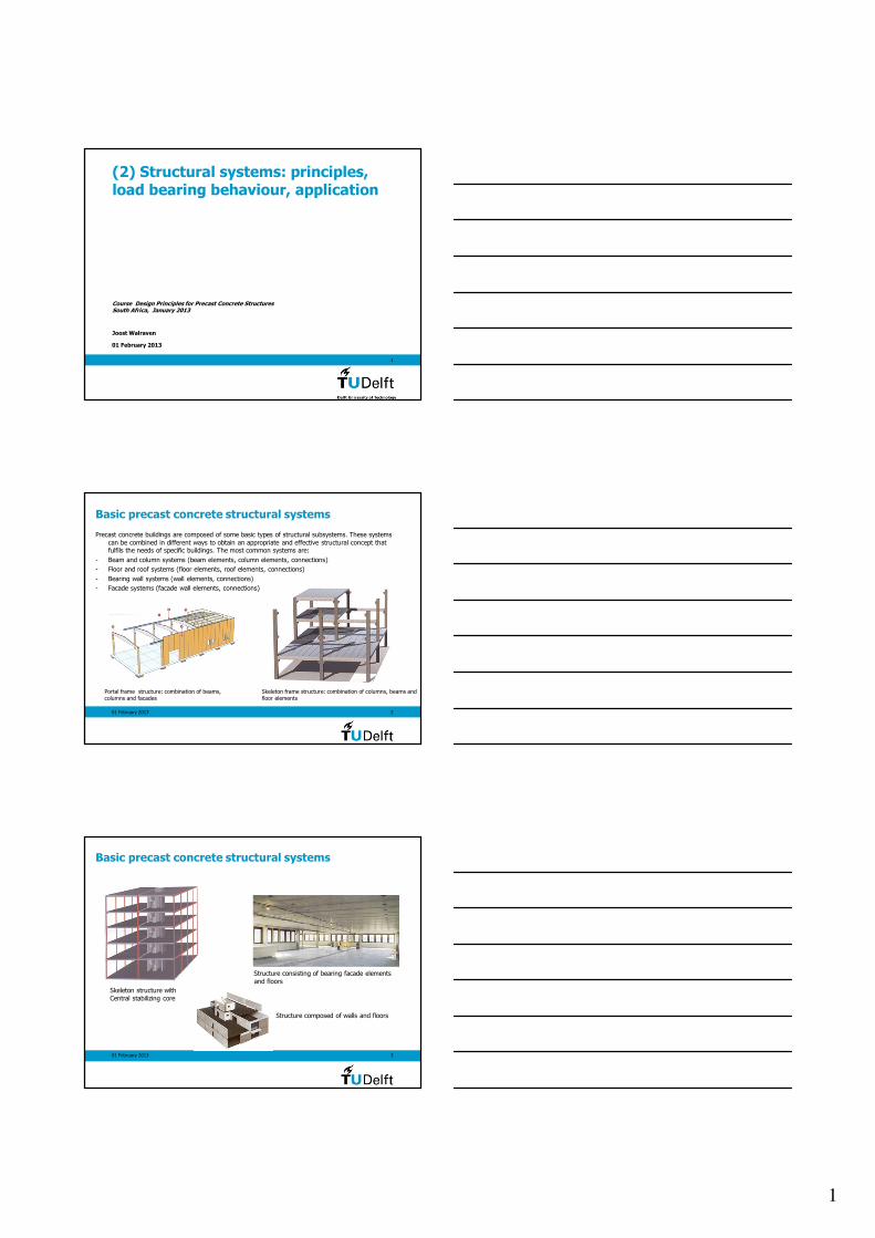
Basic precast concrete structural systems
Precast concrete buildings are composed of some basic types of structural subsystems. These systems
can be combined in different ways to obtain an appropriate and effective structural concept that fulfils the needs of specific buildings. The most common systems are:
- Beam and column systems (beam elements, column elements, connections)
- Floor and roof systems (floor elements, roof elements, connections)
- Bearing wall systems (wall elements, connections)
- Facade systems (facade wall elements, connections)
Portal frame structure: combination of beams, columns and facades
Skeleton frame structure: combination of columns, beams and floor elements
01 February 2013 3
Structure consisting of bearing facade elements
and floors
Basic precast concrete structural systems
Skeleton structure with
Central stabilizing core
Structure composed of walls and floors
2
01 February 2013 4
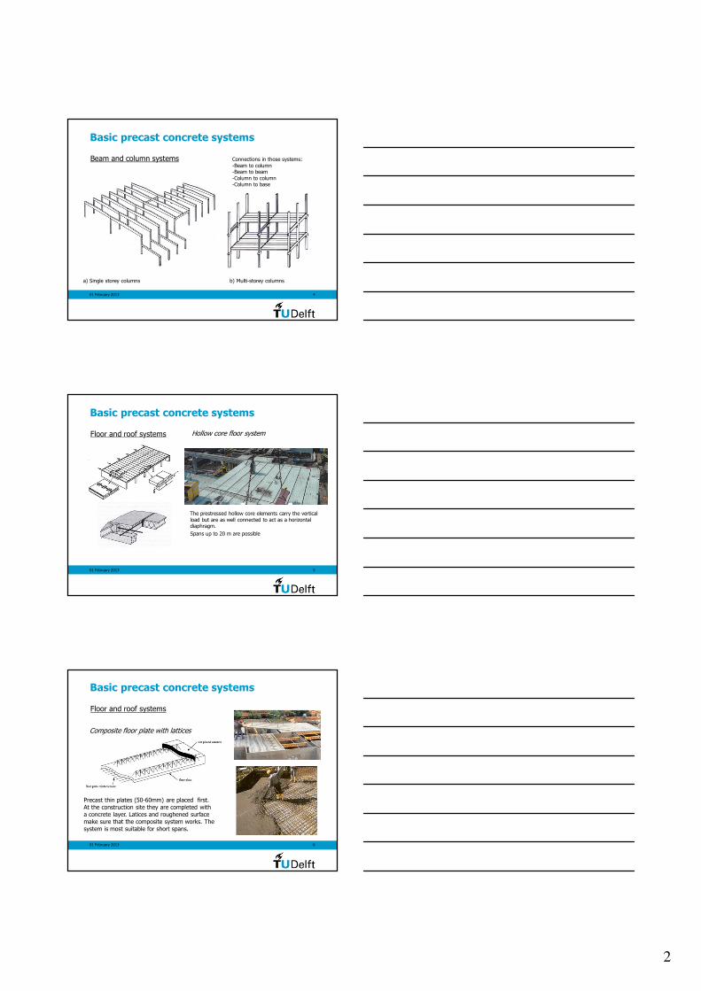
Basic precast concrete systems
a) Single storey columns b) Multi-storey columns
Beam and column systems Connections in those systems:
-Beam to column-Beam to beam
-Column to column-Column to base
01 February 2013 5
Basic precast concrete systems
The prestressed hollow core elements carry the vertical
load but are as well connected to act as a horizontal diaphragm.
Spans up to 20 m are possible
Floor and roof systems Hollow core floor system
01 February 2013 6
Basic precast concrete systems
Composite floor plate with lattices
Precast thin plates (50-60mm) are placed first.
At the construction site they are completed with
a concrete layer. Latices and roughened surface
make sure that the composite system works. The
system is most suitable for short spans.
Floor and roof systems
3
01 February 2013 7
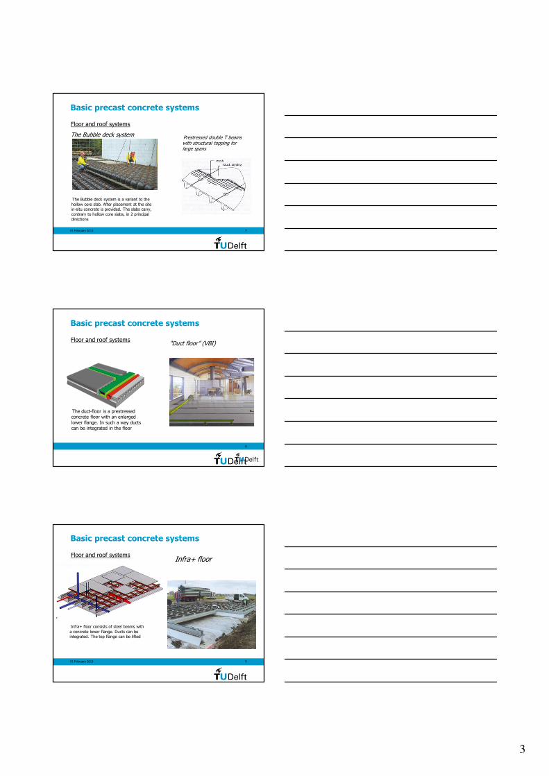
Prestressed double T beams with structural topping for large spans
Basic precast concrete systems
The Bubble deck system is a variant to the
hollow core slab. After placement at the site in-situ concrete is provided. The slabs carry,
contrary to hollow core slabs, in 2 principal
directions
The Bubble deck system
Floor and roof systems
8
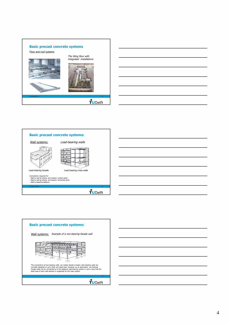
“Duct floor” (VBI)
Basic precast concrete systems
The duct-floor is a prestressed
concrete floor with an enlarged
lower flange. In such a way ducts
can be integrated in the floor
Floor and roof systems
01 February 2013 9
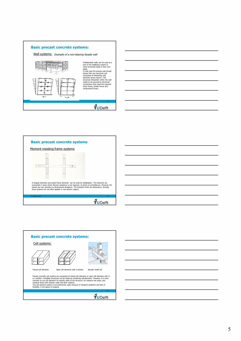
Basic precast concrete systems
Infra+ floor consists of steel beams with
a concrete lower flange. Ducts can beintegrated. The top flange can be lifted
Infra+ floorFloor and roof systems
4
01 February 2013 10
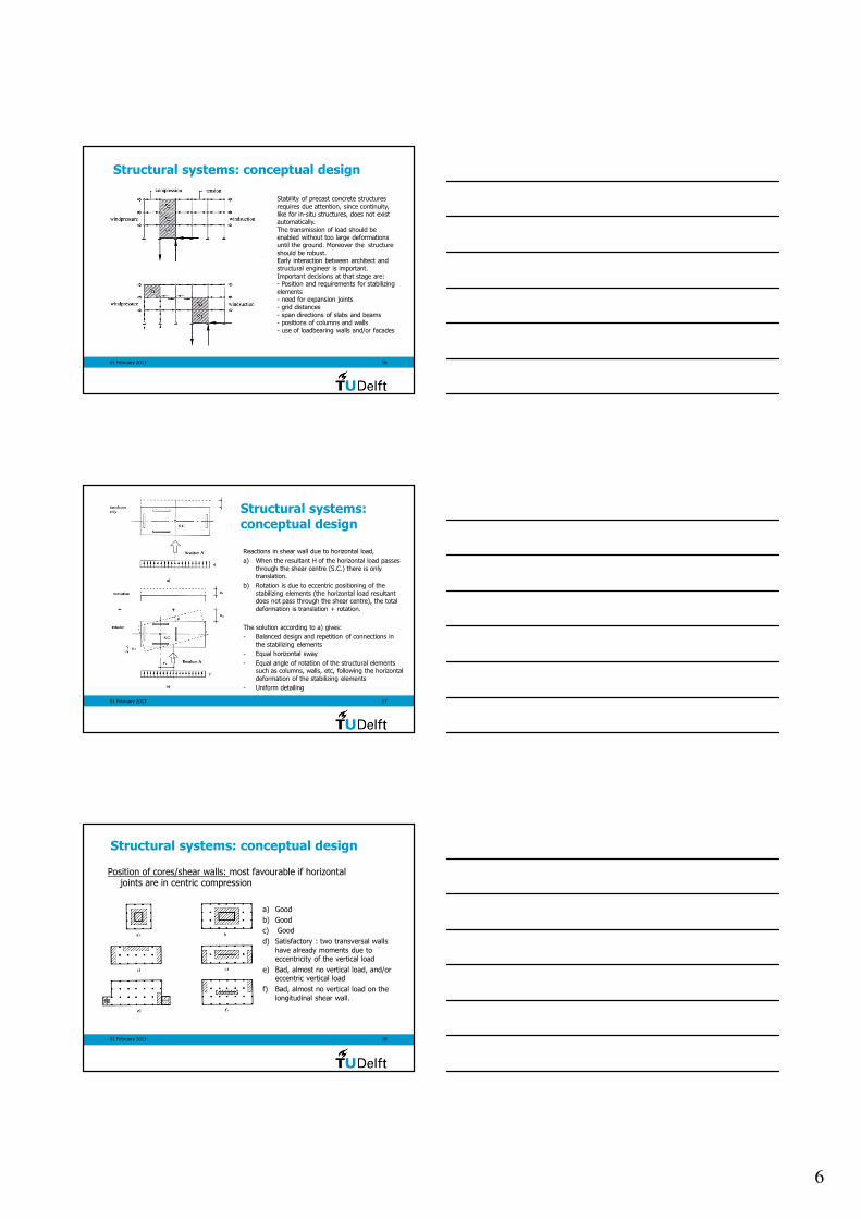
The Wing floor withintegrated installations
Basic precast concrete systems
Floor and roof systems
01 February 2013 11
Basic precast concrete systems:
Wall systems: Load-bearing walls
Load-bearing facade Load bearing cross-walls
Connections required for:
- Wall to wall at interior and exterior vertical joints- Wall to wall at interior and exterior horizontal joints
- Wall to base/foundations
12
Example of a non-bearing facade wall
Basic precast concrete systems:
Wall systems:
The connections of non-bearing walls are mainly facade to beam. Non-bearing walls are
normally designed to carry their own dead load. However, as an alternative, non-bearing facade walls can be connected to to the adjacent load bearing system in such a way that the
dead load of each wall element is supported by the main system.
5
13
Example of a non-bearing facade wall
Basic precast concrete systems:
Wall systems:
Prefabricated walls can be used as a
part of the stabilizing system to resist horizontal loads in their own
plane.In that case the precast wall should
behave like one structural unit composed of interacting wall
elements (lower figure). This structural interaction within the wall
needs to be secured by structural
connections that resist the required shear forces, tensile forces and
compressive forces.
01 February 2013 14
Basic precast concrete systems
Moment resisting frame systems
H-shaped elements and portal frame elements can be used for stabilization. The elements are
connected in areas where flexural resistance is not required, at points of contraflexure. However, the frames are very sensitive to dimensional deviations. The transport limits the dimensions. Actually
those systems are not often applied in non-seismic regions.
15
Basic precast concrete systems:
Cell systems:
Closed cell elements Open cell elements with U-section Elevator shaft cell
Precast concrete cell systems are composed of closed cell elements or open cell elements with U-or L-section. Complete structures can be made by combining cell-elements. However, it is more
common to use cell elements for specific parts of the structure, for instance wet areas, and combine these with ordinary walls and floor systems.
The cell element system is not extensively used, because of transport problems and lack of flexibility in the layout of projects
6
01 February 2013 16
Structural systems: conceptual design
Stability of precast concrete structures
requires due attention, since continuity, like for in-situ structures, does not exist
automatically.The transmission of load should be
enabled without too large deformations until the ground. Moreover the structure
should be robust. Early interaction between architect and
structural engineer is important.
Important decisions at that stage are:- Position and requirements for stabilizing
elements- need for expansion joints
- grid distances- span directions of slabs and beams
- positions of columns and walls
- use of loadbearing walls and/or facades
01 February 2013 17
Structural systems: conceptual design
Reactions in shear wall due to horizontal load,
a) When the resultant H of the horizontal load passes
through the shear centre (S.C.) there is only
translation.
b) Rotation is due to eccentric positioning of the
stabilizing elements (the horizontal load resultant does not pass through the shear centre), the total
deformation is translation + rotation.
The solution according to a) gives:
- Balanced design and repetition of connections in
the stabilizing elements
- Equal horizontal sway
- Equal angle of rotation of the structural elements such as columns, walls, etc, following the horizontal
deformation of the stabilizing elements
- Uniform detailing
01 February 2013 18
Structural systems: conceptual design
Position of cores/shear walls: most favourable if horizontal joints are in centric compression
a) Good
b) Good
c) Good
d) Satisfactory : two transversal walls
have already moments due to eccentricity of the vertical load
e) Bad, almost no vertical load, and/oreccentric vertical load
f) Bad, almost no vertical load on the
longitudinal shear wall.
7
01 February 2013 19
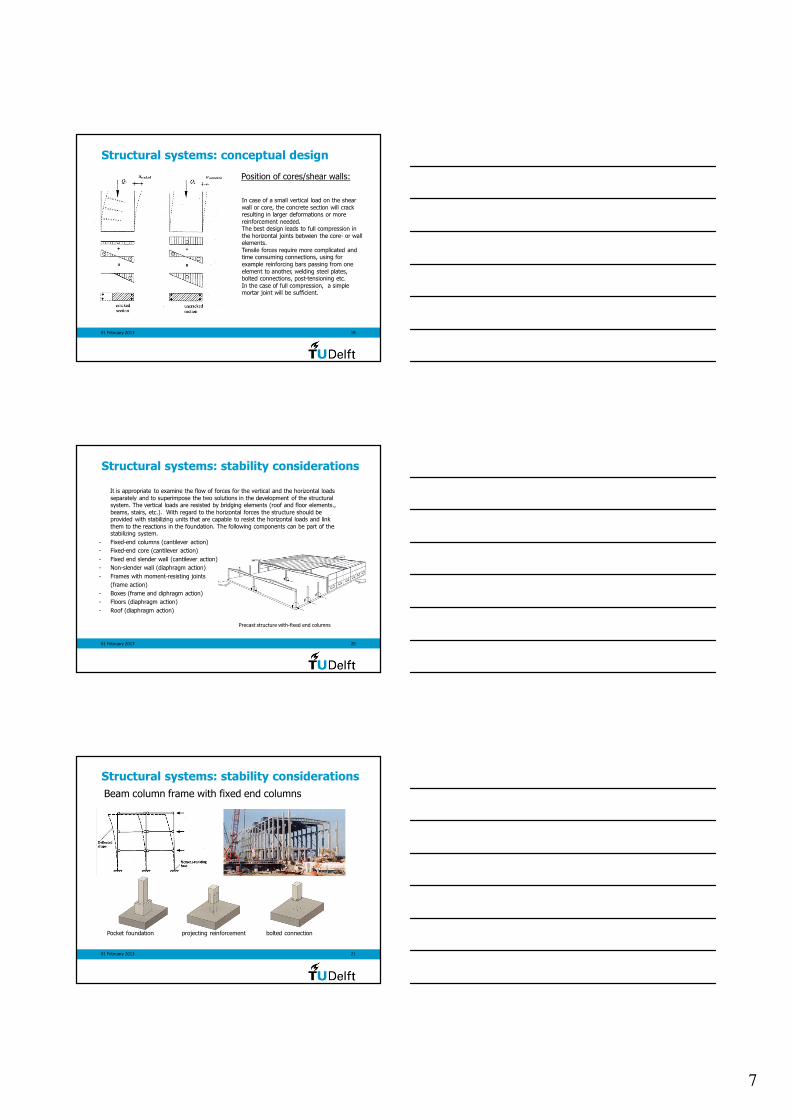
Structural systems: conceptual design
Position of cores/shear walls:
In case of a small vertical load on the shear
wall or core, the concrete section will crack resulting in larger deformations or more
reinforcement needed.The best design leads to full compression in
the horizontal joints between the core- or wall elements.
Tensile forces require more complicated and time consuming connections, using for
example reinforcing bars passing from one
element to another, welding steel plates, bolted connections, post-tensioning etc.
In the case of full compression, a simple mortar joint will be sufficient.
01 February 2013 20
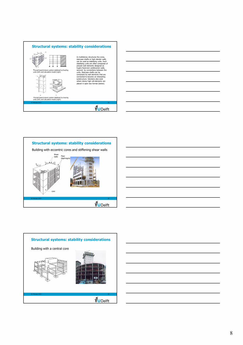
Structural systems: stability considerations
Precast structure with-fixed end columns
It is appropriate to examine the flow of forces for the vertical and the horizontal loads
separately and to superimpose the two solutions in the development of the structuralsystem. The vertical loads are resisted by bridging elements (roof and floor elements.,
beams, stairs, etc.). With regard to the horizontal forces the structure should beprovided with stabilizing units that are capable to resist the horizontal loads and link
them to the reactions in the foundation. The following components can be part of the stabilizing system.
- Fixed-end columns (cantilever action)
- Fixed-end core (cantilever action)
- Fixed end slender wall (cantilever action)
- Non-slender wall (diaphragm action)
- Frames with moment-resisting joints
(frame action)
- Boxes (frame and diphragm action)
- Floors (diaphragm action)
- Roof (diaphragm action)
01 February 2013 21
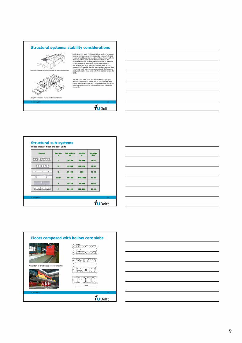
Beam column frame with fixed end columns
Structural systems: stability considerations
Pocket foundation projecting reinforcement bolted connection
8
01 February 2013 22
Structural systems: stability considerations
Precast beam/column system stabilized by bracing units (left) and calculation model (right)
Precast beam/column system stabilized by bracing units (left) and calculation model (right)
In multistorey structures the cores,
staircase shafts or high slender walls can be used as stabilizing units. Such
stabilizing units are often composed of precast wall elements designed as
hughe fixed-end cantilevered walls, secured by connections between the
units. Staircase shafts can be composed by wall elements that are
connected to become an interacting
substructure. Solutions also exist where storey high cell-elements are
placed in open box format (below).
01 February 2013 23
Building with eccentric cores and stiffening shear walls
Structural systems: stability considerations
core
Shear
walls Floor
diaphragms
01 February 2013 24
Building with a central core
Structural systems: stability considerations
9
01 February 2013 25
Structural systems: stability considerations
For less slender walls the flexural failure mode of behaviour is not as pronounced as in more slender walls, which resist horizontal load by cantilever action. In less slender walls the shear capacity in joints and in the connections to the foundation can with relatively small measures be sufficient
for stabilization by diaphragm action. For this reason precast walls are often used as stabilizing units. In this respect it is favourable that the walls are load-bearing, since the vertical load, which gives compression in the horizontal joints, reduces the need for tensile force transfer across the
joints.
The horizontal loads must be transferred by diaphragm action in precast floors (and roofs) to the stabilizing units.
Connections between the floors or roofs and the stabilizing units interact to resist the horizontal load as shown in the figure left.
Stabilization with diaphragm action in non-slender walls
Diaphragm action in precast floors and roofs
01 February 2013 26
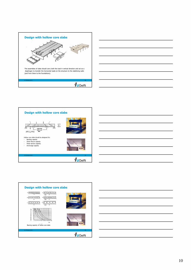
Structural sub-systems
Precast floors
Types precast floor and roof units
Floor type Max. span
m
Floor thickness
mm
Unit width
m
Unit weight
kN/m²
7 120 - 200 300 - 600 2,1 – 3,2
20 120 - 500 600 – 1200 2.2 – 5.2
12 175 – 355 2400 1.2 – 1.8
24 (30) 200 – 800 2400 – 3000 2.0 – 5.0
6 100 - 250 300 - 600 0,7 – 3,0
7 100 – 200 600 – 2400 2.4 – 4.8
01 February 2013 27
Floors composed with hollow core slabs
Production of prestressed hollow core slabs
10
01 February 2013 28
Design with hollow core slabs
The assemblee of slabs should carry both the load in vertical direction and act as a
diaphragm to transfer the horizontal loads on the structure to the stabilizing walls
(and from there to the foundations).
01 February 2013 29
Hollow core slabs should be designed for:
- Bending capacity
- Shear flexure capacity
- Shear tension capacity
- Anchorage capacity
Design with hollow core slabs
01 February 2013 30
Bearing capacity of hollow core slabs
Design with hollow core slabs
11
01 February 2013 31
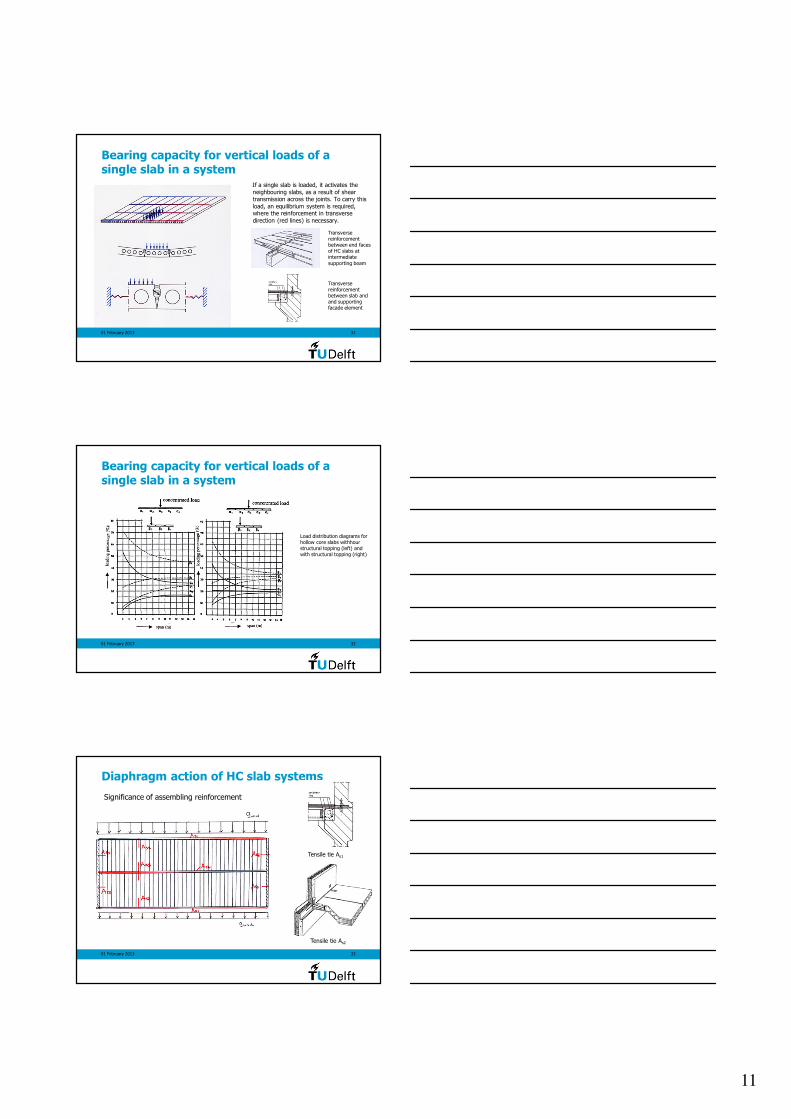
Bearing capacity for vertical loads of a single slab in a system
If a single slab is loaded, it activates the
neighbouring slabs, as a result of shear transmission across the joints. To carry this
load, an equilibrium system is required, where the reinforcement in transverse
direction (red lines) is necessary.
Transverse reinforcement between end faces of HC slabs at intermediate
supporting beam
Transverse reinforcement between slab and and supporting facade element
01 February 2013 32
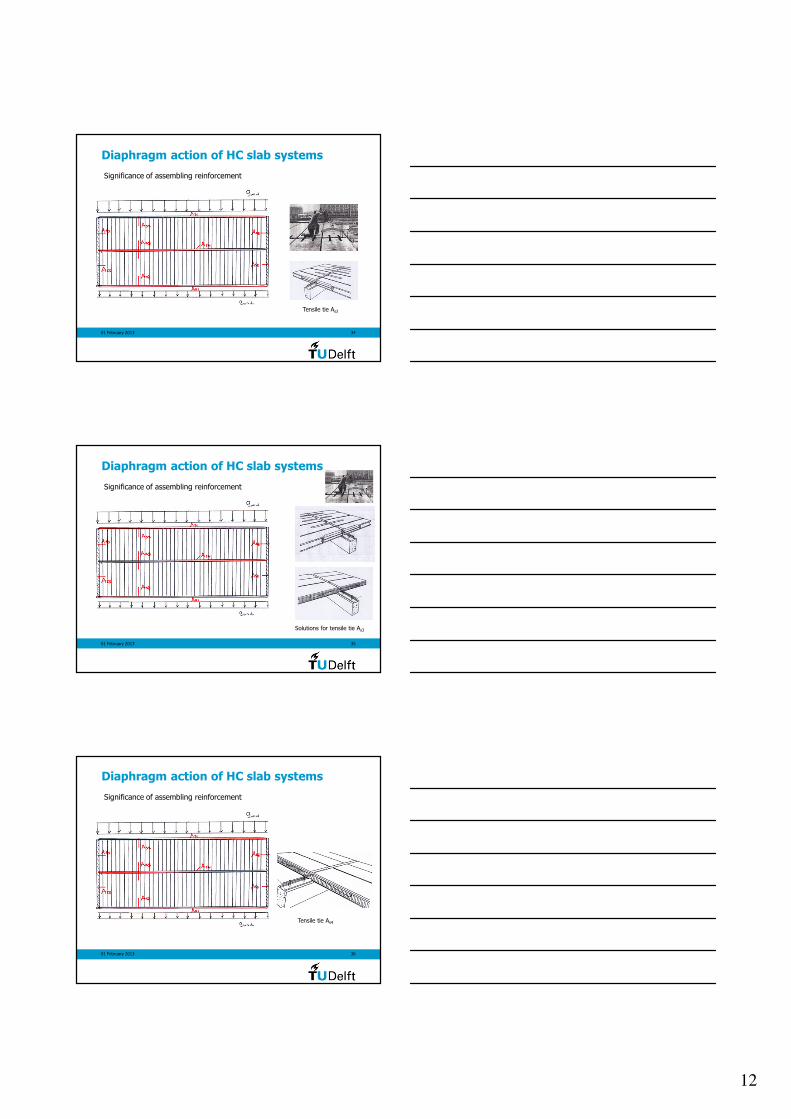
Bearing capacity for vertical loads of a single slab in a system
Load distribution diagrams for hollow core slabs withhour structural topping (left) and with structural topping (right)
01 February 2013 33
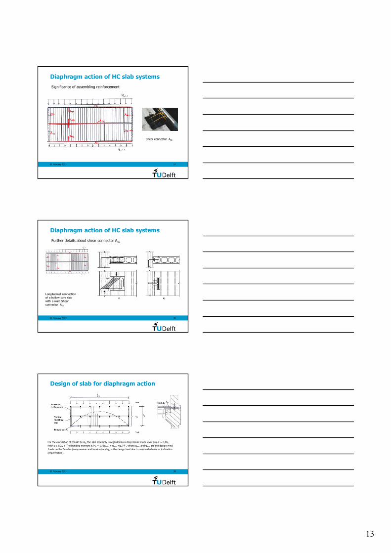
Diaphragm action of HC slab systems
Significance of assembling reinforcement
Tensile tie As1
Tensile tie As2
12
01 February 2013 34
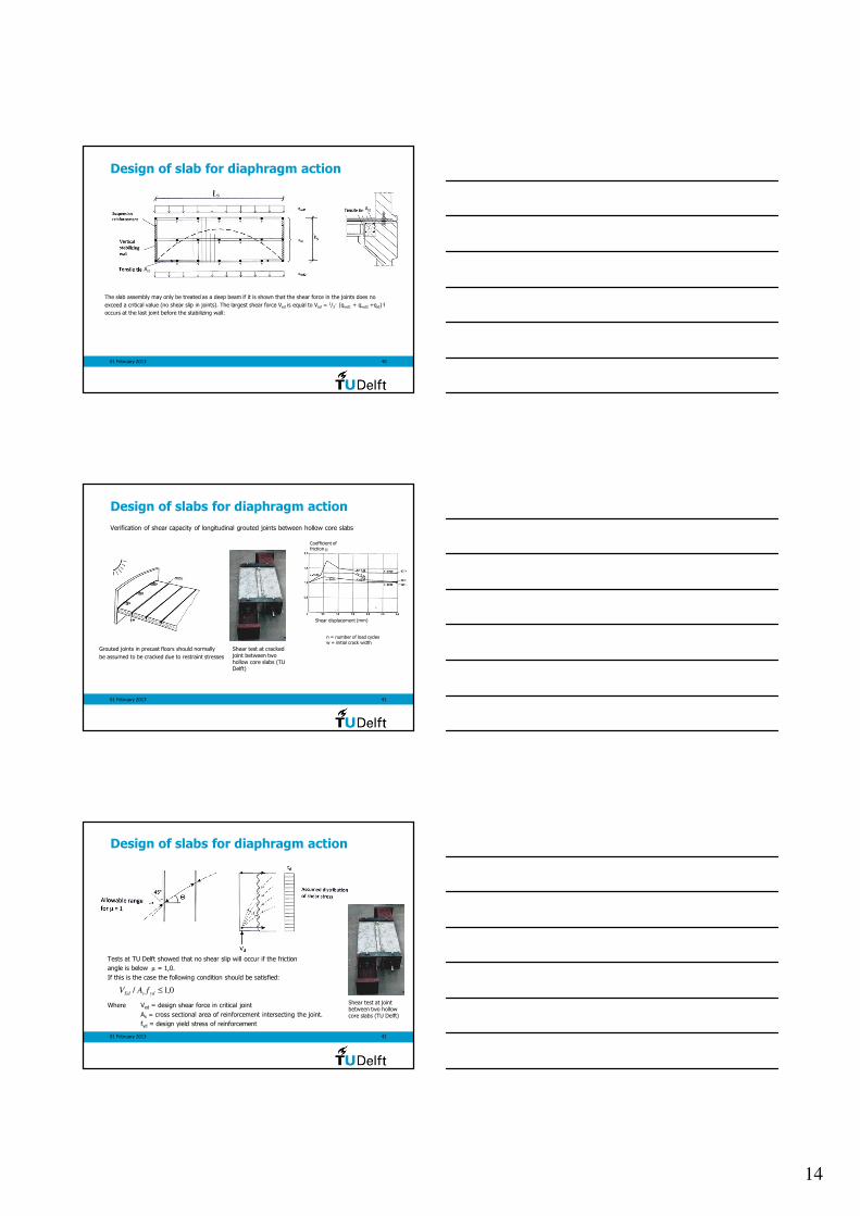
Diaphragm action of HC slab systems
Significance of assembling reinforcement
Tensile tie As3
01 February 2013 35
Diaphragm action of HC slab systems
Significance of assembling reinforcement
Solutions for tensile tie As3
01 February 2013 36
Diaphragm action of HC slab systems
Significance of assembling reinforcement
Tensile tie As4
13
01 February 2013 37
Diaphragm action of HC slab systems
Significance of assembling reinforcement
Shear connector As5
01 February 2013 38
Diaphragm action of HC slab systems
Further details about shear connector As5
Longitudinal connection
of a hollow core slab with a wall: Shear
connector As5
01 February 2013 39
Design of slab for diaphragm action
For the calculation of tensile tie As1 the slab assembly is regarded as a deep beam: inner lever arm z = 0,8hs
(with z ≤ 0,2ls ). The bending moment is Md = 1/8·(qwd1 + qwd2 +qid)·l2 , where qwd1 and qwd2 are the design wind
loads on the facades (compression and tension) and qid is the design load due to unintended column inclination
(imperfection).
As1
As1
14
01 February 2013 40
Design of slab for diaphragm action
The slab assembly may only be treated as a deep beam if it is shown that the shear force in the joints does no
exceed a critical value (no shear slip in joints). The largest shear force Ved is equal to Ved = 1/2· (qwd1 + qwd2 +qid)·l
occurs at the last joint before the stabilizing wall:
As1
As1
01 February 2013 41
Design of slabs for diaphragm action
Grouted joints in precast floors should normally
be assumed to be cracked due to restraint stresses
Shear test at cracked joint between two hollow core slabs (TU Delft)
Verification of shear capacity of longitudinal grouted joints between hollow core slabs
Shear displacement (mm)
Coefficient offriction µ
n = number of load cyclesw = initial crack width
01 February 2013 42
Design of slabs for diaphragm action
Tests at TU Delft showed that no shear slip will occur if the friction
angle is below µ = 1,0.
If this is the case the following condition should be satisfied:
Where Ved = design shear force in critical joint
As = cross sectional area of reinforcement intersecting the joint.
fyd = design yield stress of reinforcement
0,1/ ≤ydsEd fAV
Shear test at joint between two hollow core slabs (TU Delft)
15
01 February 2013 43
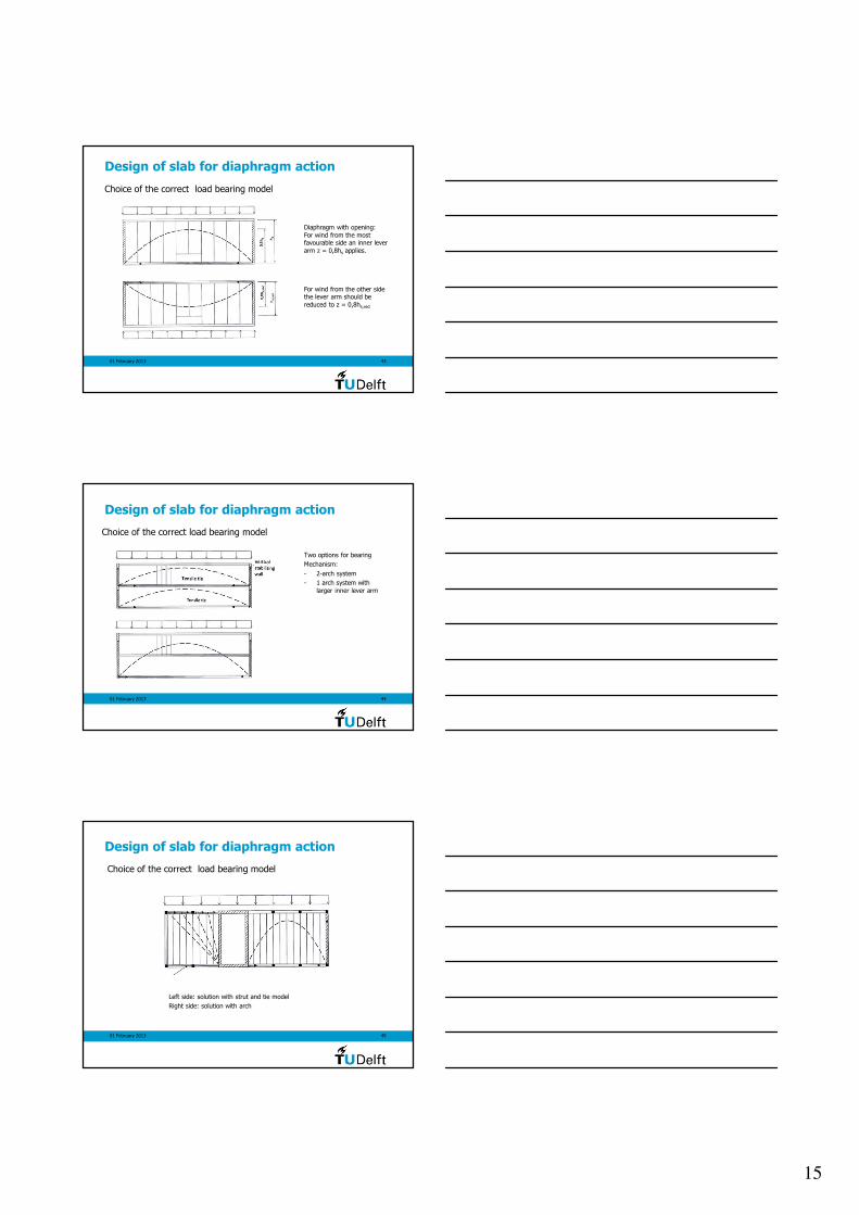
Design of slab for diaphragm action
Choice of the correct load bearing model
Diaphragm with opening:
For wind from the most favourable side an inner lever
arm z = 0,8hs applies.
For wind from the other side the lever arm should be
reduced to z = 0,8hs,red
01 February 2013 44
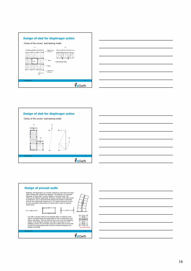
Design of slab for diaphragm action
Choice of the correct load bearing model
Two options for bearing
Mechanism:
- 2-arch system
- 1 arch system with
larger inner lever arm
01 February 2013 45
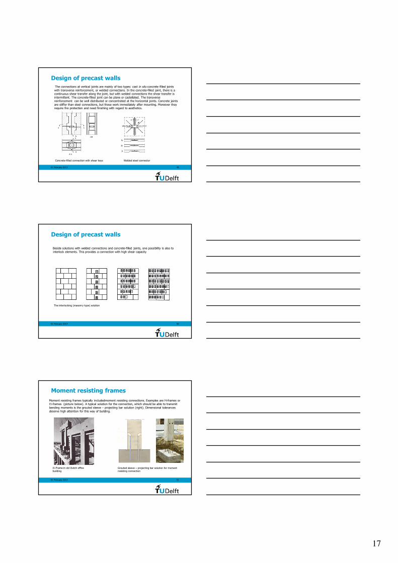
Design of slab for diaphragm action
Choice of the correct load bearing model
Left side: solution with strut and tie model
Right side: solution with arch
16
01 February 2013 46
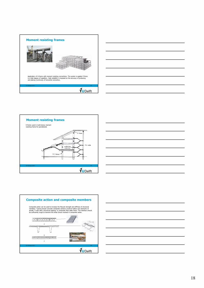
Design of slab for diaphragm action
Choice of the correct load bearing model
01 February 2013 47
Design of slab for diaphragm action
Choice of the correct load bearing model
01 February 2013 48
Design of precast walls
Stabilizing wall diaphragms are normally subjected to axial load and sustain
higher stresses than precast floor diagrams. The stiffness is an important parameter of shear walls. If cracks develop in horizontal joints, this
influences the stiffness significantly. Whenever possible, shear walls should be designed in such a way that tensile stresses are avoided in horizontal
joints or only small tensile stresses occur. It is mostly economical to have as much as possible vertical load on te shear walls in order to suppress
tensile forces.
The walls in precast shafts can be designed either as individual shear
walls or connected along the vertical joints to form a closed open cross section (see figure). Then the shaft will act as one unit in the stabilizing
system. If this interaction between the walls is accounted for in the stabilizing system, the connections along the vertical joints must be able
to resist the corresponding shear forces and should be designed and detailed accordingly Tie reinforcement
17
01 February 2013 49
Design of precast walls
The connections at vertical joints are mainly of two types: cast in situ concrete filled joints
with transverse reinforcement, or welded connections. In the concrete-filled joint, there is a continuous shear transfer along the joint, but with welded connections the shear transfer is
intermittent. The concrete-filled joint can be plane or castellated. The transverse reinforcement can be well distributed or concentrated at the horizontal joints. Concrete joints
are stiffer than steel connections, but those work immediately after mounting. Moreover they require fire protection and need finishing with regard to aesthetics.
Concrete-filled connection with shear keys Welded steel connector
01 February 2013 50
Design of precast walls
Beside solutions with welded connections and concrete-filled joints, one possibility is also to
interlock elements. This provides a connection with high shear capacity
The interlocking (masonry type) solution
01 February 2013 51
Moment resisting frames
Moment resisting frames typically includedmoment resisting connections. Examples are H-frames or Π-frames (picture below). A typical solution for the connection, which should be able to transmit
bending moments is the grouted sleeve – projecting bar solution (right). Dimensional tolerances
deserve high attention for this way of building.
Π-Frame in old Dutch office
building Grouted sleeve – projecting bar solution for moment resisting connection
18
01 February 2013 52
Moment resisting frames
Application of H-frame with moment resisting connections. The system is applied if there
is a high degree of repetition. High reliabiltiy is imposed on the accuracy of producing and placing (continuity of horizontal connection,
01 February 2013 53
H-frame used in multi-storey moment
resisting frame for grandstands
Moment resisting frames
01 February 2013 54
Composite action and composite members
Composite action can be used to increase the flexural strength and stiffness of structural
members. Typical precast concrete composite sections could be hollow core elements of double T-units with a structural topping, or composite floor-plate floors. The interface should
be sufficiently rough to transmit the shear forces involved in composite action.
19
01 February 2013 55
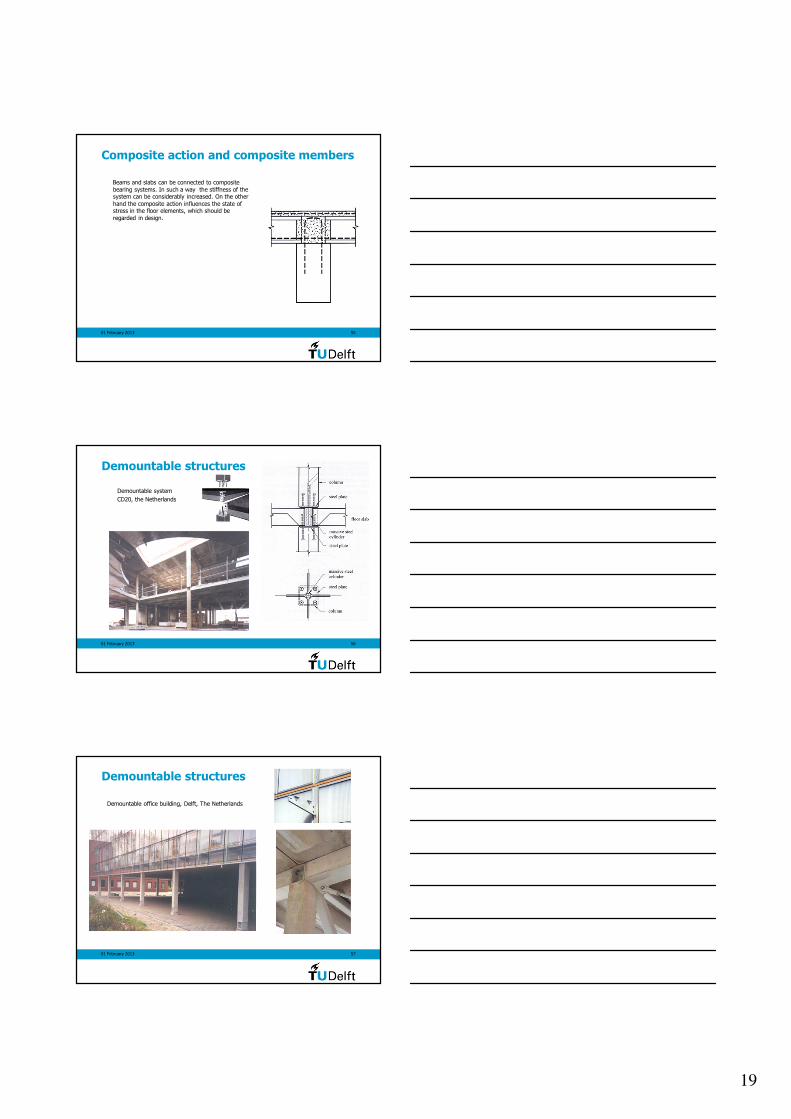
Composite action and composite members
Beams and slabs can be connected to composite
bearing systems. In such a way the stiffness of the system can be considerably increased. On the other
hand the composite action influences the state of stress in the floor elements, which should be
regarded in design.
01 February 2013 56
Demountable structures
Demountable system
CD20, the Netherlands
01 February 2013 57
Demountable structures
Demountable office building, Delft, The Netherlands