Embed Size (px)
Citation preview
2 Storey Clay Brick Veneer Construction — Made Easy
Marketed by the NZ Clay Brick & Paver Manufacturer’s Association
DESIGN NOTE TB1 - MAY 2012

www.thinkbrick.co.nz
Contents
Introduction 5
1.0 Design Limitations 6
Concrete Masonry Buildings
2.0 Building Regulations 6
3.0 Veneer Weight Limitations 6
4.0 Design Height Limitations 7
5.0 Framing 8
Studs
Gable Ends
Mid-floor framing
Structural Beams
6.0 Bracing 8
Table 1.0 Bracing Units
Table 2.0 Bracing demand reduction R(BU)
Table 3.0 K Values
7.0 Fire Resistance 10
8.0 System Components and Accessories 10
Building Paper
Flexible Flashing Tapes
Air Seals
9.0 Brick Cavity and Wall Ties 10
Cavity
Brick ties
Table 4.0 Length of tie
Tie Spacings
10.0 Shelf Angles – Brick Veneer Above Roof lines 11
Metal Shelf Angles
– Durability
– Size of Angles
– Installation and Fixings
– Temporary Support Block
Temporary Support Block
Timber Shelf Angles
– Installation and Fixings
Shelf Angles Under Windows
11.0 Brick Veneer Panels – Limited Support 14
12.0 Shelf Angles & Secret Gutters – Flashings 14
Bottom of Sloping Shelf Angles
13.0 Plastering 15
14.0 Mortar 16
15.0 Bricklaying 16
Joint Reinforcement
Control Joints
16.0 Design Aspects 17
Decks, Veranda’s and attachments
Lintels – Window and Door Openings
Method 1 – Traditional Steel Angle
Table 5.0 Lintel Bar Sizes
Method 2 – Fixing Lintel Angles to the supporting frame
Table 6.0 – Size of Lintel Angles – Screw-fixed
Method 3 – Steel-less Lintels
Table 7.0 – Timber Lintels - sizing
Table 8.0 – Timber Lintels - sizing
Table 9.0 – Timber Lintels - sizing
Method 4 – Precast Reinforced Clay Lintels
17.0 Technical Support 19
Technical Details 20
Figures 1 – 18
Figures 23
A – E, Lintel Options
F – Head Flashing
G – Temporary Support Brackets
APPENDIX – Specification 25
THE 2012 2-STOREY CLAY BRICK GUIDE / 5
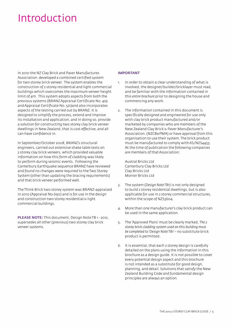
Introduction
In 2010 the NZ Clay Brick and Paver Manufactures
Association developed a combined certified system
for two storey brick veneer. The system enables the
construction of 2 storey residential and light commercial
buildings which overcomes the maximum veneer height
limit of 4m. This system adopts aspects from both the
previous systems (BRANZ Appraisal Certificate No. 429
and Appraisal Certificate No. 521)and also incorporates
aspects of the testing carried out by BRANZ. It is
designed to simplify the process, extend and improve
its installation and application, and in doing so, provide
a solution for constructing two storey clay brick veneer
dwellings in New Zealand, that is cost effective, and all
can have confidence in.
In September/October 2008, BRANZ’s structural
engineers, carried out extensive shake table tests on
2 storey clay brick veneers, which provided valuable
information on how this form of cladding was likely
to perform during seismic events. Following the
Canterbury Earthquake sequence BRANZ have reviewed
and found no changes were required to the Two Storey
System (other than updating the bracing requirements)
and that brick veneer performed well.
The Think Brick two storey system was BRANZ-appraised
in 2010 (Appraisal No.690) and is for use in the design
and construction two storey residential & light
commercial buildings.
PLEASE NOTE: This document, Design Note TB 1 - 2012,
supersedes all other (previous) two storey clay brick
veneer systems.
IMPORTANT
1. In order to obtain a clear understanding of what is
involved, the designer/builder/bricklayer must read,
and be familiar with the information contained in
this entire brochure prior to designing the house and
commencing any work.
2. The information contained in this document is
specifically designed and engineered for use only
with clay brick product manufactured and/or
marketed by companies who are members of the
New Zealand Clay Brick & Paver Manufacturer’s
Association. (NZCB&PMA) or have approval from this
organisation to use their system. The brick product
must be manufactured to comply with AS/NZS4455.
At the time of publication the following companies
are members of that Association:
Austral Bricks Ltd
Canterbury Clay Bricks Ltd
Clay Bricks Ltd
Monier Bricks Ltd
3. The system (Design Note TB1) is not only designed
to build 2 storey residential dwellings, but is also
applicable for use in 2 storey commercial structures,
within the scope of NZS3604.
4. More than one manufacturer’s clay brick product can
be used in the same application.
5. The ‘Approved Plans’ must be clearly marked, The 2
storey brick cladding system used on this building must
be completed to ‘Design Note TB1’ – no substitute brick
product is permitted.
6. It is essential, that each 2 storey design is carefully
detailed on the plans using the information in this
brochure as a design guide. It is not possible to cover
every potential design aspect and this brochure
is not intended as a substitute for good design,
planning, and detail. Solutions that satisfy the New
Zealand Building Code and fundamental design
principles are always an option.
THE 2012 2-STOREY CLAY BRICK GUIDE / 6
1.0 DESIGN LIMITATIONS
The following ‘Design Limitations’ apply to this system.
When the structure does not meet these requirements
then ‘specific engineering design’, (S.E.D) is required.
• Concrete ground floor construction.
• Up to 2.0 kPa and 3.0 kPa floor loadings.
• Timber frame construction in accordance with
NZS3604 and/or concrete masonry construction in
accordance with NZS 4229.
• Maximum thickness of the brick veneer is 90 mm.
• The maximum brick height to length ratio is 0.7. On
all veneers that exceed a ratio of 0.5, the bricks are to
be half-bonded. Selected architectural detailing such
as ‘soldier courses’, ‘quoins’, rows of ‘header bricks’
and the like, are excluded from this requirement.
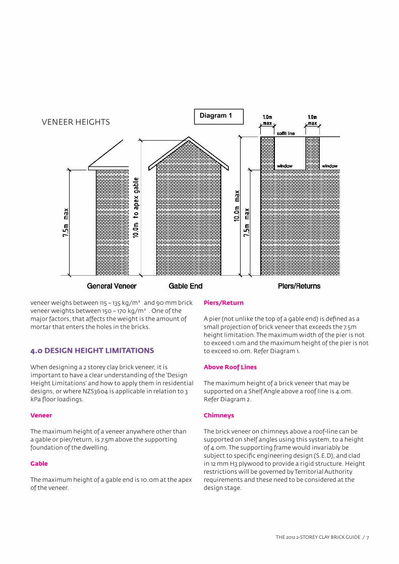
• General veneer height of 7.5m max. Excluding
gables and piers. ( refer Diagram 1- Design Height
Limitations)
• The scope limitations of NZBC Acceptable Solution
E2/AS1 Paragraph 1.1 in terms of floor area, and with a
maximum of 2 stories.
• Situated in NZS 3604 Building Wind Zones up to and
including ‘Very High’. Wind bracing demand must be
calculated in accordance with NZS3604 as it may be
the critical lateral loading case.
• A risk score of 0 – 20, calculated in accordance with
NZBC Acceptable Solution E2/AS1 Table 2
• Unless otherwise stated in this document, Design
Note TB1 – 2 Storey Clay Brick Veneer Construction, all
aspects in regards to the installation of the brick
veneer will conform to the requirements of NZS 3604,
NZS 4229 and NZS 4210.
Concrete Masonry Buildings
The general specification and requirements covered
by this document, Design Note TB1, may be applied to
structures that are designed to NZS 4229, where the
supporting structure is concrete block or concrete walled
structures.
The fixing of brick ties must satisfy the requirements of
AS/NZS 2699.1:2000 for medium duty (EM) ties.
2.0 BUILDING REGULATIONS
Design Note TB1 – 2 Storey Brick Veneer Construction,
if designed, used and installed in accordance with
the statements and conditions of this literature, and
supporting BRANZ Appraisal, will meet the following
provisions of the New Zealand Building Code:
• Clause B1 Structure
• Clause B2 Durability
• Clause C3 Spread of Fire
• Clause E2 External Moisture
• Clause F2 Hazardous Building Materials
3.0 VENEER WEIGHT LIMITATIONS
The installed weight of the clay brick veneer using this
system, must comply with the following parameters.
• Veneer weight not to exceed 180 kg/m² (will
accommodate 90 mm thick veneers)
• In situations where the veneer is to be plastered,
up to 20 mm in thickness may be applied to a total
weight of 180 kg/m² maximum.
NOTE: The veneer weights based on a 10 mm mortar
joint, can be obtained from the manufacturers covered by
this document should that be necessary. A 70 mm brick
The 2012 2-Storey Clay Brick Guide
THE 2012 2-STOREY CLAY BRICK GUIDE / 7
veneer weighs between 115 – 135 kg/m² and 90 mm brick
veneer weights between 150 – 170 kg/m². One of the
major factors, that affects the weight is the amount of
mortar that enters the holes in the bricks.
4.0 DESIGN HEIGHT LIMITATIONS
When designing a 2 storey clay brick veneer, it is
important to have a clear understanding of the ‘Design
Height Limitations’ and how to apply them in residential
designs, or where NZS3604 is applicable in relation to 3
kPa floor loadings.
Veneer
The maximum height of a veneer anywhere other than
a gable or pier/return, is 7.5m above the supporting
foundation of the dwelling.
Gable
The maximum height of a gable end is 10.0m at the apex
of the veneer.
Piers/Return
A pier (not unlike the top of a gable end) is defined as a
small projection of brick veneer that exceeds the 7.5m
height limitation. The maximum width of the pier is not
to exceed 1.0m and the maximum height of the pier is not
to exceed 10.0m. Refer Diagram 1.
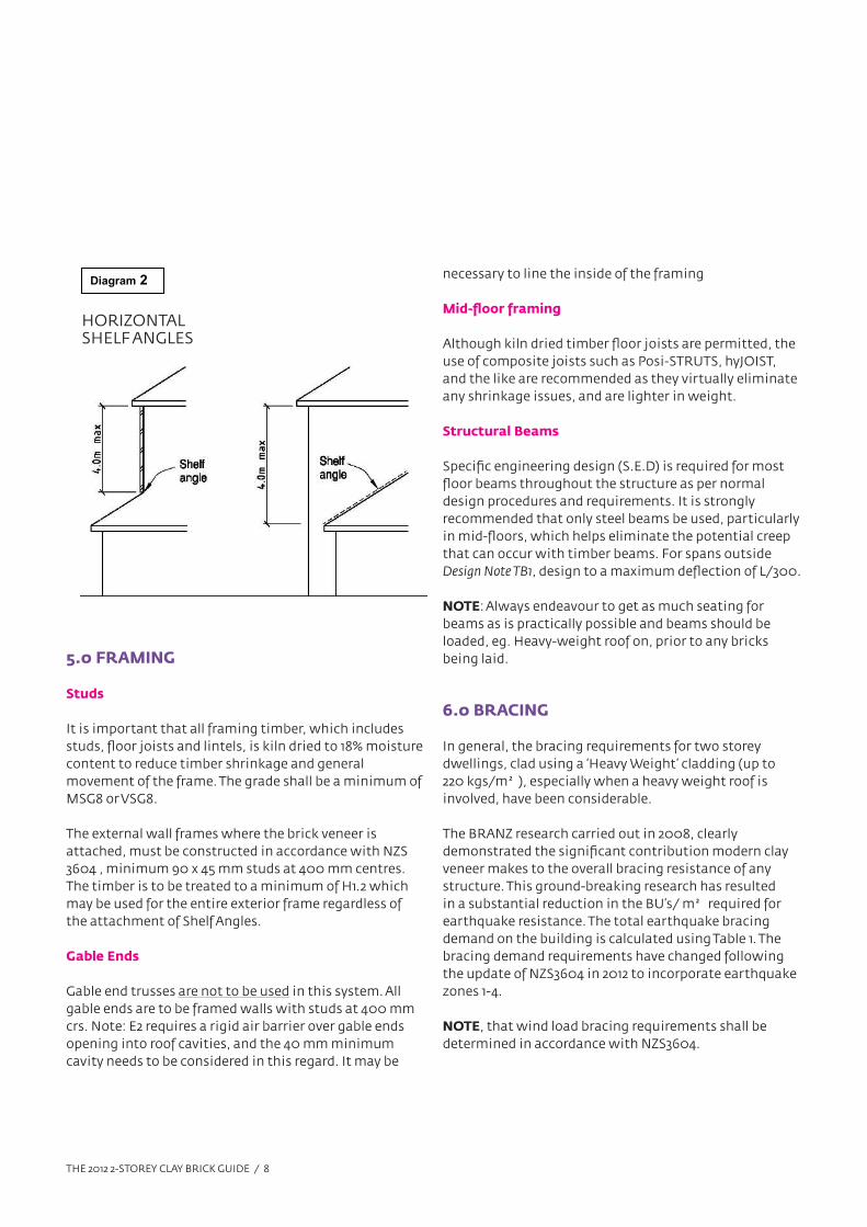
Above Roof Lines
The maximum height of a brick veneer that may be
supported on a Shelf Angle above a roof line is 4.0m.
Refer Diagram 2.
Chimneys
The brick veneer on chimneys above a roof-line can be
supported on shelf angles using this system, to a height
of 4.0m. The supporting frame would invariably be
subject to specific engineering design (S.E.D), and clad
in 12 mm H3 plywood to provide a rigid structure. Height
restrictions will be governed by Territorial Authority
requirements and these need to be considered at the
design stage.
Diagram 1 VENEER HEIGHTS
THE 2012 2-STOREY CLAY BRICK GUIDE / 8
Diagram 2
HORIZONTAL SHELF ANGLES
5.0 FRAMING
Studs
It is important that all framing timber, which includes
studs, floor joists and lintels, is kiln dried to 18% moisture
content to reduce timber shrinkage and general
movement of the frame. The grade shall be a minimum of
MSG8 or VSG8.
The external wall frames where the brick veneer is
attached, must be constructed in accordance with NZS
3604 , minimum 90 x 45 mm studs at 400 mm centres.
The timber is to be treated to a minimum of H1.2 which
may be used for the entire exterior frame regardless of
the attachment of Shelf Angles.
Gable Ends
Gable end trusses are not to be used in this system. All
gable ends are to be framed walls with studs at 400 mm
crs. Note: E2 requires a rigid air barrier over gable ends
opening into roof cavities, and the 40 mm minimum
cavity needs to be considered in this regard. It may be
necessary to line the inside of the framing
Mid-floor framing
Although kiln dried timber floor joists are permitted, the
use of composite joists such as Posi-STRUTS, hyJOIST,
and the like are recommended as they virtually eliminate
any shrinkage issues, and are lighter in weight.
Structural Beams
Specific engineering design (S.E.D) is required for most
floor beams throughout the structure as per normal
design procedures and requirements. It is strongly
recommended that only steel beams be used, particularly
in mid-floors, which helps eliminate the potential creep
that can occur with timber beams. For spans outside
Design Note TB1, design to a maximum deflection of L/300.
NOTE: Always endeavour to get as much seating for
beams as is practically possible and beams should be
loaded, eg. Heavy-weight roof on, prior to any bricks
being laid.
6.0 BRACING
In general, the bracing requirements for two storey
dwellings, clad using a ‘Heavy Weight’ cladding (up to
220 kgs/m²), especially when a heavy weight roof is
involved, have been considerable.
The BRANZ research carried out in 2008, clearly
demonstrated the significant contribution modern clay
veneer makes to the overall bracing resistance of any
structure. This ground-breaking research has resulted
in a substantial reduction in the BU’s/ m² required for
earthquake resistance. The total earthquake bracing
demand on the building is calculated using Table 1. The
bracing demand requirements have changed following
the update of NZS3604 in 2012 to incorporate earthquake
zones 1-4.
NOTE, that wind load bracing requirements shall be
determined in accordance with NZS3604.
THE 2012 2-STOREY CLAY BRICK GUIDE / 9
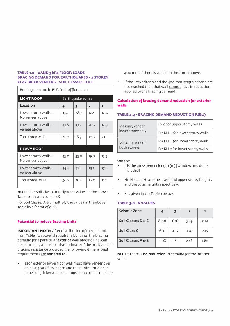
TABLE 1.0 – 2 AND 3 kPa FLOOR LOADS
BRACING DEMAND FOR EARTHQUAKES – 2 STOREY
CLAY BRICK VENEERS – SOIL CLASSES D & E
Bracing demand in BU’s/m² of floor area
LIGHT ROOF Earthquake zones
Location 4 3 2 1
Lower storey walls –
No veneer above
37.4 28.7 17.2 12.0
Lower storey walls –
Veneer above
43.8 33.7 20.2 14.3
Top storey walls 22.0 16.9 10.2 7.1
HEAVY ROOF
Lower storey walls –
No veneer above
43.0 33.0 19.8 13.9
Lower storey walls –
Veneer above
54.4 41.8 25.1 17.6
Top storey walls 34.6 26.6 16.0 11.2
NOTE: For Soil Class C multiply the values in the above
Table 1.0 by a factor of 0.8.
For Soil Classes A & B multiply the values in the above
Table by a factor of 0.66.
Potential to reduce Bracing Units
IMPORTANT NOTE: After distribution of the demand
from Table 1.0 above, through the building, the bracing
demand for a particular exterior wall bracing line, can
be reduced by a conservative estimate of the brick veneer
bracing resistance provided the following dimensional
requirements are adhered to.
• each exterior lower floor wall must have veneer over
at least 40% of its length and the minimum veneer
panel length between openings or at corners must be
400 mm, if there is veneer in the storey above.
• if the 40% criteria and the 400 mm length criteria are
not reached then that wall cannot have in reduction
applied to the bracing demand.
Calculation of bracing demand reduction for exterior
walls
TABLE 2.0 - BRACING DEMAND REDUCTION R(BU)
Masonry veneer
lower storey only
R= 0 for upper storey walls
R = KLHL for lower storey walls
Masonry veneer
both storeys
R = KLHU for upper storey walls
R = KLHT for lower storey walls
Where:
• L is the gross veneer length (m) [window and doors
included]
• HL, HU, and HT are the lower and upper storey heights
and the total height respectively.
• K is given in the Table 3 below.
TABLE 3.0 - K VALUES
Seismic Zone 4 3 2 1
Soil Classes D & E 8.00 6.16 3.69 2.61
Soil Class C 6.31 4.77 3.07 2.15
Soil Classes A & B 5.08 3.85 2.46 1.69
NOTE: There is no reduction in demand for the interior
walls.
THE 2012 2-STOREY CLAY BRICK GUIDE / 10
7.0 FIRE RESISTANCE
The Two Storey Clay Brick Veneer System has been
tested and shown to have a fire resistance rating of
greater than 30/30/30 when the internal face of the
wall is lined with 13 mm Standard Gib Plasterboard.
The Two Storey Clay Brick Veneer System is suitable
for use as an external wall cladding on all buildings in
accordance with NZBC Acceptable Solution C/AS1 Part
7, Paragraph 7.11.2(a)
In addition to the above comments, PBS Ltd can
provide Fire Rating solutions, worth exploring, using
Eterpan.
8.0 SYSTEM COMPONENTS AND ACCESSORIES
Building Paper
The 2 Storey Brick Veneer Systems must be installed
over building paper or wrap complying with NZBC
Acceptable Solution E2/AS1, Table 23, or other BRANZ
Appraised breather-type membranes. It is strongly
recommended that ‘fire retardant’ building paper is
specified, and is certainly essential if a flashing material
such as ‘Nuraply’ is used, which requires a naked flame
for installation.
NOTE: The building wrap is to be stretched tight over
the frame and secured to the framing using tape that
helps prevent staple pullout when the insulation is
installed, which has the potential to not only reduce the
cavity width, but cause bridging between the veneer
and the frame. The wrap is to be installed horizontally,
continuously around corners, lapped a minimum of
75 mm at horizontal joints and 150 mm minimum over
studs at vertical joints.
Non-rigid air barriers must have an air resistance of
equal to or >0.1MN s/m³. Where rigid sheathings are
>5.0 mm are used, the brick tie fixing length must
be increased by a minimum of the thickness of the
sheathing.
Flexible Flashing Tapes
Flexible sill and jamb flashing tapes shall be installed
around all penetration openings in the structural
frame. Flexible flashing tapes shall comply with NZBC
Acceptable Solutions E2/AS1 Paragraph 4.3.11, or be
covered by a valid BRANZ Appraisal for use around
window and door joinery openings.
Air Seals
Air seals shall be installed in the gap between the
joinery reveal and the opening framing. The air seal
shall comply with NZBC Acceptable Solution E2/AS1
Paragraph 9.1.6, or be a self-expanding, moisture cure
polyurethane foam air seal covered by a valid BRANZ
Appraisal for use around window, door and other wall
penetration openings.
9.0 BRICK CAVITY & WALL TIES
Cavity
The brick veneer cavity is to be a minimum of 40 mm and
a maximum of 60 mm in width. It should be noted that
the cavity width is measured from the tie fixing to the
inside face of the brick veneer.
Washouts are to be installed at the base of these veneers
every 10th brick, and at each corner to facilitate the
cleaning of the cavity during construction.
Brick Ties
The brick ties to be used in this system are to be screw-
fixed brick ties, which comply with NZS2699.1. The
minimum strength tie required is an EM (Earthquake
Medium) tie. The durability is to comply with the
requirements of NZS3604.
Use stainless steel ties in ‘Sea Spray’ zones.
THE 2012 2-STOREY CLAY BRICK GUIDE / 11
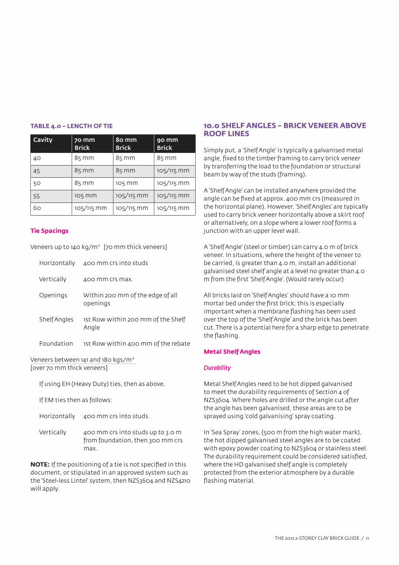
TABLE 4.0 – LENGTH OF TIE
Cavity 70 mm
Brick
80 mm
Brick
90 mm
Brick
40 85 mm 85 mm 85 mm
45 85 mm 85 mm 105/115 mm
50 85 mm 105 mm 105/115 mm
55 105 mm 105/115 mm 105/115 mm
60 105/115 mm 105/115 mm 105/115 mm
Tie Spacings
Veneers up to 140 kg/m² [70 mm thick veneers]
Horizontally 400 mm crs into studs
Vertically 400 mm crs max.
Openings Within 200 mm of the edge of all
openings
Shelf Angles 1st Row within 200 mm of the Shelf
Angle
Foundation 1st Row within 400 mm of the rebate
Veneers between 141 and 180 kgs/m²
[over 70 mm thick veneers]
If using EH (Heavy Duty) ties, then as above.
If EM ties then as follows:
Horizontally 400 mm crs into studs.
Vertically 400 mm crs into studs up to 3.0 m
from foundation, then 300 mm crs
max.
NOTE: If the positioning of a tie is not specified in this
document, or stipulated in an approved system such as
the ‘Steel-less Lintel’ system, then NZS3604 and NZS4210
will apply.
10.0 SHELF ANGLES – BRICK VENEER ABOVE ROOF LINES
Simply put, a ‘Shelf Angle’ is typically a galvanised metal
angle, fixed to the timber framing to carry brick veneer
by transferring the load to the foundation or structural
beam by way of the studs (framing).
A ‘Shelf Angle’ can be installed anywhere provided the
angle can be fixed at approx. 400 mm crs (measured in
the horizontal plane). However, ‘Shelf Angles’ are typically
used to carry brick veneer horizontally above a skirt roof
or alternatively, on a slope where a lower roof forms a
junction with an upper level wall.
A ‘Shelf Angle’ (steel or timber) can carry 4.0 m of brick
veneer. In situations, where the height of the veneer to
be carried, is greater than 4.0 m, install an additional
galvanised steel shelf angle at a level no greater than 4.0
m from the first ‘Shelf Angle’. (Would rarely occur)
All bricks laid on ‘Shelf Angles’ should have a 10 mm
mortar bed under the first brick; this is especially
important when a membrane flashing has been used
over the top of the ‘Shelf Angle’ and the brick has been
cut. There is a potential here for a sharp edge to penetrate
the flashing.
Metal Shelf Angles
Durability
Metal Shelf Angles need to be hot dipped galvanised
to meet the durability requirements of Section 4 of
NZS3604. Where holes are drilled or the angle cut after
the angle has been galvanised, these areas are to be
sprayed using ‘cold galvanising’ spray coating.
In ‘Sea Spray’ zones, (500 m from the high water mark),
the hot dipped galvanised steel angles are to be coated
with epoxy powder coating to NZS3604 or stainless steel.
The durability requirement could be considered satisfied,
where the HD galvanised shelf angle is completely
protected from the exterior atmosphere by a durable
flashing material.
THE 2012 2-STOREY CLAY BRICK GUIDE / 12
Size of Angles
The angle needs to be of sufficient size, that it can
accommodate the cavity width plus support the brick,
but keeping the outside edge of the angle inside the face
of the brick veneer for aesthetics.
The standard size of angles are; 100 x 75 x 6 mm, 100 x 100
x 6 mm, for 70/80 mm brick veneer and 75 x 125 x 6 mm for
90 mm brick veneer. Note: The width of the cavity largely
determines the size of the angle to be used.
Installation and Fixings
It is not critical that ‘Shelf Angles’ are joined or continuous,
brick is more than capable of spanning gaps of say 200
mm should the need arise, as it does from time to time.
The ‘Shelf Angles’ should not be fixed to the framing until
the veneer below has reached its full height so that the
‘Shelf Angle’ can be correctly aligned with the veneer ie.
height of the angle.
IMPORTANT: Where a flashing material is installed
below the ‘Shelf Angle’ and taken up behind it, E2 requires
a minimum gap of 35 mm (rec. design for 50 mm)
between the underside of the angle and the top surface of
the flashing material. This is to prevent leaves and other
debris from restricting the flow of water and to facilitate
cleaning. If the flashing material is installed over the top
of the ‘Shelf Angle’, the angle can be closer to the roof, and
the 35 mm would not apply.
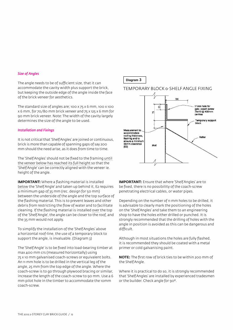
To simplify the installation of the ‘Shelf Angles’ above
a horizontal roof-line, the use of a temporary block to
support the angle, is invaluable. (Diagram 3)
The ‘Shelf Angle’ is to be fixed into load-bearing timber at
max 400 mm crs (measured horizontally) using
75 x 10 mm galvanised coach-screws or equivalent bolts.
An 11 mm hole is to be drilled in the vertical leg of the
angle, 25 mm from the top edge of the angle. Where the
coach-screw is to go through plywood bracing or similar,
increase the length of the coach-screw to 90 mm. Use a 6
mm pilot hole in the timber to accommodate the 10mm
coach-screw.
Diagram 3
TEMPORARY BLOCK & SHELF ANGLE FIXING
IMPORTANT: Ensure that where ‘Shelf Angles’ are to
be fixed, there is no possibility of the coach-screw
penetrating electrical cables, or water pipes.
Depending on the number of 11 mm holes to be drilled, it
is advisable to clearly mark the positioning of the holes
on the ‘Shelf Angles’ and take them to an engineering
shop to have the holes either drilled or punched. It is
strongly recommended that the drilling of holes with the
angle in position is avoided as this can be dangerous and
difficult.
Although in most situations the holes are fully flashed,
it is recommended they should be coated with a metal
primer or cold galvanising paint.
NOTE: The first row of brick ties to be within 200 mm of
the Shelf Angle.
Where it is practical to do so, it is strongly recommended
that ‘Shelf Angles’ are installed by experienced tradesmen
or the builder. Check angle for 90º.
THE 2012 2-STOREY CLAY BRICK GUIDE / 13
Timber Shelf Angles
Experimentation has demonstrated that screw-fixed
brick ties are very good at carrying dead-load, and that
in reality, once the mortar has cured, there is very little
direct load on the Shelf Angle; virtually all the load is
transferred via the ties into the supporting structure.
This development has led to the introduction of timber
shelf angles, which may not be suitable for all situations,
depending on the design.
It is also important to remember that the design of
the timber ‘Shelf Angle’ does not need to be exactly as
detailed below, however, the fundamentals of the design
need to be incorporated in the proposed solution, eg. the
method of fixing must include 100 x 10 galvanised coach-
screws plus 100 x 4 mm FH galv. nails. Fig. 1,3,7
NOTE:
1. That in all cases involving timber ‘Shelf Angles’, the
flashing material is installed over the top of the ‘Shelf
Angle’ providing total protection of the timber.
2. That the width of the ‘Shelf Angle’ may limit the
width of the brick to be used.
3. If the veneer is to be plastered, consideration should
be given to how the bottom edge of the veneer and
its relation to the ’Shelf Angle’ is finished to provide a
crisp edge.
4. The timber to be used in this application must be kiln
dried H3.2
5. Under no circumstances are fixings to penetrate
the flashing membrane on shelf angles through the
horizontal plane.
Installation and Fixings
The following is one method of installing a timber
‘Shelf Angle’ that provides a seating of 90 mm in width,
meaning a 70 mm brick would overhang 20 mm.
Secure a 90 x 45 mm, H3.2 wall plate along the wall, every
400 mm to the studs or load-bearing framing, using
2/100 mm x 4 mm galvanised FH nails. Then install a 100
mm x 10 mm galvanised coach-screw through the wall
plate into each stud, 400 mm centres. The head of the
coach-screw must be countersunk into the plate.
Then fix an additional 90 x 45 mm H3.2 wall plate to the
already installed plate using a minimum of
2/100 x 4 mm galvanised FH nails at 400 mm centres. An
additional 19 mm batten may be added to the
90 mm timber to provide a seating of 109 mm if required.
The batten is to be H3.2 fixed using 60x2.8 Galv. FH nails
at 400 mm crs.
NOTE: The first row of brick ties to be within 200 mm of
the Shelf Angle.
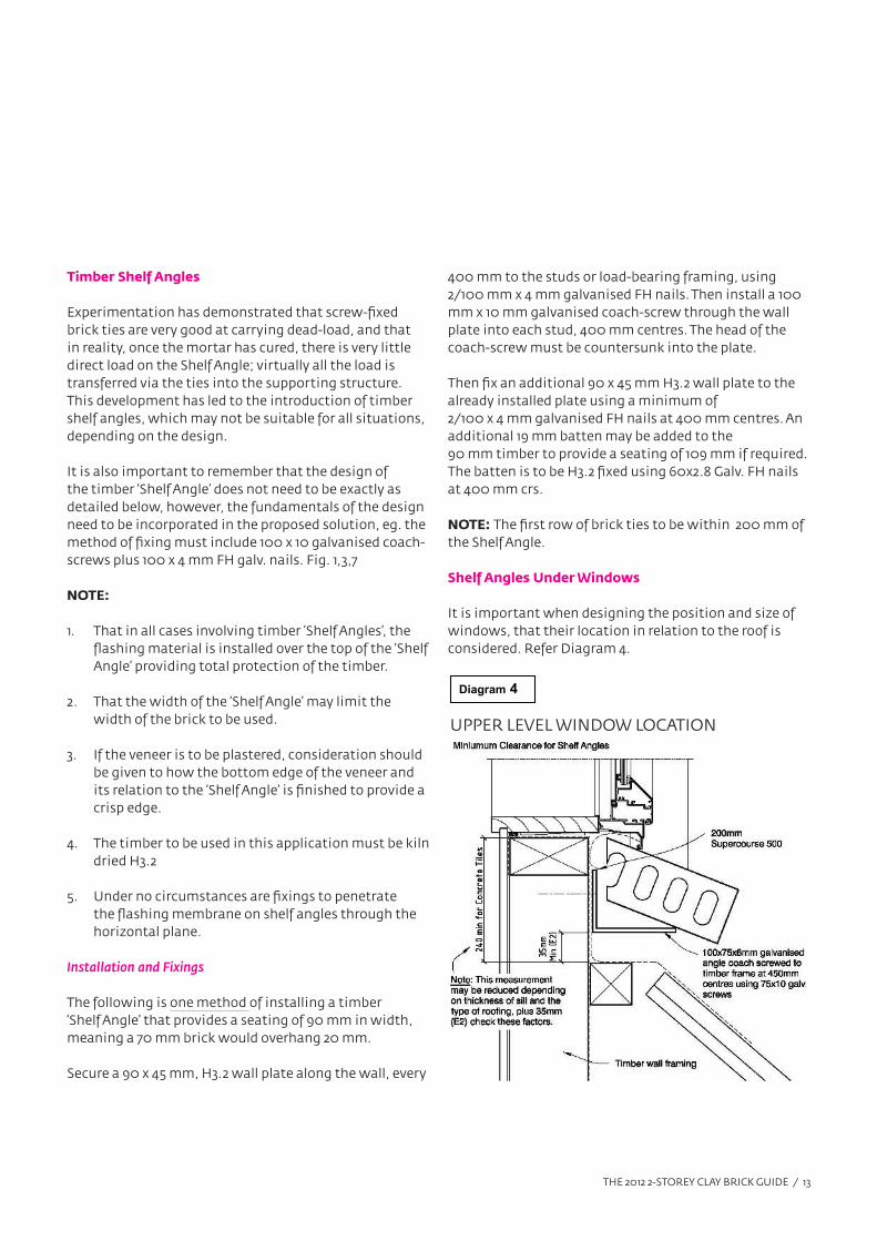
Shelf Angles Under Windows
It is important when designing the position and size of
windows, that their location in relation to the roof is
considered. Refer Diagram 4.
Diagram 4
UPPER LEVEL WINDOW LOCATION
THE 2012 2-STOREY CLAY BRICK GUIDE / 14
A minimum clear distance of 240 mm should be allowed
for between the roof and the base of the window. This
is to allow for adequate fixing of the masonry and to
accommodate the window sill.
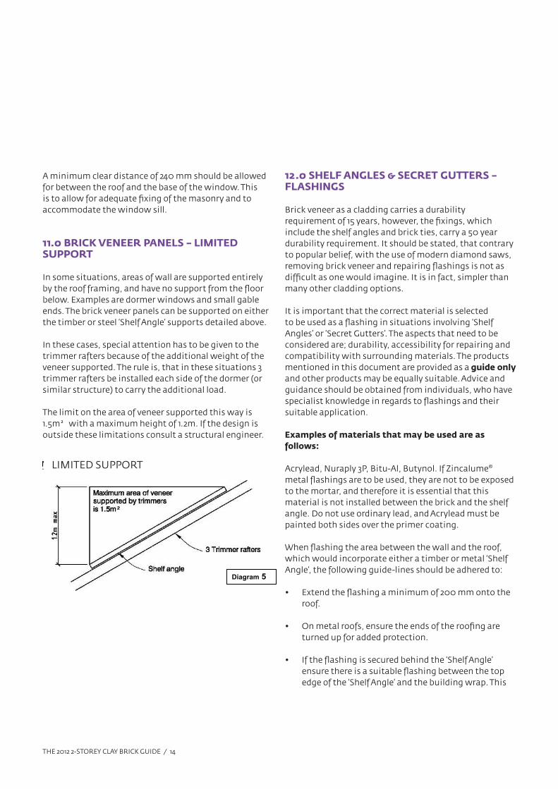
11.0 BRICK VENEER PANELS – LIMITED SUPPORT
In some situations, areas of wall are supported entirely
by the roof framing, and have no support from the floor
below. Examples are dormer windows and small gable
ends. The brick veneer panels can be supported on either
the timber or steel ‘Shelf Angle’ supports detailed above.
In these cases, special attention has to be given to the
trimmer rafters because of the additional weight of the
veneer supported. The rule is, that in these situations 3
trimmer rafters be installed each side of the dormer (or
similar structure) to carry the additional load.
The limit on the area of veneer supported this way is
1.5m² with a maximum height of 1.2m. If the design is
outside these limitations consult a structural engineer.
Diagram 5
LIMITED SUPPORT
12.0 SHELF ANGLES & SECRET GUTTERS – FLASHINGS
Brick veneer as a cladding carries a durability
requirement of 15 years, however, the fixings, which
include the shelf angles and brick ties, carry a 50 year
durability requirement. It should be stated, that contrary
to popular belief, with the use of modern diamond saws,
removing brick veneer and repairing flashings is not as
difficult as one would imagine. It is in fact, simpler than
many other cladding options.
It is important that the correct material is selected
to be used as a flashing in situations involving ‘Shelf
Angles’ or ‘Secret Gutters’. The aspects that need to be
considered are; durability, accessibility for repairing and
compatibility with surrounding materials. The products
mentioned in this document are provided as a guide only
and other products may be equally suitable. Advice and
guidance should be obtained from individuals, who have
specialist knowledge in regards to flashings and their
suitable application.
Examples of materials that may be used are as
follows:
Acrylead, Nuraply 3P, Bitu-Al, Butynol. If Zincalume®
metal flashings are to be used, they are not to be exposed
to the mortar, and therefore it is essential that this
material is not installed between the brick and the shelf
angle. Do not use ordinary lead, and Acrylead must be
painted both sides over the primer coating.
When flashing the area between the wall and the roof,
which would incorporate either a timber or metal ‘Shelf
Angle’, the following guide-lines should be adhered to:
• Extend the flashing a minimum of 200 mm onto the
roof.
• On metal roofs, ensure the ends of the roofing are
turned up for added protection.
• If the flashing is secured behind the ‘Shelf Angle’
ensure there is a suitable flashing between the top
edge of the ‘Shelf Angle’ and the building wrap. This
THE 2012 2-STOREY CLAY BRICK GUIDE / 15
could be an approved flexible flashing tape or a 200
mm wide polyethylene flashing with another layer of
building wrap covering the whole flashing detail.
• A Zincalume® metal flashing may be used under a
‘Shelf Angle’ provided the junction between the up-
stand of the angle and the building wrap is correctly
flashed as described above.
• Where a flashing material that requires support,
spans a distance in excess of 40 mm, provide a packer
to afford support for the flashing material, unless
metal.
• Materials used for flashing must comply with section
4.3 E2/AS1 list of approved flashing materials.
Bottom of Sloping Shelf Angles –
Kickout Flashings/Stop-ends
In regards to weathertightness and the flashing of any
part of a brick veneer, the simple question must be asked;
‘Where does the water go?’ Water passes through the bricks,
runs down the inside face – what happens to it then?
This is especially relevant in situations involving sloping
‘Shelf Angles’. The water runs down the angle discharging
at the bottom. If the angle is less than 1.2m in length and
the area of veneer reasonably well protected, the minor
discharge could be easily handled by the cavity below,
provided it is not close or discharging onto a window or
door head.
However, in most cases, the capture of this water is
important and the best method is to install a plastic or
metal stop-end or kick-out flashing to either discharge
the water into the gutter system or on to the roof. There
are several ways this can be achieved, and an example
of a large and small ‘Stop-end’, which both come in a left
and right hand configuration, are the Gerard Stop-End
and the Ardex BT700/BT701 Kick-out Flashing. (Refer to
Fig’s 5 & 6)
NOTE: Where an opening in the veneer is such that it
would allow birds access to the cavity, it is important to
bird-proof this area.
13.0 PLASTERING
The two storey system outlined in Design Note TB1, may be
plastered. When plaster and paint are applied to a brick
veneer cladding, it takes a system that already manages
water superbly, and waterproofs it.
The maximum weight of the plastered veneer is
restricted to 180 kg/m² which does not exceed the
maximum weight for a “Heavy Weight” cladding specified
in NZS3604, which is 220 kg/m². It should also be
remembered that a plastered/painted veneer holds no
water compared to a saturated face veneer, which could
weigh around 10% more when saturated than dry.
It is recommended, that thin modified plaster coatings
be used. Avoid plaster coatings that are greater than
15 mm in thickness where practical to do so. Plaster
coatings must not exceed 20mm in thickness.
It is important to research and provide a comprehensive
specification when plastering clay brick veneers, to
provide an excellent finish and avoid potential cracking.
The following are a few important considerations.
• Bricks must be laid to a high standard specification.
• Control joints to be installed in high risk areas.
• Veneers with plaster coatings exceeding 15mm in
thickness to have Control Joints through the bricks
and the plaster coating at all corners and in the
centre of walls of lengths greater than 8.0m that do
not contain openings.
• Tie the top row of bricks well.
• Good site management of the veneer is important
to avoid damage by other trades people through
impact.
• Do not touch the veneer for at least 7 days after
installation.
• It is recommended to install ‘Bricklock STR’ and
‘Bricklock CNR’ joint reinforcement or similar, every
THE 2012 2-STOREY CLAY BRICK GUIDE / 16
800 mm up the height of the veneer, but not in the
same joints as the brick ties.
NOTE: This system also covers two storey brick veneers,
that are either ‘painted’ or ‘bagged.’
14.0 MORTAR
The earthquake performance of brick veneer is
dependant on the quality and strength of the mortar that
holds the whole system together. Recent testing of site
mixes has raised some concerns regarding the strengths
of these mortar mixes. The NZ Standards call for 12.5
MPa in structural brickwork without stating a specific
strength in standard veneers. In two storey brick veneers,
the strength of the mortar cannot be compromised. It is
essential that the mortar can be relied upon to achieve a
strong dowelling effect between the bricks.
IMPORTANT: The mortar to be used on all brick veneers,
that are using this system, Design Note TB1, are to be
either mixed to a ratio of 4 sand to 1 cement or must be
factory manufactured bagged trade mortars, to ensure
that the strength of the mortar can be relied upon. It is
recommended that bagged trade mortar’s be specified for
their controlled quality.
15.0 BRICKLAYING
This document is designed to explain the two storey
clay brick system, not to provide in depth detail on
how to lay bricks, and what is good trade practice.
These aspects are covered in other relevant technical
literature and NZ Standards. However, a few important
requirements are mentioned.
• The quality of the bricklaying is important. There
should be no difference regardless of whether it is
being plastered or not.
• Mortar joints should be specified as 10 mm thick, and
should be within +/- 2 mm and are not to exceed +/- 3
mm.
• The bonding of ‘Standard’ bricks may be a third bond
(metric bond). All non-standard sized bricks must be
half-bonded. Refer 1.0 Design Limitations.
• Ensure the bricks are well blended and the bricks kept
dry during the laying process; ie. not saturated.
• The top brick of all veneers is to be tied in every
second perpend joint. Where practical to do so,
install vent holes in the second row from the top of
the veneer to avoid weakening the top row. Refer
Fig.18
Joint Reinforcement
It is recommended, that within the top 2.0m of the brick
veneer, two mortar courses not containing brick ties, and
spaced approximately 800 mm apart, contain ‘Bricklock
STR’ and ‘Bricklock CNR’ joint reinforcement or similar
galvanised wire joint reinforcement. This addition will
provide further strength to the veneer, and provide
redundancy to help prevent any future cracking, and a
degree of insurance during future seismic events.
Control Joints
When constructing houses clad in clay bricks, movement
control joints are unnecessary under normal building
conditions. Clay bricks may expand slightly, but
the degree of expansion is so small, that to current
knowledge, it has never presented a problem. Cracking
in clay brick veneer invariably presents no issues to do
with weathertightness or structural performance – it is a
cosmetic issue.
It should be noted, that ‘Control Joints’ are not required
in clay brick veneers where the floor slab and foundations
are constructed on expansive clays; provided the
foundations have been correctly designed.
However, when constructing a wall cladding system
where a rigid structure is tied to a flexible structure,
common-sense must always apply. Should a situation
arise where there is a high probability of significant
movement occurring between adjacent veneers, e.g.
change in foundation design; small panels bonded to
THE 2012 2-STOREY CLAY BRICK GUIDE / 17
large panels etc, consideration should always be given
to separating the veneer panels with a vertical control
joint. This joint is generally 10 mm wide, but under some
situations it may only require a saw cut in the brick, butt
jointed, which is more discreet. In veneers, a Control
Joint is in effect a controlled crack.
The veneer must be tied to the timber within 200 mm
of each side of the control joint in the same manner
in which an opening is treated, therefore must be
considered at the design stage to ensure timber is
installed in the location required.
16.0 DESIGN ASPECTS
Good design and specifications can simplify the building
process, reduce costs, shorten construction time-
frames, and ultimately provide a rewarding outcome.
The following aspects of the design need careful
consideration.
Decks, verandas and attachments
The simple rule with any attachment to a brick veneer
dwelling, such as a deck, veranda, portico etc, especially
on a two storey dwelling, is to build the structure, design
and install support brackets to the framing, lay the bricks
to full veneer height around the brackets, and finally
attach the proposed external structure to the support
brackets.
There are significant benefits in following the above
procedure. It simplifies the bricklaying, reducing costs in
the process. It avoids complex flashings allowing water
to pass through the veneer at any height and exit via the
weep holes. The installation of steel support brackets,
that span the veneer, provide a fixing point for temporary
scaffold, and transfer the load back to the structural
frame.
An alternative to the above concept is to keep structures
like decks completely independent of the main structure
and free-standing.
Lintels – Window and Door Openings
Careful consideration to the method by which the brick
veneer across the head of openings is supported, is
required at the design stage.
One of the 4 following fundamental methods may be
used.
Method 1 – Traditional Steel Angle – Fig. A
The galvanised steel angle spans from one side of the
opening to the other and sits on the brick veneer forming
a bridge upon which the bricks may be laid. On openings
up to and including 2.0 m, a seating of 100 mm each side
is required. On openings over 2.0 m, a seating of 200 mm
is required. What is important is that the steel angle is
kept completely free of the framing. Prop all lintels for a
min. of 7 days.
Recent seismic testing by BRANZ has demonstrated
that the performance of the brick ties in managing loads
means the size, spans of angle and amount of brick
carried, can be simplified. The following table may be
used for both 70 and 90 mm bricks, and the height of the
veneer supported is not important.
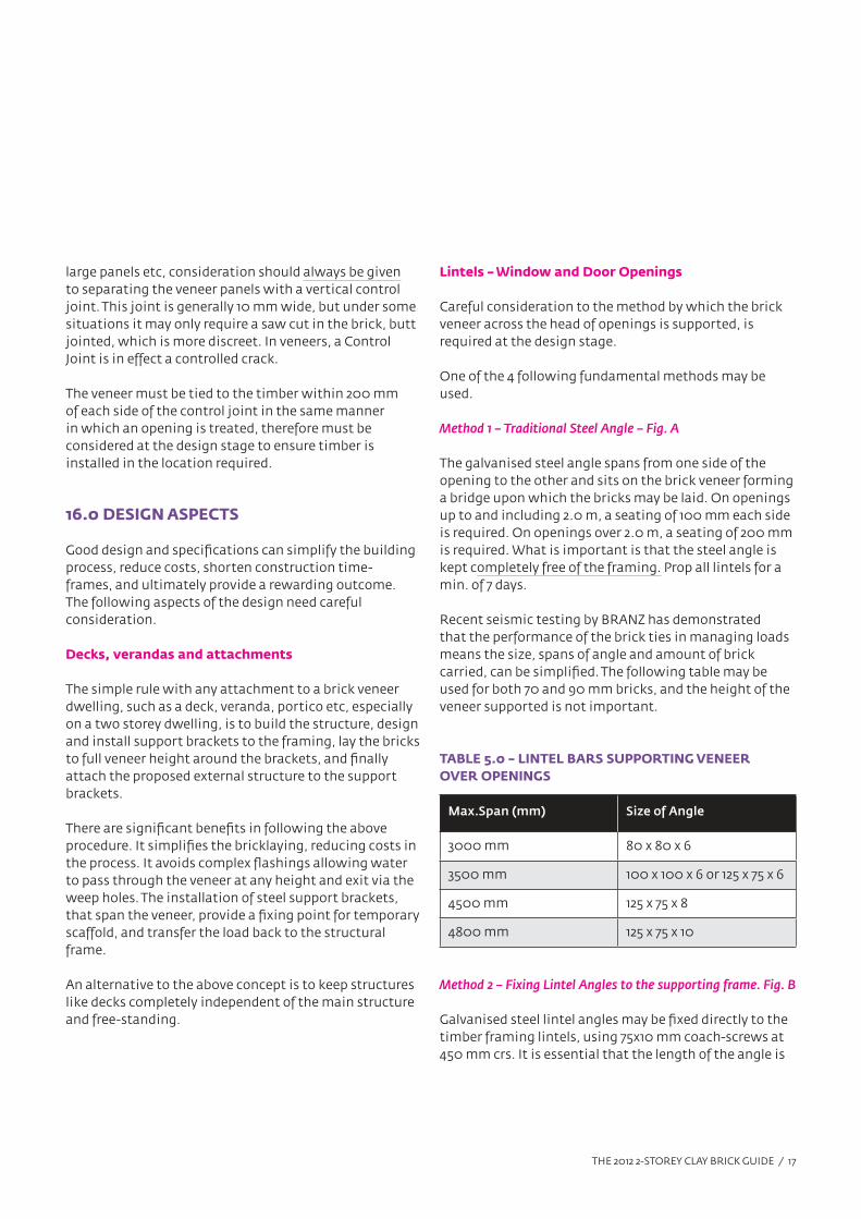
TABLE 5.0 – LINTEL BARS SUPPORTING VENEER
OVER OPENINGS
Max.Span (mm) Size of Angle
3000 mm 80 x 80 x 6
3500 mm 100 x 100 x 6 or 125 x 75 x 6
4500 mm 125 x 75 x 8
4800 mm 125 x 75 x 10
Method 2 – Fixing Lintel Angles to the supporting frame. Fig. B
Galvanised steel lintel angles may be fixed directly to the
timber framing lintels, using 75x10 mm coach-screws at
450 mm crs. It is essential that the length of the angle is
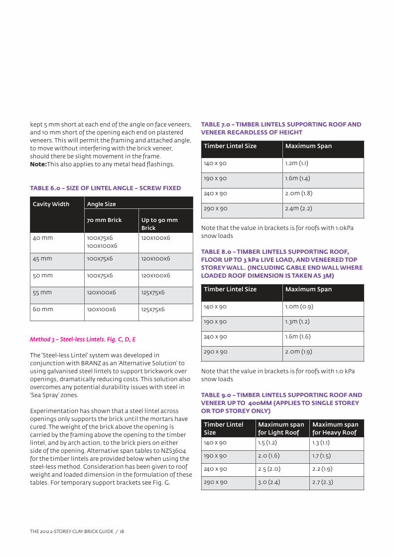
THE 2012 2-STOREY CLAY BRICK GUIDE / 18
kept 5 mm short at each end of the angle on face veneers,
and 10 mm short of the opening each end on plastered
veneers. This will permit the framing and attached angle,
to move without interfering with the brick veneer,
should there be slight movement in the frame.
Note:This also applies to any metal head flashings.
TABLE 6.0 – SIZE OF LINTEL ANGLE – SCREW FIXED
Cavity Width Angle Size
70 mm Brick Up to 90 mm
Brick
40 mm 100x75x6
100x100x6
120x100x6
45 mm 100x75x6 120x100x6
50 mm 100x75x6 120x100x6
55 mm 120x100x6 125x75x6
60 mm 120x100x6 125x75x6
Method 3 – Steel-less Lintels. Fig. C, D, E
The ‘Steel-less Lintel’ system was developed in
conjunction with BRANZ as an ‘Alternative Solution’ to
using galvanised steel lintels to support brickwork over
openings, dramatically reducing costs. This solution also
overcomes any potential durability issues with steel in
‘Sea Spray’ zones.
Experimentation has shown that a steel lintel across
openings only supports the brick until the mortars have
cured. The weight of the brick above the opening is
carried by the framing above the opening to the timber
lintel, and by arch action, to the brick piers on either
side of the opening. Alternative span tables to NZS3604
for the timber lintels are provided below when using the
steel-less method. Consideration has been given to roof
weight and loaded dimension in the formulation of these
tables. For temporary support brackets see Fig. G.
TABLE 7.0 – TIMBER LINTELS SUPPORTING ROOF AND
VENEER REGARDLESS OF HEIGHT
Timber Lintel Size Maximum Span
140 x 90 1.2m (1.1)
190 x 90 1.6m (1.4)
240 x 90 2.0m (1.8)
290 x 90 2.4m (2.2)
Note that the value in brackets is for roofs with 1.0kPa
snow loads
TABLE 8.0 – TIMBER LINTELS SUPPORTING ROOF,
FLOOR UP TO 3 kPa LIVE LOAD, AND VENEERED TOP
STOREY WALL. (INCLUDING GABLE END WALL WHERE
LOADED ROOF DIMENSION IS TAKEN AS 3M)
Timber Lintel Size Maximum Span
140 x 90 1.0m (0.9)
190 x 90 1.3m (1.2)
240 x 90 1.6m (1.6)
290 x 90 2.0m (1.9)
Note that the value in brackets is for roofs with 1.0 kPa
snow loads
TABLE 9.0 – TIMBER LINTELS SUPPORTING ROOF AND
VENEER UP TO 400MM (APPLIES TO SINGLE STOREY
OR TOP STOREY ONLY)
Timber Lintel
Size
Maximum span
for Light Roof
Maximum span
for Heavy Roof
140 x 90 1.5 (1.2) 1.3 (1.1)
190 x 90 2.0 (1.6) 1.7 (1.5)
240 x 90 2.5 (2.0) 2.2 (1.9)
290 x 90 3.0 (2.4) 2.7 (2.3)
THE 2012 2-STOREY CLAY BRICK GUIDE / 19
Note:
1. That the value in brackets is for roofs with 1.0kPa
snow loads.
2. That Tables 7, 8 & 9 apply to 70 and 90 mm bricks
Although not essential, it is recommended that bricks
be laid in a ‘Soldier Course’ manner across openings.
The following specification must be adhered to:
• Temporary support must remain in place for a
minimum of 7 days.
• Where openings are over 1200 mm and the brickwork
depth above the opening exceeds 300 mm, ‘Bricklock
STR’ joint reinforcement or similar galvanised wire
joint reinforcement, is to be installed within 400
mm of the underside of the brickwork and extend
200 mm each side of the opening.
• A gap of 5 mm – 10 mm is to be left between the
underside of the brickwork and the top of the metal
flashing.
Brick Ties
• Standard soldier course bricks are to be tied every
2nd perpend with 2 brick ties spaced 150 mm apart.
Double height bricks as soldiers tied every vertical
perpend with 2 ties.
• In Standard stretcher bond – 1 tie on edge every 230
mm in the bottom two rows of bricks. The ties to be
positioned in the perpend mortar joints.
• Note: Minimum depth for Soldier Course bricks or
double height bricks is 160 mm. Minimum depths in
stretcher bond for standard height bricks is 240 mm.
Method 4 – Precast Reinforced Clay Lintels
Some clay brick companies manufacture and market
a ‘Precast Reinforced Clay Lintel’ for use on clay brick
veneers, if they are to be plastered.
They are normally 162 mm x 90 mm and are engineered
to span up to 2800 mm openings. If you are interested
in exploring this option, contact the brick company
concerned to obtain information on availability and any
limitations to the use of this method.
17.0 TECHNICAL SUPPORT
The information contained in this brochure should
satisfy most situations in regards to the installation of
two storey brick veneers covered by Design Note TB1.
However, should you require additional help or guidance,
contact any of the following companies for assistance.
Please note: Where the make of brick has been specified,
please contact the company involved for their assistance.
Austral Bricks 0800 287 8725
Canterbury Clay Bricks 03 318 8203
Clay Bricks Ltd 07 828 9919
Monier Bricks 0800 507 600
NOTE: Steel Framed Construction
Two storey brick veneer dwellings may be constructed using light gauge steel framing; however specific engineering
design (S.E.D) is required for the framing in relation to the brick veneer. Specific details are also required to cover
fixings, shelf angles etc. www.nashnz.org.nz
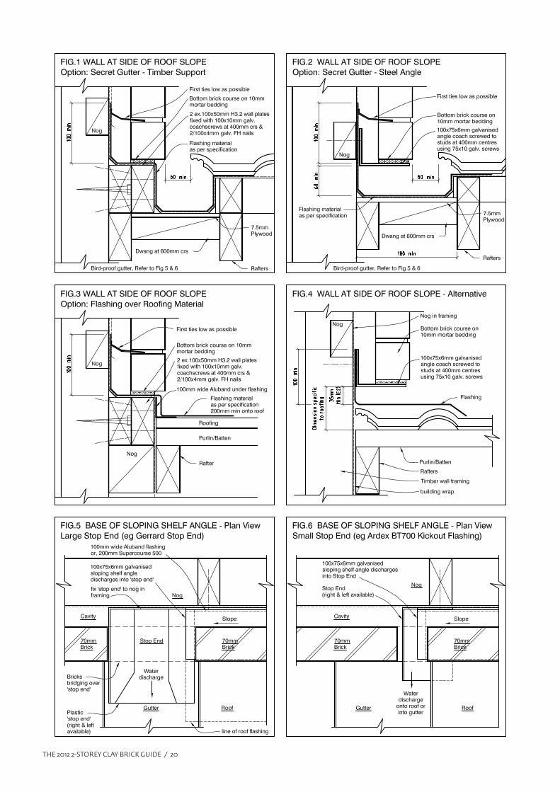
THE 2012 2-STOREY CLAY BRICK GUIDE / 20
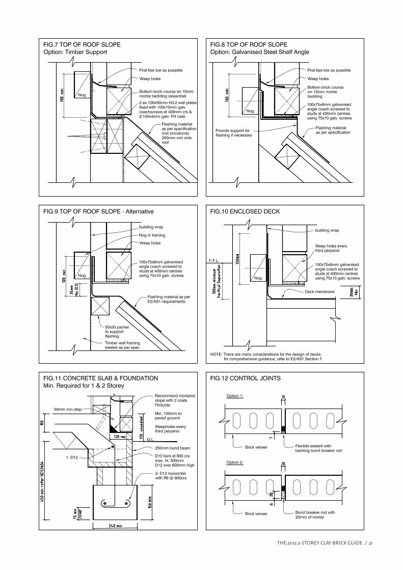
THE 2012 2-STOREY CLAY BRICK GUIDE / 21
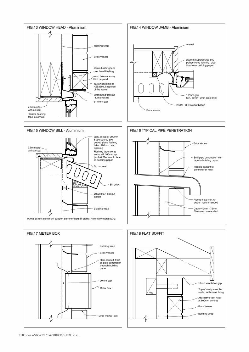
THE 2012 2-STOREY CLAY BRICK GUIDE / 22
weep holes at every
third perpend

THE 2012 2-STOREY CLAY BRICK GUIDE / 23
60-70
10
Additional building wrap
extended up to nearest lap
above, or flashing tape
Additional building wrapextended up to nearest lapabove, or flashing tape
2 brick ties everysecond perpend
5 - 10mm gap essential
Nog if requiredfix to NZS3604
Aluminium or zincalume
flashing
Building wrap
brick veneer
If the bricks are laid in this manner, the centre holes will be visible.
A 'slip' may be glued underneath to hide the holes, but allow for this if
not plastered
Brick ties every perpendbottom 2 rows
5 - 10mm gap essential
Nog if requiredfix to NZS3604
Aluminium orzincalume flashing
brick veneer
2 brick ties everysecond perpend
Nog if requiredfix to NZS3604
Aluminium or zincalume flashing
Notes:
1. Flashing to be aluminum or zincalume.
2. Flashing may require packing out to suit.
3. Recommended on all windows.
4. Nail to timber framing with galv. flat head clouts, building
wrap lapped over flashing, or fit flexible flashing tape.
5. The 10mm flashing leg to be positioned on external side
of aluminum/window extrusion.
Fig F. Head Flashing
5 - 10mm gap essential
Fig E. Double Height Brick
Fig C. Steel-less Lintel- Standard Stretcher
Fig A. Lintel- Traditional Fig B. Lintel- Fixed to framing
Fig D. Steel-less Lintel- Soldier Course
Do not attach lintel totimber frame.
Seating on bricks;100mm up to 2.0m200mm over 2.0m
Lintel coach-screwed totimber framing using75 x 10 screws @ 400 crsLintel bar to be 5-10mmshort of opening each end.
LINTEL OPTIONS TO SUPPORT BRICKS OVER OPENINGS
Refer table forangle size
Refer table forangle size
Do not put in mortar course
Openings over 1200mm-Bricklock STR extending200mm each side withinbottom 400mm of veneer
Openings over 1200mm-Bricklock STR extending200mm each side withinbottom 400mm of veneer
Openings over 1200mm-Bricklock STR extending200mm each side withinbottom 400mm of veneer
THE 2012 2-STOREY CLAY BRICK GUIDE / 24
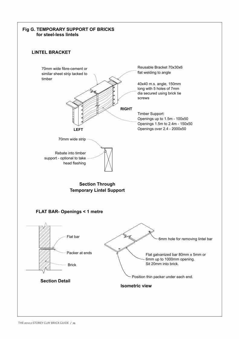
Reusable Bracket 70x30x6
flat welding to angle
40x40 m.s. angle, 150mm
long with 5 holes of 7mm
dia secured using brick tie
screws
6mm hole for removing lintel bar
Flat galvanized bar 80mm x 5mm or
6mm up to 1000mm opening.
Sit 20mm into brick.
Position thin packer under each end.
Flat bar
70mm wide fibre-cement or
similar sheet strip tacked to
timber
Timber Support:
Openings up to 1.5m - 100x50
Openings 1.5m to 2.4m - 150x50
Openings over 2.4 - 2000x50
70mm wide strip
Rebate into timber
support - optional to take
head flashing
Packer at ends
Brick
Fig G. TEMPORARY SUPPORT OF BRICKS for steel-less lintels
RIGHT
LEFT
Section Through
Temporary Lintel Support
Section Detail
FLAT BAR- Openings < 1 metre
LINTEL BRACKET
Isometric view
THE 2012 2-STOREY CLAY BRICK GUIDE / 25
BRICKLAYING SPECIFICATION FOR TWO STOREY CLAY BRICK VENEERS
1.0 PRELIMINARY
Refer to the Preliminary and General Clauses of
this specification and to the General Conditions of
Contract, which are equally binding on all trades.
All persons involved in the installation of this
brick veneer must be aware of all aspects of this
specification.
1.1 SCOPE
This section of the contract consists of the supply
and laying of all brick veneer work veneer indicated
on the drawings and specified herein and all
associated lintels, ties etc. required for a complete
contract.
1.2 WORKMANSHIP
Bricklaying shall be carried out by qualified
tradesmen employed by a contractor specialising
in the laying of brick. Bricklaying materials and
workmanship shall conform in all respects to all the
relevant requirements of NZ Standards and other
relevant documents.
1.3 RELATED DOCUMENTS
In this section of the specification, reference
is made to the latest revisions of the following
documents:
AS/NZS 4455:1997 Masonry Units and Segmental
Pavers
NZS 3602:2003 Timber and Wood Based
Products for use in Building
NZS 3604:1999 Timber Framed Buildings
(SANZ)
NZS 4210:2001 Masonry construction:
materials and Workmanship
(SANZ)
NZS 4230:2004 Design of Masonry Structures
(SANZ)
AS/NZS 1170 Structural Design Actions
NZS 1170.5:2004 Structural Design Actions
–Earthquake Action- New
Zealand
NZS4229: 1999 Masonry Buildings not
requiring Specific Design
NZS HB 4236 Masonry Veneer Wall Cladding –
Summary of all Standards
relating to brick veneer
NZBC B1/AS1 Structure – General, 2.0
Masonry
AS/NZS 2699.1 Built-in components
for masonry
construction-Wall ties
AS/NZS 2699.3 Built-in components for
masonry construction – Lintels
and Shelf Angles
NZS 3103 Sands for mortars and plasters
BRANZ Bulletin 436 Masonry Veneer construction
1.4 MANUFACTURER’S DOCUMENTS
In addition to this document, Design Note TB1,
any manufacturer’s and supplier’s documents or
brochures relating to brick and bricklaying shall
apply.
2.0 PRODUCTS
2.1 General
All materials shall be the best of their respective
kinds free from impurities, imperfections and other
faults likely to impair the finished walls.
Materials
2.2 Bricks
Bricks shall be first quality clay bricks manufactured
to comply with AS/NZS 4455. The bricks are to be the
size and brand specified by the owner/architect/
builder and must be either manufactured or
marketed by a member of the NZCB&PMA or have
Appendix – Design Note TB1
THE 2012 2-STOREY CLAY BRICK GUIDE / 26
their approval to use their system.
2.3 Mortar
Shall be manufactured from cement, sand, lime and
additives complying with the relevant standards in
NZS 4210:2001. Good mortar strength is essential.
All mortar used to lay bricks on this contract is to be
a pre-bagged factory manufactured ’ Trade Mortar’
or site mixed at a ratio of 4 sand to 1 cement. Water
and plasticizing agents are to be added to conform
to the mortar manufacturer’s specification.
2.4 Lintels and Shelf Angles
All steel lintels and shelf angles are to be galvanised
and to comply with AS/NZS 2699.3. In Sea Spray
Zones epoxy coated, or stainless steel.
Lintels are to be sized to comply with the table in
Design Note TB1 or as specified by the structural
engineer.
Where lintels span from one side of the veneer to
the other in the traditional manner, the seating
each side is to comply with NZS 3604 . Cl 11.7.6.2 and
not be attached in any way to the framing.
Where the lintels are specified as being attached
to the framing by way of galvanised bolts or coach
screws, the steel lintel must be kept completely
free of the brickwork and 5 mm short for face brick,
10 mm for plastered veneers, of the opening width
each side of the opening.
2.5 Damp-proof course - opening flashings
Thermakraft ‘Supercourse 500’ polyethylene,
200 mm wide flashing, used to flash around all
openings. The flashings are to be held off the
building wrap using a 20 mm kick-out batten, or
galvanised clouts left proud, allowing moisture to
drop into the cavity. Flashings to extend 200 mm
past openings in all directions.
COMPONENTS
2.6 Metal Brick Ties
Brick ties, manufactured to AS/NZS2699.1, are to be
used on this veneer. The ties must be of sufficient
length to ensure a minimum of 50% bedding in the
mortar course. Refer to tables in Design Note TB1 for
tie length. Ties are to be Stainless Steel in Sea Spray
Zones epoxy coated, or stainless steel.
2.7 Reinforcement
Eagle Wire Products Ltd ‘Bricklock STR 2.0 m and
Bricklock CNR’s.’ or similar galvanised reinforcing
wire.
ACCESSORIES
2.8 Colouring Pigments
Use oxides to colour mortar where specified. This
is to be added by volume and the architect or his
agent advised of the quantity to be used to ensure
consistency in the mortar colour.
2.9 Bitumen Damp-proof Membrane
The edge of slab and cavity are to be coated with 2
coats of bitumen emulsion, to architect’s approval.
Glued membrane d.p.c permitted.
3.0 BRICKLAYING
IMPORTANT:
The bricklayer will be required to lay up a sample
panel of the bricks, approx. 1.0 m square to
demonstrate spread of colour (if laid as a face brick)
and the mortar joints expected on the contract. If
a ‘bagged’ finish is required, the sample panel will
be used to demonstrate the finish to the architect’s
approval.
3.1 Tolerances
The brick veneer is not to exceeed the maximum
tolerances given in Table 2.2 NZS 4210.
3.2 Wet Weather
Keep all bricks on site dry so they do not become
saturated. Keep the tops of pallets covered, bricks
stacked around the site covered and the top of
uncompleted veneers covered. This requirement
applies during any inclement weather or when the
job has been left for the day. All brick veneer must
be fully protected from rain for a period of 6
THE 2012 2-STOREY CLAY BRICK GUIDE / 27
hours after the bricks have been laid. Divert all
down-pipes away from discharging water onto the
veneer.
3.3 Protection of the Brick Veneer
The brick veneer is to be protected from damage
and staining due to mortar, dirty water, paints and
other chemicals at all times. Where necessary, the
entire veneer is to be covered in polythene in order
to protect it from contamination from building
activities above and surrounding the veneer. Care
is to be taken with the handling of scaffold and
scaffold planks so as not to impact on the brick
veneer. NOTE: The builder must straighten
the frame prior to the bricks being laid to avoid
excessive impact on the veneer.
3.4 Blending of the Bricks
IMPORTANT
(Applies if the veneer is to be laid as a face veneer)
The final appearance of the brickwork on this
project is of the utmost importance and therefore
will be inspected on a regular, sometimes on a
daily basis, by the architect or his agent to ensure
an acceptable standard of laying is achieved and
maintained. Unacceptable bricklaying in the
opinion of the architect or his agent will be removed
and replaced at the expense of the bricklaying
contractor.
All pallets shall be checked by the bricklayer on
site for colour, batch number and quality, prior
to commencing any laying. Any problems with
the product must be sorted out with the supplier
before the bricks are laid.
The bricks must be laid from at least three pallets
where practical, to provide an even spread of
colour over the total area of the wall. Do not lay
any bricks, which have obvious defects. In the
event this occurs or blending is NOT satisfactory,
based on the opinion of the architect or his agent,
the bricks concerned will be removed and replaced
at the bricklayers cost.
Bagged Brickwork
Where the brickwork is to be bagged and painted,
the quality of the brick laying must be to face brick
finish as contained within this specification. The
only variation to this requirement is the blending of
the bricks, which is of no importance.
The degree of smearing of mortar over the face
of the bricks is to be agreed upon between the
architect, owner and the bricklayer, prior to the
work commencing and should be considered a trial
and error process in the initial stages of the contract
to establish the finished appearance the architect
requires.
3.5 Bonding of the Brickwork
Bricks shall be laid dry, in stretcher bond, with a
half-bond pattern unless other wise specified by the
architect. Bricks shall not be stack-bonded apart
from minor detailing. The minimum length of a
piece of brick to be laid shall be no less than 60 mm.
Soldier Courses
Bricks are to be laid as ‘Soldier Courses’ as and
where specified on the Working Drawings or as
directed by the architect. The bricks are to be laid
perpendicular, evenly spaced and to be of an even
thickness. Soldier bricks are to be tied every 2nd
perpend joint to the structure. For double height
bricks this shall be every perpend.
3.6 Mortar, Mortar joints and Pointing
All bricks shall be fully bedded in mortar.
All joints shall be 10 mm, +/- 2 mm, both horizontally
and vertically (perpends) and shall be consistent in
thickness. No joint may be less than 7 mm or more
than 13 mm; joints of these thicknesses should be
the exception and certainly less than 5% of the total
number of joints.
Mortar must be mixed by volume unless bagged.
All joints may be raked to a depth of 5 mm and
must not exceeding 6 mm - tooled smooth. The
tooling of the joint is to be done when the mortar is
capable of retaining a finger print – this is to ensure
consistency in the colour of the mortar.
However, where a ‘Bagged’ finish is specified
the joint shall be finished flush to the architect’s
satisfaction.
IMPORTANT: If the air temperature exceeds
27º C or if there are warm winds blowing, common
THE 2012 2-STOREY CLAY BRICK GUIDE / 28
in coastal areas, the bricks are to be lightly
wetted and mortar cured over 48 hours to ensure
‘Hydration’ has occurred.
3.7 Brick Cavity
Form wall cavity between structural wall and brick
veneer (minimum 40 mm – maximum 60 mm)
and maintain cavity dimension indicated on the
drawings; recommend 50 mm. Ensure the cavity
is maintained clean of mortar droppings and clean
mortar off ties as the work proceeds. Clean off
mortar daggs and protrusions from the cavity face
in order that the mortar does not encroach more
than 5 mm into the cavity. It is essential that care
be taken at this stage to avoid any bridging of the
cavity. Ensure the brick cavity is sealed off from any
roof space.
Take particular care to maintain a clean cavity.
Clean out openings (wash-outs) shall be provided
along the base, every 10th brick and at corners.
This will apply on all levels and above Shelf Angles.
Ensure that brickwork at lower levels is protected
and thoroughly cleaned of mortar washings from
upper levels on a daily basis.
3.8 Weep and Vent Holes
Form weep holes in the bottom course of walls at
ground level, and wherever the cavity is closed at
the base. Weep holes shall be formed every third
perpend (or 1000 sqmm/lineal metre of wall)
and shall be clean and free of mortar and other
restrictions.
The above requirement shall apply equally for vent
holes at the top of each section of veneer. The vent
holes are not to be placed in the perpends of the
top row of bricks but at least the next row down (or
as specified) to protect the bonding strength of the
bricks on the top row. In the event that an adequate
gap is left at the top of the veneer, the vent holes
may may be omitted. Refer Fig. 18. If the veneer is
waterproof, this requirement can be reduced by
50%, ie. 500 sqmm’s per lineal metre of wall.
3.9 Brick ties
Brick ties are to be installed at a slope of 5 degrees
at 400 mm centres horizontally into studs and at a
maximum of 400 mm vertically.
Tie sizes shall vary to suit the varying widths of
cavities. Wall tie anchorage shall be a minimum
of half the width of the mortar bed, with 15 mm
minimum cover from the weather face. Additional
ties shall be placed within 200 mm of the edge
around openings.
3.10 Joint reinforcement
It is recommended that galvanised wire joint
reinforcement such as ‘Bricklock STR’ and ‘Bricklock
CNR’ to be installed in the middle of the mortar bed
thickness within the top 2.0 m of theveneer spaced
approximately 800 mm apart and not in the same
course as the ties. In plastered veneers, every 800
mm through the height of the veneer.
3.11 Window and Door Sills
All window and door sills will be laid in order that
they are consistent in slope and overhang, or
alternatively, as detailed on the working drawings.
Sill bricks or tiles will be laid in such a manner that
they are of a similar size in individual width
along the entire width of the window or door sill
opening.
3.12 Cleaning of Brickwork
Clean all face work as the work proceeds using
clean water and sponges. On completion, the
brickwork is to be left in a clean condition, free of
mortar smears and staining. Acid is not to be used
to clean the bricks unless the brick manufacturer,
the architect or his agent gives approval to do so.
The veneer is not to be water-blasted.
Where the veneer is to be ‘bagged and painted’
the cleaning of the veneer is not as critical and
can be left in a condition that is acceptable to the
architect or his agent. This matter can be resolved
at the time of the demonstration panel or at the
commencement of the contract.
Vanadium salt stains (bright green/yellow) if
present, are to be removed by the bricklayer on
completion of the project by washing the bricks
with a solution of Sodium Hydroxide (Caustic Soda)
60gm/litre of water.
Efflorescence – any white salts are to be removed
from the brickwork. Brush with a stiff-bristle broom
THE 2012 2-STOREY CLAY BRICK GUIDE / 29
and take away brushings from the locality. Remove
remaining deposit with a damp sponge. Repeat this
process as necessary through to the completion of
the contract. Note: keeping bricks and brickwork
dry during the construction phase will eliminate
most issues to do with efflorescence.
Where scaffold planks are at an upper level,
brickwork is to be protected from mortar stains and
cleaned on a daily basis to reduce the potential of
mortar stains down the veneer.
3.13 Lintels and Shelf Angles
It is the responsibility of the bricklayer to ensure all
lintels are installed correctly as per plans, details
and specified in Design Note TB1. Ensure durability
requirements are satisfied for the location of the
dwelling.
4.0 FLASHINGS
4.1 Head flashings are to be installed as per drawings.
4.2 Supercourse 500 being 200 mm in width is to be
used to flash around all windows and openings. A 20
mm kick-out batten is to be installed.
4.3 It is the responsibility of the bricklayer to ensure
all flashings are installed as per drawings prior to
bricks being laid in the area concerned.
5.0 CONTROL JOINTS
Control joints, 10 mm wide, are to be installed as
per plans unless otherwise directed by the architect
or his agent, during the progress of the contract.
The joints are to be filled with a flexible sealant of a
similar colour to the mortar.
6.0 INSPECTIONS
All inspections will be carried out by the appropriate
authorities. It is the bricklayer’s responsibility to
call for all necessary inspections involving his trade.
For whatever reason, if a mandatory inspection,
for example, half-height, is not done, it is the
responsibility of the bricklayer to ensure that the
architect or his agent, is advised prior to continuing
work in the area concerned.
IMPORTANT NOTE:
Should there be any conflict between the information in
this ‘General 2 Storey Specification’ and the information
in Design Note TB1, the latter shall always take
precedence.

THE 2012 2-STOREY CLAY BRICK GUIDE / 30
Notes

THE 2012 2-STOREY CLAY BRICK GUIDE / 31
Notes