Embed Size (px)
Citation preview
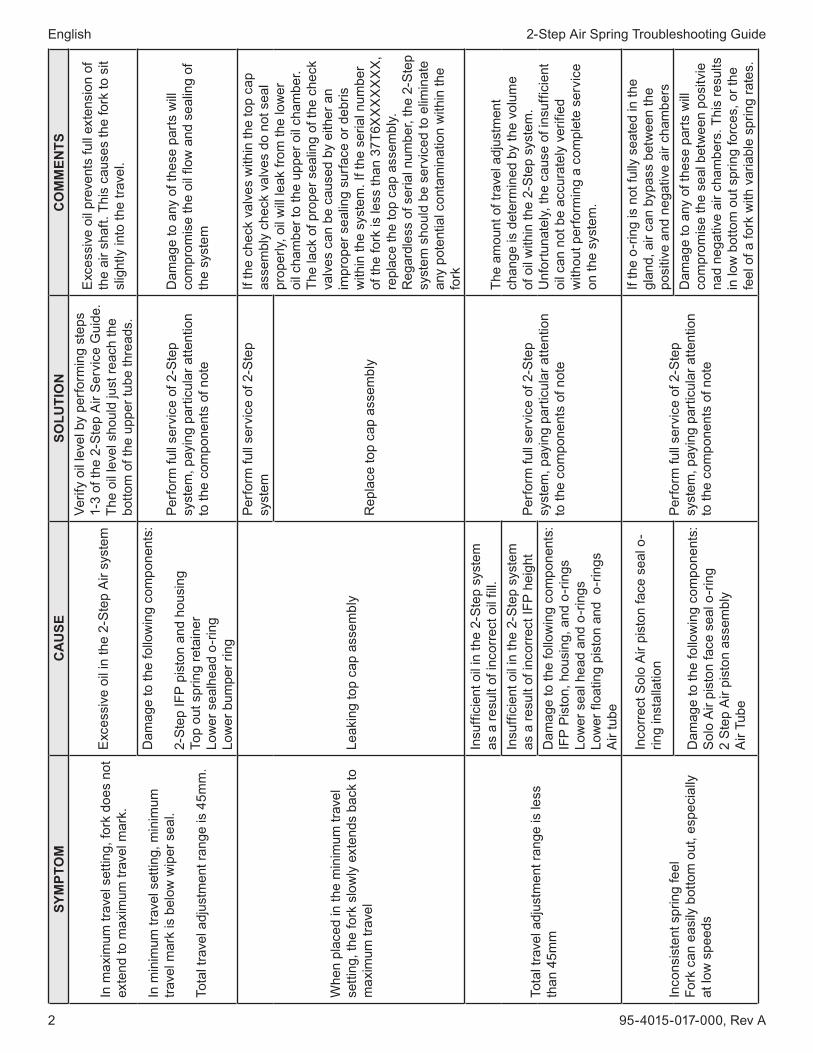
2-Step Air Spring Troubleshooting Guide English
�© SRAM CORPORATION • 2007
2-step air spring troubleshooting guide(lyrik - totem)
introduction
This troubleshooting guide is intended to help in the diagnosis and evaluation of problems occurring on Lyrik and Totem forks equipped with the 2-Step Air spring system. This guide is not intended to replace the comprehensive service instructions available for the 2-Step Air system.
For more information on servicing Lyrik or Totem forks, please reference the links below:Lyrik Spare Parts DiagramTotem Spare Parts Diagram
note: prior to perForming serVice on the 2-step system, please be sure you haVe the most recent and up to date parts. Warning: beFore perForming any serVice, alWays depressuriZe the 2-step air system and remoVe the air ValVes!
English 2-Step Air Spring Troubleshooting Guide
2 95-40�5-0�7-000, Rev A
sym
pto
mc
au
se
solu
tio
nc
om
men
ts
In m
axim
um tr
avel
set
ting,
fork
doe
s no
t ex
tend
to m
axim
um tr
avel
mar
k.
In m
inim
um tr
avel
set
ting,
min
imum
tra
vel m
ark
is b
elow
wip
er s
eal.
Tota
l tra
vel a
djus
tmen
t ran
ge is
45m
m.
Exc
essi
ve o
il in
the
2-S
tep
Air
syst
em
Verif
y oi
l lev
el b
y pe
rform
ing
step
s �-
3 of
the
2-S
tep
Air
Ser
vice
Gui
de.
The
oil l
evel
sho
uld
just
reac
h th
e bo
ttom
of t
he u
pper
tube
thre
ads.
Exc
essi
ve o
il pr
even
ts fu
ll ex
tens
ion
of
the
air s
haft.
Thi
s ca
uses
the
fork
to s
it sl
ight
ly in
to th
e tra
vel.
Dam
age
to th
e fo
llow
ing
com
pone
nts:
2-S
tep
IFP
pis
ton
and
hous
ing
Top
out s
prin
g re
tain
erLo
wer
sea
lhea
d o-
ring
Low
er b
umpe
r rin
g
Perfo
rm fu
ll se
rvic
e of
2-S
tep
syst
em, p
ayin
g pa
rticu
lar a
ttent
ion
to th
e co
mpo
nent
s of
not
e
Dam
age
to a
ny o
f the
se p
arts
will
com
prom
ise
the
oil f
low
and
sea
ling
of
the
syst
em
Whe
n pl
aced
in th
e m
inim
um tr
avel
se
tting
, the
fork
slo
wly
ext
ends
bac
k to
m
axim
um tr
avel
Leak
ing
top
cap
asse
mbl
y
Perfo
rm fu
ll se
rvic
e of
2-S
tep
syst
emIf
the
chec
k va
lves
with
in th
e to
p ca
p as
sem
bly
chec
k va
lves
do
not s
eal
prop
erly,
oil
will
leak
from
the
low
er
oil c
ham
ber t
o th
e up
per o
il ch
ambe
r. Th
e la
ck o
f pro
per s
ealin
g of
the
chec
k va
lves
can
be
caus
ed b
y ei
ther
an
impr
oper
sea
ling
surfa
ce o
r deb
ris
with
in th
e sy
stem
. If t
he s
eria
l num
ber
of th
e fo
rk is
less
than
37T
6XX
XX
XX
X,
repl
ace
the
top
cap
asse
mbl
y.
Reg
ardl
ess
of s
eria
l num
ber,
the
2-S
tep
syst
em s
houl
d be
ser
vice
d to
elim
inat
e an
y po
tent
ial c
onta
min
atio
n w
ithin
the
fork
Rep
lace
top
cap
asse
mbl
y
Tota
l tra
vel a
djus
tmen
t ran
ge is
less
th
an 4
5mm
Insu
ffici
ent o
il in
the
2-S
tep
syst
em
as a
resu
lt of
inco
rrec
t oil
fill.
Perfo
rm fu
ll se
rvic
e of
2-S
tep
syst
em, p
ayin
g pa
rticu
lar a
ttent
ion
to th
e co
mpo
nent
s of
not
e
The
amou
nt o
f tra
vel a
djus
tmen
t ch
ange
is d
eter
min
ed b
y th
e vo
lum
e of
oil
with
in th
e 2-
Ste
p sy
stem
. U
nfor
tuna
tely,
the
caus
e of
insu
ffici
ent
oil c
an n
ot b
e ac
cura
tely
ver
ified
w
ithou
t per
form
ing
a co
mpl
ete
serv
ice
on th
e sy
stem
.
Insu
ffici
ent o
il in
the
2-S
tep
syst
em
as a
resu
lt of
inco
rrec
t IFP
hei
ght
Dam
age
to th
e fo
llow
ing
com
pone
nts:
IFP
Pis
ton,
hou
sing
, and
o-r
ings
Low
er s
eal h
ead
and
o-rin
gsLo
wer
floa
ting
pist
on a
nd o
-rin
gsA
ir tu
be
Inco
nsis
tent
spr
ing
feel
Fork
can
eas
ily b
otto
m o
ut, e
spec
ially
at
low
spe
eds
Inco
rrec
t Sol
o A
ir pi
ston
face
sea
l o-
ring
inst
alla
tion
Perfo
rm fu
ll se
rvic
e of
2-S
tep
syst
em, p
ayin
g pa
rticu
lar a
ttent
ion
to th
e co
mpo
nent
s of
not
e
If th
e o-
ring
is n
ot fu
lly s
eate
d in
the
glan
d, a
ir ca
n by
pass
bet
wee
n th
e po
sitiv
e an
d ne
gativ
e ai
r cha
mbe
rs
Dam
age
to th
e fo
llow
ing
com
pone
nts:
Sol
o A
ir pi
ston
face
sea
l o-r
ing
2 S
tep
Air
pist
on a
ssem
bly
Air
Tube
Dam
age
to a
ny o
f the
se p
arts
will
com
prom
ise
the
seal
bet
wee
n po
sitv
ie
nad
nega
tive
air c
ham
bers
. Thi
s re
sults
in
low
bot
tom
out
spr
ing
forc
es, o
r the
fe
el o
f a fo
rk w
ith v
aria
ble
sprin
g ra
tes.
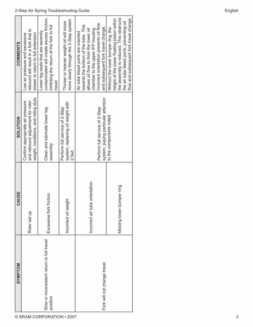
2-Step Air Spring Troubleshooting Guide English
3© SRAM CORPORATION • 2007
sym
pto
mc
au
se
solu
tio
nc
om
men
ts
Slo
w o
r inc
onsi
sten
t ret
urn
to fu
ll tra
vel
posi
tion
Rid
er s
et u
pC
onfir
m a
ppro
pria
te a
ir pr
essu
re
and
rebo
und
adju
stm
ent f
or ri
der
wei
ght,
cond
ition
s, a
nd ri
ding
sty
le
Low
air
pres
sure
and
exc
essi
ve
rebo
und
will
resu
lt in
a fo
rk th
at is
sl
ower
to re
turn
to fu
ll ex
tens
ion
Exc
essi
ve fo
rk fr
ictio
nC
lean
and
lubr
icat
e lo
wer
leg
asse
mbl
y
Low
er le
g se
als
that
are
sev
erel
y co
ntam
inat
ed w
ill cr
eate
exc
ess
frict
ion,
in
hibi
ting
the
retu
rn o
f the
fork
to fu
ll tra
vel
Inco
rrec
t oil
wei
ght
Perfo
rm fu
ll se
rvic
e of
2-S
tep
syst
em, r
epla
cing
oil
wei
ght w
ith
2.5w
t
Thic
ker o
r hea
vier
wei
ght o
il w
ill m
ove
mor
e sl
owly
thro
ugh
the
2-S
tep
syst
em
Fork
will
not c
hang
e tra
vel
Inco
rrec
t air
tube
orie
ntat
ion
Perfo
rm fu
ll se
rvic
e of
2-S
tep
syst
em, p
ayin
g pa
rticu
lar a
ttent
ion
to th
e co
mpo
nent
s no
ted
Air
tube
ble
ed p
orts
are
orie
nted
to
war
ds th
e bo
ttom
of t
he tu
be. T
his
allo
ws
oil f
low
to fr
om th
e lo
wer
oil
cham
ber t
o th
e up
per I
FP h
ousi
ng.
Inco
rrec
t orie
ntat
ion
prev
ents
oil
flow
an
d su
bseq
uent
fork
trav
el c
hang
e.
Mis
sing
low
er b
umpe
r rin
g
With
out t
he lo
wer
bum
per r
ing,
the
heig
ht o
f the
low
er fl
oatin
g pi
ston
with
in
the
asse
mbl
y is
redu
ced.
Thi
s ob
stru
cts
the
air t
ube
blee
d po
rts, p
reve
ntin
g oi
l flo
w a
nd s
ubse
quen
t for
k tra
vel c
hang
e.
THE FOLLOWING IS AN EXCERPT FROM: 2008 ROCKSHOX TECHNICAL MANUAL (p/n 95-4015-016-000 Rev A)
95-4015-016-000 REV A62
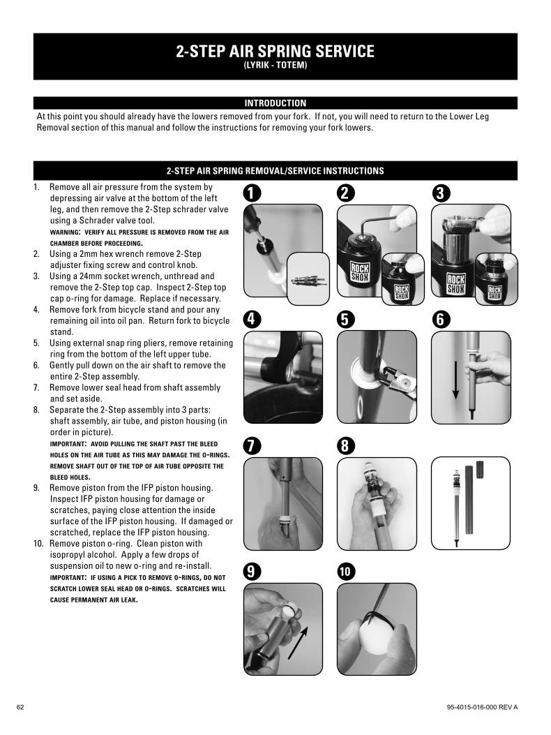
2-step air spring service(lyrik - totem)
introductionAt this point you should already have the lowers removed from your fork. If not, you will need to return to the Lower Leg Removal section of this manual and follow the instructions for removing your fork lowers.
2-step air spring removal/service instructions
Remove all air pressure from the system by depressing air valve at the bottom of the left leg, and then remove the 2-Step schrader valve using a Schrader valve tool.warning: verify all pressure is removed from the air chamber before proceeding.Using a 2mm hex wrench remove 2-Step adjuster fixing screw and control knob.Using a 24mm socket wrench, unthread and remove the 2-Step top cap. Inspect 2-Step top cap o-ring for damage. Replace if necessary.Remove fork from bicycle stand and pour any remaining oil into oil pan. Return fork to bicycle stand.Using external snap ring pliers, remove retaining ring from the bottom of the left upper tube.Gently pull down on the air shaft to remove the entire 2-Step assembly.Remove lower seal head from shaft assembly and set aside.Separate the 2-Step assembly into 3 parts: shaft assembly, air tube, and piston housing (in order in picture). important: avoid pulling the shaft past the bleed holes on the air tube as this may damage the o-rings. remove shaft out of the top of air tube opposite the bleed holes.Remove piston from the IFP piston housing. Inspect IFP piston housing for damage or scratches, paying close attention the inside surface of the IFP piston housing. If damaged or scratched, replace the IFP piston housing.Remove piston o-ring. Clean piston with isopropyl alcohol. Apply a few drops of suspension oil to new o-ring and re-install. important: if using a pick to remove o-rings, do not scratch lower seal head or o-rings. scratches will cause permanent air leak.
1.
2.
3.
4.
5.
6.
7.
8.
9.
10.
21
5
3
6
8
4
9 10
7
© SRAM CORPORATION • 2008 ROCKSHOX TECHNICAL MANUAL 63
2-step air spring removal/service instructions (cont)
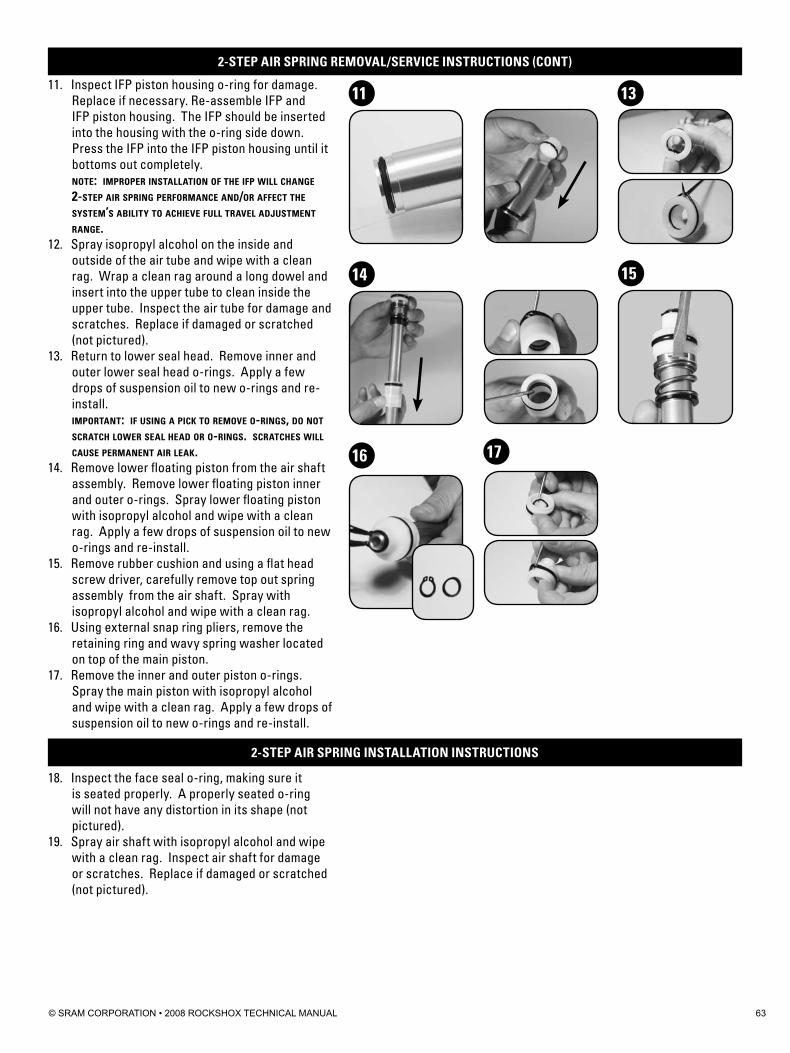
Inspect IFP piston housing o-ring for damage. Replace if necessary. Re-assemble IFP and IFP piston housing. The IFP should be inserted into the housing with the o-ring side down. Press the IFP into the IFP piston housing until it bottoms out completely.note: improper installation of the ifp will change 2-step air spring performance and/or affect the system’s ability to achieve full travel adjustment range.Spray isopropyl alcohol on the inside and outside of the air tube and wipe with a clean rag. Wrap a clean rag around a long dowel and insert into the upper tube to clean inside the upper tube. Inspect the air tube for damage and scratches. Replace if damaged or scratched (not pictured).Return to lower seal head. Remove inner and outer lower seal head o-rings. Apply a few drops of suspension oil to new o-rings and re-install.important: if using a pick to remove o-rings, do not scratch lower seal head or o-rings. scratches will cause permanent air leak.Remove lower floating piston from the air shaft assembly. Remove lower floating piston inner and outer o-rings. Spray lower floating piston with isopropyl alcohol and wipe with a clean rag. Apply a few drops of suspension oil to new o-rings and re-install.Remove rubber cushion and using a flat head screw driver, carefully remove top out spring assembly from the air shaft. Spray with isopropyl alcohol and wipe with a clean rag.Using external snap ring pliers, remove the retaining ring and wavy spring washer located on top of the main piston.Remove the inner and outer piston o-rings. Spray the main piston with isopropyl alcohol and wipe with a clean rag. Apply a few drops of suspension oil to new o-rings and re-install.
11.
12.
13.
14.
15.
16.
17.
2-step air spring installation instructions
Inspect the face seal o-ring, making sure it is seated properly. A properly seated o-ring will not have any distortion in its shape (not pictured).Spray air shaft with isopropyl alcohol and wipe with a clean rag. Inspect air shaft for damage or scratches. Replace if damaged or scratched (not pictured).
18.
19.
13
14 15
16 17
11
95-4015-016-000 REV A64
2-step air spring installation instructions (cont)
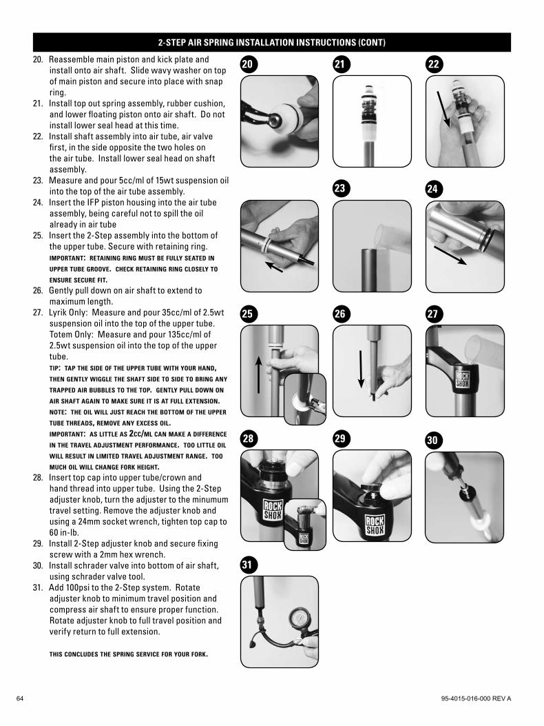
Reassemble main piston and kick plate and install onto air shaft. Slide wavy washer on top of main piston and secure into place with snap ring.Install top out spring assembly, rubber cushion, and lower floating piston onto air shaft. Do not install lower seal head at this time.Install shaft assembly into air tube, air valve first, in the side opposite the two holes on the air tube. Install lower seal head on shaft assembly.Measure and pour 5cc/ml of 15wt suspension oil into the top of the air tube assembly. Insert the IFP piston housing into the air tube assembly, being careful not to spill the oil already in air tubeInsert the 2-Step assembly into the bottom of the upper tube. Secure with retaining ring.important: retaining ring must be fully seated in upper tube groove. check retaining ring closely to ensure secure fit.Gently pull down on air shaft to extend to maximum length.Lyrik Only: Measure and pour 35cc/ml of 2.5wt suspension oil into the top of the upper tube.Totem Only: Measure and pour 135cc/ml of 2.5wt suspension oil into the top of the upper tube.tip: tap the side of the upper tube with your hand, then gently wiggle the shaft side to side to bring any trapped air bubbles to the top. gently pull down on air shaft again to make sure it is at full extension.note: the oil will just reach the bottom of the upper tube threads, remove any excess oil. important: as little as 2cc/ml can make a difference in the travel adjustment performance. too little oil will result in limited travel adjustment range. too much oil will change fork height.Insert top cap into upper tube/crown and hand thread into upper tube. Using the 2-Step adjuster knob, turn the adjuster to the minumum travel setting. Remove the adjuster knob and using a 24mm socket wrench, tighten top cap to 60 in-lb.Install 2-Step adjuster knob and secure fixing screw with a 2mm hex wrench.Install schrader valve into bottom of air shaft, using schrader valve tool.Add 100psi to the 2-Step system. Rotate adjuster knob to minimum travel position and compress air shaft to ensure proper function. Rotate adjuster knob to full travel position and verify return to full extension.
this concludes the spring service for your fork.
20.
21.
22.
23.
24.
25.
26.
27.
28.
29.
30.
31.
22
28
25 26 27
2423
29
2120
31
30