Embed Size (px)
Citation preview
CAUTION
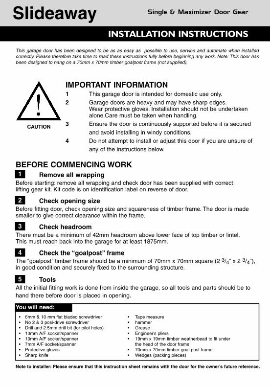
This garage door has been designed to be as as easy as possible to use, service and automate when installedcorrectly. Please therefore take time to read these instructions fully before beginning any work. Note: This door hasbeen designed to hang on a 70mm x 70mm timber goalpost frame (not supplied).
IMPORTANT INFORMATION1 This garage door is intended for domestic use only.
2 Garage doors are heavy and may have sharp edges.Wear protective gloves. Installation should not be undertaken alone.Care must be taken when handling.
3 Ensure the door is continuously supported before it is secured
and avoid installing in windy conditions.
4 Do not attempt to install or adjust this door if you are unsure of
any of the instructions below.
BEFORE COMMENCING WORKRemove all wrapping
Before starting: remove all wrapping and check door has been supplied with correct lifting gear kit. Kit code is on identification label on reverse of door.
Check opening sizeBefore fitting door, check opening size and squareness of timber frame. The door is madesmaller to give correct clearance within the frame.
Check headroomThere must be a minimum of 42mm headroom above lower face of top timber or lintel.This must reach back into the garage for at least 1875mm.
Check the “goalpost” frameThe “goalpost” timber frame should be a minimum of 70mm x 70mm square (2 3/4” x 2 3/4”),in good condition and securely fixed to the surrounding structure.
ToolsAll the initial fitting work is done from inside the garage, so all tools and parts should be tohand there before door is placed in opening.
1
2
3
4
5
You will need:
• 6mm & 10 mm flat bladed screwdriver • Tape measure• No 2 & 3 posi-drive screwdriver • hammer• Drill and 2.5mm drill bit (for pilot holes) • Grease• 13mm A/F socket/spanner • Engineer’s pliers• 10mm A/F socket/spanner • 19mm x 19mm timber weatherbead to fit under • 7mm A/F socket/spanner the head of the door frame• Protective gloves • 70mm x 70mm timber goal post frame• Sharp knife • Wedges (packing pieces)
Note to installer: Please ensure that this instruction sheet remains with the door for the owner’s future reference.ISSUE B MAY 2005 DPIN 045112
• DOOR IS HEAVY TO OPEN:Cause: Spring tension set too lowSolution: Re-set spring tension as detailed on the door maintenance label.
• DOOR OPENS TOO QUICKLY:Causes: Spring tension set too high.Solution: Re-set spring tension as detailed on the door maintenance label.
• DOOR DOES NOT DELATCH:Cause: Latch cables may have been set too long.Solution: If you are not locked out of the garage at the time, then the cables should be set to allow nominal6mm latch engagement with the latch plates. If you are locked out of the garage, call your installer/supplierfor assistance.
• DOOR HANDLE FAILS TO TURN:Probable Cause: A jammed lock barrel.Solution: Unfortunately this can only be remedied by a service call, however, this is not usually chargeableduring the warranty period. Please contact your supplier for details.
• KEY FAILS TO TURN IN LOCK:Probable Cause: Door handle has not been turned to the fully closed position.Solution: Return the handle to the fully closed (horizontal) position and try again. If the problem still persists,contact your supplier.
• LOST KEYS:Solution: Contact your supplier. The lock barrel will need to be replaced, but the method for doing this willvary. If you can get into your garage, the problem can be easily solved by removing the handle assemblyfrom the door and replacing the lock barrel with a new one. If you are locked out, contact your supplier.
THESE INSTRUCTIONS MUST BE FOLLOWED CAREFULLY
GARAGE DOORS ARE HEAVY AND AWKWARD TO HANDLE. ENSUREASSISTANCE IS AVAILABLE AND THAT SAFETY GLOVES ARE WORN.
1. Fix all latches in the fully retracted position.
2. Open door and safely prop in the open position.
3. Remove springs from their hangers. (wear eye protection).
4. With assistance remove prop and close door slowly until fully closed.
5. Prop door in fully closed position and place packers beneath the door between base of door and floor.
6. Remove all track supports and remove track fixing screws from the frame and remove.
7. Remove fixings to main pivot brackets, door should now rest on packers.
8. Remove bottom door mounting brackets.
9. Remove main pivot blocks.
10. The door can now be carefully removed from the opening. Seek assistance in lifting.
11. If door is to be disposed of please do so in a responsible manner in line with the latest legislation applicable at the time.
Slideaway Double & Heavy Double Door Gear
INSTALLATION INSTRUCTIONS 11
Slideaway Single & Maximizer Door Gear
TROUBLE SHOOTING
POWER OPERATION
UPON COMPLETION2Fix lower side seals into position using five 1” clout nailsper side.
Check door operation to ensure door opens and closessatisfactorily.
Check that lock and latches operate correctly.
Ensure all fixings are securely tightened
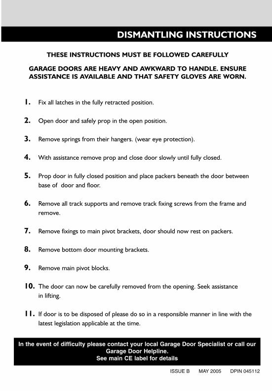
Fit 19mm × 19mm timber weatherbead to the underside ofthe top timber lintel (Fig K).
Do not paint the spring or any moving parts.
Lubricate all moving parts/pivot points (refer tomaintenance label for details) lubrication is an essentialongoing requirement to ensure the continuing smoothoperation of your door.
Ask your professional Garage Door Specialist aboutremote controlled electric operators.
Lintel
Door
19mm × 19mmWeatherbead
1
2
3
4
5
6
7
8
K
DISMANTLING INSTRUCTIONS
In the event of difficulty please contact your local Garage Door Specialist or call ourGarage Door Helpline.
See main CE label for detailsThis door is suitable for power operation. In order to conform with current legislationonly independantly tested and certified operators may be fitted. A list of approved operators is contained on the Declaration of Incorporation supplied with your door.
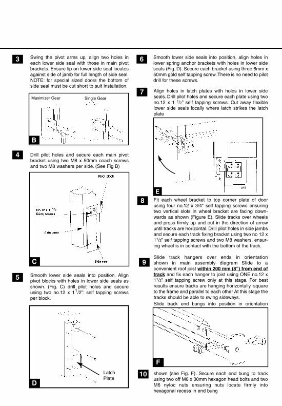
Align holes in latch plates with holes in lower sideseals. Drill pilot holes and secure each plate using twono.12 x 1 1/2” self tapping screws. Cut away flexiblelower side seals locally where latch strikes the latchplate
Fit each wheel bracket to top corner plate of doorusing four no.12 x 3/4" self tapping screws ensuringtwo vertical slots in wheel bracket are facing down-wards as shown (Figure E). Slide tracks over wheelsand press firmly up and out in the direction of arrowuntil tracks are horizontal. Drill pilot holes in side jambsand secure each track fixing bracket using two no 12 x11/2” self tapping screws and two M8 washers, ensur-ing wheel is in contact with the bottom of the track.
Slide track hangers over ends in orientationshown in main assembly diagram Slide to aconvenient roof joist within 200 mm (8”) from end oftrack and fix each hanger to joist using ONE no.12 x11/2” self tapping screw only at this stage. For bestresults ensure tracks are hanging horizontally, squareto the frame and parallel to each other At this stage thetracks should be able to swing sideways.Slide track end bungs into position in orientation
shown (see Fig. F). Secure each end bung to trackusing two off M6 x 30mm hexagon head bolts and twoM6 nyloc nuts ensuring nuts locate firmly intohexagonal recess in end bung
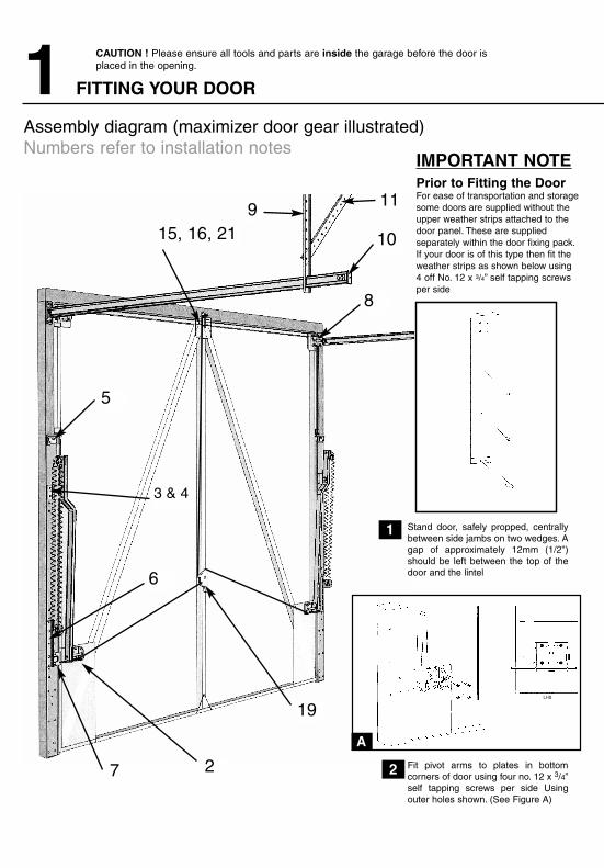
1 FITTING YOUR DOOR
CAUTION ! Please ensure all tools and parts are inside the garage before the door is placed in the opening.
Assembly diagram (maximizer door gear illustrated)Numbers refer to installation notes
Swing the pivot arms up, align two holes ineach lower side seal with those in main pivotbrackets. Ensure lip on lower side seal locatesagainst side of jamb for full length of side seal.NOTE: for special sized doors the bottom ofside seal must be cut short to suit installation.
Drill pilot holes and secure each main pivotbracket using two M8 x 50mm coach screwsand two M8 washers per side. (See Fig B)
Smooth lower side seals into position. Alignpivot blocks with holes in lower side seals asshown. (Fig. C) drill pilot holes and secureusing two no.12 x 11/2”: self tapping screwsper block.
1
2
3
4
5
6 11
16
12
Fully open door and prop securely in position.With the door still open the tracks should be parallelThis can be checked by ensuring both roller wheels arein contact with the track end bungs. Bolt track braces tohangers using one M6 x 20mm hexagon head screwand one M6 nyloc nut per side Fix each track brace tojoist using one no.12 x 11/2” self tapping screw.
Lock each track hanger in position by fixing to joistusing a second no.12 x 11/2” self tapping screw.
Smooth lower side seals into position, align holes inlower spring anchor brackets with holes in lower sideseals (Fig. D). Secure each bracket using three 6mm x50mm gold self tapping screw.There is no need to pilotdrill for these screws.
A
C
F
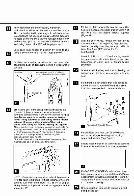
With the door closed, remove the park pin torelease the latch pin (Figure H) Align the catchbracket centrally over the latch pin with thelower face 3mm (1/8”) above the topdoor bracket.
Insert 2 off No 12 x 1 1/2” self tapping screwsthrough screws slots into head timber, useadjustment on screw slots to ensure correctalignment
Open the door half way and fit lock following theinstructions in the lock pack supplied with yourdoor.
LHS
IMPORTANT NOTEPrior to Fitting the DoorFor ease of transportation and storagesome doors are supplied without theupper weather strips attached to thedoor panel. These are suppliedseparately within the door fixing pack.If your door is of this type then fit theweather strips as shown below using4 off No. 12 x 3/4” self tapping screwsper side
Stand door, safely propped, centrallybetween side jambs on two wedges. Agap of approximately 12mm (1/2”)should be left between the top of thedoor and the lintel
Fit pivot arms to plates in bottomcorners of door using four no. 12 x 3/4”self tapping screws per side Usingouter holes shown. (See Figure A)
B
Maximizer Gear
D
LatchPlate
7
8
9
10
ELHS
Establish gear setting positions for door from labelattached to back of door. Note setting 1 is top anchorposition
Still with the door in the open position and wearing eyeprotection fit lower spring anchors as shown and fitsprings to spring anchors in orientation shown (See fig G).Note Spring loops to be located on anchor brackethooks facing outwards so that spring body is locatedin board of spring anchor brackets. When usingcentre hook spring will require twisting 180 degrees.Always use the same number of springs on each side. For2 springs use outer hooks, for 1 spring use centre hook,for 3 springs use all hooks. A minimum of 2 through tomaximum of 3 springs per side may be supplieddepending upon door weight.Check door operation and re-tension if necessary. (Seemaintenance label on side seals for details).
NOTE – Some doors are supplied without the provisionfor a top latch to be fitted. In these instances the com-ponents outlined in instructions 15 & 16 will be surplusto requirements. If your door is of this type proceed toinstruction 17.
13
14
15
17
H
G
18
19
20
21
22
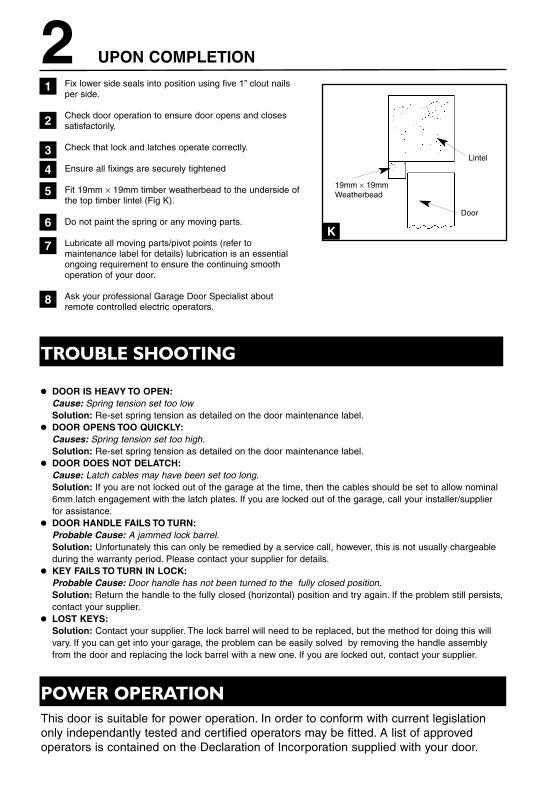
From front of door ensure that lock handle isturned fully anti-clockwise From inside slidelock cam onto spindle in orientation shown
Fit lock lever onto lock cam as shown andsecure to lock spindle using self tappingscrew and washer. (See Figure I)
Locate looped ends of all latch cables securelyin lever slots and adjust for correct operation
ENGAGEMENT NOTE On adjustment of toplatch, please ensure a nominal 6mm (1/4”) pinengagement through catch bracket (Figure J).Adjustment of other latches should also be set to 6 mm latch overlap.
Check operation from inside garage to avoidbeing locked out
I
J
Typical Lock Assembly Shown.
18
19
19
20
915, 16, 21
11
10
8
5
6
19
27
3 & 4
Single Gear
Position 1
Position 6
Fit the top latch assembly into the pre-drilledholes on the top centre door bracket using 4 offNo. 10 x 1/2” self-tapping screws supplied(Figure H).
Note: lower spring anchor is not handed.(i.e. same bracket used on left and right)
Align holes in latch plates with holes in lower sideseals. Drill pilot holes and secure each plate using twono.12 x 1 1/2” self tapping screws. Cut away flexiblelower side seals locally where latch strikes the latchplate
Fit each wheel bracket to top corner plate of doorusing four no.12 x 3/4" self tapping screws ensuringtwo vertical slots in wheel bracket are facing down-wards as shown (Figure E). Slide tracks over wheelsand press firmly up and out in the direction of arrowuntil tracks are horizontal. Drill pilot holes in side jambsand secure each track fixing bracket using two no 12 x11/2” self tapping screws and two M8 washers, ensur-ing wheel is in contact with the bottom of the track.
Slide track hangers over ends in orientationshown in main assembly diagram Slide to aconvenient roof joist within 200 mm (8”) from end oftrack and fix each hanger to joist using ONE no.12 x11/2” self tapping screw only at this stage. For bestresults ensure tracks are hanging horizontally, squareto the frame and parallel to each other At this stage thetracks should be able to swing sideways.Slide track end bungs into position in orientation
shown (see Fig. F). Secure each end bung to trackusing two off M6 x 30mm hexagon head bolts and twoM6 nyloc nuts ensuring nuts locate firmly intohexagonal recess in end bung
1 FITTING YOUR DOOR
CAUTION ! Please ensure all tools and parts are inside the garage before the door is placed in the opening.
Assembly diagram (maximizer door gear illustrated)Numbers refer to installation notes
Swing the pivot arms up, align two holes ineach lower side seal with those in main pivotbrackets. Ensure lip on lower side seal locatesagainst side of jamb for full length of side seal.NOTE: for special sized doors the bottom ofside seal must be cut short to suit installation.
Drill pilot holes and secure each main pivotbracket using two M8 x 50mm coach screwsand two M8 washers per side. (See Fig B)
Smooth lower side seals into position. Alignpivot blocks with holes in lower side seals asshown. (Fig. C) drill pilot holes and secureusing two no.12 x 11/2”: self tapping screwsper block.
1
2
3
4
5
6 11
16
12
Fully open door and prop securely in position.With the door still open the tracks should be parallelThis can be checked by ensuring both roller wheels arein contact with the track end bungs. Bolt track braces tohangers using one M6 x 20mm hexagon head screwand one M6 nyloc nut per side Fix each track brace tojoist using one no.12 x 11/2” self tapping screw.
Lock each track hanger in position by fixing to joistusing a second no.12 x 11/2” self tapping screw.
Smooth lower side seals into position, align holes inlower spring anchor brackets with holes in lower sideseals (Fig. D). Secure each bracket using three 6mm x50mm gold self tapping screw.There is no need to pilotdrill for these screws.
A
C
F
With the door closed, remove the park pin torelease the latch pin (Figure H) Align the catchbracket centrally over the latch pin with thelower face 3mm (1/8”) above the topdoor bracket.
Insert 2 off No 12 x 1 1/2” self tapping screwsthrough screws slots into head timber, useadjustment on screw slots to ensure correctalignment
Open the door half way and fit lock following theinstructions in the lock pack supplied with yourdoor.
LHS
IMPORTANT NOTEPrior to Fitting the DoorFor ease of transportation and storagesome doors are supplied without theupper weather strips attached to thedoor panel. These are suppliedseparately within the door fixing pack.If your door is of this type then fit theweather strips as shown below using4 off No. 12 x 3/4” self tapping screwsper side
Stand door, safely propped, centrallybetween side jambs on two wedges. Agap of approximately 12mm (1/2”)should be left between the top of thedoor and the lintel
Fit pivot arms to plates in bottomcorners of door using four no. 12 x 3/4”self tapping screws per side Usingouter holes shown. (See Figure A)
B
Maximizer Gear
D
LatchPlate
7
8
9
10
ELHS
Establish gear setting positions for door from labelattached to back of door. Note setting 1 is top anchorposition
Still with the door in the open position and wearing eyeprotection fit lower spring anchors as shown and fitsprings to spring anchors in orientation shown (See fig G).Note Spring loops to be located on anchor brackethooks facing outwards so that spring body is locatedin board of spring anchor brackets. When usingcentre hook spring will require twisting 180 degrees.Always use the same number of springs on each side. For2 springs use outer hooks, for 1 spring use centre hook,for 3 springs use all hooks. A minimum of 2 through tomaximum of 3 springs per side may be supplieddepending upon door weight.Check door operation and re-tension if necessary. (Seemaintenance label on side seals for details).
NOTE – Some doors are supplied without the provisionfor a top latch to be fitted. In these instances the com-ponents outlined in instructions 15 & 16 will be surplusto requirements. If your door is of this type proceed toinstruction 17.
13
14
15
17
H
G
18
19
20
21
22
From front of door ensure that lock handle isturned fully anti-clockwise From inside slidelock cam onto spindle in orientation shown
Fit lock lever onto lock cam as shown andsecure to lock spindle using self tappingscrew and washer. (See Figure I)
Locate looped ends of all latch cables securelyin lever slots and adjust for correct operation
ENGAGEMENT NOTE On adjustment of toplatch, please ensure a nominal 6mm (1/4”) pinengagement through catch bracket (Figure J).Adjustment of other latches should also be set to 6 mm latch overlap.
Check operation from inside garage to avoidbeing locked out
I
J
Typical Lock Assembly Shown.
18
19
19
20
915, 16, 21
11
10
8
5
6
19
27
3 & 4
Single Gear
Position 1
Position 6
Fit the top latch assembly into the pre-drilledholes on the top centre door bracket using 4 offNo. 10 x 1/2” self-tapping screws supplied(Figure H).
Note: lower spring anchor is not handed.(i.e. same bracket used on left and right)
CAUTION
This garage door has been designed to be as as easy as possible to use, service and automate when installedcorrectly. Please therefore take time to read these instructions fully before beginning any work. Note: This door hasbeen designed to hang on a 70mm x 70mm timber goalpost frame (not supplied).
IMPORTANT INFORMATION1 This garage door is intended for domestic use only.
2 Garage doors are heavy and may have sharp edges.Wear protective gloves. Installation should not be undertaken alone.Care must be taken when handling.
3 Ensure the door is continuously supported before it is secured
and avoid installing in windy conditions.
4 Do not attempt to install or adjust this door if you are unsure of
any of the instructions below.
BEFORE COMMENCING WORKRemove all wrapping
Before starting: remove all wrapping and check door has been supplied with correct lifting gear kit. Kit code is on identification label on reverse of door.
Check opening sizeBefore fitting door, check opening size and squareness of timber frame. The door is madesmaller to give correct clearance within the frame.
Check headroomThere must be a minimum of 42mm headroom above lower face of top timber or lintel.This must reach back into the garage for at least 1875mm.
Check the “goalpost” frameThe “goalpost” timber frame should be a minimum of 70mm x 70mm square (2 3/4” x 2 3/4”),in good condition and securely fixed to the surrounding structure.
ToolsAll the initial fitting work is done from inside the garage, so all tools and parts should be tohand there before door is placed in opening.
1
2
3
4
5
You will need:
• 6mm & 10 mm flat bladed screwdriver • Tape measure• No 2 & 3 posi-drive screwdriver • hammer• Drill and 2.5mm drill bit (for pilot holes) • Grease• 13mm A/F socket/spanner • Engineer’s pliers• 10mm A/F socket/spanner • 19mm x 19mm timber weatherbead to fit under • 7mm A/F socket/spanner the head of the door frame• Protective gloves • 70mm x 70mm timber goal post frame• Sharp knife • Wedges (packing pieces)
Note to installer: Please ensure that this instruction sheet remains with the door for the owner’s future reference.ISSUE B MAY 2005 DPIN 045112
• DOOR IS HEAVY TO OPEN:Cause: Spring tension set too lowSolution: Re-set spring tension as detailed on the door maintenance label.
• DOOR OPENS TOO QUICKLY:Causes: Spring tension set too high.Solution: Re-set spring tension as detailed on the door maintenance label.
• DOOR DOES NOT DELATCH:Cause: Latch cables may have been set too long.Solution: If you are not locked out of the garage at the time, then the cables should be set to allow nominal6mm latch engagement with the latch plates. If you are locked out of the garage, call your installer/supplierfor assistance.
• DOOR HANDLE FAILS TO TURN:Probable Cause: A jammed lock barrel.Solution: Unfortunately this can only be remedied by a service call, however, this is not usually chargeableduring the warranty period. Please contact your supplier for details.
• KEY FAILS TO TURN IN LOCK:Probable Cause: Door handle has not been turned to the fully closed position.Solution: Return the handle to the fully closed (horizontal) position and try again. If the problem still persists,contact your supplier.
• LOST KEYS:Solution: Contact your supplier. The lock barrel will need to be replaced, but the method for doing this willvary. If you can get into your garage, the problem can be easily solved by removing the handle assemblyfrom the door and replacing the lock barrel with a new one. If you are locked out, contact your supplier.
THESE INSTRUCTIONS MUST BE FOLLOWED CAREFULLY
GARAGE DOORS ARE HEAVY AND AWKWARD TO HANDLE. ENSUREASSISTANCE IS AVAILABLE AND THAT SAFETY GLOVES ARE WORN.
1. Fix all latches in the fully retracted position.
2. Open door and safely prop in the open position.
3. Remove springs from their hangers. (wear eye protection).
4. With assistance remove prop and close door slowly until fully closed.
5. Prop door in fully closed position and place packers beneath the door between base of door and floor.
6. Remove all track supports and remove track fixing screws from the frame and remove.
7. Remove fixings to main pivot brackets, door should now rest on packers.
8. Remove bottom door mounting brackets.
9. Remove main pivot blocks.
10. The door can now be carefully removed from the opening. Seek assistance in lifting.
11. If door is to be disposed of please do so in a responsible manner in line with the latest legislation applicable at the time.
Slideaway Double & Heavy Double Door Gear
INSTALLATION INSTRUCTIONS 11
Slideaway Single & Maximizer Door Gear
TROUBLE SHOOTING
POWER OPERATION
UPON COMPLETION2Fix lower side seals into position using five 1” clout nailsper side.
Check door operation to ensure door opens and closessatisfactorily.
Check that lock and latches operate correctly.
Ensure all fixings are securely tightened
Fit 19mm × 19mm timber weatherbead to the underside ofthe top timber lintel (Fig K).
Do not paint the spring or any moving parts.
Lubricate all moving parts/pivot points (refer tomaintenance label for details) lubrication is an essentialongoing requirement to ensure the continuing smoothoperation of your door.
Ask your professional Garage Door Specialist aboutremote controlled electric operators.
Lintel
Door
19mm × 19mmWeatherbead
1
2
3
4
5
6
7
8
K
DISMANTLING INSTRUCTIONS
In the event of difficulty please contact your local Garage Door Specialist or call ourGarage Door Helpline.
See main CE label for detailsThis door is suitable for power operation. In order to conform with current legislationonly independantly tested and certified operators may be fitted. A list of approved operators is contained on the Declaration of Incorporation supplied with your door.