Embed Size (px)
Citation preview
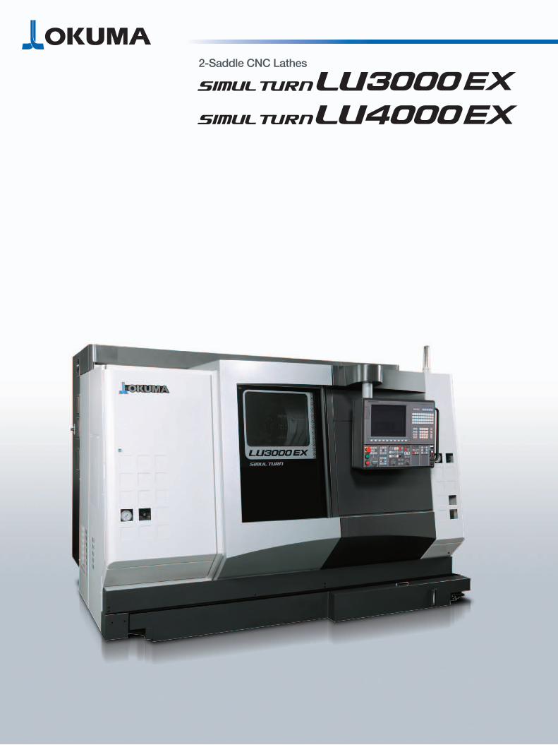
2-Saddle CNC Lathes

1 2
2-Saddle CNC Lathes
(MY speci�cations)
Thermo-FriendlyConcept
Collision AvoidanceSystem
MachiningNavi
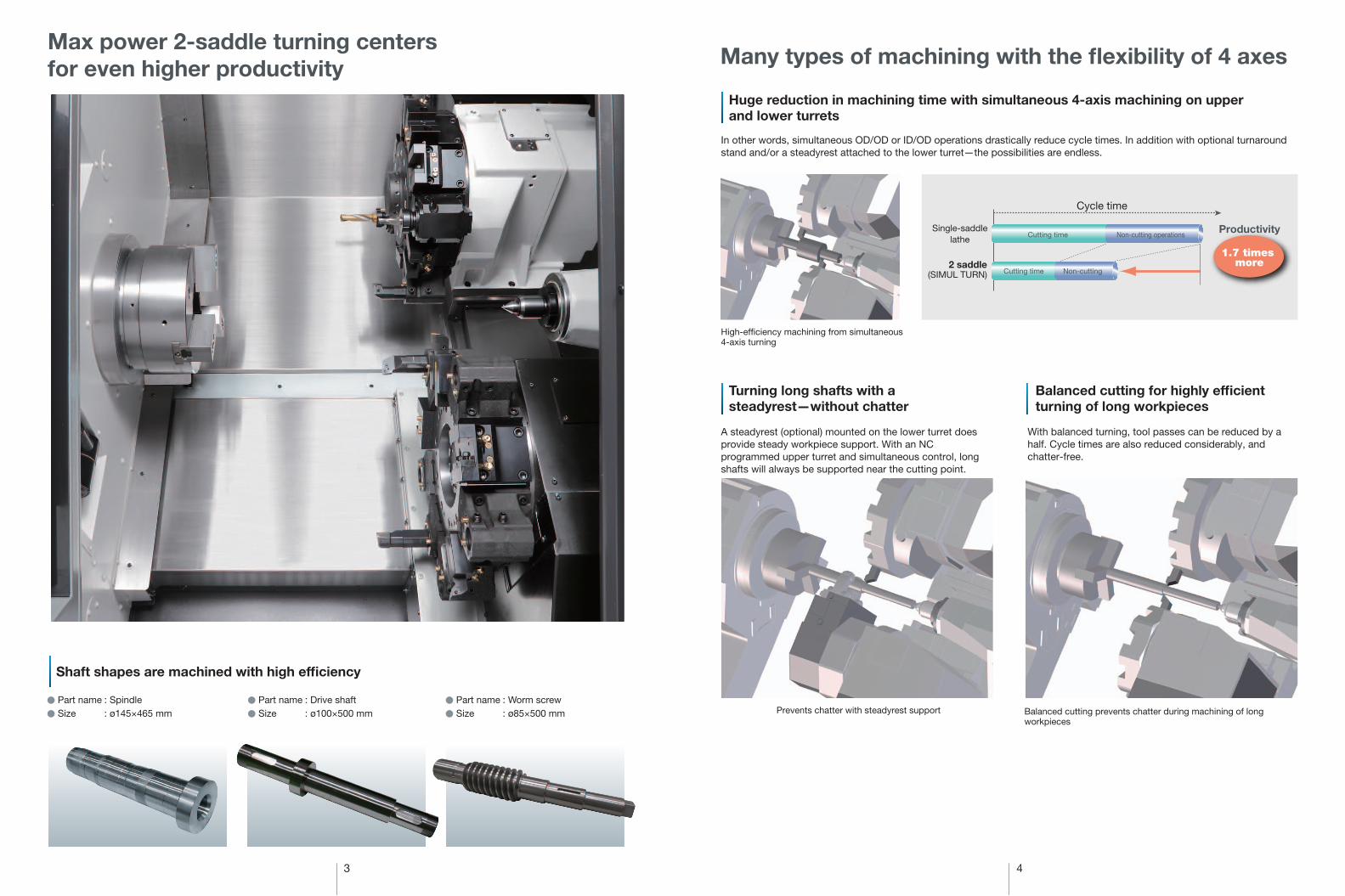
Max power 2-saddle turning centersfor even higher productivity
Huge productivity gains at higher performance levels
Achieve the best production system with our wide-ranging lineup
Wide array of intelligent technologies are powerful support for operator
Photos include optional speci�cations.
3 4
Max power 2-saddle turning centersfor even higher productivity Many types of machining with the flexibility of 4 axes
Single-saddlelathe
Cutting time
Cutting time Non-cutting
Non-cutting operationsProductivity
1.7 times more2 saddle
(SIMUL TURN)
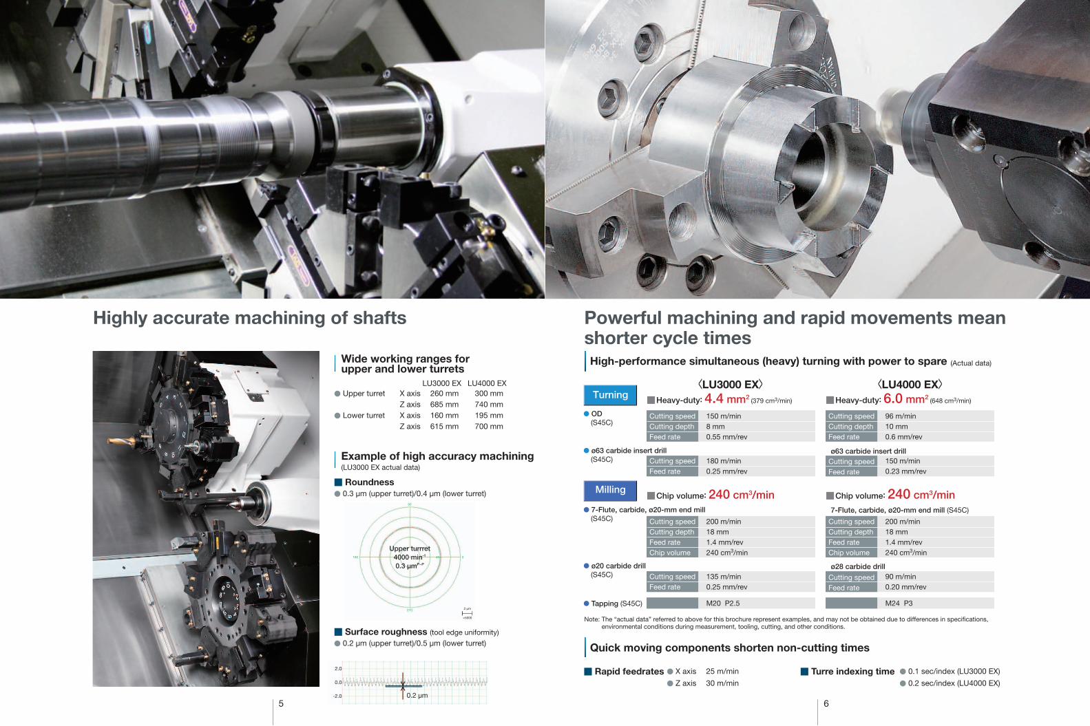
A steadyrest (optional) mounted on the lower turret does provide steady workpiece support. With an NC programmed upper turret and simultaneous control, long shafts will always be supported near the cutting point.
In other words, simultaneous OD/OD or ID/OD operations drastically reduce cycle times. In addition with optional turnaround stand and/or a steadyrest attached to the lower turret—the possibilities are endless.
High-ef�ciency machining from simultaneous 4-axis turning
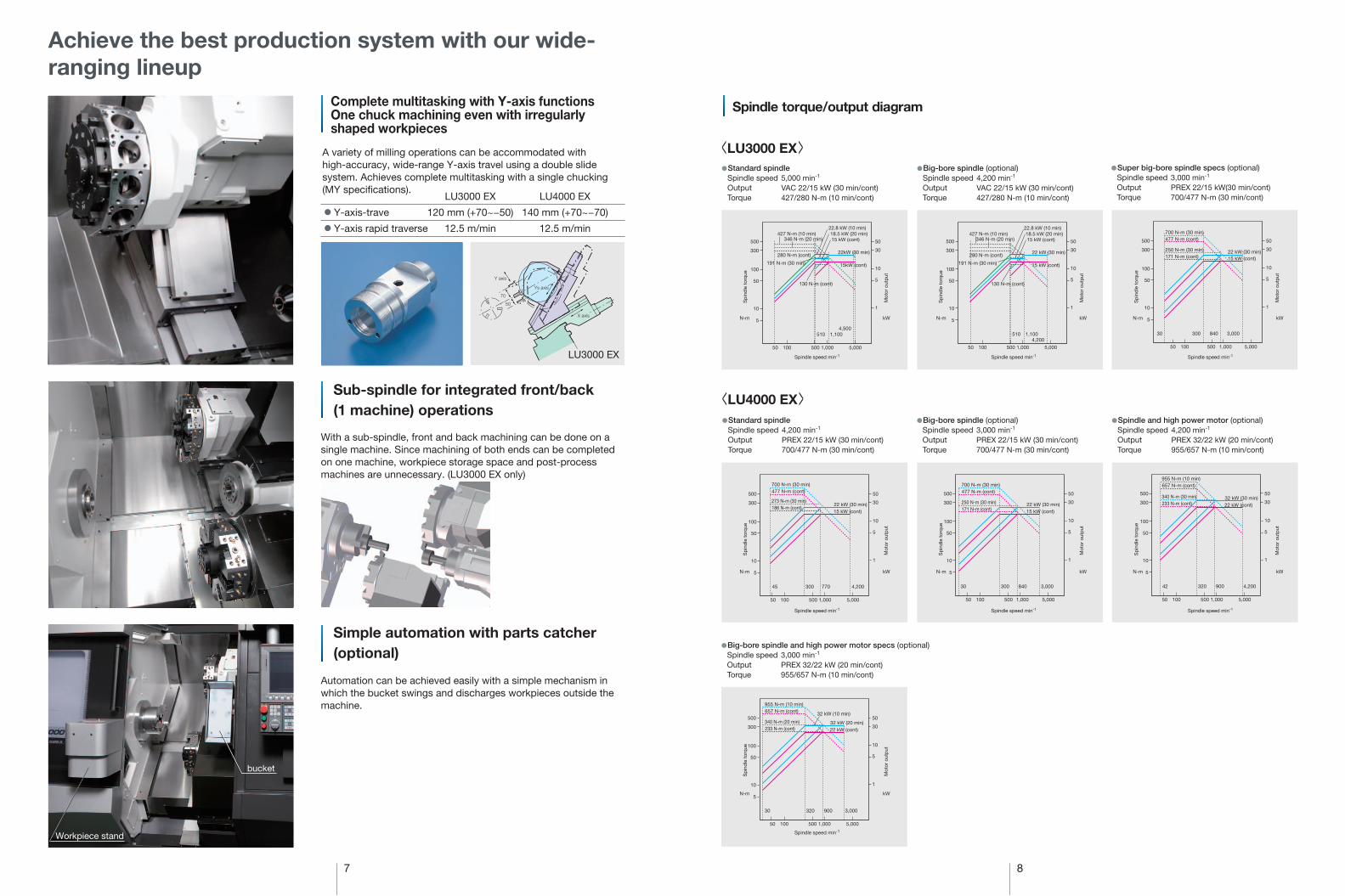
Balanced cutting prevents chatter during machining of long workpieces
With balanced turning, tool passes can be reduced by a half. Cycle times are also reduced considerably, and chatter-free.
Balanced cutting for highly efficient turning of long workpieces
Turning long shafts with a steadyrest—without chatter
Huge reduction in machining time with simultaneous 4-axis machining on upperand lower turrets
Shaft shapes are machined with high efficiency
● Part name : Spindle
● Size : ø145×465 mm● Part name : Drive shaft
● Size : ø100×500 mm● Part name : Worm screw
● Size : ø85×500 mm Prevents chatter with steadyrest support
Cycle time
5 6
Turning■Heavy-duty: 4.4 mm2 (379 cm3/min)
● OD(S45C)
● ø63 carbide insert drill(S45C)
■Chip volume: 240 cm3/min● 7-Flute, carbide, ø20-mm end mill
(S45C)
Milling
● ø20 carbide drill(S45C)
● Tapping (S45C)
■Heavy-duty: 6.0 mm2 (648 cm3/min)
■Chip volume: 240 cm3/min
ø63 carbide insert drill
ø28 carbide drill
7-Flute, carbide, ø20-mm end mill (S45C)
<LU3000 EX> <LU4000 EX>Cutting speedCutting depthFeed rate
150 m/min8 mm0.55 mm/rev
Cutting speedFeed rate
180 m/min0.25 mm/rev
Cutting speedCutting depthFeed rateChip volume
200 m/min18 mm1.4 mm/rev240 cm3/min
Cutting speedFeed rate
135 m/min0.25 mm/rev
Cutting speedCutting depthFeed rate
96 m/min10 mm0.6 mm/rev
Cutting speedFeed rate
150 m/min0.23 mm/rev
Cutting speedCutting depthFeed rateChip volume
200 m/min18 mm1.4 mm/rev240 cm3/min
Cutting speedFeed rate
90 m/min0.20 mm/rev
M24 P3M20 P2.5
Highly accurate machining of shafts Powerful machining and rapid movements mean shorter cycle times
Example of high accuracy machining(LU3000 EX actual data)
■ Roundness● 0.3 μm (upper turret)/0.4 μm (lower turret)
■ Surface roughness (tool edge uniformity)
● 0.2 μm (upper turret)/0.5 μm (lower turret)
Wide working ranges forupper and lower turrets
● Upper turret X axis 260 mm 300 mm Z axis 685 mm 740 mm
● Lower turret X axis 160 mm 195 mm Z axis 615 mm 700 mm
Upper turrret4000 min-1
0.3 µmP−P
0.2 µm
2.0
0.0
-2.0
90
270
180 045
2 µm
×5000
LU3000 EX LU4000 EX
High-performance simultaneous (heavy) turning with power to spare
Quick moving components shorten non-cutting times
(Actual data)
Note: The “actual data” referred to above for this brochure represent examples, and may not be obtained due to differences in speci�cations, environmental conditions during measurement, tooling, cutting, and other conditions.
■ Rapid feedrates ● X axis 25 m/min
● Z axis 30 m/min■ Turre indexing time ● 0.1 sec/index (LU3000 EX)
● 0.2 sec/index (LU4000 EX)
With a sub-spindle, front and back machining can be done on a single machine. Since machining of both ends can be completed on one machine, workpiece storage space and post-process machines are unnecessary. (LU3000 EX only)
Automation can be achieved easily with a simple mechanism in which the bucket swings and discharges workpieces outside the machine.
● Y-axis-trave
● Y-axis rapid traverse
LU3000 EX
120 mm (+70~−50)
12.5 m/min
LU4000 EX
140 mm (+70~−70)
12.5 m/min
7 8
<LU3000 EX>●Standard spindle
Spindle speed 5,000 min-1
Output VAC 22/15 kW (30 min/cont)Torque 427/280 N-m (10 min/cont)
●Super big-bore spindle specs (optional)Spindle speed 3,000 min-1
Output PREX 22/15 kW(30 min/cont)Torque 700/477 N-m (30 min/cont)
●Big-bore spindle (optional)Spindle speed 4,200 min-1
Output VAC 22/15 kW (30 min/cont)Torque 427/280 N-m (10 min/cont)
<LU4000 EX>●Standard spindle
Spindle speed 4,200 min-1
Output PREX 22/15 kW (30 min/cont)Torque 700/477 N-m (30 min/cont)
●Spindle and high power motor (optional)Spindle speed 4,200 min-1
Output PREX 32/22 kW (20 min/cont)Torque 955/657 N-m (10 min/cont)
●Big-bore spindle and high power motor specs (optional)Spindle speed 3,000 min-1
Output PREX 32/22 kW (20 min/cont)Torque 955/657 N-m (10 min/cont)
LU3000 EX
Spindle torque/output diagram
N-m kW
500
100
300
50
10
5
1,000 5,000500
Spindle speed min-1
10050
1
5
10
50
30
500
100
300
50
10
5
1,000 5,00050010050
1
5
10
50
30
500
100
300
50
10
5
1,000 5,00050010050
1
5
10
50
30
●Big-bore spindle (optional)Spindle speed 3,000 min-1
Output PREX 22/15 kW (30 min/cont)Torque 700/477 N-m (30 min/cont)
510 1,1004,500
427 N-m (10 min)346 N-m (20 min)
280 N-m (cont)
191 N-m (30 min)
130 N-m (cont)
22.8 kW (10 min)18.5 kW (20 min)
22kW (30 min)
15kW (cont)
15 kW (cont)
510 1,1004,200
427 N-m (10 min)346 N-m (20 min)
280 N-m (cont)
191 N-m (30 min)
130 N-m (cont)
22.8 kW (10 min)18.5 kW (20 min)
22 kW (30 min)
15 kW (cont)
15 kW (cont)700 N-m (30 min)477 N-m (cont)
250 N-m (30 min)171 N-m (cont)
22 kW (30 min)15 kW (cont)
30030 840 3,000
500
100
300
50
10
5
1,000 5,00050010050
1
5
10
50
30
500
100
300
50
10
5
1,000 5,00050010050
1
5
10
50
30
500
100
300
50
10
5
1,000 5,00050010050
1
5
10
50
30
477 N-m (cont)700 N-m (30 min)
186 N-m (cont)273 N-m (30 min)
22 kW (30 min)15 kW (cont)
30045 770 4,200 30030 840 3,000
477 N-m (cont)700 N-m (30 min)
171 N-m (cont)250 N-m (30 min) 22 kW (30 min)
15 kW (cont)
657 N-m (cont)955 N-m (10 min)
233 N-m (cont)340 N-m (30 min) 32 kW (30 min)
22 kW (cont)
500
100
300
50
10
5
1,000 5,00050010050
1
5
10
50
30
32030 900 3,000
32 kW (20 min)22 kW (cont)
657 N-m (cont)955 N-m (10 min)
233 N-m (cont)340 N-m (20 min)
32 kW (10 min)
32042 900 4,200
Achieve the best production system with our wide-ranging lineup
Complete multitasking with Y-axis functionsOne chuck machining even with irregularlyshaped workpieces
A variety of milling operations can be accommodated with high-accuracy, wide-range Y-axis travel using a double slide system. Achieves complete multitasking with a single chucking (MY speci�cations).
Y axis
70
50
X axis
Ys axis
Sub-spindle for integrated front/back(1 machine) operations
Simple automation with parts catcher (optional)
Sp
ind
le t
orq
ue
Mot
or o
utp
ut
Sp
ind
le t
orq
ue
Mot
or o
utp
ut
Sp
ind
le t
orq
ue
Mot
or o
utp
ut
Sp
ind
le t
orq
ue
Mot
or o
utp
ut
Sp
ind
le t
orq
ue
Mot
or o
utp
ut
Sp
ind
le t
orq
ue
Mot
or o
utp
ut
Sp
ind
le t
orq
ue
Mot
or o
utp
ut
N-m kW
Spindle speed min-1
N-m kW
Spindle speed min-1
N-m kW
Spindle speed min-1
N-m kW
Spindle speed min-1
N-m kW
Spindle speed min-1
N-m kW
Spindle speed min-1
bucket
Workpiece stand
9 10
Simple machine construction
Machine designs that equalize ambient temperatures
Okuma’s Thermo-Friendly is a structurally designed system that provides astonishing machining accuracy.It frees the machinist from troublesome offsets and machine warm-ups—is superb for long runs, multitasking, front/backend work, plus Y-axis applications.
Manageable Deformation—Accurately Controlled
Thermo-Friendly Concept
The unique approach of "accepting temperature "changes."
Thermo-FriendlyConcept
Compensation due to ambient temperature changes and temporary midday or evening machine stops is performed fewer times thanks to outstanding dimensional stability. This leads to better machine utilization, improving ef�ciency especially for mass-production machining.
■ Fewer tool compensation checks
■ Box slant bedThe innovative box slant bed gives you far more consistently higher accuracies than conventional lathes.
In environments with normal temperature changes, machining accuracies equivalent to those in temperature-controlled rooms are achieved.As long as the operator is comfortable, no air conditioning is needed to ensure accuracy.
Environmental economic benefits of Okuma’s Thermo-Friendly Concept
■ Amount of energy consumed for temperature-controlled room
Savings of approximately 210,000 kWh per year *
Prevents CO2 emissions equivalent to about 11,500 beech trees
High dimensional stability
Machining restart
Room temp change
Machine start up
Ecology & EconomyMachines and technology to achieve eco-friendly "monozukuri"
Thermo-Friendly Concept
Energy-saving functions Energy-saving technology
■ High-performance single CPU configuration ■ Energy savings from simple design■ Energy-saving display device
Energy-saving servo, NC units ■ Power-saving function
Peripheral device power shutoff after completion of automatic operation
• Spindle cooler, etc.
Energy-saving function
* Calculations are examples only, and may differ from actual circumstances. Temperature-controlled room capacity: 10 x 10 x H3 m ±2°C
Okuma Control OSP-P300L
Satisfaction from complete control of a machine toolAs a “machine & control” builder, Okuma makes further strides in machine tool manufacturing with
this superb Control featuring “Easy Operation.” Okuma took a close look at the way machinists
actually operate machine tools, to help them create smoother and more effective ways of producing
parts. Novice operators as well as professional machinists get complete control—and satisfaction.
Moreover, what you want to see and do conveniently come together in a “single-mode operation.”
First, select one of three operation screens.
Then simply touch the screen or press a function key to see and do your job.
Collision Avoidance System (Optional)
Collision prevention
Machining Navi L-g (Optional)
Cutting condition search for turning
■ World’s first “Collision-Free Machine” ■ Chatter-free applications for lathes
CAS prevents collisions in automatic or manual mode, providing risk-free protection for the machine and great con�dence for the operator.
Chatter in a lathe can be suppressed by changing spindle speeds to the ideal amplitude and wave cycle—without decreasing spindle speed.
■ Setup operations
■ Trial/continuous cuts ■ Programming ■ Tool preparations
Fine tuning zone
Chatter graphed
Virtual machine (collision check)
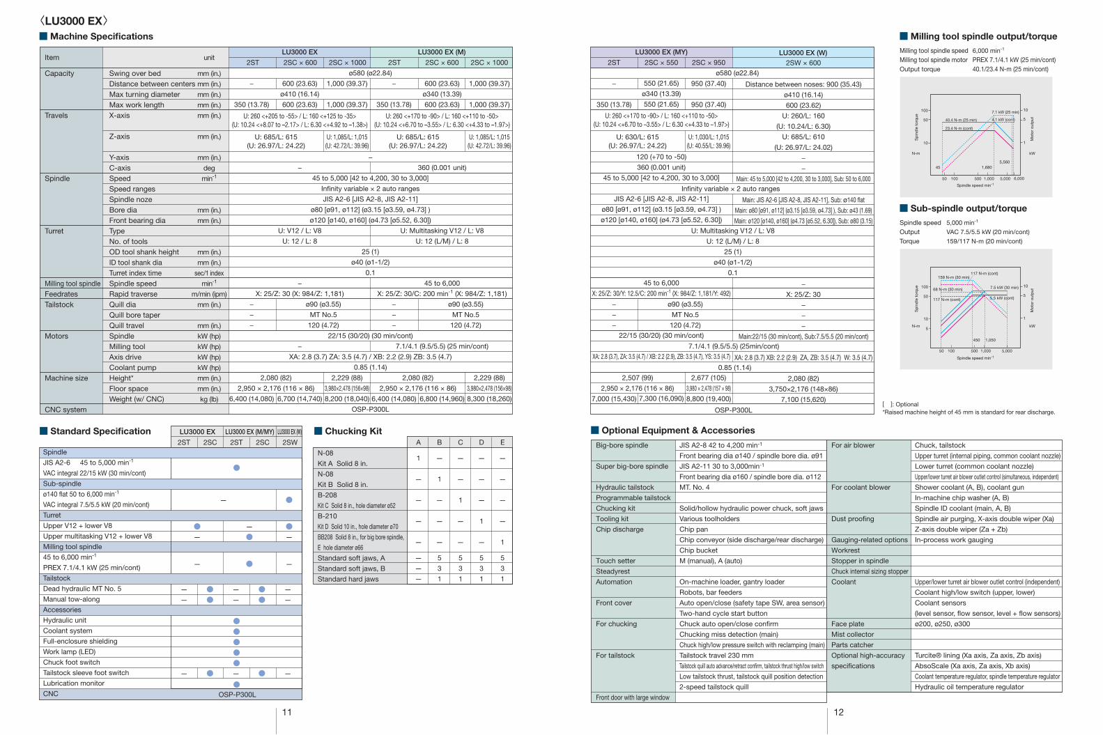
Milling tool spindle speed 6,000 min-1
Milling tool spindle motor PREX 7.1/4.1 kW (25 min/cont)Output torque 40.1/23.4 N-m (25 min/cont)
■ Milling tool spindle output/torque
Spindle speed 5,000 min-1
Output VAC 7.5/5.5 kW (20 min/cont)
Torque 159/117 N-m (20 min/cont)
■ Sub-spindle output/torque
<LU3000 EX>
■ Optional Equipment & Accessories
JIS A2-8 42 to 4,200 min-1
Front bearing dia ø140 / spindle bore dia. ø91
JIS A2-11 30 to 3,000min-1
Front bearing dia ø160 / spindle bore dia. ø112
MT. No. 4
Solid/hollow hydraulic power chuck, soft jaws
Various toolholders
Chip pan
Chip conveyor (side discharge/rear discharge)
Chip bucket
M (manual), A (auto)
On-machine loader, gantry loader
Robots, bar feeders
Auto open/close (safety tape SW, area sensor)
Two-hand cycle start button
Chuck auto open/close con�rm
Chucking miss detection (main)
Chuck high/low pressure switch with reclamping (main)
Tailstock travel 230 mm
Tailstock quill auto advance/retract con�rm, tailstock thrust high/low switch
Low tailstock thrust, tailstock quill position detection
2-speed tailstock quill
Big-bore spindle
Super big-bore spindle
Hydraulic tailstock
Programmable tailstock
Chucking kit
Tooling kit
Chip discharge
Touch setter
Steadyrest
Automation
Front cover
For chucking
For tailstock
Front door with large window
[ ]: Optional*Raised machine height of 45 mm is standard for rear discharge.
Chuck, tailstock
Upper turret (internal piping, common coolant nozzle)
Lower turret (common coolant nozzle)
Upper/lower turret air blower outlet control (simultaneous, independent)
Shower coolant (A, B), coolant gun
In-machine chip washer (A, B)
Spindle ID coolant (main, A, B)
Spindle air purging, X-axis double wiper (Xa)
Z-axis double wiper (Za + Zb)
In-process work gauging
Upper/lower turret air blower outlet control (independent)
Coolant high/low switch (upper, lower)
Coolant sensors
(level sensor, ©ow sensor, level + ©ow sensors)
ø200, ø250, ø300
Turcite® lining (Xa axis, Za axis, Zb axis)
AbsoScale (Xa axis, Za axis, Xb axis)
Coolant temperature regulator, spindle temperature regulator
Hydraulic oil temperature regulator
For air blower
For coolant blower
Dust proo�ng
Gauging-related options
Workrest
Stopper in spindle
Chuck internal sizing stopper
Coolant
Face plate
Mist collector
Parts catcher
Optional high-accuracy
speci�cations
117 N-m (cont)
40.4 N-m (25 min)
23.4 N-m (cont)
7.1 kW (25 min)100
50
10
1,000 5,000 6,00050010050
45 1,6805,560
1
5
10
4.1 kW (cont)
159 N-m (30 min)
7.5 kW (30 min)
5.5 kW (cont)
100
50
10
5
1,000 5,00050010050
1
5
10
450 1,050
68 N-m (30 min)
117 N-m (cont)
■ Machine Specifications
LU3000 EX LU3000 EX (M)
2SC × 6002ST 2STItem
Capacity
Travels
Spindle
Turret
Milling tool spindleFeedratesTailstock
Motors
Machine size
CNC system
Swing over bedDistance between centersMax turning diameterMax work lengthX-axis
Z-axis
Y-axisC-axisSpeedSpeed rangesSpindle nozeBore diaFront bearing diaTypeNo. of toolsOD tool shank heightID tool shank diaTurret index timeSpindle speedRapid traverseQuill diaQuill bore taperQuill travelSpindleMilling toolAxis driveCoolant pumpHeight*Floor spaceWeight (w/ CNC)
unit
mm (in.)
mm (in.)
mm (in.)
mm (in.)
mm (in.)
mm (in.)
mm (in.)
deg
min-1
mm (in.)
mm (in.)
mm (in.)
mm (in.)
sec/1 index
min-1
m/min (ipm)
mm (in.)
mm (in.)
kW (hp)
kW (hp)
kW (hp)
kW (hp)
mm (in.)
mm (in.)
kg (lb)
2SC × 6002SC × 1000 2SC × 1000
600 (23.63)
ø340 (13.39)
600 (23.63)
U: 260 <+170 to -90> / L: 160 <+110 to -50>(U: 10.24 <+6.70 to –3.55> / L: 6.30 <+4.33 to –1.97>)
360 (0.001 unit)
U: Multitasking V12 / L: V8
U: 12 (L/M) / L: 8
45 to 6,000
X: 25/Z: 30/C: 200 min-1 (X: 984/Z: 1,181)
7.1/4.1 (9.5/5.5) (25 min/cont)
6,800 (14,960)
−
350 (13.78)
−
−
−
6,400 (14,080)
ø580 (ø22.84)
−
45 to 5,000 [42 to 4,200, 30 to 3,000]
In�nity variable × 2 auto ranges
JIS A2-6 [JIS A2-8, JIS A2-11]
ø80 [ø91, ø112] (ø3.15 [ø3.59, ø4.73] )
ø120 [ø140, ø160] (ø4.73 [ø5.52, 6.30])
25 (1)
ø40 (ø1-1/2)
0.1
22/15 (30/20) (30 min/cont)
XA: 2.8 (3.7) ZA: 3.5 (4.7) / XB: 2.2 (2.9) ZB: 3.5 (4.7)
0.85 (1.14)
OSP-P300L
600 (23.63)
ø410 (16.14)
600 (23.63)
U: 260 <+205 to -55> / L: 160 <+125 to -35>(U: 10.24 <+8.07 to –2.17> / L: 6.30 <+4.92 to –1.38>)
−
U: V12 / L: V8
U: 12 / L: 8
−
X: 25/Z: 30 (X: 984/Z: 1,181)
−
6,700 (14,740)
1,000 (39.37)
1,000 (39.37)
U: 1,085/L: 1,015(U: 42.72/L: 39.96)
2,229 (88)
3,980×2,478 (156×98)
8,200 (18,040)
1,000 (39.37)
1,000 (39.37)
U: 1,085/L: 1,015(U: 42.72/L: 39.96)
2,229 (88)
3,980×2,478 (156×98)
8,300 (18,260)
−
350 (13.78)
−
−
−
6,400 (14,080)
ø90 (ø3.55)
MT No.5
120 (4.72)
ø90 (ø3.55)
MT No.5
120 (4.72)
U: 685/L: 615(U: 26.97/L: 24.22)
2,080 (82)
2,950 × 2,176 (116 × 86)
U: 685/L: 615(U: 26.97/L: 24.22)
2,080 (82)
2,950 × 2,176 (116 × 86)
■ Standard Specification2ST 2SC
LU3000 EX LU3000 EX (M/MY) LU3000 EX (W)
2ST 2SC 2SWSpindle
JIS A2-6 45 to 5,000 min-1
VAC integral 22/15 kW (30 min/cont)
Sub-spindle
ø140 ©at 50 to 6,000 min-1
VAC integral 7.5/5.5 kW (20 min/cont)
Turret
Upper V12 + lower V8
Upper multitasking V12 + lower V8
Milling tool spindle
45 to 6,000 min-1
PREX 7.1/4.1 kW (25 min/cont)
Tailstock
Dead hydraulic MT No. 5
Manual tow-along
Accessories
Hydraulic unit
Coolant system
Full-enclosure shielding
Work lamp (LED)
Chuck foot switch
Tailstock sleeve foot switch
Lubrication monitor
CNC
■ Chucking KitA
1
—
—
—
—
—
—
—
B
—
1
—
—
—
5
3
1
C
—
—
1
—
—
5
3
1
D
—
—
—
1
—
5
3
1
N-08
Kit A Solid 8 in.
N-08
Kit B Solid 8 in.
B-208
Kit C Solid 8 in., hole diameter ø52
B-210
Kit D Solid 10 in., hole diameter ø70
BB208 Solid 8 in., for big bore spindle,
E hole diameter ø66
Standard soft jaws, A
Standard soft jaws, B
Standard hard jaws
E
—
—
—
—
1
5
3
1
OSP-P300L
—
—●●
—
—●●
●●●●●
—
—
— ● — ● —
●—
—
●●—
— ● —
●
●
●
—
11 12
LU3000 EX (MY)
2ST 2SC × 550 2SC × 950
550 (21.65)
ø340 (13.39)
550 (21.65)
U: 260 <+170 to -90> / L: 160 <+110 to -50>(U: 10.24 <+6.70 to –3.55> / L: 6.30 <+4.33 to –1.97>)
120 (+70 to -50)
360 (0.001 unit)
45 to 5,000 [42 to 4,200, 30 to 3,000]
JIS A2-6 [JIS A2-8, JIS A2-11]
ø80 [ø91, ø112] (ø3.15 [ø3.59, ø4.73] )
ø120 [ø140, ø160] (ø4.73 [ø5.52, 6.30])
45 to 6,000
X: 25/Z: 30/Y: 12.5/C: 200 min-1 (X: 984/Z: 1,181/Y: 492)
22/15 (30/20) (30 min/cont)
XA: 2.8 (3.7), ZA: 3.5 (4.7) / XB: 2.2 (2.9), ZB: 3.5 (4.7), YS: 3.5 (4.7)
7,300 (16,090)
950 (37.40)
950 (37.40)
U: 1,030/L: 1,015(U: 40.55/L: 39.96)
2,677 (105)
3,980 × 2,478 (157 × 98)
8,800 (19,400)
−
350 (13.78)
−
−
−
7,000 (15,430)
ø90 (ø3.55)
MT No.5
120 (4.72)
U: 630/L: 615(U: 26.97/L: 24.22)
2,507 (99)
2,950 × 2,176 (116 × 86)
0.85 (1.14)
OSP-P300L
U: Multitasking V12 / L: V8
U: 12 (L/M) / L: 8
25 (1)
ø40 (ø1-1/2)
0.1
In�nity variable × 2 auto ranges
ø580 (ø22.84)
Distance between noses: 900 (35.43)
ø410 (16.14)
600 (23.62)
U: 260/L: 160
(U: 10.24/L: 6.30)
U: 685/L: 610
(U: 26.97/L: 24.02)
−
−
Main: 45 to 5,000 [42 to 4,200, 30 to 3,000], Sub: 50 to 6,000
Main: JIS A2-6 [JIS A2-8, JIS A2-11], Sub: ø140 flat
Main: ø80 [ø91, ø112] (ø3.15 [ø3.59, ø4.73] ), Sub: ø43 (1.69)
Main: ø120 [ø140, ø160] (ø4.73 [ø5.52, 6.30]), Sub: ø80 (3.15)
−
X: 25/Z: 30
−
−
−
Main:22/15 (30 min/cont), Sub:7.5/5.5 (20 min/cont)
XA: 2.8 (3.7) XB: 2.2 (2.9) ZA, ZB: 3.5 (4.7) W: 3.5 (4.7)
2,080 (82)
3,750×2,176 (148×86)
7,100 (15,620)
LU3000 EX (W)2SW × 600
7.1/4.1 (9.5/5.5) (25min/cont)
N-m kW
Spindle speed min-1
Sp
ind
le t
orq
ue
Mot
or o
utp
ut
Sp
ind
le t
orq
ue
Mot
or o
utp
ut
N-m kW
Spindle speed min-1
13 14
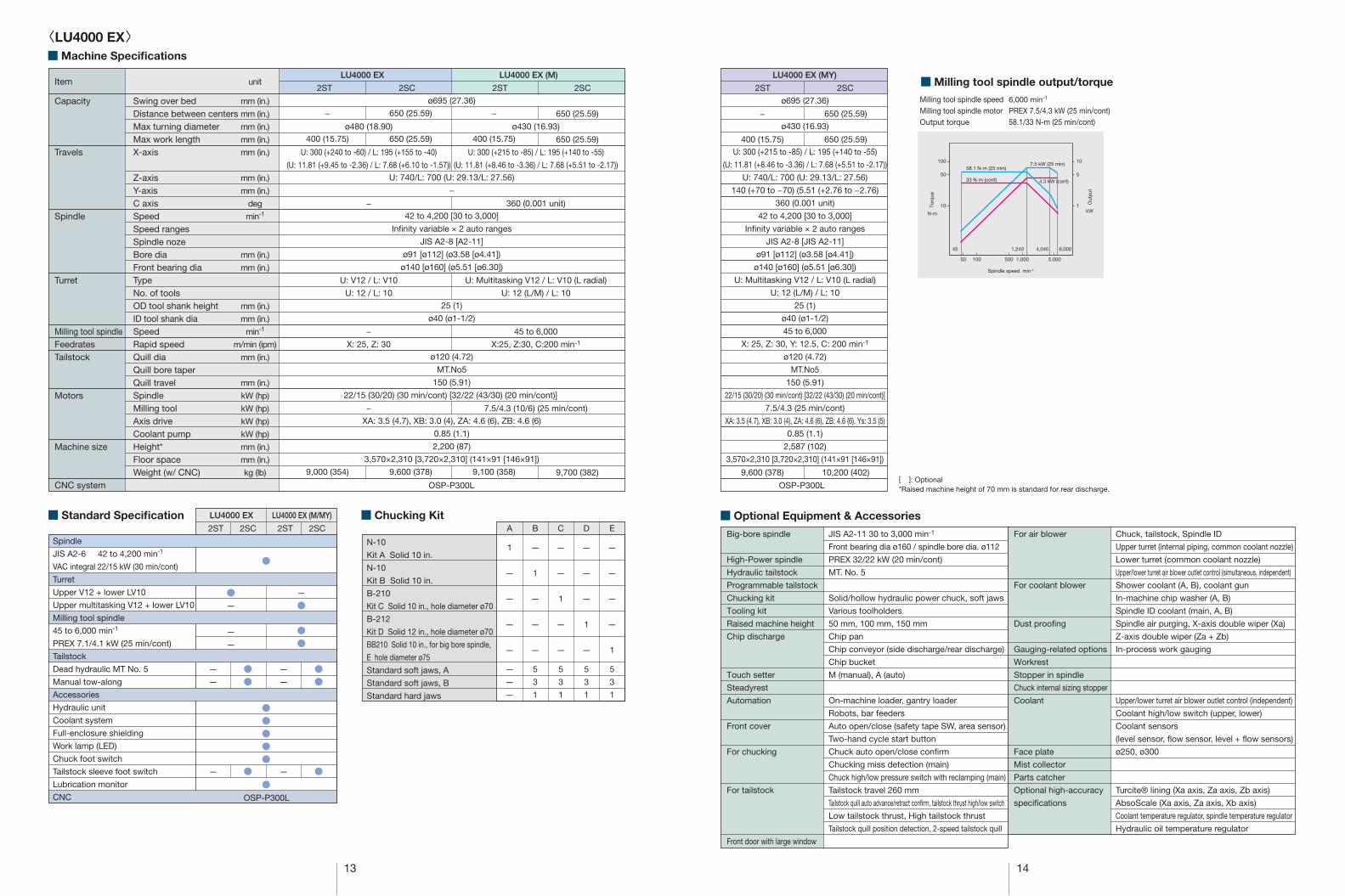
[ ]: Optional*Raised machine height of 70 mm is standard for rear discharge.
Milling tool spindle speed 6,000 min-1
Milling tool spindle motor PREX 7.5/4.3 kW (25 min/cont)Output torque 58.1/33 N-m (25 min/cont)
■ Milling tool spindle output/torque
−
400 (15.75)
9,600 (378)
650 (25.59)
650 (25.59)
10,200 (402)
LU4000 EX LU4000 EX (M)
ø695 (27.36)
ø430 (16.93)
U: 300 (+215 to -85) / L: 195 (+140 to -55)
(U: 11.81 (+8.46 to -3.36) / L: 7.68 (+5.51 to -2.17))
U: 740/L: 700 (U: 29.13/L: 27.56)
140 (+70 to −70) (5.51 (+2.76 to −2.76)
360 (0.001 unit)
42 to 4,200 [30 to 3,000]
In�nity variable × 2 auto ranges
JIS A2-8 [JIS A2-11]
ø91 [ø112] (ø3.58 [ø4.41])
ø140 [ø160] (ø5.51 [ø6.30])
U: Multitasking V12 / L: V10 (L radial)
U: 12 (L/M) / L: 10
25 (1)
ø40 (ø1-1/2)
45 to 6,000
X: 25, Z: 30, Y: 12.5, C: 200 min-1
ø120 (4.72)
MT.No5
150 (5.91)
22/15 (30/20) (30 min/cont) [32/22 (43/30) (20 min/cont)]
7.5/4.3 (25 min/cont)
XA: 3.5 (4.7), XB: 3.0 (4), ZA: 4.6 (6), ZB: 4.6 (6), Ys: 3.5 (5)
0.85 (1.1)
2,587 (102)
3,570×2,310 [3,720×2,310] (141×91 [146×91])
LU4000 EX (MY)
ø695 (27.36)
U: 740/L: 700 (U: 29.13/L: 27.56)
−
42 to 4,200 [30 to 3,000]
In�nity variable × 2 auto ranges
JIS A2-8 [A2-11]
ø91 [ø112] (ø3.58 [ø4.41])
ø140 [ø160] (ø5.51 [ø6.30])
25 (1)
ø40 (ø1-1/2)
ø120 (4.72)
MT.No5
150 (5.91)
22/15 (30/20) (30 min/cont) [32/22 (43/30) (20 min/cont)]
XA: 3.5 (4.7), XB: 3.0 (4), ZA: 4.6 (6), ZB: 4.6 (6)
0.85 (1.1)
2,200 (87)
3,570×2,310 [3,720×2,310] (141×91 [146×91])
−
400 (15.75)
9,000 (354)
−
400 (15.75)
9,100 (358)
650 (25.59)
650 (25.59)
9,700 (382)
ø430 (16.93)
U: 300 (+215 to -85) / L: 195 (+140 to -55)
(U: 11.81 (+8.46 to -3.36) / L: 7.68 (+5.51 to -2.17))
360 (0.001 unit)
U: Multitasking V12 / L: V10 (L radial)
U: 12 (L/M) / L: 10
45 to 6,000
X:25, Z:30, C:200 min-1
7.5/4.3 (10/6) (25 min/cont)
ø480 (18.90)
U: 300 (+240 to -60) / L: 195 (+155 to -40)
(U: 11.81 (+9.45 to -2.36) / L: 7.68 (+6.10 to -1.57))
−
U: V12 / L: V10
U: 12 / L: 10
−
X: 25, Z: 30
−
650 (25.59)
650 (25.59)
9,600 (378)
●—
—
●
—
—
—
—●●
—
—●●
— ● — ●
●●
●
●
●●●●●
LU4000 EX LU4000 EX (M/MY)
Spindle
JIS A2-6 42 to 4,200 min-1
VAC integral 22/15 kW (30 min/cont)
Turret
Upper V12 + lower LV10
Upper multitasking V12 + lower LV10
Milling tool spindle
45 to 6,000 min-1
PREX 7.1/4.1 kW (25 min/cont)
Tailstock
Dead hydraulic MT No. 5
Manual tow-along
Accessories
Hydraulic unit
Coolant system
Full-enclosure shielding
Work lamp (LED)
Chuck foot switch
Tailstock sleeve foot switch
Lubrication monitor
CNC
A
1
—
—
—
—
—
—
—
B
—
1
—
—
—
5
3
1
C
—
—
1
—
—
5
3
1
D
—
—
—
1
—
5
3
1
N-10
Kit A Solid 10 in.
N-10
Kit B Solid 10 in.
B-210
Kit C Solid 10 in., hole diameter ø70
B-212
Kit D Solid 12 in., hole diameter ø70
BB210 Solid 10 in., for big bore spindle,
E hole diameter ø75
Standard soft jaws, A
Standard soft jaws, B
Standard hard jaws
E
—
—
—
—
1
5
3
1
<LU4000 EX>■ Machine Specifications
Item
Capacity
Travels
Spindle
Turret
Milling tool spindleFeedratesTailstock
Motors
Machine size
CNC system
Swing over bedDistance between centersMax turning diameterMax work lengthX-axis
Z-axisY-axisC axisSpeedSpeed rangesSpindle nozeBore diaFront bearing diaTypeNo. of toolsOD tool shank heightID tool shank diaSpeedRapid speedQuill diaQuill bore taperQuill travelSpindleMilling toolAxis driveCoolant pumpHeight*Floor spaceWeight (w/ CNC)
unit
mm (in.)
mm (in.)
mm (in.)
mm (in.)
mm (in.)
mm (in.)
mm (in.)
deg
min-1
mm (in.)
mm (in.)
mm (in.)
mm (in.)
min-1
m/min (ipm)
mm (in.)
mm (in.)
kW (hp)
kW (hp)
kW (hp)
kW (hp)
mm (in.)
mm (in.)
kg (lb)
■ Standard Specification ■ Chucking Kit
2ST 2SC 2ST 2SC 2ST 2SC
OSP-P300L OSP-P300L
2ST 2SC 2ST 2SC
OSP-P300L
■ Optional Equipment & Accessories
JIS A2-11 30 to 3,000 min-1
Front bearing dia ø160 / spindle bore dia. ø112
PREX 32/22 kW (20 min/cont)
MT. No. 5
Solid/hollow hydraulic power chuck, soft jaws
Various toolholders
50 mm, 100 mm, 150 mm
Chip pan
Chip conveyor (side discharge/rear discharge)
Chip bucket
M (manual), A (auto)
On-machine loader, gantry loader
Robots, bar feeders
Auto open/close (safety tape SW, area sensor)
Two-hand cycle start button
Chuck auto open/close con�rm
Chucking miss detection (main)
Chuck high/low pressure switch with reclamping (main)
Tailstock travel 260 mm
Tailstock quill auto advance/retract con�rm, tailstock thrust high/low switch
Low tailstock thrust, High tailstock thrust
Tailstock quill position detection, 2-speed tailstock quill
Big-bore spindle
High-Power spindle
Hydraulic tailstock
Programmable tailstock
Chucking kit
Tooling kit
Raised machine height
Chip discharge
Touch setter
Steadyrest
Automation
Front cover
For chucking
For tailstock
Front door with large window
Chuck, tailstock, Spindle ID
Upper turret (internal piping, common coolant nozzle)
Lower turret (common coolant nozzle)
Upper/lower turret air blower outlet control (simultaneous, independent)
Shower coolant (A, B), coolant gun
In-machine chip washer (A, B)
Spindle ID coolant (main, A, B)
Spindle air purging, X-axis double wiper (Xa)
Z-axis double wiper (Za + Zb)
In-process work gauging
Upper/lower turret air blower outlet control (independent)
Coolant high/low switch (upper, lower)
Coolant sensors
(level sensor, °ow sensor, level + °ow sensors)
ø250, ø300
Turcite® lining (Xa axis, Za axis, Zb axis)
AbsoScale (Xa axis, Za axis, Xb axis)
Coolant temperature regulator, spindle temperature regulator
Hydraulic oil temperature regulator
For air blower
For coolant blower
Dust proo�ng
Gauging-related options
Workrest
Stopper in spindle
Chuck internal sizing stopper
Coolant
Face plate
Mist collector
Parts catcher
Optional high-accuracy
speci�cations
Out
put
Torq
ue
50 100 500 1,000 5,000
100
50
10
10
5
1
45 1,240 4,040 6,000
N-m
Spindle speed min-1
kW
7.5 kW (25 min)
4.3 kW (cont)
58.1 N-m (25 min)
33 N-m (cont)
15 16
■ Tooling System
E
6
4
8
—
—
—
4
4
—
—
—
1
—
D
8
6
10
2
2
2
4
4
2
1
1
1
—
2ST 2SC
E
8
2
8
—
—
—
4
4
—
—
—
1
1
D
10
4
10
2
2
2
4
4
2
1
1
1
1
OD-IOD-IIID-H40
BS 10-H40
BS 12-H40
BS 16-H40
BS 20-H40
BS 25-H40
BS 32-H40
DS MT No. 1-H40
DS MT No. 2-H40
DS MT No. 3-H40
Axial drill/mill unit
Radial drill/mill unit
Dummy holder
Revolving center MT No. 5
E
6
2
8
—
—
—
4
4
—
—
—
1
2
2
3
—
D
8
4
10
2
2
2
4
4
2
1
1
1
4
3
3
—
E
6
2
8
—
—
—
4
4
—
—
—
1
2
2
3
1
D
8
4
10
2
2
2
4
4
2
1
1
1
3
4
3
1
2SC 2ST
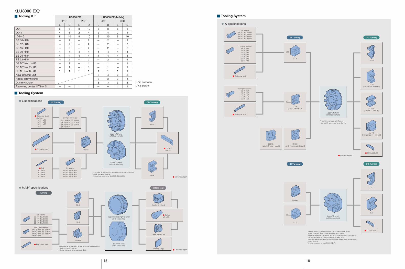
LU3000 EX LU3000 EX (M/MY)
● W speci�cations
Drill sleevesDS MT No.1-H40DS MT No.2-H40DS MT No.3-H40DS MT No.4-H40
● Commercial part
ID II-S(main ID or sub ID)
ID IV-S(main ID 2 tools + sub ID)
Boring bar sleevesBS 8-H40BS 10-H40BS 12-H40BS 16-H40BS 20-H40BS 25-H40BS 32-H40
● Boring bar ø20
● Boring bar ø40
Boring bar sleevesBS 6-H20BS 8-H20BS 10-H20BS 12-H20BS 16-H20
ID III-S(main ID 2 tools or main ID + sub ID)
ID I-S
Upper V12 turret(ø400 across flats)
OD III-S(main OD + sub OD)
ø40
ø20
ID Turning OD Turning
ID Turning OD Turning
ID-H40
OD I-S
OD II-S(main or sub axial face)
OD V-S(sizing stopper + sub OD)
Lower V8 turret (ø300 across flats)
OD I
OD II
● OD tool 25 × 25
● OD tool 25x25
ID I-S
ø40
E Kit: Economy
D Kit: Deluxe
<LU3000 EX>■ Tooling Kit
■ Tooling System
● L speci�cations
● M/MY speci�cations
ID Turning OD Turning
* When using an oil hole drill or oil hole boring bar, please select oilhole ID tool specs (optional)
* A holder is as common as LB3000 EXII (L), LU300.● Commercial part
* When using an oil hole drill or oil hole boring bar, please select oilhole ID tool specs (optional)
* A holder is as common as LB3000 EXII (M).
Turning
● Commercial part
● Boring bar shank diameter
● DrillMT No.1MT No.2MT No.3MT No.4
Drill sleevesDS MT No.1-H40DS MT No.2-H40DS MT No.3-H40DS MT No.4-H40
● Boring bar ø40 ID-H40
OD I
OD II
Upper V12 turret(ø400 across flats)
Lower V8 turret(ø300 across flats)
Boring bar sleeves
BS 8-H40 BS 20-H40 BS 10-H40 BS 25-H40BS 12-H40 BS 32-H40BS 16-H40
ø 8 ø20ø10 ø25ø12 ø32ø16
Axial drill/ mill unit
Dummy (Plug)
Drill sleeves
Boring bar sleeves
DS MT No.1-H40DS MT No.2-H40DS MT No.3-H40DS MT No.4-H40
BS 8-H40 BS 20-H40BS 10-H40 BS 25-H40BS 12-H40 BS 32-H40BS 16-H40
● Boring bar ø40
Radial drill/mill unit
Milling tool
OD-I
OD-II
ID-H40
Upper multitasking V12 turret(ø340 across flats)
Lower V8 turret(ø280 across flats)
● Colletsø2~ø20
● OD tool25 × 25
*Machining on sub-spindle side done with upper and lower turrets
* Sleeves (except for H20) are used for both upper and lower turrets* Lower turret OD I, II and ID-H40 are shared with L specs.* Please be aware that interference with sub-spindle due may occur during part
transfer depending on the state of tooling on upper turret.* When using an oil hole drill or oil hole boring bar, please select oil hole ID tool
specs (optional)* A holder is as common as LB3000 EXII (W).
17 18
■ Tooling System
E
6
4
8
—
—
—
4
4
—
—
—
1
—
D
8
6
10
2
2
2
4
4
2
1
1
1
—
E
8
2
8
—
—
—
4
4
—
—
—
1
1
D
10
4
10
2
2
2
4
4
2
1
1
1
1
E
6
2
8
—
—
—
4
4
—
—
—
1
2
2
3
—
D
8
4
10
2
2
2
4
4
2
1
1
1
4
3
3
—
E
6
2
8
—
—
—
4
4
—
—
—
1
2
2
3
1
D
8
4
10
2
2
2
4
4
2
1
1
1
3
4
3
1
2ST 2SC2SC 2ST
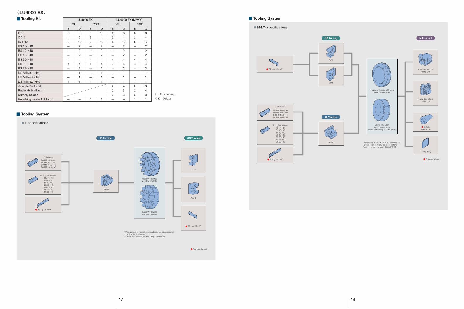
● L specications
● Commercial part
DS MT No.1-H40DS MT No.2-H40DS MT No.3-H40DS MT No.4-H40
Drill sleeves
● Boring bar ø40
ID-H40
Boring bar sleevesBS 8-H40BS 10-H40BS 12-H40BS 16-H40BS 20-H40BS 25-H40BS 32-H40
OD I
OD II
Upper V12 turret(ø460 across flats)
Lower V10 turret(ø370 across flats)
ID Turning OD Turning
DS MT No.1-H40DS MT No.2-H40DS MT No.3-H40DS MT No.4-H40
Drill sleeves
● Boring bar ø40
Boring bar sleevesBS 8-H40BS 10-H40BS 12-H40BS 16-H40BS 20-H40BS 25-H40BS 32-H40
● M/MY specications
OD Turning
ID Turning
Milling tool
● Commercial part
OD I
ID-H40
Axial drill/ mill unitholder unit
Radial drill/mill unitholder unit
Dummy (Plug)
● Colletsø4 to ø26
OD II
Upper multitasking V12 turret(ø380 across flats)
Lower V10 turret(ø380 across flats)
* Only a lathe-turning tool can be used.
<LU4000 EX>■ Tooling Kit
■ Tooling System
LU4000 EX LU4000 EX (M/MY)
E Kit: Economy
D Kit: Deluxe
OD-IOD-IIID-H40
BS 10-H40
BS 12-H40
BS 16-H40
BS 20-H40
BS 25-H40
BS 32-H40
DS MTNo.1-H40
DS MTNo.2-H40
DS MTNo.3-H40
Axial drill/mill unit
Radial drill/mill unit
Dummy holder
Revolving center MT No. 5
● OD tool 25 × 25
● OD tool 25 × 25
* When using an oil hole drill or oil hole boring bar, please select oilhole ID tool specs (optional)
* A holder is as common as LB4000EXII (L) and LU400.
* When using an oil hole drill or oil hole boring bar, please select oil hole ID tool specs (optional)
* A holder is as common as LB4000EXII (M).
19
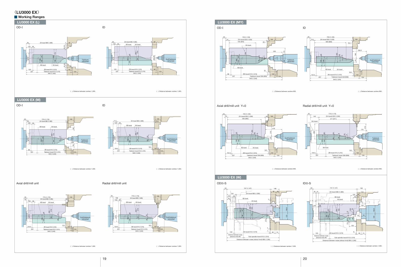
■ Working Ranges
OD-I ID
OD-I ID
Axial drill/mill unit Radial drill/mill unit
( ): Distance between centers 1,000. ( ): Distance between centers 1,000.
( ): Distance between centers 1,000. ( ): Distance between centers 1,000.
( ): Distance between centers 1,000. ( ): Distance between centers 1,000.
ODIII-S IDIII-S
( ): Distance between centers 1,000.
20
OD-I ID
Axial drill/mill unit Y=0 Radial drill/mill unit Y=0
( ): Distance between centers 950. ( ): Distance between centers 950.
( ): Distance between centers 950. ( ): Distance between centers 950.
( ): Distance between centers 1,000.
<LU3000 EX>
170
9026
0
709016
0 Tailstockretracted
Tailstockretracted
39103
940 (1,340)Tailstock travel 615 (1,015) 124201
122 ZB travel 615 (1,015)
XB travel XA travel
55 7
7 82
82
3535
3535
ø210
ZA travel 685 (1,085)
210
5026
0
3013
016
0
39103
124201123 ZB travel 615 (1,015)
ZA travel 685 (1,085)
XA travelXB travel
56 6
6 82
82
ø210
4948
Tailstock travel 615 (1,015)940 (1,340)
190
7026
0
3013
0160
39103ZA travel 685 (1,085)71.5 16.5
100
5529
ø210
Tailstock travel 615 (1,015)201
104.5 ZB travel 615 (1,015)16.5
100
XA travelXB travel
940 (1,340)124
170
9026
0
5011
016
0
39103ZA travel 685 (1,085)55 7
100773 (1,173)50
35
200
35
179
XA travelXB travel
ø210
940 (1,340)Tailstock travel 615 (1,015) 124201
88 ZB travel 615 (1,015) 7
210
5026
0
3013
0160
39103ZA travel 685 (1,085)32 56
100773 (1,173)50
7529
ø210
Tailstock travel 615 (1,015) 124201
104.5 ZB travel 615 (1,015)16.5
100
XA travelXB travel
940 (1,340)
213
4326
0
3013
0160
39103ZA travel 685 (1,085)138
100773 (1,173)50
3029
ø210
Tailstock travel 615 (1,015) 124201
104.5 ZB travel 615 (1,015)16.5
100
XA travelXB travel
940 (1,340)
XB travel
57 100445 (845)
50 720 (1,120)
940 (1,340)
ZB travel 615 (1,015)
Tailstock travel 559 (959)25788
124
33
100
XA travel
33
ZA travel 630 (1,030)
260
253
170
90160
110
50
616 6
7
73.5 ZA travel 630 (1,030)
565 (965)
940 (1,340)
50 720 (1,120)
100
16.5
236.5
190
260
160
130
30
1429
70
ZB travel 615 (1,015)
XB travel XA travel
Tailstock travel 559 (959)257104.5
124
16.5
100
XB travel
XA travel
140 ZA travel 630 (1,030)
511 (911)
50 770 (1,170)
940 (1,340)
ZB travel 615 (1,015)
Tailstock travel 559 (959)257
260
104.5
124
16.5
100
170
213
160
130
30 24 8
20 14
64 35
34 ZA travel 630 (1,030)
565 (965)
940 (1,340)
50 720 (1,120)
10056
276
21026
0
160
130
30
1429
50
ZB travel 615 (1,015)
XB travel XA travel
Tailstock travel 559 (959)257
104.5
124
16.5
100
ZA travel 685 (1,085)
747 (1,147)
XA travel
XB travel
50
122 82 747
154
55
103 39
148
82 66
4
4
160
9070
260
110
150
120
27.5
10
27
25.5
138.
6
ZB travel 610 (1,010)
Sub-spindle travel 610 (1,010)
Distance between noses (retract limit) 895 (1,295)
Distance between noses(advance end) 285
Sub-spindle travel 610 (1,010)
Distance between noses (retract limit) 895 (1,295)
Distance between noses(advance end) 285
7629
ZA travel 685 (1,085)
747 (1,147)50
103 39
56 44 110
148
XA travel
XB travel
160
130
30 260
9516
5
123 82 746
ZB travel 610 (1,010)
120
2.5
60.5
31
2026
19.5
36
120
138.
6
15
60
60
100 38
6
100
7629
Tailstockretracted
Tailstockretracted
Quill/tailstockretracted
Quill/tailstockretracted
Quill/tailstockretracted
Quill/tailstockretracted
Quill/tailstockretracted
Quill/tailstockretracted
LU3000 EX (MY)
LU3000 EX (W)
LU3000 EX (L)
LU3000 EX (M)
21 22
43
Standard spindle nose position
11368 7 90ZA travel 740
95
1,045
Tailstock travel 700
ZB travel 700103 927
209 136
205
7512
0
3535
195
XB
tra
vel
300
XA
tra
vel
3535
43
Standard spindle nose position
11369 6 90ZA travel 740
85
1,045
Tailstock travel 700
ZB travel 700104 926
209 136
215
6513
0
195
XB
tra
vel
300
XA
tra
vel
35
826
43
Standard spindle nose position
113
53
54
7
ZA travel 740
85
1,045
Tailstock travel 700
ZB travel 70082
209
215
5514
0
195
XB
tra
vel
300
XA
tra
vel
35
7
136
43
Standard spindle nose position
1137054 ZA travel 740
3516
0
195
XB tr
avel 43
62
16 110
65
209 136
235
300
XA
tra
vel
1,045
Tailstock travel 700
ZB travel 70099 16 110
826
Standard spindle nose position
6024
0
300
XA
tra
vel
2954
ZA travel 740
3516
0
195
XB
tra
vel
209
1,045
Tailstock travel 700
ZB travel 70099
287
4311357 110
136
16 110
826
Standard spindle nose position
43113141
110
ZA travel 740
44
209 136
256
3516
0
195
XB
tra
vel
300
XA
tra
vel
1,045
Tailstock travel 700
ZB travel 70099 16 110
54
826
Standard spindle nose position
43
53 33
54 110
7113
ZA travel 740
195
XB
tra
vel
254 136
1,045
Tailstock travel 655
ZB travel 70082 11033
140
55
252
3535
8521
5
300
XA
tra
vel
7
6523
5
300
XA
tra
vel
826
Standard spindle nose position
43
70 16
54 110
113
ZA travel 740
195
XB
tra
vel
160
35
254 136
1,045
Tailstock travel 655
ZB travel 70099 110
16
6024
0
300
XA
tra
vel
826
Standard spindle nose position
29 57
54 110
ZA travel 740
195
XB
tra
vel
160
35
254 136
1,045
Tailstock travel 655
ZB travel 70099 11016
43113
826
Standard spindle nose position
110
ZA travel 740
43
141
54
113
195
XB
tra
vel
160
35
254 136
1,045
Tailstock travel 655
ZB travel 70099 11016
4425
6
300
XA
tra
vel
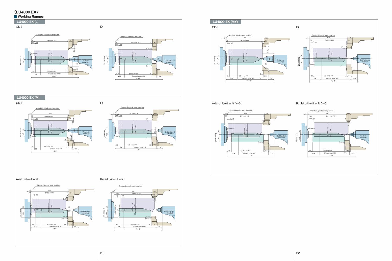
■ Working Ranges
Tailstockretracted
Tailstockretracted
Quill/tailstockretracted
Quill/tailstockretracted
Quill/tailstockretracted
Quill/tailstockretracted
Tailstockretracted
Tailstockretracted
Quill/tailstockretracted
Quill/tailstockretracted
<LU4000 EX>
ID
LU4000 EX (MY)LU4000 EX (L)
LU4000 EX (M)
OD-I
OD-I ID
Axial drill/mill unit Radial drill/mill unit
OD-I ID
Axial drill/mill unit Y=0 Radial drill/mill unit Y=0
23 24
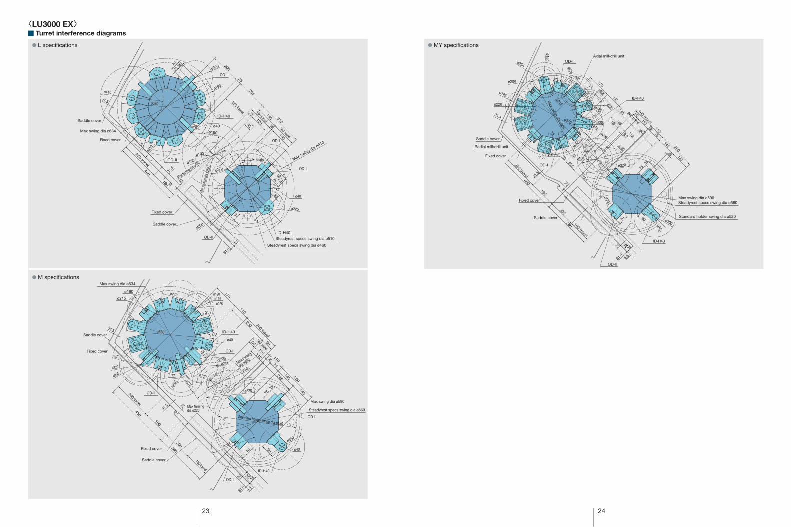
■ Turret interference diagrams
● L speci�cations ● MY speci�cations
● M speci�cations
200
205
35
70
3535
OD-I
ø580
ø410ø190
ø220
Max swing dia ø634
Saddle cover
Fixed cover
31.5
180
440
OD-II
OD-II
OD-I
ID-H40
ID-H40
30
260 travel
260 travel
57
ø40
ø210
ø250
ø190
ø225
Max turning dia ø410Max swing dia ø610
ø160
ø100
Steadyrest specs swing dia ø460
Steadyrest specs swing dia ø510
Saddle cover
Fixed cover
30
6.5
31.5
31.5
310
160 travel
150
150
3512555
OD-I
160 travel
7035
35
ø40
ø260
ø225
Max
turn
ing d
ia ø2
50
30
35
OD-II
190
200
450
360
260 travel
Max swing dia ø634
ø190
ø215
ø220
ø270
ø255
Saddle cover
Fixed cover
Fixed cover
31.5
31.5
Saddle cover
70
90
ø40
OD-I
Max turningdia ø220
Standard holder swing dia ø520
170
ID-H40
75 35
77
ø225ø235
ø240
ø220
ø275
ø580
ø130
ø190ø195ø225
30
ø40
ø300
Max turning
dia ø340
Max swing dia ø590
Steadyrest specs swing dia ø560
110
248
112
280
9050
35
110
75
140
140
110
280
OD-I
260 travel160 travel
ø160
OD-II
7535
9070
7
ø295
ø320
160 travel ID-H40
31.5
35 5520
6.5
ø235
ø205ø185
ø220
ø254
ø200
ø160
170
132
260 travel450
190
86.6
65
21.5
20
21.4
OD-IIAxial mill/drill unit
ID-H40
Fixed cover
Fixed cover
Saddle cover
Radial mill/drill unit
OD-I
110
Max sw
ing dia ø604
ø160
ø296
ø215
ø570
ø20
ø235
280
138.8
148
160 travel
67
75
35
ø20
5070
70
120 S
T
ø174
ø185
ø220ø40
50110
140
140
1129.2
260 travel110
280
ø130
ø220
ø300
ø320
ø40220
3575
25
173.4
35
75
90
Max swing dia ø590Steadyrest specs swing dia ø560
Standard holder swing dia ø520
ID-H40
OD-II
ø295
160 travel
360
200
70
7
Saddle cover
77
31.5
35 5520
6.5
57
<LU3000 EX>

57
25 26
■ Turret interference diagrams<LU4000 EX>● L speci�cations
● W speci�cations Sub-spindle ● M speci�cations
● W speci�cations Main spindle
310
OD III-S
ø225
31.5
6.5
ø230
ø240
ø200
ID III-S
ID IV-S
Fixed cover
Saddle cover
Max swing dia ø634
OD V-S
Steadyrest specs swing dia ø460
Max swing dia ø610Steadyrest specs swing dia ø510
OD II
Saddle cover
Fixed cover
160 travel
54.5
310
44085
200
155
150
ø210
ø240
ø225
ø20
ø245
10
45
12.575
ID I-S
OD II-SID II-S
OD I-S
OD I
160 travel
150
35
35
35
33
50
125
ø580
ø220ø40
260 travel
180
30
25
440
ø260260 travel
ø210
ø280
ø320
35
OD I-S
ID-H40
45
12.5
70
8555
35
30
55105
ø260
ø250
ø220
ø260ø110
ø160
Max turning dia ø410
Max turning dia ø250
ø20
57
3535
ø250
ø225
30
50
260 travel
7548
7
ø120ø120
Max turning dia ø410
ID III-S
ID II-S
OD II-S
ø160 (Byte projection 35 mm)
75
75
200
20
55
55
ø17535
35
35
Max sw
ing dia ø634
OD III-S
OD V-S
54.533
200102
ø130
55
5035
ID IV-S
ID I-S
OD I-S
195 travel
300 travel
185
35
40
35
230
155 375
505
Spindle center
ø245
ø260
ø215
ø650
ø530
ø250
Max swing dia ø766 (ZA Saddle cover)
OD-I
ZA Saddle cover
Max swing dia ø703 (ZA Fixed cover)
ZA Fixed cover
Max turning dia ø436
OD-II
Max turning dia ø410
Max
turn
ing d
ia ø4
80 (U
pper
turre
t)
ID-H4035
35
60 35
70
Max turning dia ø310
(Lower turret)
ø240
ø245
ø255
ø260
ø250
ø40
Swing
ove
r bed
ø69
5
Max turning dia ø266
OD-II
60 3570
6035
35
240
Max turning dia ø240
ø230
ø255
ø560
ø285
ø260
57
ZB Saddle cover
ZB Fixed cover
Max swing dia ø690
ID-H40
OD-I
300 travel 85
35
75
190
110
215
40
ø235
ø266
ø252
ø26
ø207
ø230
90
Max swing dia ø766 (ZASaddle cover)
OD-II
ZA Fixed cover
ZA Saddle cover
Max swing dia ø703 (ZAFixed cover)
Axial mill/drill unit
OD-I
ID-H40
195 travel
160
110
55140
7535
410
515
90
8574
76
Swing
ove
r bed
ø69
5
Max
turn
ing d
ia ø4
30 (U
pper
turre
t)
Max turning dia ø496
ø633
ø235
ø210
ø245
ø63
29
35
Spindle center
Max turning dia ø280 (Lower turret)
ø260
ø275
ø558
ø285
ø255
ø310
ø40
ø240
29
Max turning dia ø346
OD-II
OD-I
ZB Saddle cover
ZB Fixed cover
77
3575
ø260
Max swing dia ø650
ID-H40
27 28
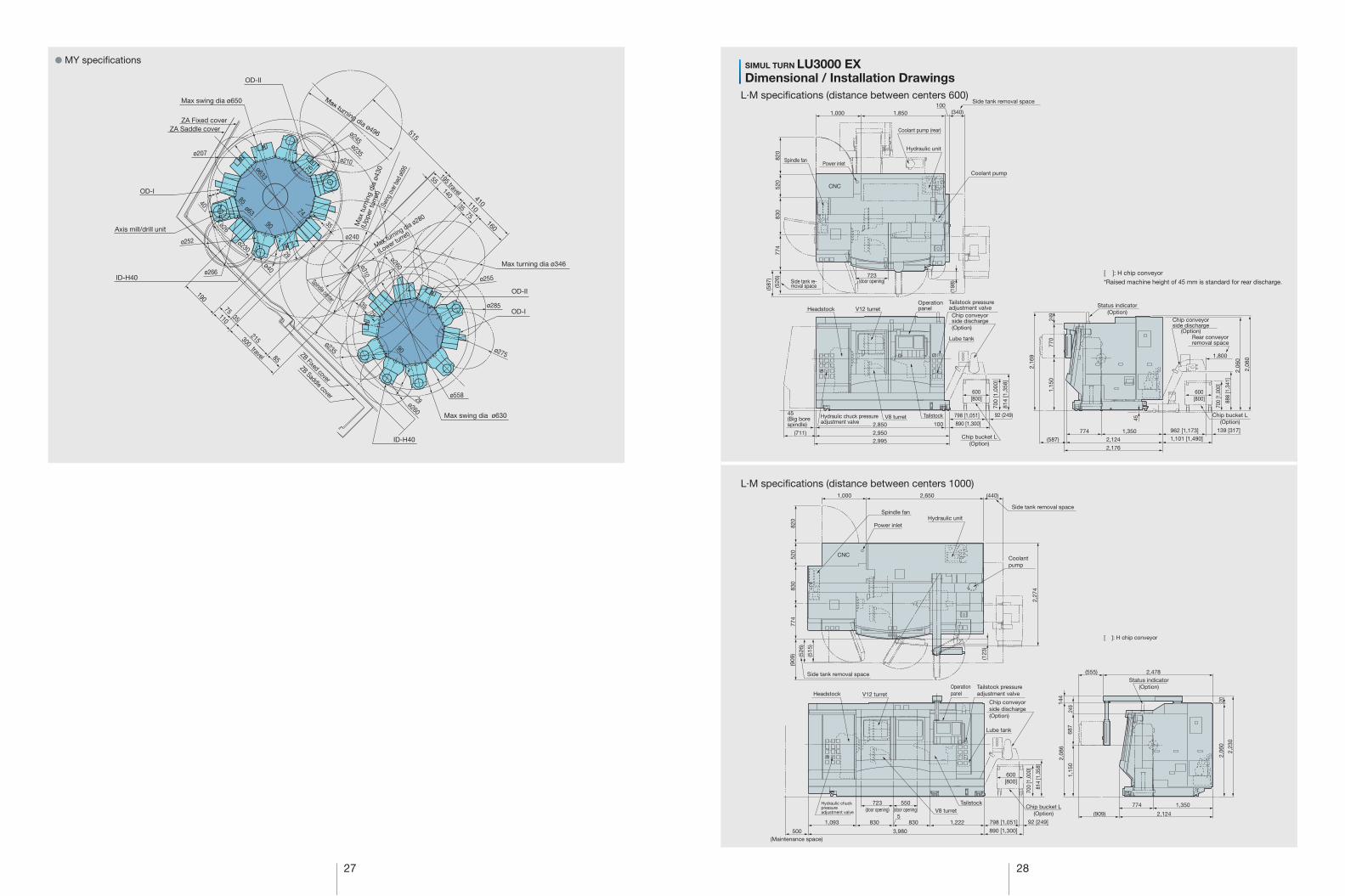
L·M speci�cations (distance between centers 1000)
SIMUL TURN LU3000 EX● MY speci�cations
L·M speci�cations (distance between centers 600)
OD-II
ZB Saddle cover
ZB Fixed cover
ZA Saddle coverZA Fixed cover
OD-I
Axis mill/drill unit
Max swing dia ø650
300 travel 85
35
75
190
110
215
ID-H40ø266
ø252
ø207
ø235
Max turning dia ø496
ø633
ø40
515
29
ø230
74
35
76
ø235
ø210
ø245
8540
ø26
ø63
Swing
over
bed ø
695
Max
turn
ing
dia
ø430
(Upp
er tu
rret
)
Max turning dia ø280
(Lower turret)
ø260ø310
195 travel
160
110
55140
7535
410
Max turning dia ø346
90
3575
Spindle center
ø240
ø275
ø285
ø255
OD-II
OD-I
ø260
29
90
ø558
Max swing dia ø630
ID-H40
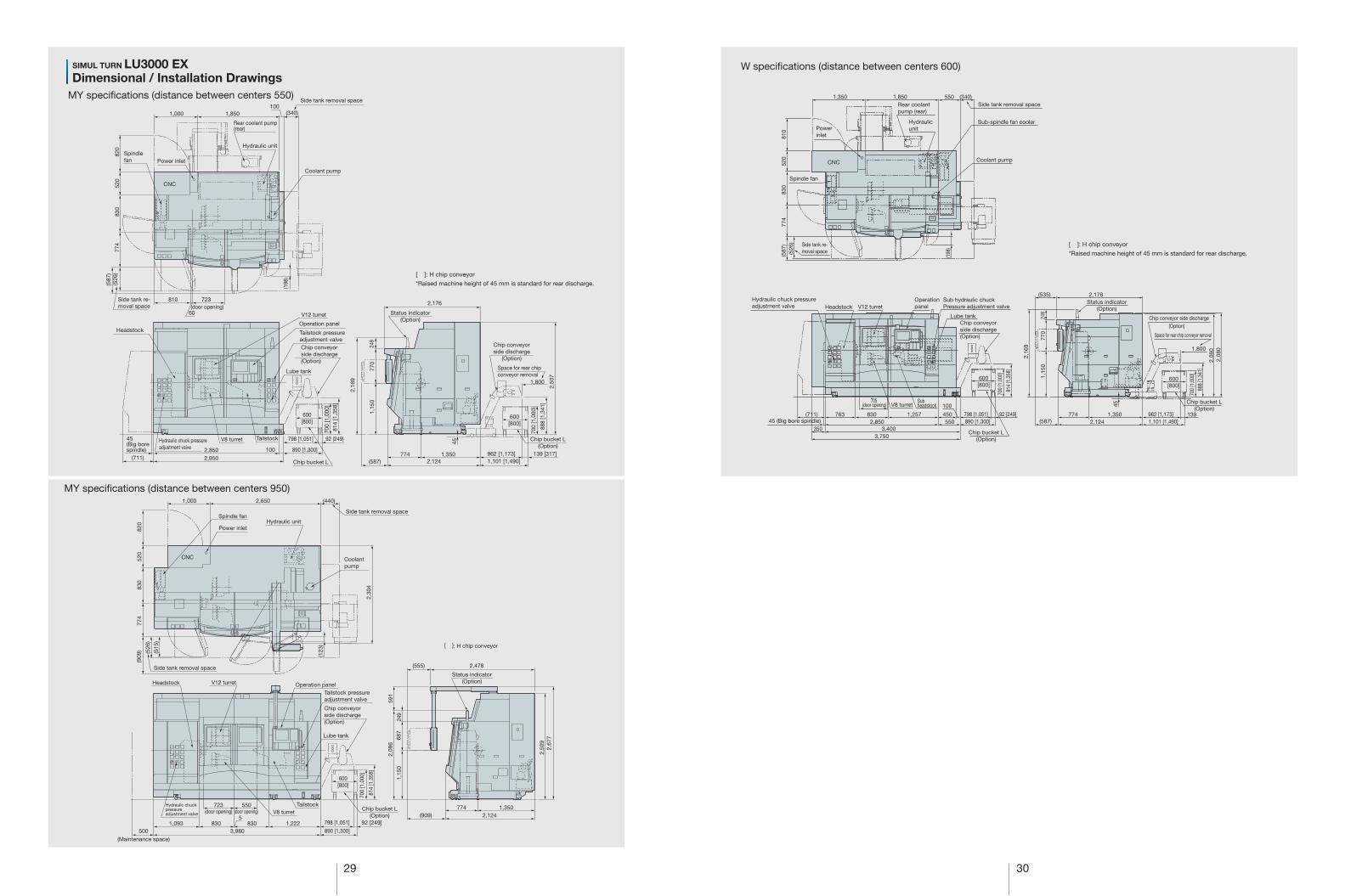
Dimensional / Installation Drawings
[ ]: H chip conveyor*Raised machine height of 45 mm is standard for rear discharge.
830
774
(587
)
(526
)52
082
0
723(door opening)
1,000
Coolant pump (rear)
Side tank removal space
Coolant pump
100(340)
(198
)
Power inlet
Hydraulic unit
Side tank re-moval space
1,850
CNC
Spindle fan
V8 turret
V12 turretHeadstockOperationpanel
Lube tank
Tailstock
Tailstock pressureadjustment valveChip conveyorside discharge(Option)
798 [1,051]
890 [1,300]2,850
45(Big borespindle) 100
2,950(711)2,995
Chip bucket L(Option)
92 (249)
700
[1,0
00]
814
[1,3
58]
600[800]
Hydraulic chuck pressureadjustment valve
Chip bucket L(Option)
2,16
9
1,15
077
024
9
1,350
45
774
2,124(587) 1,101 [1,490]962 [1,173] 139 [317]
2,176
Status indicator(Option)
Chip conveyorside discharge
(Option)
700
[1,0
00]
888
[1,3
41]
600[800]
2,06
0
2,08
01,800
830
774
520
820
Coolantpump
(909
) (526
)
(515
)
(123
)
Power inlet
Spindle fanHydraulic unit
1,000
Side tank removal space
(440)2,650
CNC
2,27
4
Side tank removal space
[ ]: H chip conveyor
V8 turret
V12 turretHeadstockOperationpanel
Lube tank
Tailstock
Tailstock pressureadjustment valve
Chip conveyorside discharge(Option)
890 [1,300]
(909)
(555)
798 [1,051] 92 [249]1,093 1,222830
723(door opening)
550(door opening)
8305
(Maintenance space)500 3,980
Chip bucket L(Option)
700
[1,0
00]
814
[1,3
58]
600[800]
Hydraulic chuckpressureadjustment valve
2,08
614
4
1,15
068
724
9
2,124
2,478
774 1,350
Status indicator(Option)
2,06
020
2,23
0
Rear conveyorremoval space
29 30
MY speci�cations (distance between centers 950)
W speci�cations (distance between centers 600)
Sub-spindle fan cooler
(198
)
(587
)(5
26)
(340)1,8501,350 550
774
830
520
810
Sub hydraulic chuckPressure adjustment valve
Subheadstock
3,7503,400
2,850350
763 830 450550
100
1,257
705 (door opening)
(711)890 [1,300]798 [1,051]
700
[1,0
00]
814
[1,3
58]
92 [249]
[800]600
2,124774 139 1,350
1,800
(587)
2,176
1,101 [1,490]962 [1,173]
249
770
45
1,15
0
2,16
9
2,06
02,
080
(535)
700
[1,0
00]
888
[1,3
41]
[800]600
SIMUL TURN LU3000 EX
MY speci�cations (distance between centers 550)
Dimensional / Installation Drawings
[ ]: H chip conveyor*Raised machine height of 45 mm is standard for rear discharge.
[ ]: H chip conveyor*Raised machine height of 45 mm is standard for rear discharge.
830
774
(587
)(5
26)
520
820
723
Spindlefan
1,000
Rear coolant pump(rear)
Side tank removal space
Coolant pump
100(340)
(198
)
810
60
Power inlet
Hydraulic unit
Side tank re-moval space
1,850
CNC
V8 turret
V12 turret
HeadstockOperation panel
Lube tank
Tailstock
Tailstock pressureadjustment valveChip conveyorside discharge(Option)
2,850
45(Big borespindle) 100
2,950(711)Chip bucket L
92 (249)
700
[1,0
00]
814
[1,3
58]
600[800]
Hydraulic chuck pressureadjustment valve
798 [1,051]
890 [1,300]
Chip conveyorside discharge
(Option)
Space for rear chipconveyor removal
700
[1,0
00]
888
[1,3
41]
600[800]
Chip bucket L(Option)
2,16
9
1,15
0
2,50
7
770
249
1,35045
7742,124(587) 1,101 [1,490]
1,800
962 [1,173] 139 [317]
2,176
Status indicator(Option)
830
774
520
820
Coolantpump
(909
) (526
)
(515
)
(123
)
Power inlet
Spindle fanHydraulic unit
1,000
Side tank removal space
(440)2,650
CNC
2,30
4
Side tank removal space
(door opening) (door opening) V8 turret
V12 turretHeadstock Operation panel
Lube tank
Tailstock
Tailstock pressureadjustment valve
890 [1,300]
798 [1,051] 92 [249]1,093 1,222830
723 550
8305
(Maintenance space)500 3,980
Chip bucket L(Option)
700
[1,0
00]
814
[1,3
58]
600[800]
Hydraulic chuckpressureadjustment valve (909) 2,124
(555) 2,478
774 1,350
Status indicator(Option)
[ ]: H chip conveyor
2,50
9
2,08
659
1
1,15
068
724
9
2,67
7
(door opening)
Chip conveyorside discharge(Option)
Side tank removal space
Coolant pump
Spindle fan
Rear coolantpump (rear)
Powerinlet
Hydraulicunit
CNC
Side tank re-moval space
V12 turretHeadstockHydraulic chuck pressureadjustment valve
Chip bucket L(Option)
Chip bucket L(Option)
Operationpanel
V8 turret
45 (Big bore spindle)
Lube tankChip conveyorside discharge(Option)
Chip conveyor side discharge(Option)
Space for rear chip conveyor removal
Status indicator(Option)

31 32
Power inlet (Height from �oor 1,539 mm)
(561
)(2
,310
)
(800
)
(500)70
(402
)
(114
)
(side discharge)
Coolant pump 0.85 kw
Hydraulic unitMechanical front door lock SW
2,310
820 180
1,000 2,500
820
521
919
839
V12 turret
Standard spindle nose position
1,100 837 (door opening)
85552
195(door travek)
V10 turret
500
150 (Big bore spindle)
3,570
3,500 70
4,290 [4,730]
650 [903] 70 [257]
(706)
[800]
(side discharge)Lubricant collection bucket
1,440839
1,23
586
5
2,10
024
9
2,34
9
600
2,20
0
700
[1,0
00]
817
[1,3
61]
1,120870 320
Power inlet (Height from �oor 1,539 mm)
(561
)(2
,310
)
(800
)
(500)70
(402
)
(114
)
(side discharge)
Coolant pump 0.85 kw
Hydraulic unitMechanical front door lock SW
Standard spindle nose position
820 180
1,000 2,500
820
521
919
839
1,100 837 (door opening)
85552
195
(door travek)
V12 turret
V10 turret Hydraulictailstock (706) 1,440839
4,290 [1,000]
650 [903] 70[257]
500
150 (Big bore spindle)
3,570
3,500 70
1,420870 202,310
2,58
7
2,53
057
100
2,10
0
[800]600
700
[1,0
00]
817
[1,3
61]
1,23
586
5
330
MY speci�cations (distance between centers 650)SIMUL TURN LU4000 EX
L·M speci�cations (distance between centers 650)
Dimensional / Installation Drawings
CNC CNC
Spindle fan Spindle fan
Headstock
Headstock
Side tank removal space
Side tank removal space
Operation panel
Operation panel
Hydraulictailstock
Tailstock pressureadjustment valve
Tailstock pressureadjustment valve
Lube tank Lube tankChip conveyorside discharge(Option)
Chip conveyorside discharge
(Option)
Chip bucket L(Option)
Chip bucket L(Option)
Status indicator(Option)
Status indicator(Option)
(Maintenance space)(Maintenance space)
Hydraulic chuck pressureadjustment valve
Hydraulic chuck pressureadjustment valve
Side tank removal space Side tank removal space
[ ]: H chip conveyor [ ]: H chip conveyor
(side discharge)Lubricant collection bucket
33 34
OSP-P300L Okuma Sampling Path Control
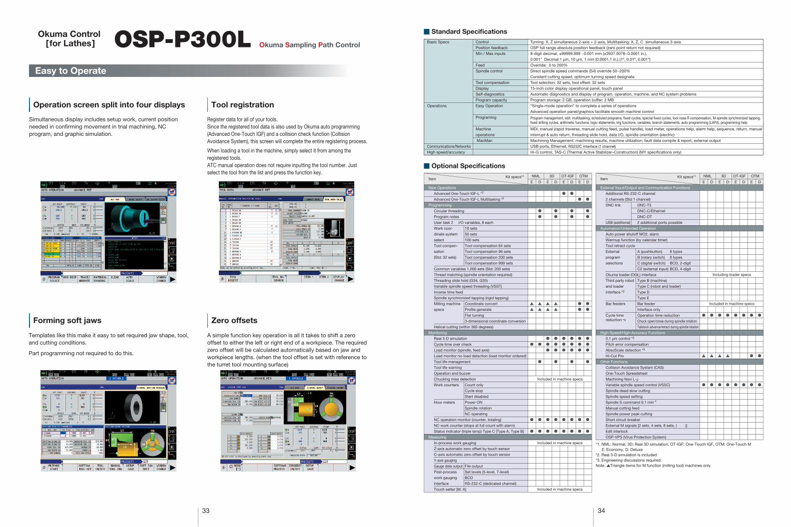
A simple function key operation is all it takes to shift a zero offset to either the left or right end of a workpiece. The required zero offset will be calculated automatically based on jaw and workpiece lengths. (when the tool offset is set with reference to the turret tool mounting surface)
Templates like this make it easy to set required jaw shape, tool, and cutting conditions.
Part programming not required to do this.
Easy to Operate
Operation screen split into four displays
Forming soft jaws Zero offsets
Simultaneous display includes setup work, current position needed in con�rming movement in trial machining, NC program, and graphic simulation.
Tool registration
Register data for all of your tools. Since the registered tool data is also used by Okuma auto programming (Advanced One-Touch IGF) and a collision check function (Collision Avoidance System), this screen will complete the entire registering process.
When loading a tool in the machine, simply select it from among the registered tools.ATC manual operation does not require inputting the tool number. Just select the tool from the list and press the function key.
Okuma Control [ for Lathes] Basic Specs
Operations
Communications/NetworksHigh speed/accuracy
ControlPosition feedbackMin / Max inputs
FeedSpindle control
Tool compensationDisplaySelf-diagnosticsProgram capacityEasy Operation
Programing
Machineoperations MacMan
Turning: X, Z simultaneous 2-axis + 2-axis, Multitasking: X, Z, C simultaneous 3-axisOSP full range absolute position feedback (zero point return not required)8-digit decimal, ±99999.999 ~0.001 mm (±3937.0078~0.0001 in.),0.001° Decimal:1 µm, 10 µm, 1 mm (0.0001,1 in.) (1º, 0.01º, 0.001º)Override: 0 to 200%Direct spindle speed commands (S4) override 50~200%Constant cutting speed, optimum turning speed designateTool selection: 32 sets, tool offset: 32 sets15-inch color display operational panel, touch panel Automatic diagnostics and display of program, operation, machine, and NC system problemsProgram storage: 2 GB, operation buffer: 2 MB“Single-mode operation” to complete a series of operationsAdvanced operation panel/graphics facilitate smooth machine control
Program management, edit, multitasking, scheduled programs, �xed cycles, special �xed cycles, tool nose R compensation, M-spindle synchronized tapping, �xed drilling cycles, arithmetic functions, logic statements, trig functions, variables, branch statements, auto programming (LAP4), programming help
MDI, manual (rapid traverse, manual cutting feed, pulse handle), load meter, operations help, alarm help, sequence, return, manualinterrupt & auto return, threading slide hold, data I/O, spindle orientation (electric)Machining Management: machining results, machine utilization, fault data compile & report, external outputUSB ports, Ethernet, RS232C interface (1 channel)
Hi-G control, TAS-C (Thermal Active Stabilizer–Construction) (MY speci�cations only)
■ Standard Specifications
■ Optional Specifications
*1. NML: Normal, 3D: Real 3D simulation, OT-IGF: One-Touch IGF, OTM: One-Touch ME: Economy, D: Deluxe
*2. Real 3-D simulation is included*3. Engineering discussions required.Note. ▲Triangle items for M function (milling tool) machines only.
New Operations
Advanced One-Touch IGF-L *2
Advanced One-Touch IGF-L Multitasking *2
Programming
Circular threading
Program notes
User task 2 I/O variables, 8 each
Work coor- 10 sets
dinate system 50 sets
select 100 sets
Tool compen- Tool compensation 64 sets
sation Tool compensation 96 sets
(Std: 32 sets) Tool compensation 200 sets
Tool compensation 999 sets
Common variables 1,000 sets (Std: 200 sets)
Thread matching (spindle orientation required)
Threading slide hold (G34, G35)
Variable spindle speed threading (VSST)
Inverse time feed
Spindle synchronized tapping (rigid tapping)
Milling machine Coordinate convert
specs Pro�le generate
Flat turning
3-dimensional coordinate conversion
Helical cutting (within 360 degrees)
Monitoring
Real 3-D simulation
Cycle time over check
Load monitor (spindle, feed axis)
Load monitor no-load detection (load monitor ordered)
Tool life management
Tool life warning
Operation end buzzer
Chucking miss detection
Work counters Count only
Cycle stop
Start disabled
Hour meters Power ON
Spindle rotation
NC operating
NC operation monitor (counter, totaling)
NC work counter (stops at full count with alarm)
Status indicator (triple lamp) Type C [Type A, Type B]
Measuring
In-process work gauging
Z-axis automatic zero offset by touch sensor
C-axis automatic zero offset by touch sensor
Y-axis gauging
Gauge data output File output
Post-process Set levels (5-level, 7-level)
work gauging BCD
interface RS-232-C (dedicated channel)
Touch setter [M, A]
E D E D E D
NML 3D OT-IGF
E D
OTM
Included in machine specs
Included in machine specs
Included in machine specs
External Input/Output and Communication Functions
Additional RS-232-C channel
2 channels (Std 1 channel)
DNC link DNC-T3
DNC-C/Ethernet
DNC-DT
USB (additional) 2 additional ports possible
Automation/Untended Operation
Auto power shutoff MO2, alarm
Warmup function (by calendar timer)
Tool retract cycle
External A (pushbutton) 8 types
program B (rotary switch) 8 types
selections C (digital switch) BCD, 2-digit
C2 (external input) BCD, 4-digit
Okuma loader (OGL) interface
Third party robot Type B (machine)
and loader Type C (robot and loader)
interface *3 Type D
Type E
Bar feeders Bar feeder
Interface only
Cycle time Operation time reductionreduction *3 Chuck open/close during spindle rotation
Tailstock advance/retract during spindle lotation
High-Speed/High-Accuracy Functions
0.1 µm control *3
Pitch error compensation
AbsoScale detection *3
Hi-Cut Pro
Other Functions
Collision Avoidance System (CAS)
One-Touch Spreadsheet
Machining Navi L-g
Variable spindle speed control (VSSC)
Spindle dead-slow cutting
Spindle speed setting
Spindle S command 0.1 min-1
Manual cutting feed
Spindle power peak cutting
Short circuit breaker
External M signals [2 sets, 4 sets, 8 sets, ( )]
Edit interlock
OSP-VPS (Virus Protection System)
DE D E D E
Included in machine specs
Including loader specs
NML 3D OT-IGF
DE
OTMItem Kit specs*1 Kit specs*1
Item
▲
▲
●
●
●
●
●
▲
▲
●
●
●
●
▲
▲
●
●
●
●
●
●
●
▲
▲
●
●
●
●
●
●
●
●
●
●
●
●
●
●
●
●
●
●
●
●
●
●
●
●
●
●
●
●
●
●
●
●
●
●
●
●
●
●
●
●
●
●
●
▲
●
●
▲
●
●
▲
●
●
▲
●
●
●
●
●
●
●
●
●
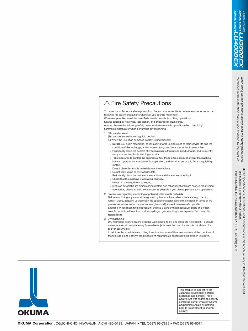
This product is subject to the Japanese government Foreign Exchange and Foreign Trade Control Act with regard to security controlled items; whereby Okuma Corporation should be noti�ed prior to its shipment to another country.
, OGUCHI-CHO, NIWA-GUN, AICHI 480-0193, JAPAN • TEL (0587) 95-7825 • FAX (0587) 95-6074
To protect your factory and equipment from �re and assure continued safe operation, observe the following �re safety precautions whenever you operate machinery. Whenever possible, avoid the use of oil-based coolants for cutting operations. Sparks caused by hot chips, tool friction, and grinding can cause �res. Always observe the following safety measures to ensure safe operation when machining �ammable materials or when performing dry machining.
Before machining any material designated by law as a �ammable substance, e.g., plastic, rubber, wood, acquaint yourself with the special characteristics of the material in terms of �re prevention, and observe the precautions given in (2) above to ensure safe operation. Example: When machining magnesium, there is a danger that magnesium chips and water-soluble coolants will react to produce hydrogen gas, resulting in an explosive �re if any chip should ignite.
Dry machining is a �re hazard because workpieces, tools, and chips are not cooled. To ensure safe operation, do not place any �ammable objects near the machine and do not allow chips to over accumulate. In addition, be sure to check cutting tools to make sure of their service life and the condition of the tool edge, and observe the precautions regarding oil-based coolants given in (2) above.
(1) Use nonflammable cutting fluid coolant. (2) When the use of an oil-based coolant is unavoidable:
Before you begin machining, check cutting tools to make sure of their service life and the condition of the tool edge, and choose cutting conditions that will not cause a �re. Periodically clean the coolant �lter to maintain suf�cient coolant discharge, and frequently verify that coolant is discharging normally. Take measures to control the outbreak of �re: Place a �re extinguisher near the machine, have an operator constantly monitor operation, and install an automatic �re extinguishing system. Do not place �ammable materials near the machine.Do not allow chips to over accumulate. Periodically clean the inside of the machine and the area surrounding it.Check that the machine is operating normally. Never run the machine unattended. Since an automatic �re extinguishing system and other peripherals are needed for grinding operations, please let us know as soon as possible if you plan to perform such operations.
Fire Safety Precautions
1. Oil-based coolant
2. Precautions regarding machining of potentially flammable materials
3. Dry machining
•
•
•
•
•
•
•
•
•
When using O
kuma p
roducts, alw
ays read the safety p
recautionsm
entioned in the instruction m
anual and attached
to the prod
uct.
� The sp
eci�cations, illustrations, and d
escriptions in this b
rochure vary in different m
arkets and
are subject to change w
ithout notice.P
ub N
o.SIM
UL TU
RN
LU3000/4000 E
X-E
-(1a)-400-(Aug 2014)
2-Sad
dle C
NC
Lathe