Embed Size (px)
Citation preview
2-Photon Polymerization for
Laser Direct-Write Target Fabrication*
O. Stein, N. Petta
Schafer CorporationYing Liu, Lijia Jiang, Yongfeng Lu
University of Nebraska, Lincoln
*Work Supported under DOE contract No:
DE-NA0001430
Outline:
• Introduction- 2 photon polymerization process
• The hardware
• Motivation- Schafer’s developmental effort
• Target fabrication for NRL
• Experimental conditions and characterization
• Future outlook
Schafer 2PP effort started in 2011 and subsequently
launched collaborations with universities and DOE Labs:
• Initial work (2011-2014) focused on demonstrating 2PP as a possible
means to make:
o Fill tubes (UC Berkeley- Bernat et al. FS&T 70(2) Aug 2016)
o Foam-like structures complex surface shapes (with UNL)
• Jiang et al. FS&T 70(2) Aug 2016
• Jiang et al. ICALEO proc. 2015
• Jiang et al. MRS Bulletin 41 (2016) 975
• Our initial work led to a number of follow-on collaborations:
o LLNL in support of foam targets (UNL, Park, Biener, Oakdale)
o LLE custom target support structures (Harding et al.)
o LANL- Nanoscribe training at UNL, joint characterization of parts etc.
(Oertel, Munchehausen, Patterson, Herman, Grote)
• Our colleagues at LLNL recently published on UV post treatment to improve
mechanical properties (Oakdale et al. Opt. Exp. 24, 24 Nov 2016 27077)

Photo- Induced Polymerization
C. LaFratta et al., Angew. Chem. Int. Ed. 2007, 46, 6238 – 6258
Hg Lamp Ti: Sapphire
• The process involving the absorption of two photons scales as I2
(where I is the laser intensity)
• Low average power and in wavelengthsfar from absorption prevent
single photon process
Typical voxel :
a/b ~2.5 (a~1000nm, b~400nm)
Threshold
𝒅𝑰 𝒛
𝒅𝒛= − 𝛽𝑰 𝒛 2
𝒅𝑰 𝒛
𝒅𝒛= −𝑰 𝒛 − 𝛽𝑰 𝒛 2
0
2-photon absorption
𝒅𝑰 𝒛
𝒅𝒛= −𝑰 𝒛
Beer-Lambert law
α, absorption coefficient.
One photon absorption

Cut-away side view (highly schematic)
* Collaboration with Prof Yongfeng Lu’s group at Univ. of Neb
• Relatively high scan
velocity
• High resolution
scanning
in low area
• Proprietary resins
• Vast stitching defects.
200μm 30μm
Stitch defect
Currently we are printing structures using a commercial
2PP system: Nanoscribe Photonics GT
Although accessible, this machine isn’t optimized for R&D and target fabrication

• Laser direct write can serve as a complementary process to conventional
sol-gel process for low density material (LDM) synthesis
• Complex architectures can be realized in micron scale
• Short turnover time form CAD model design to fabrication
In 2011 Schafer’s effort began through collaborations with Universities
Fill tube1 Fill tube+support2,3 Low density Material AM-FOAM FY16 shot on OMEGA2
0.2g/cc1 prof. Costas Grigoropoulos, Mechanical Engineering, UC Berkeley2 prof. Yongfeng Lu, Electrical and Computer Engineering UN, Lincoln3 University of Rochester, LLE
A B0.4mm
2.0mm
1.5mm
The Motivation: 2PP could serve as an efficient tool to
directly print complex structures
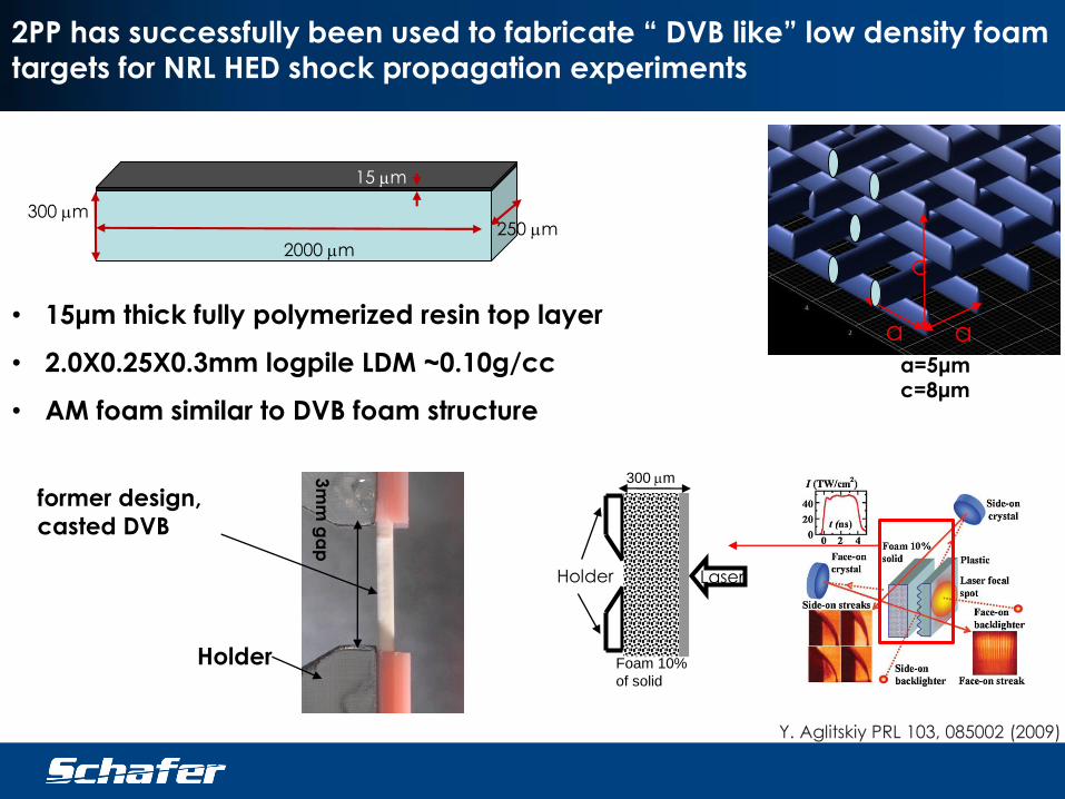
300 mm250 mm
2000 mm
15 mm
aa
c
• 15μm thick fully polymerized resin top layer
• 2.0X0.25X0.3mm logpile LDM ~0.10g/cc
• AM foam similar to DVB foam structure
Y. Aglitskiy PRL 103, 085002 (2009)
Laser
300 mm
Foam 10%
of solid
Holder
former design,
casted DVB
Holder
a=5μmc=8μm
3m
m g
ap
2PP has successfully been used to fabricate “ DVB like” low density foam
targets for NRL HED shock propagation experiments
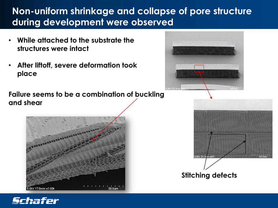
• While attached to the substrate the
structures were intact
• After liftoff, severe deformation took
place
Stitching defects
Non-uniform shrinkage and collapse of pore structure
during development were observed
Failure seems to be a combination of buckling
and shear

• Our logpile design consists of a typical
pore size of d=4-5μm
• The applied pressure due to solvent evaporation
is estimated as ~1.4psi
• Compared to the mechanical properties
of the resin these forces are low and practically negligible
At pore sizes of 4-5 microns we would not expect Capillary
forces to play a role and were calculated to be negligible
d
𝑃 = 2𝛿 ∙ 𝑐𝑜𝑠 𝜃 /𝑑
for typical rinsing fluid θ->0˚
δIPA=23mN·m-1
50μm

A
40μm
C
20μ
m
D
20μm
A,C- Air
Dried
40μm
B
B, D- Supercritically
dried
CAD model of the structure
Drying method have an
extensive effect on the
structural integrity outcome.
The effect of solvent removal
made us reconsider the
effect of capillary forces.
The effect of super-critical point drying

We took a closer look at causes of capillary forces
8μm
700nm
Under higher magnification SEM nanometer
sized cracks are evident throughout the
structure
Estimating the capillary pressure according to
the pore dimension gives a conservative
value of
~65psi
Cracks indicate imperfect polymerization
during illumination and
stage scanning.
Jiang et al. Opt. Lett. (2014) 39 3034
𝐷. 𝐶. = 1 −
𝑃𝐶=𝐶𝑃𝐶=𝑂
𝑀𝐶=𝐶
𝑀𝐶=𝑂
𝑋100

600μm
1μm
A
C
700nm
B
UV cured
UV cured2PP
• A drop of resin was UV cured and imaged
with SEM. Image A
• Most of the areas look crack free either on
the surface of the sample or within its
volume. Image C
• Polymerization via 2 photon absorption of
the same resin reveals high density of
cracks. Image B.
UV Cured resin is fully polymerized with no cracks

Low density structure bowing- 2nd type of
deformation
• All of the structures containing a top fully densified layer buckle
to some extent
• Low density structures without top layer retain their form
Side View, taken on a laser confocal microscope Fully densified layer, 15μm thick.
uniform linear Shrinkage of 7.5% occurs during the development process
1.86mm (2.0)
1.85mm (2.0)
1.76mm (2.0)
1.92mm (2.0)B
A
Perspective view
0.25mm
0.3mm
2.0mm
0.015mm
stitching defects
0.25mm
0.3mm
2.0mm
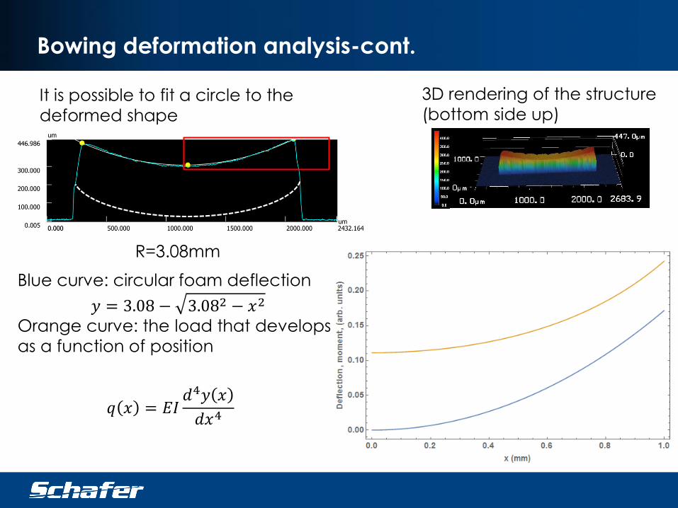
3D rendering of the structure
(bottom side up)It is possible to fit a circle to the
deformed shape
R=3.08mm
Blue curve: circular foam deflection
𝑦 = 3.08 − 3.082 − 𝑥2
Orange curve: the load that develops
as a function of position
Bowing deformation analysis-cont.
𝑞 𝑥 = 𝐸𝐼𝑑4𝑦 𝑥
𝑑𝑥4
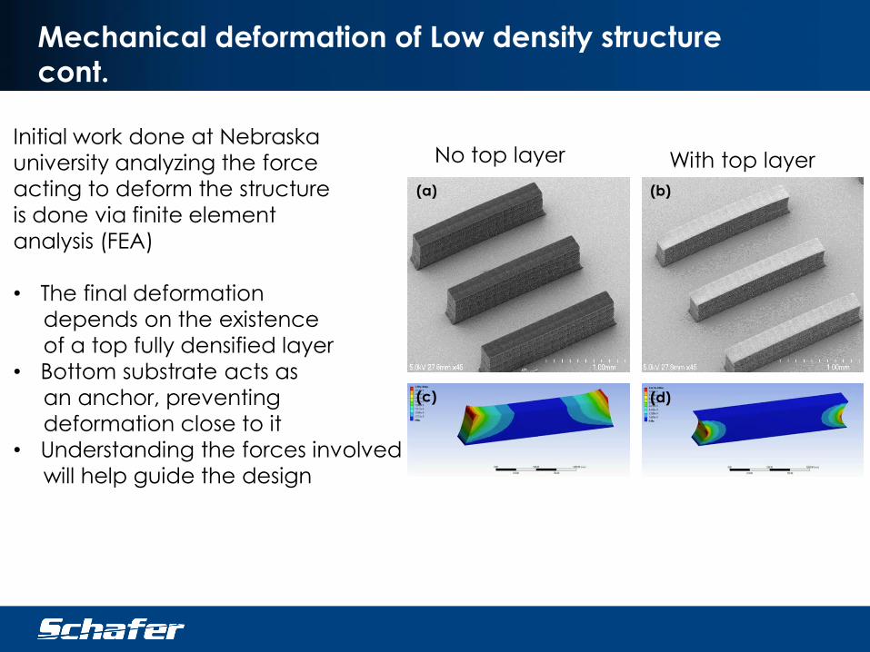
(a) (b)
(c) (d)
Mechanical deformation of Low density structure
cont.
No top layer With top layerInitial work done at Nebraska
university analyzing the force
acting to deform the structure
is done via finite element
analysis (FEA)
• The final deformation
depends on the existence
of a top fully densified layer
• Bottom substrate acts as
an anchor, preventing
deformation close to it
• Understanding the forces involved
will help guide the design
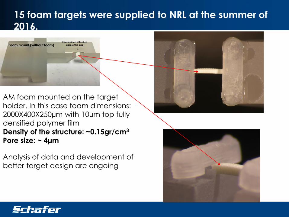
AM foam mounted on the target
holder. In this case foam dimensions:
2000X400X250µm with 10µm top fully
densified polymer film
Density of the structure: ~0.15gr/cm3
Pore size: ~ 4μm
15 foam targets were supplied to NRL at the summer of
2016.
Analysis of data and development of
better target design are ongoing
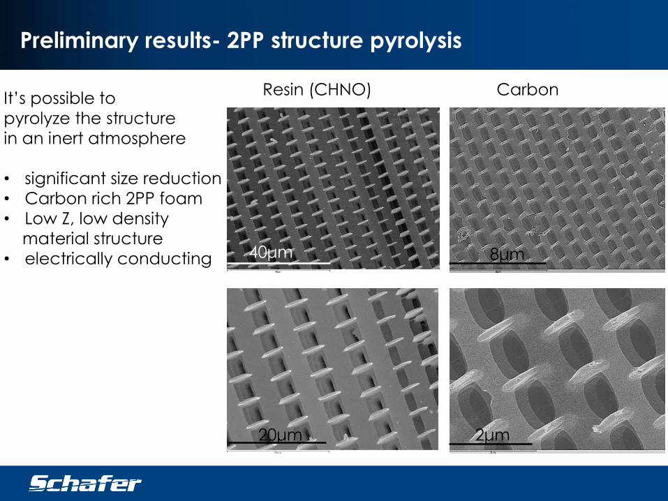
Preliminary results- 2PP structure pyrolysis
8μm40μm
2μm20μm
It’s possible to
pyrolyze the structure
in an inert atmosphere
• significant size reduction
• Carbon rich 2PP foam
• Low Z, low density
material structure
• electrically conducting
Resin (CHNO) Carbon
Summary
• 15 Additive Manufacturing foam targets were supplied to
NRL to be shot on Nike laser (original shot date was in late 2016)
• Super-critical drying was proven to be crucial in preserving the
foam’s internal structure
• analysis of foam bending is performed via FEA
• Additional designs are constantly examined in order to reduce
global deformation of the target
• Demonstration of 2PP structure carbonization lifted off the
substrate
Acknowledgements
• Ying Liu, Jack Campbell, Lijia
Jiang, Yongfeng Lu
• Yefim Aglitskiy
• Tom Bernat, Jared Hund, Jon
Streit
• Brian Patterson
• David Harding

Additional slides
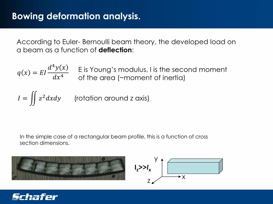
Bowing deformation analysis.
According to Euler- Bernoulli beam theory, the developed load on
a beam as a function of deflection:
𝑞 𝑥 = 𝐸𝐼𝑑4𝑦 𝑥
𝑑𝑥4E is Young’s modulus, I is the second moment
of the area (~moment of inertia)
𝐼 = 𝑧2𝑑𝑥𝑑𝑦 (rotation around z axis)
In the simple case of a rectangular beam profile, this is a function of cross section dimensions.
x
y
z
Iz>>Ix
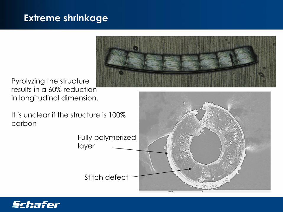
Extreme shrinkage
Pyrolyzing the structure
results in a 60% reduction
in longitudinal dimension.
It is unclear if the structure is 100%
carbon
Stitch defect
Fully polymerized
layer
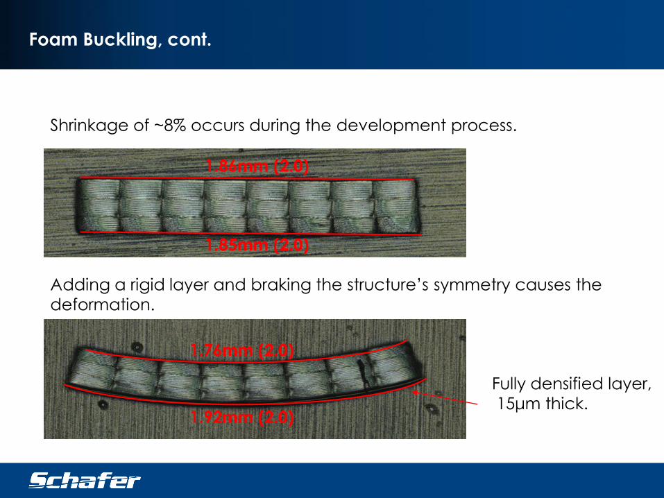
Foam Buckling, cont.
Shrinkage of ~8% occurs during the development process.
1.86mm (2.0)
1.85mm (2.0)
Adding a rigid layer and braking the structure’s symmetry causes the
deformation.
1.76mm (2.0)
1.92mm (2.0)
Fully densified layer,
15μm thick.
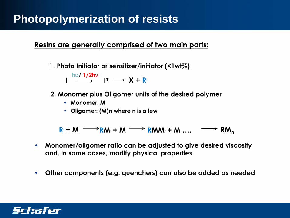
Photopolymerization of resists
Resins are generally comprised of two main parts:
1. Photo Initiator or sensitizer/initiator (<1wt%)
2. Monomer plus Oligomer units of the desired polymer
• Monomer: M
• Oligomer: (M)n where n is a few
• Monomer/oligomer ratio can be adjusted to give desired viscosity
and, in some cases, modify physical properties
• Other components (e.g. quenchers) can also be added as needed
Ihυ/ 1/2hn
X + R.
R. + M RM. + M RMM. + M …. RMn
I*


![Crystals OPEN ACCESS crystals - Semantic Scholar · Crystals 2015, 5 63 called direct laser writing [24–26]. This method is based on the nonlinear two-photon polymerization of a](https://img.pdfslide.us/doc/110x75/5fb5edc684c3ef5de1372ffd/crystals-open-access-crystals-semantic-scholar-crystals-2015-5-63-called-direct.jpg)