Embed Size (px)
DESCRIPTION
Huawei bts manual
Citation preview

www.huawei.com
Copyright © 2008 Huawei Technologies Co., Ltd. All rights reserved.
OptiX OSN 1500/2500/3500/7500/9500 Equipment Commissioning
PDF created with pdfFactory Pro trial version www.pdffactory.com
Copyright © 2008 Huawei Technologies Co., Ltd. All rights reserved. Page1
Objectives
l Upon completion of this course, you will be able to:
p Successfully complete hardware and software commissioning of
OptiX OSN 1500/2500/3500/7500/9500 equipment
p Interconnect all the equipment and perform system commissioning
PDF created with pdfFactory Pro trial version www.pdffactory.com
Copyright © 2008 Huawei Technologies Co., Ltd. All rights reserved. Page2
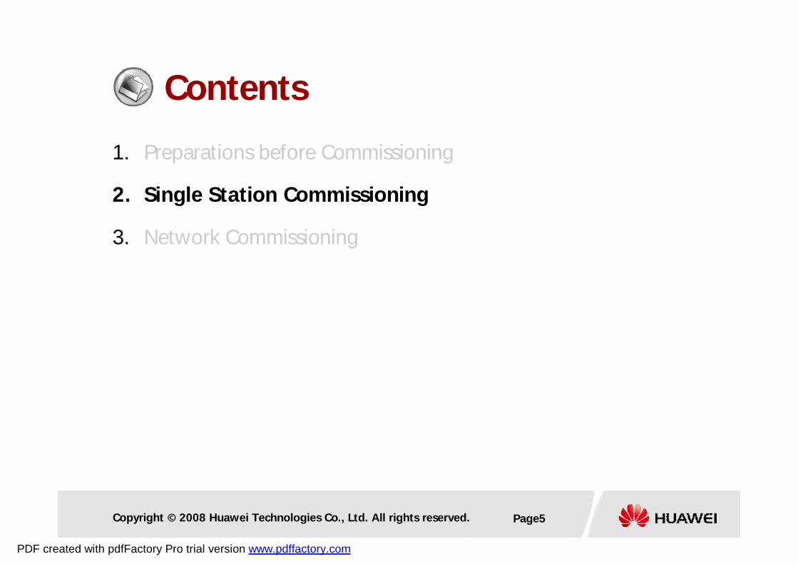
Contents
1. Preparations before Commissioning
2. Single Station Commissioning
3. Network Commissioning
PDF created with pdfFactory Pro trial version www.pdffactory.com
Copyright © 2008 Huawei Technologies Co., Ltd. All rights reserved. Page3
Preparations
l Requirements to Commissioning Engineers
p Be familiar with the fundamentals of SDH, PDH, Ethernet, and
ATM
p Be familiar with the OptiX OSN equipment
p Be familiar with the T2000,T2000LCT
p Skillful with test instruments
PDF created with pdfFactory Pro trial version www.pdffactory.com
Copyright © 2008 Huawei Technologies Co., Ltd. All rights reserved. Page4
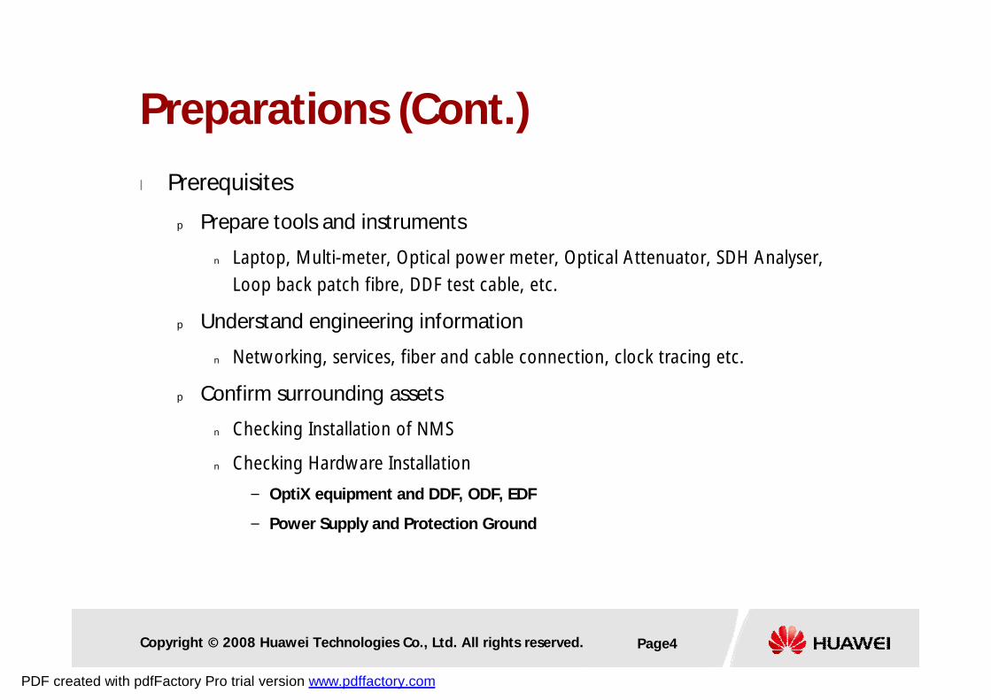
Preparations (Cont.)
l Prerequisites
p Prepare tools and instruments
n Laptop, Multi-meter, Optical power meter, Optical Attenuator, SDH Analyser,
Loop back patch fibre, DDF test cable, etc.
p Understand engineering information
n Networking, services, fiber and cable connection, clock tracing etc.
p Confirm surrounding assets
n Checking Installation of NMS
n Checking Hardware Installation
– OptiX equipment and DDF, ODF, EDF
– Power Supply and Protection Ground
PDF created with pdfFactory Pro trial version www.pdffactory.com
Copyright © 2008 Huawei Technologies Co., Ltd. All rights reserved. Page5
Contents
1. Preparations before Commissioning
2. Single Station Commissioning
3. Network Commissioning
PDF created with pdfFactory Pro trial version www.pdffactory.com
Copyright © 2008 Huawei Technologies Co., Ltd. All rights reserved. Page6
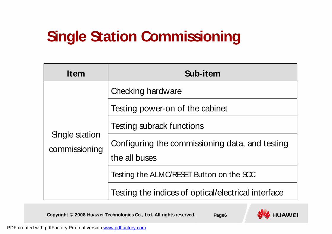
Single Station Commissioning
Item Sub-item
Single station
commissioning
Checking hardware
Testing power-on of the cabinet
Testing subrack functions
Configuring the commissioning data, and testing
the all buses
Testing the ALMC/RESET Button on the SCC
Testing the indices of optical/electrical interface
PDF created with pdfFactory Pro trial version www.pdffactory.com
Copyright © 2008 Huawei Technologies Co., Ltd. All rights reserved. Page7
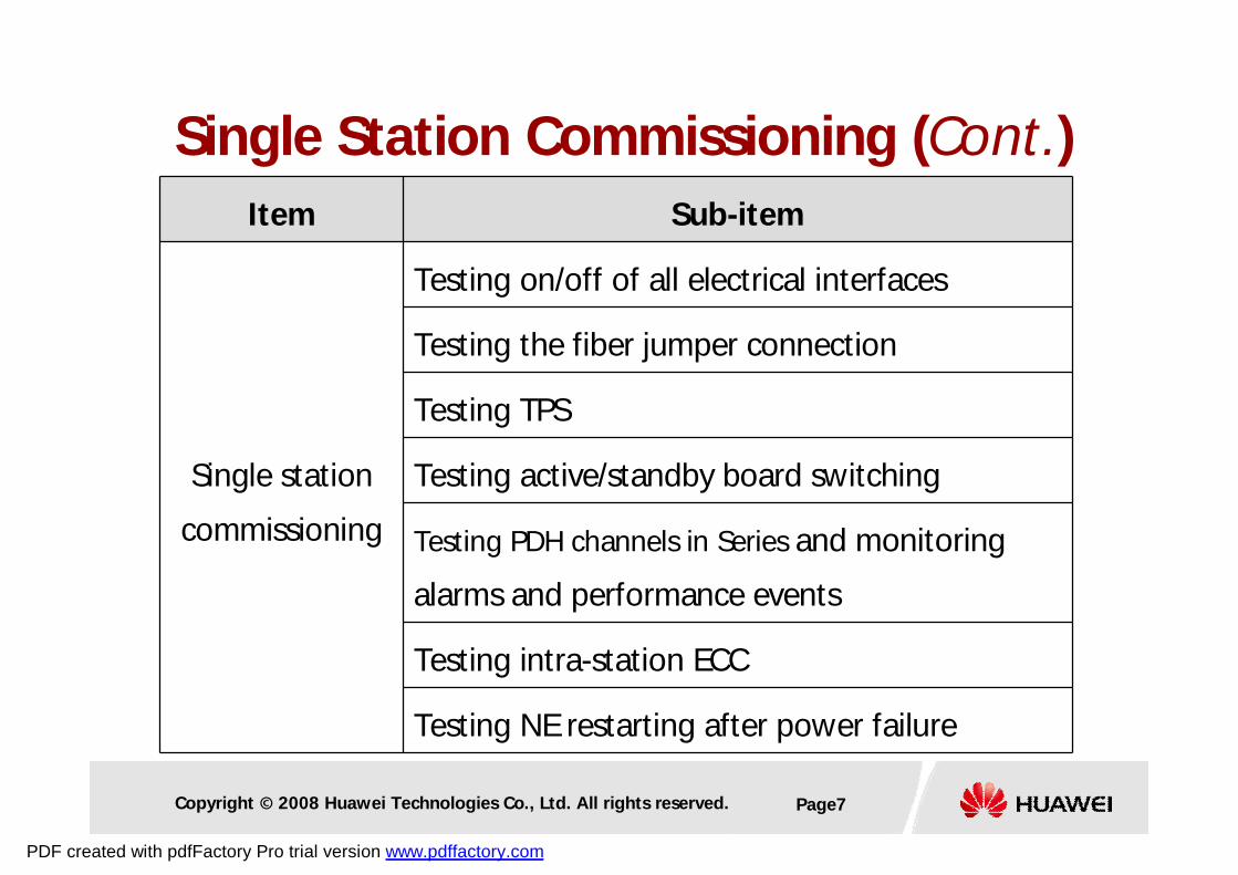
Single Station Commissioning (Cont.)Item Sub-item
Single station
commissioning
Testing on/off of all electrical interfaces
Testing the fiber jumper connection
Testing TPS
Testing active/standby board switching
Testing PDH channels in Series and monitoring
alarms and performance events
Testing intra-station ECC
Testing NE restarting after power failure
PDF created with pdfFactory Pro trial version www.pdffactory.com
Copyright © 2008 Huawei Technologies Co., Ltd. All rights reserved. Page8
Checking Hardware (Cont.)
l Checking cabinet
p Installation of cabinets must comply with the requirements of the
construction drawing
p Multiple cabinets must be aligned, leveled and firmly fixed
p All cabinets must be labelled
p Power supply cables must be correctly connected (RTN+, NEG-)
p Ground cable must be correctly connected to the Ground stud
p Ground wires to the door must also be well connected
p The Orderwire phone and ESD wrist strap are in place
p No unrelated materials inside
PDF created with pdfFactory Pro trial version www.pdffactory.com
Copyright © 2008 Huawei Technologies Co., Ltd. All rights reserved. Page9
Checking Hardware (Cont.)
l Checking sub-rack
p Power supply cables must be correctly connected to the right
connectors (PIU 1, PIU 2)
p Ground wires to the sub-rack must be well connected
p The vacant slots are installed with blank panels
p Confirm available boards
PDF created with pdfFactory Pro trial version www.pdffactory.com
Copyright © 2008 Huawei Technologies Co., Ltd. All rights reserved. Page10
Checking Hardware (Cont.)
l Checking cables
p Ethernet cable, PDH cables
p Optical fibers, STM-1e cables
p Network clock synchronization cables
ü Cables are connected, bundled and arranged neatly
ü All cables must be correctly labeled
ü The power cables and grounding cables outside the cabinet are
arranged separately from the signal cables
PDF created with pdfFactory Pro trial version www.pdffactory.com
Copyright © 2008 Huawei Technologies Co., Ltd. All rights reserved. Page11
Checking Hardware (Cont.)
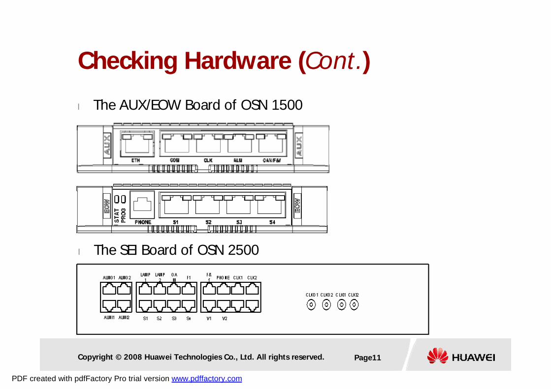
l The AUX/EOW Board of OSN 1500
l The SEI Board of OSN 2500
PDF created with pdfFactory Pro trial version www.pdffactory.com
Copyright © 2008 Huawei Technologies Co., Ltd. All rights reserved. Page12
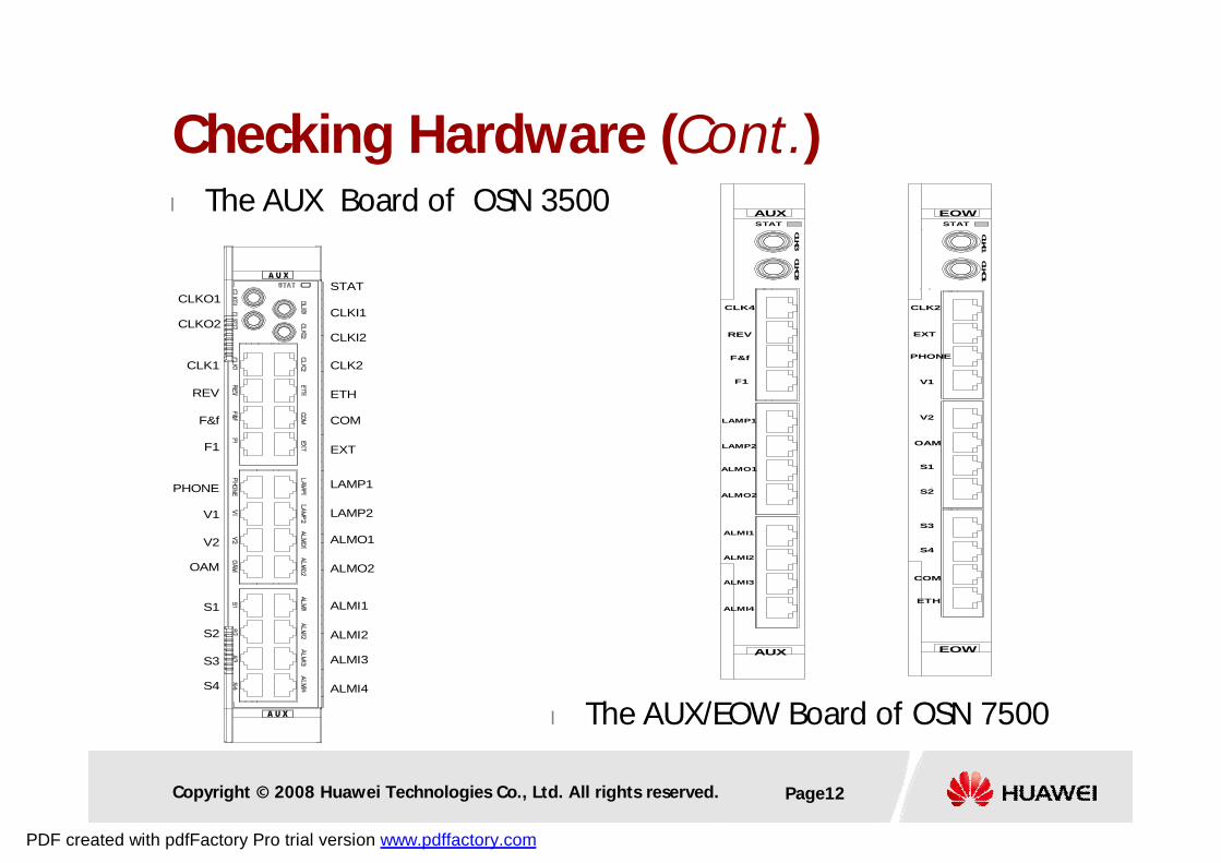
Checking Hardware (Cont.)l The AUX Board of OSN 3500
CLKI1
CLKI2
CLKO1
CLKO2
CLK2
ETH
COM
EXT
LAMP1
LAMP2
ALMO1
ALMO2
ALMI1
ALMI2
ALMI3
ALMI4
CLK1
REV
F&f
PHONE
V1
V2
OAM
S1
S2
S3
S4
F1
STAT
CLK
I3CLK
O3
CLK4
REV
F&f
F1
ALMI1
ALMI2
ALMI3
ALMI4
STAT
LAMP1
LAMP2
ALMO1
ALMO2
AUX
AUX
STAT
CLK2
ETH
COM
EXT
PHONE
V1
V2
OAM
S1
S2
S3
S4
EOW
EOW
CLK
I1CLK
O1
l The AUX/EOW Board of OSN 7500
PDF created with pdfFactory Pro trial version www.pdffactory.com
Copyright © 2008 Huawei Technologies Co., Ltd. All rights reserved. Page13
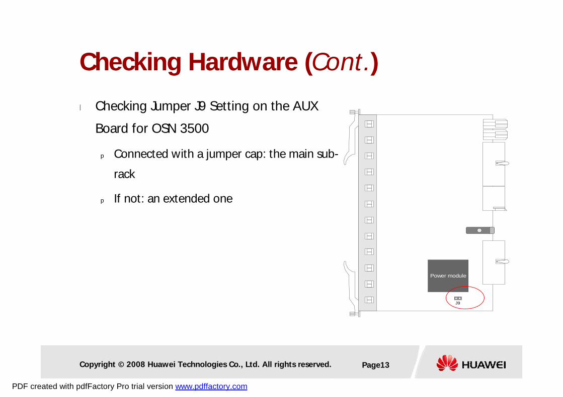
Checking Hardware (Cont.)
Power module
J9
l Checking Jumper J9 Setting on the AUX
Board for OSN 3500
p Connected with a jumper cap: the main sub-
rack
p If not: an extended one
PDF created with pdfFactory Pro trial version www.pdffactory.com
Copyright © 2008 Huawei Technologies Co., Ltd. All rights reserved. Page14
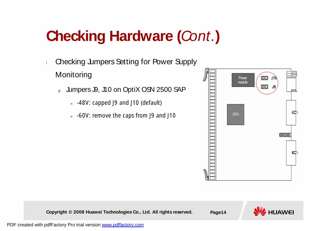
Checking Hardware (Cont.)
l Checking Jumpers Setting for Power Supply
Monitoring
p Jumpers J9, J10 on OptiX OSN 2500 SAP
n -48V: capped J9 and J10 (default)
n -60V: remove the caps from J9 and J10
PDF created with pdfFactory Pro trial version www.pdffactory.com
Copyright © 2008 Huawei Technologies Co., Ltd. All rights reserved. Page15
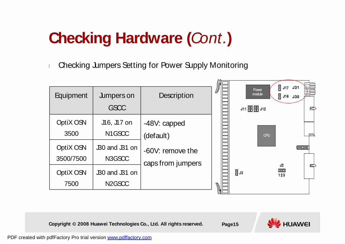
Checking Hardware (Cont.)
l Checking Jumpers Setting for Power Supply Monitoring
Equipment Jumpers on
GSCC
Description
OptiX OSN
3500
J16, J17 on
N1GSCC
-48V: capped
(default)
-60V: remove the
caps from jumpers
OptiX OSN
3500/7500
J30 and J31 on
N3GSCC
OptiX OSN
7500
J30 and J31 on
N2GSCC
PDF created with pdfFactory Pro trial version www.pdffactory.com
Copyright © 2008 Huawei Technologies Co., Ltd. All rights reserved. Page16
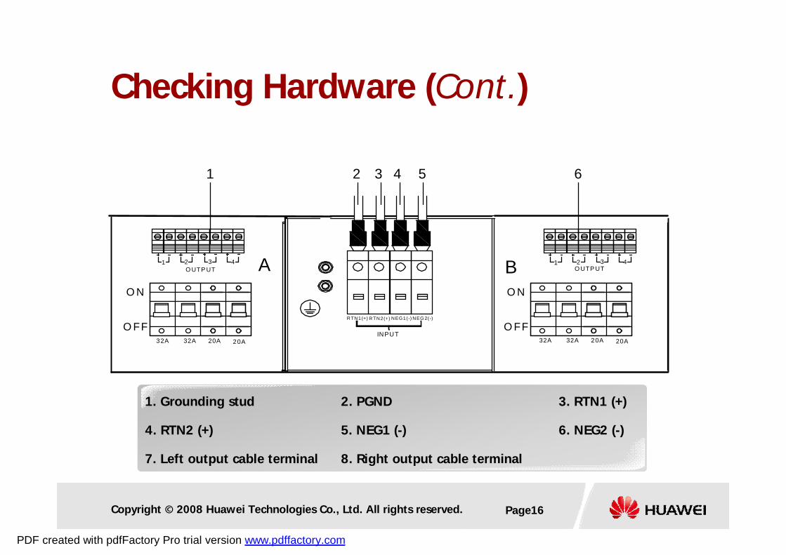
NEG 2(-)
INPUT
RTN2(+)RTN1(+) NEG1(-)
2 3 4 5
O N
O FF20A32A 32A 20A
O N
O FF
1 2 3 4
1 6
1 2 3 4
20A32A 32A 20A
O UTP UT O UTP UTA B
1. Grounding stud 2. PGND 3. RTN1 (+)
4. RTN2 (+) 5. NEG1 (-) 6. NEG2 (-)
7. Left output cable terminal 8. Right output cable terminal
Checking Hardware (Cont.)
PDF created with pdfFactory Pro trial version www.pdffactory.com
Copyright © 2008 Huawei Technologies Co., Ltd. All rights reserved. Page17
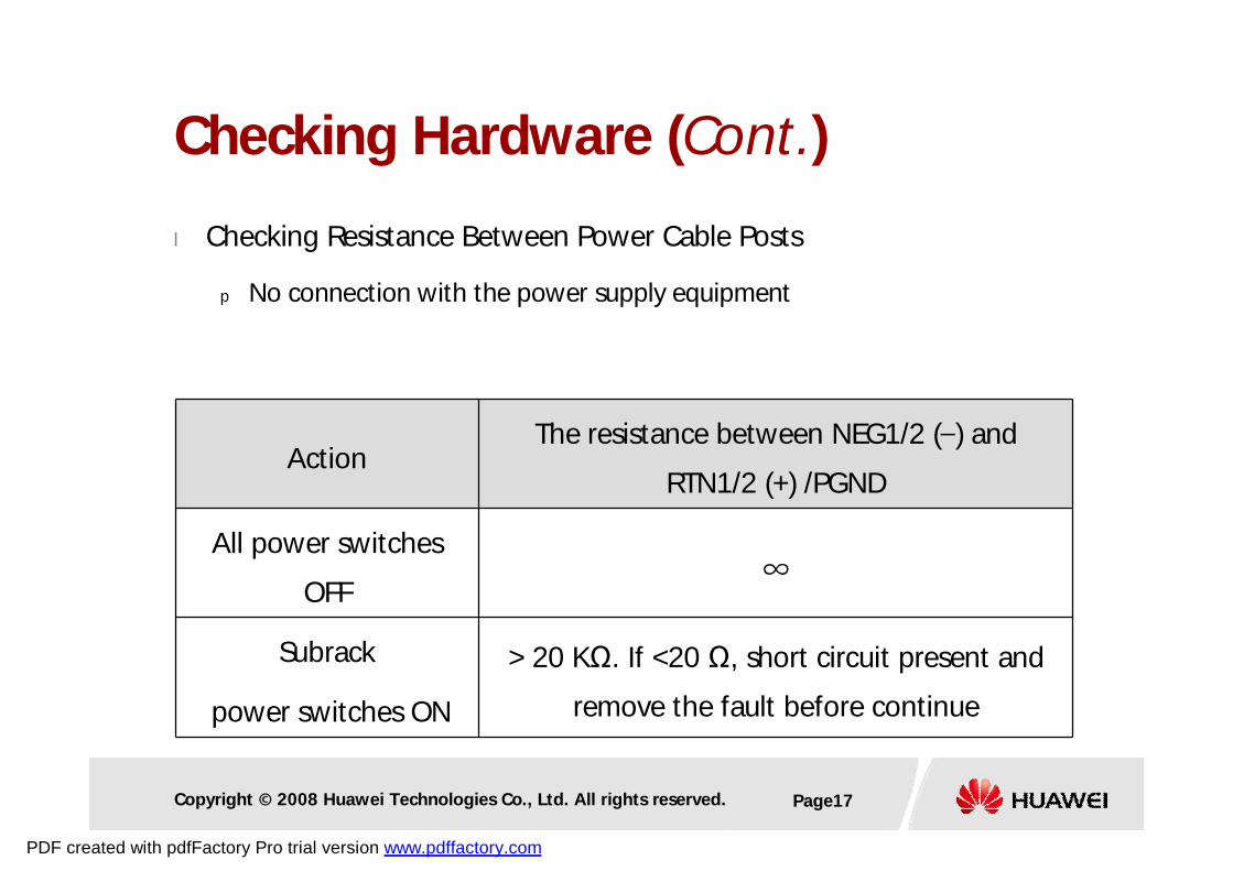
l Checking Resistance Between Power Cable Posts
p No connection with the power supply equipment
ActionThe resistance between NEG1/2 (–) and
RTN1/2 (+) /PGND
All power switches
OFF∞
Subrack
power switches ON
> 20 KΩ. If <20 Ω, short circuit present and
remove the fault before continue
Checking Hardware (Cont.)
PDF created with pdfFactory Pro trial version www.pdffactory.com
Copyright © 2008 Huawei Technologies Co., Ltd. All rights reserved. Page18
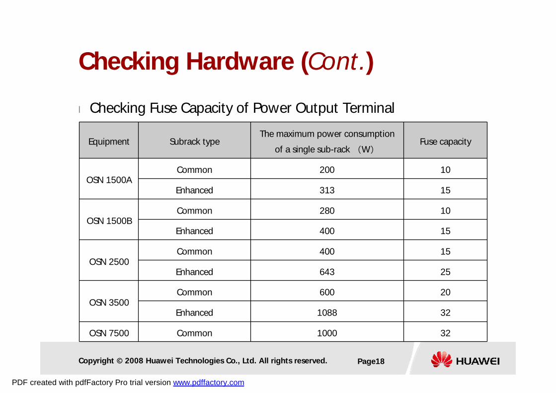
l Checking Fuse Capacity of Power Output Terminal
Equipment Subrack typeThe maximum power consumption
of a single sub-rack (W)Fuse capacity
OSN 1500ACommon 200 10
Enhanced 313 15
OSN 1500BCommon 280 10
Enhanced 400 15
OSN 2500Common 400 15
Enhanced 643 25
OSN 3500Common 600 20
Enhanced 1088 32
OSN 7500 Common 1000 32
Checking Hardware (Cont.)
PDF created with pdfFactory Pro trial version www.pdffactory.com
Copyright © 2008 Huawei Technologies Co., Ltd. All rights reserved. Page19
l Testing method
pConnect OSN equipment to the power equipment
n Ensure that the positive and negative poles are not connected reversely
p Measure the voltage of the power supply equipment at the top of the
cabinet
n Ranging from –38.4 V to –57.6 V (-48V±20%)
n Ranging from –48 V to –72 V (-60V±20%)
Testing Power-on of the Cabinet
PDF created with pdfFactory Pro trial version www.pdffactory.com
Copyright © 2008 Huawei Technologies Co., Ltd. All rights reserved. Page20
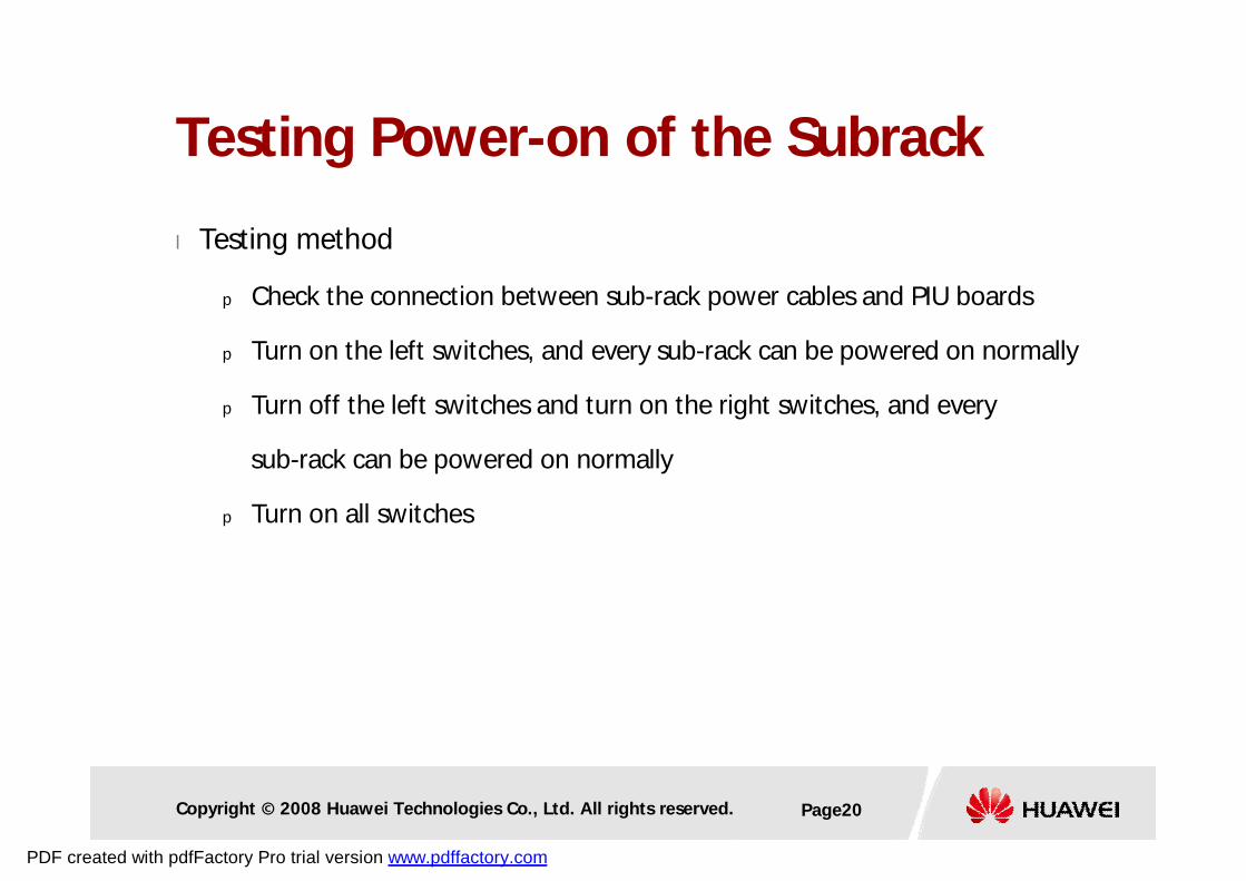
l Testing method
p Check the connection between sub-rack power cables and PIU boards
p Turn on the left switches, and every sub-rack can be powered on normally
p Turn off the left switches and turn on the right switches, and every
sub-rack can be powered on normally
p Turn on all switches
Testing Power-on of the Subrack
PDF created with pdfFactory Pro trial version www.pdffactory.com
Copyright © 2008 Huawei Technologies Co., Ltd. All rights reserved. Page21
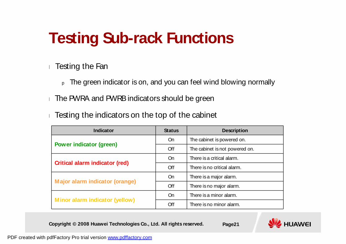
Indicator Status Description
Power indicator (green)On The cabinet is powered on.
Off The cabinet is not powered on.
Critical alarm indicator (red)On There is a critical alarm.
Off There is no critical alarm.
Major alarm indicator (orange)On There is a major alarm.
Off There is no major alarm.
Minor alarm indicator (yellow)On There is a minor alarm.
Off There is no minor alarm.
Testing Sub-rack Functions
l Testing the Fan
p The green indicator is on, and you can feel wind blowing normally
l The PWRA and PWRB indicators should be green
l Testing the indicators on the top of the cabinet
PDF created with pdfFactory Pro trial version www.pdffactory.com
Copyright © 2008 Huawei Technologies Co., Ltd. All rights reserved. Page22
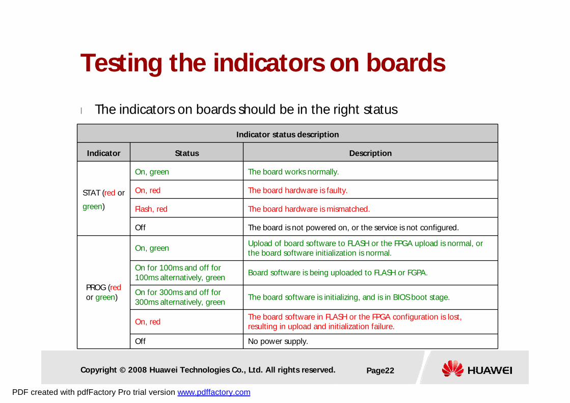
Indicator status description
Indicator Status Description
STAT (red or
green)
On, green The board works normally.
On, red The board hardware is faulty.
Flash, red The board hardware is mismatched.
Off The board is not powered on, or the service is not configured.
PROG (redor green)
On, greenUpload of board software to FLASH or the FPGA upload is normal, or the board software initialization is normal.
On for 100ms and off for 100ms alternatively, green
Board software is being uploaded to FLASH or FGPA.
On for 300ms and off for 300ms alternatively, green
The board software is initializing, and is in BIOS boot stage.
On, redThe board software in FLASH or the FPGA configuration is lost, resulting in upload and initialization failure.
Off No power supply.
Testing the indicators on boards
l The indicators on boards should be in the right status
PDF created with pdfFactory Pro trial version www.pdffactory.com
Copyright © 2008 Huawei Technologies Co., Ltd. All rights reserved. Page23
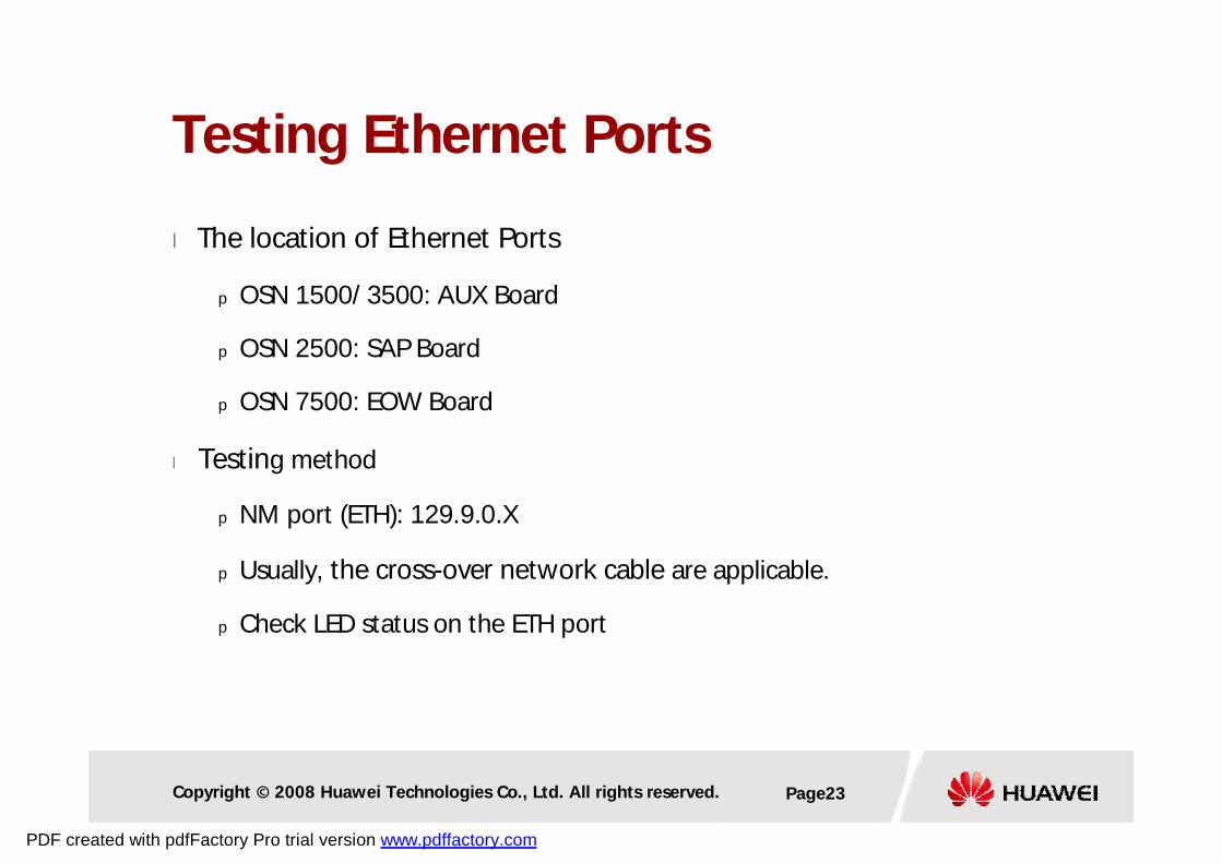
l The location of Ethernet Ports
p OSN 1500/ 3500: AUX Board
p OSN 2500: SAP Board
p OSN 7500: EOW Board
l Testing method
p NM port (ETH): 129.9.0.X
p Usually, the cross-over network cable are applicable.
p Check LED status on the ETH port
Testing Ethernet Ports
PDF created with pdfFactory Pro trial version www.pdffactory.com
Copyright © 2008 Huawei Technologies Co., Ltd. All rights reserved. Page24
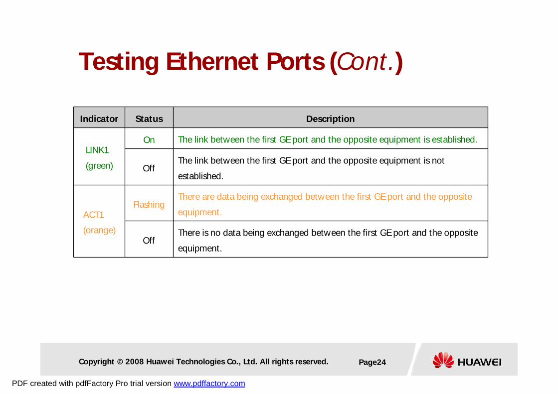
Indicator Status Description
LINK1
(green)
On The link between the first GE port and the opposite equipment is established.
OffThe link between the first GE port and the opposite equipment is not
established.
ACT1
(orange)
FlashingThere are data being exchanged between the first GE port and the opposite
equipment.
OffThere is no data being exchanged between the first GE port and the opposite
equipment.
Testing Ethernet Ports (Cont.)
PDF created with pdfFactory Pro trial version www.pdffactory.com
Copyright © 2008 Huawei Technologies Co., Ltd. All rights reserved. Page25
l Setting NE ID
l Setting NE IP address and gateway IP, if need
p Note: SCC will reboot automatically
l Delivering Commissioning Data
p Make configured services run through all boards and buses
n All ports of all tributary boards
n All buses of each line board
Configuring Commissioning Data
PDF created with pdfFactory Pro trial version www.pdffactory.com
Copyright © 2008 Huawei Technologies Co., Ltd. All rights reserved. Page26
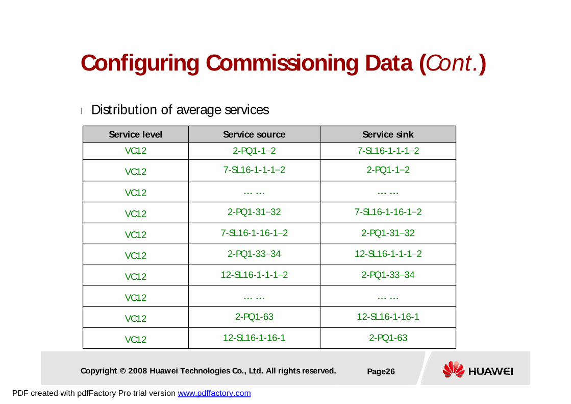
l Distribution of average services
Service level Service source Service sink
VC12 2-PQ1-1–2 7-SL16-1-1-1–2
VC12 7-SL16-1-1-1–2 2-PQ1-1–2
VC12 …… ……
VC12 2-PQ1-31–32 7-SL16-1-16-1–2
VC12 7-SL16-1-16-1–2 2-PQ1-31–32
VC12 2-PQ1-33–34 12-SL16-1-1-1–2
VC12 12-SL16-1-1-1–2 2-PQ1-33–34
VC12 …… ……
VC12 2-PQ1-63 12-SL16-1-16-1
VC12 12-SL16-1-16-1 2-PQ1-63
Configuring Commissioning Data (Cont.)
PDF created with pdfFactory Pro trial version www.pdffactory.com
Copyright © 2008 Huawei Technologies Co., Ltd. All rights reserved. Page27
Testing the ALMC Button on the SCC
l Testing method
p Remove the input fiber jumper, then the buzzer is triggered
p Cut off the alarm sound temporarily
n Press it in a short time, then the alarm sound disappeared.
p Cut off the alarm sound permanently
n Press it for more than 3 seconds
n The ALMC indicator turns yellow
n Reconnect the fiber jumper, then remove it again
n The buzzer will not beep
n Cancel the permanent cut-off status after the test
PDF created with pdfFactory Pro trial version www.pdffactory.com
Copyright © 2008 Huawei Technologies Co., Ltd. All rights reserved. Page28
l Testing method
p Press the RESET button to reset the SCC board.
p The SCC will reset after two minutes.
p The NE can be logged in and is in the running state again.
Testing the RESET Button on SCC
PDF created with pdfFactory Pro trial version www.pdffactory.com
Copyright © 2008 Huawei Technologies Co., Ltd. All rights reserved. Page29
l Testing method
p Check the cable and connection for the alarm output cable.
p Remove the input fiber jumper, the buzzer will beep.
p The centralized alarm processing device will give corresponding
audible and visual indications.
Testing the Centralized Alarm System
PDF created with pdfFactory Pro trial version www.pdffactory.com
Copyright © 2008 Huawei Technologies Co., Ltd. All rights reserved. Page30
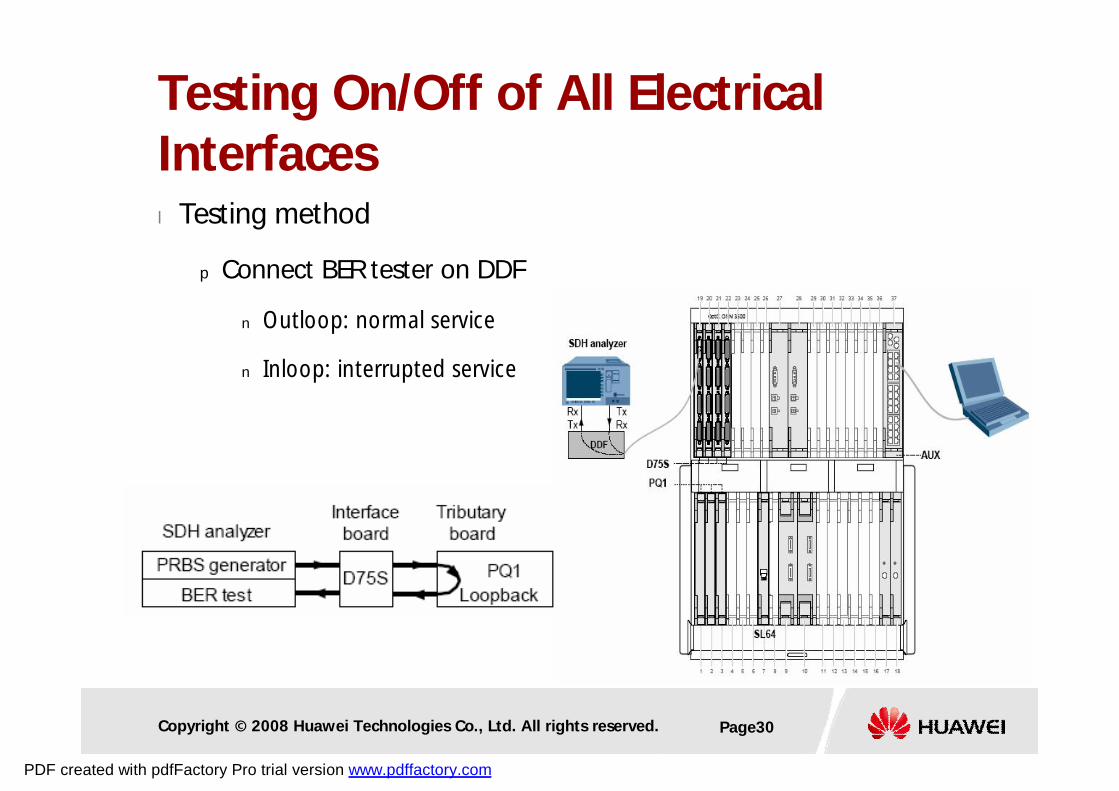
l Testing method
p Connect BER tester on DDF
n Outloop: normal service
n Inloop: interrupted service
Testing On/Off of All Electrical Interfaces
PDF created with pdfFactory Pro trial version www.pdffactory.com
Copyright © 2008 Huawei Technologies Co., Ltd. All rights reserved. Page31
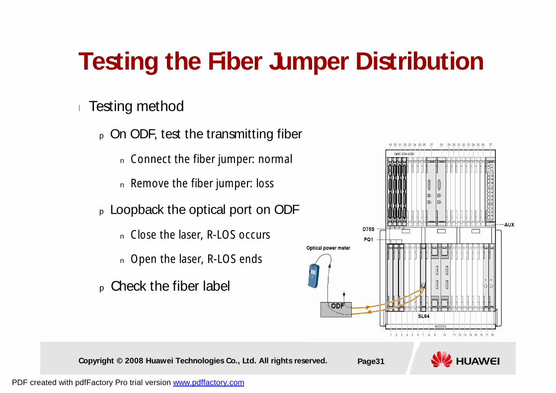
l Testing method
p On ODF, test the transmitting fiber
n Connect the fiber jumper: normal
n Remove the fiber jumper: loss
p Loopback the optical port on ODF
n Close the laser, R-LOS occurs
n Open the laser, R-LOS ends
p Check the fiber label
Testing the Fiber Jumper Distribution
PDF created with pdfFactory Pro trial version www.pdffactory.com
Copyright © 2008 Huawei Technologies Co., Ltd. All rights reserved. Page32
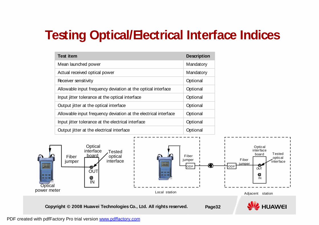
Test item Description
Mean launched power Mandatory
Actual received optical power Mandatory
Receiver sensitivity Optional
Allowable input frequency deviation at the optical interface Optional
Input jitter tolerance at the optical interface Optional
Output jitter at the optical interface Optional
Allowable input frequency deviation at the electrical interface Optional
Input jitter tolerance at the electrical interface Optional
Output jitter at the electrical interface Optional
Testedoptical
interface
Opticalinterfaceboard
IN
OUT
Fiberjumper
-
Opticalpower meter
Testing Optical/Electrical Interface Indices
Opticalinterface
board Testedoptical
interface
IN
OUT
Fiberjumper
- ODF ODF
Fiberjumper
Adjacent stationLocal station
PDF created with pdfFactory Pro trial version www.pdffactory.com
Copyright © 2008 Huawei Technologies Co., Ltd. All rights reserved. Page33
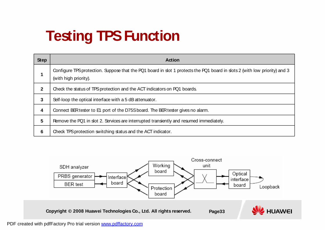
Step Action
1Configure TPS protection. Suppose that the PQ1 board in slot 1 protects the PQ1 board in slots 2 (with low priority) and 3
(with high priority).
2 Check the status of TPS protection and the ACT indicators on PQ1 boards.
3 Self-loop the optical interface with a 5 dB attenuator.
4 Connect BER tester to E1 port of the D75S board. The BER tester gives no alarm.
5 Remove the PQ1 in slot 2. Services are interrupted transiently and resumed immediately.
6 Check TPS protection switching status and the ACT indicator.
Testing TPS Function
PDF created with pdfFactory Pro trial version www.pdffactory.com
Copyright © 2008 Huawei Technologies Co., Ltd. All rights reserved. Page34
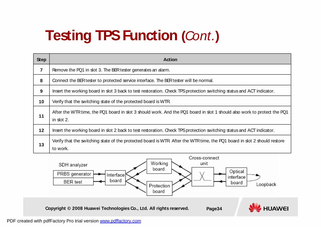
Step Action
7 Remove the PQ1 in slot 3. The BER tester generates an alarm.
8 Connect the BER tester to protected service interface. The BER tester will be normal.
9 Insert the working board in slot 3 back to test restoration. Check TPS protection switching status and ACT indicator.
10 Verify that the switching state of the protected board is WTR.
11After the WTR time, the PQ1 board in slot 3 should work. And the PQ1 board in slot 1 should also work to protect the PQ1
in slot 2.
12 Insert the working board in slot 2 back to test restoration. Check TPS protection switching status and ACT indicator.
13Verify that the switching state of the protected board is WTR. After the WTR time, the PQ1 board in slot 2 should restore
to work.
Testing TPS Function (Cont.)
PDF created with pdfFactory Pro trial version www.pdffactory.com
Copyright © 2008 Huawei Technologies Co., Ltd. All rights reserved. Page35
l Testing method
p Configure boards and services
p Self-loop the optical port on DDF, and connect BER tester
p Switch testn Implement XCS switch (3 methods)
– Issuing switch command by T2000
– Hard reset active board by T2000
– Pull out active board (jiggle switch)
n ACT indicator
n 1+1 XCS protection status
n VC4 services and clock should be good,VC12/VC3 services are momentarily interrupted.
Test Active/Standby XCS
PDF created with pdfFactory Pro trial version www.pdffactory.com
Copyright © 2008 Huawei Technologies Co., Ltd. All rights reserved. Page36
p Restore testn Restore the 1+1 XCS protection through T2000
n ACT indicator
n 1+1 XCS protection status
n VC4 services and clock should be good,VC12/VC3 services are momentarily interrupted.
Test Active/Standby XCS (Cont.)
Notes The interval of active/standby switch should be done after at least 1 min.
PDF created with pdfFactory Pro trial version www.pdffactory.com
Copyright © 2008 Huawei Technologies Co., Ltd. All rights reserved. Page37
l Test method
p Configure boards and services
p Connect BER tester
p Switch test
n Implement GSCC switch (3 methods):
– Issuing switch command by T2000
– Hard reset active board by T2000
– Pull out active board (jiggle switch)
n Services should be normal
n NE can be logged in again
n The consistent configuration on the GSCC and T2000
Testing Active/Standby GSCC
PDF created with pdfFactory Pro trial version www.pdffactory.com
Copyright © 2008 Huawei Technologies Co., Ltd. All rights reserved. Page38
p Restore test
n Restore the 1+1 GSCC protection through T2000
n ACT indicator
n 1+1 GSCC protection status
n Services should be normal
n NE can be logged in again
n The consistent configuration on the GSCC and T2000
Testing Active/Standby GSCC (Cont.)
Notes The interval of active/standby switch should be done after at least 1 min.
PDF created with pdfFactory Pro trial version www.pdffactory.com

Copyright © 2008 Huawei Technologies Co., Ltd. All rights reserved. Page39
l Attention to CXL1/4/16 switch
p CXL1/4/16 = SCC + Cross Connection + Clock + LU
p SCC Unit and Cross Connection Unit switch together
Testing Active/Standby CXL1/4/16
PDF created with pdfFactory Pro trial version www.pdffactory.com
Copyright © 2008 Huawei Technologies Co., Ltd. All rights reserved. Page40
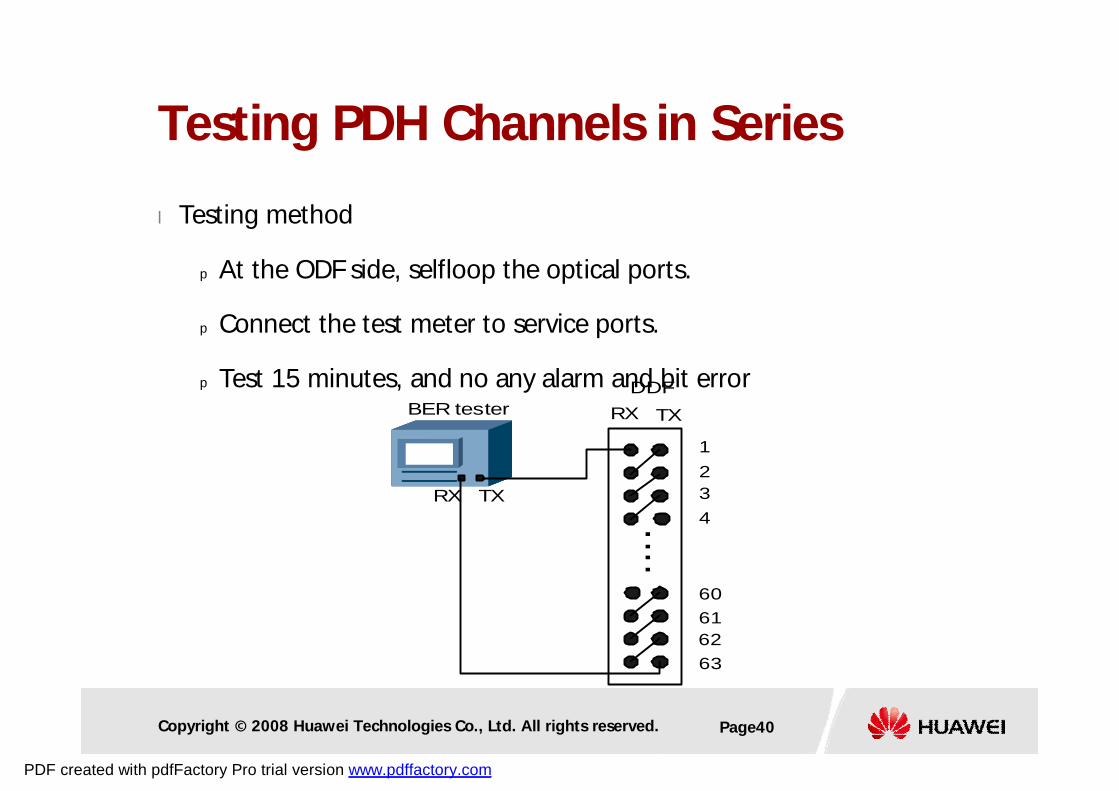
l Testing method
p At the ODF side, selfloop the optical ports.
p Connect the test meter to service ports.
p Test 15 minutes, and no any alarm and bit error
Testing PDH Channels in Series
RX TX
TXRX
BER testerDDF
1234....
63626160
PDF created with pdfFactory Pro trial version www.pdffactory.com
Copyright © 2008 Huawei Technologies Co., Ltd. All rights reserved. Page41
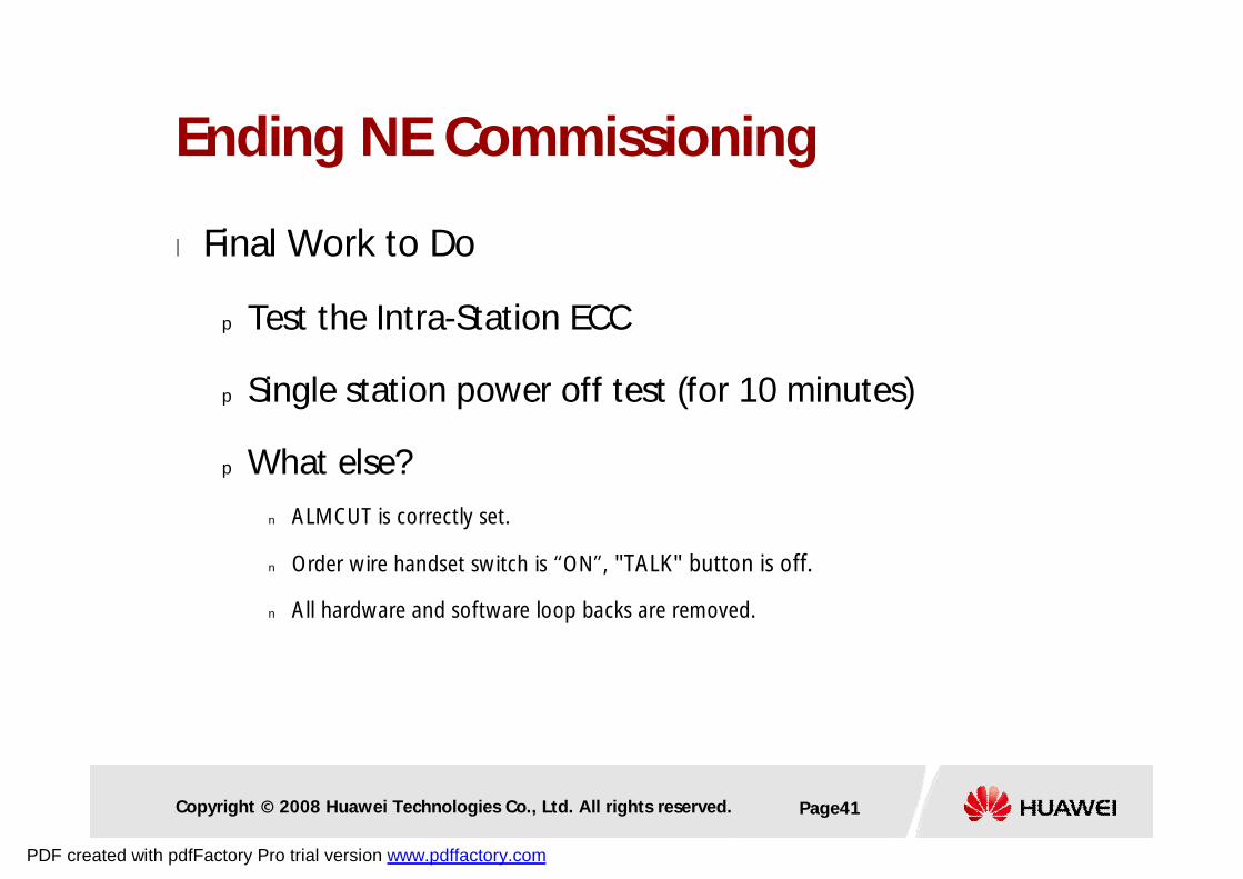
l Final Work to Do
p Test the Intra-Station ECC
p Single station power off test (for 10 minutes)
p What else?
n ALMCUT is correctly set.
n Order wire handset switch is “ON”, "TALK" button is off.
n All hardware and software loop backs are removed.
Ending NE Commissioning
PDF created with pdfFactory Pro trial version www.pdffactory.com
Copyright © 2008 Huawei Technologies Co., Ltd. All rights reserved. Page42
Contents
1. Preparations before Commissioning
2. Single Station Commissioning
3. Network Commissioning
PDF created with pdfFactory Pro trial version www.pdffactory.com
Copyright © 2008 Huawei Technologies Co., Ltd. All rights reserved. Page43
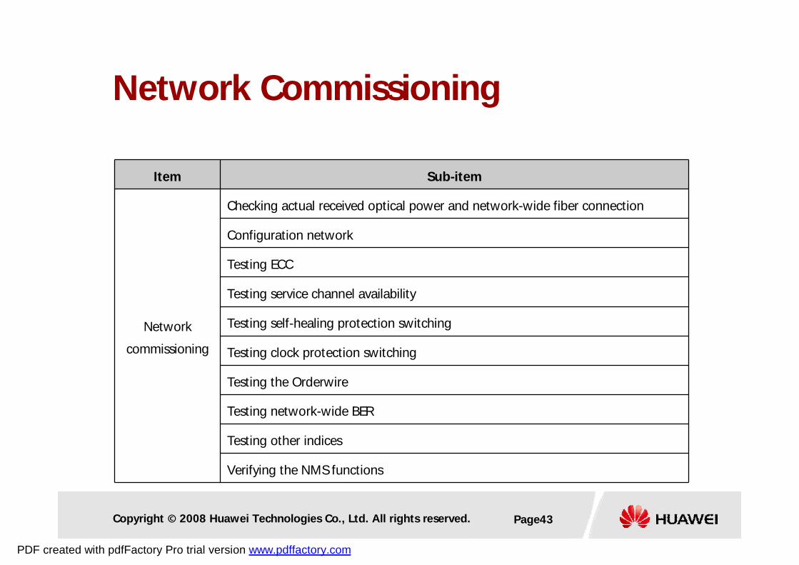
Item Sub-item
Network
commissioning
Checking actual received optical power and network-wide fiber connection
Configuration network
Testing ECC
Testing service channel availability
Testing self-healing protection switching
Testing clock protection switching
Testing the Orderwire
Testing network-wide BER
Testing other indices
Verifying the NMS functions
Network Commissioning
PDF created with pdfFactory Pro trial version www.pdffactory.com
Copyright © 2008 Huawei Technologies Co., Ltd. All rights reserved. Page44
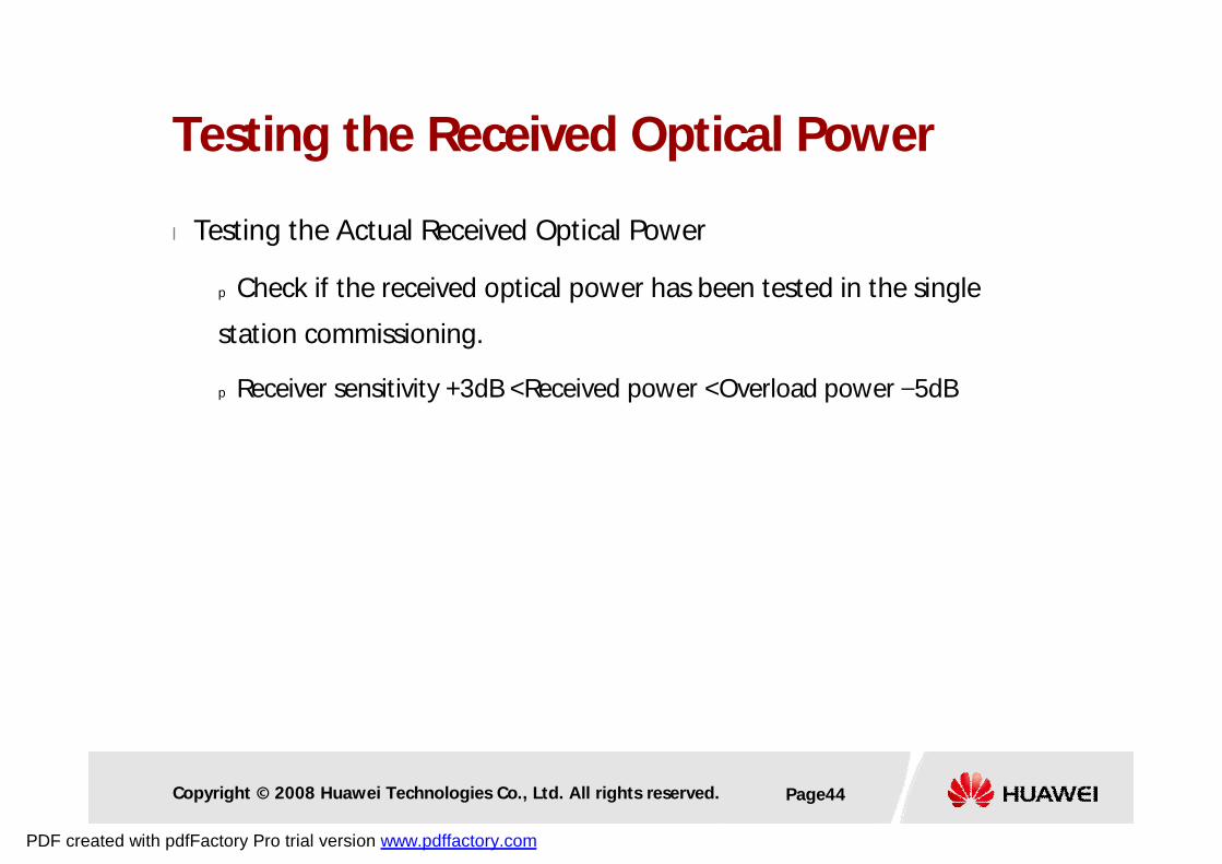
l Testing the Actual Received Optical Power
p Check if the received optical power has been tested in the single
station commissioning.
p Receiver sensitivity +3dB <Received power <Overload power –5dB
Testing the Received Optical Power
PDF created with pdfFactory Pro trial version www.pdffactory.com
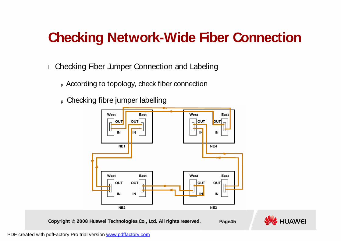
Copyright © 2008 Huawei Technologies Co., Ltd. All rights reserved. Page45
l Checking Fiber Jumper Connection and Labeling
p According to topology, check fiber connection
p Checking fibre jumper labelling
Checking Network-Wide Fiber Connection
PDF created with pdfFactory Pro trial version www.pdffactory.com
Copyright © 2008 Huawei Technologies Co., Ltd. All rights reserved. Page46
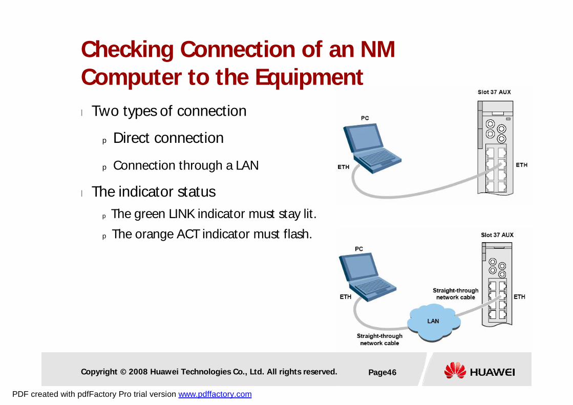
l Two types of connection
p Direct connection
p Connection through a LAN
l The indicator status
p The green LINK indicator must stay lit.
p The orange ACT indicator must flash.
Checking Connection of an NM Computer to the Equipment
PDF created with pdfFactory Pro trial version www.pdffactory.com
Copyright © 2008 Huawei Technologies Co., Ltd. All rights reserved. Page47
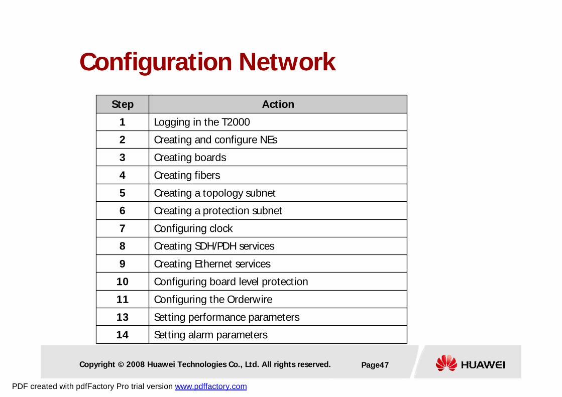
Configuration Network
Step Action
1 Logging in the T2000
2 Creating and configure NEs
3 Creating boards
4 Creating fibers
5 Creating a topology subnet
6 Creating a protection subnet
7 Configuring clock
8 Creating SDH/PDH services
9 Creating Ethernet services
10 Configuring board level protection
11 Configuring the Orderwire
13 Setting performance parameters
14 Setting alarm parameters
PDF created with pdfFactory Pro trial version www.pdffactory.com
Copyright © 2008 Huawei Technologies Co., Ltd. All rights reserved. Page48
l NE login test
p All NEs can be logged in
l ECC automatic routing test
p By default, the short ECC route is used.
l Single-route ECC test
p The single-route ECC route is available, if cut off the other fibers.
p Test another direction
l ECC pass-through test
p Pull out SCC board in ADM NE, and other NEs can be logged in.
l Extended ECC test
Testing ECC
PDF created with pdfFactory Pro trial version www.pdffactory.com
Copyright © 2008 Huawei Technologies Co., Ltd. All rights reserved. Page49
STM-64 two-fiberbidirectional MSP Ring
STM-16non- protection chain
NE1
NE2 NE3NE4
loopback
BER tester
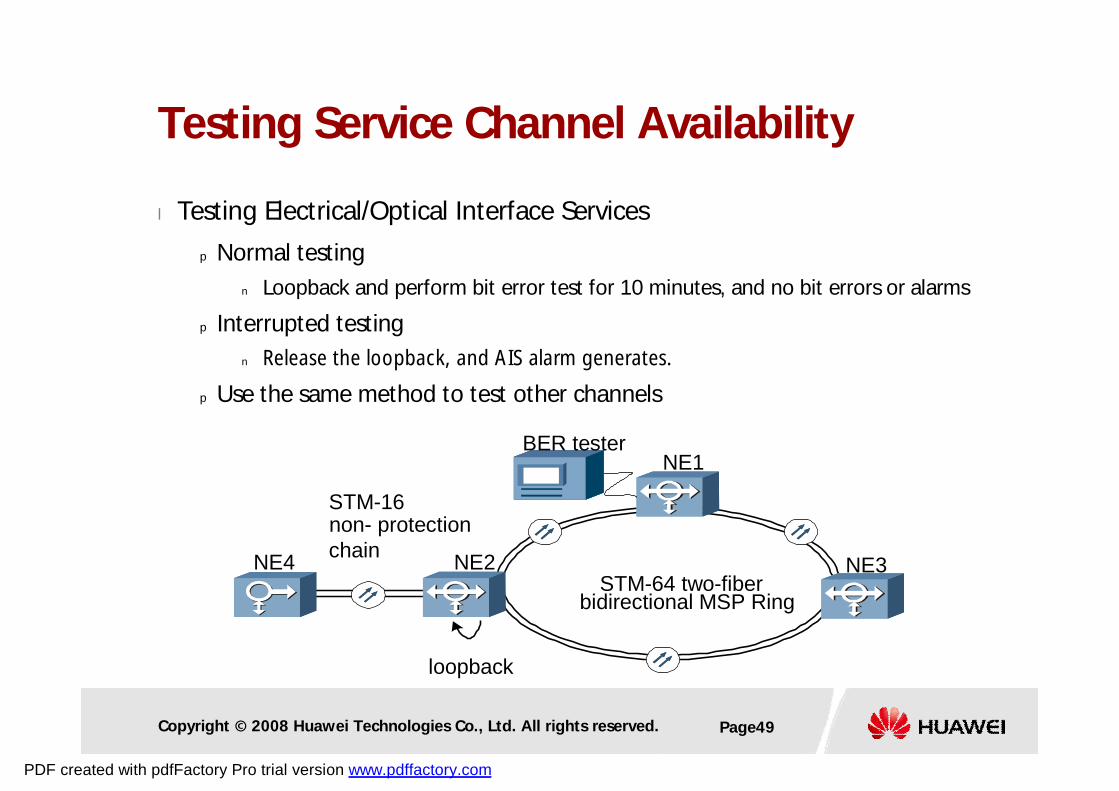
Testing Service Channel Availability
l Testing Electrical/Optical Interface Services
p Normal testing
n Loopback and perform bit error test for 10 minutes, and no bit errors or alarms
p Interrupted testing
n Release the loopback, and AIS alarm generates.
p Use the same method to test other channels
PDF created with pdfFactory Pro trial version www.pdffactory.com
Copyright © 2008 Huawei Technologies Co., Ltd. All rights reserved. Page50
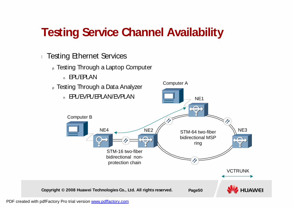
l Testing Ethernet Services
p Testing Through a Laptop Computer
n EPL/EPLAN
p Testing Through a Data Analyzer
n EPL/EVPL/EPLAN/EVPLAN
STM-64 two-fiberbidirectional MSP
ring
STM-16 two-fiberbidirectional non-protection chain
NE1
NE2 NE3NE4
Computer A
VCTRUNK
Computer B
Testing Service Channel Availability
PDF created with pdfFactory Pro trial version www.pdffactory.com
Copyright © 2008 Huawei Technologies Co., Ltd. All rights reserved. Page51
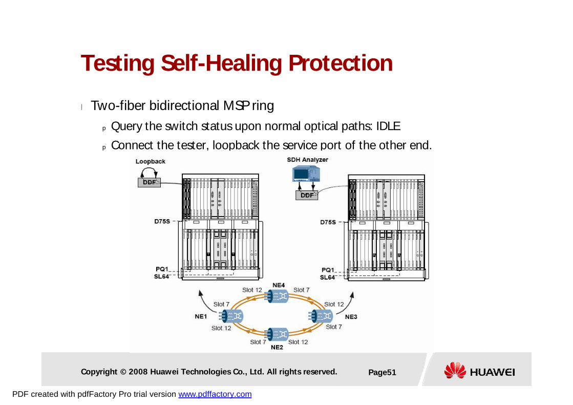
l Two-fiber bidirectional MSP ring
p Query the switch status upon normal optical paths: IDLE
p Connect the tester, loopback the service port of the other end.
Testing Self-Healing Protection
PDF created with pdfFactory Pro trial version www.pdffactory.com
Copyright © 2008 Huawei Technologies Co., Ltd. All rights reserved. Page52
l Two-fiber bidirectional MSP ring
p Test switching by removing fibers or shutting down the laser.
n Proper switch status
n Switch completion in 50ms
n Proper alarms or performance are reported
n Services can be protected
p Test restoration
p Test MSP switch for each section repeatedly
p Test MSP switch when powering OFF
p Test other external switch functions
Testing Self-Healing Protection (Cont.)
PDF created with pdfFactory Pro trial version www.pdffactory.com
Copyright © 2008 Huawei Technologies Co., Ltd. All rights reserved. Page53
l Four-fiber bidirectional MSP ring
p Test the span switch
p Test the ring switch
l 1+1 and 1:N linear MSP
p Test switch of each section in turn
p Dual-End Switching and Single-End Switching
p Revertive and non-revertive mode
l SNCP
p Delay time = 0
p Revertive and non-revertive mode
p Test switch of each section in turn
Testing Self-Healing Protection (Cont.)
PDF created with pdfFactory Pro trial version www.pdffactory.com
Copyright © 2008 Huawei Technologies Co., Ltd. All rights reserved. Page54
l Testing Clock Protection Switching
p Switch and restoration
l Testing Orderwire
p Testing the Addressing Call
p Testing the Conference Call
p Testing Orderwire Functions by Removing Fibers in the ring
p Testing Orderwire upon Orderwire Pass-through
p Testing Subnet Outgoing Orderwire
Testing Clock Protection and Orderwire
PDF created with pdfFactory Pro trial version www.pdffactory.com
Copyright © 2008 Huawei Technologies Co., Ltd. All rights reserved. Page55
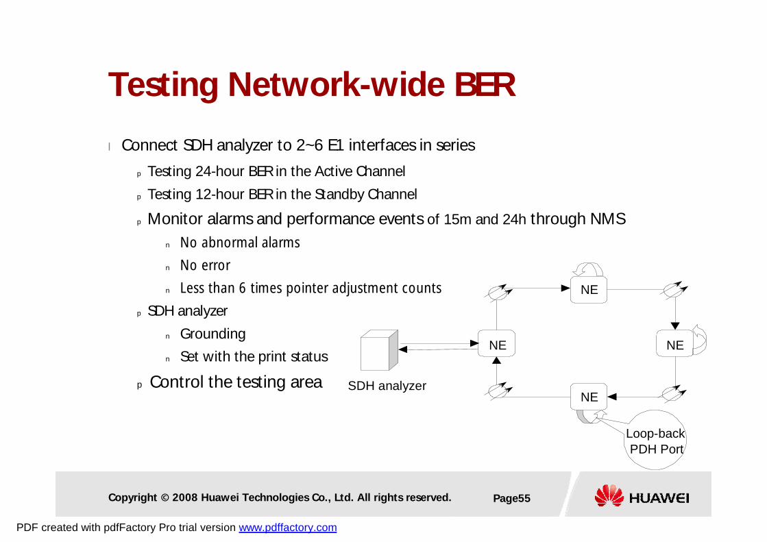
l Connect SDH analyzer to 2~6 E1 interfaces in series
p Testing 24-hour BER in the Active Channel
p Testing 12-hour BER in the Standby Channel
p Monitor alarms and performance events of 15m and 24h through NMS
n No abnormal alarms
n No error
n Less than 6 times pointer adjustment counts
p SDH analyzer
n Grounding
n Set with the print status
p Control the testing area
Testing Network-wide BER
NE
NE
NE
NESDH analyzer
Loop-back PDH Port
PDF created with pdfFactory Pro trial version www.pdffactory.com
Copyright © 2008 Huawei Technologies Co., Ltd. All rights reserved. Page56
l Test other indices
p Jitter, frequency deviation …
l NM function verification
l Remote maintenance function verification
Other Testing Items
PDF created with pdfFactory Pro trial version www.pdffactory.com
Copyright © 2008 Huawei Technologies Co., Ltd. All rights reserved. Page57
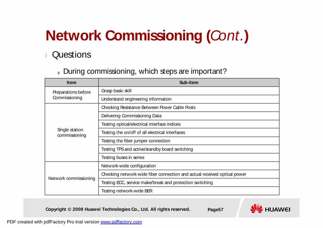
l Questions
p During commissioning, which steps are important?Item Sub-item
Preparations before Commissioning
Grasp basic skill
Understand engineering information
Single station commissioning
Checking Resistance Between Power Cable Posts
Delivering Commissioning Data
Testing optical/electrical interface indices
Testing the on/off of all electrical interfaces
Testing the fiber jumper connection
Testing TPS and active/standby board switching
Testing buses in series
Network commissioning
Network-wide configuration
Checking network-wide fiber connection and actual received optical power
Testing ECC, service make/break and protection switching
Testing network-wide BER
Network Commissioning (Cont.)
PDF created with pdfFactory Pro trial version www.pdffactory.com

Thank youwww.huawei.com
PDF created with pdfFactory Pro trial version www.pdffactory.com