Embed Size (px)
Citation preview
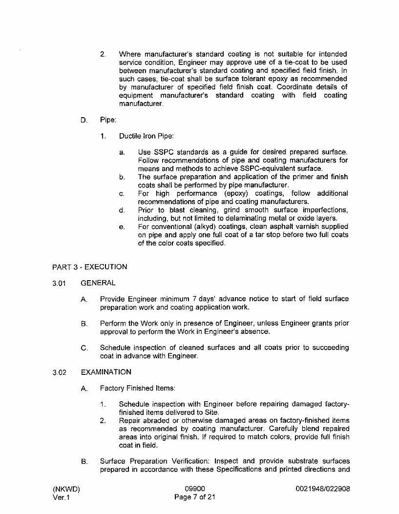
2. Where manufacturer’s standard coating is not suitable for intended service condition, Engineer may approve use of a tie-coat to be used between manufacturer’s standard coating and specified field finish. In such cases, tie-coat shall be surface tolerant epoxy as recommended by manufacturer of specified field finish coat. Coordinate details of equipment manufacturer’s standard coating with field coating manufacturer.
D. Pipe:
1. Ductile Iron Pipe:
a.
b.
C.
d.
e.
Use SSPC standards as a guide for desired prepared surface. Follow recommendations of pipe and coating manufacturers for means and methods to achieve SSPC-equivalent surface. The surface preparation and application of the primer and finish coats shall be performed by pipe manufacturer. For high performance (epoxy) coatings, follow additional recommendations of pipe and coating manufacturers. Prior to blast cleaning, grind smooth surface imperfections, including, but not limited to delaminating metal or oxide layers. For conventional (alkyd) coatings, clean asphalt varnish supplied on pipe and apply one full coat of a tar stop before two full coats of the color coats specified.
PART 3 - EXECUTION
GENERAL
A. Provide Engineer minimum 7 days’ advance notice to start of field surface preparation work and coating application work.
Perform the Work only in presence of Engineer, unless Engineer grants prior approval to perform the Work in Engineer’s absence.
Schedule inspection of cleaned surfaces and all coats prior to succeeding coat in advance with Engineer.
8.
C.
EXAM I NATl ON
A.
B.
Factory Finished Items:
1 .
2.
Schedule inspection with Engineer before repairing damaged factory- finished items delivered to Site. Repair abraded or otherwise damaged areas on factory-finished items as recommended by coating manufacturer. Carefully blend repaired areas into original finish. If required to match colors, provide full finish coat in field.
Surface Preparation Verification: Inspect and provide substrate surfaces prepared in accordance with these Specifications and printed directions and
(NKWD) Ver. 1
09900 Page 7 of 21
0021 948/022908

recommendations of paint manufacturer whose product is to be applied. The more stringent requirements shall apply.
3.03 PROTECTION OF ITEMS NOT TO BE PAINTED
A. Remove, mask, or otherwise protect hardware, lighting fixtures, switchplates, aluminum surfaces, machined surfaces, couplings, shafts, bearings, nameplates on machinery, and other surfaces not specified elsewhere to be painted.
B. Provide drop cloths to prevent paint materials from falling on or marring adjacent surfaces.
C. Protect working parts of mechanical and electrical equipment from damage during surface preparation and painting process.
D. Mask openings in motors to prevent paint and other materials from entering.
E. Protect surfaces adjacent to or downwind of Work area from overspray.
3.04 SURFACE PREPARATION
(NKWD) Ver. 1
A. Field Abrasive Blasting:
1. Perform blasting for items and equipment where specified and as required to restore damaged surfaces previously shop or field blasted and primed or coated.
2. Refer to coating systems for degree of abrasive blasting required. 3. Where the specified degree of surface preparation differs from
manufacturer's recommendations, the more stringent shall apply.
B. Metal Surface Preparation:
1. Where indicated, meet requirements of SSPC Specifications summarized below:
a. SP 1, Solvent Cleaning: Removal of visible oil, grease, soil, drawing and cutting compounds, and other soluble contaminants by cleaning with solvent. SP 2, Hand Tool Cleaning: Removal of loose rust, loose mill scale, loose paint, and other loose detrimental foreign matter, using nonpower hand tools. SP 3, Power Tool Cleaning: Removal of loose rust, loose mill scale, loose paint, and other loose detrimental foreign matter, using power-assisted hand tools. SP 5, White Metal Blast Cleaning: Removal of visible oil, grease, dust, dirt, mill scale, rust, coatings, oxides, corrosion products, and other foreign matter by blast cleaning. SP 6, Commercial Blast Cleaning: Removal of visible oil, grease, dust, dirt, mill scale, rust, coatings, oxides, corrosion products, and other foreign matter, except for random staining limited to no more than 33 percent of each unit area of surface which may consist of light shadows, slight streaks, or minor discolorations
09900 0021 948/022908
b.
c.
d.
e.
Page 8 of 21

2.
3.
4.
5. 6.
7.
f.
9.
h.
I .
caused by stains of rust, stains of mill scale, or stains of previously applied coatings. SP 7, Brush-off Blast Cleaning: Removal of visible rust, oil, grease, soil, dust, loose mill scale, loose rust, and loose coatings. Tightly adherent mill scale, rust, and coating may remain on surface . SP 10, Near-White Blast Cleaning: Removal of visible oil, grease, dust, dirt, mill scale, rust, coatings, oxides, corrosion products, and other foreign matter, except for random staining limited to no more than 5 percent of each unit area of surface which may consist of light shadows, slight streaks, or minor discolorations caused by stains of rust, stains of mill scale, or stains of previously applied coatings. SP 1 1 , Power Tool Cleaning to Bare Metal: Removal of visible oil, grease, dirt, dust, mill scale, rust, paint, oxide, corrosion products, and other foreign matter using power-assisted hand tools capable of producing suitable surface profile. Slight residues of rust and paint may be left in lower portion of pits if original surface is pitted. SP 12, Surface Preparation and Cleaning of Metals by Waterjetting Prior to Recoating: Surface preparation using high- pressure and ultrahigh-pressure water jetting to achieve specified surface cleanliness condition. Surface cleanliness conditions are defined in SSPC SP 12 and are designated WJ-1 through WJ-4 for visual surface preparation definitions and SC-1 through SC-3 for nonvisual surface preparation definitions.
The words “solvent cleaning”, “hand tool cleaning”, “wire brushing”, and “blast cleaning”, or similar words of equal intent in these Specifications or in paint manufacturer’s specification refer to the applicable SSPC Specification. Where OSHA or EPA regulations preclude standard abrasive blast cleaning, wet or vacu-blast methods may be required. Coating manufacturers’ recommendations for wet blast additives and first coat application shall apply. Ductile Iron Pipe Supplied with Asphaltic Varnish Finish: Remove asphaltic varnish finish prior to performing specified surface preparation. Hand tool clean areas that cannot be cleaned by power tool cleaning. Round or chamfer sharp edges and grind smooth burrs, jagged edges, and surface defects. Welds and Adjacent Areas:
a. Prepare such that there is:
1) 2)
3)
No undercutting or reverse ridges on weld bead. No weld spatter on or adjacent to weld or any area to be painted. No sharp peaks or ridges along weld bead.
b. Grind embedded pieces of electrode or wire flush with adjacent surface of weld bead.
(NKWD) Ver. 1
09900 Page 9 of 21
0021 948/022908

8. Preblast Cleaning Requirements:
(NKWD) Ver. 1
a. Remove oil, grease, welding fluxes, and other surface contaminants prior to blast cleaning.
b. Cleaning Methods: Steam, open flame, hot water, or cold water with appropriate detergent additives followed with clean water rinsing.
c. Clean small isolated areas as above or solvent clean with suitable solvent and clean cloth.
9. Blast Cleaning Requirements:
a. Type of Equipment and Speed of Travel: Design to obtain specified degree of cleanliness. Minimum surface preparation is as specified herein and takes precedence over coating manufacturer’s recommendations. Select type and size of abrasive to produce surface profile that meets coating manufacturer’s recommendations for particular primer to be used.
c. Use only dry blast cleaning methods. d. Do not reuse abrasive, except for designed recyclable systems. e. Meet applicable federal, state, and local air pollution and
environmental control regulations for blast cleaning, confined space entry (if required), and disposition of spent aggregate and debris.
b.
I O . Post-Blast Cleaning and Other Cleaning Requirements:
a. Clean surfaces of dust and residual particles from cleaning operations by dry (no oil or water vapor) air blast cleaning or other method prior to painting. Vacuum clean enclosed areas and other areas where dust settling is a problem and wipe with a tack cloth. Paint surfaces the same day they are blasted. Reblast surfaces that have started to rust before they are painted.
b.
C. Galvanized Metal, Copper, and Nonferrous Metal Alloy Surface Preparation:
1.
2.
Remove soil, cement spatter, and other surface dirt with appropriate hand or power tools. Remove oil and grease by wiping or scrubbing surface with suitable solvent, rag, and brush. Use clean solvent and clean rag for final wiping to avoid contaminating surface.
3. Obtain and follow coating manufacturer’s recommendations for additional preparation that may be required.
D. Concrete Surface Preparation:
1. 2.
Do not begin until 30 days after concrete has been placed. Meet requirements of SSPC SP 13.
09900 Page 10 of 21
0021 948/022908
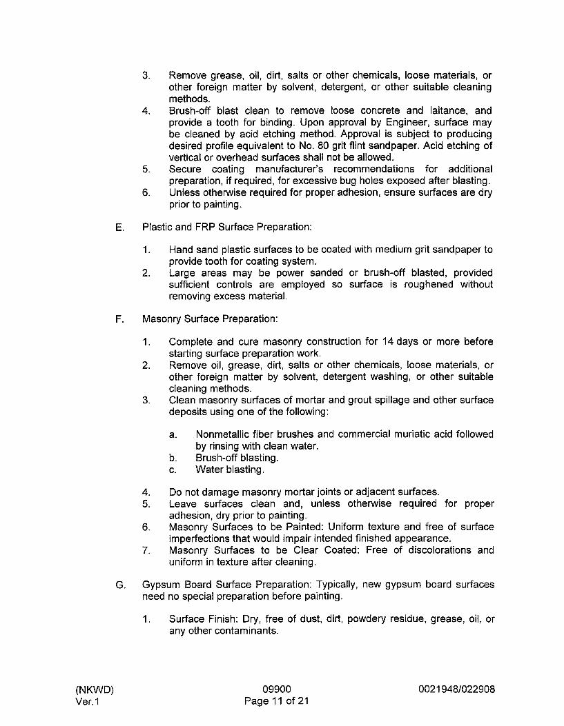
3. Remove grease, oil, dirt, salts or other chemicals, loose materials, or other foreign matter by solvent, detergent, or other suitable cleaning methods.
4. Brush-off blast clean to remove loose concrete and laitance, and provide a tooth for binding. Upon approval by Engineer, surface may be cleaned by acid etching method. Approval is subject to producing desired profile equivalent to No. 80 grit flint sandpaper. Acid etching of vertical or overhead surfaces shall not be allowed.
5. Secure coating manufacturer’s recommendations for additional preparation, if required, for excessive bug holes exposed after blasting.
6. Unless otherwise required for proper adhesion, ensure surfaces are dry prior to painting.
E. Plastic and FRP Surface Preparation:
1.
2.
Hand sand plastic surfaces to be coated with medium grit sandpaper to provide tooth for coating system. Large areas may be power sanded or brush-off blasted, provided sufficient controls are employed so surface is roughened without removing excess material.
F. Masonry Surface Preparation:
1.
2.
Complete and cure masonry construction for 14 days or more before starting surface preparation work. Remove oil, grease, dirt, salts or other chemicals, loose materials, or other foreign matter by solvent, detergent washing, or other suitable cleaning methods. Clean masonry surfaces of mortar and grout spillage and other surface deposits using one of the following:
3.
a.
b. Brush-off blasting. c. Water blasting.
Nonmetallic fiber brushes and commercial muriatic acid followed by rinsing with clean water.
4. Do not damage masonry mortar joints or adjacent surfaces. 5. Leave surfaces clean and, unless otherwise required for proper
adhesion, dry prior to painting. 6. Masonry Surfaces to be Painted: Uniform texture and free of surface
imperfections that would impair intended finished appearance. 7. Masonry Surfaces to be Clear Coated: Free of discolorations and
uniform in texture after cleaning.
G. Gypsum Board Surface Preparation: Typically, new gypsum board surfaces need no special preparation before painting.
1. Surface Finish: Dry, free of dust, dirt, powdery residue, grease, oil, or any other contaminants.
(NKWD) Ver. 1
09900 Page 11 of 21
0021 948/022908

3.05 SURFACE CLEANING
A. Brush-off Blast Cleaning:
(NKWD) Ver. I
1. Equipment, procedure, and degree of cleaning shall meet requirements of SSPC SP 7.
2. Abrasive: Either wet or dry blasting sand, grit, or nutshell. 3. Select various surface preparation parameters, such as size and
hardness of abrasive, nozzle size, air pressure, and nozzle distance from surface such that surface is cleaned without pitting, chipping, or other damage. Verify parameter selection by blast cleaning a trial area that will not be exposed to view. Engineer will review acceptable trial blast cleaned area and use area as a representative sample of surface preparation. Repair or replace surface damaged by blast cleaning.
4.
5.
6.
B. Acid Etching:
1. After precleaning, spread the following solution by brush or plastic sprinkling can: 1 part commercial muriatic acid reduced by 2 parts water by volume. Adding acid to water in these proportions gives an approximate 10 percent solution of HCI.
2. Application:
a. Rate: Approximately 2 gallons per 100 square feet. b. Work acid solution into surface by hard-bristled brushes or
brooms until complete wetting and coverage is obtained. c. Acid will react vigorously for a few minutes, during which time
brushing shall be continued. d. After bubbling subsides (10 minutes), hose down remaining slurry
with high pressure clean water. e. Rinse immediately to avoid formation on the surface of salts that
are difficult to remove. f. Thoroughly rinse to remove any residual acid surface condition
that may impair adhesion.
3. 4.
Ensure surface is completely dry before application of coating. Apply acid etching to obtain a “grit sandpaper” surface profile. If not, repeat treatment.
C. Solvent Cleaning:
1. Consists of removal of foreign matter such as oil, grease, soil, drawing and cutting compounds, and any other surface contaminants by using solvents, emulsions, cleaning compounds, steam cleaning, or similar materials and methods that involve a solvent or cleaning action. Meet requirements of SSPC SP 1. 2.
09900 Page 12 of 21
0021 9481022908

3.06 APPLICATION
A. General:
1.
2.
3.
4.
5. 6.
7.
8.
9.
IO.
11. 12.
The intention of these Specifications is for new, interior and exterior masonry, concrete, and metal, surfaces to be painted, whether specifically mentioned or not, except as specified otherwise. Extent of Coating (Immersion): Coatings shall be applied to internal vessel and pipe surfaces, nozzle bores, flange gasket sealing surfaces, carbon steel internals, and stainless steel internals, unless otherwise specified. For coatings subject to immersion, obtain full cure for completed system. Consult coatings manufacturer’s written instructions for these requirements. Do not immerse coating until completion of curing cycle. Apply coatings in accordance with these Specifications and paint manufacturers’ printed recommendations and special details. The more stringent requirements shall apply. Allow sufficient time between coats to assure thorough drying of previously applied paint. Sand wood lightly between coats to achieve required finish. Vacuum clean surfaces free of loose particles. Use tack cloth just prior to applying next coat. Fusion Bonded Coatings Method Application: Electrostatic, fluidized bed, or flocking. Coat units or surfaces to be bolted together or joined closely to structures or to one another prior to assembly or installation. Water-Resistant Gypsum Board: Use only solvent type paints and coatings. On pipelines, terminate coatings along pipe runs to 1 inch inside pipe penetrations. Keep paint materials sealed when not in use. Where more than one coat is applied within a given system, alternate colors to provide a visual reference showing required number of coats have been applied.
B. Galvanized Metal, Copper, and Nonferrous Metal Alloys:
1. Concealed galvanized, copper, and nonferrous metal alloy surfaces (behind building panels or walls) do not require painting, unless specifically indicated herein. Prepare surface and apply primer in accordance with System No. IO specification. Apply intermediate and finish coats of the coating system appropriate for the exposure.
2.
3.
C. Porous Surfaces, Such As Concrete and Masonry:
1. Filler/Surfacer: Use coating manufacturer’s recommended product to fill air holes, bug holes, and other surface voids or defects.
2. Prime Coat: May be thinned to provide maximum penetration and adhesion I
(NKWD) Ver. 1
09900 Page 13 of 21
0021 948/022908

a. Type and Amount of Thinning: Determined by paint manufacturer and dependent on surface density and type of coating.
3. Surface Specified to Receive Water Base Coating: Damp, but free of running water, just prior to application of coating.
D. Film Thickness and Coverage:
1. Number of Coats:
a. b.
Minimum required without regard to coating thickness. Additional coats may be required to obtain minimum required paint thickness, depending on method of application, differences in manufacturers’ products, and atmospheric conditions.
2. Application Thickness:
a. b.
Do not exceed coating manufacturer’s recommendations. Measure using a wet film thickness gauge to ensure proper coating thickness during application.
3. Film Thickness Measurements and Electrical Inspection of Coated Surfaces:
a. b. Recoat and repair as necessary for compliance with
c. Coats are subject to inspection by Engineer and coating
Perform with properly calibrated instruments.
Specification.
manufacturer’s representative.
4. Visually inspect concrete, masonry, nonferrous metal, plastic, and wood surfaces to ensure proper and complete coverage has been attained.
5. Give particular attention to edges, angles, flanges, and other similar areas, where insufficient film thicknesses are likely to be present, and ensure proper millage in these areas.
6. Apply additional coats as required to achieve complete hiding of underlying coats. Hiding shall be so complete that additional coats would not increase the hiding.
3.07 PROTECTIVE COATINGS SYSTEMS
A. System No. 4 Exposed Metal-Highly Corrosive:
Surface Prep. SP I O , Near-White Blast Cleaning Metal
High Build Epoxy I I coat, 4 MDFT I
(NKWD) Ver. 1
09900 Page 14 of 21
0021 948/022908

B.
C.
D.
E.
F.
G.
- ~ - Surface Prep.
SP I O , Near-White Blast Cleaning
System No. 5 Exposed Metal-Mildly Corrosive:
Paint Material Min. Coats, Cover
Epoxy Primer-Ferrous Metal
I coat, 2.5 MDFT
Surface Prep. Paint Material Min. Coats, Cover
SP 6, Commercial Blast Rust-Inhibitive Primer 1 coat, 2 MDFT Cleaning
~~ -__. Alkyd Enamel 2 coats, 4 MDFZ
I I Polyurethane Enamel b c o a t , 3 MDFT _1
Surface Prep. Paint Material Min. Coats, Cover
In accordance with Epoxy Nonskid 1 coat, 160 SFPG Paragraph Concrete (Aggregated)
--_ . Surface Preparation
System No. 6 Exposed Metal-Atmospheric:
~ - . -
- Surface Prep.
In accordance with Paragraph Plastic and FRP Surface Preparation
Paint Material Min. Coats, Cover
Acrylic Latex Semigloss 2 coats, 320 SFPGPC
- Surface Prep.
In accordance with Paragraph Galvanized Metal, Copper, and Nonferrous Metal Alloy Surface Preparation
Solvent Clean (SP 1)
I
Paint Material
Epoxy Primer-Other
Prime in accordance with manufacturer’s recommendations
Bituminous Paint 1 coat, 10 MDFT
System No. 21 Skid-Resistant-Concrete:
Min. Coats, Cover
As recommended by coating manufacturer
Remaining coats as required for exposure
(NKWD) Ver. I
09900 Page 15 of 21
0021 9481022908

3.08 ARCHITECTURAL PAINT SYSTEMS
Paint Material
Manufacturer’s Paragraph Galvanized Recommended Primer Metal, Copper, and Nonferrous Metal Alloy
--I__
Alkyd Enamel Semigloss)
A.
B.
C.
-111
Min. Coats, Cover 1 1 - 1
1 coat, as recommended by manufacturer
2 coats, 4 MDFT
Surface Prep.
In accordance with Paragraph Masonry Surface Preparation I
-II
System No. 109 Masonry, Semigloss: - I
Paint Material Min. Coats, Cover
1 coat, 75 SFPG Block Filler
Acrylic Latex (Semigloss)
2 coats, 240 SFPGPC
Surface Prep.
In accordance with Paragraph Gypsum Board Surface Preparation
System No. 1 15 Gypsum Board and Plaster, Semigloss:
Paint Material Min. Coats, Cover
1 coat, 350 SFPG Latex PrimerlSealer
Acrylic Latex (Semigloss) or Alkyd
(Semigloss)
2 coats, 400 SFPGPC
3.09 COLORS
A. Provide as selected by Owner or Engineer.
B. Proprietary identification of colors is for identification only. Selected manufacturer may supply matches.
C. Pipe Identification Painting:
I. Color code nonsubmerged metal piping except electrical conduit. Paint fittings and valves the same color as pipe, except equipment isolation valves. On exposed stainless steel piping, apply color 24 inches in length along pipe axis at connections to equipment, valves, or branch fittings, at wall boundaries, and at intervals along piping not greater than 9 feet on center.
2.
(NKWD) Ver. I
09900 Page 16 of 21
0021 9481022908

3.
4. 5.
6.
Pipe Supports: Mild steel, painted No. 70 light gray as specified in ANSI 359-A, as manufactured by Tnemec Co., No. BJ45. Paint all PVC piping as noted in Pipe System Color Code. Pipe System Color Code: To comply with pipe identification system used on existing plant. Pipe Labels and Flow Direction Arrows (stencil painted on pipe):
a. Lettering and Arrows: Black print. b. Background: OSHA safety yellow. c. Label, Lettering Size, and Color: ANSI A13.1 d. Message: See Piping Schedule.
7. Identification Labels:
a. Pipe Labels and Flow Indication Arrows:
1) Locate at all connections to equipment, valves, or branching fittings at wall boundaries.
2) At intervals along piping not greater than 18 feet on center with at least one label applied to each exposed horizontal and vertical run of pipe.
3) At exposed piping not normally in view, such as above suspended ceilings and in closets and cabinets.
4) Application: To pipe only after painting in vicinity is complete or as approved by Engineer.
b. Colors: Provide as designated herein. c. Proprietary identification of colors is for identification only.
Selected manufacturer may supply matches. d. In situations where two colors do not have sufficient contrast to
easily differentiate between them, a six-inch band of contrasting color should be on one of the pipes at approximately 30 inch intervals. The name of the liquid or gas should also be on the pipe. Provide arrows indicating the direction of flow.
D. Equipment Colors:
1.
2. 3.
Equipment includes the machinery or vessel itself plus the structural supports and fasteners and attached electrical conduits. Paint equipment and piping one color as selected. Paint nonsubmerged portions of equipment the same color as the piping it serves, except as itemized below:
a. b. c. Radiation Hazards: OSHA Purple. d.
Dangerous Parts of Equipment and Machinery: OSHA Orange. Fire Protection Equipment and Apparatus: OSHA Red.
Physical hazards in normal operating area and energy lockout devices, including, but not limited to, electrical disconnects for equipment and equipment isolation valves in air and liquid lines under pressure: OSHA Yellow.
(NKWD) Ver. 1
09900 Page 17 of 21
0021 9481022908

4. Fiberglass reinforced plastic (FRP) equipment with an integral colored gel coat does not require painting, provided the color is as selected.
3.10 FIELD QUALITY CONTROL
A. Testing Equipment:
1. Provide magnetic type dry film thickness gauge to test coating thickness specified in mils, as manufactured by Nordson Corp., Anaheim, CA, Mikrotest.
2. Provide low-voltage wet sponge electrical holiday detector to test completed coating systems, 20 mils dry film thickness or less, except zinc primer, high-build elastomeric coatings, and galvanizing, for pinholes, holidays, and discontinuities, as manufactured by Tinker and Rasor, San Gabriel, CA, Model M-I. Provide high-voltage spark tester to test completed coating systems in excess of 20 mils dry film thickness. Unit as recommended by coating m a n ufact u rer.
3.
B. Testing:
1. Thickness and Continuity Testing:
a. Measure coating thickness specified in mils with a magnetic type, dry film thickness gauge, in accordance with SSPC PA 2. Check each coat for correct millage. Do not make measurement before a minimum of 8 hours after application of coating. Holiday detect coatings 20 mils thick or less, except zinc primer and galvanizing, with low voltage wet sponge electrical holiday detector in accordance with NACE RP0188. Holiday detect coatings in excess of 20 mils dry with high voltage spark tester as recommended by coating manufacturer and in accordance with NACE RPOI 88. After repaired and recoated areas have dried sufficiently, retest each repaired area. Final tests may also be conducted by Engineer.
b.
c.
d.
C. Inspection: Leave staging and lighting in place until Engineer has inspected surface or coating. Replace staging removed prior to approval by Engineer. Provide additional staging and lighting as requested by Engineer.
D. Unsatisfactory Application:
1. If item has an improper finish color or insufficient film thickness, clean surface and topcoat with specified paint material to obtain specified color and coverage. Obtain specific surface preparation information from coating manufacturer.
2. Evidence of runs, bridges, shiners, laps, or other imperfections is cause for rejection.
3. Repair defects in accordance with written recommendations of coating manufacturer.
(NKWD) Ver. 1
09900 Page 18 of 21
0021 948/022908
E. Damaged Coatings, Pinholes, and Holidays:
1.
2.
Feather edges and repair in accordance with recommendations of paint manufacturer. Hand or power sand visible areas of chipped, peeled, or abraded paint, and feather the edges. Follow with primer and finish coat. Depending on extent of repair and appearance, a finish sanding and topcoat may be required. Apply finish coats, including touchup and damage-repair coats in a manner that will present a uniform texture and color-matched appearance.
3.
3.1 1 MANUFACTURER’S SERVICES
A. In accordance with Section 01 640, Manufacturers’ Services, coating manufacturer’s representative shall be present at Site as follows:
1. 2.
On first day of application of any coating system. A minimum of one additional Site inspection visits, each for a minimum of 4 hours, in order to provide Manufacturer’s Certificate of Proper Installation. As required to resolve field problems attributable to or associated with manufacturer’s product. To verify full cure of coating prior to coated surfaces being placed into immersion service.
3.
4.
3.12 CLEANUP
A. Place cloths and waste that might constitute a fire hazard in closed metal containers or destroy at end of each day.
B. Upon completion of the Work, remove staging, scaffolding, and containers from Site or destroy in a legal manner.
C. Remove paint spots, oil, or stains upon adjacent surfaces and floors and leave entire job clean.
3.1 3 APPLICATION SCHEDULE
A. As shown in Finish Schedule on Drawings. Additional requirements are included in the Piping Color Coding.
B. Surfaces Not Requiring Painting: Unless otherwise stated or shown below or in other sections, the following areas or items will not require painting or coating:
1. Reinforcing steel. 2. Nonferrous and corrosion-resistant ferrous alloys such as copper,
bronze, Monel, aluminum, chromium plate, atmospherically exposed weathering steel, and stainless steel, except where:
a. Required for electrical insulation between dissimilar metals.
(NKWD) Ver. 1
09900 Page 19 of 21
0021 9481022908

(NKWD) Ver. 1
3.
4.
5.
6.
b. Aluminum and stainless steel are embedded in concrete or masonry, or aluminum is in contact with concrete or masonry.
c. Color coding of equipment and piping is required.
Nonmetallic materials such as glass, wood, and porcelain, except as required for architectural painting or color coding. Prefinished electrical and architectural items such as motor control centers, switchboards, switchgear, panelboards, transformers, disconnect switches (if prefinished in OSHA yellow), acoustical tile, cabinets, building louvers, and wall panels; color coding of equipment is required. Insulated piping and insulated piping with jacket will require prime coat only, except as required for architectural painting or color coding. Fiberglass reinforced plastic (FRP) surfaces with an integral ultra-violet resistant colored gel coat do not require painting, provided the color is as selected.
Unless otherwise shown or specified, paint surfaces in accordance with the following application schedule. In the event of discrepancies or omissions in the following, request clarification from Engineer before starting work in question.
System No. 4 Exposed Metal-Highly Corrosive: Use on the following items or areas:
1. Exposed metal surfaces, located inside or outside of structures and exposed to weather.
System No. 5 Exposed Metal-Mildly Corrosive: Use on the following items or areas:
1. Exposed metal surfaces, located inside or outside of structures and exposed to weather or in a highly humid atmosphere, such as pipe galleries and similar areas.
System No. 6 Exposed Metal-Atmospheric: Use on the following items or areas:
1. Exposed metal surfaces, located inside or outside of structures or exposed to weather, including metal doors and frames, exterior metal ductwork, flashing, sheet metalwork and miscellaneous architectural metal trim , and the following specific surfaces:
a. Inside duct stack heads behind diffusers, registers, and grilles with flat black.
b. Instrumentation and control systems exposed enclosures for process.
2. Apply surface preparation and primer to surfaces prior to installation. Finish coats need only be applied to surfaces exposed after completion of construction.
09900 Page 20 of 21
0021 9481022908

G. System No. 10 Galvanized Metal, Copper, and Nonferrous Metal Alloy Conditioning: Use on the following items or areas:
1. Galvanized surfaces requiring painting. 2. After application of System No. 10, apply finish coats as required for
exposure.
H. System No. 21 Skid-Resistant-Concrete: Use on the following items or areas:
I. As noted on Room Finish Schedule.
J. System No. 27 Aluminum and Dissimilar Metal Insulation: Use on aluminum surfaces embedded or in contact with concrete.
K. System No. 106 Galvanized Metal: Use on the following items or areas:
1. Hollow metal frames and doors.
L. System No. 109 Masonry, Semigloss: Use on the following items or areas:
1. As noted on Room Finish Schedule.
M. System No. 11 5 Gypsum Board and Plaster, Semigloss: Use on the following items or areas:
1. As noted on Room Finish Schedule.
END OF SECTION
(NKWD) Ver. 1
09900 Page21 of21
0021 9481022908


Division 10 - Specialties


SECTION 10200 - LOUVERS
PART 1 - GENERAL
1.01
1.02
1.03
1.04
REFERENCES
A. The following is a list of standards which may be referenced in this section:
1. 2. ASTM International (ASTM):
Air Movement and Control Association (AMCA): Standard 500.
a. A480/A480M, Standard Specification for Stainless and Heat- Resisting Chromium-Nickel Steel Plate, Sheet and Strip.
b. D1187, Standard Specification for Asphalt-Base Emulsions for Use as Protective Coatings for Metal.
c. E84, Standard Test Method for Surface Burning Characteristics of Building Materials.
3. Underwriters Laboratories, Inc. (UL): Building Materials Directory.
DESIGN REQUIREMENTS
Installed Louvers: Capable of resisting wind load of 30 pounds per square foot.
SUBMITTALS
A. Action Submittals:
1. Shop Drawings: Large scale details of louvers, anchorage, and relationship to adjoining construction.
a. Manufacturer’s Literature:
1) Descriptive and performance data of louvers, including
2) Parts list, if applicable. 3) Installation instructions. 4) Maintenance procedures.
standard drawings and louver-free area.
2. Samples: Manufacturer’s standard finishes and colors.
B. Informational Submittals:
1. Factory test data. 2. Certificates of AMCA ratings. 3. Special Guarantee.
SPECIAL GUARANTEE
Manufacturer’s extended guarantee or warranty, with Owner named as beneficiary, in writing, as Special Guarantee. Special Guarantee shall provide for correction, or at option of Owner, removal and replacement of special fluorocarbon or baked-on finish found defective during a period of 2 years after date of Substantial
(NKWD) Ver. 1
10200 Page I of 3
0021 948/031208

Completion. Duties and obligations for correction or removal and replacement of defective Work as specified in General Conditions.
PART 2 - PRODUCTS
2.01 GENERAL
A. Nonacoustical louver sizes are based on 50 percent free area and fpm maximum velocity through free area. If louvers furnished do not meet these parameters, Contractor is responsible for resizing louvers and wall openings, and for making all other adjustments to allow for larger openings.
Water Penetration Rate: No greater than 0.02 ounce per square foot. B.
C. Louvers: Rated and tested in accordance with AMCA Standard 500.
D. Furnish louvers with interior duct collars.
2.02 FIXED STORMPROOF LOUVERS (TYPE SP)
A.
B.
C.
D.
E.
F.
G.
(NKWD) Ver. 1
Frame: Extruded aluminum channel, 0.081 inch thick, 4 inches deep, with concealed mullions.
Blades: Extruded aluminum, 0.081 inch thick, Z-shaped, 35- to 45-degree pitch angle, spaced 3 to 4.25 inches on center.
Pressure Loss: AMCA certified rating of no greater than 0.10-inch WC.
Sizes: On Drawings.
Screen: Inside mounted, painted aluminum, 112-inch mesh.
Finish: Kynar 500 fluorocarbon coating.
Manufacturers and Products:
I . 2. Dowco; Series LEB-4. 3. Ruskin; Model ELF-375DXH.
Construction Specialties; Model 41 I O .
2.03 ACCESSORIES
A.
B. Flashings: Match louver frame.
C.
D.
E. Insulated Blank-Off Panels:
Anchors and Fasteners for Louvers: Stainless steel.
Isolation Tape: Tremco 440, 3M EC1202, or Presstite 579.6.
Isolation Paint: ASTM D1187, bituminous coating.
1. Panels: Urethane core faced on both sides with 0.032-inch stucco embossed 5005-HI34 aluminum sheet in finish and color to match louvers.
10200 0021 948/031208 Page 2 of 3

2.
3.
4. Thickness: 2 inches.
Frames: 6063-T52 extruded aluminum sections 0.080-inch thick, with mitered corners. Perimeter Gaskets: Closed-cell PVC, to ensure tight fit of panel to louver.
2.04 SOURCE QUALITY CONTROL
A. Factory Performance Tests:
1. Airflow versus pressure loss. 2. Rain penetration data. 3. Air infiltration leakage through closed operating louvers.
PART 3 - EXECUTION
3.01 EXAMINATION
A. Check openings to assure that dimensions conform to Drawings.
B. Assure that openings are free of irregularities that would interfere with installation.
C. Do not install louvers until defects have been corrected.
3.02 INSTALLATION
A. Install louvers as shown on reviewed Shop Drawings. Coordinate with heating or ventilation ductwork to be connected.
B. Follow procedures in manufacturer’s recommended installation instructions.
C. Install insulated blank-off panels, completely closing space between ducts and louver frames.
D. Separate aluminum from other metals with isolation tape or paint.
3.03 ADJUSTING AND CLEANING
A. Set adjustable louver blades for uniform alignment in OPEN and CLOSED positions.
B. Adjust louvers so moving parts operate smoothly.
END OF SECTION
(NKWD) Ver. 1
10200 Page 3 of 3
002 1 948103 I 208


SECTION 10400 - IDENTIFYING DEVICES
PART 1 - GENERAL
1.01 REFERENCES
A. The following is a list of standards that may be referenced in this section:
1.
2. ASTM International (ASTM):
American Society of Mechanical Engineers (ASME): A I 3.1 , Scheme for the Identification of Piping Systems.
a. A53, Standard Specification for Pipe, Steel, Black and Hot-
b. 0709, Standard Specification for Laminated Thermosetting Dipped, Zinc-Coated Welded and Seamless.
Materials.
3. The Chlorine Institute, lnc.: WC-1, Wall Chart: Handling Chlorine
4. Cylinders and Ton Containers. National Fire Protection Association (NFPA):
a.
b.
704, Standard System for the Identification of the Hazards of Materials for Emergency Response. HAZ-01, Fire Protection Guide to Hazardous Materials.
5. 6.
Occupational Safety and Health Act (OSHA). U.S. Department of Transportation, Federal Highway Administration: Manual on Uniform Traffic Control Devices for Streets and Highways.
1.02 SUBMITTALS
A. Action Submittals:
1. Shop Drawings:
a.
b.
Drawings showing layouts, actual letter sizes and styles, and Project-specific mounting details. Manufacturer’s literature showing letter sizes and styles, sign materials, and standard mounting details.
2. Samples: One full size for each type of nameplate, sign, and label specified.
B. Informational Submittals: Manufacturer’s installation instructions.
PART 2 - PRODUCTS
2.01 NAME PLAQUE
A. Material: Cast bronze.
(NKWD) Ver. 1
10400 Page 1 of 7
0021 9481022908

B.
C.
D.
E.
F.
G.
H.
I.
Size: 18 inches by 27 inches and minimum 1/4 inch thick.
Lettering and Trim: Raised 1/8 inch, minimum.
Finish:
1. 2.
Lettering and Border Outlines: Hand-tool, clean, and sharp.
Lettering Style: Condensed block.
Tablet Inscription Text: To be furnished by Owner or Engineer.
Fasteners: Concealed.
Manufacturer's name is allowed on backside.
Border Face and Edge, and Lettering Face: Fine satin hand finish. Background: Dark statuary bronze, finely pebbled surface.
2.02 DOOR NAMEPLATES
A.
B.
C.
D.
E.
F.
G.
Material: Plastic with square corners.
Thickness: 1 /8 inch.
Height: 2 inches.
Finish: Nondirectional matte.
Background: Black.
Letters: Engraved.
1. Size: 1 inch high. 2. Color: White. 3. Style: Helvetica medium. 4.
Manufacturers and Products:
1. 2.
Message Text: As shown on Door and Hardware Schedule.
Best Manufacturing Co., Kansas City, MO; System A-101. Andco Industries Corp., Greensboro, NC; 1400 series.
2.03 PICTORIAL SYMBOLS
A.
6.
C. Manufacturers and Products:
Material: Plastic with square corners, match door nameplates.
Conform to ANSI A I 17. I ~ Section 4.30.
1. 2.
Best Manufacturing Co., Kansas City, MO; System A-101. Andco Industries Corp., Greensboro, NC; 1400 series.
(NKWD) 10400 0021 948/022908 Ver. 1 Page 2 of 7
2.04 SIGNS
A.
B.
C.
D.
Plastic Signs (Type A):
1.
2.
3. Rounded corners.
Exterior: Laminated plastic subsurface image type, 3/16 inch thick with high-gloss finish. Interior: Plastic, 1/8 inch thick with nondirectional matte finish and engraved letters.
Fiberglass Signs (Type C):
1. Material: Three-ply laminated fiberglass, minimum 1/8 inch thick, with contrasting color core message layer between two clear weather- resistant surface layers.
a. Best Manufacturing Co. b. Brady Signmark.
2. Manufacturers:
Exit Signs (Type G):
1. Material: Plastic, 118 inch minimum thickness. 2. Letters:
a. 6 inches high, with 3/4-inch stroke. b. 2 inches wide, except for letter “I”, with spacing of 3/8 inch. Colors: Red letters and direction arrows on white background. 3.
Hazardous Material Signals (Type H):
1. Conform to NFPA 704 and NFPA HAZ-01. 2. Material: Reflective sheeting applied to 0.040-inch thick aluminum. 3. Background, Letters, and Numbers: Die-cut vinyl with pressure
sensitive adhesive. 4. Manufacturers:
a. Brady Signmark. b. Emed Co., Inc.
2.05 IDENTIFICATION IABELS
A. Pipe Labels:
1. Labels:
a. Snap-on, reversible type with lettering and directional arrows, sized for outside diameter of pipe and insulation.
b. Provided with ties or straps for pipes of 6 inches and over diameter.
c. Designed to firmly grip pipe so labels remain fixed in vertical pipe runs.
2.
3.
Material: Heavy-duty vinyl or polyester, suitable for exterior use, long lasting, and resistance to moisture, grease, and oils. Letters and Arrows: Black on OSHA safety yellow background.
(NKWD) 10400 0021 948/022908 Ver. 1 Page 3 of 7

4. 5. 6. Manufacturers and Products:
Color Field and Letter Height: Meet ASME A13.1. Message: Piping system name as indicated on Piping Schedule.
a. Brady Signmark; B-915 BradySnap-On and Strap-On Pipe
b. Markers. Seton Identification Products; Ultra-mark Pipe Markers.
B. Pipe Labels:
1. Labels: Self-adhesive tape, with separate directional flow arrow
2. Material: Pressure sensitive vinyl. 3. 4. 5. 6. Manufacturers and Products:
banding tape.
Letters and Arrows: Black on OSHA safety yellow background. Color Field and Letter Height: ASME A13.1. Message: Piping system name as indicated on Piping Schedule.
a. Brady Signmark; B-946 Self-sticking Vinyl Pipe Markers and Directional Flow Arrow Tape.
b. Seton Identification Products; Opti-Code Markers and Arrows- On-A-Roll Tape.
C. Equipment Labels:
1. 2. 3. Background: OSHA safety yellow. 4. Materials:
Applies to equipment with assigned tag numbers, where specified. Letters: Black bold face, 3/4 inch minimum high.
a.
b. Fiberglass with encased lettering.
Aluminum or stainless steel with a baked-on finish suitable for use on wet, oily, exposed, abrasive, and corrosive areas.
5.
6. Size:
Furnish l-inch margin with holes at each end of label, for mounting. On fiberglass labels, furnish grommets at each hole.
a. 2inches minimum and 3inches maximum high, by 14inches
b. minimum and 18 inches maximum long. Furnish same size base dimensions for all labels.
7.
8. Manufacturers:
Message: Equipment names and tag numbers as used in sections where equipment is specified.
a. Brady Signmark. b. Seton Identification Products.
2.06 ANCILLARY MATERIALS
A. Fasteners: Stainless steel screws or bolts of appropriate sizes.
(NKWD) Ver. I
10400 Page 4 of 7
0021 948/022908

B. Wood Posts: Preservative treated 4 by 4 wood as specified in Section 06100, Rough Carpentry.
C. Pipe Posts: 2-1/2-inch galvanized steel pipe meeting ASTM A53, Type S, Grade B.
D. Chain: Type 304 stainless steel, No. 16 single jack chain or No. 2 double loop coil chain.
E. Manufacturer’s standard brackets for wall mounting of two-sided exit signs.
PART 3 - EXECUTION
3.01
3.02
3.03
3.04
INSTALLATION - GENERAL
A.
B.
NAME PLAQUE
Mount with concealed fasteners.
DOOR NAMEPLATES AND PICTORIAL SYMBOLS
A. Attach to doors with self-sticking removable adhesive. See Door and
In accordance with manufacturer’s recommendations.
Mount securely, plumb, and level.
Hardware Schedule for locations and messages.
Mount with bottom of nameplate at 5 feet 6 inches above floor. B.
SIGNS
A. Fasten to walls or posts or hang as scheduled. Anchor in place for easy removal and reinstallation with ordinary hand tools.
Information, Exit, and Safety Signs:
1 I
2.
B.
Install facing traffic. Locate for high visibility with minimum restriction of working area around walkways and equipment. Removable with ordinary hand tools without leaving scars on structure or equipment.
C. Hazardous Material Signals:
1. 2.
3. Specific Materials:
Install where required by NFPA No. 704 and UFC, Chapter 79. Install at entrances to spaces where hazardous materials are stored, dispensed, used, or handled and on sides of stationary tanks.
(NKWD) Ver. 1
10400 Page 5 of 7
0021 9481022908
3.05 IDENTIFICATION LABELS
A. Pipe Labels:
1. Locate at connections to equipment, valves, or branching fittings at wall boundaries.
2. At intervals along piping not greater than 18 feet on center with at least one label applied to each exposed horizontal and vertical run of pipe.
3. At exposed piping not normally in view, such as above suspended ceilings and in closets and cabinets.
4. Supplementary Labels: Provide to Owner those listed on Piping Schedule that do not receive arrows.
5. Application: To pipe only after painting in vicinity is complete or as approved by Engineer.
6. Installation: In accordance with manufacturer’s instructions.
B. Equipment Labels:
1. 2.
Locate and install on equipment or concrete equipment base. Anchor to equipment or base for easy removal and replacement with ordinary hand tools.
3.06 SUPPLEMENTS
A. The supplement listed below, following “End of Section,” is a part of this Specification.
1. Sign Schedule: A tabulation of characteristics and mounting information for each sign. Provide items as scheduled. Meet requirements of Occupational Safety and Health Act (OSHA).
(NKWD) Ver.1
10400 Page 6 of 7
002 I 948/022908
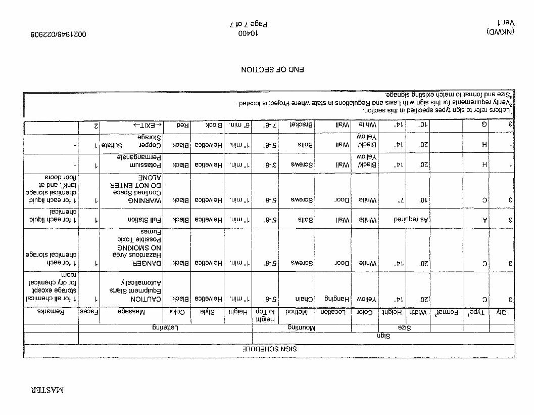
806ZZ0/8P6 LZOO
N01133S A 0 aN3
,,9-,L ,,PI. ‘,01 9 6
,,P1 ,,oz H 1
,,P1 ,,oz H 1 I
j I
‘,L ,,Ob 3 s
I z -~ 1 “9-S
‘U!W “1
,,9-,Ei
“9-S ‘,P 1 -r ,,P 1
IYGlaH a2
3!s 6ui . .- .
31 ta3H3S N9IS


SECTION 10999 - MISCELLANEOUS SPECIALTIES
PART 1 - GENERAL
1.01 SUMMARY
A. Section includes:
1. Portable fire extinguishers. 2. Toilet room accessories.
I .02 REFERENCES
A. The following is a list of standards which may be referenced in this section:
1. ASTM International:
a. A591 , Standard Specification for Steel Sheet, Electrolytic Zinc-Coated, for Light Coating Weight [Mass] Applications.
b. E84, Standard Test Method for Surface Burning Characteristics of Building Materials.
2. Underwriters Laboratories Inc. (UL): Fire Protection Equipment List.
1.03 SUBMITTALS
Action Submittals: Manufacturers’ descriptions, installation data, color charts, and cleaning and service instructions for all items proposed for use. Clearly identify each item.
PART 2 - PRODUCTS
2.01 PORTABLE FiRE EXTINGUISHERS
A. Type: Multipurpose hand fire extinguishers with tri-class dry chemical extinguishing agent in pressurized, red enameled steel shell cylinder; activated by top squeeze handle; agent propelled through hose or opening at top of unit; for use on Class A, B, and C fires; minimum UL rating 4A-60B:CI 10 pound capacity with all accessories necessary to secure extinguishers in position.
B. Manufacturers:
1. Allenco. 2. J.L. Industries. 3. Larsen’s Manufacturing Co.
(NKWD) (Ver. 1)
10999 Page 1 of 2
002 I 948/03 1 708

2.02 TOILET ROOM ACCESSORIES
A. Furnish accessory items listed where indicated by mark or note on Drawings:
-_I Item
Surface Mounted Roll Toilet Paper Dispenser
Wall Mounted Liquid Soap Dispenser
Mirror, Size on Drawings
Surface Mounted Paper Towel Dispenser Mop and Broom Holder (24 inches)
I_
I
Mark Bobrick Bradley
,_ TPD NO. 8-2740 NO 5241-50
SD NO. 8-4112 No. 6542
MIR NO. 8-290 No. 780
PTD NO. 8-262 NO. 250-15 --
M&BH NO. B-223x24 NO. 9953
B. Finish: Satin stainless steel finish.
C. Anchors: Furnish anchors, fasteners, or other devices necessary for a complete, secure installation.
PART 3 - EXECUTION
3.01 INSTALLATION OF SPECIALTIES
A.
B.
C.
D.
Follow manufacturer’s recommendations and printed instructions. Consult with Engineer so that minor adjustments in the locations can be decided if necessary.
I .
2.
Install materials plumb or level as applicable and attach securely to adjacent materials with suitable fasteners. Prevent scratching or damaging adjacent materials during installation.
Portable Fire Extinguishers: Mount hangers securely in position following manufacturer’s recommendation, so that top of extinguisher is no more than 54 inches above floor.
Toilet Room Accessories:
1. Coordinate support framing and backing as necessary for proper installation of accessories.
2. Locate where shown on Drawings at height as recommended by Engineer.
3. Following manufacturer’s instructions and recommendations, install and securely anchor accessories in their proper locations.
4. Remove protective maskings and clean surfaces, leaving them free of soil and imperfections.
5. Fill units with necessary supplies before Substantial Completion of Work.
Install floor doors and attic doors as per manufacturer’s recommendations.
END OF SECTION
(NKWD) (Ver. 1)
10999 Page 2 of 2
002 1 948/03 1 708
Division 1% - Equipment


SECTION 11 249 - CHEMICAL METERING PUMPS
PART 1 - GENERAL
1.02
1.01
A.
B.
C.
A.
B.
1.03
A.
B.
1.04
A”
B.
(NKWD) (Ver. I)
SCOPE (FT-KMN04-MP-1 , 2; FT-COPPER, MP-IA, 1 B, 2A, 2B)
The work covered by this Section consists of furnishing all labor, equipment and materials required to install, test and place into satisfactory operation the chemical metering pumps as shown on the Drawings and detailed herein.
Each pump shall be complete with motor, base and all accessories necessary for an installation complete in every detail as shown on the Drawings and written in the Specifications.
Submit shop drawings on anchorage system for pumps meeting the requirements of the 2002 Kentucky Building Code for Seismic Use Group Ill and Seismic Design Category “C”. Shop drawing shall be stamped and signed by a professional engineer registered in the State of Kentucky.
DESIGN REQUIREMENTS
Metering pumps and accessories shall be as outlined in of this Section.
Unit Responsibility: The work requires that the chemical metering pumps complete with all accessories and appurtenances (including, but not necessarily limited to, pump motor and electronic variable speed drive system, control panel housing microprocessor based controller and, external pressure relief valve, calibration column, and backpressure valves) be the end product of one responsible system supplier.
SUBMITTALS
Submit shop drawings and engineering data in accordance with the requirements of Section 01 300 of these Specifications.
Operation and maintenance manuals shall be furnished in accordance with the requirements of Section 01 730 of these Specifications.
STORAGE AND PROTECTION
Pumps and accessories shall be stored and protected in accordance with the manufacturer’s recommendations. Pumps shall not be stored outside or exposed to the weather.
Pumps shall be completely drained prior to shipment. Suction and discharge ports shall be provided with plastic plugs. Each pump shall be secured to a wooden skid and crated to facilitate handling and storage.
11249 Page 1 of 8
0021 948/030608

1.05 QUALITY ASSURANCE
Comer Sulfate
The manufacturer shall provide a written certification to the Engineer, with the shop drawings, that all equipment furnished complies with all applicable requirements of these Specifications.
Service Capacity Range (GPH) 0.6 - 60 0.8 - 80
PART 2 - PRODUCTS
2.01 ACCEPTABLE MANUFACTURERS
All chemical metering pumps shall be Max Roy B Series as manufactured by Milton Roy.
2.02 OPERATING REQUIREMENTS
A. Provide electric motor driven, positive displacement, hydraulically actuated diaphragm, single head pump@).
B. Feed pump requirements for each chemical is provided below:
C. The pump shall be capable of delivering 0 to I00 percent of rated capacity. The capacity adjustment from 0 to 100 percent allowing for positive repeatable adjustments. Each pump shall be equipped with a brushless DC motor for variable speed operation. Steady state accuracy is f 0.5%. The change in capacity may be made while the pump is operating. Pumps shall be self-priming and capable of indefinite operation without process fluid.
2.03 MATERIALS AND CONSTRUCTION
A. Material of construction for the wetted parts shall be resistant to the chemical being pumped.
1. The pump is to be of the hydraulically balanced diaphragm type wherein a measuring piston reciprocates within a cylinder and causes hydraulic oil to deflect a diaphragm. Mechanically operated devices are not acceptable. The pump shall be of the single head design. Diaphragm shall be a convoluted PTFE diaphragm designed for low stress and long life by FEA analysis. The diaphragm shall have an integral O-ring seal around the perimeter of the diaphragm to ensure a positive seal between the hydraulic and process fluids. Flat Teflon diaphragms are not acceptable. The fluid cavity of the diaphragm head shall be designed for straight-through flow.
2.
3.
11249 Page 2 of 8
0021 948/030608

4.
5.
6. 7.
8. 9.
10.
The diaphragm shall be protected from over-extension by refilling hydraulic fluid only when the diaphragm is in the full rearward position. Pump shall be provided with an internal pressure relief valve which is preset at the factory. Valve shall be field adjustable. Valve shall protect the pump and motor from excessive pressure and relief pressurized hydraulic fluid back to the pump reservoir. Pump shall provide 1 O : l turndown ratio. Pump shall provide a steady state accuracy of plus or minus 1.0% and maintain such accuracy for continuous full load operation from maximum flow rate down to W O O of the maximum rated flow. Flow rate of the pump shall be adjustable by stroke only. Pump cast iron body shall be protected with a chemically resistant polyamide epoxy paint. Gear reduction shall be high efficiency bevel type for extended life at low speed.
B.
C.
D.
2.04
A.
6.
C.
D.
E.
F.
G.
( N KWD) (Ver. 1)
The metered liquid will enter the metering head at the bottom and exit at the top through gravity seating ball valves. These valves shall be free-seating type to meet service conditions with valve seats having knife edge contact and will be guided to accurately control vertical and sideward movement. Valves and seat will be sealed by O-ring and be individually replaceable without removing the process piping. Valve assemblies will not incorporate any threading other than the process pipe connection.
The suction piping shall have provisions provided by the Contractor for permanent installation of a removable and transferable calibration chamber. The calibration chamber shall be easily removable.
Other characteristics shall include:
1. Pump Head Material - 316 Stainless steel. 2. Diaphragm Material - PTFE (reflex). 3. internal Ball Check Valve Material - Stainless steel. 4. Callibration Chamber Material - PVC.
MOTOR
Motor shall be totally enclosed and non-ventilated.
Motor shall be completely enclosed within the pump housing.
Pump shall use a stepper motor design, which produces 51,200 steps per stroke of the pump.
Motor shall maintain its speed within 0.1% from 700 RPM to 7 RPM.
Motor shall not contain communicators or brushes.
Motor bearings shall be permanently lubricated and require no periodic maintenance.
Motor shall contain means to transmit an electrical speed indication signal to provide positive feedback of actual motor speed to the pump controller.
11249 Page 3 of 8
0021 9481030608

H. Each motor shall be mounted, coupled and aligned to the pump by the pump manufacturer.
2.05 DRIVE
A. The drive unit shall be a constant speed type. The components shall drive the piston to the head outward, in a straight line. An oil flood valve shall lubricate the piston on each stroke. The piston shall displace hydraulic fluid uniformly and at even pressure across the entire face of the disc diaphragm which transmits an exact volume of hydraulic fluid. The flexing of the diaphragms shall cause chemicals to enter and leave the pump.
B. Pump drive mechanism will have flooded lubrication using a common oil with the hydraulic system. it will not contain auxiliary lubricator mechanisms. The pump mechanism shall be sealed from direct contact with outside atmospheres and suitable for operation in ambient conditions of -30 to I A3 degrees F without the use of heating or cooling devices. The self compensating hydraulic system shall protect all working parts against damage from excess process or hydraulic pressure. Additionally, the hydraulic fluid chamber shall have an automatic air bleed system, vented to the main gear box oil reservoir.
C. The pump, motor and drive shall be mounted on a common base.
2.06 CONTROLS
A. Supplier: All controls specified shall be furnished by the pump manufacturer.
B. All pumps shall be started and stopped remotely through the Owner SCADA system.
C. Control Panel: Manufacturer shall provide NEMA 4X, -pan& fabricated from FRP.
1, Receiving circuitry in the control shall be electrically isolated 2. Controller shall be capable to operate in either manual or automatic mode. 3. Controller shall have start, stop, speed indication and adjustment, enter, and
local/remote control. 4. Panel surface mounted devices:
a. Manual Operators: 30.5 mm, heavy duty, oil tight; industrial grade pushbuttons and selector switches with octagonal ring; contacts rated 10 amps continuous, 6 amps break at 120 VAC. Provide flush head for “start” pushbuttons, extended head for “stop” pushbuttons and spring return for “jog” selector switches. Pilot Lights: 30.5 mm, heavy duty, oil tight; industrial grade transformer type pilot light with octagonal ring; 6 volt LED lamp. Acceptable manufacturers: Allen-Bradley, Cutler Hammer, General Electric, or Square D.
b.
Lamp colors: Green Run, Open Red Stopped, Off, Closed Amber Alarm
1 1249 Page 4 of 8
0021 9481030608

c. Digital Panel Indicator: 3-1/2 digit, IM-inch display height, NEMA 4X rated. 4-20 mA input. Acceptable Manufacturers: Newport, Action Instruments, or Red Lion.
D. Control Panel Specific (FCP-COPPER-MP-IN1 B; FCP-COPPER-MP-2N2B; FCP- KMN04-MP-l/2)
1. Surface-Mounted Devices: The panel shall be furnished with the following front- of-panel mounted devices:
a. Control Selector Switch: LOCAL-OFF-REMOTE. b. System reset. c. Panel Meter for error code display and % speed display. d. Pump Speed adjustment potentiometer. e. Pump Indicator Light: RUN (green). f. Pump Indicator Light: STOPPED (red). g. Leak Detection alarm (amber). h. Drive Failure Alarm (amber).
E. Remote System Interface: The panel shall be provided with 120 VAC Form C contacts for remote status. It shall accept 120 VAC dry contacts for remote control. Analog signals for remote use shall be isolated 4-20 mA. The panel shall accept remote 4-20 mA signals for control. The remote system interface shall include the following points.
1. Remote System Interface:
a. Outputs - Discrete:
1) 2) 3)
4) PUMP - Speed indication.
PUMP IN REMOTE to Plant Control System. RUN to Plant Control System. FAULT to Plant Control System and to stop the drive when system fault occurs.
b. c. Input - Continuous: PUMP SPEED SETPOINT from Plant Control
Input - Discrete: CALL TO RUN from Plant Control System.
System.
F. Diaphragm Rupture Stop Switch: A rupture sensor shall immediately sense a rupture of the diaphragm(s) and activate a switch attached to the pump. The switch, when activated, will stop the pump.
G. VSD Controller to be installed in control panel.
2.07 LEAK DETECTION
Sensor shall be provided on the liquid end of the pump head to monitor outflow of process fluid trough working diaphragm.
11249 Page 5 of 8
0021 948/030608

2.08
A.
B.
C.
2.09
A.
B.
C.
D.
E.
F.
(NKWD) (Ver. I )
CONTROL LOGIC
When the pump LOCAL-OFF-REMOTE selector switch is in LOCAL position, control shall be from the control panel and the Pump in remote OUTPUT SHALL BE DE- ENERGIZED:
When the pump LOCAL-OFF-REMOTE selector switch is in the OFF position, the pump shall not run.
When the pump LOCAL-OFF-REMOTE selector switch is in the REMOTE position, control shall be from the Plant Control System and the PUMP IN REMOTE signal shall be energized.
ACCESSORIES
Equipment Supports: Equipment supports, anchors, and restraints shall be designed for static and dynamic loads.
Service Factors: Service factors shall be applied in the selection and design of components where so indicated in individual sections. When not indicated there, minimum service factors shall be 1.25, except for gears and gear drives as specified herein.
Safety Devices: The completed work shall include all necessary permanent safety devices, such as machinery guards, emergency stops, and similar items required by OSHA, and other federal, state, and local health and safety regulations. Provide screens or guards at exposed rotating shafts, rotors, couplings, pulley, wheel, bolts, chains, or similar components. Where guardskcreens are over grease fittings, couplings, or other items requiring maintenance, provide a means for ready access. Mesh size of less than 1R-inches.
Nameplates: Equipment nameplates of stainless steel shall be engraved or stamped and fastened to the equipment in accessible locations with stainless steel screws or drive pins. Nameplates shall contain the equipment tag number, manufacturer’s name, model, serial number, size, characteristics, and appropriate data describing the machine performance ratings.
Anchor Bolts: Provide Type 316 stainless steel anchor bolts as specified in Section 05501, Metal Fabrications and Castings. Number and size as recommended by manufacturer.
Calibration Columns:
1.
2.
3.
4.
5.
Calibration columns shall be provided for each chemical service application per the attached Chemical Metering Pump data Sheets. Calibration columns on all chemical services shall be PVC flanges with PVC butyrate tube. Column shall be mounted and supported as indicated on the Drawings. Calibration columns shall be equipped with a I-inch NPT top connection suitable for a vent pipe. Calibration columns shall be marked with volume gradations. Main divisions shall be in milliliters, unless otherwise specified. Calibration columns shall be manufactured by Mills Engineering, Needham,
11249 Page 6 of 8
0021 9481030608

Massachusetts; Pulsafeeder, or equal.
G.
H.
I.
J.
2.10
External Pressure Relief Valves: Provide each pump with an adjustable external pressure relief valve. Materials of construction shall be compatible with Chemical being handled. Gauge Connections: Provide tapped and plugged suction and discharge gauge connections on the piping headers immediately adjacent to the pumps.
Lifting Lugs: Lifting Lugs shall be provided on all equipment weighing over 100 pounds.
Chemical I njector/Diffuser
1. Chemical Injector/Diffuser: Injector configuration shall provide for a single feed point into center of water main. Materials of construction shall be compatible with chemical solution and be capable of withstanding 150 psig, water main pressure. Water Main Connection: Shall be Heavy Duty Brass Corp. Stop, Hastelloy C (Fluoride) or Stainless Steel Ball Valve. Thread connection shall be NPT or A W A inlet and capable of withstanding maximum water main pressure. Corp stop must include an acceptable safety device to prevent accidental withdrawal of Injection/Diffuser solution tube while under maximum pressure and/or surge conditions. Injector/Diffuser Solution Tube: Injector/Diffuser solution tube shall be sized and tagged as shown in Table 6 of these Specifications. A ball check valve shall be included to prevent backpressure from the main from entering chemical feed system. A stainless steel safety chain shall be included to prevent withdrawal of solution tube past corporation stop. Safety chain length shall be preset by manufacturer for closure of the corp stop before withdrawal of solution tube. Operator shall be able to safely withdraw or insert Injector/Diffuser solution tube into center of water main while under pressure and without having to shut down the main. Injector/Diffuser tube shall extend % diameter of water main into center of main. Pump Discharge Line Connection to Injector/Diffuser: Shall be flexible tubing. Piping, Flex Tubing, or Hose must be capable of withstanding maximum pump discharge line pressure. Injector/Diffuser Assembly shall be equal to Saf-T-Flo.
2.
3.
4.
5.
TOOLS AND SPARE PARTS
The pump supplier shall provide a spare parts kit in prepackaged blister pack for each pump type and size. Package shall be arranged for ease of identification and long shelf life. As a minimum, it shall include a diaphragm, ball check valves, valve seats and valve gaskets.
PART 3 - EXECUTION
3.01 INSTALLATION
A. Blow clear all suction and discharge piping prior to connection of piping to any pump. Dismantling and removal of foreign materials lodged in the pumps will be performed by the Contractor at no additional cost to the Owner.
11249 Page 7 of 8
0021 948/030608

B. Installation shall be in strict accordance with the respective manufacturer's instructions and recommendations in the locations shown on the Drawings. Installation shall include furnishing any required oil and grease in accordance with the manufacturer's recommendations. Anchor bolts shall be stainless steel and shall be set by the Contractor, for installation under Division 3, in accordance with the manufacturer's recommendations and approved shop drawings.
3.02 INSPECTION AND TESTING
A. Following installation, operating tests will be performed to demonstrate to the Engineer that the chemical metering pumps will function in a satisfactory manner.
6. Functional Test: Prior to plant startup, all equipment described herein shall be inspected for proper alignment, quiet operation, proper connection, and satisfactory performance by means of a function test. Pumps shall be tested on clean water prior to testing on chemicals.
C. Performance Test:
1. The Contractor shall perform field tests on completed pump assemblies to demonstrate their conformance to the Specifications to the satisfaction of the Engineer. A test log shall be presented to the Engineer upon completion of each test that records flow, as measured by graduated containers or storage volumes. Flow measurements shall be made at 50 and 100% capacity: Units apparently failing to meet the Specifications to the satisfaction of the Engineer shall be more accurately tested in accordance with Hydraulic Institute Standards. If the pump fails the second test, the unit will be rejected, and the Contractor shall furnish a unit that will perform as specified at the Contractor's sole expense.
2. 3.
3.03 MANUFACTURER SERVICE
A. Furnish the services of a factory representative for one, eight hour day during the installation phase of the equipment. The factory representative shall have full knowledge and experience in the installation of the type of equipment being installed.
9. Furnish the services of a factory representative, having complete knowledge of proper operation start-up procedure and maintenance requirements, for one, eight hour day, to inspect the final installation and supervise a test run of the equipment.
C. Furnish the services of a factory representative, having complete knowledge of proper operational and maintenance requirements of the system, for one, eight hour day. The factory representative shall instruct the Owner's personnel in the proper operation of the equipment.
3.04 CLEANING
Prior to acceptance of the work of this Section, thoroughly clean all installed materials, equipment and related areas in accordance with the requirements of Section 01 71 0 of these Specifications.
END OF SECTION
11249 Page 8 of 8
0021 948/030608

SECTION 11310 - SEWAGE GRINDER PUMPS
PART 1 - GENERAL
1.01
A.
B.
C.
1.02
A.
B.
C.
1.03
A.
B.
WORK INCLUDED
The Contractor shall furnish, install, and test all pumping units and their appurtenances as indicated on the Drawings and as herein specified. These specifications direct attention to certain features of the pumping units, but do not purport to cover all the details of their design. The equipment furnished shall be designed, constructed, and erected in conformity with accepted high quality standards.
All pumps as indicated in this section of the work herein specified include:
1. Pipe and pipe fittings. 2. Installation. 3. Supports, anchors and seals. 4. Concrete, grouting. 5. Instrumentation. 6. 7. Adjustment and start-up.
Electrical controls, panels and service poles or connections.
Pump Data:
1.
2.
3.
Pump capacities and other operational data are indicated on the Pump Schedule included herein. Insofar as possible, pumps of the same type shall be the product of one manufacturer. Pumping units shall be equipped with the necessary accessories, including lifting attachments, lubricators, and drainage connections.
RELATED WORK
Division 1 - General Requirements.
Division 2 - Site Work.
Division 16 - Electrical.
QUALITY ASSURANCE
Standards, codes, rules and regulations as established and amended, latest edition, govern the work.
Factory Pump Tests:
1.
2.
The Contractor shall furnish notarized certificates to the effect that the pump casings have passed the hydrostatic pressure tests. Pump tests shall be conducted on each model pump. During the test, the pump shall be run at all specified head conditions for a sufficient time to permit accurate determination of discharge, head, and power input. Certified copies of the test data shall be furnished to the Engineer for review. All tests shall be run in accordance with the Standards of the Hydraulic Institute.
(NKWD) (Ver. 1)
11310 Page 1 of 7
0021 9481031 208
C.
D.
E.
1.04
A.
B.
1.05
A.
(NKWD) (Ver. 1)
Motor Tests: Each motor shall be given the standard commercial tests in the shop of the motor manufacturer. Additional testing shall be performed as outlined in Division 16.
Pressure Determination: All pump discharges unless otherwise specified will be provided with an isolated pressure gauge in accordance with Section 02642 and the Standard Details of the Drawings.
Pumps and pump controls have been specified based on certain manufacturer. Substitutions are acceptable; however, it will be the responsibility of the Contractor to provide all necessary equipment to make the system fully operational as per manufacturer’s requirements. This includes, but is not limited to relays, control transformers, etc., that a particular manufacturer may require that are not included in the Contract Documents.
PERMITS AND CODES
Contractor shall obtain and pay for all permits and inspections from agencies that have governing authority over such work.
Installation shall be in accordance with all applicable codes and regulations. Potentially applicable codes and regulations include, but are not limited to:
1. 2. 3. State Department of Health. 4. State Plumbing Code.
City and/or County Building Regulations. National Board of Fire Underwriters.
SUBMITTALS
In addition to submittal requirements specified in Section 01 300, the Contractor shall submit the following:
1.
2.
3. 4.
5.
6.
7.
Detailed shop drawings for all equipment and, where applicable, color and finish of each. Certified shop and erection drawings and data regarding pump and motor characteristics and performance. The data shall include performance curves based on actual shop tests of pumping units, which show that the units meet the specified requirements for head, capacity, efficiency, and horsepower for the various capacities specified. Except as hereinafter specified, certified tests of mechanically duplicate units will be acceptable. Curves shall be submitted on 8- 1/2-inch by 1 l-inch sheets. For units of the same size and type, only curves for a single unit need be provided; however, serial numbers for the multiple units shall be listed on the curve sheet. Drawings for accessory equipment. Drawings for electrical equipment, controls, panels, and systems furnished herein shall be provided, including manufacturer’s cut sheets for items included in the assembly thereof. Detailed drawings of foundations, installation, and grouting, including any anchor bolts or other anchoring systems proposed. Description of the services of the manufacturer’s representative which will be provided. Operating and maintenance instructions and parts lists.
11310 Page 2 of 7
0021 948/03 1 208

8.
9. IO.
Standards and examples of the types and quantities of lubricants required by the equipment. Description of any special tools required or furnished. Manufacturer’s data sheets for electric motors, including the voltage rating of the motors to be supplied, and the standards and requirements of any capacitors to be supplied. Illustration of all equipment and motor nameplates. 11.
B. Submit drawings, descriptive literature and schedules on:
1. 2. 3. 4. 5. 6. 7. 0. 9.
IO.
Accessory equipment. General specialties. Water supply specialties. Drainage specialties. Insulation. Valves. Control devices. Instrumentation. Piping. Electrical panels and components.
PART 2 - PRODUCTS
2.01 SUBMERSIBLE PUMPS AND ACCESSORIES FOR PUMP STATIONS
A. Pumps:
1. The pumps shall be submersible grinder pumps capable of handling sanitary sewage and grinding it into a fine slurry enabling it to be pumped over long distances in pipelines as small as 1.25” in diameter. They shall be designed in such a way as to allow the motor to operate in either direction, enabling the grinder blades to change their rotational direction with each duty cycle. The pumps shall be Model 6840 Reversible Grinder Pumps as manufactured by Zoeller Engineered Products, or approved equivalent.
The submersible grinder pumps shall be U.L. listed. The pump castings shall be manufactured of Class 30 Cast Iron. The motor housing casting shall be finned for heat dissapation. All external-mating parts shall be machined and sealed with a Buna-N sealing ring. All fasteners exposed to the pumped liquid shall be 300 series stainless steel.
The pump housing shall be of concentric design, thereby equalizing the pressure forces inside the housing, to extend the service life of the seals and bearings. The top cap of the pump shall have a stainless steel lifting bracket.
2. The pump shaft shall be manufactured of 416 Stainless Steel alloy, and have a minimum diameter of one-inch (I”). The pump shaft shall be mounted on upper and tower ball bearings manufactured of high carbon chromium steel to prevent shaft deflection by withstanding all thrust and radial loads. The bearing system shall be designed to enable proper cutter alignments under maximum load, from 5 feet of TDH up to shut-off head.
(NKWD) (Ver. 1)
11310 Page 3 of 7
0021948/031208

3. The impeller shall be a fully balanced bronze vortex type with pump out vanes on the back shroud to keep debris away from the seal area. It shall be keyed and bolted to the motor shaft. The impeller design shall be such that the GPM capacity of the pump is the same regardless of which direction it is rotating. Single direction impellers will not be considered equivalent. The cuttedgrinder mechanism shall be constructed of 440 Stainless Steel alloy with a Rockwell hardness of C55-C60. The stationary plate shall have specially designed orifices machined through it which enable the slurry to flow through the pump housing at an equalized pressure and velocity. The rotating cutter shall have double-sided cutting blades which allow the motor to rotate in either direction. The pump motor shall be an oil-filled motor, Class F insulated NEMA B design, rated for continuous duty. At maximum load, the winding temperature shall not exceed 250 degrees Fahrenheit, unsubmerged. The motors shall have a bi- metallic thermal sensor and shall use magnetic starters with overload relays in the control panel for additional protection.
4.
5.
The pump motor shall be protected on the top side with an attached sealed junction box chamber which will prevent moisture wicking into the motor housing in the event of power cord damage. It shall be protected on the lower side with a dual mechanical seal configuration with the seals mounted in tandem. Each seal assembly shall have a rotating carbon face and a stationary ceramic face with Buna-N elastometer and a 316 Stainless Steel spring. The seals shall be a Crane Type-21 configuration, or approved equivalent. Double seals with a common intermediate spring, and lip seals shall not be considered equivalent.
6. Each pump shall be provided with sufficient multiconductor power cord (minimum 207, to extend from the pump motor to a NEMA 4X junction box mounted atop the wet-well. The power cord shall be sized for the full rated amp loading of the pump in accordance with the National Electric Code. The power cord shall enter into the pump housing via an attached sealed junction box, through a compression-type sealing gland. Liquid sealing and strain relief shall be separated. The exterior castings of the pump shall be protected with a corrosion resistant powder coated high-solids epoxy. Minimum dry film coating thickness shall be 8 mils. Components required for the repair of the pump shall be readily available within 24-hours. Components such as mechanical seals and bearings shall not be of a proprietary design and shall be available from local industrial supply houses. Special tools shall not be required to service the pump. In addition, a network of service stations shall be available, nationwide, for those cases where service requirements are beyond the capabilities of the Owner's service mechanics.
7.
8.
8. Rail System:
1.
2.
3.
4.
Rail system shall consist of a rail fitting that mounts into the stationary discharge casting. The rail system shall be compatible with the pumps to be installed. Discharge casting shall be painted inside and out with baked epoxy paint before and after machining. An upper guide plate shall be attached to pump to support lift out fitting and guide pump on rails. A lifting eye shall be attached to the motor mounting plate and stainless steel cable and clevis shall be furnished for lifting each pump. Guide rails shall be stainless steel pipe of size required by the pump manufacturer (stainless steel cable will not be accepted).
(NKWD) (Ver. 1)
11310 Page 4 of 7
0021 9481031 208

5. Guide rail support shall be adjustable so that perfect vertical alignment of the rails can be obtained.
C. Liquid Level Controls: The liquid level of the wetwell shall be controlled by float sensors operated and installed in accordance with Division 16, and manufacturer's instructions. A four (4) float system shall be provided.
D. Basin: The wetwell and valve pit basins shall be constructed of precast manhole barrels and a precast reinforced concrete top in accordance with Section 02735.
E. Access Frame and Cover: Access hatch assemblies shall be installed in the top slab of the wetwell and valve pit at the location shown on the Drawings. Frames and covers shall be fabricated of aluminum. Frame shall support guide rails and be securely mounted over the pumps and valves. Covers shall be provided with lifting handle and safety latch to hold the cover in the 90-degree open position. Locking hasps shall be provided with lock and two (2) keys. Covers shall be of the checkered plate design. Wetwell frame and cover shall be sized in accordance with the Drawings and the pump manufacturer's requirements. Hatch shall be equal to Model KD-2 as manufactured by the Bilco Company.
F. Pipe and Fittings:
1. Discharge piping and fittings within the wetwell and valve pit shall be PVC schedule 80 with threaded joints and shall comply with the requirements for force main piping in Section 02610. Pipes from the valve vault to point of connection with force main shall be PVC with compression or mechanical joints. Gravity influent pipe from collection lines to the wetwell shall comply with the requirements of Section 0261 0.
2.
G. Valves, Sleeves, and Pressure Gauges:
1.
2.
Check valves, ball valves, tapping sleeves, and pressure gauges shall be in accordance with Section 02640. Corporation stops shall be similar to Ford Products and shall have iron pipe threads with pack joint connection outlets. Provide male quick coupler for attachment of pressure gauges
H. Electrical Controls:
1. The pump manufacturer shall SU~PIV, and the Contractor shall install in accordance with the Drawing Details, a pump control panel compatible with the pumping units. The control panel shall be UL listed as a complete enclosed industrial control panel, in accordance with the Underwriters Laboratories Code 508. The control panel shall be housed in a NEMA 4X Stainless Steel weatherproof enclosure with locking capability. All exterior mounting hardware shall be stainless steel. It shall be a dead-front enclosure with inner door for mounting switches, pilot lights, and meters. The control panel shall be wired for duplex operation with the following controls, indicators, and options:
2.
3.
a. Alarm indicator light mounted on the exterior of the panel. The light shall activate with either a wetwell high-level condition or a thermal shutdown of either pump.
(NKWD) (Ver. I )
11310 Page 5 of 7
0021 948/031208

b.
C.
d. e. f.
9.
h.
i.
k. 1. m. n.
P.
j.
0.
4.
Seal leak monitoring circuit with indicator for each pump. A double electrode shall be mounted in the lower end of seal chamber to detect any water leakage into the seal chamber. The electrodes shall be connected to an amber signal light in the control panel. This seal leakage signal light will indicate leakage so that the pump's lower seal can be serviced before the motor is damaged. Thermal cut-out circuit with indicator for each pump motor. The motors shall have heat sensor units embedded in the windings to detect excess heat. The sensors shall be connected to the cut-out circuit to stop the motor and initiate an alarm condition if the temperature in motor rises to over 220 degrees F for any reason. The restart of the pumps shall be done manually. H-O-A selector switch for each pump. Internal transformer to provide 120-volt control voltage. Pump alternator system with selector switch to allow automatic alternation, or selected lead pump operation. Automatic reversing function to enable each pump impeller and grinder blade to rotate in the opposite direction from the previous operation cycle. Pump and high level alarm shall be controlled by float switches as detailed on the drawings. Intrinsically safe relays shall be provided in the panel. Non-resettable elapsed time meters for each pump (99,999.0 hours). Cycle counters for each pump. Condensation heater. Lightning arrestor. 1 1 5-volt, 15 amp GFI duplex receptacle mounted within the panel. Phase monitor for 3-phase power. Wiring schematic shall be provided inside a plastic packet installed inside the control panel. A duplicate schematic (laminated) to be provided to the Owner following final acceptance. Provide dry contacts for remote annunciation of the following:
1) High wet well level. 2) Pump No. 1 failure. 3) Pump No. 2 failure. 4) System power failure.
2.02 FALL PREVENTION SYSTEM
All wet well openings to submersible pumps shall have a fall prevention system. The access openings shall be fitted with a permanently-installed, retractable fall prevention system. The system shall be a Hatch Net 120 as manufactured by Safe Approach, Inc., Auburn, ME (800) 471-1 157 or approved equal. All parts of the provided fall prevention system, exclusive of the net, must be stainless steel and/or aluminum.
PART 3 - EXECUTION
3.01 PUMP FIELD ACCEPTANCE TESTS
A. Following installation of the pumping equipment, and after inspection, testing and adjustment have been completed by the manufacturer's representative, each pump shall be given a running test in the presence of the Engineer, which shall occur prior to project
(NKWD) (Ver. 1)
11310 Page 6 of 7
0021 948/031208

B.
C.
D.
E.
F.
G.
3.02
A.
3.03
Capacity TDH Maximum Motor Purpose No. (GPM) (ft) Speed (rpm)
Building Sewer 2 10 60 3450
startup. The purpose of the test is to demonstrate the pump’s ability to operate without vibration or over-heating, and to deliver its rated capacity under the specified conditions.
Motor TY Pe Submersible
grinder 2 HP
All adjustments necessary to place the equipment in satisfactory working order shall be made prior to the time of the field acceptance tests.
The Engineer will determine whether the testing will be performed using sewage, sludge, or clear water (either potable or non-potable). The Contractor will provide clear water for testing, if so directed. All costs incurred in providing liquids of any listed type for testing shall be borne by the Contractor.
During the field acceptance tests, observations shall be made of head, capacity, and motor input. All defects or defective equipment revealed by or noted during the tests shall be corrected or replaced promptly at the expense of the Contractor and, if the Engineer deems it necessary, the tests shall be repeated until results acceptable to the Engineer are obtained. The Contractor shall furnish all labor, piping, equipment, and materials necessary for conducting the tests.
The field acceptance tests shall include measuring or determining the following items:
1. Power input. 2. Flow rate. 3. 4. 5. Correct pump rotation. 6.
Static head on the pump. Total head on the pump.
Proper seating of the pump to the discharge connection.
On those pumps or sets of pumps that have a flowmeter in the discharge line, the flowmeter may be used to determine the pump flow rate once its accuracy has been verified in the field.
In the event the Contractor is unable to demonstrate to the satisfaction of the Engineer that the units will satisfactorily perform the service required and that they will operate free from vibration and over-heating, the pumping units may be rejected. The Contractor shall then remove and replace the equipment at his own expense.
SPARE PARTS
Provide and store in a location as directed by Owner
1. One complete set of gaskets, and mechanical seals for each type of pump.
PUMP SCHEDULE
(NKWD) (Ver. 1)
1 I310 Page 7 of 7
002 1 948J031208


SECTION 1 1330 - PLASTIC CHEMICAL STRAINERS
PART 1 -GENERAL
1 . O l
A.
B.
1.02
A.
B.
I .03
A.
B.
C.
1.04
1.05
SCOPE
The work covered by this Section includes furnishing all labor, materials, equipment and services required to furnish and place in satisfactory operation.
The strainers shall be furnished complete, including body, cover, baskets and connections simplex basket type strainers. The manufacturer shall be responsible for the proper coordination and integration of the strainers and the compatibility of all components.
DESIGN REQUIREMENTS
The Contractor shall furnish and install strainers for chemicals shown on the Drawings.
Component Requirements: the manufacturer shall provide chemical resistance data for the material being furnished.
SUBMITTALS
Submit shop drawings and engineering data in accordance with the requirements of Section 01 300 of these Specifications.
Shop drawings shall be prepared and assembled by the listed manufacturers. Shop drawings prepared and assembled by manufacturer's sales representatives, fabrication shops or other than the listed manufacturers will not be accepted.
Operation and maintenance manuals shall be furnished in accordance with the requirements of Section 01 730 of these Specifications.
STORAGE AND PROTECTION
The equipment shall be stored and protected in accordance with the manufacturer's recommendations and Section 01 640 of these Specifications.
QUALITY ASSURANCE
The manufacturer shall provide written certification to the Engineer that all items furnished comply with all applicable requirements of these Specifications.
PART 2 - PRODUCTS
2.01 ACCEPTABLE MANUFACTURERS
The strainers shall be equal to those manufactured by Hayward Industrial Products, Inc.
N KWD) (Ver. 1)
1 1330 Page 1 of 2
0021 948/030608

2.02
A.
B.
C.
D.
E.
F.
CONSTRUCTION AND MATERIALS
Strainer connections shall be as shown on the Drawings and recommended by the manufacturer..
Bodies and screens shall be manufactured of PVC material.
Screen mesh shall be as shown in Table 1. All screen mesh sizes shall have a minimum of 6: l ratio of open area through the strainer basket to the cross-sectional pipe areas.
The strainer basket shall be removable by hand and require no tools for removal, replacement, maintenance and re-installation. The top shall have a screwed connection with O-ring seals. O-ring material shall be as recommended by the m a n uf acturer .
All strainers shall be rated for an operating pressure of 150 psig at 75°F.
All strainer bodies shall have a 3/8-inch NPT valved drain. The drain shall also serve to relieve pressure when the basket must be removed.
PART 3 - EXECUTION
3.01 INSTALLATION
The strainers as described in Part 2 including all appurtenances shall be installed in accordance with the manufacturer's recommendations.
3.02 INSPECTION AND TESTING
Following installation, the strainers shall be pressure tested as part of the piping. After testing, and before the piping in which the strainer is installed, the piping shall be flushed, the strainer basket checked and emptied and the strainer placed into service. The Contractor shall make, at Contractor's own expense, all necessary changes, modifications and/or adjustments required to ensure satisfactory operation.
3.03 CLEANING
Prior to acceptance of the work of this Section, thoroughly clean all installed materials, equipment and related areas in accordance with Section 01710 of these Specifications.
END OF SECTION
NKWD) (Ver. I )
1 A330 Page 2 of 2
0021 948/030608

SECTION 11352 - DRY CHEMICAL FEEDERS AND ACCESSORIES
PART I -GENERAL
1 .Ol
A.
B.
1.02
A.
B.
I .03
1.04
SCOPE (FT-COPPER-FDR-1 , 2)
The work covered by this Section includes furnishing all labor, materials, equipment and services required to furnish, install and place in satisfactory operation, dry chemical feed equipment herein specified and shown on the Drawings.
Dry chemical feeder and accessories shall be provided as outlined in Table 1 of this Section.
SUBMITTALS
Shop drawings shall be submitted in accordance with the requirements of Section 01 300 of these Specifications.
Operation and maintenance manuals shall be submitted in accordance with the requirements of Section 01 730 of these Specifications.
STORAGE AND PROTECTION
The system shall be crated and shipped as a unit, without weldment to the tank proper. Equipment and accessories shall be stored and protected in accordance with the manufacturer's recommendations.
QUALITY ASSURANCE
The manufacturer shall furnish a written certification to the Engineer that all equipment furnished complies with requirements of these Specifications.
PART 2 - PRODUCTS
2.01
2.02
A.
NKWD) (Ver. 1)
ACCEPTABLE MANUFACTURERS
The chemical feeder hereinafter specified shall be supplied complete by a single manufacturer, together with all accessories and appurtenances necessary for a complete operating installation as shown on the Drawings. Chemical feeder shall be manufactured by Acrison, Series W-I 05, with Acrison Model 060 SCR/DC controllers.
FEEDER AND MISCELLANEOUS FEEDER ACCESSORIES
Volumetric Feeder:
1. The feeder shall employ a dissimilar speed, Double Concentric Auger Metering Mechanism to ensure accurate, continuous, constant density material flow without flooding or bridging. The feeder housing shall be dust-tight with a minimum of I1 gauge stainless steel construction. The feeder shall be heavy-
11352 Page 1 of 6
0021 9481031208

duty and designed to provide easy cleaning without the need for removing the feeder from its mounting, or disassembling flexible connectors, hoppers, or removing the dissolving tank. The feeder shall be constructed to provide complete access to its internal components by simply removing its discharge spout. The feeder’s double augers, drive shafts, and seal housing shall be constructed of 304 stainless steel; the seals shall be synthetic. Each fee system shall be capable of wetting 35 pounds of dry copper sulfate per hour. The Double Concentric Auger Metering Mechanism shall consist of a solid shaft metering auger and a concentric, 6-inch diameter conditioning auger (Intromitter). The larger conditioning auger (Intromitter) shall span the full length of the feeder chamber and shall be driven at a slower speed than the smaller metering auger, thereby increasing the torque capability for low speed starting and eliminating the possibility of the metering auger tunneling in the material. All chemical contact areas of the feeder including the double augers, seal assembly, and discharge cylinder shall be constructed of 316 stainless steel. Minimum sheet metal thickness shall be 11 gauge and all welds shall be continuous. Feeder chambers constructed of FRP or fiberglass will not be considered. Feeder Drive: The feeder shall be complete with a full wave variable speed SCR/DC drive with armature feedback having a 30:l output speed range. All speed adjustments shall be stepless and can be made with the feeder operating. The SCR/DC controller shall include a three digit thumbwheel speed selector, and on-off switch, and line and armature fuses. Speed adjustment repeatability shall be *0.5% of setting. The feeder shall operate on a 115 volt, 50/60 Hertz, single phase power supply. The motor shall be designed and manufactured in accordance with the standards of NEMA and shall have the following characteristics:
2.
3.
4.
a. b. Maximum HP: 1. c. d. Totally enclosed, non-ventilated.
Standard DC, SCR controlled variable speed drive.
180 volt armature, permanent magnet field.
I )
2)
Feeders shall be provided with tachometer (SC-XXX) to monitor and transmit 0-100 percent actual speed of the helical screw. Motor shall be Baldor, General Electric, Westinghouse, Reliance, or U.S. Electric.
5. Metering Accuracy: The feeder shall have a volumetric metering accuracy of * I% (error) for free flowing chemicals and a maximum of *2% (error) for non- free flowing chemicals based on a given number of consecutive one minute samples.
B. Accessories:
1. Feeder Storage Hopper: The feeder shall be supplied with an integral storage hopper to provide 7.5 cubic feet of storage capacity. The hopper shall be constructed of 11 gauge 316 stainless steel. Hoppers constructed of FRP or fiberglass will not be considered.
NKWD) (Ver. I)
11352 Page 2 of 6
0021 948/03 1208

2.
3.
4.
5.
6.
7.
8.
9.
10.
11.
Storage Hopper Level Probe: The storage hopper level probe shall be provided with paddle type, motor driven level probes to sense and indicate low level. Storage Hopper Vibrator: The manufacturer of the storage hopper shall furnish, mounted on the hopper, a suitable electrical vibrator to prevent arching or bridging of the chemical. A vibrator controller and percentage timer shall be provided in the main control panel. Dust Collector: The storage hopper of the feeder shall be equipped with a self- contained, high efficiency cloth filter dust collector complete with a 3/4 HP, 115 volt, 60 Hertz, single phase totally enclosed motor. The filter cloth area shall be at least 60 square feet. The dust collector shall have a manual shaker, loading chute with a hinged cover and bar screen. The dust collector shall be constructed of mild steel and painted by the dust collector manufacturer with their standard paint. The dust collector shall include a local on/off switch equipped with a starter mounted on the unit. Solution Tank: The solution tank shall be fabricated of 11 gauge, 316 stainless steel, have a minimum working capacity of 50 gallons, and shall be complete with a full cover. The solution tank shall have a water supply inlet, drain, discharge outlet, and a bottom flange for fastening it to the base or floor. Solution tanks constructed of FRP or fiberglass will not be considered. Vapor Remover: The solution tank shall have a vapor removal unit to prevent vapors from rising into the feed mechanism. The Contractor shall pipe the discharge of the dust and vapor remover to a nearby drain. Feeder Base: The feeder shall be placed on a 304 stainless steel frame base capable of supporting the feeder and its accessories. Solution Tank Mixer: The solution tank shall have a slow speed mechanical mixer having a 316 stainless steel shaft and impeller, driven by a suitably sized 900 RPM minimum 112 HP, totally enclosed motor. Impeller speed shall not exceed 900 RPM. Level Probes: The solution tank shall include high and mid level 316 stainless steel conductance type level probes. The mid level probes shall start the feeder and open the inlet water solenoid. The high level probe shall stop the feeder and close the solenoid. Also, high-high level and a low level probe shall stop the feeder and close the solenoid. Also, high-high level and a low level probe shall be provided for alarm in the SCADA system. The level probes shall be mounted on the solution tank cover in a water-tight 316 stainless steel housing. Rotameter and Valves: The feeder manufacturer shall supply a suitably sized rotameter (manufactured of PVC/Acrylic), solenoid valve (constructed of brass) and a throttling valve (constructed of bronze) to control water inflow to the dissolving tank for preparation of a constant strength solution in conjunction with other controls. Access Platform: A platform with stairs shall be provided. The entire assembly shall be constructed of 304 stainless steel and comply with all OSHA st and a rd s.
C. Feeder Control Panels:
1. The feeder control panels shall be factory built, shall be NEMA 4X enclosure fabricated from FRP for strut-mounted installation, assembled and delivered to the jobsite ready for installation by the Contractor. The control panel shall function by feeding chemicals at a set federate into the solution tank based on
N KWD) (Ver. 1)
1 1352 Page 3 of 6
0021 9481031208

0.
E.
a linear 4-20 Ma signal proportional to 0-100 percent feed rate (automatic control mode). When the system is energized andlor operating under normal conditions, contacts shall close that turn on a remote “run” indication light, control in auto light and a feeder fault contact when the feeder is ready. Should a malfunction occur, the contact shall open causing the remote light to deenergize, a control panel alarm to sound, and a control panel-mounted indication light to activate. The control panels shall have timers and accessory devices to activate vibrators and switching intelligence for alarms and status. Power to the control panels shall be 480 volt, three-phase, 60 Hz. Provide CPT so all controls operate on 120 volt, single-phase. The control panel shall include as a minimum the following:
2.
3.
4.
a.
b.
d. e. f. 9. h. i.
C.
j. k. I. m.
n.
P. q. r.
0.
S. t.
Local-Off-Remote selector switch. In Local, the system shall be controlled either manually or automatically from the control panel. In Remote, the system shall be controlled from the plant control system. Manual speed control potentiometer for feeder motor. Speed readout meter. Dosage control potentiometer. Mechanical mixer On-Off switch, Run light and Alarm light. Feeder Hand/Auto speed control switch. Feeder On/Off control and run light. Hopper vibrator On-Off switch, amplitude controller and intermittent timer. High/High, mid and Low/Low hopper level lights and dry contact outputs for mid level to the plant control system. Time delay shutdown relay on low hopper alarm. Dry contacts for control in Auto to the plant control system. Dry contacts for run indication to the plant control system. Dry contacts for system fault (master alarm) to the plant control system. Dry contacts for low hopper alarm. Dry contacts for low mixing tank alarm. Dry contacts for system in Remote. 4-20 mA output signal for speed indication. System must accept a 4-20 mA input signal for speed control when system in Remote. Alarm acknowledge pushbutton. All required starters and relays.
Bag Loading Hopper: The storage hopper will be furnished with a single door bag loading hopper constructed of 11 gauge minimum 316 stainless steel. The bag loading hopper will be complete with bag spear and cam type clamps to hold the door in the closed position.
Rotameters: The manufacturer shall size and furnish a rotameter to permit accurate monitoring of water-to-chemical ratio. Rotameters for water service shall have EPR Orings, acrylic tube, polysulfonate float stops, 316 stainless steel float and guide rod, PVC end connections, and shall be furnished with a 127 mm scale rated in gpm. Rotameter accuracy shall be -12.5 percent of full scale. Rotameters shall be rated as shown on Table 3. Rotameters shall have l-inch NPT connections. Rotameters shall be equal to Omega Model FL-75.
NKWD) (Ver. I)
1 1352 Page 4 of 6
0021 948/03 1208

PART 3 - EXECUTION
3.02
3.03
3.01
A.
B.
3.04
A.
€3.
C.
3.05
INSTALLATION
Installation shall be in strict accordance with the respective manufacturer’s instructions and recommendations in the locations shown on the Drawings. Installation shall include furnishing any required oil and grease in accordance with the manufacturer’s recommendations. Anchor bolts shall be stainless steel and shall be set by the Contractor, for installation under Division 3, in accordance with the manufacturer’s recommendations and approved shop drawings.
The Contractor shall reconnect existing control and power wiring to the new equipment.
SURFACE PREPARATION AND SHOP PAINTING
All surfaces shall be prepared and shop primed as part of the Work under this Section. Surface preparation and shop priming shall be as specified in Section 09900 of these Specifications.
FIELD PAINTING
Field painting for items not shop painted shall be in accordance with the requirements of Section 09900 of these Specifications.
MANUFACTURER SERVICE
Furnish the services of a factory representative for one, eight hour days during the installation phase of the equipment. The factory representative shall have full knowledge and experience in the installation of the type of equipment being installed.
Furnish the services of a factory representative for two, eight hour days, who has complete knowledge of proper operation start-up procedure and maintenance requirements, to inspect the final installation and supervise a test run of the equipment.
Furnish the services of a factory representative for two, eight hour days who has complete knowledge of the operational and maintenance requirements of the system. The factory representative shall instruct the Owner’s personnel in the proper operation of the equipment.
CLEAN I NG
Prior to acceptance of the Work of this Section, thoroughly clean all installed materials, equipment, and related areas in accordance with the requirements of Section 01 71 0 of these Specifications.
N KWD) (Ver. 1)
11352 Page 5 of 6
002 1 948103 1208

TABLE 1 DRY CHEMICAL FEEDER SCHEDULE
Product Density (Ibs/CF)
Capacity Design pounds per 24 hour day
Equipment No. 1 FT-COPPER-FDR-1, 2
75
17.2-51’7
Type I Volumetric
Helix Minimum Diameter
Sprout Material
Service
6.0/1.5
316 Stainless Steel
I Copper Sulfate
Drive Type/Size
Feeder Control
SCR/l/2 HP-DC
Local/Stop
Feed Rate Control
Dosage Control (Auxiliary Mode)
Hand/Auto
Manual Ratio
Hopper Agitation Electric Vibration with
Timer
Solution Tank Capacity/Material I 50 gallons/316 SS
Solution Tank Mixer I 112 HP - AC
Water Control I Rotameter Panel
END OF SECTION
I
I
I
NKWD) (Ver. I)
1 1352 Page 6 of 6
0021 948/031208

SECTION 11354 - CHEMICAL STORAGE TANKS
PART 1 - GENERAL
1.01
1.02
A.
B.
1.03
WORK INCLUDED (FT-KMN04-ST-1)
Provide all labor, materials, equipment and services required to furnish, install and place in service fiberglass reinforced plastic tanks for chemical handling and storage. Tanks shall be complete with all appurtenances and accessories specified herein and shown on the Drawings. Any appurtenances not specified or shown but deemed necessary for good design practice or safety shall also be provided.
GENERAL
Tanks shall be filament wound or contact molded conforming to the following appropriate ASTM specifications:
1. Filament Wound Tanks shall be designed and fabricated in accordance with ASTM Specification D3299-88, "Filament-Wound Glass-Fiber-Reinforced Thermoset Resin Chemical-Resistant Tanks". Contact Molded Tanks shall be designed and fabricated in accordance with ASTM Specification D4097-88, "Contact-Molded Glass-Fiber-Reinforced Thermoset Resin Chemical-Resistant Tanks".
2.
Tanks shall be as manufactured by Augusta Fiberglass, Tankinetics, PlasTank Industries , Justin Tanks, Inc. or equal.
SUBMITTALS
Descriptive literature, catalog cuts, dimension prints, shop drawings, and installation, operation and maintenance instructions shall be submitted to the Engineer for review before shipment. The data shown on the shop drawings shall be complete with respect to dimensions, materials of construction, and the like, to enable the Engineer to review the information as required. At the time of submission, the Contractor shall, in writing, call the Engineer's attention to any deviations that the Drawings may have from the requirements of these Specifications.
PART 2 - PRODUCTS
2.01 MATERIALS
A. Resin - The resin used shall be a commercial-grade, corrosion-resistant thermoset that has either been evaluated in a laminate by test in accordance with ASTM C-581 or that has been determined by previous documented service to be acceptable for the service conditions.
1. The resin shall contain no pigment, dyes, colorants, or filler, except as follows: A thixotropic agent that does not interfere with visual inspection of laminate quality,
(NKWD) (Ver. 1)
11 354 Page 1 of 4
0021 9481021408

or with the required corrosion resistance of the laminate, may be added for viscosity control. Resin pastes used to fill crevices before overlay shall not be subject to the limitations of 2.01 .A.1, Ultraviolet absorbers shall be added to the exterior surface for improved weather resistance. Insulated tanks, where specified, shall have a light gray pigmented exterior gelcoat layer.
2.
3.
B. Reinforcement:
1. Chopped Strand Mat - Chopped strand mat shall be constructed from chopped commercial-grade E-type glass strands bonded together using a binder. The strands should be treated with a sizing that is chemically compatible with the resin system used. Continuous Roving - Continuous roving shall be a commercial-grade of E-type glass fiber with a sizing that is chemically Compatible with the resin system used. Woven Roving - Woven roving shall be in accordance with ASTM Specification D2150. Surface Mat - The reinforcement used for the inner surface shall be either a commercial-grade chemical resistant glass surface mat or an organic-fiber surface mat as recommended by the resin manufacturer for the intended service.
2.
3.
4.
2.02 LAMINATE CONSTRUCTION REQUIREMENTS
A. Structural Tank - The laminate comprising the structural tank (bottom, cylindrical shell, top hear) shall consist of a corrosion-resistant barrier comprised of an inner surface, interior layer, and a structural layer.
1. Inner Surface - The inner surface exposed to the chemical environment shall be a resin-rich layer 0.010 to 0.020 inches thick, reinforced with a suitable chemical- resistant glass fiber surface or with an organic fiber surface mat, in accordance with 2.01 .B.4. Interior Layer - The inner surface layer exposed to the corrosive environment shall be followed with a layer composed of resin, reinforced only with noncontinuous glass-fiber strands applied in a minimum total of 3 oz./ft2. The combined thickness of the inner surface and interior layer shall not be less than 0.10 inches.
2.
a.
b.
Glass content of the inner liner and the interior combined shall be 27% 5 5% by weight. The degree of cure of the laminate shall be such as to exhibit a Barcol hardness on the inner surface of at least 90% of the resin manufacturer's minimum specified hardness for the cured laminate.
3. Structural Layer:
a. Filament Wound Structural Layer - Subsequent reinforcement shall be continuous-strand roving in accordance with 2.01 .B.2, that, in combination with 2.02.A.1 and 2 is needed to satisfy the design requirements. Glass content of this filament-wound structural layer shall be 50 to 80% by weight. Contact Molded Structural Layer - Subsequent reinforcement shall be comprised of 1.5 oz/ft2 chopped strand mat or equivalent weight of chopped
b.
(NKWD) (Ver. 1)
11354 Page 2 of 4
0021 948/021408

roving, or shall be comprised of chopped strand mat or chopped roving and such additional number of alternating plies of 24 oz/yd2 woven roving to a thickness as required to meet the physical properties that are used for the design. Each successive ply or pass of reinforcement shall be well-rolled prior to the application of additional reinforcement. Where woven roving is used, chopped strand glass reinforcement shall be used as alternating and final layers. All woven roving and chopped strand shall be overlapped. Laps in subsequent layer shall be staggered at least 2.25 inches from laps in the preceding layer.
2.03 FITTINGS AND ACCESSORIES
A. Hold Down Lugs - Hold down lugs shall be provided on all vertical flat bottom tanks. The design, number, and attachment of such lugs is the responsibility of the manufacturer, based on the wind, seismic, and other loads specified. A minimum of four hold down lugs shall be provided on each tank.
B. Support Ring with Legs or Lugs - Support rings with legs or lugs shall be provided on all vertical dish bottom tanks. The design, number, and attachment of such legs or lugs is the responsibility of the fabricator based upon the wind, seismic, and other loads specified.
C. Lifting Lugs - Lifting lugs shall be provided for all tanks.
D. Manways - All closed top tanks shall be provided with a minimum 24 inch diameter top access manway and cover. All tanks with a straight shell height greater than 12 feet shall be provided with a minimum 24 inch diameter flanged side manway with bolted cover. Bolted manways shall be provided with 1/8 inch thick full face neoprene gaskets and zinc plated bolting.
E. Flanged Outlet Nozzles -All flanged nozzles shall be of a hand lay-up construction with the pipe stub molded integrally with the pipe flange. Compression molded or cemented on flanges are prohibited. Nozzles 4 inches in diameter and smaller shall be gusseted conically or with four (4) 3/8 inch thick plate gussets. Conical gussets shall extend from the flange OD to the tank wall. Plate gussets shall be suitably laminated to the flange back side, hub, pipe neck, and tank wall. Outlet nozzles will be provided for.
1 .) 2-inch fill nozzle 2.) 1 1/2-inch outlet nozzle 3.) 2-inch drain nozle 4.) 8-inch vent nozzle 5.) 4-inch overflow nozzle 6.) 6-inch flanged top nozzle for level transmitter
F. Threaded Fittings - Threaded fittings shall be used only where indicated herein or on the plans. Where specified, threaded fittings shall be installed with laminates inside and outside as required for flanged nozzles in the referenced ASTM specifications. Threaded fittings shall be of glass-fiber reinforced resin with molded threads.
(NKWD) (Ver. 1)
11 354 Page 3 of 4
0021 948/021408

G.
H.
2.04
Chemical
Potassium Permanganate
Tank Accessories - Tank shall include the following accessories.
Approx. Approx Capacity Diameter Height
No. (GAL) (inches) (inches)
1 2,500 96' 84"
1 .) OSHA-approved ladder 2.) 3.) PVC site tube assembly
OSHA-approved handrail around top of tank with toe plate
Fittings and Accessories shall be provided as shown on the Drawings and as recommended by the manufacturer.
TANK SCHEDULE
PART 3- EXECUTION
3.01
3.02
A.
B.
C.
HANDLING AND INSTALLATION
Tanks shall be handled and installed in accordance with the manufacturer's instructions.
TESTS
Tanks are to be tested for the degree of surface cure using Barcol hardness and acetone sensitivity methods as indicated in the referenced ASTM Specifications.
Tanks are to be visually inspected for laminate quality and workmanship as indicated in the referenced ASTM Specifications.
After the tank has been installed, a hydrostatic test shall be performed by the Contractor.
END OF SECTION
(NKWD) (Ver. 1)
11 354 Page 4 of 4
0021 9481021408

SECTION 11356 - POWDERED ACTIVATED CARBON SILO AND FEED SYSTEM
PART 1 - GENERAL
1.01
A.
B.
1.02
I .03
WORK INCLUDED
The contractor shall furnish all labor, material and equipment necessary to install a 2,500 cubic foot welded steel powder activated carbon (PAC) storage silo together with a chemical preparation and feeding system.
The PAC preparation and injection system will consist of two volumetric feeders, eductors along with controls and instrumentation.
SUBMITTALS
The contractor shall submit 6 copies of shop drawings, product literature, dimensioned prints, installation, maintenance and operations instruction to the engineer for review prior to shipment. Submittal format and content shall be in conformance with Section 01 300 of these specifications.
ACCEPTABLE MANUFACTURERS
The contractor shall supply a complete powdered activated carbon silo and feed system that includes all the elements identified on the plans, in the specifications or can be as necessary for a fully functioning system. The chemical feed equipment described herein shall be manufactured by Acrison Incorporated, U.S. Filter, or approved equal. The Acrison systems have been used as the basis of design. The acceptance of another manufacturer will require the contractor to warrant that the chemical feed systems provided will fit within the established footprint with suitable room for access and maintenance.
PART 2 - PRODUCTS
2.01
A.
B.
DESCRIPTION
Provide a powdered activated carbon silo feed-system. The silo skirt shall contain two PAC preparation and wetting cone systems together with a booster pump. The silo will have a “dual pants leg” design and total useable storage capacity will be 2500 cubic feet. The silo and skirt must be designed for 100 miles per hour wind velocity and a roof load of 30 pounds per square foot excluding the weight of the dust collection apparatus on the roof. . All components inside of the silo skirt shall be Class II, Division I, Group F rated.
Each chemical feed system shall wet and feed PAC at a maximum rate of 420 pounds per hour
11356 Page 1 of 7
002 1 948/030608

2.02
A.
B.
2.03
A.
B.
C.
D.
STORAGE SILO
The silo is to be of all welded steel construction. Steel will be Yt inch A36 unless otherwise noted. All welds must be full penetration and performed by an AWS certified welder. The welder’s certificate must be submitted to the customer’s engineer upon request. The silo must be designed for center fill and center discharge. Dynamic loads present due to “mass flowJJ effect shall not be imposed on silo walls. The silo design shall take into consideration the pressure due to pneumatic loading of the silo and vacuum due to withdrawal of the product. The silo shall be 14 feet in diameter and have an overall height of approximately 40 feet with two 3 foot diameter flanged outlets. The silo will be supported by its skirted portion and shall include a double door. The silo roof shall include an aluminum handrail assembly around the perimeter with a toeboard, an opening for a target box, a flange for a dust collector, and 20 inch manway with a pressurehacuum relief valve. Bin level indicators for “high silo level”, and “intermediate silo level”, and “one low silo level”, shall be accessible from the aluminum ladder and cage assembly. The silo shall be factory primed and painted in accordance with the coating system outlined in Section 09900 of these specifications. Any scratches to the silo during the installation process shall be repainted by the contractor. A gallon of touch-up shall be provided by the manufacturer. All components that are bolted to the silo shall have 316 stainless steel hardware. Also, all components that are bolted to the silo shall have a gasket between the component and the silo.
Silo will have a concrete foundation and floor.
SILO ACCESSORIES
Access Ladder: An aluminum, caged access ladder will be provided as shown on the plans. Access ladder will have a single step off platform at the halfway point of the ladder.
Pneumatic Loading: Furnish and install one 4 inch schedule 40 ASTMA A-53 carbon steel pipe fill line with the necessary supports and fasteners. The fill line shall be equipped with male hose adapter and lockable cap, chain and micro switch. All turns or bends shall be long radius. The paint coating shall match the silo exterior.
Bin Level Indicators: Furnish and install “high”, “intermediate (refill)”, and “low” silo level switches as shown on the general arrangement drawings. Level sensors shall be rotating paddle type. Sensing units shall be for outside bin mounting. No audio or visual alarms will be provided but the high, intermediate (refill), and low levels will be communicated to operators via a SCADA connection.
Bin Activator: Two 3 foot diameter bin activators shall be provided and factory mounted prior to shipment. The bin activator flange shall match the silo hopper discharge flange. Each bin activator shall be manufactured of mild steel. The activator shall be dust tight and sealed to the silo hopper discharge by means of a reinforced, flexible sleeve connector. The activator shall be equipped with an inner steel baffle to support the weight of the product above. The activator shall be equipped with a minimum 1/2 HP, 460 volt, 3 phase, 60 hertz, TENV gyrator motor. Each bin activator shall be primed and painted on the outside and only factory primed on the inside by the bin activator manufacturer.
11356 Page 2 of i’
0021 948/030608

E. Dust Collector: One silo dust collector suitable for outdoor use shall be furnished. The dust collector shall effectively remove the dry chemical dust from the air discharged to the atmosphere. This unit shall be a reverse air clean filter utilizing one fan to serve as the system vent air fan as well as the reverse clean fan. The air flows to and from the fan and filter shall be controlled by one slide gate that directs the air to the proper destinations and is controlled by a motor driven gear reducer drive. The fan motor shall be 5 HP, 460V, 3 Phase, 60 Hz, and the slide gate motor shall be a maximum of % HP, 460V, 3 Phase, 60 Hz. The dust collector controls, including the motor starter and adjustable timer, shall be installed in the carbon silo system control panel. The adjustable timer shall be provided that will allow for the filter to periodically operate the slide gate to effect the reverse air cleaning cycle for bag cleaning while the truck fill line is in operation, and thereby allow for on-line cleaning. Normal frequency of the cleaning cycle shall be 5-10 minutes. The dust collector shall be shipped loose for installation by the contractor. The contractor shall mount the dust collector and re- terminate the conduit and wiring.
F. Truck Unloading Control Panel:
1. Provide a truck-unloading panel as described herein with terminals for all external circuits and devices. The controls shall be housed in a NEMA 4X 316 stainless steel enclosure and shall be mounted on the Pretreatment Building near the connection point for the truck fill line. The control panel shall be suitable for outdoor mounting and accept 1 15/1/60 incoming power. The control panel shall include a main disconnect switch. The incoming power source shall be provided from the system control panel. Silo alarm level indication lights (high, intermediate and low) with an alarm horn. Provide dry contacts for remote annunciation of level alarms. The alarm acknowledge button shall deactivate the alarm horn and not the light or the remote alarm. A micro switch with rocker arm shall be provided at the inlet end of the fill pipe. The switch actuation shall automatically energize the silo vent dust collector fan whenever the fill pipe cover is removed. Selector switches shall be provided for manual and automatic operation of the dust collector fan and shaker.
2.
2.04 SILO FILL OPERATION CONTROL
A. Silo filling control shall be as follows:
1.
2.
Place the manual-off-auto selector switches for the Back-Flo Filter in the “auto” position. Connect the flexible hose from the powder activated carbon delivery truck to the inlet end of the fill pipe. The operation of the micro switch will start the dust collector fan. If the silo is filled to “high” level, the alarm light shall activate and the audible alarm shall be activated. The “low” level alarm light shall be similarly designed. The “intermediate” level alarm light will have a visual indication only. Alarm lights shall remain activated and alarm horn shall remain activated until acknowledged. Each alarm shall have the capability for remote indication. The unloading system located on the delivery truck will be stopped manually. Whenever the unloading hose is removed from the fill line and the fill line cap replaced, the dust collector fan will automatically stop after a predetermined adjustable time period.
3.
11356 Page 3 of 7
0021 948/030608


![[PPT]Slide 1 · Web viewSSPC-SP WJ-1/NACE WJ-1, Clean to Bare Substrate SSPC-SP WJ-2/NACE WJ-2, Very Thorough Cleaning SSPC-SP WJ-3/NACE WJ-3, Thorough Cleaning SSPC-SP WJ-4/NACE](https://img.pdfslide.us/doc/110x75/5b191e557f8b9a46258c50b2/pptslide-1-web-viewsspc-sp-wj-1nace-wj-1-clean-to-bare-substrate-sspc-sp.jpg)