Embed Size (px)
Citation preview
2. MICROIRRIGATION – THEORY & PRACTICE
2.1 INTRODUCTION
Irrigation advancements within the last decade have been
astounding. Microirrigation is one of the latest innovations for
applying water and it represents a definite advancement in irrigation
technology. It can be defined as the frequent application of small
quantities of water on or below the soil surface as drops, tiny streams
or miniature sprays through emitters or applicators placed along a
water delivery lateral line. It differs from sprinkler irrigation by the
fact that only part of the soil surface is wetted. Microirrigation
encompasses a number of methods or concepts such as bubblers,
drip, trickle, mist or spray and subsurface irrigation.
2.1.1 Surface Drip Irrigation
The application of water to the soil surface as drops or tiny
streams through emitters with discharge rate for point – source
emitters less than 8 l/h for single outlet emitter and for line-source
emitters less than 4 l/h. Often the terms drip and trickle irrigation are
considered synonymous.
2.1.2 Subsurface Drip Irrigation
The application of water below the soil surface through emitters,
with discharge rate generally in the range of 0.6 to 4 l/h. This method
of water application is different from and not to be confused with the
6

method where the root zone is irrigated by water table control, herein
referred to as sub irrigation.
2.1.3 Spray Irrigation
The application of water by a small spray or mist to the soil
surface, water travel through the air becomes instrumental in the
distribution of water. In this category two types of equipment are in
use viz., micro-sprayers and micro-sprinklers. Micro-sprayers and
static micro jets are non-rotating type with flow rates ranging from 20
to 150 l/h, whereas, micro-sprinklers are rotating type with flow rates
ranging from 100 to 300 l/h.
2.1.4 Bubbler Irrigation
The application of water to the surface at a small stream or
fountain where the discharge rate for point source bubbler emitters
are greater than the drip or subsurface emitters but generally less
than 225 l/h. Since the emitter discharge rate generally exceeds the
infiltration rate of the soil, a small basin is usually required to contain
or control the water.
2.2 PRESENT DEVELOPMENTS AND EXPANSION OF MICROIRRIGATION
The first reported microirrigation experiments began in
Germany in 1860, where subsurface clay pipes were used in
combination with irrigation and drainage systems (Davis, 1974). In
the United States, around 1913 House (Davis, 1974) tried to irrigate
with perforated subsurface pipes, but he indicated that the method
7
was too expensive. Irrigation of plants through narrow openings in
pipes can also be traced back to green house operations in the United
Kingdom in the late 1940s (Davis, 1974).
Current microirrigation technology dates back to the work of
Blass (1964). Based on the observation that a large tree near a leaking
faucet exhibited a more vigorous growth than other trees in the area,
he developed the first patented drip/trickle irrigation system. The
availability of low cost plastic pipe for water delivery lines helped to
speed up the use of drip irrigation systems. From Israel the drip
irrigation concept spread to Australia, North America and South Africa
by the late 1960s and eventually throughout the world. The large
scale use of drip irrigation system started in 1970s in Australia,
Israel, Mexico, New Zealand, South Africa and USA to irrigate
vegetables, orchards and its coverage was reported as 56,000 ha. The
microirrigated area grew slowly but steadily and it was 0.41 million ha
in 1981, 1.1 million ha in 1986, 1.77 million ha in 1991, 3.0 million
ha in 2000, 6.2 million ha in 2006 and about 8.0 million ha in 2009
(ICID, 2009). At present United States (1.52 million ha) has the
greatest land area under microirrigation followed by Spain (1.5 million
ha) and India (1.43 million ha).
Although microirrigation systems are considered the leading
water saving technologies in irrigated agriculture, their adoption is
still low. At present, of the total world irrigated area, about 2.9% (8
million ha) is equipped with microirrigation. Most of the microirrigated
area is concentrated in Europe and the America. Asia has the highest
8

area under irrigation (193 million ha, which is 69% of the total
irrigated area), but has very low area 1.8 million ha (<1.0%) under
microirrigation. In some countries such as Israel & Jordan, where
water availability limits crop production, microirrigation systems
irrigate about 75% of the total irrigated area. In India it accounts for
2.3% of the total irrigated area (62.3 million ha). While the ultimate
potential for microirrigation in India is estimated at 27 million ha.
Microirrigation, like other irrigation methods, will not fit every
agricultural crop, specific site or objective. Presently, microirrigation
has the greatest potential where (i) water and labour are expensive or
scarce; (ii) water is of marginal quality viz., saline; (iii) soils are sandy,
rocky or difficult to level, (iv) steep slopes and undulated topography;
and (v) high value crops are produced. The principal crops under
microirrigation are commercial field crops (sugarcane, cotton, tobacco
etc), horticultural crops – fruit & orchard crops, vegetables, flowers,
spices & condiments, bulb & tuber crops, plantation crops and
silviculture/forestry plantations. This method of irrigation continues
to be important in the protected agriculture viz., greenhouses shade
nets, shallow & walking tunnels etc., for production of vegetables &
flowers. Microirrigation is also used for landscapes, parks, highways,
commercial developments and residences.
Undoubtedly, the area under microirrigation will continue to
increase rapidly as the amount of water available to agriculture
declines and the demands for urban and industrial use increase.
9
Microirrigation is also one of the techniques that enable growers to
overcome salinity problems that currently affect 8.0 million ha in
India. As this area increases, so too will the use of microirrigation to
maintain crop production. In addition, because growers are looking to
reduce cost of production but at the same time improve crop quality,
the improved efficiency provided from microirrigation technology will
become increasingly important.
2.3 POTENTIAL ADVANTAGES OF MICROIRRIGATION
Many reports have listed and summarized potential advantages
of microirrigation compared to sprinkler and surface irrigation
methods. Each irrigation method has possible advantages and
limitations with respect to technical, economical and agronomic (or
crop production) factors. Here, an attempt is made to discuss some of
the important benefits of microirrigation.
2.3.1 Enhanced Plant Growth, Yield and Quality
The soil water content in a portion of the plant root zone
remains fairly constant because irrigation water can be supplied
slowly and frequently at a predetermined rate using drip irrigation.
Generally, the total soil water potential increases (the soil water
suction decreases) with elimination of the wide fluctuations in the soil
water content, which typically result from conventional sprinkler and
surface irrigation methods (Bresler, 1977). Under traditional irrigation
methods plants extract water from the soil from Field Capacity down
towards Permanent wilting point. During this transition in the soil
10
moisture, it becomes increasingly difficult for the plant to extract
water and therefore the consumptive water use rate decreases. This
reduction in water use accompanied by a reduction in growth of the
plants results in reduced yields. Ideally to achieve maximum yields
the soil moisture level should be slightly below field capacity. The drip
irrigation system with its controlled application of water makes
possible the task of maintaining the soil moisture close to the field
capacity, thus resulting in noticeable increase in growth and yield.
The more favourable growing conditions made possible by drip
irrigation will bring the crops into maturity earlier than traditional
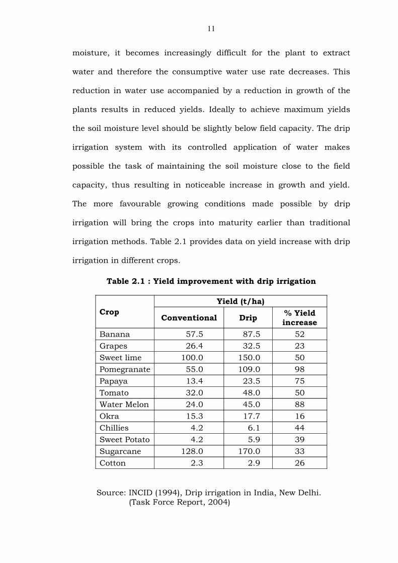
irrigation methods. Table 2.1 provides data on yield increase with drip
irrigation in different crops.
Table 2.1 : Yield improvement with drip irrigation
CropYield (t/ha)
Conventional Drip % Yield increase
Banana 57.5 87.5 52Grapes 26.4 32.5 23Sweet lime 100.0 150.0 50Pomegranate 55.0 109.0 98Papaya 13.4 23.5 75Tomato 32.0 48.0 50Water Melon 24.0 45.0 88Okra 15.3 17.7 16Chillies 4.2 6.1 44Sweet Potato 4.2 5.9 39Sugarcane 128.0 170.0 33Cotton 2.3 2.9 26
Source: INCID (1994), Drip irrigation in India, New Delhi. (Task Force Report, 2004)
11
2.3.2 Water Conservation through increased beneficial use of available water
There is a general agreement that irrigation water requirements
can be less with drip irrigation than with conventional surface and
sprinkler irrigation methods (Aljibury, 1974; Davis, 1975; Shoji, 1977;
Bresler, 1977; Hillel, 1980; Howell et al., 1980). The savings, of
course, depend on the crop, soil, environmental conditions and the
attainable on-farm irrigation efficiency (Table 2.2). Primary reasons
given for the water savings include irrigation of a smaller portion of
the soil volume, decreased direct soil surface evaporation (Dan, 1974),
reduced water uptake by weeds due to dry surfaces between
rows/trees (Lemon, 1956), reduced irrigation runoff from the field (the
dry soil between rows could also store more precipitation), prevention
of runoff from steep hills (Marsh et al., 1975) and particularly for low-
permeability or crusted soils (Kemper and Noonan, 1970) and
controlled deep percolation losses (Rawlins, 1973) especially on sandy
soils (Roth, 1974) below the crop root zone. Sprinkler irrigation is
subject to water loss by wind drift, increased evaporation, or poor
application uniformity, especially with strong winds (Seginer, 1969).
Further the increase in yields combined with water savings results in
higher water use efficiency (WUE) (Table 2.2).
12

Table 2.2 : Water savings & WUE with drip irrigation in various crops
CropYield
increase, %
Water Saving, %
Increase in Water Use
Efficiency, %Banana 52 45 176Chilly 45 63 291Grapes 23 48 136Groundnut 91 36 197Sweet Lime 50 61 289Pomegranate 45 45 167Sugarcane 33 56 204Tomato 50 31 119Water Melon 88 36 195
Source: INCID (1994), Drip irrigation in India, New Delhi. Task Force Report,2004.
2.3.3 Reduced salinity hazards to plants
Considerable evidence exists that waters of higher salinity can
be used with drip irrigation than with other methods without greatly
reducing crop yields. Minimizing the salinity hazard to plants irrigated
by drip irrigation can be attributed to: (i) dilution of the soil solution’s
salt concentration, as a consequence of high frequency the irrigation
used to maintain high soil water contents in the root zone (Bernstein
and Francois, 1975; Rhoades et al., 1974); (ii) elimination of leaf
damage caused by foliar salt absorption with sprinkler irrigation
(Gornat et al., 1973; Bernstein and Francois, 1975); and (iii)
movement of salts beyond the active plant root zone (Patterson and
Wierenga, 1974; Tscheschke et al., 1974).
13
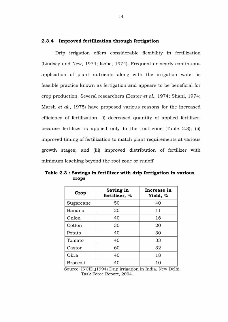
2.3.4 Improved fertilization through fertigation
Drip irrigation offers considerable flexibility in fertilization
(Lindsey and New, 1974; Isobe, 1974). Frequent or nearly continuous
application of plant nutrients along with the irrigation water is
feasible practice known as fertigation and appears to be beneficial for
crop production. Several researchers (Bester et al., 1974; Shani, 1974;
Marsh et al., 1975) have proposed various reasons for the increased
efficiency of fertilization. (i) decreased quantity of applied fertilizer,
because fertilizer is applied only to the root zone (Table 2.3); (ii)
improved timing of fertilization to match plant requirements at various
growth stages; and (iii) improved distribution of fertilizer with
minimum leaching beyond the root zone or runoff.
Table 2.3 : Savings in fertilizer with drip fertigation in various crops
Crop Saving in fertilizer, %
Increase in Yield, %
Sugarcane 50 40Banana 20 11Onion 40 16Cotton 30 20Potato 40 30Tomato 40 33Castor 60 32Okra 40 18Broccoli 40 10
Source: INCID,(1994) Drip irrigation in India, New Delhi. Task Force Report, 2004.
14
However, fertilizers must be completely soluble in water in order
to be distributed evenly through the drip system. Chemicals of low
solubility may precipitate causing blockage of the emitters. There is
usually no problem with nitrogen and potassium compounds (Miller et
al., 1976). Phosphorous is usually added in soluble forms as
orthophosphate, as mono ammonium polyphosphate, phosphoric acid
(Rauschkolb et al., 1976). Microelements may be added in chelate
form.
The drip systems is well suited to the application of herbicides
and soil-borne diseases and pests, since localized application only in
the wetted area results in the chemicals being more effective at lower
concentrations
2.3.5 Reduced operation labour
Labour and operational costs can be reduced by simultaneous
application of water, fertilizer, herbicide, insecticide, fungicide and
other additives through the drip irrigation system (Davis and Nelson,
1970; Sivanappan, 1994; Narayanamoorthy, 2001). Localized dry and
wet patterns facilitate these simultaneous operations. Further drip
irrigation systems can be easily automated where labour is limited &
expensive using simple automation equipment such as electrical,
mechanical or battery operated time clocks that activate pumps and
solenoid valves at selected time during the day.
2.3.6 Maintaining dry foliage
15
Dry foliage retards the incubation and development of many
plant pathogens. Therefore, less frequent pesticide and fungicide
application is required under drip irrigation and the chemicals are not
washed from the leaves by irrigation water. An additional advantage of
dry foliage is the avoidance of leaf burn when irrigating with saline
water (Bernstein and Francois, 1975) and the possibility of using
reclaimed sewage water without leaf and fruit contamination.
Moreover, dry foliage eliminates direct evaporation loss of water from
the canopy, although such evaporation is sometimes desirable for
microclimate modification. Shelhevet et al. (1983) showed a 10%
reduction in water loss due to avoidance of canopy wetting of potato
by drip compared with sprinkler irrigation.
2.4 POTENTIAL DISADVANTAGES OF MICROIRRIGATION
Despite observed successes, several problems have been
encountered in the mechanics of applying water with microirrigation
equipment for some soils, water qualities and environmental
conditions. Some of the more important possible disadvantages of
microirrigation systems as compared to other irrigation methods
include the following:
2.4.1 Emitter clogging
Emitter clogging is considered the most serious problem in drip
irrigation unless preventive measures are taken (Bucks et al., 1977).
Clogging will adversely affect the rate and uniformity of water
application, increase maintenance costs (as it becomes necessary to
16
check, replace or reclaim clogged emitters), and result in crop damage
and decreased yield if not detected and corrected early. Researchers
and equipment manufacturers have chosen to solve this problem
either by developing emitters which may require less maintenance
(Solomon, 1977) or by improving the quality of water before it reaches
the emitters (Nakayama et al., 1978; Bucks et al., 1977). However, all
agree that preventive maintenance (including filtration, chemical
water treatment, flushing dripper lines and field inspection) is
probably the most effective solution to emitter clogging.
2.4.2 Mechanical damage
Damage to drip system is sometimes caused by man
(implements and vandalism) or by animals (birds or mammals making
holes in the laterals while searching for water). This damage may be
partially prevented by covering the laterals and emitters with a
shallow layer of soil, but by doing so, problems of clogging by roots
may occur and furthermore, the performance of the emitters cannot
be easily observed. Trapping, or repelling, the fauna or providing them
with an alternative source of water is sometimes effective. Mechanical
damage may also be induced by annual removal and subsequent
installation of the laterals, by tillage implements or by thermal
expansion and contraction, which may disconnect inline emitters.
2.4.3 Economic limitations
Because equipment requirements are numerous with
microirrigation, initial investments and annual costs may be high. The
17
actual costs will vary considerably depending on the crop, grade of
pipelines, filtration equipment, fertigation equipment and the degree
of automation desired. Generally, the system was found to be
economically viable in commercial field crops, vegetables, flowers,
orchard & fruit crops. Microirrigation systems are generally not
applicable to cereals and millets due to prohibitive initial system
costs.
2.4.4 Operational constraints
High technical skills are required for the proper design and
maintenance of drip irrigation systems. The filtration requirements are
stringent and should be designed according to fluctuations in water
quality. Careful monitoring of the filtration system, the operating
pressures and the emitter flow rates is required. Drip systems have a
limited buffering capacity because of the limited wetted root volume.
Therefore, any malfunction of pumping, filtration, fertilizing or
chlorination equipment or any leak in mains or laterals can have a
disastrous consequence, if not corrected in a timely manner. This is
especially true for a subsurface system, where the emitters are buried
and any failures caused by clogging are difficult to observe and still
more difficult to repair.
2.5 SYSTEM COMPONENTS
Much significant advancement has occurred in the design of
components and microirrigation systems. The basic components of a
microirrigation system can be grouped into three subsystems viz.,
18
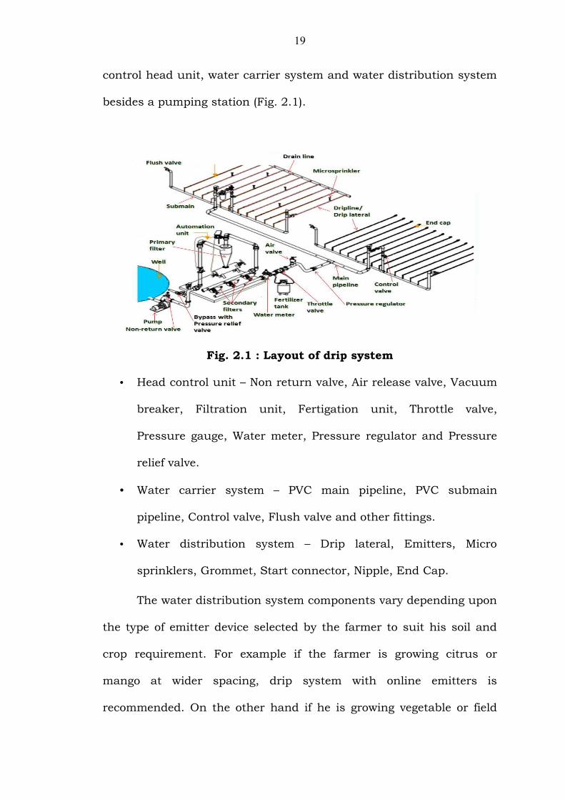
control head unit, water carrier system and water distribution system
besides a pumping station (Fig. 2.1).
Fig. 2.1 : Layout of drip system
• Head control unit – Non return valve, Air release valve, Vacuum
breaker, Filtration unit, Fertigation unit, Throttle valve,
Pressure gauge, Water meter, Pressure regulator and Pressure
relief valve.
• Water carrier system – PVC main pipeline, PVC submain
pipeline, Control valve, Flush valve and other fittings.
• Water distribution system – Drip lateral, Emitters, Micro
sprinklers, Grommet, Start connector, Nipple, End Cap.
The water distribution system components vary depending upon
the type of emitter device selected by the farmer to suit his soil and
crop requirement. For example if the farmer is growing citrus or
mango at wider spacing, drip system with online emitters is
recommended. On the other hand if he is growing vegetable or field
19

crop like sugarcane or cotton crop with narrow spacing, integral
dripline with line source emitters would be appropriate. In fruit crops
with more than 10 years age spray irrigation viz., either micro
sprinkler or micro jets may be advisable in view of adaptability
problems with drip irrigation.
2.5.1 Emitters
Many different emitters have been devised and manufactured
within the last decade. Some of the more distinctive designs are the
short-path, long-path, short-orifice, vortex, pressure-compensating,
self-flushing, perforated single and double - chamber tubing, as well
as porous – tubing emitters (Solomon, 1977). These designs can be
classified into two types, point source and line source. Point – source
systems discharge water from individual or multiple outlets that are
spaced at least 1 m apart. Line – source systems have perforations,
holes, or porous walls in the irrigation tubing that discharge water at
close spacings, or even continuously along a lateral line (Keller and
Karmeli, 1975). Typically, point-source emitters are used for tree
crops, vines, ornamentals and shrubs, whereas line-source emitters
are used for small fruits, vegetables, or other closely spaced row
crops. Better materials and manufacturing have improved extrusion
and molding of point-source emitters. Multilayer bonding and laser
techniques have enhanced the reliability of line-source emitters. A
miscellaneous group of emitters (bubblers, low-head sprayers,
spitters, foggers, etc.) can also be included, since they resemble both a
point – source emitter and a small sprinkler.
20
Hydraulically, most emitter flow regimes can be
characterized by the Reynolds number, Re, defined as
Re = vd/v
Where v is the emitter flow velocity (m/sec), d is the emitter
diameter (m), and v is the Kinematic viscosity (m2/sec). Four flow
regimes are defined as: (1) laminar, Re<2000; (2) unstable,
2000≤Re≤4000;(3) partially turbulent, 4000≤Re≤10,000; and (4) fully
turbulent, 10,000 ≤Re.
Keller and Karmeli (1974, 1975) and Howell and Hiler (1974)
have suggested that the emitter flow function can be given as
q = cHe
Where q is the emitter discharge rate (liters/hr), c is the emitter
discharge coefficient that depends on the choice of units, H is the
emitter pressure head (m), and e is the emitter discharge exponent
that characterizes the flow regime. For fully turbulent flow, e = 0.5; for
partially turbulent flow, 0.5<e<0.7; for the unstable flow regime,
0.7<e<1.0; and for laminar flow e=1.0. Short-orifice emitters are
always fully turbulent, where as long-path or other emitters may vary
in flow characteristics.
Many manufacturers provide standard curves that show
average emitter discharge rates for different operating pressure heads
under laboratory conditions.
2.5.2 Distribution lines and Fitting
21
Distribution lines consist of a network of graduated pipe sizes
starting with a single, large main line followed by smaller submain
and lateral lines. The buried main and submain lines are normally of
rigid polyvinyl chloride (PVC) pipe. They can also consist of lay-flat
PVC pipe (temporary surface lines for row crops), asbestos-cement
pipe (main line for tree crops), or polyethylene (PE) plastic (temporary
surface lines for all crops). Main and submain lines range in diameter
from 4 to 15 cm and should have valved outlets for periodic pipeline
flushing. The submain line may also contain pressure regulators or
flow control valves, manual or automatic control valves, secondary
filters for final filtration or protection against pipeline breakage, or
additional safety devices.
Lateral lines are usually of PE plastic and range in diameter
from 8 to 25 mm, with the 14-mm size being most common. Early
versions of PE tubing developed cracking problems, caused by
polyaxial stress from the insertion of fittings that were larger than the
inside diameter of the lateral, and/or by the thermal or chemical
environment (Shipston, 1976). Stress cracks also developed where
ends of PE lateral were closed off or crimped. Improved PE pipe
extrusion techniques, the use of cross-linking methods and ultraviolet
decomposition inhibitors, the proper sizing of barb fittings and the
development of compression fittings have eliminated most of the
problems. Also, polybutylene is sometimes used in place of PE for
lateral lines to avoid stress cracking. Howell and Barinas (1980) have
measured the pressure losses across emitters and fittings that are
22
inserted in lateral lines and have presented head loss curves for them
in terms of equivalent lengths of pipe as a function of flow rate.
2.5.3 System control, Water measurement and Automation
The main control station for a trickle irrigation system consists
of a pump, a backflow – prevention device, a primary filter, a pressure
regulator (or automatic or mechanical flow control valves), pressure
gauges, a water meter and sometimes automation and chemical
injection equipment. Some of these components will be discussed in
greater detail later in this chapter. The importance of installing a
water measurement device on every trickle system has been too often
overlooked. A water meter is needed to check initial designs, to
manage or schedule irrigations and to monitor possible maintenance
problems. Frequent measurement of the flow rate to various sections
of the field facilitates detection of problems before they become
serious. For example, a gradual decrease in flow rate may indicate a
clogged secondary filter or emitter, whereas a sudden increase in flow
could suggest a break in the distribution lines. Because discharge
rates for trickle emitters are normally low, smaller capacity and less
costly water meters can be used for trickle than for other traditional
irrigation methods.
Trickle systems are readily automated. Single and multistation
timers or controllers and related solenoid valves are easily installed to
eliminate the work of turning water on or off manually. Filter back
washing (Wilson, 1972) and lateral line flushing (Shearer, 1977) for
23

system maintenance can also be automated. Soil moisture sensors
(Austin and Rawlins, 1977; New and Roberts, 1973) can be used to
activate control systems. Sophisticated switching tensiometers were
tested by Wendt et al. (1973). Phene et al. (1973) described the
successful use of a soil matric potential (heat-dissipation) sensor to
automate trickle irrigation systems. Pan evaporation measurements
(Busman and Fangmeier, 1979; Phene and Campbell, 1975) have also
been used with trickle irrigation systems. Mears et al. (1979)
developed a microprocessor based controller for automatic trickle
irrigation. Future trickle irrigation systems will probably use
microprocessors that monitor not only soil moisture, but also
hydraulic pressure, flow rate, chemical injection rate and weather
data.
2.6 SYSTEM DESIGN AND EVALUATION
Before any system is installed, the hydraulic design should be
adequately evaluated and the emission uniformity continually
evaluated for assuring maximum economical and efficient operation.
2.6.1 Hydraulics
The flow regime throughout a trickle irrigation system is
hydraulically steady, spatially varied pipe flow with lateral outflows.
The total discharge in the distribution network (Lateral, sub main and
main lines) decreases with respect to distance from the pump. The
lateral and submain have similar hydraulic characteristics and are
designed to maintain a small pressure variation along the lateral line.
24
The main line is designed in terms of input pressures and minimal
required pressures at any submain line. Trickle design principles are
similar to those developed for sprinkler irrigation systems except that
the flow rates are lower and the number of outlets (sub
mains, laterals and emitters) is larger.
Trickle irrigation distribution lines are normally considered to
be smooth pipes, and either the Darcy – Weisbach or Hazen – Williams
equation can be used to compute friction losses for the pipelines.
The Darcy – Weisbach equation is
Hf = 6.38fLD-5Q2
Where Hf is the pipe friction loss (m), L is the pipe length (m), D is the
inside pipe diameter (mm), Q is the pipe flow rate (liters/hr), and f is a
dimensionless friction factor. An acceleration of gravity of 9.81 m/sec2
was assumed in this equation. Watters and Keller (1978) proposed a
simplified form of Hf = 6.38fLD-5Q2
Hf = 0.465LD-4.75Q1.75
Equation Hf = 0.465LD-4.75Q1.75 incorporates a friction factor estimated
from the Blasius equation for smooth pipes with a water temperature
of 200C (v=1.0×10⁻⁶ m2/sec).
The empirically developed Hazen – Williams equation is
Hf = 0.628 LD-4.865 [(100Q)/C]1.852
Where C is a dimensionless pipe roughness factor. Equation Hf =
0.628 LD-4.865 [(100Q)/C]1.852 is widely used because of its simplicity,
although it has no correction for viscosity. Care should be taken in
25

selecting the C values. Hughes and Jeppson (1978) showed that the
selection of the proper C for Hf = 0.628 LD-4.865 [(100Q)/C]1.852 obviously
depends on the Reynolds number Re; and Howell et al. (1980)
suggested that the best C values for trickle irrigation systems were C =
130 for 14-15 mm pipe, C = 140 for 18-19 mm pipe, and C = 150 for
25-27-mm pipe. A low estimate of C will overestimate the friction loss,
whereas a high estimate will result in more conservative friction loss
for design purposes.
Pressure variations along a trickle irrigation line are primarily
due to friction and slope. Numerous publications and books describe
the basic principles, procedures and details for proper sizing of trickle
irrigation pipelines (Baars, 1976; Keller and Karmeli, 1975; Howell et
al., 1980; Wu et al., 1979) present design charts for lateral, submain
and main lines for different field slopes, shapes and pipe sizes along
with design examples. Some of the more recent developments in
trickle irrigation hydraulics are as follows; Bresler (1978) introduced a
design procedure using both soil water flow models and hydraulics;
Keller and Karmeli (1974) developed a compact “polyplot” design
technique for tapered submains; Braud and Soom (1981) introduced
design equations including both emitter and pipeline hydraulics; and
Wu and Gitlin (1981) developed double – inlet and inflow – outflow
systems using network design principles.
Steady and nonsteady infiltration models (Bresler, 1978) were
used to calculate the desired spacing between emitters as a function
of their discharge, soil hydraulic properties and crop sensitivity to
26
water stress. Ideally, trickle irrigation systems should be designed
with emitter spacings and discharge rates such that small depression
ponds of less than 0.2 m in diameter will develop beneath or around
an emitter without runoff or down slope channelization.
Varying the size of submain lines gives the designer an
opportunity to reduce costs, investigate alternate designs and develop
site-specific designs (Keller and Karmeli, 1974). Design equations in a
form that include emitter characteristics (emitter exponent, emitter
variability, etc.) as well as lateral line hydraulics (length, diameter,
land slope, etc.) are being developed for analysis by programmable
digital calculators (Braud and Soom, 1981). Multiple-inlet systems
can be designed with a combination of double-inlet (inflow from both
ends of a lateral line from two submains) and inflow – outflow (inflow
from a submain to a lateral line with out flow to the next submain
line) in a total network design (Wu and Gitlin, 1981). This type of
design can permit any length of lateral in varying field shapes and
terrain. As a general recommendation, lateral lines should seldom be
more than 300 m long and should be laid down slope for less than 5%
slopes. If the slope exceeds 5%, laterals should be installed along the
field contour, pressure compensating emitters specified, or pressure
control devices installed.
Uniformity of water application along lateral lines can also be
improved by changing emitter sizes (Myers and Bucks, 1972). The
fixed emitter characteristics are normally adequate from a hydraulic
standpoint for level terrain.
27
2.6.2 Emission Uniformity
Several methods have been proposed for assessing the
uniformity of water application in irrigation systems. The term
emission uniformity has generally been used to describe the emitter
flow variation for a trickle irrigation unit or subunit. Emission
uniformity can be a function of: (1) hydraulic variation caused by
evaluation changes and friction losses along distribution lines and (2)
emitter discharge variation at a given operating pressure caused by
manufacturing variability, clogging water temperature changes, and
aging. Presently, no design equation has been developed that includes
all the factors which might affect emission uniformity.
28

![Second Installment (SCSP Category) - DACaps.dac.gov.in/microirrigation/Archive/03032016Sikkim.pdf · Management in 2014-15] ... The Secretary Horticulture & Cash Crops Development](https://img.pdfslide.us/doc/110x75/5ab8609e7f8b9ad5338cc11c/second-installment-scsp-category-in-2014-15-the-secretary-horticulture.jpg)