Embed Size (px)
Citation preview
2. (Lab #6) Ohm’s Law, Series and Parallel
Connection
Objective:
The objectives of this experiment are:
1) to understand and use Ohm’s Law
2) to learn, understand, and use resistors connected in series and parallel
3) to learn the basic concepts and relationships of current and voltage measurements in DC
circuits containing resistors wired in series and parallel
4) to learn the relationships of the total resistance of resistors connected in series and parallel
5) to learn to use ammeters, voltmeters, ohmmeters, and multimeters to properly measure
voltages, currents, and resistances.
Introduction:
Most common household electrical circuits are made of many devices connected in parallel.
Each device is hooked to the power source in parallel with all the other devices, each connected to
the same voltage source and availing itself of the same voltage. Each device has its own
characteristic resistance, and therefore each draws from the source a different amount of current,
depending on its resistive value. While the voltage being accessed is nearly the same for all devices,
the amount of current drawn from the source increases as each device draws its respective current
based on its resistance. As a result as more and more devices are connected in parallel, the total
amount of current drawn from the source increases. It thus has the effect of causing the resistance
to decrease with each additional resistance added. Additional devices added to a circuit, require
additional current from the source until something is overloaded. More current is required beyond
that which can be supplied by the source or carried by the conductors without burning up.
Series circuits are not as common, except for old time Christmas tree lights that are a
challenge to fix when one unknown bulb has burned out and all the rest fail to work.
However, all wires that make connections and the connections themselves qualify as series
resistance. Wires have resistance that depend on wire size, length, and type of material. Wires add
series resistance to circuits, just as good and bad connections add also. In order to fully understand
electrical circuits and their behavior, one must first understand Ohm’s Law and the principles
regarding resistors in series and parallel circuits.
Background Theory:
1) Ohm’s Law
Ohm’s Law is the relationship between the current I flowing through a resistance R and
the potential drop across it V. The current is directly proportional to the potential difference across
the resistance and is inversely proportional to the resistance,
𝐼 =𝑉
𝑅 (6 − 1)
As an alternative, Ohm’s Law may be stated as: The potential difference V across a
resistance is directly proportional to the current I flowing through the resistance and the resistance
R, or
𝑉 = 𝐼 × 𝑅 (6 − 2)
Ohm’s Law can be rearranged to define the resistance R so that
𝑅 =𝑉
𝐼 (6 − 3)
If the potential difference across the resistance is measured in volts (V) and the current
flowing through the resistance is measured in amperes (A), then the resistance values will be in
units of ohms.
2) Resistors in Series
Figure (6-1) shows 3 resistors, R1, R2, and R3, connected in series in a closed circuit
powered by a single battery or Emf source. In this circuit the current supplied by the battery flows
through each resistor, with the current in each resistor being the same. If the current supplied by
the battery is IT, the current in each resistor is 𝐼1, 𝐼2, and𝐼3, and they are all one and the same, then
𝐼𝑇 = 𝐼1 = 𝐼2 = 𝐼3 (6 − 4)
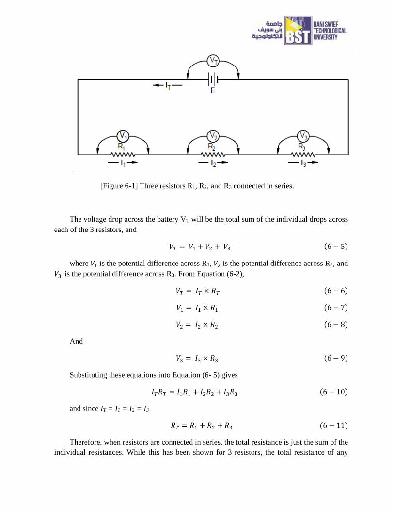
[Figure 6-1] Three resistors R1, R2, and R3 connected in series.
The voltage drop across the battery VT will be the total sum of the individual drops across
each of the 3 resistors, and
𝑉𝑇 = 𝑉1 + 𝑉2 + 𝑉3 (6 − 5)
where 𝑉1 is the potential difference across R1, 𝑉2 is the potential difference across R2, and
𝑉3 is the potential difference across R3. From Equation (6-2),
𝑉𝑇 = 𝐼𝑇 × 𝑅𝑇 (6 − 6)
𝑉1 = 𝐼1 × 𝑅1 (6 − 7)
𝑉2 = 𝐼2 × 𝑅2 (6 − 8)
And
𝑉3 = 𝐼3 × 𝑅3 (6 − 9)
Substituting these equations into Equation (6- 5) gives
𝐼𝑇𝑅𝑇 = 𝐼1𝑅1 + 𝐼2𝑅2 + 𝐼3𝑅3 (6 − 10)
and since IT = I1 = I2 = I3
𝑅𝑇 = 𝑅1 + 𝑅2 + 𝑅3 (6 − 11)
Therefore, when resistors are connected in series, the total resistance is just the sum of the
individual resistances. While this has been shown for 3 resistors, the total resistance of any
number N (N≥2) of resistors connected in series, end to end, can be found using the same general
procedure. Therefore for resistors connected in series
𝑅𝑇 = ∑ 𝑅𝑖
𝑁
𝑖=1
(6 − 12)
3) Resistors in Parallel
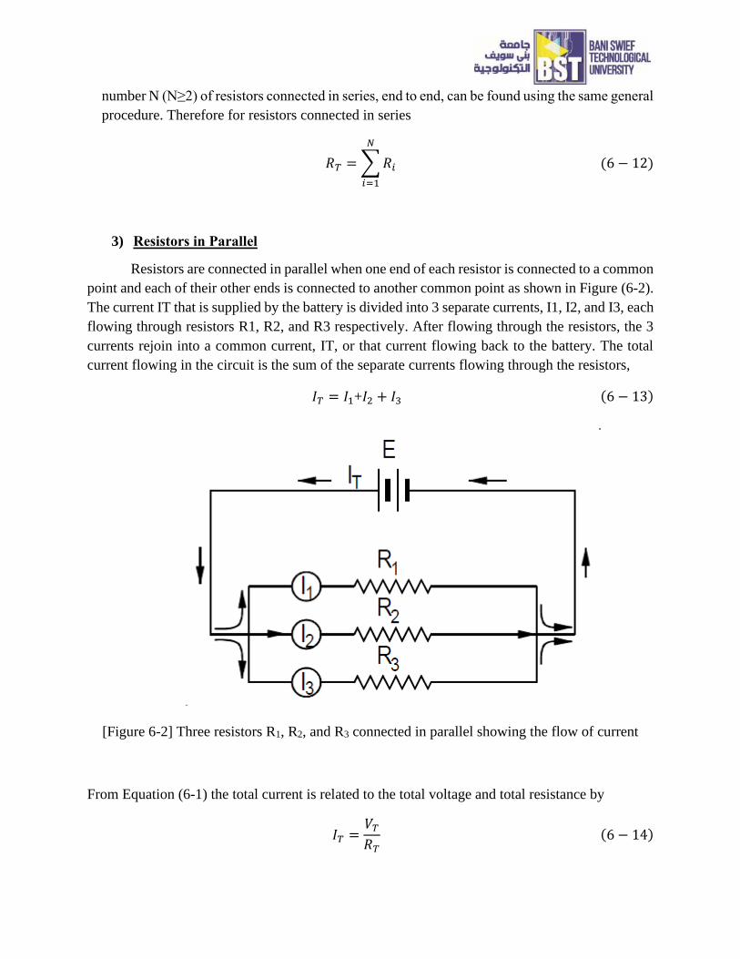
Resistors are connected in parallel when one end of each resistor is connected to a common
point and each of their other ends is connected to another common point as shown in Figure (6-2).
The current IT that is supplied by the battery is divided into 3 separate currents, I1, I2, and I3, each
flowing through resistors R1, R2, and R3 respectively. After flowing through the resistors, the 3
currents rejoin into a common current, IT, or that current flowing back to the battery. The total
current flowing in the circuit is the sum of the separate currents flowing through the resistors,
𝐼𝑇 = 𝐼1+𝐼2 + 𝐼3 (6 − 13)
[Figure 6-2] Three resistors R1, R2, and R3 connected in parallel showing the flow of current
From Equation (6-1) the total current is related to the total voltage and total resistance by
𝐼𝑇 =𝑉𝑇
𝑅𝑇 (6 − 14)
and the current, potential difference, and resistance of each separate resistor is given by
𝐼1 =𝑉1
𝑅1 (6 − 15)
𝐼2 =𝑉2
𝑅2 (6 − 16)
And
𝐼3 =𝑉3
𝑅3 (6 − 17)
Substituting these equations into Equation (6-13)
𝑉𝑇
𝑅𝑇=
𝑉1
𝑅1+
𝑉2
𝑅2+
𝑉3
𝑅3 (6 − 18)
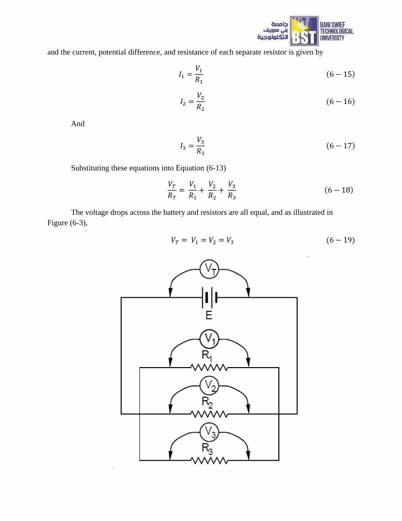
The voltage drops across the battery and resistors are all equal, and as illustrated in
Figure (6-3),
𝑉𝑇 = 𝑉1 = 𝑉2 = 𝑉3 (6 − 19)
[Figure 6-3] Three resistors R1, R2, and R3 connected in parallel showing the potential differences
all being equal.
Since all the potentials are equal Equation (6-18) reduces to
1
𝑅𝑇=
1
𝑅1+
1
𝑅2+
1
𝑅3 (6 − 20)
which is the equation for the total resistance of 3 resistors connected in parallel. As was
the case for series resistors, the total resistance of any number N (N≥2) of resistors connected in
parallel can be found using the same general procedure and will result in the relationship
1
𝑅𝑇= ∑
1
𝑅𝑖
𝑁
𝑖=1
(6 − 21)
In circuits with combinations of resistors in series and parallel, the total resistance can be
found by breaking the circuit down into its simplest unit consisting of either resistor in series or
parallel and then adding its total resistance back into the next simplest unit and finding its total
resistance, and so on until the entire circuit has been reconstructed.
Tasks for the (Lab #6): Ohm’s Law, Series and Parallel Connection
1) Applying Ohm’s Law practically
Ohm’s Law circuit
Equipment
(1) Adjustable DC Power Supply
(2) Digital Multimeter
(3) 1 kΩ resistor
(4) 6.8 kΩ resistor
(5) 33 kΩ resistor
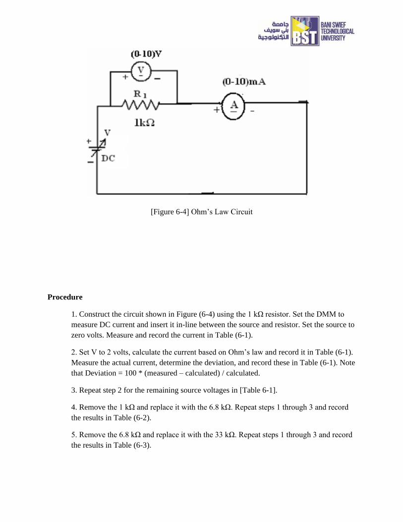
[Figure 6-4] Ohm’s Law Circuit
Procedure
1. Construct the circuit shown in Figure (6-4) using the 1 kΩ resistor. Set the DMM to
measure DC current and insert it in-line between the source and resistor. Set the source to
zero volts. Measure and record the current in Table (6-1).
2. Set V to 2 volts, calculate the current based on Ohm’s law and record it in Table (6-1).
Measure the actual current, determine the deviation, and record these in Table (6-1). Note
that Deviation = 100 * (measured – calculated) / calculated.
3. Repeat step 2 for the remaining source voltages in [Table 6-1].
4. Remove the 1 kΩ and replace it with the 6.8 kΩ. Repeat steps 1 through 3 and record
the results in Table (6-2).
5. Remove the 6.8 kΩ and replace it with the 33 kΩ. Repeat steps 1 through 3 and record
the results in Table (6-3).
6. Using the measured currents from Tables (6-1), (6-2), and (6-3), create a plot of
current versus voltage. Plot all three curves on the same graph. Voltage is the horizontal
axis and current is the vertical axis.
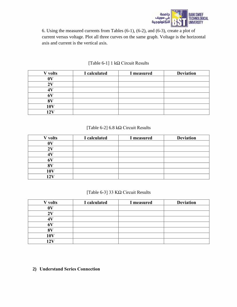
[Table 6-1] 1 kΩ Circuit Results
V volts I calculated I measured Deviation
0V
2V
4V
6V
8V
10V
12V
[Table 6-2] 6.8 kΩ Circuit Results
V volts I calculated I measured Deviation
0V
2V
4V
6V
8V
10V
12V
[Table 6-3] 33 KΩ Circuit Results
V volts I calculated I measured Deviation
0V
2V
4V
6V
8V
10V
12V
2) Understand Series Connection
Series Connection circuit
Equipment and Components
(1) Adjustable DC Power Supply
(2) Digital Multimeter
(3) Resistors :1 kΩ, 2.2 kΩ, 3.3 kΩ and 6.8 kΩ
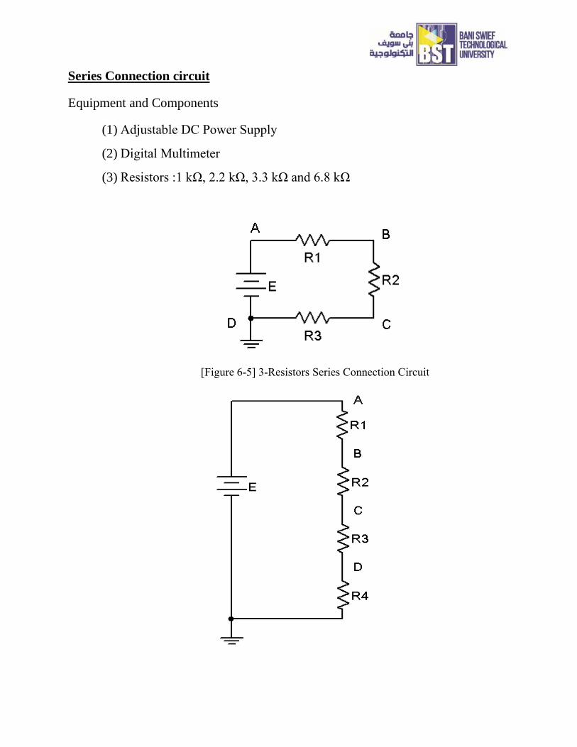
[Figure 6-5] 3-Resistors Series Connection Circuit
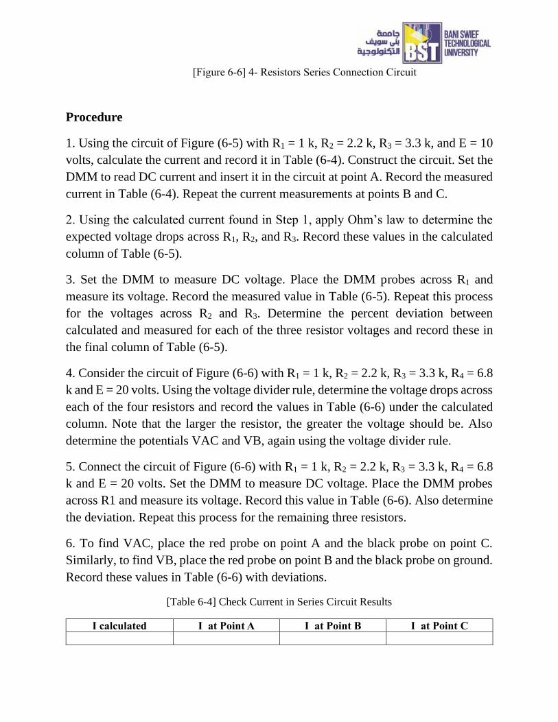
[Figure 6-6] 4- Resistors Series Connection Circuit
Procedure
1. Using the circuit of Figure (6-5) with R1 = 1 k, R2 = 2.2 k, R3 = 3.3 k, and E = 10
volts, calculate the current and record it in Table (6-4). Construct the circuit. Set the
DMM to read DC current and insert it in the circuit at point A. Record the measured
current in Table (6-4). Repeat the current measurements at points B and C.
2. Using the calculated current found in Step 1, apply Ohm’s law to determine the
expected voltage drops across R1, R2, and R3. Record these values in the calculated
column of Table (6-5).
3. Set the DMM to measure DC voltage. Place the DMM probes across R1 and
measure its voltage. Record the measured value in Table (6-5). Repeat this process
for the voltages across R2 and R3. Determine the percent deviation between
calculated and measured for each of the three resistor voltages and record these in
the final column of Table (6-5).
4. Consider the circuit of Figure (6-6) with R1 = 1 k, R2 = 2.2 k, R3 = 3.3 k, R4 = 6.8
k and E = 20 volts. Using the voltage divider rule, determine the voltage drops across
each of the four resistors and record the values in Table (6-6) under the calculated
column. Note that the larger the resistor, the greater the voltage should be. Also
determine the potentials VAC and VB, again using the voltage divider rule.
5. Connect the circuit of Figure (6-6) with R1 = 1 k, R2 = 2.2 k, R3 = 3.3 k, R4 = 6.8
k and E = 20 volts. Set the DMM to measure DC voltage. Place the DMM probes
across R1 and measure its voltage. Record this value in Table (6-6). Also determine
the deviation. Repeat this process for the remaining three resistors.
6. To find VAC, place the red probe on point A and the black probe on point C.
Similarly, to find VB, place the red probe on point B and the black probe on ground.
Record these values in Table (6-6) with deviations.
[Table 6-4] Check Current in Series Circuit Results
I calculated I at Point A I at Point B I at Point C
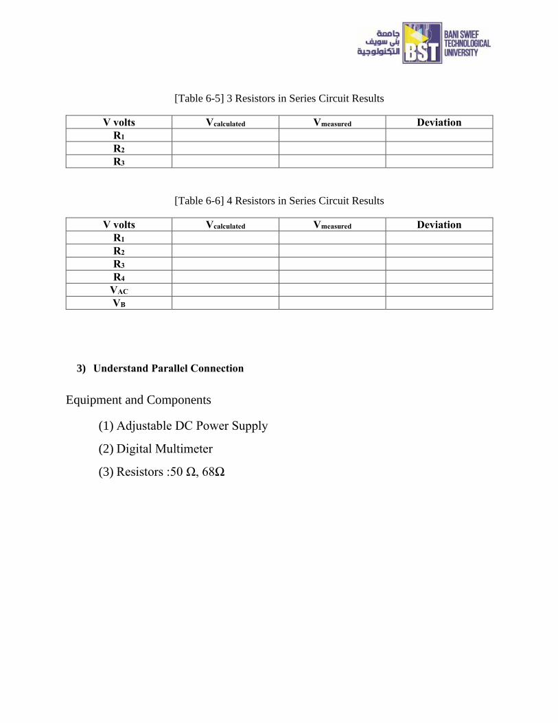
[Table 6-5] 3 Resistors in Series Circuit Results
V volts Vcalculated Vmeasured Deviation
R1
R2
R3
[Table 6-6] 4 Resistors in Series Circuit Results
V volts Vcalculated Vmeasured Deviation
R1
R2
R3
R4
VAC
VB
3) Understand Parallel Connection
Equipment and Components
(1) Adjustable DC Power Supply
(2) Digital Multimeter
(3) Resistors :50 Ω, 68Ω
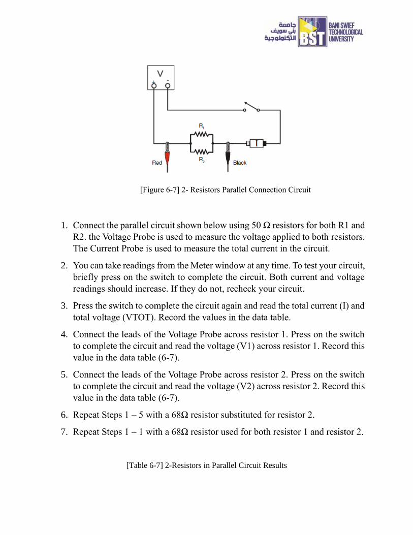
[Figure 6-7] 2- Resistors Parallel Connection Circuit
1. Connect the parallel circuit shown below using 50 Ω resistors for both R1 and
R2. the Voltage Probe is used to measure the voltage applied to both resistors.
The Current Probe is used to measure the total current in the circuit.
2. You can take readings from the Meter window at any time. To test your circuit,
briefly press on the switch to complete the circuit. Both current and voltage
readings should increase. If they do not, recheck your circuit.
3. Press the switch to complete the circuit again and read the total current (I) and
total voltage (VTOT). Record the values in the data table.
4. Connect the leads of the Voltage Probe across resistor 1. Press on the switch
to complete the circuit and read the voltage (V1) across resistor 1. Record this
value in the data table (6-7).
5. Connect the leads of the Voltage Probe across resistor 2. Press on the switch
to complete the circuit and read the voltage (V2) across resistor 2. Record this
value in the data table (6-7).
6. Repeat Steps 1 – 5 with a 68Ω resistor substituted for resistor 2.
7. Repeat Steps 1 – 1 with a 68Ω resistor used for both resistor 1 and resistor 2.
[Table 6-7] 2-Resistors in Parallel Circuit Results
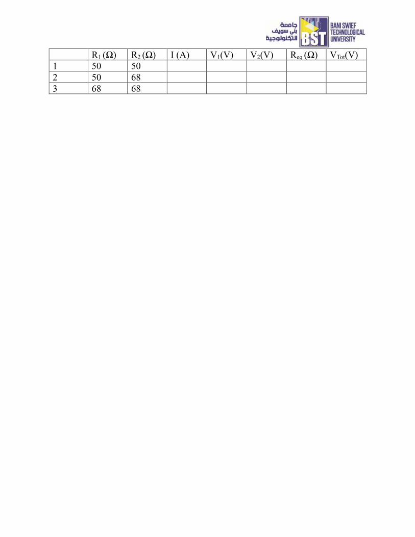
R1 (Ω) R2 (Ω) I (A) V1(V) V2(V) Req (Ω) VTot(V)
1 50 50
2 50 68
3 68 68