Embed Size (px)
Citation preview
2: INSTALLATION MANUAL
NV40LT/NV30LTTRANSMITTER
Document ID: NHB-NV30LT-NV40LT-INSVersion: 4.0 Issue Date: 2018-02-26Status: Standard
Making Digital Radio Work

VERSION 4.0 2018-02-26 PAGE III
NV40LT/NV30LT INSTALLATION MANUAL
Contact Information
Nautel Limited10089 Peggy’s Cove RoadHackett’s Cove, NS Canada B3Z 3J4
Toll Free: +1.877.6NAUTEL (662.8835) (Canada & USA only) or
Phone: +1.902.823.3900 orFax: +1.902.823.3183
Nautel Inc. 201 Target Industrial Circle Bangor, Maine USA 04401
Phone: +1.207.947.8200 Fax: +1.207.947.3693
Customer Service (24-hour support) +1.877.628.8353 (Canada & USA only)+1.902.823.5100 (International)
Email: [email protected]: www.nautel.com
The comparisons and other information provided in this document have been prepared in good faith based on publicly available information. For verification of materials, the reader is encouraged to consult the respective manufacturer's most recent publication on the official website or through contact with Customer Service.
© Copyright 2018 NAUTEL. All rights reserved.


NV40LT/NV30LT INSTALLATION MANUAL TABLE OF CONTENTS
VERSION 4.0 2018-02-26 PAGE 2.V
CONTENTS
Contact Information 2.iii
RELEASE CONTROL RECORD 2.vii
Preparing for installation 2.1.1
Unpacking and Positioning 2.2.1
Installing Options 2.3.1
Upgrading to Dual Exciter 2.3.2Installing the UPS Interface 2.3.3Installing the Orban Inside Card 2.3.4
Connecting to Station Reference Ground 2.4.1
Connecting Ac Power 2.5.1
Installing the RF Feed Cable 2.6.1
Installing Program Inputs 2.7.1
Planning Complete? 2.7.1Routing Cables 2.7.1
Installing Control/Monitor Wiring 2.8.1
Planning Complete? 2.8.1Routing Cables 2.8.1
NV40LT/NV30LT INSTALLATION MANUAL TABLE OF CONTENTS
PAGE 2.VI VERSION 4.0 2018-02-26
Commissioning 2.9.1
Pre-Commissioning Tasks 2.9.1Commissioning 2.9.2Going On-Air 2.9.5Network Setup 2.9.6Changing the OS Password 2.9.8
Parts and Tools 2.10.1
Contacting Nautel 2.10.1Parts Supplied by Nautel 2.10.2Parts Not Supplied by Nautel 2.10.2Parts Ordering 2.10.2Module Exchange Program 2.10.3Tools for Installation 2.10.3
Pre-Installation / Installation Assistance 2.11.1
Pre-Installation Consulting 2.11.1Installation and Commissioning Service 2.11.1Online Documentation 2.11.2On-Site Support 2.11.3Training 2.11.3Standard Warranty 2.11.4Extended Warranties 2.11.7
List of terms 2.12.1
NV40LT/NV30LT INSTALLATION MANUAL
VERSION 4.0 2018-02-26 PAGE 2.VII
Release Control Record
ISSUE DATE REASON
4.0 2018-02-26 Release 4 of NV40LT/NV30LT (NARF75C/01). Supports software version GV SW 4.4

NV40LT/NV30LT INSTALLATION MANUAL
PAGE 2.VIII VERSION 4.0 2018-02-26
NV40LT/NV30LT INSTALLATION MANUAL PREPARING FOR INSTALLATION
VERSION 4.0 2018-02-26 PAGE 2.1.1
SECTION 2.1: PREPARING FOR INSTALLATION
Before installing your NV40LT/NV30LT transmitter, perform the following steps:
1. Ensure that you have performed the pre-installation tasks described in the NV40LT/NV30LT Pre-installation Manual.
2. Make sure that you received all the components. Check your packing list.
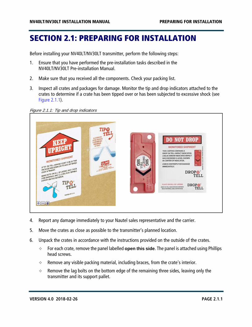
3. Inspect all crates and packages for damage. Monitor the tip and drop indicators attached to the crates to determine if a crate has been tipped over or has been subjected to excessive shock (see Figure 2.1.1).
Figure 2.1.1: Tip and drop indicators
4. Report any damage immediately to your Nautel sales representative and the carrier.
5. Move the crates as close as possible to the transmitter’s planned location.
6. Unpack the crates in accordance with the instructions provided on the outside of the crates.
For each crate, remove the panel labelled open this side. The panel is attached using Phillips head screws.
Remove any visible packing material, including braces, from the crate's interior.
Remove the lag bolts on the bottom edge of the remaining three sides, leaving only the transmitter and its support pallet.
NV40LT/NV30LT INSTALLATION MANUAL PREPARING FOR INSTALLATION
PAGE 2.1.2 VERSION 4.0 2018-02-26
7. Review any assembly notes or instructions contained inside the transmitter crates. (For sites requiring custom configurations, the instructions provided with the transmitter replace the instructions provided here.)
8. Assemble your parts and tools. For a list of required tools, see “Parts and Tools” on page 2.10.1.
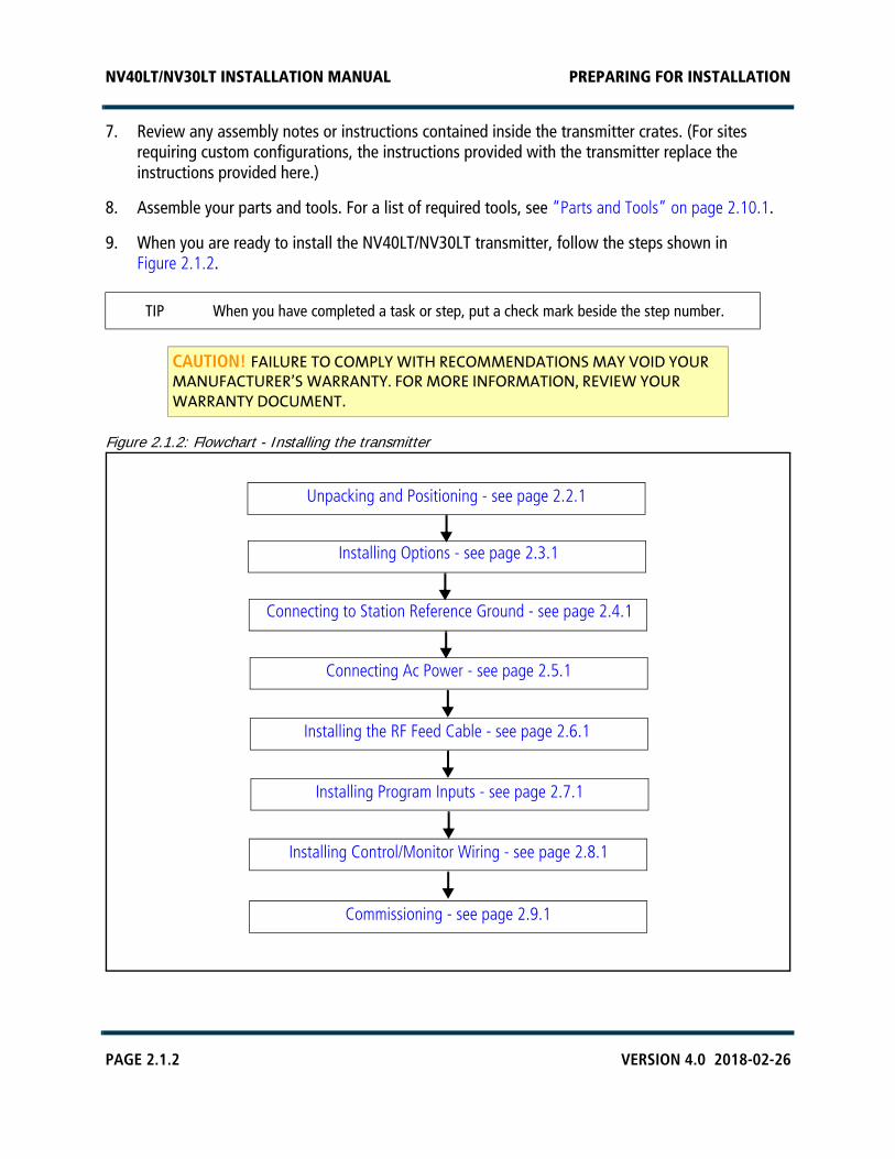
9. When you are ready to install the NV40LT/NV30LT transmitter, follow the steps shown in Figure 2.1.2.
Figure 2.1.2: Flowchart - Installing the transmitter
TIP When you have completed a task or step, put a check mark beside the step number.
CAUTION! FAILURE TO COMPLY WITH RECOMMENDATIONS MAY VOID YOUR MANUFACTURER’S WARRANTY. FOR MORE INFORMATION, REVIEW YOUR WARRANTY DOCUMENT.
Unpacking and Positioning - see page 2.2.1
Connecting to Station Reference Ground - see page 2.4.1
Installing Control/Monitor Wiring - see page 2.8.1
Commissioning - see page 2.9.1
Connecting Ac Power - see page 2.5.1
Installing Program Inputs - see page 2.7.1
Installing the RF Feed Cable - see page 2.6.1
Installing Options - see page 2.3.1
NV40LT/NV30LT INSTALLATION MANUAL UNPACKING AND POSITIONING
VERSION 4.0 2018-02-26 PAGE 2.2.1
SECTION 2.2: UNPACKING AND POSITIONING
To install an NV40LT/NV30LT transmitter, perform the following tasks:
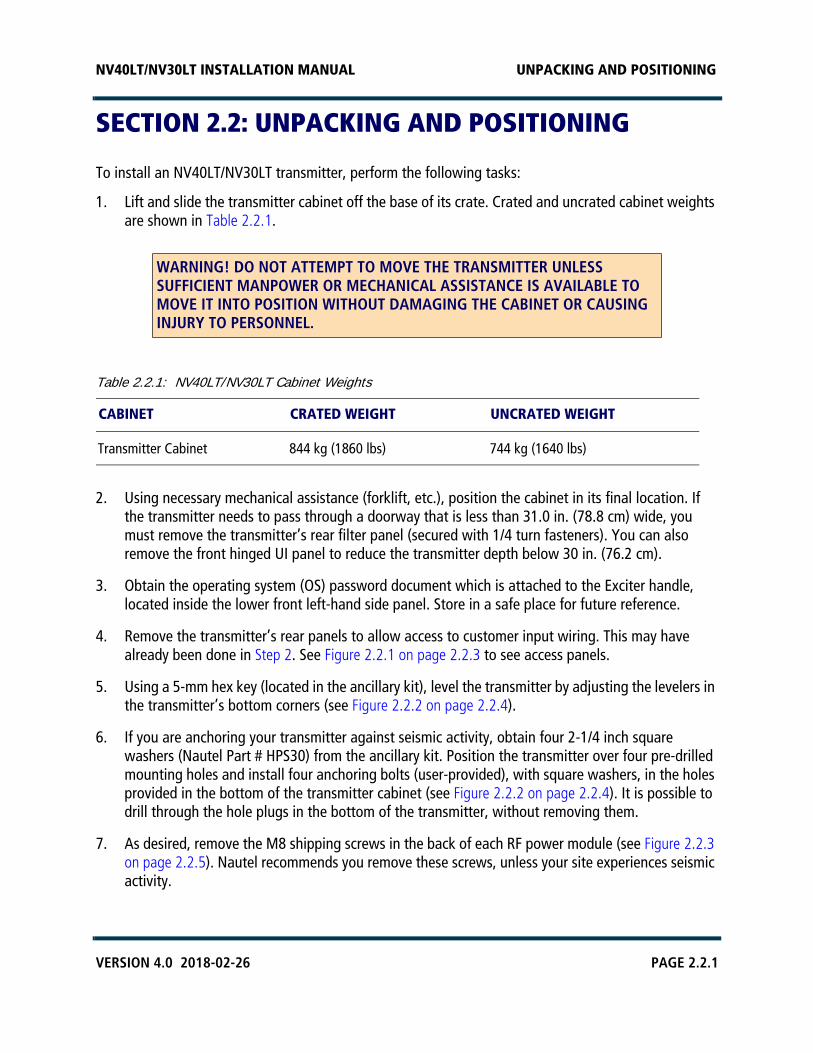
1. Lift and slide the transmitter cabinet off the base of its crate. Crated and uncrated cabinet weights are shown in Table 2.2.1.
Table 2.2.1: NV40LT/NV30LT Cabinet Weights
2. Using necessary mechanical assistance (forklift, etc.), position the cabinet in its final location. If the transmitter needs to pass through a doorway that is less than 31.0 in. (78.8 cm) wide, you must remove the transmitter’s rear filter panel (secured with 1/4 turn fasteners). You can also remove the front hinged UI panel to reduce the transmitter depth below 30 in. (76.2 cm).
3. Obtain the operating system (OS) password document which is attached to the Exciter handle, located inside the lower front left-hand side panel. Store in a safe place for future reference.
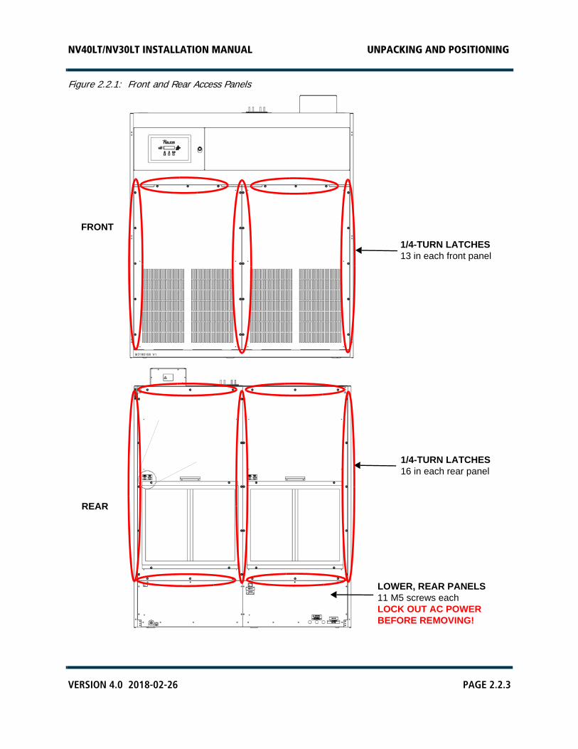
4. Remove the transmitter’s rear panels to allow access to customer input wiring. This may have already been done in Step 2. See Figure 2.2.1 on page 2.2.3 to see access panels.
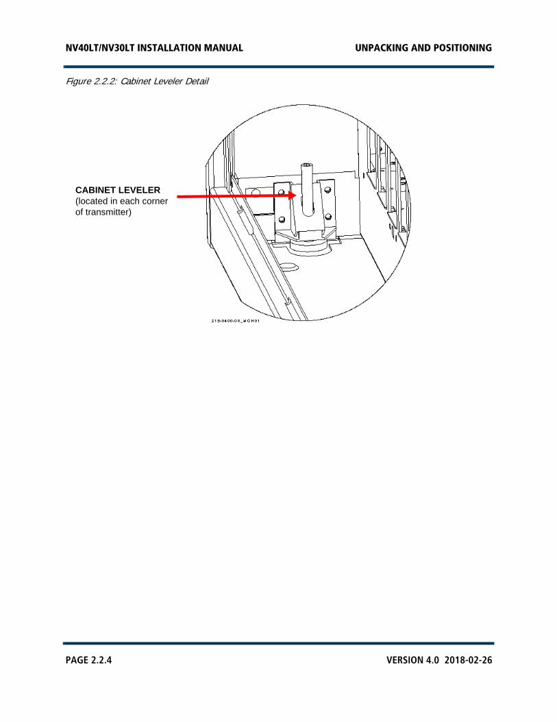
5. Using a 5-mm hex key (located in the ancillary kit), level the transmitter by adjusting the levelers in the transmitter’s bottom corners (see Figure 2.2.2 on page 2.2.4).
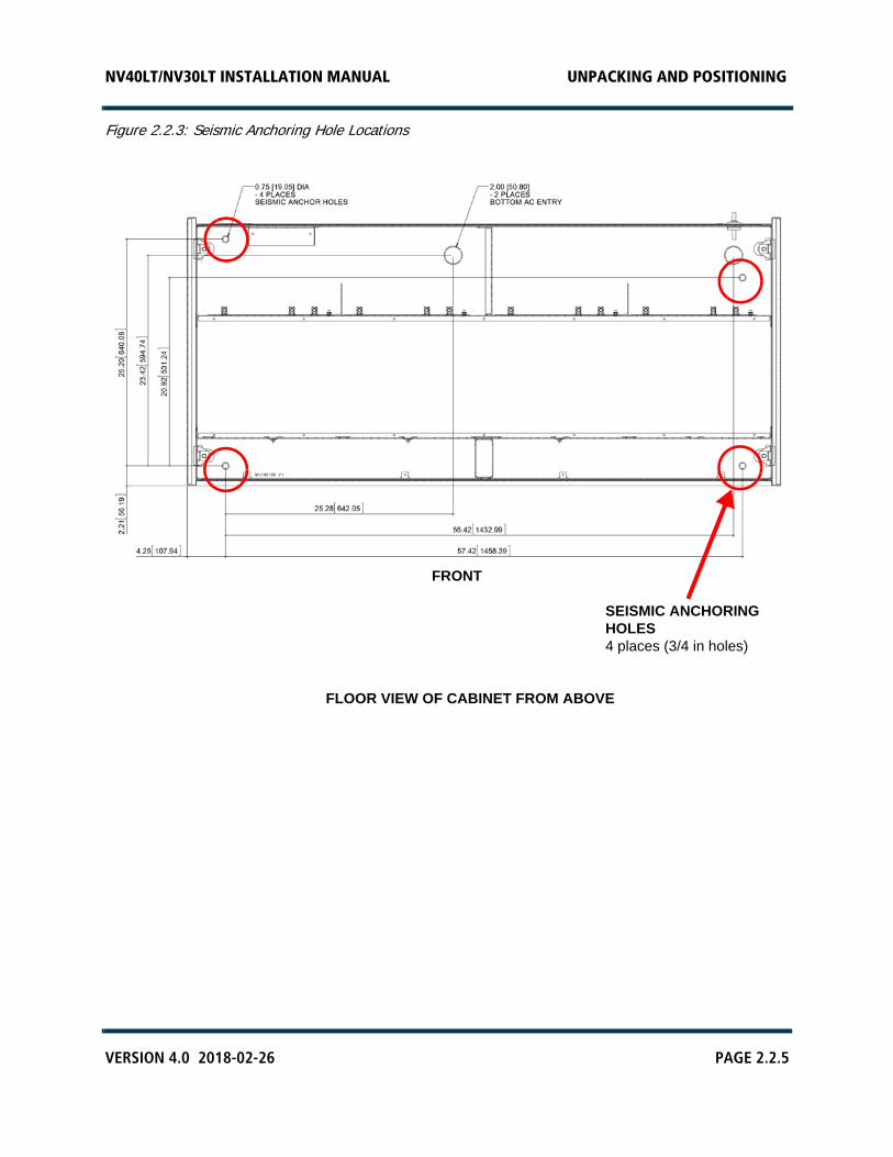
6. If you are anchoring your transmitter against seismic activity, obtain four 2-1/4 inch square washers (Nautel Part # HPS30) from the ancillary kit. Position the transmitter over four pre-drilled mounting holes and install four anchoring bolts (user-provided), with square washers, in the holes provided in the bottom of the transmitter cabinet (see Figure 2.2.2 on page 2.2.4). It is possible to drill through the hole plugs in the bottom of the transmitter, without removing them.
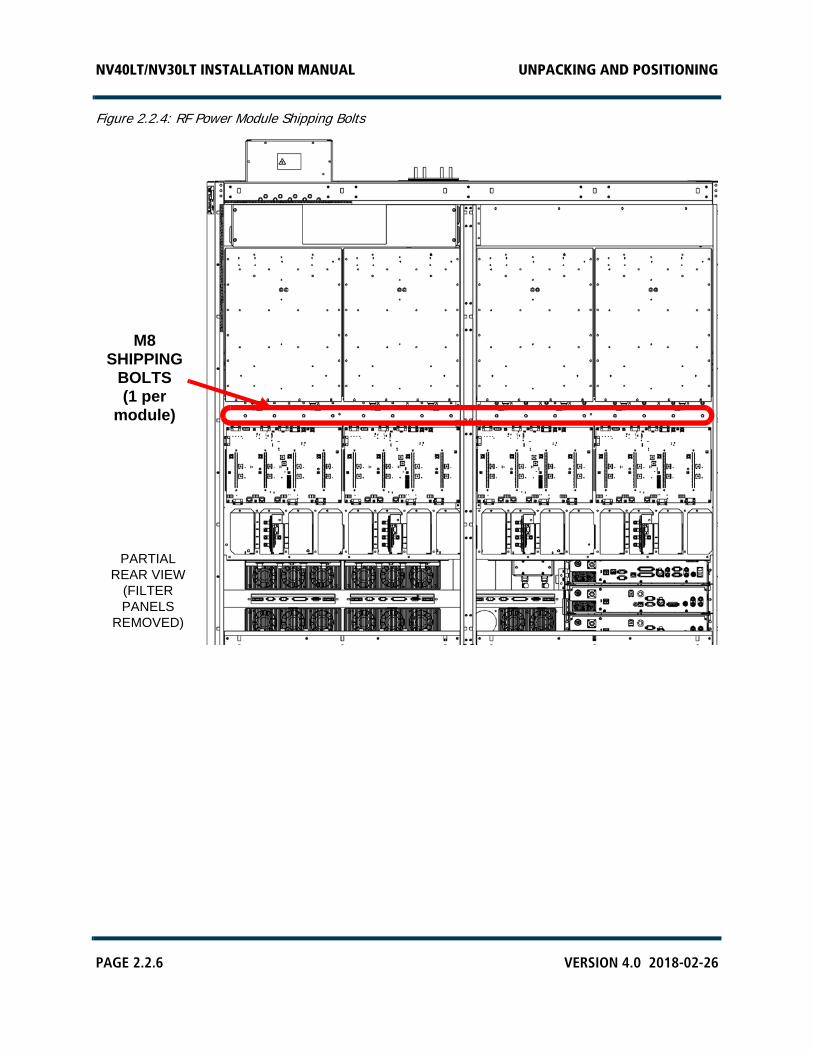
7. As desired, remove the M8 shipping screws in the back of each RF power module (see Figure 2.2.3 on page 2.2.5). Nautel recommends you remove these screws, unless your site experiences seismic activity.
WARNING! DO NOT ATTEMPT TO MOVE THE TRANSMITTER UNLESS SUFFICIENT MANPOWER OR MECHANICAL ASSISTANCE IS AVAILABLE TO MOVE IT INTO POSITION WITHOUT DAMAGING THE CABINET OR CAUSING INJURY TO PERSONNEL.
CABINET CRATED WEIGHT UNCRATED WEIGHT
Transmitter Cabinet 844 kg (1860 lbs) 744 kg (1640 lbs)
NV40LT/NV30LT INSTALLATION MANUAL UNPACKING AND POSITIONING
PAGE 2.2.2 VERSION 4.0 2018-02-26
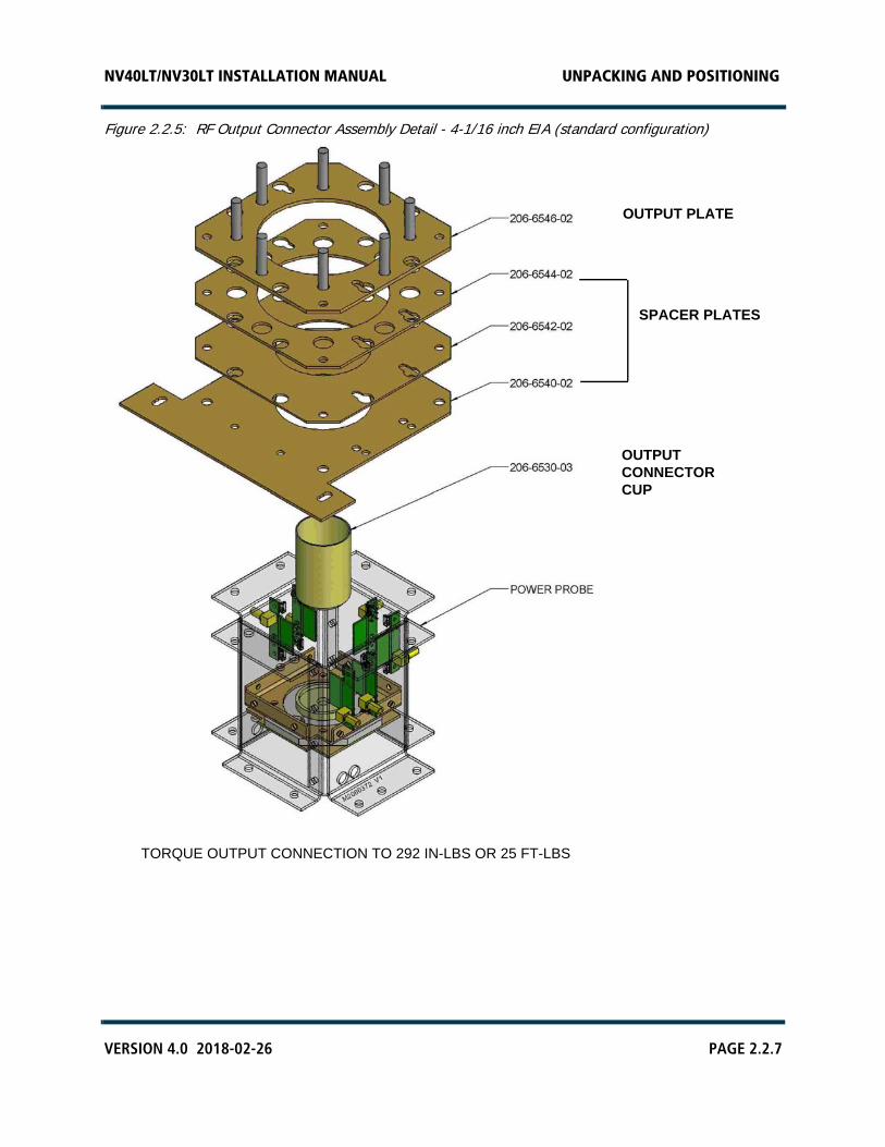
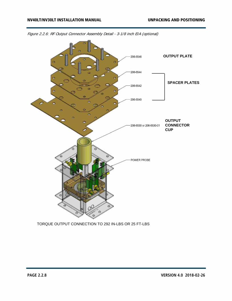
8. Install the RF output connector, which was partially disassembled for shipment, as follows (see Figure 2.2.4 on page 2.2.6 or Figure 2.2.6 on page 2.2.8, as applicable):
NOTE: The RF output connector was factory configured prior to shipping for the desired EIA connector (4-1/16 inch or 3-1/8 inch).
Remove the output cover packing plate from the RF output connector on top of the transmitter. The packing plate - along with three spacer plates - is secured using four M6 screws. Remove only the packing plate, leave the spacer plates in place and retain the screws.
Obtain the “Output Stud Plate”, which was tyrapped in the rear of the transmitter. Using the M6 screws retained above, install the output stud plate on top of the spacer plates. Firmly tighten M6 hardware. Note that the output stud plate’s studs contain the necessary securing hardware (nuts, flat washers and split washers) to connect the RF output to a dummy load or the antenna system in Section 2.9, “Commissioning”.
9. Verify that the RF feed cable reaches the RF output connector on the top of the cabinet. The RF feed cable will be connected in Section 2.6, “Installing the RF Feed Cable”.
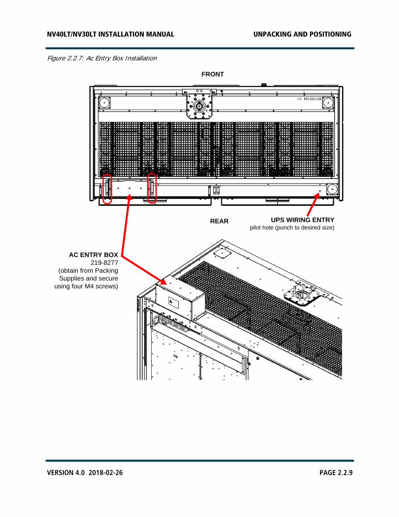
10. Obtain the ac entry box (Nautel Part # 219-8277) and its securing hardware (four M4 screws), which were bagged and packed with the ancillaries. Install the ac entry box, noting proper orientation, on top of the transmitter as shown in Figure 2.2.7 on page 2.2.9.
11. Proceed to Section 2.3, “Installing Options”to configure your transmitter for any options that were purchased.
12. Do not re-install the rear panels at this time.
NV40LT/NV30LT INSTALLATION MANUAL UNPACKING AND POSITIONING
VERSION 4.0 2018-02-26 PAGE 2.2.3
Figure 2.2.1: Front and Rear Access Panels
1/4-TURN LATCHES16 in each rear panel
LOWER, REAR PANELS11 M5 screws eachLOCK OUT AC POWER BEFORE REMOVING!
1/4-TURN LATCHES13 in each front panel
FRONT
REAR
NV40LT/NV30LT INSTALLATION MANUAL UNPACKING AND POSITIONING
PAGE 2.2.4 VERSION 4.0 2018-02-26
Figure 2.2.2: Cabinet Leveler Detail
CABINET LEVELER(located in each corner of transmitter)
NV40LT/NV30LT INSTALLATION MANUAL UNPACKING AND POSITIONING
VERSION 4.0 2018-02-26 PAGE 2.2.5
Figure 2.2.3: Seismic Anchoring Hole Locations
SEISMIC ANCHORINGHOLES4 places (3/4 in holes)
FLOOR VIEW OF CABINET FROM ABOVE
FRONT
NV40LT/NV30LT INSTALLATION MANUAL UNPACKING AND POSITIONING
PAGE 2.2.6 VERSION 4.0 2018-02-26
Figure 2.2.4: RF Power Module Shipping Bolts
M8SHIPPING
BOLTS(1 per
module)
PARTIALREAR VIEW
(FILTERPANELS
REMOVED)
NV40LT/NV30LT INSTALLATION MANUAL UNPACKING AND POSITIONING
VERSION 4.0 2018-02-26 PAGE 2.2.7
Figure 2.2.5: RF Output Connector Assembly Detail - 4-1/16 inch EIA (standard configuration)
TORQUE OUTPUT CONNECTION TO 292 IN-LBS OR 25 FT-LBS
OUTPUTCONNECTORCUP
OUTPUT PLATE
SPACER PLATES
NV40LT/NV30LT INSTALLATION MANUAL UNPACKING AND POSITIONING
PAGE 2.2.8 VERSION 4.0 2018-02-26
Figure 2.2.6: RF Output Connector Assembly Detail - 3-1/8 inch EIA (optional)
TORQUE OUTPUT CONNECTION TO 292 IN-LBS OR 25 FT-LBS
OUTPUTCONNECTORCUP
OUTPUT PLATE
SPACER PLATES
NV40LT/NV30LT INSTALLATION MANUAL UNPACKING AND POSITIONING
VERSION 4.0 2018-02-26 PAGE 2.2.9
Figure 2.2.7: Ac Entry Box Installation
AC ENTRY BOX219-8277
(obtain from PackingSupplies and secure
using four M4 screws)
FRONT
REAR UPS WIRING ENTRYpilot hole (punch to desired size)

NV40LT/NV30LT INSTALLATION MANUAL UNPACKING AND POSITIONING
PAGE 2.2.10 VERSION 4.0 2018-02-26
NV40LT/NV30LT INSTALLATION MANUAL INSTALLING OPTIONS
VERSION 4.0 2018-02-26 PAGE 2.3.1
SECTION 2.3: INSTALLING OPTIONS
The NV40LT/NV30LT transmitter is factory configured and shipped to operate with the customer’s desired ac power source voltage and RF output connector size. There are options available for various other features, including dual exciter, UPS interface, redundant LVPS, and remote interfacing. These options may be installed in one of two ways:
You install and configure options at your site, using kits and instructions provided by Nautel. Each option has a separate kit.
Pre-arrange for Nautel to install and configure options at the factory prior to shipping.
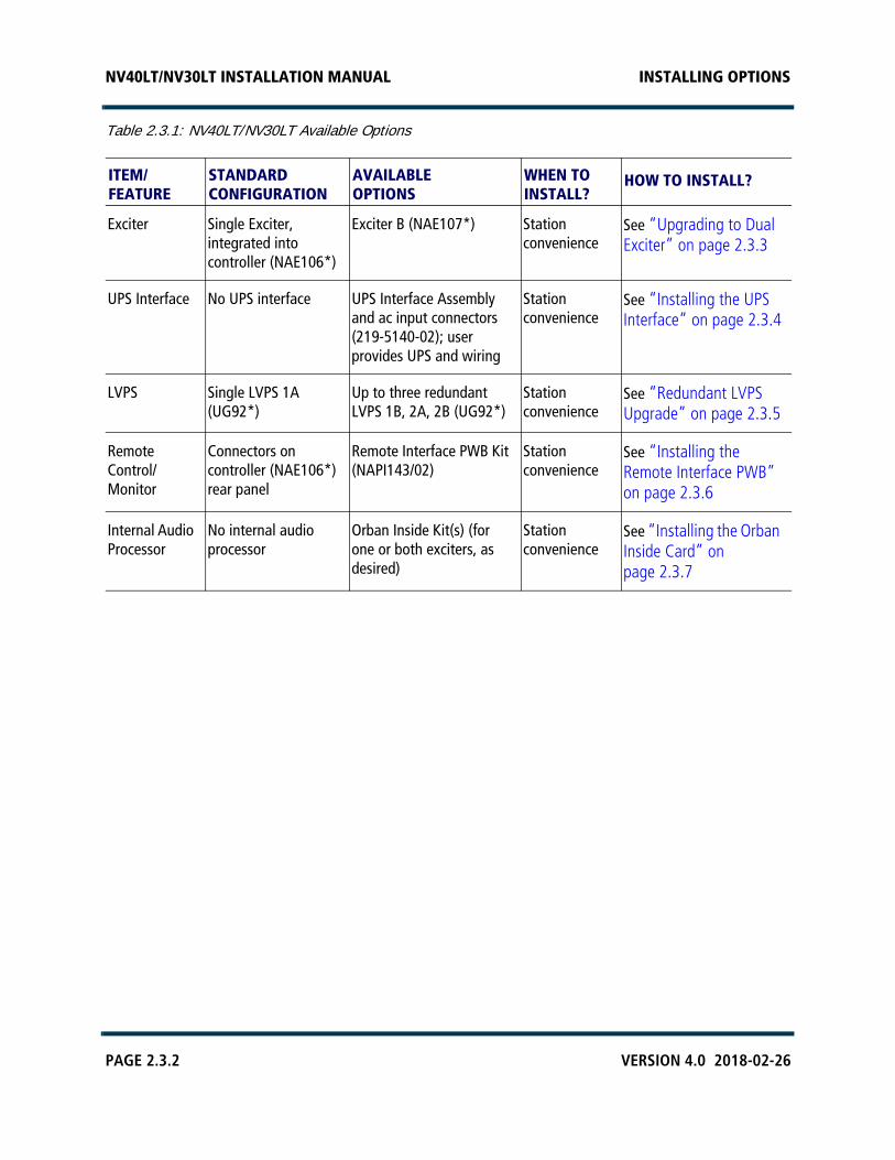
Table 2.3.1 shows the standard (default) configuration of the NV40LT/NV30LT, as well as the available options. Each option references a recommended schedule of installation and the procedure (or associated document) that describes how to install and configure the option. Review the options in Table 2.3.1 to determine which, if any, apply to your installation.
If you did not purchase any options for your NV40LT/NV30LT and intend to operate with the standard (default) configuration, proceed to Section 2.4, “Connecting to Station Reference Ground”.
NOTE: When an option is installed (UPS interface, dual exciter, etc.), the extra parts removed (e.g., blank exciter panel, AC LED cover) from the original configuration are placed in the Ancillary kit.
NV40LT/NV30LT INSTALLATION MANUAL INSTALLING OPTIONS
PAGE 2.3.2 VERSION 4.0 2018-02-26
Table 2.3.1: NV40LT/NV30LT Available Options
ITEM/FEATURE
STANDARD CONFIGURATION
AVAILABLEOPTIONS
WHEN TOINSTALL?
HOW TO INSTALL?
Exciter Single Exciter, integrated into controller (NAE106*)
Exciter B (NAE107*) Station convenience
See “Upgrading to Dual Exciter” on page 2.3.3
UPS Interface No UPS interface UPS Interface Assembly and ac input connectors (219-5140-02); user provides UPS and wiring
Station convenience
See “Installing the UPS Interface” on page 2.3.4
LVPS Single LVPS 1A (UG92*)
Up to three redundant LVPS 1B, 2A, 2B (UG92*)
Station convenience
See “Redundant LVPS Upgrade” on page 2.3.5
Remote Control/Monitor
Connectors on controller (NAE106*) rear panel
Remote Interface PWB Kit (NAPI143/02)
Station convenience
See “Installing the Remote Interface PWB” on page 2.3.6
Internal Audio Processor
No internal audio processor
Orban Inside Kit(s) (for one or both exciters, as desired)
Station convenience
See “Installing the Orban Inside Card” on page 2.3.7
NV40LT/NV30LT INSTALLATION MANUAL INSTALLING OPTIONS
VERSION 4.0 2018-02-26 PAGE 2.3.3
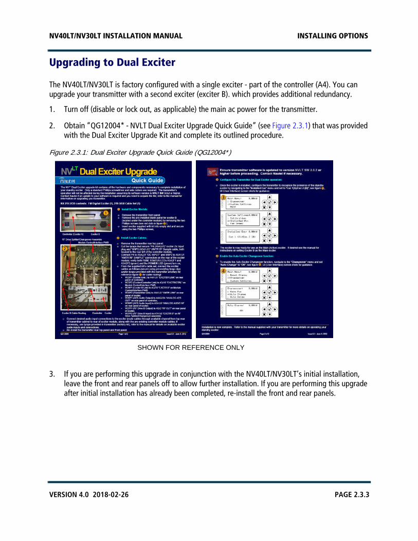
Upgrading to Dual Exciter
The NV40LT/NV30LT is factory configured with a single exciter - part of the controller (A4). You can upgrade your transmitter with a second exciter (exciter B). which provides additional redundancy.
1. Turn off (disable or lock out, as applicable) the main ac power for the transmitter.
2. Obtain “QG12004* - NVLT Dual Exciter Upgrade Quick Guide” (see Figure 2.3.1) that was provided with the Dual Exciter Upgrade Kit and complete its outlined procedure.
Figure 2.3.1: Dual Exciter Upgrade Quick Guide (QG12004*)
3. If you are performing this upgrade in conjunction with the NV40LT/NV30LT’s initial installation, leave the front and rear panels off to allow further installation. If you are performing this upgrade after initial installation has already been completed, re-install the front and rear panels.
SHOWN FOR REFERENCE ONLY
NV40LT/NV30LT INSTALLATION MANUAL INSTALLING OPTIONS
PAGE 2.3.4 VERSION 4.0 2018-02-26
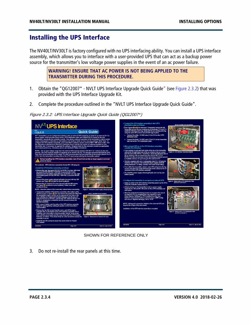
Installing the UPS Interface
The NV40LT/NV30LT is factory configured with no UPS interfacing ability. You can install a UPS interface assembly, which allows you to interface with a user-provided UPS that can act as a backup power source for the transmitter’s low voltage power supplies in the event of an ac power failure.
1. Obtain the “QG12007* - NVLT UPS Interface Upgrade Quick Guide” (see Figure 2.3.2) that was provided with the UPS Interface Upgrade Kit.
2. Complete the procedure outlined in the “NVLT UPS Interface Upgrade Quick Guide”.
Figure 2.3.2: UPS Interface Upgrade Quick Guide (QG12007*)
3. Do not re-install the rear panels at this time.
WARNING! ENSURE THAT AC POWER IS NOT BEING APPLIED TO THE TRANSMITTER DURING THIS PROCEDURE.
SHOWN FOR REFERENCE ONLY
NV40LT/NV30LT INSTALLATION MANUAL INSTALLING OPTIONS
VERSION 4.0 2018-02-26 PAGE 2.3.5
Redundant LVPS Upgrade
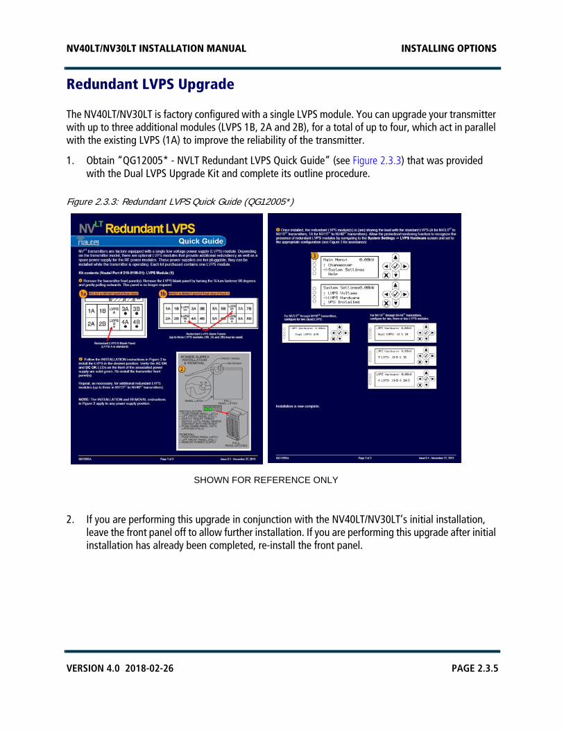
The NV40LT/NV30LT is factory configured with a single LVPS module. You can upgrade your transmitter with up to three additional modules (LVPS 1B, 2A and 2B), for a total of up to four, which act in parallel with the existing LVPS (1A) to improve the reliability of the transmitter.
1. Obtain “QG12005* - NVLT Redundant LVPS Quick Guide” (see Figure 2.3.3) that was provided with the Dual LVPS Upgrade Kit and complete its outline procedure.
Figure 2.3.3: Redundant LVPS Quick Guide (QG12005*)
2. If you are performing this upgrade in conjunction with the NV40LT/NV30LT’s initial installation, leave the front panel off to allow further installation. If you are performing this upgrade after initial installation has already been completed, re-install the front panel.
SHOWN FOR REFERENCE ONLY

NV40LT/NV30LT INSTALLATION MANUAL INSTALLING OPTIONS
PAGE 2.3.6 VERSION 4.0 2018-02-26
Installing the Remote Interface PWB
The NV40LT/NV30LT is factory configured with a controller (A4), which provides remote control and monitoring interfacing on its rear panel. You can install a remote interface PWB (Nautel Part # NAPI143/02) behind the hinged, front UI panel, which provides a more convenient location to make remote wiring connections. The remote interface PWB also contains control switches (push-buttons) and monitoring LEDs, which provide backup control and monitoring for the transmitter in the event of a failure with the front panel UI or remote AUI. It also provides analog output samples of key parameters (forward power, reflected power, PA voltage and total current) for monitoring.
1. Obtain “QG12006* - NVLT Remote Interface PWB Upgrade Quick Guide” (see Figure 2) that was provided with the Remote Interface PWB Upgrade Kit and complete its outlined procedure.
2. If you are performing this upgrade in conjunction with the NV40LT/NV30LT’s initial installation,
leave the front panel off to allow further installation. If you are performing this upgrade after initial installation has already been completed, re-install the front panel.
NOTE: Installing this option changes the location of remote control/monitor and interlock connections. See Section 2.8, “Installing Control/Monitor Wiring” on page 8-1 for more information.
WARNING! ENSURE THAT AC POWER IS NOT BEING APPLIED TO THE TRANSMITTER DURING THIS PROCEDURE.
SHOWN FORREFERENCEONLY

NV40LT/NV30LT INSTALLATION MANUAL INSTALLING OPTIONS
VERSION 4.0 2018-02-26 PAGE 2.3.7
Installing the Orban Inside Card
The NV40LT/NV30LT is factory configured with no internal audio processor. You can install an Orban Inside audio processor card in one or both exciters, as applicable. The controller and optional exciter, if applicable, must be removed from the transmitter to install the Orban Inside card. Once the Orban Inside card is installed, you can configure its audio processor settings using the remote AUI (see the NV40LT/NV30LT Operation & Maintenance Manual for more details).
1. Obtain the “QG12001* - Orban Inside Upgrade Quick Guide”(see Figure 2.3.4) that was provided with the Orban Inside Kit and complete its outlined procedure for each desired exciter. The controller’s integral exciter is exciter A and the optional exciter is exciter B.
Figure 2.3.4: Orban Inside Upgrade Quick Guide (QG12001*)
2. If you are performing this upgrade in conjunction with the NV40LT/NV30LT’s initial installation, leave the front and rear panels off to allow further installation. If you are performing this upgrade after initial installation has already been completed, re-install the front and rear panels.
WARNING! ENSURE THAT AC POWER IS NOT BEING APPLIED TO THE TRANSMITTER DURING THIS PROCEDURE.
SHOWN FORREFERENCE ONLY

NV40LT/NV30LT INSTALLATION MANUAL INSTALLING OPTIONS
PAGE 2.3.8 VERSION 4.0 2018-02-26
NV40LT/NV30LT INSTALLATION MANUAL CONNECTING TO STATION REFERENCE GROUND
VERSION 4.0 2018-02-26 PAGE 2.4.1
SECTION 2.4: CONNECTING TO STATION REFERENCE GROUND
To connect to the station reference ground, perform the following steps:
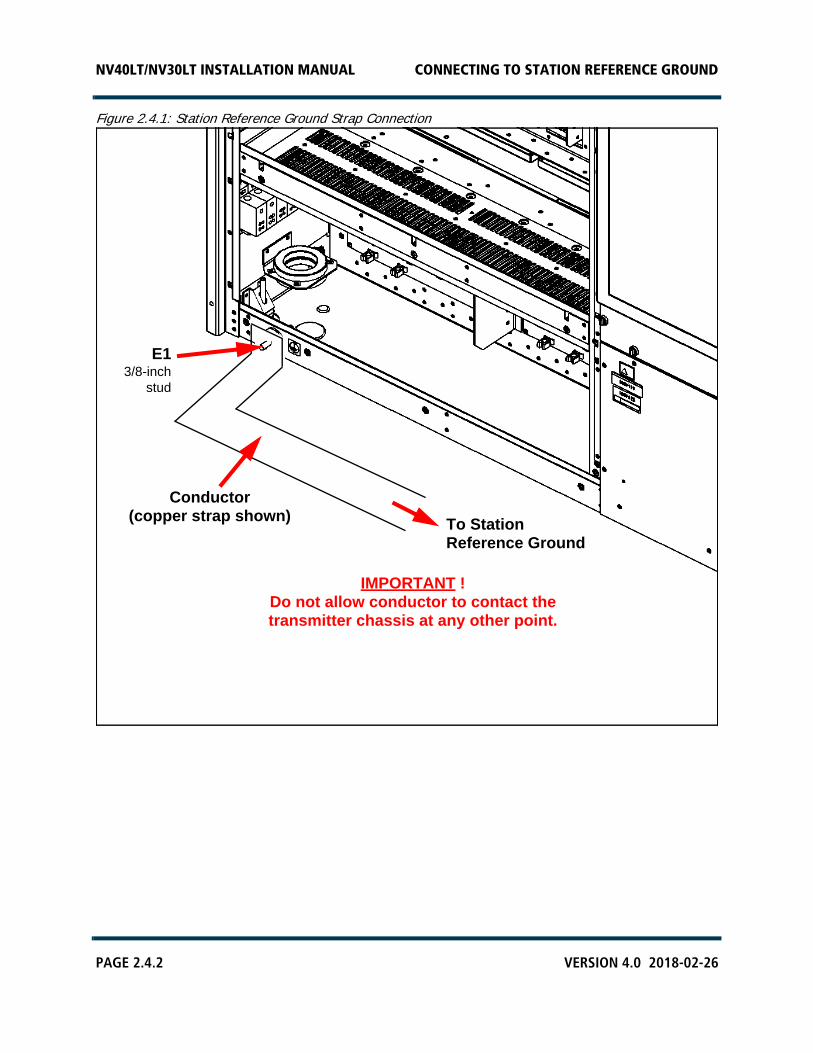
1. Locate the safety ground stud assembly (E1) for the transmitter at the bottom rear of the cabinet (see Figure 2.4.1 on page 4-2).
2. Attach a continuous, low impedance conductor (minimum four-inch copper strap) between the station reference ground and the stud assembly (E1) on the cabinet. Secure the conductor to E1 using the stud’s 3/8-inch nut and a suitable wrench. Ensure the reference ground conductor is at least 3 mm (1/8 in) from the cabinet’s exterior.
3. For information about grounding the lightning protection, see the NV40LT/NV30LT Pre-Installation Manual. For detailed information about lightning protection, see the Nautel Site Preparation Manual, available from your Nautel sales agent, or online from the Nautel website.
4. Firmly tighten all hardware. Do not re-install the rear panels at this time.
CAUTION! IT IS IMPORTANT THAT THE CONDUCTOR ATTACHED TO E1 DOES NOT CONTACT THE TRANSMITTER CHASSIS AT ANY OTHER POINT.
NV40LT/NV30LT INSTALLATION MANUAL CONNECTING TO STATION REFERENCE GROUND
PAGE 2.4.2 VERSION 4.0 2018-02-26
Figure 2.4.1: Station Reference Ground Strap Connection
E13/8-inch
stud
IMPORTANT !Do not allow conductor to contact thetransmitter chassis at any other point.
To StationReference Ground
Conductor(copper strap shown)
NV40LT/NV30LT INSTALLATION MANUAL CONNECTING AC POWER
VERSION 4.0 2018-02-26 PAGE 2.5.1
SECTION 2.5: CONNECTING AC POWERConnect ac power to the transmitter as follows:
NOTE: The transmitter’s internal wiring is factory configured to operate from the customer’s desired ac power source. Ensure that the ac configuration label on the transmitter agrees with the main ac power source voltage that you are connecting.
1. Switch off the main ac power at the service entrance. As viewed from the rear, remove the left-hand side rear filter panel (1/4-turn fasteners) from the transmitter.
2. Select the appropriate wire size for your main ac power cables. See the NV40LT/NV30LT Pre-Installation Manual for assistance. Ensure the ground wire is insulated, so it does not contact the transmitter cabinet at any location other than the safety ground stud.
NOTE: Some types of cable (e.g., TEC cable) have an exposed ground wire. In such cases, Nautel recommends that you sleeve (insulate) the ground wire.
3. Route the main ac power cables in a suitable conduit, from the ac disconnect switch to the top of the transmitter.
4. Punch the appropriate size hole in the ac entry box as follows (see Figure 2.5.1 on page 2.5.5):
Remove the top cover from the ac entry box. It is secured using four M4 screws and has three pre-cut, 1/4-inch diameter holes.
Use a chassis punch tool (e.g., Greenlee, etc.) to punch the desired size hole(s) in the top cover. Make sure the ac input cables will pass safely through the hole(s).
Re-install the top cover on the ac entry box using four M4 screws.
5. Verify that the station reference ground is connected to the ground stud at the back of the cabinet. See Section 2.4, “Connecting to Station Reference Ground” on page 2.4.1, if necessary.
6. Route the ac power cables through the hole(s) punched in the top of the ac input entry box to the ac input terminal block (TB1) (see Figure 2.5.1 on page 2.5.5).
NOTE: The NV40LT/NV30LT contains pre-installed ferrite toroids for internal ac wiring. For this reason, additional ferrite toroids should not be required for the ac input wiring. The ancillary kit contains ferrite toroids (Nautel Part # LP32) for use with the ac input wiring, if desired.
7. Temporarily remove the rear cover from the ac input entry box (four M4 screws), noting the cover is secured to the box with a bonding (ground) wire, which should not be disconnected.
WARNING! ENSURE THAT WIRING SIZES ARE APPROPRIATE. AC WIRING MUST BE INSTALLED BY A QUALIFIED, LOCALLY-CERTIFIED ELECTRICIAN.
NV40LT/NV30LT INSTALLATION MANUAL CONNECTING AC POWER
PAGE 2.5.2 VERSION 4.0 2018-02-26
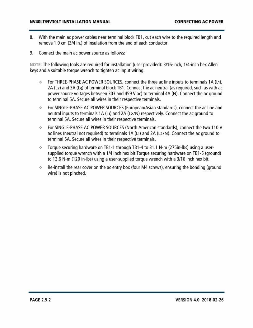
8. With the main ac power cables near terminal block TB1, cut each wire to the required length and remove 1.9 cm (3/4 in.) of insulation from the end of each conductor.
9. Connect the main ac power source as follows:
NOTE: The following tools are required for installation (user provided): 3/16-inch, 1/4-inch hex Allen keys and a suitable torque wrench to tighten ac input wiring.
For THREE-PHASE AC POWER SOURCES, connect the three ac line inputs to terminals 1A (L1), 2A (L2) and 3A (L3) of terminal block TB1. Connect the ac neutral (as required, such as with ac power source voltages between 303 and 459 V ac) to terminal 4A (N). Connect the ac ground to terminal 5A. Secure all wires in their respective terminals.
For SINGLE-PHASE AC POWER SOURCES (European/Asian standards), connect the ac line and neutral inputs to terminals 1A (L1) and 2A (L2/N) respectively. Connect the ac ground to terminal 5A. Secure all wires in their respective terminals.
For SINGLE-PHASE AC POWER SOURCES (North American standards), connect the two 110 V ac lines (neutral not required) to terminals 1A (L1) and 2A (L2/N). Connect the ac ground to terminal 5A. Secure all wires in their respective terminals.
Torque securing hardware on TB1-1 through TB1-4 to 31.1 N-m (275in-lbs) using a user-supplied torque wrench with a 1/4 inch hex bit.Torque securing hardware on TB1-5 (ground) to 13.6 N-m (120 in-lbs) using a user-supplied torque wrench with a 3/16 inch hex bit.
Re-install the rear cover on the ac entry box (four M4 screws), ensuring the bonding (ground wire) is not pinched.

NV40LT/NV30LT INSTALLATION MANUAL CONNECTING AC POWER
VERSION 4.0 2018-02-26 PAGE 2.5.3
10. If the UPS interface option has been installed, remove the bottom UPS Entry panel (eleven M5 screws) and route the ac cable from the user-provided UPS, through the desired top or bottom entry point (see Figure 2.5.1 on page 2.5.5), to the UPS interface assembly at the bottom of the transmitter. Install the Nautel provided mating connector and install the ac cable on the UPS interface assembly. Refer to “Configuring an External UPS” on page 2.9.7“Configuring an External UPS” on page 2.9.11 to configure the transmitter to recognize the UPS. See the NV40LT/NV30LT Pre-installation Manual for more information.
11. If previously removed, re-install the bottom rear panel removed in Step 14, using the retained M5 screws.
12. Do not install the rear filter panel at this time.
NV40LT/NV30LT INSTALLATION MANUAL CONNECTING AC POWER
PAGE 2.5.4 VERSION 4.0 2018-02-26
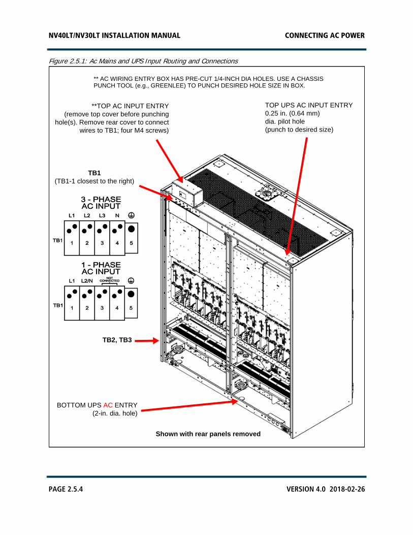
Figure 2.5.1: Ac Mains and UPS Input Routing and Connections
**TOP AC INPUT ENTRY(remove top cover before punching
hole(s). Remove rear cover to connectwires to TB1; four M4 screws)
** AC WIRING ENTRY BOX HAS PRE-CUT 1/4-INCH DIA HOLES. USE A CHASSISPUNCH TOOL (e.g., GREENLEE) TO PUNCH DESIRED HOLE SIZE IN BOX.
Shown with rear panels removed
TOP UPS AC INPUT ENTRY0.25 in. (0.64 mm)dia. pilot hole(punch to desired size)
TB1(TB1-1 closest to the right)
BOTTOM UPS AC ENTRY(2-in. dia. hole)
TB2, TB3
NV40LT/NV30LT INSTALLATION MANUAL CONNECTING AC POWER
VERSION 4.0 2018-02-26 PAGE 2.5.5
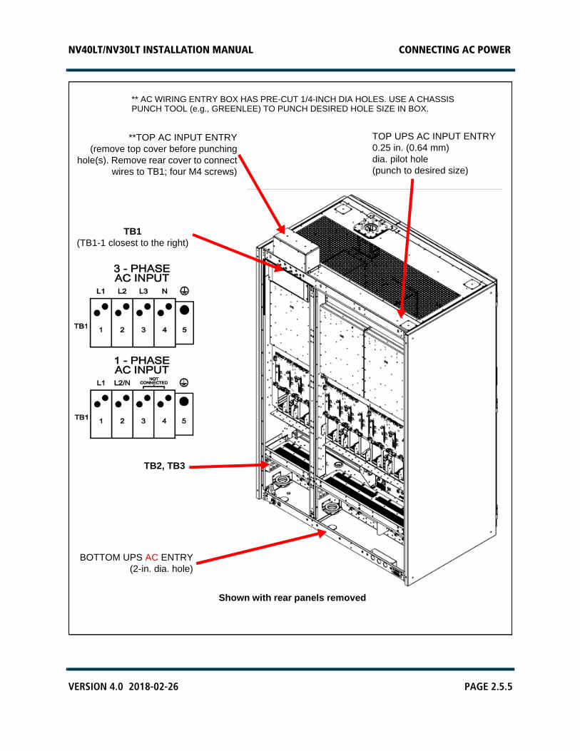
**TOP AC INPUT ENTRY(remove top cover before punching
hole(s). Remove rear cover to connectwires to TB1; four M4 screws)
** AC WIRING ENTRY BOX HAS PRE-CUT 1/4-INCH DIA HOLES. USE A CHASSISPUNCH TOOL (e.g., GREENLEE) TO PUNCH DESIRED HOLE SIZE IN BOX.
Shown with rear panels removed
TOP UPS AC INPUT ENTRY0.25 in. (0.64 mm)dia. pilot hole(punch to desired size)
TB1(TB1-1 closest to the right)
BOTTOM UPS AC ENTRY(2-in. dia. hole)
TB2, TB3

NV40LT/NV30LT INSTALLATION MANUAL CONNECTING AC POWER
PAGE 2.5.6 VERSION 4.0 2018-02-26

NV40LT/NV30LT INSTALLATION MANUAL INSTALLING THE RF FEED CABLE
VERSION 4.0 2018-02-26 PAGE 2.6.1
SECTION 2.6: INSTALLING THE RF FEED CABLE
Prepare and install an RF feed coaxial cable as follows:
NOTE: Nautel recommends that you perform the commissioning procedure in Section 2.9, “Commissioning”Section 2.9, “Commissioning”, which connects the transmitter to a dummy load, before connecting the transmitter to its antenna system.
1. Make sure the transmitter is configured for the correct RF output connector. It is factory configured for the customer’s desired RF output connector [4-1/16 inch EIA (standard) or 3-1/8 inch EIA (optional)][3-1/8 inch EIA (standard) or 4-1/16 inch EIA (optional)].
2. Connect the transmitter's RF output to a dummy load, if available, during the commissioning procedure's initial turn on.
3. Verify the RF feed cable is in place and is cut to the required length. Do not install the EIA flange connector at this point.
4. Get two ferrite toroids from the ancillary kit that are sufficient to accommodate the associated feed cable or hardline. For 4-1/16 inch or 3-1/8 inch feed cable, use Nautel Part # LP32 (4.165 inch inner diameter). Install two ferrite toroids on the transmitter end of the feed cable or hardline. See Figure 2.6.1 on page 2.6.2.
5. Install the user-provided appropriate size EIA flange connector on the feed cable.
6. If the RF feed cable's EIA flange connector does not have a male connector for the center conductor, obtain an EIA bullet for the EIA flange connector. Nautel does not provide an EIA bullet.
WARNING! ENSURE THAT AC POWER IS NOT BEING APPLIED TO THE TRANSMITTER DURING THIS PROCEDURE.
NOTE! Nautel does not typically supply bullets as there is no guarantee that they will be compatible with all potential hardline used at the customer's site. It is recommended that the customer supply this part and ensure a snug fit exists between the transmitter RF output cup and EIA flange connector in Step 6 and Step 8. Use sufficient insertion force to ensure low contact resistance. Failure to observe these recommendations may result in damage to the transmitter or feedline.
NV40LT/NV30LT INSTALLATION MANUAL INSTALLING THE RF FEED CABLE
PAGE 2.6.2 VERSION 4.0 2018-02-26
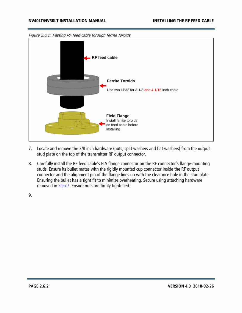
Figure 2.6.1: Passing RF feed cable through ferrite toroids
7. Locate and remove the 3/8 inch hardware (nuts, split washers and flat washers) from the output stud plate on the top of the transmitter RF output connector.
8. Carefully install the RF feed cable's EIA flange connector on the RF connector’s flange-mounting studs. Ensure its bullet mates with the rigidly mounted cup connector inside the RF output connector and the alignment pin of the flange lines up with the clearance hole in the stud plate. Ensuring the bullet has a tight fit to minimize overheating. Secure using attaching hardware removed in Step 7. Ensure nuts are firmly tightened.
9.
RF feed cable
Ferrite Toroids
Use two LP32 for 3-1/8 and 4-1/16 inch cable
Field FlangeInstall ferrite toroids on feed cable before installing
NV40LT/NV30LT INSTALLATION MANUAL INSTALLING PROGRAM INPUTS
VERSION 4.0 2018-02-26 PAGE 2.7.1
SECTION 2.7: INSTALLING PROGRAM INPUTS
This section describes how to route program input wiring to the NV40LT/NV30LT’s exciter(s).
Planning Complete?
1. Make sure you have read and fully understood the program input options described in the NV40LT/NV30LT Pre-installation Manual before proceeding.
2. Make sure the program input wires are long enough to allow routing through the top of the transmitter cabinet and down to the rear panel of the controller and exciter (if applicable).
3. If you ordered the optional Exciter Upgrade kit, make sure it is installed (see “Upgrading to Dual Exciter” on page 2.3.5). The transmitter is factory configured with a single exciter - within the controller (A4).
4. If you ordered the optional Orban Inside Audio Processor kit for one or both exciters, as applicable, make sure it is installed (see “Installing the Orban Inside Card” on page 2.3.8). The transmitter’s exciters are factory configured with no Orban Inside audio processor card.
Routing Cables
Route the desired analog and digital program input cables to the back of the NV40LT/NV30LT’s controller and optional exciter.
1. Route all program input cables from their audio sources to the top of the transmitter. If you are using dual exciters, you will need two sets of program inputs - one for each exciter.
2. Get two ferrite toroids (Nautel Part # LXP38, 19 mm inner diameter) from the ancillary kit for each exciter installed. The controller’s integral exciter is exciter A. The optional exciter, if installed, is exciter B.
3. Pass all program input cables through the ferrite toroids obtained in Step 2. If practical, wires should pass through a minimum of two times (two turns) (see Figure 2.7.1 on page 2.7.2). An entrance is provided at the top of the transmitter to accept program input wiring. Position the ferrite toroids just outside, or just inside, the program input entry hole.
4. Punch the appropriate size hole in the program input entry plate (see Figure 2.7.2 on page 2.7.3):
Remove the program input entry plate from the top of the transmitter. It is secured using four M4 screws and has a pre-cut, centered 1/4-inch diameter hole.
NV40LT/NV30LT INSTALLATION MANUAL INSTALLING PROGRAM INPUTS
PAGE 2.7.2 VERSION 4.0 2018-02-26
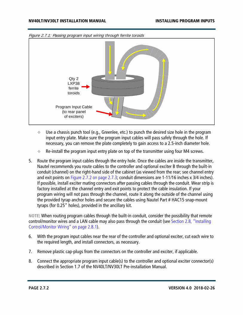
Figure 2.7.1: Passing program input wiring through ferrite toroids
Use a chassis punch tool (e.g., Greenlee, etc.) to punch the desired size hole in the program input entry plate. Make sure the program input cables will pass safely through the hole. If necessary, you can remove the plate completely to gain access to a 2.5-inch diameter hole.
Re-install the program input entry plate on top of the transmitter using four M4 screws.
5. Route the program input cables through the entry hole. Once the cables are inside the transmitter, Nautel recommends you route cables to the controller and optional exciter B through the built-in conduit (channel) on the right-hand side of the cabinet (as viewed from the rear; see channel entry and exit points on Figure 2.7.2 on page 2.7.3; conduit dimensions are 1-11/16 inches x 3/4 inches). If possible, install exciter mating connectors after passing cables through the conduit. Wear strip is factory installed at the channel entry and exit points to protect the cable insulation. If your program wiring will not pass through the channel, route it along the outside of the channel using the provided tyrap anchor holes and secure the cables using Nautel Part # HAC15 snap-mount tyraps (for 0.25” holes), provided in the ancillary kit.
NOTE: When routing program cables through the built-in conduit, consider the possibility that remote control/monitor wires and a LAN cable may also pass through the conduit (see Section 2.8, “Installing Control/Monitor Wiring” on page 2.8.1).
6. With the program input cables near the rear of the controller and optional exciter, cut each wire to the required length, and install connectors, as necessary.
7. Remove plastic cap-plugs from the connectors on the controller and exciter, if applicable.
8. Connect the appropriate program input cable(s) to the controller and optional exciter connector(s) described in Section 1.7 of the NV40LT/NV30LT Pre-installation Manual.
Program Input Cable(to rear panelof exciters)
Qty 2 LXP38 ferrite toroids
NV40LT/NV30LT INSTALLATION MANUAL INSTALLING PROGRAM INPUTS
VERSION 4.0 2018-02-26 PAGE 2.7.3
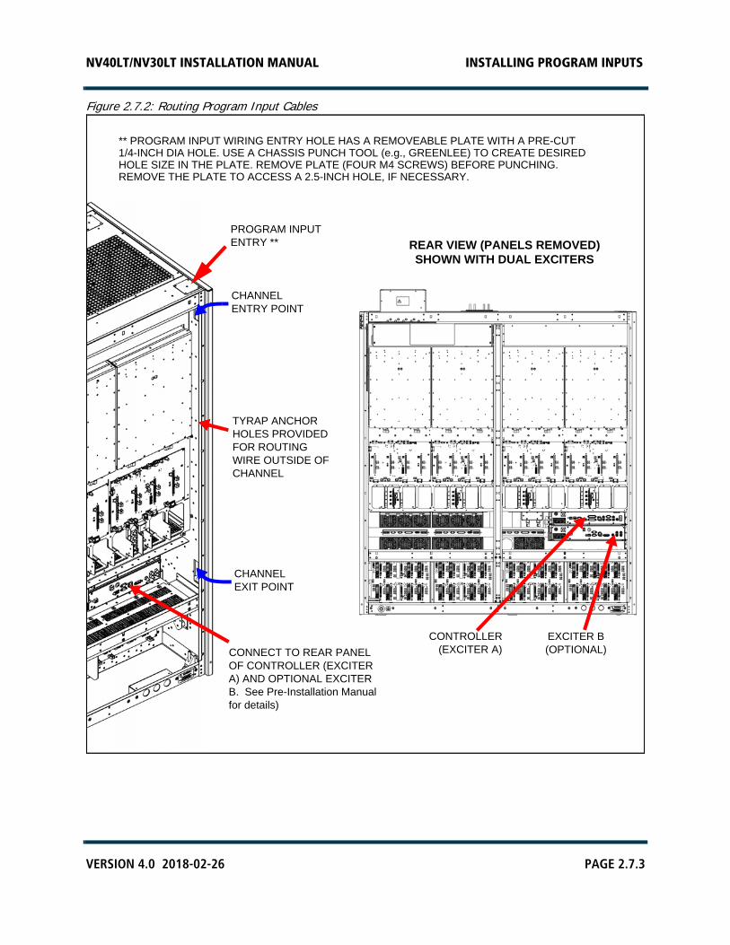
Figure 2.7.2: Routing Program Input Cables
** PROGRAM INPUT WIRING ENTRY HOLE HAS A REMOVEABLE PLATE WITH A PRE-CUT 1/4-INCH DIA HOLE. USE A CHASSIS PUNCH TOOL (e.g., GREENLEE) TO CREATE DESIREDHOLE SIZE IN THE PLATE. REMOVE PLATE (FOUR M4 SCREWS) BEFORE PUNCHING.REMOVE THE PLATE TO ACCESS A 2.5-INCH HOLE, IF NECESSARY.
PROGRAM INPUTENTRY **
CHANNELENTRY POINT
CHANNELEXIT POINT
TYRAP ANCHOR HOLES PROVIDED FOR ROUTING WIRE OUTSIDE OF CHANNEL
CONNECT TO REAR PANEL OF CONTROLLER (EXCITER A) AND OPTIONAL EXCITER B. See Pre-Installation Manual for details)
CONTROLLER(EXCITER A)
EXCITER B(OPTIONAL)
REAR VIEW (PANELS REMOVED)SHOWN WITH DUAL EXCITERS

NV40LT/NV30LT INSTALLATION MANUAL INSTALLING PROGRAM INPUTS
PAGE 2.7.4 VERSION 4.0 2018-02-26
NV40LT/NV30LT INSTALLATION MANUAL INSTALLING CONTROL/MONITOR WIRING
VERSION 4.0 2018-02-26 PAGE 2.8.1
SECTION 2.8: INSTALLING CONTROL/MONITOR WIRING
This section describes how to route wiring associated with the remote control and monitoring of the NV40LT/NV30LT transmitter.
Planning Complete?
1. Make sure you have read and fully understood the control and monitoring options described in the NV40LT/NV30LT Pre-installation Manual before proceeding.
2. Make sure the control/monitor wires are long enough to allow routing through the top of the transmitter cabinet and down to the rear panel of the controller (A4) or optional remote interface PWB (A16) at the top, front of the transmitter.
3. If you ordered the optional Remote Interface PWB Kit, make sure it is installed (see “Installing the Remote Interface PWB” on page 2.3.6). The transmitter is factory configured without the remote interface PWB.
NOTE: The transmitter’s factory configuration allows for remote interfacing with connectors on the rear of the controller (A4). If you installed the optional remote interface PWB (A16) (see Figure 2.8.2 on page 2.8.4), you can interface with connectors on the remote interface PWB, which is located behind the front, hinged UI panel.
Routing Cables
1. Route all remote control/monitor cables to the top of the transmitter.
2. Get two ferrite toroids (Nautel Part # LXP38, 19 mm inner diameter) from the ancillary kit.
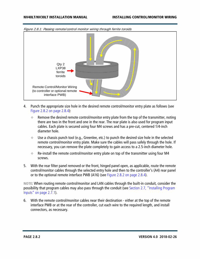
3. Pass all remote control and monitor cables through the ferrite toroids obtained in Step 2. If practical, wires should pass through a minimum of two times (two turns) (see Figure 2.8.1).
If remote control/monitor wiring is being routed to the rear of the controller (A4), use the entrance hole at the top, rear of the transmitter (same hole as program input cable entry).
If remote control/monitor wiring is being routed to the optional remote interface PWB (A16), use the entrance hole at the top, front, right-hand side of the transmitter.
Position the ferrite toroids near the transmitter cabinet - on top or inside.
NV40LT/NV30LT INSTALLATION MANUAL INSTALLING CONTROL/MONITOR WIRING
PAGE 2.8.2 VERSION 4.0 2018-02-26
Figure 2.8.1: Passing remote/control monitor wiring through ferrite toroids
4. Punch the appropriate size hole in the desired remote control/monitor entry plate as follows (see Figure 2.8.2 on page 2.8.4):
Remove the desired remote control/monitor entry plate from the top of the transmitter, noting there are two in the front and one in the rear. The rear plate is also used for program input cables. Each plate is secured using four M4 screws and has a pre-cut, centered 1/4-inch diameter hole.
Use a chassis punch tool (e.g., Greenlee, etc.) to punch the desired size hole in the selected remote control/monitor entry plate. Make sure the cables will pass safely through the hole. If necessary, you can remove the plate completely to gain access to a 2.5-inch diameter hole.
Re-install the remote control/monitor entry plate on top of the transmitter using four M4 screws.
5. With the rear filter panel removed or the front, hinged panel open, as applicable, route the remote control/monitor cables through the selected entry hole and then to the controller’s (A4) rear panel or to the optional remote interface PWB (A16) (see Figure 2.8.2 on page 2.8.4).
NOTE: When routing remote control/monitor and LAN cables through the built-in conduit, consider the possibility that program cables may also pass through the conduit (see Section 2.7, “Installing Program Inputs” on page 2.7.1).
6. With the remote control/monitor cables near their destination - either at the top of the remote interface PWB or at the rear of the controller, cut each wire to the required length, and install connectors, as necessary.
Remote Control/Monitor Wiring (to controller or optional remote
interface PWB)
Qty 2 LXP38 ferrite toroids
NV40LT/NV30LT INSTALLATION MANUAL INSTALLING CONTROL/MONITOR WIRING
VERSION 4.0 2018-02-26 PAGE 2.8.3
7. Connect the appropriate control/monitor cable(s) to the connector(s) described in Section 1.8 of the NV40LT/NV30LT Pre-installation Manual.
If your transmitter has the optional remote interface PWB, route the control/monitor cables to the top edge of the remote interface PWB. Strip a small amount of wire from the end of each wire and connect the control/monitor cables to the appropriate terminals of the CUSTOMER ALARM/STATUS (TB2) and CUSTOMER CONTROL (TB3) terminal blocks.
If your transmitter has the standard configuration (i.e., no remote interface PWB), route the control/monitor cables to the rear of the controller (A4). The transmitter’s ancillary kit contains male (Nautel Part # JS31) and female (Nautel Part # JS28) 25-pin D-sub connectors and connector shells (Nautel Part # JS35) to facilitate connections to the REMOTE I/O-A (A1J2A) and REMOTE I/O-B (A1J2B) 25-pin D-sub connectors.
8. For the transmitter’s external interlock control, route a shielded cable to one of the following locations:
If your transmitter has the optional remote interface PWB, connect the shielded cable to TB1, between INTLK terminals 1 and 2 (see Figure 2.8.2 on page 2.8.4) or between terminals 19 and 20 on the CUSTOMER CONTROL terminal block (TB3). Use one option only; do not use both.
If your transmitter has the standard configuration (i.e., no remote interface PWB), connect the shielded cable to pins 19 and 20 on the REMOTE I/O-A 25-pin male D-sub connector (A1J2A) on the rear panel of the controller (A4).
9. For web based control of the transmitter, route an Ethernet (shielded Cat5) cable to one of the following locations:
If your transmitter has the optional remote interface PWB, route the Ethernet cable to the right-hand edge of the remote interface PWB. Connect the Ethernet cable to the LAN connector (J1) (see Figure 2.8.2 on page 2.8.4).
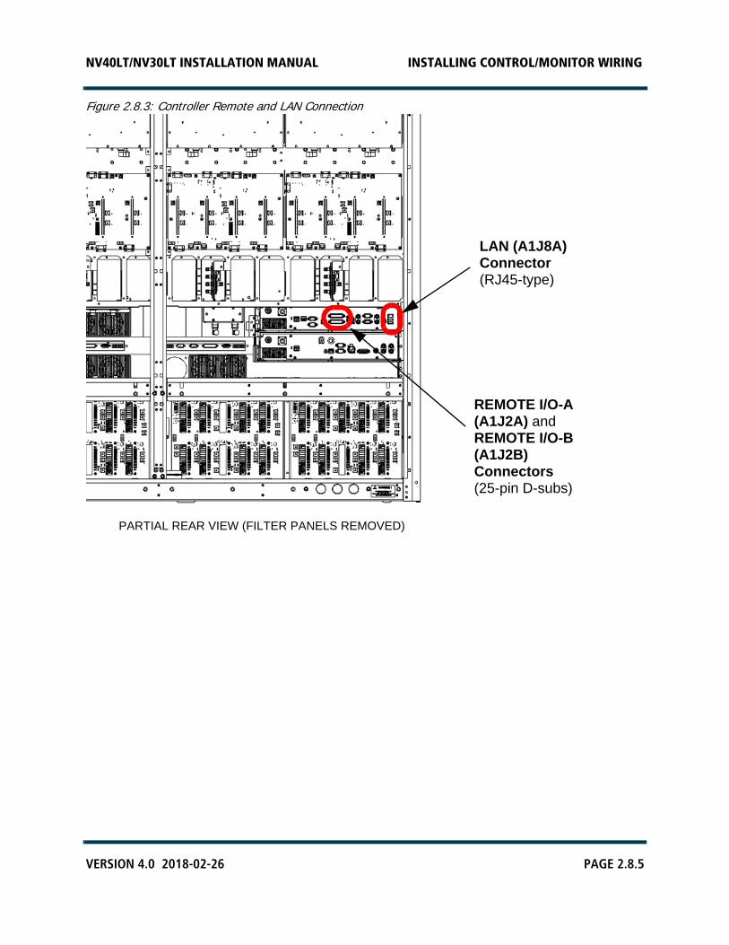
If your transmitter has the standard configuration (i.e., no remote interface PWB), route the Ethernet cable to the rear panel of the controller (A4), accessible from the rear of the transmitter. Connect the Ethernet cable to the LAN (A1J8A) connector (see Figure 2.8.3 on page 2.8.5).
10. Re-install the rear filter panels, removed in Section 2.2, using their 16 1/4-turn latches (see Figure 2.2.1 on page 2.2.3).
NV40LT/NV30LT INSTALLATION MANUAL INSTALLING CONTROL/MONITOR WIRING
PAGE 2.8.4 VERSION 4.0 2018-02-26
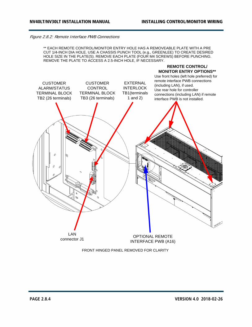
Figure 2.8.2: Remote Interface PWB Connections
** EACH REMOTE CONTROL/MONITOR ENTRY HOLE HAS A REMOVEABLE PLATE WITH A PRE CUT 1/4-INCH DIA HOLE. USE A CHASSIS PUNCH TOOL (e.g., GREENLEE) TO CREATE DESIREDHOLE SIZE IN THE PLATE(S). REMOVE EACH PLATE (FOUR M4 SCREWS) BEFORE PUNCHING.REMOVE THE PLATE TO ACCESS A 2.5-INCH HOLE, IF NECESSARY.
OPTIONAL REMOTEINTERFACE PWB (A16)
CUSTOMERALARM/STATUS
TERMINAL BLOCK TB2 (26 terminals)
CUSTOMERCONTROL
TERMINAL BLOCK TB3 (26 terminals)
EXTERNALINTERLOCKTB1(terminals
1 and 2)
FRONT HINGED PANEL REMOVED FOR CLARITY
LANconnector J1
REMOTE CONTROL/MONITOR ENTRY OPTIONS**
Use front holes (left hole preferred) for remote interface PWB connections(including LAN), if used.Use rear hole for controllerconnections (including LAN) if remoteinterface PWB is not installed.
NV40LT/NV30LT INSTALLATION MANUAL INSTALLING CONTROL/MONITOR WIRING
VERSION 4.0 2018-02-26 PAGE 2.8.5
Figure 2.8.3: Controller Remote and LAN Connection
LAN (A1J8A)Connector(RJ45-type)
PARTIAL REAR VIEW (FILTER PANELS REMOVED)
REMOTE I/O-A (A1J2A) and REMOTE I/O-B (A1J2B)Connectors(25-pin D-subs)

NV40LT/NV30LT INSTALLATION MANUAL INSTALLING CONTROL/MONITOR WIRING
PAGE 2.8.6 VERSION 4.0 2018-02-26

NV40LT/NV30LT INSTALLATION MANUAL COMMISSIONING
VERSION 4.0 2018-02-26 PAGE 2.9.1
SECTION 2.9: COMMISSIONING
The transmitter contains solid-state devices that may be damaged if subjected to excessive heat or high-voltage transients. Ensure that circuits are not overdriven or disconnected from their loads while turned on.
The transmitter was precisely calibrated and tested during manufacturing. Do not change any adjustments other than those specified.
This section contains the following procedures:
• Pre-Commissioning Tasks - see page 2.9.2
• Commissioning - see page 2.9.3
– Turning on the Transmitter - see page 2.9.3– Going On-Air - see page 2.9.8
• Network Setup - see page 2.9.9
• Configuring an External UPS - see page 2.9.11
WARNING! Before applying ac power and turning on the transmitter, you must customize some circuits to the station's power source and operating requirements. Do not perform this pre-commissioning unless you are a station engineer or a competent electronics technician.
NV40LT/NV30LT INSTALLATION MANUAL COMMISSIONING
PAGE 2.9.2 VERSION 4.0 2018-02-26
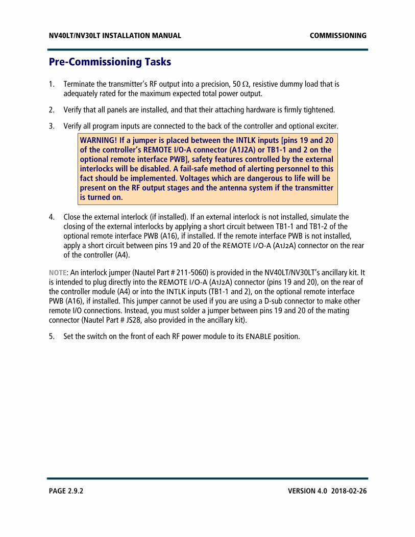
Pre-Commissioning Tasks
1. Terminate the transmitter's RF output into a precision, 50 , resistive dummy load that is adequately rated for the maximum expected total power output.
2. Verify that all panels are installed, and that their attaching hardware is firmly tightened.
3. Verify all program inputs are connected to the back of the controller and optional exciter.
4. Close the external interlock (if installed). If an external interlock is not installed, simulate the closing of the external interlocks by applying a short circuit between TB1-1 and TB1-2 of the optional remote interface PWB (A16), if installed. If the remote interface PWB is not installed, apply a short circuit between pins 19 and 20 of the REMOTE I/O-A (A1J2A) connector on the rear of the controller (A4).
NOTE: An interlock jumper (Nautel Part # 211-5060) is provided in the NV40LT/NV30LT’s ancillary kit. It is intended to plug directly into the REMOTE I/O-A (A1J2A) connector (pins 19 and 20), on the rear of the controller module (A4) or into the INTLK inputs (TB1-1 and 2), on the optional remote interface PWB (A16), if installed. This jumper cannot be used if you are using a D-sub connector to make other remote I/O connections. Instead, you must solder a jumper between pins 19 and 20 of the mating connector (Nautel Part # JS28, also provided in the ancillary kit).
5. Set the switch on the front of each RF power module to its ENABLE position.
WARNING! If a jumper is placed between the INTLK inputs [pins 19 and 20 of the controller’s REMOTE I/O-A connector (A1J2A) or TB1-1 and 2 on the optional remote interface PWB], safety features controlled by the external interlocks will be disabled. A fail-safe method of alerting personnel to this fact should be implemented. Voltages which are dangerous to life will be present on the RF output stages and the antenna system if the transmitter is turned on.
NV40LT/NV30LT INSTALLATION MANUAL COMMISSIONING
VERSION 4.0 2018-02-26 PAGE 2.9.3
Commissioning
NOTE: The following procedures require the use of the transmitter’s front panel UI. If you require assistance to navigate the front panel UI, refer to the NV40LT/NV30LT Operations & Maintenance Manual for more information.
Turning on the Transmitter
1. Switch on the ac power at the service entrance to turn on the transmitter. Confirm the ac voltage, noting the CSA label on the back of the transmitter.
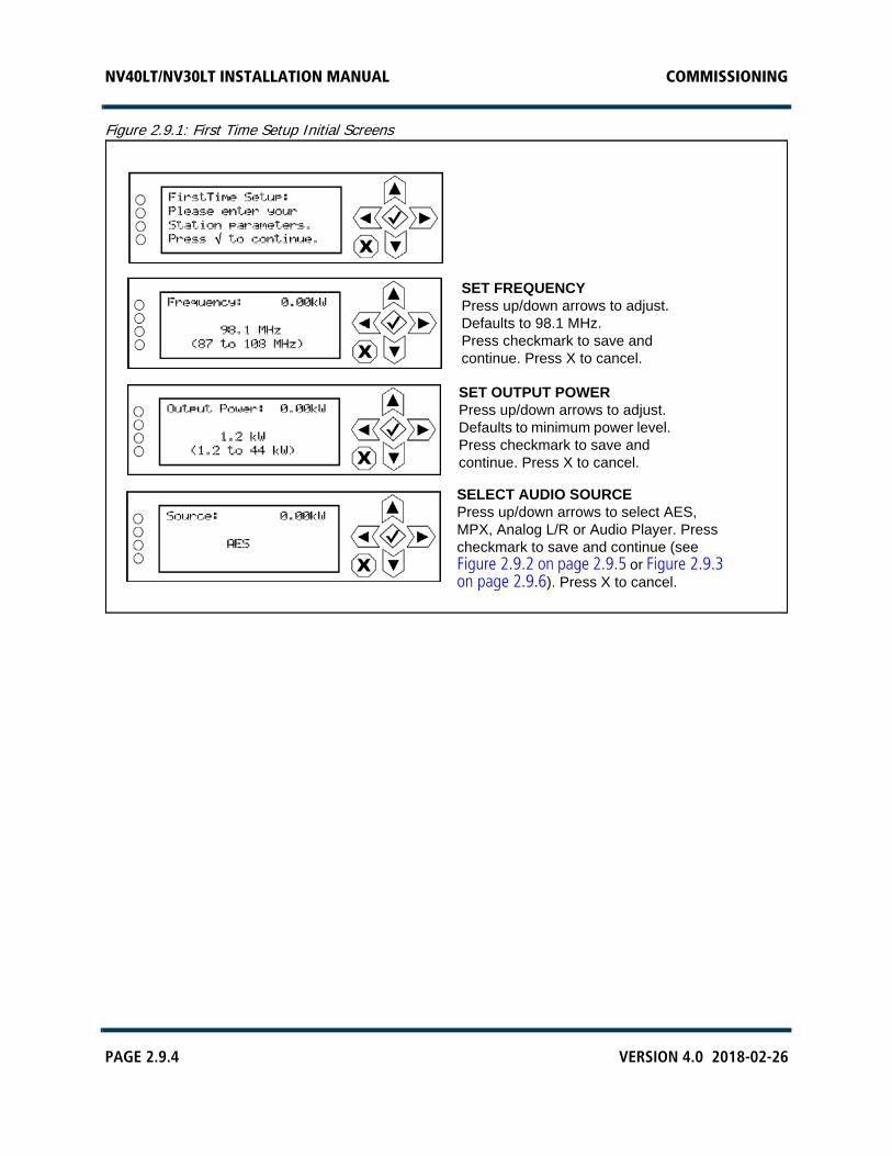
2. Follow the instructions on the front panel display (see Figure 2.9.1 on page 2.9.4) to perform the first-time setup of the NV40LT/NV30LT, including selecting the frequency, output power and audio source.
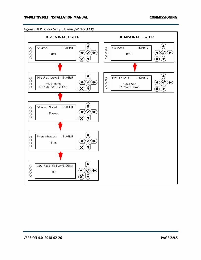
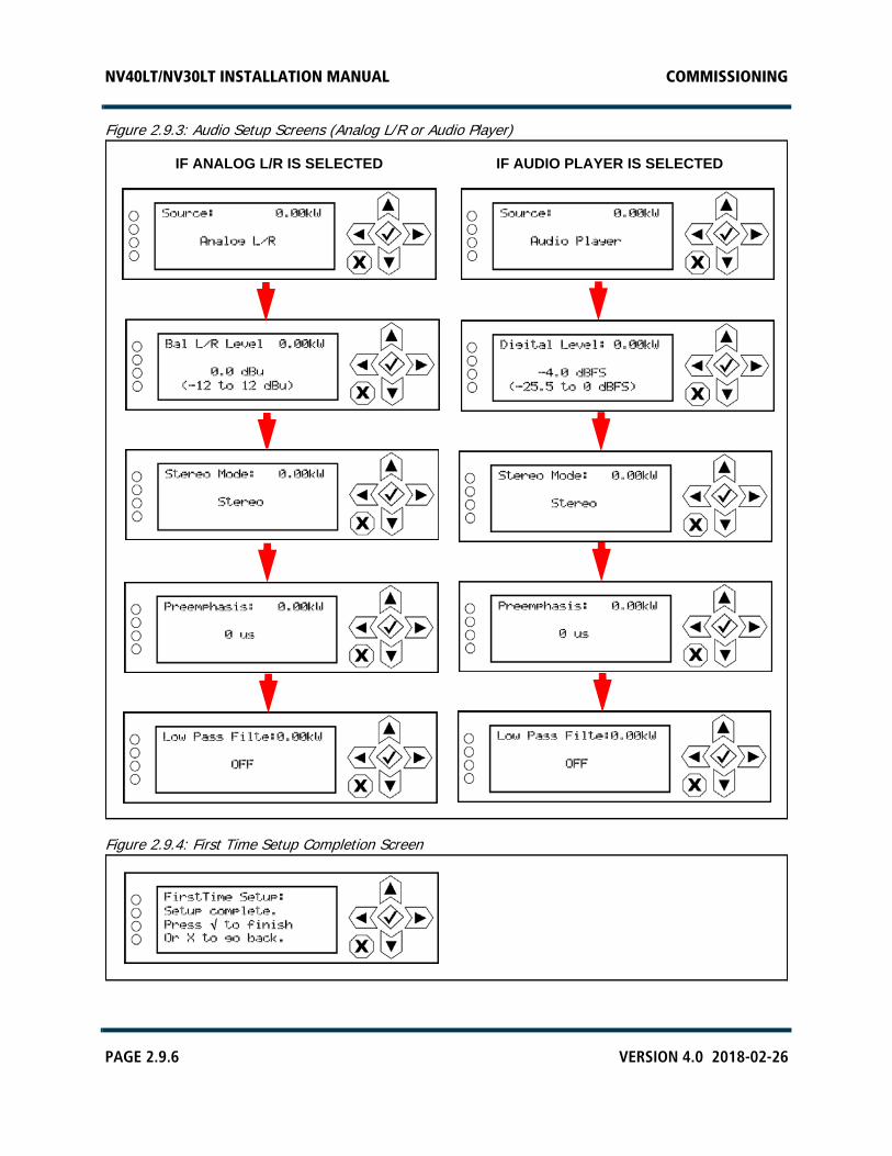
3. When selecting the audio source from the initial start-up screens, there are four options - AES, MPX, Analog L/R and Audio Player. Use the up and down arrows to toggle between source options, then press the checkmark button to select the desired source. Continue to the next associated audio screens, noting they are different depending on the audio source type (see Figure 2.9.2 on page 2.9.5 or Figure 2.9.3 on page 2.9.6). Edit values using the up and down arrows, and select using the checkmark button. Press the X button to cancel a selection.
4. When the audio setup in Step 3 is complete, the front panel should display a setup completion screen (see Figure 2.9.4 on page 2.9.6). Press the cancel (X) button to go back to the editing screens. Press the checkmark button to finish the setup, which creates a new preset for the NV40LT/NV30LT (preset 1 or P1). The top level screen (see Figure 2.9.5 on page 2.9.7) will be displayed.
NV40LT/NV30LT INSTALLATION MANUAL COMMISSIONING
PAGE 2.9.4 VERSION 4.0 2018-02-26
Figure 2.9.1: First Time Setup Initial Screens
SET FREQUENCYPress up/down arrows to adjust.Defaults to 98.1 MHz.Press checkmark to save and continue. Press X to cancel.
SET OUTPUT POWERPress up/down arrows to adjust. Defaults to minimum power level. Press checkmark to save and continue. Press X to cancel.
SELECT AUDIO SOURCEPress up/down arrows to select AES, MPX, Analog L/R or Audio Player. Press checkmark to save and continue (see Figure 2.9.2 on page 2.9.5 or Figure 2.9.3 on page 2.9.6). Press X to cancel.
NV40LT/NV30LT INSTALLATION MANUAL COMMISSIONING
VERSION 4.0 2018-02-26 PAGE 2.9.5
Figure 2.9.2: Audio Setup Screens (AES or MPX)
IF AES IS SELECTED IF MPX IS SELECTED
NV40LT/NV30LT INSTALLATION MANUAL COMMISSIONING
PAGE 2.9.6 VERSION 4.0 2018-02-26
Figure 2.9.3: Audio Setup Screens (Analog L/R or Audio Player)
Figure 2.9.4: First Time Setup Completion Screen
IF ANALOG L/R IS SELECTED IF AUDIO PLAYER IS SELECTED
NV40LT/NV30LT INSTALLATION MANUAL COMMISSIONING
VERSION 4.0 2018-02-26 PAGE 2.9.7
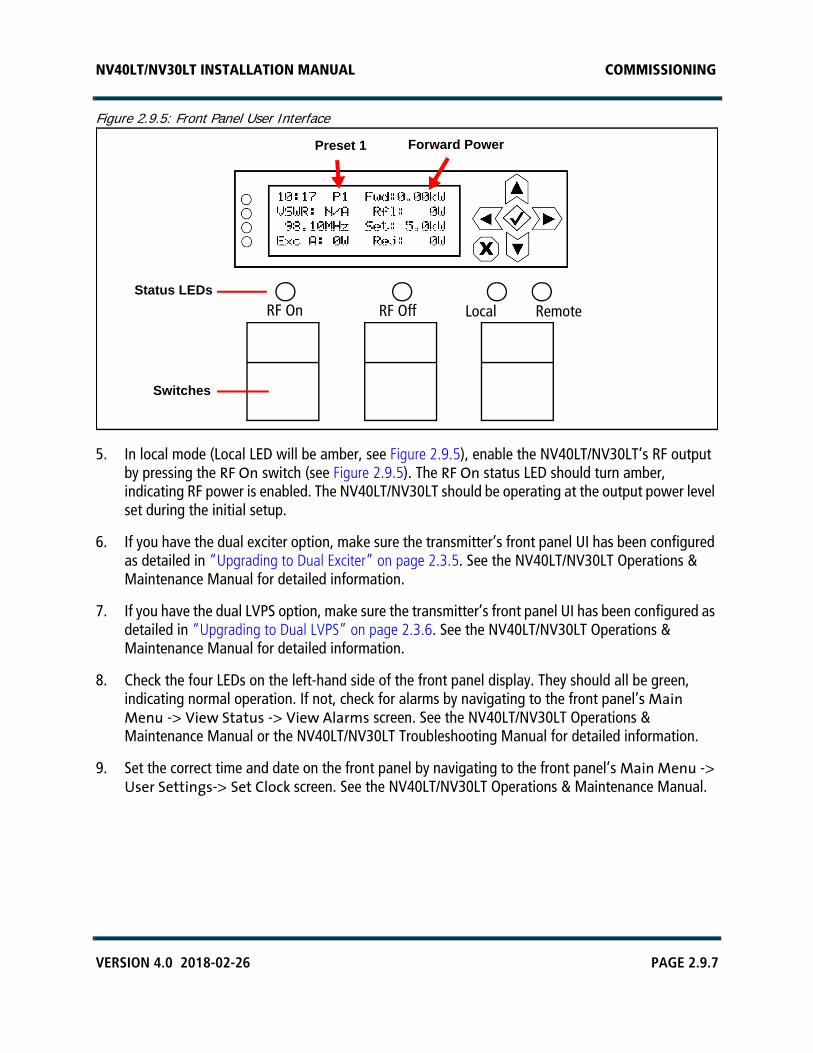
Figure 2.9.5: Front Panel User Interface
5. In local mode (Local LED will be amber, see Figure 2.9.5), enable the NV40LT/NV30LT’s RF output by pressing the RF On switch (see Figure 2.9.5). The RF On status LED should turn amber, indicating RF power is enabled. The NV40LT/NV30LT should be operating at the output power level set during the initial setup.
6. If you have the dual exciter option, make sure the transmitter’s front panel UI has been configured as detailed in “Upgrading to Dual Exciter” on page 2.3.5. See the NV40LT/NV30LT Operations & Maintenance Manual for detailed information.
7. If you have the dual LVPS option, make sure the transmitter’s front panel UI has been configured as detailed in “Upgrading to Dual LVPS” on page 2.3.6. See the NV40LT/NV30LT Operations & Maintenance Manual for detailed information.
8. Check the four LEDs on the left-hand side of the front panel display. They should all be green, indicating normal operation. If not, check for alarms by navigating to the front panel’s Main Menu -> View Status -> View Alarms screen. See the NV40LT/NV30LT Operations & Maintenance Manual or the NV40LT/NV30LT Troubleshooting Manual for detailed information.
9. Set the correct time and date on the front panel by navigating to the front panel’s Main Menu -> User Settings-> Set Clock screen. See the NV40LT/NV30LT Operations & Maintenance Manual.
Preset 1 Forward Power
RF On RF Off Local RemoteStatus LEDs
Switches

NV40LT/NV30LT INSTALLATION MANUAL COMMISSIONING
PAGE 2.9.8 VERSION 4.0 2018-02-26
Going On-Air
IMPORTANT! Before going on the air, if you want the safety interlocks to operate properly, the shorting jumpers installed in “Pre-Commissioning Tasks” on page 2.9.2, Step 4 should be removed.
1. Turn off the power using the ac disconnect switch, if one is being used, or else at the ac source.
2. Connect the transmitter's RF output to an antenna system (or verify that the current connection is intact).
3. Turn the transmitter’s ac power back on.
4. Use the front panel UI to begin transmitter operations. For detailed instructions, refer to the NV40LT/NV30LT Operating and Maintenance Manual.
Set for desired power level.
Press the front panel’s RF On pushbutton switch.
Select the desired exciter as main, if applicable.
WARNING! If a jumper is placed between the INTLK inputs [pins 19 and 20 of the controller’s REMOTE I/O-A connector (A1J2A) or TB1-1 and 2 on the optional remote interface PWB], safety features controlled by the external interlocks will be disabled. A fail-safe method of alerting personnel to this fact should be implemented. Voltages which are dangerous to life will be present on the RF output stages and the antenna system if the transmitter is turned on.
NV40LT/NV30LT INSTALLATION MANUAL COMMISSIONING
VERSION 4.0 2018-02-26 PAGE 2.9.9
Network Setup
If you wish to remotely control the transmitter via a network or directly through a laptop, configure your network parameters as follows:
1. Verify that the networking (DHCP on or off) decisions outlined in Section 2, “Pre-installation tasks” of the Pre-Installation Manual have been made. To use DHCP, you must have a visible DHCP server on your network. If you are not planning to use DHCP (i.e., your network does not have a DHCP server), you must obtain an IP address and netmask from your network administrator as well as gateway and nameserver(s) as applicable.
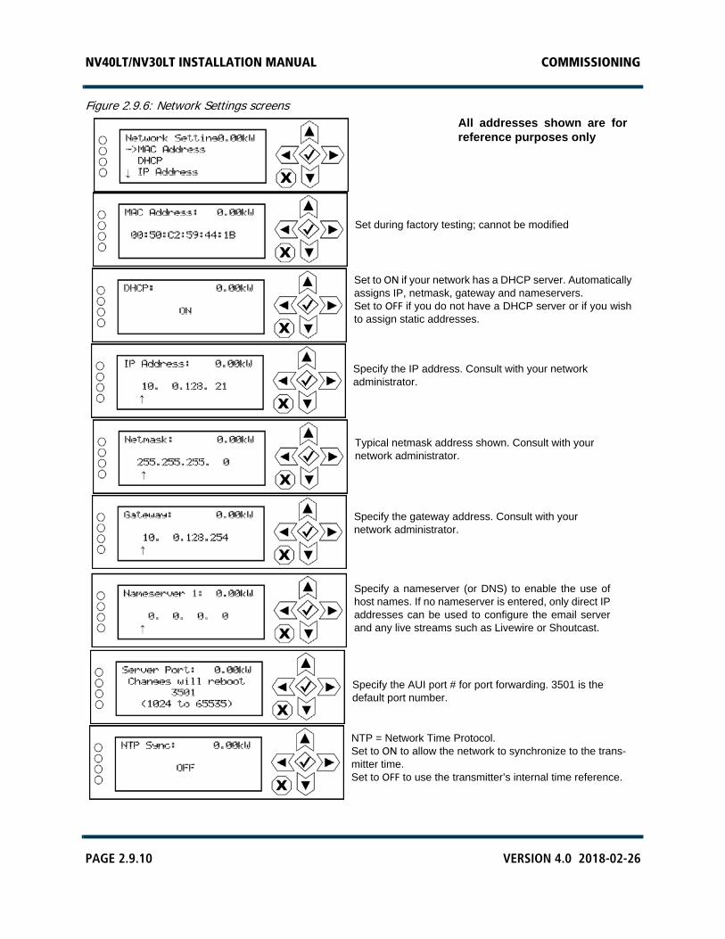
2. From the front panel UI, go the Main Menu -> User Settings -> Network Settings screen (see Figure 2.9.6 on page 2.9.10).
3. Ensure your network or laptop is connected to the LAN (A1J8A) connector on the rear of the controller (A4) or to the LAN connector (J1) on the optional remote interface PWB, if installed (see Section 2.8, “Installing Control/Monitor Wiring”).
4. If your network has a DHCP server and DHCP is set to ON (factory default), IP addresses will be automatically assigned. Verify this has occurred by viewing the IP Address and Netmask address sub-menus (Gateway and Nameserver addresses are optional; view as applicable). The MAC Address field cannot be modified.
5. If your network does not have a DHCP server or you wish to assign static IP addresses (i.e., direct connection with a laptop), set DHCP to OFF. Enter the appropriate addresses in the IP Address, Netmask, Gateway and Nameserver sub-menus, as applicable.
NOTE: Refer to “Network Setup” on page 3.2.85 of the Operations and Maintenance Manual for more information.
6. Once you have established an IP address, you can login to the NV40LT/NV30LT’s advanced user interface (AUI), which allows you to remotely control and monitor the NV40LT/NV30LT. See the “Operating the Transmitter” section of the Operations and Maintenance Manual for detailed AUI information.
NV40LT/NV30LT INSTALLATION MANUAL COMMISSIONING
PAGE 2.9.10 VERSION 4.0 2018-02-26
Figure 2.9.6: Network Settings screens
Set during factory testing; cannot be modified
Set to ON if your network has a DHCP server. Automaticallyassigns IP, netmask, gateway and nameservers.Set to OFF if you do not have a DHCP server or if you wishto assign static addresses.
All addresses shown are forreference purposes only
Specify a nameserver (or DNS) to enable the use ofhost names. If no nameserver is entered, only direct IPaddresses can be used to configure the email serverand any live streams such as Livewire or Shoutcast.
Typical netmask address shown. Consult with yournetwork administrator.
Specify the AUI port # for port forwarding. 3501 is thedefault port number.
NTP = Network Time Protocol.Set to ON to allow the network to synchronize to the trans-mitter time.Set to OFF to use the transmitter’s internal time reference.
Specify the IP address. Consult with your networkadministrator.
Specify the gateway address. Consult with yournetwork administrator.

NV40LT/NV30LT INSTALLATION MANUAL COMMISSIONING
VERSION 4.0 2018-02-26 PAGE 2.9.11
Configuring an External UPS
If the UPS Interface option was installed, perform the following steps to configure the transmitter to recognize the external UPS.
To view the UPS Installed screen, select System Settings > HW Config > UPS Installed from the Main Menu. Set to “YES”.

NV40LT/NV30LT INSTALLATION MANUAL COMMISSIONING
PAGE 2.9.12 VERSION 4.0 2018-02-26

NV40LT/NV30LT INSTALLATION MANUAL PARTS AND TOOLS
VERSION 4.0 2018-02-26 PAGE 2.10.1
SECTION 2.10: PARTS AND TOOLS
This section describes parts associated with the NV40LT/NV30LT transmitter, and tools needed during installation and routine operation. Topics include:
Parts Supplied by Nautel - see page 2.10.2
Parts Not Supplied by Nautel - see page 2.10.2
Parts Ordering - see page 2.10.2
Module Exchange Program - see page 2.10.3
Tools for Installation - see page 2.10.3
Contacting Nautel
You can reach Nautel to order parts or for technical assistance at:
Nautel Limited10089 Peggy’s Cove RoadHackett’s Cove, NS Canada B3Z 3J4Phone: +1.877.628.8353 (Canada/US) +1.902.823.5100 (International)
Fax: +1.902.823.3183
Email: [email protected]
Web: www.nautel.com
NV40LT/NV30LT INSTALLATION MANUAL PARTS AND TOOLS
PAGE 2.10.2 VERSION 4.0 2018-02-26
Parts Supplied by Nautel
Ancillary Parts Kit
An ancillary parts kit is shipped with the NV40LT/NV30LT. This kit contains items needed during the installation process. The kit includes toroids, spare fuses, screws and miscellaneous hardware.
Documentation
See “NV40LT/NV30LT Transmitter Manuals” in the “About this Manual” section of the Pre-Installation Manual.
Parts Not Supplied by Nautel
Some parts and materials required to complete installation are not supplied by Nautel. The parts you need vary with the installation requirements. The list of parts you normally provide yourself during installation include:
A suitable 50 RF output coaxial cable, terminated by the proper connector (e.g., field flange), complete with center male connector (e.g., bullet) at the transmitter end.
All external control and monitor wiring, including the associated terminating devices, conduit and conduit clamps.
All electrical power cables, including conduit, terminating devices, and conduit clamps.
Special tools, if required (e.g., torque wrench).
Parts Ordering
You can order replacement parts from the Customer Service Department, or directly from Nautel through the Nautel website.
NV40LT/NV30LT INSTALLATION MANUAL PARTS AND TOOLS
VERSION 4.0 2018-02-26 PAGE 2.10.3
Module Exchange Program
Nautel offers a module exchange program for customers who require expedited servicing and replacement of faulty modules. The module exchange program provides immediate replacement of failed modules with refurbished modules.
The replacement module is shipped to the customer as soon as the customer reports the failure. The customer then returns the failed module to Nautel using the same shipping package.
Tools for Installation
The tools you need during transmitter installation include the following:
Digital voltmeter (recommend 1000 V, CAT-III rating)
Phillips screwdrivers, sizes #1 and #2
Pliers
Wire cutters
Panel punch (Greenlee, etc.) for suitable size cable entry hole, as desired
Hex wrenches (Allen keys)
Torque wrench with hex adapter, capable of 500 in-lbs (56.5 N-m) (for ac input terminal block)
Metric and Imperial socket set up to 24 mm (15/16 inch)
Metric and Imperial wrench set up to 25 mm (1 inch)
Electrician’s knife

NV40LT/NV30LT INSTALLATION MANUAL PARTS AND TOOLS
PAGE 2.10.4 VERSION 4.0 2018-02-26
NV40LT/NV30LT INSTALLATION MANUAL PRE-INSTALLATION / INSTALLATION ASSISTANCE
VERSION 4.0 2018-02-26 PAGE 2.11.1
SECTION 2.11: PRE-INSTALLATION / INSTALLATION ASSISTANCE
Nautel provides a number of support options to help you during pre-installation planning and preparation:
Pre-Installation Consulting
Installation and Commissioning Service
Online Documentation - see page 2.11.2
On-Site Support - see page 2.11.3
Training - see page 2.11.3
Standard Warranty - see page 2.11.4
Extended Warranties - see page 2.11.7
Pre-Installation Consulting
Nautel field support specialists are available to answer questions and work with you to ensure that your site will be ready for the installation of your NV40LT/NV30LT transmitter. For support, contact Nautel Customer Service and request assistance (“On-Site Support” on page 2.11.3).
Installation and Commissioning Service
Nautel offers an installation and commissioning service to customers who want assistance with configuring and commissioning a new Nautel transmitter. After the customer completes the transmitter assembly and installation, Nautel technical personnel will spend up to three days on-site to help make the ac power, RF and remote connections, and to assist with the configuration and testing of Nautel equipment.
The customer is responsible for ensuring that the following stages of installation have been completed, prior to the arrival of Nautel personnel:
Ac power wiring for the transmitter has been installed and connected at the transmitter and at the breaker panel or the building’s service entrance.
NV40LT/NV30LT INSTALLATION MANUAL PRE-INSTALLATION / INSTALLATION ASSISTANCE
PAGE 2.11.2 VERSION 4.0 2018-02-26
The customer has prepared the RF coaxial cable – used to connect the transmitter to the antenna – and installed the required connector. The customer has also installed the RF coaxial cable in place and connected it to the antenna, while leaving the transmitter end of the cable unconnected.
Where required, all remote control and monitoring cables have been installed and connected to the station equipment (e.g., modulation monitor, frequency monitor, and power meter).
The site has been made ready for the equipment, and adequate protection against lightning and lightning-induced transients has been provided.
The transmitter has been unpacked, closely checked for any damage caused by shipping, and then assembled.
The following test equipment has been made available at the site:
Two-channel oscilloscope (with probes)
Audio signal generator
Distortion analyzer
Spectrum analyzer
Modulation monitor
Frequency counter
50 test load (rated for 150% of carrier power, VSWR less than 1.1:1)
Nautel’s service representative takes full responsibility for commissioning the transmitter, validating all external interfaces (i.e., the ac supply, RF output, remote control and monitoring equipment) and checking out the equipment prior to activation. The service representative turns on the transmitter, performs all adjustments and set-up procedures, and carries out proof of performance tests at the site. These tests ensure that the transmitter is operating normally in compliance with its specifications. The service representative also provides a demonstration and a short explanation of the operation of the transmitter. Finally, the customer signs an Acceptance of Installation Certificate that provides feedback to Nautel regarding the commissioning service.
Online Documentation
Nautel provides documentation online to customers, letting you familiarize yourself with specifications, operation, maintenance and troubleshooting prior to the delivery of your equipment. Documentation is also provided on CDROM and in paper binders that are delivered with the transmitter.

NV40LT/NV30LT INSTALLATION MANUAL PRE-INSTALLATION / INSTALLATION ASSISTANCE
VERSION 4.0 2018-02-26 PAGE 2.11.3
On-Site Support
If you require on-site assistance, Nautel’s field support specialists can help you prepare your site and ensure that your NV40LT/NV30LT transmitter installation can proceed as quickly as possible. For more information about on-site support, including scheduling and pricing, contact Nautel Customer Service:
Telephone: +1.902.823.5100
Fax: +1.902.823.3183
Email: [email protected]
After business hours (Atlantic time or Eastern time in North America), requests sent by fax or email will be acknowledged within one working day.
Training
Nautel's SBE-certified broadcast training programs satisfy your day-to-day knowledge requirements. Students participating in Nautel's broadcast transmitter or RF basics training programs earn one SBE credit for each completed day of training.
Nautel’s comprehensive selection of training programs will help customer staff develop valuable skill sets, reduce downtime, and make the most of the customer’s technology investment.
Nautel training programs are made up of individual modules that can be 'mixed and matched' to meet the customer’s specific training needs. All Nautel training courses are available at the Nautel Training Centre. Training can also be provided at the customer’s facility, and training the customer’s technical staff on the customer’s transmitter.
All training courses at the Nautel Training Centre combine classroom and hands-on laboratory work to ensure a balanced learning experience.
Nautel training courses feature:
Limited class sizes to ensure maximum student participation and access to equipment
Emphasis on need-to-know, day-to-day knowledge
Labs that focus on the tasks most often performed at the transmitter site
Many of our classes also include diagnostic lab exercises.

NV40LT/NV30LT INSTALLATION MANUAL PRE-INSTALLATION / INSTALLATION ASSISTANCE
PAGE 2.11.4 VERSION 4.0 2018-02-26
Standard Warranty
Nautel guarantees all mechanical and electrical parts of Nautel Transmitters for a period of forty-eight months, and all other Nautel manufactured equipment (including Importers and Exporters) for a period of twelve months from date of shipment, provided the equipment has been installed, operated and maintained in accordance with Nautel’s recommendations, and the equipment has not been misused, neglected or modified. Nautel's liability is limited, at the absolute discretion of Nautel, to repairing or replacing returned equipment that to the satisfaction of Nautel has been found defective.
Warranty for third-party items is provided by the Original Equipment Manufacturer. Exercise of such warranty shall be between the Buyer and the Third-Party.
Warranty for third-party items is provided by the Original Equipment Manufacturer. Exercise of such warranty shall be between the Buyer and the Third-Party.
1. Properly qualified technical personnel must install, maintain, and repair the equipment in accordance with Nautel recommendations and good engineering practice.
2. A "Part Failure" shall be deemed to have occurred when the part has become defective, or does not have the characteristics required for the specified equipment performance:
a. when the equipment is operated within the design parameters, and
b. when the equipment is installed and adjusted according to Nautel's prescribed procedures as stated in the instruction manual.
3. Nautel shall provide replacements for all "Parts" to the Buyer when they become defective during the warranty period, and upon the return of the defective part. Replacement parts warranty to be 90 days or end of original warranty; whichever comes first.
4. If the Buyer receives a replacement module, as part of Nautel's module exchange program, the old module must be returned to Nautel within 30 days of receipt of the new module, at the buyers expense. If the old module is not received after 30 days, the customer will be invoiced. The buyer is responsible for installing the replacement/repaired module in the transmitter.
5. In the event that a "Part" fails during the warranty period and causes damage to a subassembly which cannot be readily repaired in the field, the entire subassembly so damaged may be returned to Nautel for repair. The repairs will be made without charge to the Buyer.
6. Written authorization must be obtained before returning any equipment or goods for any reason. Equipment or goods returned under this warranty shall be delivered to Nautel's premises at the Buyer's expense. Where no-charge warranty replacements or repairs are provided under items 2, 3, 4, or 5, Nautel will pay that part of the shipping costs incurred in returning the part/assembly to the Buyer. Note: the Buyer is responsible for any and all import fees, duties or taxes.

NV40LT/NV30LT INSTALLATION MANUAL PRE-INSTALLATION / INSTALLATION ASSISTANCE
VERSION 4.0 2018-02-26 PAGE 2.11.5
7. Nautel does not warrant or guarantee, and will not be liable for:
a. defects or failures caused in whole or in part by abuse, misuse, unauthorized repair attempts, unauthorized alteration or modification of the equipment;
b. equipment built to customer specifications that is later found not to meet customer needs or expectation;
c. performance of equipment when it is used in combination with other equipment not purchased, specified, or approved by Nautel;
d. damages and performance limitations due to outside forces such as lightning, excessive heat or cold, excessive ac surges or high corrosive environments;
e. changes made by personnel other than Nautel authorized personnel, including charges incurred; and
f. for any costs for labor performed by the customer without Nautel's prior written approval.
8. Nautel does not warrant that software:
a. is free or errors, bugs or defects;
b. will be compatible with third party software;
c. results, output or data provided through or generated by the software are accurate, complete, or reliable; and
d. errors found will be corrected.
9. Nautel shall have the right and shall be provided full access to investigate whether failures have been caused by factors beyond its control.
10. In no event shall Nautel be liable for any consequential damages arising from the use of this equipment.
11. This warranty is in lieu of all other express warranties of Nautel, whether express or implied, and Nautel does not assume, nor is any other person authorized to assume on Nautel's behalf, any other obligation or liability.
12. Third party items ordered, the guarantee/warranty of these items will be from the manufacturer of these items. Exercise of such warranty shall be between the Buyer and the third party provider.
13. Nautel provides telephone and email support for its products for the life of the product at no charge. After the warranty period, parts and on-site support for the equipment are offered at a rate to be determined upon request.

NV40LT/NV30LT INSTALLATION MANUAL PRE-INSTALLATION / INSTALLATION ASSISTANCE
PAGE 2.11.6 VERSION 4.0 2018-02-26
Technical Assistance
Nautel's field service department provides telephone technical assistance on a 24 hour, seven days a week basis. Requests by other media (fax or e-mail) will be responded to the next working day if received after Nautel's normal working hours. Contact the appropriate field service centre:
Nautel Limited10089 Peggy’s Cove RoadHackett’s Cove, NS Canada B3Z 3J4Phone: +1.902.823.3900 orToll Free: +1.877.6NAUTEL (6628835) (Canada & USA only)Fax: +1.902.823.3183
Nautel Inc. 201 Target Industrial Circle Bangor, Maine USA 04401 Phone: +1.207.947.8200 Fax: +1.207.947.3693
Customer Service (24 hour support) +1.877.628.8353 (Canada & USA only)
+1.902.823.5100 (International)
Email: [email protected]: www.nautel.com
Module Exchange Service
In order to provide Nautel customers with a fast and efficient service in the event of a problem, Nautel operates a factory rebuilt, module exchange service which takes full advantage of the high degree of module redundancy in Nautel equipment. This module exchange service is operated from Nautel's factory in Bangor, Maine and Hackett's Cove, Nova Scotia. These two locations allow us to provide a quick turn around service to keep our customers on the air. During the transmitter's warranty period, up to thirteen months from shipment, repair and exchange of modules is at no charge to the customer. When the warranty has expired, a charge of 80% of the list price for all exchanged modules is made. If the faulty module is returned to Nautel within 30 days, a credit is issued reducing this charge by one half to 40% of the list price. USA customers are required to contact our Bangor, Maine facility. Canadian and overseas customers should contact our Nova Scotia, Canada facility.
NV40LT/NV30LT INSTALLATION MANUAL PRE-INSTALLATION / INSTALLATION ASSISTANCE
VERSION 4.0 2018-02-26 PAGE 2.11.7
Equipment Being Returned to Nautel
For all equipment being returned to Nautel and all requests for repairs or replacements:
Obtain an RMA number from Nautel (you must have an RMA number to return equipment)
Mark the item as 'field return'
Mark the item with the RMA number assigned by Nautel
Address the item to the appropriate Nautel facility
Complete and accurate information regarding the equipment being returned will ensure prompt attention and will expedite the dispatch of replacements. Refer to the nameplate on the transmitter and/or the appropriate module/assembly to obtain name, type, part and serial number information. Refer to the parts list of this manual or the appropriate service instruction manual for additional ordering information.
The following information should accompany each request (* denotes minimum required information):
*Model and serial number of equipment
*Name of part/assembly
Serial number of part/assembly
*Complete reference designation of part/assembly
*Nautel's part number of part/assembly
*OEM's part number of part/assembly
Number of hours in use
Nature of defect
*Return shipping address
Extended Warranties
Nautel's standard four-year warranty provides excellent coverage and satisfies most customers’ needs. However, if you want extended coverage, Nautel offers one and two-year Extended Warranty Plans to cover electrical and mechanical repairs or replacements for all Nautel equipment.

NV40LT/NV30LT INSTALLATION MANUAL PRE-INSTALLATION / INSTALLATION ASSISTANCE
PAGE 2.11.8 VERSION 4.0 2018-02-26
Coverage
The Extended Warranty Plan includes:
A module exchange program for many common modules and circuit boards (North America only)
Toll-free hotline (North America only)
Necessary labor performed by Nautel authorized personnel to repair the product back to factory specifications
Necessary components
Modifications to correct performance problems
Return shipping
Details
Extended Warranty Plans must be purchased prior to the expiration of original four-year warranty.
One-year Extended Warranty Plans add an additional year (12 months) of coverage after the end of the customer’s standard four-year warranty. The two-year plan adds an additional two years (24 months).
Only repairs done at Nautel's facilities or by Nautel authorized personnel will be covered by the Extended Warranty Plans.
You must ship faulty products back to Nautel, prepaid, and in the original package or in a package that provides equivalent protection.
Nautel can choose to repair or replace equipment.
Purchasing a One or Two-Year Extended Warranty Plan
If the transmitter is still covered by its original four-year warranty period, you can contact Nautel by telephone, fax, mail, or email with the model number, serial number and date of purchase.
Once you purchase a Nautel Extended Warranty Plan, you receive an extended warranty plan certificate, plan number, and a toll-free number (North America only) to call for any service-related issues.
NV40LT/NV30LT INSTALLATION MANUAL PRE-INSTALLATION / INSTALLATION ASSISTANCE
VERSION 4.0 2018-02-26 PAGE 2.11.9
Using the Extended Warranty Plan
Contact Nautel's Canadian or U.S. service facility by phone, fax, or email as soon as a problem occurs. The following will be required when contacting Nautel:
Extended warranty plan number
Product model number
Serial number
Brief description of the problem
If Nautel’s service technicians are unable to solve the problem over the telephone, Nautel will give you an RMA number. You then return the module or circuit board to a Nautel service facility so that Nautel can provide a replacement. Do not ship a component back to Nautel until you have an RMA number.

NV40LT/NV30LT INSTALLATION MANUAL PRE-INSTALLATION / INSTALLATION ASSISTANCE
PAGE 2.11.10 VERSION 4.0 2018-02-26

NV40LT/NV30LT INSTALLATION MANUAL LIST OF TERMS
VERSION 4.0 2018-02-26 PAGE 2.12.1
SECTION 2.12: LIST OF TERMS
This section defines some of the terms that are used in Nautel documentation.
AES/EBU. Audio Engineering Society/European Broadcasting Union (AES/EBU) is the name of a digital audio transfer standard. The AES/EBU digital interface is usually implemented using 3-pin XLR connectors (the same type connector used in professional micros). One cable carries both left-channel and right-channel audio data to the receiving device.
AUI. The Advanced User Interface is the advanced remote control/monitoring feature that allows for extensive remote control and monitoring of the transmitter.
Cutback. A reduction in RF output power, caused by the occurrence of multiple shutbacks within a pre-defined period.
DHCP. Dynamic Host Carrier Protocol.
DSP. Digital Signal Processing.
EEPROM. Electrically Erasable Programmable Read-Only Memory.
Foldback. A reduction in RF output power, caused by adverse load conditions (high VSWR). No shutbacks or cutbacks have occurred.
LED. Light Emitting Diode (also referred to as lamp).
LVPS. Low Voltage Power Supply. A module or modules used in the ac-dc power stage that generates the low level dc supply voltage for the transmitter.
Preset. A setting that controls power level, frequency and audio parameters. The NV40LT/NV30LT allows you to pre-program multiple presets.
PWB. Printed Wiring Board.
Shutback. A complete, but temporary loss of RF output power, caused by any one of a variety of faults, including high VSWR, high reject load power, RF drive failure, or an open external interlock.
Shutdown. A complete and permanent loss of RF output power. Typically follows repeated cutback, foldback or shutback events.
Surge protection panel. An electrical panel that protects equipment from electrical surges in the ac power supply, antenna or site ground caused by lightning strikes.
UI. The User Interface is the front panel LCD screen that allows for extensive local control and monitoring of the transmitter.
VSWR. Voltage standing wave ratio. This is an expression of the ratio of reverse voltage to forward voltage on the feedline and antenna system. An ideal VSWR of 1:1 provides maximum transmitter-antenna efficiency.

NV40LT/NV30LT INSTALLATION MANUAL LIST OF TERMS
PAGE 2.12.2 VERSION 4.0 2018-02-26


NV40LT/NV30LT INSTALLATION MANUAL
Document: NHB-NV30LT-NV40LT-INS
Issue: 2018-02-26
Nautel Limited10089 Peggy’s Cove RoadHackett’s Cove, NS Canada B3Z 3J4
Toll Free: +1.877.6NAUTEL (662.8835) (Canada & USA only) or
Phone: +1.902.823.3900 orFax: +1.902.823.3183
Nautel Inc. 201 Target Industrial Circle Bangor, Maine USA 04401
Phone: +1.207.947.8200 Fax: +1.207.947.3693
Customer Service (24-hour support) +1.877.628.8353 (Canada & USA only)+1.902.823.5100 (International)
Email: [email protected]: www.nautel.com
© Copyright 2018 NAUTEL. All rights reserved.