Embed Size (px)
Citation preview
1
The following slides are designed to give you good understanding of the KM sequence of operation. You will find the sequence explained in two ways the first is a basic explanation that goes along with a flow chart that guides you through the complete sequence of operation. The slides that follow the flow chart give you specific information on each step of the operation.
The sequence of operation for all later model KM Units (“M”, “S” and “B”series KM units) is basically the same. A complete understanding of thesequence will enable the service technician to troubleshoot any KM model that he or she is called to work on. In the next few slides we will discuss the four steps involved in the sequence of operation on the KM units.

2
Peachtree City is home office for America located about 30 miles south of the Atlanta airport this is were all KM cubers as well as Flakers are built.
Griffin built in 2001 we started building Reach-In’s; Griffin is about 30 miles East of PTC, Griffin is also where the Service Parts are as well as warehousing.
Contacting Hoshizaki: 1-800 number is available from 8-5 Eastern and after hours., holidays, and weekends.
Pay attention to prompts when calling in there are two ways:
1. Leave a message this message will be emailed to Tech. support email box and this box has to be cleared everyday before going home, you will get a call back.
2. Wait for the next available TA (please wait do not hang up and call back as that will put you to the back of the line, as well do not call and hang up several times as this does not give good data in our continuing effort to cut wait time to a minimum.)
Hoshizaki website :Free information, instruction, service, and parts manuals all online as well as Tech -Tips (articles written by TA’s on service and parts related subjects), service bulletins, warranty validation, as well as registration.
QR code: As of Jan. 1 2012 equipment shipping out of Peachtree City has QR codes on the machine for model and serial information and will take the servicer directly to the manuals for that particular piece of equipment.

3
The following is a brief explanation of the sequence of operation for the KM cuber using either the “Alpine”, “E” or “G” control board. For more detailed information please see additional sequence slides.
NOTE: When power is supplied to the “E” Control board there is a 5 second and the “G” board has a 10 second delay at start-up.
1. 1 Minute Fill CycleThe unit always starts in the 1 minute fill cycle. When power is applied to the unit the water valve is energized and the fill period begins. After 1 minute the board checks for a closed float switch. If the float switch is closed the harvest cycle begins. If not, the unit will not start without adequate water in the sump. This serves as a low water safety shut off. The water valve will remain energized through additional 1 minute cycles until water enters the sump and the float switch closes.
2. Initial Harvest CycleThe compressor starts, hot gas valve opens, water valve remains open and harvest begins. As the evaporator warms, the thermistor located on the suction line checks for a 48° F. temperature. When 48° F. is reached, the harvest is turned over to the adjustable control board defrost timer which is factory set for normal conditions. This adjustment can vary the defrost timer from 1 to 3 minutes.
3. Freeze CycleAfter the timer terminates the harvest cycle, the hot gas and water valves close, and the ice production cycle starts. For the first 5 minutes the controller board will not accept a signal from the float switch. This 5 minute minimum freeze acts as a short cycle protection. At the end of 5 minutes the float switch assumes control. As ice builds on the evaporator the water level in the sump lowers. The freeze continues until the float switch opens and terminates ice production.
4. Harvest Pump OutWhen the float switch opens and signals the completion of the freeze cycle, the harvest cycle begins. The hot gas valve opensand the compressor continues to run. The drain timer starts counting the 10/20 second pump out. The water pump stops for 2 seconds and reverses, taking water from the bottom of the sump and forcing pressure against the check valve seat allowing water to go through the check valve and down the drain. At the same, time water flows through the small tube to power flush the float switch. When the drain timer stops counting, the pump out is complete. Pump out always occurs on the 2nd harvest after startup. The Alpine control board allows for adjustment for pump out to occur every cycle, or every 2nd, 5th or 10th cycle from this point.
5. Normal Harvest CycleThe water valve opens to allow water to assist the harvest. As the evaporator warms, the thermistor reaches 48° F. The control board receives the thermistor signal and starts the defrost timer. The water valve is open during harvest (defrost) for a maximum of 6 minutes or the length of harvest, whichever is shorter. When the defrost timer completes its count down, the defrost cycle is complete and the next freeze cycle starts. The unit continues to cycle through 3, 4 and 5 sequence until the bin control senses ice and shuts theunit down.

4
This connector diagram shows the standard color code and component layout.
Use it as a guide for circuit diagnosis.

5
All newer model machines (“M”, “S” and “B” series KM units) begin the sequence of operation in the one- minute fill cycle. This cycle will occur every time the unit starts from a “cold start” Example: The toggle switch being turned on, the power being restored to the unit, safety reset or when the bin control calls for ice. During this cycle the water valve energizes and begins to fill the reservoir by bringing water through the water valve and down through the center of each evaporator plate.
The unit uses the one- minute fill cycle to accomplish two functions. The first is to offer a low water safety or probably more accurately a “No Water” safety. The “No Water” safety is accomplished by the control board checking the status of the float switch after 60 seconds. If the float switch closes then the unit will start the next cycle (Initial harvest). If the float switch remains open due to no water being supplied to the unit, the unit will go through another one minute fill. The unit will continue one-minute fill cycle with the board checking the float switch every 60 seconds, until the float closes. The unit can stay in this position indefinitely until water is restored, closing the float switch. This offers a continuous “No Water” safety to prevent the unit from starting with no water in the reservoir. This protects the water pump from possible damage caused by the pump running dry or damage to the compressor due to refrigerant flood back.
The second function the one- minute fill provides is a short cycle protection. Whenever the unit is shutdown due to the power supply being interrupted or the bin control being satisfied, the unit must return to the one-minute fill. This prevents the compressor from stopping and re-starting rapidly, which could cause damage.
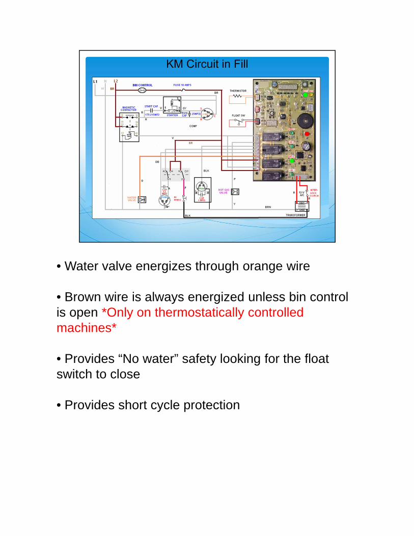
• Water valve energizes through orange wire
• Brown wire is always energized unless bin control is open *Only on thermostatically controlled machines*
• Provides “No water” safety looking for the float switch to close
• Provides short cycle protection
7
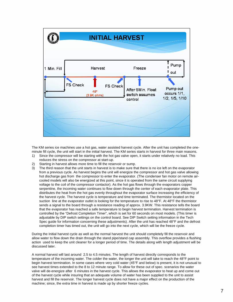
The KM series ice machines use a hot gas, water assisted harvest cycle. After the unit has completed the one-minute fill cycle, the unit will start in the initial harvest. The KM series starts in harvest for three main reasons. 1) Since the compressor will be starting with the hot gas valve open, it starts under relatively no load. This
reduces the stress on the compressor at start-up. 2) Starting in harvest allows more time to fill the reservoir or sump. 3) The third reason that the unit starts in harvest is to make sure that there is no ice left on the evaporator
from a previous cycle. As harvest begins the unit will energize the compressor and hot gas valve allowing hot discharge gas from the compressor to enter the evaporator. (The condenser fan motor on remote air-cooled models will also be energized at this point, since it is operated from the same circuit supplying voltage to the coil of the compressor contactor). As the hot gas flows through the evaporators copper serpentine, the incoming water continues to flow down through the center of each evaporator plate. This distributes the heat from the hot gas evenly throughout the evaporator surface increasing the efficiency of the harvest cycle. The harvest cycle is temperature and time terminated. The thermistor located on the suction line at the evaporator outlet is looking for the temperature to rise to 48°F. At 48°F the thermistor sends a signal to the board through a resistance reading of approx. 3.9KW. This resistance tells the board that the evaporator has reached a safe temperature to begin harvest termination. Harvest termination is controlled by the “Defrost Completion Timer”, which is set for 60 seconds on most models. (This timer is adjustable by DIP switch settings on the control board. See DIP Switch setting information in the Tech Spec guide for information concerning these adjustments). After the unit has reached 48°F and the defrost completion timer has timed out, the unit will go into the next cycle, which will be the freeze cycle.
During the Initial harvest cycle as well as the normal harvest the unit should completely fill the reservoir and allow water to flow down the drain through the stand pipe/stand cap assembly. This overflow provides a flushing action used to keep the unit cleaner for a longer period of time. The details along with length adjustment will be discussed later.
A normal harvest will last around 2.5 to 4.5 minutes. The length of harvest directly corresponds to the temperature of the incoming water. The colder the water, the longer the unit will take to reach the 48°F point to begin harvest termination. In some cases where very cold water (45°F and below) is present, it is not unusual to see harvest times extended to the 8 to 12 minute range. To allow for these out of spec. scenarios the water valve will de-energize after 6 minutes in the harvest cycle. This allows the evaporator to heat up and come out of the harvest cycle while insuring that an adequate volume of water has been supplied to the unit to assist harvest and fill the reservoir. The longer harvest cycle does not have a major effect on the production of the machine; since, the extra time in harvest is made up by shorter freeze cycles.
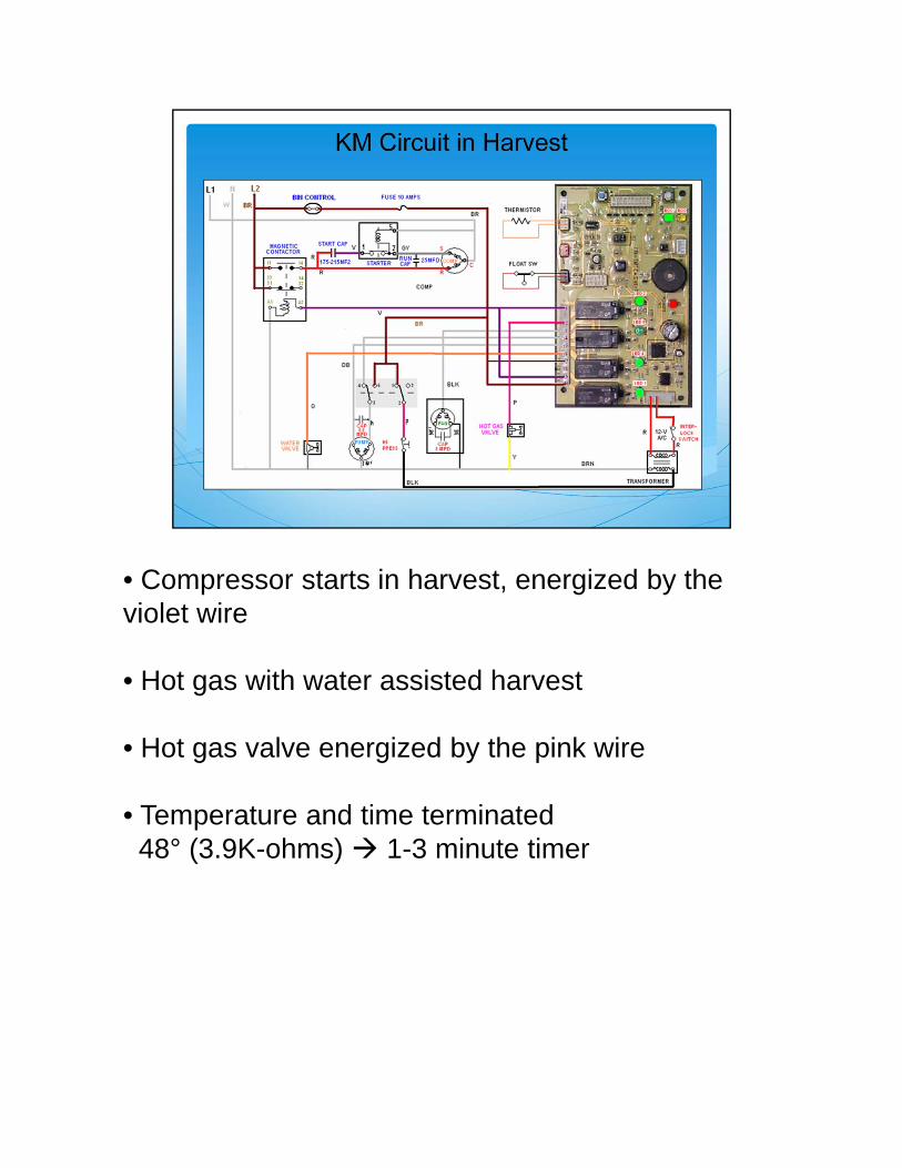
• Compressor starts in harvest, energized by the violet wire
• Hot gas with water assisted harvest
• Hot gas valve energized by the pink wire
• Temperature and time terminated 48° (3.9K-ohms) 1-3 minute timer

9
After the unit has completed the harvest cycle it will begin the freeze cycle. At this point the hot gas valve and water valve will de-energize and the water pump and the fan motor on self-contained air-cooled machines will energize. On some models a liquid line solenoid will also be energized during freeze. The freeze cycle will generally last from 25-45 minutes with the average being around 35 minutes. This depends on model and ambient and water conditions.
Termination of the freeze cycle is controlled by the float switch, which monitors water level. Sincethe KM series uses a batch weight system, the unit will not energize the water inlet valve during the freeze cycle. The unit will only fill with water during the fill and harvest cycle. Remember that the unit will only go through the one- minute fill after the unit starts from a cold start (After the bincontrol has been satisfied or a power interruption). During continuous ice making, the reservoir fills completely and overflows during the harvest cycle.
As the water pump re-circulates the water over the evaporator and ice begins to form, the water level in the reservoir will be reduced. When this level is low enough, the float switch will open sending the unit into the next cycle. There is a 5 minute short cycle protection built in to the control board that will prevent the unit from going into harvest within the first five minutes of the freeze cycle. This prevents the unit from short cycling between freeze and harvest.
When the float switch opens the unit will then go in to next cycle. This may be either the pump outor the harvest cycle depending on what number harvest cycle the unit is in.
There is an additional back- up safety built into the control board for maximum freeze time. Thistimer is adjustable however on most models it will be set at 50 or 60 minutes. If the unit has twoconsecutive maximum freeze times in row the unit will shut down on a manual reset 3 beep audible safety. For more information on this safety please see the Tech-Spec pocket guide or Tech Tip 150.
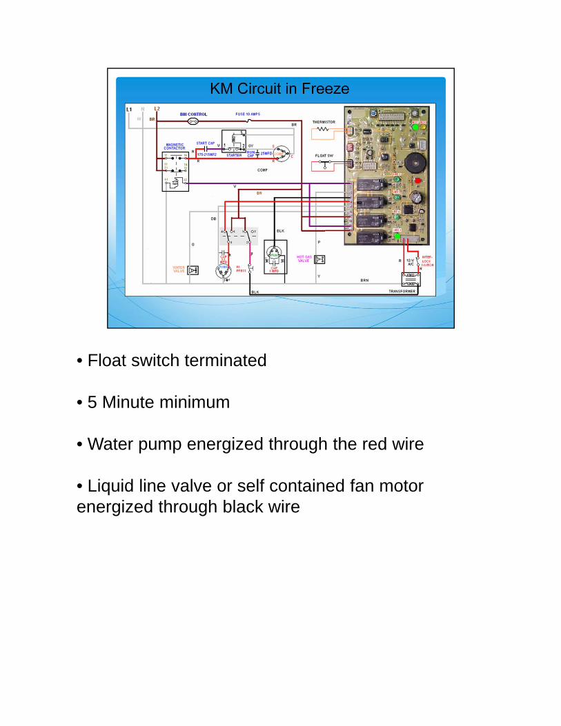
• Float switch terminated
• 5 Minute minimum
• Water pump energized through the red wire
• Liquid line valve or self contained fan motor energized through black wire
11
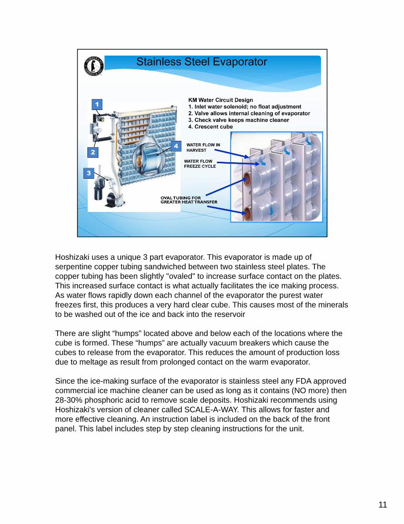
Hoshizaki uses a unique 3 part evaporator. This evaporator is made up of serpentine copper tubing sandwiched between two stainless steel plates. The copper tubing has been slightly "ovaled" to increase surface contact on the plates. This increased surface contact is what actually facilitates the ice making process. As water flows rapidly down each channel of the evaporator the purest water freezes first, this produces a very hard clear cube. This causes most of the minerals to be washed out of the ice and back into the reservoir
There are slight “humps” located above and below each of the locations where the cube is formed. These “humps” are actually vacuum breakers which cause the cubes to release from the evaporator. This reduces the amount of production loss due to meltage as result from prolonged contact on the warm evaporator.
Since the ice-making surface of the evaporator is stainless steel any FDA approved commercial ice machine cleaner can be used as long as it contains (NO more) then 28-30% phosphoric acid to remove scale deposits. Hoshizaki recommends using Hoshizaki's version of cleaner called SCALE-A-WAY. This allows for faster and more effective cleaning. An instruction label is included on the back of the front panel. This label includes step by step cleaning instructions for the unit.

12
Now, the unit has completed a one- minute fill cycle, approximately a 3.5 minute harvest cycleand a complete freeze cycle. The water has dropped to a level that the float switch will open andsend the unit in to the next cycle.
At the beginning of the harvest cycle the unit may go through the pump out cycle. This dependson what number harvest cycle the unit is beginning. The cycle frequency can be adjusted from1/1, 1/2, 1/5, 1/10. Note: The unit will not pump out on the initial harvest. The frequency countwill begin on the second harvest cycle. The factory setting is to pump out 1/10 harvest cycles, onmost models. The adjustment is done with the DIP switches on the control board. As mentionedearlier this information can be found in the Tech Spec guide.
When the pump out cycle is energized it will last either 10 or 20 seconds depending on themodel. The purpose of this cycle is to keep the unit cleaner by removing the minerals andsediment from the bottom of the sump tank. This pump out only removes the water that hasremained after a freeze cycle. The water inlet valve does not energize during this 10 or 20second period. You will notice that the Hot Gas Valve is energized at this point and begins towarm the evaporator plate.
On KM models, the water pump will stop for 2 seconds and then re-energize in the reverserotation. This reversing pulls the mineral laden water from the bottom of the sump forcing itthrough a mechanical check valve into the standpipe then down the drain.
The KML units operate a little different, these units use a solenoid valve instead of a mechanicalcheck valve and the water pump does not reverse. When the pump out cycle begins the unit willenergize the solenoid dump valve and restart the pump in the same direction for the 10 or 20second pump-out cycle. Since water will take the path of least resistance the mineral laden waterwill travel through the solenoid valve and down the drain, instead of going over the evaporator inits normal flow.

• KM models water pump reverses, pushing water through the drain.
• KML models dump valve opens allowing water to be pumped down drain.
• Adjustable frequency
• Blue wire energizes pump in reverse (KM) or pump out solenoid (KML)
• Pink wire energizes hot gas valve
We hope that this gives you a good understanding of the operation for the KM series units. If you have any questions concerning this or any other technical information please send e‐mail to [email protected] or call the Technical Support Department at 1‐800‐233‐1940.