Embed Size (px)
Citation preview

13.10.2021 ETH Zurich | Chair of Concrete Structures and Bridge Design | Advanced Structural Concrete 1
2 In plane loading –walls and beams
2.2 Stress fields with prestressing
13.10.2021 ETH Zurich | Chair of Concrete Structures and Bridge Design | Advanced Structural Concrete 1
2 In plane loading –walls and beams
2.2 Stress fields with prestressing
13.10.2021 ETH Zurich | Chair of Concrete Structures and Bridge Design | Advanced Structural Concrete 1
2 In plane loading –walls and beams
2.2 Stress fields with prestressing

2
Learning objectives
13.10.2021 ETH Zurich | Chair of Concrete Structures and Bridge Design | Advanced Structural Concrete 2
Within this chapter, the students are able to:
recognise the suitability of treating prestressing as equivalent forces for the analysis of 2D and 3D structures.
create simplified stress fields and strut-and-tie models including prestressing as anchorage and deviation forces.

13.10.2021 ETH Zurich | Chair of Concrete Structures and Bridge Design | Advanced Structural Concrete 3
2 In plane loading –walls and beams
2.2 Stress fields with prestressing
BasisRepetition from Stahlbeton II (Vorspannung)
13.10.2021 ETH Zurich | Chair of Concrete Structures and Bridge Design | Advanced Structural Concrete 3
2 In plane loading –walls and beams
2.2 Stress fields with prestressing
BasisRepetition from Stahlbeton II (Vorspannung)
13.10.2021 ETH Zurich | Chair of Concrete Structures and Bridge Design | Advanced Structural Concrete 3
2 In plane loading –walls and beams
2.2 Stress fields with prestressing
BasisRepetition from Stahlbeton II (Vorspannung)

Repetition from Stahlbeton II:
The maximum spans of reinforced concrete structures are limited due to crack formation and long-termdeformations (creep). Deformations become unacceptably large in the case of large slenderness, asrequired for long-span structures.
With prestressing, these problems can be solved by compensating the stresses caused by permanentloads - or part of them - by the anchorage and deviation forces of the prestressing. Prestressing is thus anessential element of long-span, slender and economical concrete structures. It was essential for thebreakthrough and success of concrete structures, especially in bridge construction.
There are two ways of taking prestressing into account in framed structures. They differ in the boundariesof the considered system. Each of these approaches has its advantages and disadvantages, anddepending on the particular problem, one or the other approach is more suitable.
Since the pre-strain (strains at initial prestressing) usually ensures that the prestressing steel yields atULS in bending, determination of the bending resistance is straightforward when considering prestressingas a residual stress state. It makes sense to take into account the residual forces Mps(P), Nps(P), Vps(P)(with P0 or P ) (even if this is not mandatory considering plastic redistribution of internal forces):
Considering the prestressing as anchorage, deviation and friction forces is useful for the verification ofthe stresses in cross-sections. A standard stress calculation (without pre-strain) can be carried out on thereinforced concrete cross-section under the loads incl. Mc(P), Vc(P), Nc(P). It is also advantageous fordeflection calculations (incl. creep) and the verification of structural safety in shear. Since the increase inprestressing force is neglected, the resistance of the prestressing is Vc(P ) (included in Vc(P) from staticprogram if prestressing is modelled accordingly). Note: If the verification of the structural safety in bendingis performed with the loads including Mc(P), Vc(P), Nc(P), only the increase in prestressing force (fpd p)may be taken into account in the bending resistance, not fpd (otherwise prestressing is considered twice).
Prestressing of framed structures (SB II)
• Prestressing = Controlled application of forces to the structure or building component
• Anchorage, deviation and friction forces act between the prestressing steel and the structural member without prestressingtendon.
• Prestressing generates a residual stress state and causes deformations of the structure.
• In statically indeterminate systems, restraint forces result from restrained deformations.
• The load-bearing behaviour of prestressed beams can be investigated analogously to passively reinforced structures by means of cross-sectional analyses. Note that the strain difference between prestressing steel and concrete is "frozen" during the injection of the prestressing duct.
• There are two alternative possibilities for treating prestressing:
• Both possibilities lead to the same result (with consistent application). The only difference are the boundaries of the system.
• Depending on the specific problem, one or the other option is more convenient.
13.10.2021 ETH Zurich | Chair of Concrete Structures and Bridge Design | Advanced Structural Concrete 4
Residual stress state acting on the entire structure or building component including the prestressing tendonAlso referred to as prestressing treated as resistance
Anchorage, deviation and friction forces acting on the structural member without prestressing tendonAlso referred to as prestressing treated as load

Repetition from Stahlbeton II:
If the entire structure is considered, including the prestressing tendon, the prestressing causes a residualstress state in each section. In statically indeterminate systems, the deformations corresponding to thisresidual stress state are not necessarily compatible with the configuration of boundary conditions andresidual forces Mps(P), Vps(P), Nps(P) result from the prestressing. These forces together with the externalloads (dead load, live loads, ...) should be taken into account as loads. The cross-sectional resistancecorresponds to the resistance of the entire cross-section including prestressing. This is why we speak of"prestressing treated as resistance".
Alternatively, one can consider the structure without the prestressing tendon. Anchorage, deviation andfriction forces act as a result of prestressing. This is why the term "prestressing treated as load" is used inthis context. The restraint forces acting on the entire structure are accounted for directly by determiningthe internal actions due to anchorage, deviation and friction forces and are thus included in the internalactions due to prestressing Mc(P), Vc(P), Nc(P).
Prestressing of framed structures (SB II)
Treatment of prestressing / definition of system under consideration (2)Entire structure / element
Prestressing causes a residual stress state in the cross-sections: The tensile force in the tendon is in equilibrium with the (compression) forces in the reinforced concrete section. The residual stress state corresponds to strains and curvatures deformations of the structure.
The internal actions contain only the restraint actions Mps(P), Vps(P), Nps(P). Actions on the total cross-section :
Structure / element without prestressing tendon
The prestressing corresponds to anchorage, deviation and friction forces acting on the structure without the tendon. These loads result in the so-called internal actions due to prestressing Mc(P), Vc(P), Nc(P) and deformations (compatible with the arrangement of supports).
The internal actions contain the total internal forces due to prestressing Mc(P), Vc(P), Nc(P). Actions on the cross-section without the prestressing the tendon:
13.10.2021 ETH Zurich | Chair of Concrete Structures and Bridge Design | Advanced Structural Concrete 5
,
,
,
M g q ps
g q ps
g q ps
M MV V VN N N
, ,
, ,
, ,
( ) cos( ) sin
( ) cos
c g q c g q ps p
c g q c g q ps p
c g q c g q ps p
M M M P M M P eV V V P V V PN N N P N N Pcos
sincos
p
p
p
P e P eP
P P
z,
y x
S
S
F
F
uuP P
A B Cz,
y x
S
S
F
F
uuP P
A B C

13.10.2021 ETH Zurich | Chair of Concrete Structures and Bridge Design | Advanced Structural Concrete 6
2 In plane loading –walls and beams
2.2 Stress fields with prestressing
Particularities in membrane, slab and shell structuresAdditions to Stahlbeton II (Vorspannung)
13.10.2021 ETH Zurich | Chair of Concrete Structures and Bridge Design | Advanced Structural Concrete 6
2 In plane loading –walls and beams
2.2 Stress fields with prestressing
Particularities in membrane, slab and shell structuresAdditions to Stahlbeton II (Vorspannung)
13.10.2021 ETH Zurich | Chair of Concrete Structures and Bridge Design | Advanced Structural Concrete 6
2 In plane loading –walls and beams
2.2 Stress fields with prestressing
Particularities in membrane, slab and shell structuresAdditions to Stahlbeton II (Vorspannung)

Explanations see slide.
The consideration of prestressing as anchorage and deviation forces is excellently suited for the designand verification of structures using strut-and-tie models and stress fields.
Prestressing of membrane, slab and shell structures
Treatment of prestressing in membrane, slab and shell structuresThe treatment of prestressing as a residual stress state in the total system is deemed to fail in two-dimensional or three-dimensional structures because the residual stress state due to prestressing cannot be uniquely determined (internal static indeterminacy, unknown spreading of compressive force, reference cross-section unclear, etc.).
The treatment of the prestressing as anchorage, deviation andfriction forces on the subsystem "reinforced concrete structure without prestressing", on the other hand, is possible without any problems. This also allows to visualise the force flow(using stress fields, strut-and-tie models).
In design practice, the anchorage, deviation and friction forces are usually determined considering the prestressing force without any increase. The increase in the prestressing force at ULS could theoretically be investigated with suitable considerations (e.g. stress fields), but the effort is not worthwhile usually (small influence, since the initial preload 0.7fpk is only slightly (approx. 3-7%) lower than the design value of the yield stress fp0.1k /1.15). It is more relevant to estimate the influence of long-term losses on the prestressing force.
13.10.2021 ETH Zurich | Chair of Concrete Structures and Bridge Design | Advanced Structural Concrete 7

Prestressing of membrane, slab and shell structures
Treatment of prestressing in membrane structures
13.10.2021 ETH Zurich | Chair of Concrete Structures and Bridge Design | Advanced Structural Concrete 8
5327
5327
2926
585337
196
196
20133096
240628
41
4449543
2406645
5816 57792890
9745 126344419
24361125
5937
5937+5155327+515
5327
515 515 196
6000
2513
Td
Cd

In detailed verifications of beams, the web is often idealized as a membrane.
The dimensioning or checking is then carried out using strut-and-tie models and stress fields, analogouslyto passively reinforced building components. The figure shows an example of a practical application.
Additional remarks:
- For individual load cases, the examination can be carried out by means of manual calculations. Insuitable programs (CAD), the force flow can be traced by means of graphic statics together with thedevelopment of the strut-and-tie models and stress fields.
- For the investigation of complex geometries and for the consideration of multiple load cases,automated tools for the development of strut-and-tie models or stress fields, such as the Compatibility-based Stress Field Method presented in the course are very useful.
Anchorage force
Anchorage force
Stirrup force+ load
Prestressing of membrane, slab and shell structures
Treatment of prestressing in membrane structuresExample neglecting the increase in prestressing force [Marti und Stoffel, 1999]
13.10.2021 ETH Zurich | Chair of Concrete Structures and Bridge Design | Advanced Structural Concrete 9
Anchorage force
Anchorage force
Stirrup force+ load
Prestressing of membrane, slab and shell structures
Treatment of prestressing in membrane structuresExample neglecting the increase in prestressing force [Marti und Stoffel, 1999]
13.10.2021 ETH Zurich | Chair of Concrete Structures and Bridge Design | Advanced Structural Concrete 9

In the case of prestressed beams, the chord force distribution cannot be unequivocally determinedassuming a certain inclination of the compression field, because the distribution of the chord forces cannotbe determined from equilibrium conditions.
The figure shows two plausible solutions for the force distribution. In the upper figure, the first part of thefan (yellow) is supported only by the tendon. To the right, the (orange) fan is supported both on the tendonand on the conventional reinforcement, in which a linear distribution of the force is assumed. The positionof the transition from the yellow to the orange fan follows from the condition that the force in the tendonshould not decrease in the direction of the support. At the end of the fan the initial prestressing (minuslong-term losses) acts.
In the lower figure, the fan is supported along its entire length by the tendon and the conventionalreinforcement. The distribution is chosen assuming a fictitious, point-centred fan for the support on thetension chord, so that at the end of the fan the initial tension force (minus long-term losses) acts again.
The assumption that the initial prestressing load (minus long-term losses) acts at the end of the fan makessense in most cases: increases in prestressing outside this range are rarely plausible. A more detailedstudy of the distribution of the chord forces on conventional reinforcement and tendons is rarelynecessary.
10
Prestressing of membrane, slab and shell structuresChord force distribution for centred fan with prestressing
The distribution of the chord forces between conventional reinforcement (Z) and tendon (P) is not directly determined from equilibrium.Plausible assumption of force distribution:- Increase in prestressing only in the decompression region(the assumption of P∞ at the edge of the fan is reasonable, i.e.
increase of the prestressing only in the fan area)- In normal conditions, the fan can never be supported only by thetendon, but it is partially supported by the tendon and theconventional reinforcement.Possible solution see figure on the top: Assumption that in the first area the fan is supported only by the tendon; in the second area is supported by the tendon and the conventional reinforcement of the tension chord. The position of the points E, Q and the value of fwcan be determined from equilibrium. Alternative solution in the lower figure: fictitious fan for determining the tension chord force (parabolic); the fan is supported over its entire length both on tendon and on the conventional reinforcement. The geometry can also be determined from equilibrium. The stirrup forces are different above and below the tendon.
[from Marti and Stoffel 1999]
Support on tendon andchord reinforcement
Support on tendon and chord reinforcement
Ez x 0z
wf
uqx
Support onlyon tendon
yZ
yZx
Ez x 0z
wf
A
A
QE
13.10.2021 ETH Zurich | Chair of Concrete Structures and Bridge Design | Advanced Structural Concrete 10
Asfsd + Apfpd
Z < Asfsd
Asfsd + Apfpd
Z < Asfsd
P∞ = Ap p∞
P∞ = Ap p∞

13.10.2021 ETH Zurich | Chair of Concrete Structures and Bridge Design | Advanced Structural Concrete 11
2 In plane loading –walls and beams
2.2 Stress fields with prestressing
Puente del Tercer Milenio, Zaragoza
13.10.2021 ETH Zurich | Chair of Concrete Structures and Bridge Design | Advanced Structural Concrete 11
2 In plane loading –walls and beams
2.2 Stress fields with prestressing
Puente del Tercer Milenio, Zaragoza
13.10.2021 ETH Zurich | Chair of Concrete Structures and Bridge Design | Advanced Structural Concrete 11
2 In plane loading –walls and beams
2.2 Stress fields with prestressing
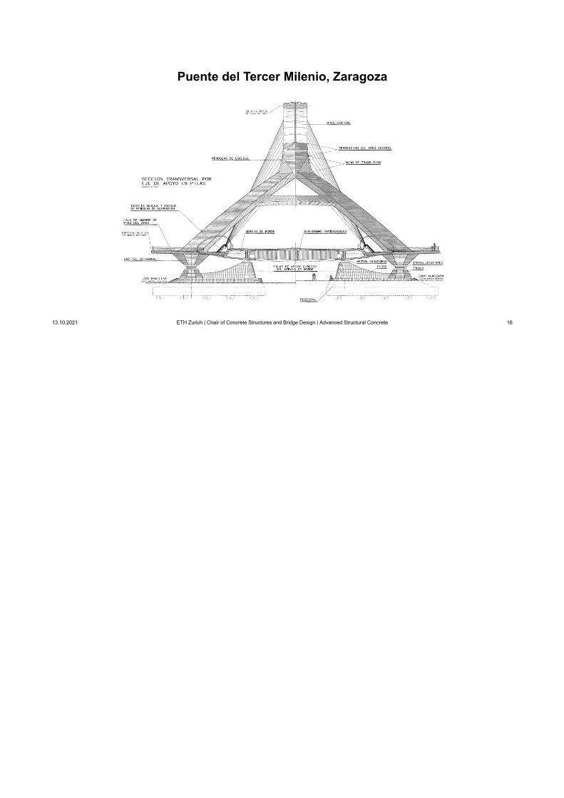
Puente del Tercer Milenio, Zaragoza

The application of prestressing to membrane, slab and shell structures is illustrated using the tying slabs(«lajas de amarre») of the Puente del Tercer Milenio in Zaragoza.
This bridge was designed (detailed design for tender) in 2002. (conceptual design by Prof. Juan JoséArenas, W. Kaufmann as project manager).
It was built only some years later, for the Expo 2008.
Puente del Tercer Milenio, Zaragoza
13.10.2021 ETH Zurich | Chair of Concrete Structures and Bridge Design | Advanced Structural Concrete 12
Project / Photos: Arenas & Asociados / Juan José Arenas de Pablo
Puente del Tercer Milenio, Zaragoza
13.10.2021 ETH Zurich | Chair of Concrete Structures and Bridge Design | Advanced Structural Concrete 12
Project / Photos: Arenas & Asociados / Juan José Arenas de Pablo
Puente del Tercer Milenio, Zaragoza
13.10.2021 ETH Zurich | Chair of Concrete Structures and Bridge Design | Advanced Structural Concrete 12
Project / Photos: Arenas & Asociados / Juan José Arenas de Pablo

It is a very wide bridge, carrying 6+2 traffic lanes plus separate sidewalks with wind barriers on each side.
Among other technical challenges, the design of the tying slabs (equilibrating the huge horizontal thrust ofthe arch, but also acting as slabs under traffic load) was a demanding task. They were heavily prestressedand dimensioned using the sandwich model (partly modified to carry compression in the core), treating theprestressing as load (anchor and deviation forces).
Puente del Tercer Milenio, Zaragoza
13.10.2021 ETH Zurich | Chair of Concrete Structures and Bridge Design | Advanced Structural Concrete 13
Self compacting white concreteArch: C75/90Deck: C60/70
Puente del Tercer Milenio, Zaragoza
13.10.2021 ETH Zurich | Chair of Concrete Structures and Bridge Design | Advanced Structural Concrete 13
Self compacting white concreteArch: C75/90Deck: C60/70
Puente del Tercer Milenio, Zaragoza
13.10.2021 ETH Zurich | Chair of Concrete Structures and Bridge Design | Advanced Structural Concrete 13
Self compacting white concreteArch: C75/90Deck: C60/70

Puente del Tercer Milenio, Zaragoza
13.10.2021 ETH Zurich | Chair of Concrete Structures and Bridge Design | Advanced Structural Concrete 14
27 m
35 m
216 m
43 m
68 m
27 m
Puente del Tercer Milenio, Zaragoza
13.10.2021 ETH Zurich | Chair of Concrete Structures and Bridge Design | Advanced Structural Concrete 14
27 m
35 m
216 m
43 m
68 m
27 m
Puente del Tercer Milenio, Zaragoza
13.10.2021 ETH Zurich | Chair of Concrete Structures and Bridge Design | Advanced Structural Concrete 14
27 m
35 m
216 m
43 m
68 m
27 m

15
Puente del Tercer Milenio, Zaragoza
13.10.2021 ETH Zurich | Chair of Concrete Structures and Bridge Design | Advanced Structural Concrete 15
3
4 4
1 12 2
44
10
11
6
7 7
11
3
44
5 5
11
9 9
2 2
7 7
7 7
11
6
6
8
2 27 7
Puente del Tercer Milenio, Zaragoza
13.10.2021 ETH Zurich | Chair of Concrete Structures and Bridge Design | Advanced Structural Concrete 15
3
4 4
1 12 2
44
10
11
6
7 7
11
3
44
5 5
11
9 9
2 2
7 7
7 7
11
6
6
8
2 27 7
Puente del Tercer Milenio, Zaragoza
13.10.2021 ETH Zurich | Chair of Concrete Structures and Bridge Design | Advanced Structural Concrete 15
3
4 4
1 12 2
44
10
11
6
7 7
11
3
44
5 5
11
9 9
2 2
7 7
7 7
11
6
6
8
2 27 7
Puente del Tercer Milenio, Zaragoza
13.10.2021 ETH Zurich | Chair of Concrete Structures and Bridge Design | Advanced Structural Concrete 16
Puente del Tercer Milenio, Zaragoza
13.10.2021 ETH Zurich | Chair of Concrete Structures and Bridge Design | Advanced Structural Concrete 16
Puente del Tercer Milenio, Zaragoza
13.10.2021 ETH Zurich | Chair of Concrete Structures and Bridge Design | Advanced Structural Concrete 16

Puente del Tercer Milenio, Zaragoza
13.10.2021 ETH Zurich | Chair of Concrete Structures and Bridge Design | Advanced Structural Concrete 17
Puente del Tercer Milenio, Zaragoza
13.10.2021 ETH Zurich | Chair of Concrete Structures and Bridge Design | Advanced Structural Concrete 17
Puente del Tercer Milenio, Zaragoza
13.10.2021 ETH Zurich | Chair of Concrete Structures and Bridge Design | Advanced Structural Concrete 17

Puente del Tercer Milenio, Zaragoza
13.10.2021 ETH Zurich | Chair of Concrete Structures and Bridge Design | Advanced Structural Concrete 18
Puente del Tercer Milenio, Zaragoza
13.10.2021 ETH Zurich | Chair of Concrete Structures and Bridge Design | Advanced Structural Concrete 18
Puente del Tercer Milenio, Zaragoza
13.10.2021 ETH Zurich | Chair of Concrete Structures and Bridge Design | Advanced Structural Concrete 18

Puente del Tercer Milenio, Zaragoza
13.10.2021 ETH Zurich | Chair of Concrete Structures and Bridge Design | Advanced Structural Concrete 19
Puente del Tercer Milenio, Zaragoza
13.10.2021 ETH Zurich | Chair of Concrete Structures and Bridge Design | Advanced Structural Concrete 19
Puente del Tercer Milenio, Zaragoza
13.10.2021 ETH Zurich | Chair of Concrete Structures and Bridge Design | Advanced Structural Concrete 19

13.10.2021 ETH Zurich | Chair of Concrete Structures and Bridge Design | Advanced Structural Concrete 20
2 In plane loading –walls and beams
2.2 Stress fields with prestressing
In-class exercise
13.10.2021 ETH Zurich | Chair of Concrete Structures and Bridge Design | Advanced Structural Concrete 20
2 In plane loading –walls and beams
2.2 Stress fields with prestressing
In-class exercise
13.10.2021 ETH Zurich | Chair of Concrete Structures and Bridge Design | Advanced Structural Concrete 20
2 In plane loading –walls and beams
2.2 Stress fields with prestressing
In-class exercise

27 m
35 m
216 m
43 m
68 m
27 m
In-class exercise
1) Determine the global force flow and the magnitude of the forces.
Note that the supports at the arch abutments directly resist the verticalcomponent of the arch force, but are free to move horizontally( full horizontal arch thrust carried by the bridge deck)
2) Determine the in-plane force flow in the tying slabs in more detail, using astrut-and-tie model.
3) Determine the amount of prestressing needed and pre-dimension the tyingslabs for membrane elements.
Materials:
Concrete: C60/70
Steel: B500B
Prestressing steel: Y1860
13.10.2021 ETH Zurich | Chair of Concrete Structures and Bridge Design | Advanced Structural Concrete 21
230MN
140MN
140MN
A
27 m
35 m
216 m
43 m
68 m
27 m
In-class exercise
1) Determine the global force flow and the magnitude of the forces.
Note that the supports at the arch abutments directly resist the verticalcomponent of the arch force, but are free to move horizontally( full horizontal arch thrust carried by the bridge deck)
2) Determine the in-plane force flow in the tying slabs in more detail, using astrut-and-tie model.
3) Determine the amount of prestressing needed and pre-dimension the tyingslabs for membrane elements.
Materials:
Concrete: C60/70
Steel: B500B
Prestressing steel: Y1860
13.10.2021 ETH Zurich | Chair of Concrete Structures and Bridge Design | Advanced Structural Concrete 21
230MN
140MN
140MN
A
13.10.2021 ETH Zurich | Chair of Concrete Structures and Bridge Design | Advanced Structural Concrete 23
2 In plane loading –walls and beams
2.2 Stress fields with prestressing
Exercise solution
13.10.2021 ETH Zurich | Chair of Concrete Structures and Bridge Design | Advanced Structural Concrete 23
2 In plane loading –walls and beams
2.2 Stress fields with prestressing
Exercise solution
13.10.2021 ETH Zurich | Chair of Concrete Structures and Bridge Design | Advanced Structural Concrete 23
2 In plane loading –walls and beams
2.2 Stress fields with prestressing
Exercise solution

Exercise - Solution
13.10.2021 ETH Zurich | Chair of Concrete Structures and Bridge Design | Advanced Structural Concrete 24
Z2Z2
Z2Z2
Z1 Z1
R
Z2
R
Z2
Z3 Z3
Z4
Z4
Z4
Z4
Z2
Z2
Z2
Z2
Z5
Z5
Z5
Z5
Z1 Z1Z3
Z3
Z3
Z3
Z3
Z3
Z3
Z3
Z2 Z2
Z4 Z4
Z3
Z3
Z3
Z3
Z3
Z3
Z3
Z3
Figura 5.4.4. Comportamiento estructural del puente.

Exercise - Solution
13.10.2021 ETH Zurich | Chair of Concrete Structures and Bridge Design | Advanced Structural Concrete 25
30°
35°
14070
121
121
121
70
100100
Exercise - Solution
13.10.2021 ETH Zurich | Chair of Concrete Structures and Bridge Design | Advanced Structural Concrete 25
30°
35°
14070
121
121
121
70
100100
Exercise - Solution
13.10.2021 ETH Zurich | Chair of Concrete Structures and Bridge Design | Advanced Structural Concrete 25
30°
35°
14070
121
121
121
70
100100

Exercise - Solution
13.10.2021 ETH Zurich | Chair of Concrete Structures and Bridge Design | Advanced Structural Concrete 26
23m
15.3m10
m
30°
121
61
70
61
3535
5050
30
Exercise - Solution
13.10.2021 ETH Zurich | Chair of Concrete Structures and Bridge Design | Advanced Structural Concrete 26
23m
15.3m10
m
30°
121
61
70
61
3535
5050
30
Exercise - Solution
13.10.2021 ETH Zurich | Chair of Concrete Structures and Bridge Design | Advanced Structural Concrete 26
23m
15.3m10
m
30°
121
61
70
61
3535
5050
30

Exercise - Solution
13.10.2021 ETH Zurich | Chair of Concrete Structures and Bridge Design | Advanced Structural Concrete 27
23m
15.3m10
m
30°
P1,∞
P1,∞
P1,∞
P3,∞ P3,∞
P4,∞
P4,∞
P1,∞
P2,∞
P2,∞
Exercise - Solution
13.10.2021 ETH Zurich | Chair of Concrete Structures and Bridge Design | Advanced Structural Concrete 27
23m
15.3m10
m
30°
P1,∞
P1,∞
P1,∞
P3,∞ P3,∞
P4,∞
P4,∞
P1,∞
P2,∞
P2,∞
Exercise - Solution
13.10.2021 ETH Zurich | Chair of Concrete Structures and Bridge Design | Advanced Structural Concrete 27
23m
15.3m10
m
30°
P1,∞
P1,∞
P1,∞
P3,∞ P3,∞
P4,∞
P4,∞
P1,∞
P2,∞
P2,∞

23m
15.3m10
m
30°
P1,∞
P1,∞
P1,∞
P3,∞ P3,∞
P4,∞
P4,∞
P1,∞
P2,∞
P2,∞
Exercise - Solution
13.10.2021 ETH Zurich | Chair of Concrete Structures and Bridge Design | Advanced Structural Concrete 28
2,
1, 1,2
,
2
1, 1,
1,0
1,0, ,0
2,
A 150mm
2 0.7 0.85 121MN
109334mm
Choice: 40x19 0.6''
114000mm2 126.2MN
2 148.4MN2
18.6 MPa 0.8 10m 0.8m
:
ok
ok
p i
ppk d
p erf
p
d
c p cd
P f A F
A
AP F
PP
f
P
3,
4,
Choice: 10x19 0.6'': Choice: 22x19 0.6'': Choice: 31x19 0.6''
22PP 23m
15.3m10
m
30°
P1,∞
P1,∞
P1,∞
P3,∞ P3,∞
P4,∞
P4,∞
P1,∞
P2,∞
P2,∞
Exercise - Solution
13.10.2021 ETH Zurich | Chair of Concrete Structures and Bridge Design | Advanced Structural Concrete 28
2,
1, 1,2
,
2
1, 1,
1,0
1,0, ,0
2,
A 150mm
2 0.7 0.85 121MN
109334mm
Choice: 40x19 0.6''
114000mm2 126.2MN
2 148.4MN2
18.6 MPa 0.8 10m 0.8m
:
ok
ok
p i
ppk d
p erf
p
d
c p cd
P f A F
A
AP F
PP
f
P
3,
4,
Choice: 10x19 0.6'': Choice: 22x19 0.6'': Choice: 31x19 0.6''
22PP

Exercise - Solution
13.10.2021 ETH Zurich | Chair of Concrete Structures and Bridge Design | Advanced Structural Concrete 29
Exercise - Solution
13.10.2021 ETH Zurich | Chair of Concrete Structures and Bridge Design | Advanced Structural Concrete 29
Exercise - Solution
13.10.2021 ETH Zurich | Chair of Concrete Structures and Bridge Design | Advanced Structural Concrete 29

Exercise - Solution
13.10.2021 ETH Zurich | Chair of Concrete Structures and Bridge Design | Advanced Structural Concrete 30
Exercise - Solution
13.10.2021 ETH Zurich | Chair of Concrete Structures and Bridge Design | Advanced Structural Concrete 30
Exercise - Solution
13.10.2021 ETH Zurich | Chair of Concrete Structures and Bridge Design | Advanced Structural Concrete 30

13.10.2021 ETH Zurich | Chair of Concrete Structures and Bridge Design | Advanced Structural Concrete 31
2 In plane loading –walls and beams
2.2 Stress fields with prestressing
Construction images
13.10.2021 ETH Zurich | Chair of Concrete Structures and Bridge Design | Advanced Structural Concrete 31
2 In plane loading –walls and beams
2.2 Stress fields with prestressing
Construction images
13.10.2021 ETH Zurich | Chair of Concrete Structures and Bridge Design | Advanced Structural Concrete 31
2 In plane loading –walls and beams
2.2 Stress fields with prestressing
Construction images

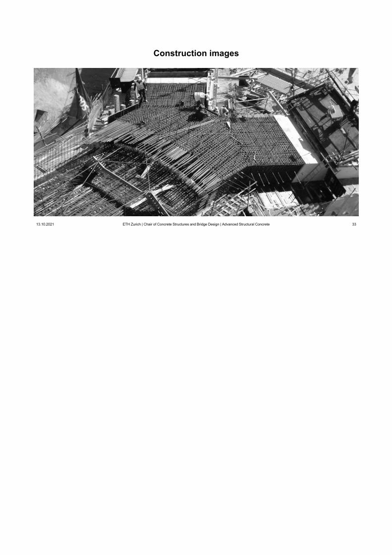
Construction images
13.10.2021 ETH Zurich | Chair of Concrete Structures and Bridge Design | Advanced Structural Concrete 32
Construction images
13.10.2021 ETH Zurich | Chair of Concrete Structures and Bridge Design | Advanced Structural Concrete 32
Construction images
13.10.2021 ETH Zurich | Chair of Concrete Structures and Bridge Design | Advanced Structural Concrete 32
Construction images
13.10.2021 ETH Zurich | Chair of Concrete Structures and Bridge Design | Advanced Structural Concrete 33
Construction images
13.10.2021 ETH Zurich | Chair of Concrete Structures and Bridge Design | Advanced Structural Concrete 33
Construction images
13.10.2021 ETH Zurich | Chair of Concrete Structures and Bridge Design | Advanced Structural Concrete 33

Construction images
13.10.2021 ETH Zurich | Chair of Concrete Structures and Bridge Design | Advanced Structural Concrete 34
1 2 3
Construction images
13.10.2021 ETH Zurich | Chair of Concrete Structures and Bridge Design | Advanced Structural Concrete 34
1 2 3
Construction images
13.10.2021 ETH Zurich | Chair of Concrete Structures and Bridge Design | Advanced Structural Concrete 34
1 2 3

Construction images
13.10.2021 ETH Zurich | Chair of Concrete Structures and Bridge Design | Advanced Structural Concrete 35
Construction images
13.10.2021 ETH Zurich | Chair of Concrete Structures and Bridge Design | Advanced Structural Concrete 35
Construction images
13.10.2021 ETH Zurich | Chair of Concrete Structures and Bridge Design | Advanced Structural Concrete 35

Construction images
13.10.2021 ETH Zurich | Chair of Concrete Structures and Bridge Design | Advanced Structural Concrete 36
1
Construction images
13.10.2021 ETH Zurich | Chair of Concrete Structures and Bridge Design | Advanced Structural Concrete 36
1
Construction images
13.10.2021 ETH Zurich | Chair of Concrete Structures and Bridge Design | Advanced Structural Concrete 36
1

Construction images
13.10.2021 ETH Zurich | Chair of Concrete Structures and Bridge Design | Advanced Structural Concrete 37
120 MN
Construction images
13.10.2021 ETH Zurich | Chair of Concrete Structures and Bridge Design | Advanced Structural Concrete 37
120 MN
Construction images
13.10.2021 ETH Zurich | Chair of Concrete Structures and Bridge Design | Advanced Structural Concrete 37
120 MN

(six 2000-t hydraulic jacks used to demould arch and deck (700 bar, Ø60 cm -> 20 MN/jack, adjusting ring continuously tracked)
Construction images
13.10.2021 ETH Zurich | Chair of Concrete Structures and Bridge Design | Advanced Structural Concrete 38
Construction images
13.10.2021 ETH Zurich | Chair of Concrete Structures and Bridge Design | Advanced Structural Concrete 38
Construction images
13.10.2021 ETH Zurich | Chair of Concrete Structures and Bridge Design | Advanced Structural Concrete 38

Construction images
13.10.2021 ETH Zurich | Chair of Concrete Structures and Bridge Design | Advanced Structural Concrete 39
Construction images
13.10.2021 ETH Zurich | Chair of Concrete Structures and Bridge Design | Advanced Structural Concrete 39
Construction images
13.10.2021 ETH Zurich | Chair of Concrete Structures and Bridge Design | Advanced Structural Concrete 39

Construction images
13.10.2021 ETH Zurich | Chair of Concrete Structures and Bridge Design | Advanced Structural Concrete 40
19
Construction images
13.10.2021 ETH Zurich | Chair of Concrete Structures and Bridge Design | Advanced Structural Concrete 40
19
Construction images
13.10.2021 ETH Zurich | Chair of Concrete Structures and Bridge Design | Advanced Structural Concrete 40
19