Embed Size (px)
Citation preview
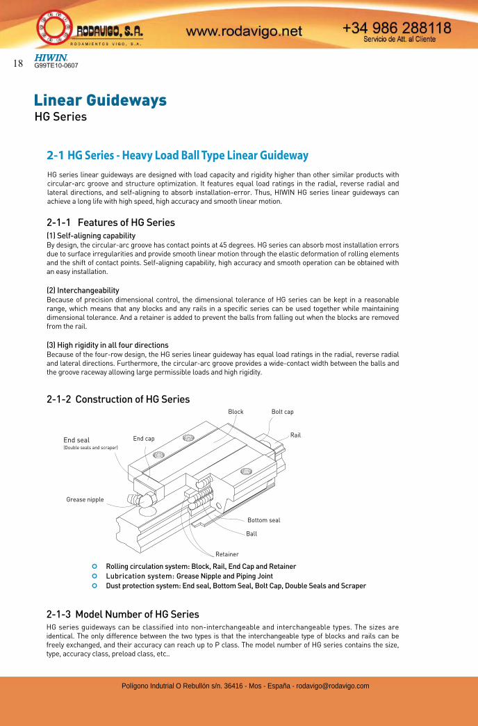
2. HIWIN Linear Guideway Product Series
Hiwin has developed numerous products to satisfy various needs of customers. HG series is a heavy load ball-type guideway for machine tools which requires high accuracy and rigidity; the EG series is a low-profile guideway for the automation industry which requires high speed and smooth motion; and the MG Series is a miniature type for semiconductor equipment and other miniature equipment.
(1) Types & series
Table 2.2 Accuracy Classes
(3) Classification of preload
(2) Accuracy classes
Series
Assembly Type Interchangeable Type
Normal High PrecisionSuper
Precision
Ultra
PrecisionNormal High Precision
(C) (H) (P) (SP) (UP) (C) (H) (P)
HG
EG
MGN - -
MGW - - - - -
SeriesAssembly
HeightLoad
Square
Tap hole
Flange
Tap hole Drilled hole Combination
HG
HighHeavy Load HGH-CA - - -
Super Heavy Load
HGH-HA - - -
LowHeavy Load - HGW-CA HGW-CB HGW-CC
Super Heavy Load
- HGW-HA HGW-HB HGW-HC
EG LowMedium Load EGH-SA EGW-SA EGW-SB -
Heavy Load EGH-CA EGW-CA EGW-CB -
MGN -Standard MGN-C - - -
Long MGN-H - - -
MGW -Standard MGW-C - - -
Long MGW-H - - -
Series
Non-interchangeable Type Interchangeable Type
Light preload Medium Preload Heavy Preload Light Preload Medium Preload
(Z0) (ZA) (ZB) (Z0) (ZA)
HG
EG
Series
Non-interchangeable Type Interchangeable Type
Light
Clearance
Very Ligh
Preload
Light
Preload
Medium
Preload
Heavy
Preload
Light
Clearance
Very Ligh
Preload
Light
Preload
(ZF) (Z0) (Z1) (Z2) (Z3) (ZF) (Z0) (Z1)
MGN - -
MGW - - - - -
Table 2.3 Preload
Table 2.1 Types & Series
G99TE10-0607 17
Polígono Indutrial O Rebullón s/n. 36416 - Mos - España - [email protected]
Linear GuidewaysHG Series
¢ Rolling circulation system: Block, Rail, End Cap and Retainer
¢ Lubrication system: Grease Nipple and Piping Joint
¢ Dust protection system: End seal, Bottom Seal, Bolt Cap, Double Seals and Scraper
2-1 HG Series - Heavy Load Ball Type Linear Guideway
2-1-3 Model Number of HG SeriesHG series guideways can be classified into non-interchangeable and interchangeable types. The sizes are identical. The only difference between the two types is that the interchangeable type of blocks and rails can be freely exchanged, and their accuracy can reach up to P class. The model number of HG series contains the size, type, accuracy class, preload class, etc..
2-1-1 Features of HG Series (1) Self-aligning capability By design, the circular-arc groove has contact points at 45 degrees. HG series can absorb most installation errors due to surface irregularities and provide smooth linear motion through the elastic deformation of rolling elements and the shift of contact points. Self-aligning capability, high accuracy and smooth operation can be obtained with an easy installation.
(2) Interchangeability Because of precision dimensional control, the dimensional tolerance of HG series can be kept in a reasonable range, which means that any blocks and any rails in a specific series can be used together while maintaining dimensional tolerance. And a retainer is added to prevent the balls from falling out when the blocks are removed from the rail.
(3) High rigidity in all four directions Because of the four-row design, the HG series linear guideway has equal load ratings in the radial, reverse radial and lateral directions. Furthermore, the circular-arc groove provides a wide-contact width between the balls and the groove raceway allowing large permissible loads and high rigidity.
Block
End seal(Double seals and scraper)
Grease nipple
End capRail
Bolt cap
Retainer
Bottom seal
Ball
HG series linear guideways are designed with load capacity and rigidity higher than other similar products with circular-arc groove and structure optimization. It features equal load ratings in the radial, reverse radial and lateral directions, and self-aligning to absorb installation-error. Thus, HIWIN HG series linear guideways can achieve a long life with high speed, high accuracy and smooth linear motion.
2-1-2 Construction of HG Series
G99TE10-060718
Polígono Indutrial O Rebullón s/n. 36416 - Mos - España - [email protected]
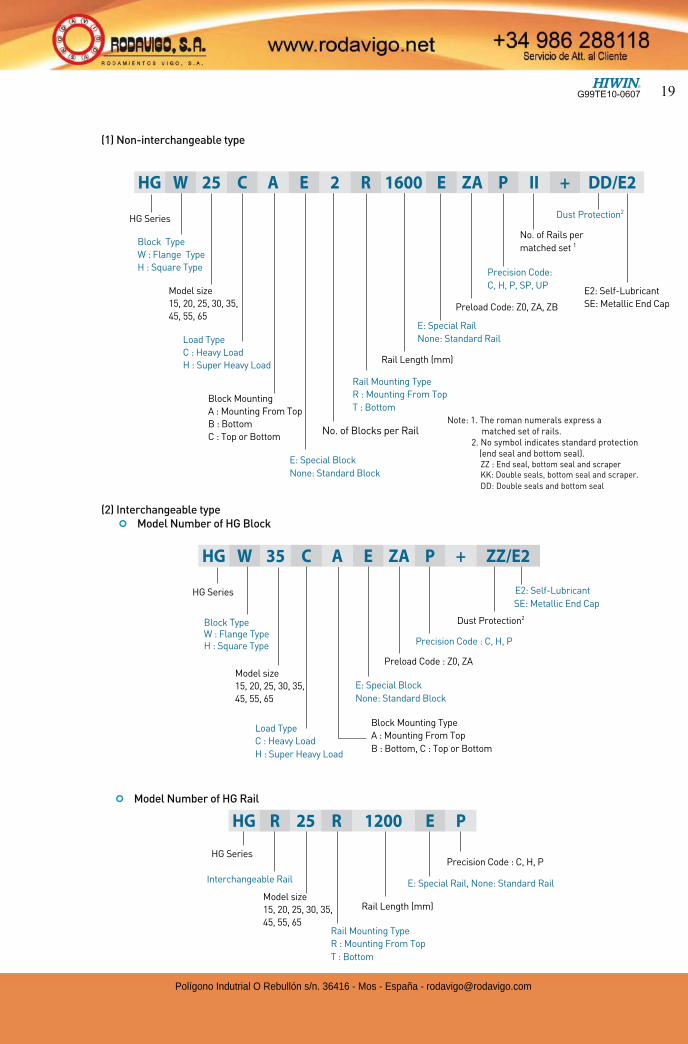
(1) Non-interchangeable type
(2) Interchangeable type ¢ Model Number of HG Block
¢ Model Number of HG Rail
HG Series
Block Type W : Flange Type H : Square Type
Block Mounting Type
A : Mounting From Top
B : Bottom, C : Top or Bottom
E: Special Block
None: Standard Block
Dust Protection2
Precision Code : C, H, P
Preload Code : Z0, ZA
HG Series
Rail Mounting Type
R : Mounting From Top
T : Bottom
Rail Length (mm)
E: Special Rail, None: Standard Rail
Precision Code : C, H, P
Interchangeable Rail
Note: 1. The roman numerals express a matched set of rails.
2. No symbol indicates standard protection (end seal and bottom seal).ZZ : End seal, bottom seal and scraperKK: Double seals, bottom seal and scraper.
DD: Double seals and bottom seal
HG Series
Block Type
W : Flange Type
H : Square Type
Model size
15, 20, 25, 30, 35,
45, 55, 65
E: Special Block
None: Standard Block
Rail Length (mm)
E: Special Rail
None: Standard Rail
Rail Mounting Type
R : Mounting From Top
T : Bottom
Preload Code: Z0, ZA, ZB
Precision Code:
C, H, P, SP, UP
No. of Rails per
matched set 1
Dust Protection2
E2: Self-Lubricant
SE: Metallic End Cap
E2: Self-Lubricant
SE: Metallic End Cap
HG W 25 C A E 2 R 1600 E ZA P II + DD/E2
Load Type
C : Heavy Load
H : Super Heavy Load
Block Mounting
A : Mounting From Top
B : Bottom
C : Top or Bottom
Model size
15, 20, 25, 30, 35,
45, 55, 65
Load Type
C : Heavy Load
H : Super Heavy Load
HG W 35 C A E ZA P + ZZ/E2
Model size
15, 20, 25, 30, 35,
45, 55, 65
HG R 25 R 1200 E P
No. of Blocks per Rail
G99TE10-0607 19
Polígono Indutrial O Rebullón s/n. 36416 - Mos - España - [email protected]
Linear GuidewaysHG Series
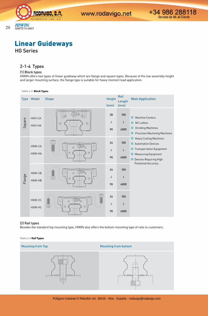
Table 2.5 Rail Types
Table 2.4 Block Types
2-1-4 Types(1) Block typesHIWIN offers two types of linear guideway which are flange and square types. Because of the low assembly height and larger mounting surface, the flange type is suitable for heavy moment load application.
Type Model Shape HeightRail
LengthMain Application
(mm) (mm)
HGH-CA
HGH-HA
28
i
90
100
i
4000
¢ Machine Centers
¢ NC Lathes
¢ Grinding Machines
¢ Precision Machining Machines
¢ Heavy Cutting Machines
¢ Automation Devices
¢ Transportation Equipment
¢ Measuring Equipment
¢ Devices Requiring High
Positional Accuracy
HGW-CA
HGW-HA
24
i
90
100
i
4000
HGW-CB
HGW-HB
24
i
90
100
i
4000
HGW-CC
HGW-HC
24
i
90
100
i
4000
Sq
uar
e F
lan
ge
Mounting from Top Mounting from bottom
(2) Rail typesBesides the standard top mounting type, HIWIN also offers the bottom mounting type of rails to customers.
G99TE10-060720
Polígono Indutrial O Rebullón s/n. 36416 - Mos - España - [email protected]
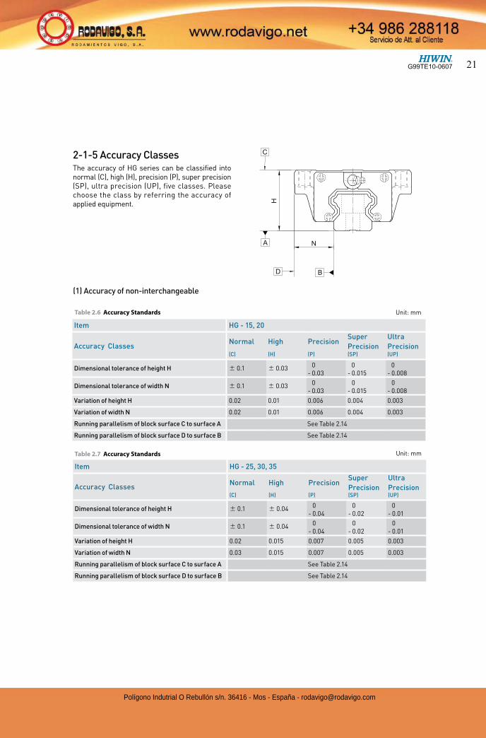
2-1-5 Accuracy ClassesThe accuracy of HG series can be classified into normal (C), high (H), precision (P), super precision (SP), ultra precision (UP), five classes. Please choose the class by referring the accuracy of applied equipment.
Table 2.6 Accuracy Standards Unit: mm
(1) Accuracy of non-interchangeable
Item HG - 25, 30, 35
Accuracy ClassesNormal High Precision
Super
Precision
Ultra
Precision (C) (H) (P) (SP) (UP)
Dimensional tolerance of height H 0.1 0.04 0- 0.04
0- 0.02
0- 0.01
Dimensional tolerance of width N 0.1 0.04 0- 0.04
0- 0.02
0- 0.01
Variation of height H 0.02 0.015 0.007 0.005 0.003
Variation of width N 0.03 0.015 0.007 0.005 0.003
Running parallelism of block surface C to surface A See Table 2.14
Running parallelism of block surface D to surface B See Table 2.14
Item HG - 15, 20
Accuracy ClassesNormal High Precision
Super
Precision
Ultra
Precision (C) (H) (P) (SP) (UP)
Dimensional tolerance of height H 0.1 0.03 0- 0.03
0- 0.015
0- 0.008
Dimensional tolerance of width N 0.1 0.03 0- 0.03
0- 0.015
0- 0.008
Variation of height H 0.02 0.01 0.006 0.004 0.003
Variation of width N 0.02 0.01 0.006 0.004 0.003
Running parallelism of block surface C to surface A See Table 2.14
Running parallelism of block surface D to surface B See Table 2.14
Table 2.7 Accuracy Standards Unit: mm
G99TE10-0607 21
Polígono Indutrial O Rebullón s/n. 36416 - Mos - España - [email protected]
Linear GuidewaysHG Series
Table 2.10 Accuracy Standards
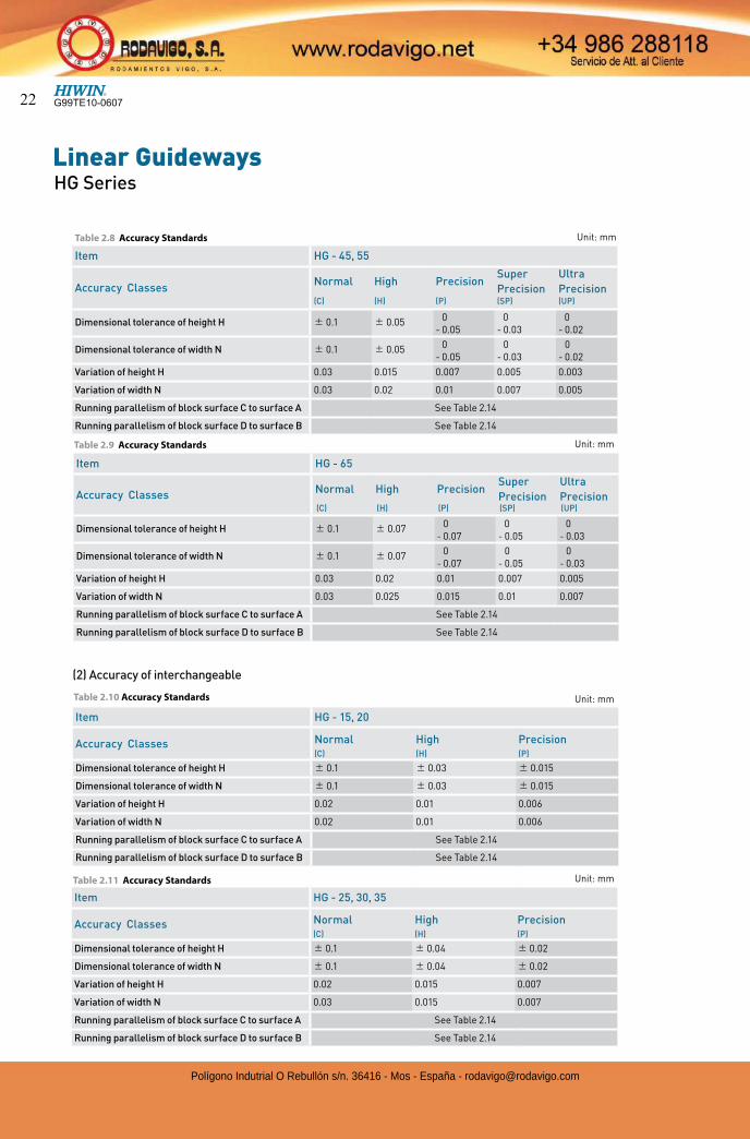
(2) Accuracy of interchangeable
Item HG - 65
Accuracy ClassesNormal High Precision
Super
Precision
Ultra
Precision (C) (H) (P) (SP) (UP)
Dimensional tolerance of height H 0.1 0.07 0- 0.07
0- 0.05
0- 0.03
Dimensional tolerance of width N 0.1 0.07 0- 0.07
0- 0.05
0- 0.03
Variation of height H 0.03 0.02 0.01 0.007 0.005
Variation of width N 0.03 0.025 0.015 0.01 0.007
Running parallelism of block surface C to surface A See Table 2.14
Running parallelism of block surface D to surface B See Table 2.14
Item HG - 45, 55
Accuracy ClassesNormal High Precision
Super
Precision
Ultra
Precision (C) (H) (P) (SP) (UP)
Dimensional tolerance of height H 0.1 0.05 0- 0.05
0- 0.03
0- 0.02
Dimensional tolerance of width N 0.1 0.05 0- 0.05
0- 0.03
0- 0.02
Variation of height H 0.03 0.015 0.007 0.005 0.003
Variation of width N 0.03 0.02 0.01 0.007 0.005
Running parallelism of block surface C to surface A See Table 2.14
Running parallelism of block surface D to surface B See Table 2.14
Unit: mm
Item HG - 15, 20
Accuracy Classes Normal High Precision(C) (H) (P)
Dimensional tolerance of height H 0.1 0.03 0.015
Dimensional tolerance of width N 0.1 0.03 0.015
Variation of height H 0.02 0.01 0.006
Variation of width N 0.02 0.01 0.006
Running parallelism of block surface C to surface A See Table 2.14
Running parallelism of block surface D to surface B See Table 2.14
Item HG - 25, 30, 35
Accuracy Classes Normal High Precision(C) (H) (P)
Dimensional tolerance of height H 0.1 0.04 0.02
Dimensional tolerance of width N 0.1 0.04 0.02
Variation of height H 0.02 0.015 0.007
Variation of width N 0.03 0.015 0.007
Running parallelism of block surface C to surface A See Table 2.14
Running parallelism of block surface D to surface B See Table 2.14
Table 2.8 Accuracy Standards Unit: mm
Table 2.9 Accuracy Standards Unit: mm
Table 2.11 Accuracy Standards Unit: mm
G99TE10-060722
Polígono Indutrial O Rebullón s/n. 36416 - Mos - España - [email protected]
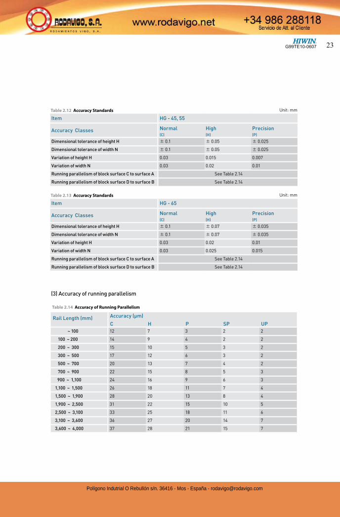
(3) Accuracy of running parallelism
Rail Length (mm) Accuracy (µm)
C H P SP UP
~ 100 12 7 3 2 2
100 ~ 200 14 9 4 2 2
200 ~ 300 15 10 5 3 2
300 ~ 500 17 12 6 3 2
500 ~ 700 20 13 7 4 2
700 ~ 900 22 15 8 5 3
900 ~ 1,100 24 16 9 6 3
1,100 ~ 1,500 26 18 11 7 4
1,500 ~ 1,900 28 20 13 8 4
1,900 ~ 2,500 31 22 15 10 5
2,500 ~ 3,100 33 25 18 11 6
3,100 ~ 3,600 36 27 20 14 7
3,600 ~ 4,000 37 28 21 15 7
Item HG - 45, 55
Accuracy Classes Normal High Precision(C) (H) (P)
Dimensional tolerance of height H 0.1 0.05 0.025
Dimensional tolerance of width N 0.1 0.05 0.025
Variation of height H 0.03 0.015 0.007
Variation of width N 0.03 0.02 0.01
Running parallelism of block surface C to surface A See Table 2.14
Running parallelism of block surface D to surface B See Table 2.14
Table 2.12 Accuracy Standards Unit: mm
Item HG - 65
Accuracy Classes Normal High Precision(C) (H) (P)
Dimensional tolerance of height H 0.1 0.07 0.035
Dimensional tolerance of width N 0.1 0.07 0.035
Variation of height H 0.03 0.02 0.01
Variation of width N 0.03 0.025 0.015
Running parallelism of block surface C to surface A See Table 2.14
Running parallelism of block surface D to surface B See Table 2.14
Table 2.13 Accuracy Standards Unit: mm
Table 2.14 Accuracy of Running Parallelism
G99TE10-0607 23
Polígono Indutrial O Rebullón s/n. 36416 - Mos - España - [email protected]
Linear GuidewaysHG Series
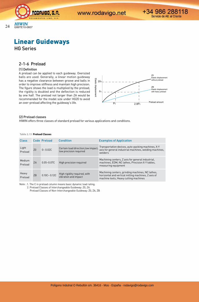
(2) Preload classesHIWIN offers three classes of standard preload for various applications and conditions.
Note : 1. The C in preload column means basic dynamic load rating.2. Preload Classes of Interchangeable Guideway: Z0, ZA.
Preload Classes of Non-Interchangeable Guideway: Z0, ZA, ZB
2-1-6 Preload(1) Definition A preload can be applied to each guideway. Oversized balls are used. Generally, a linear motion guideway has a negative clearance between groove and balls in order to improve stiffness and maintain high precision. The figure shows the load is multiplied by the preload, the rigidity is doubled and the deflection is reduced by one half. The preload not larger than ZA would be recommended for the model size under HG20 to avoid an over-preload affecting the guideway’s life.
Ela
stic
dis
pla
cem
ent
Preload amount
Z0Elastic displacement
without preload
ZBElastic displacement
with heavy preload
Class Code Preload Condition Examples of Application
Light
PreloadZ0 0~ 0.02C
Certain load direction,low impact, low precision required
Transportation devices, auto-packing machines, X-Y axis for general industrial machines, welding machines, welders
Medium
PreloadZA 0.05~0.07C High precision required
Machining centers, Z axis for general industrial, machines, EDM, NC lathes, Precision X-Y tables, measuring equipment
Heavy
PreloadZB 0.10C~ 0.12C
High rigidity required, with vibration and impact
Machining centers, grinding machines, NC lathes, horizontal and vertical milling machines, Z axis of machine tools, Heavy cutting machines
Table 2.15 Preload Classes
G99TE10-060724
Polígono Indutrial O Rebullón s/n. 36416 - Mos - España - [email protected]
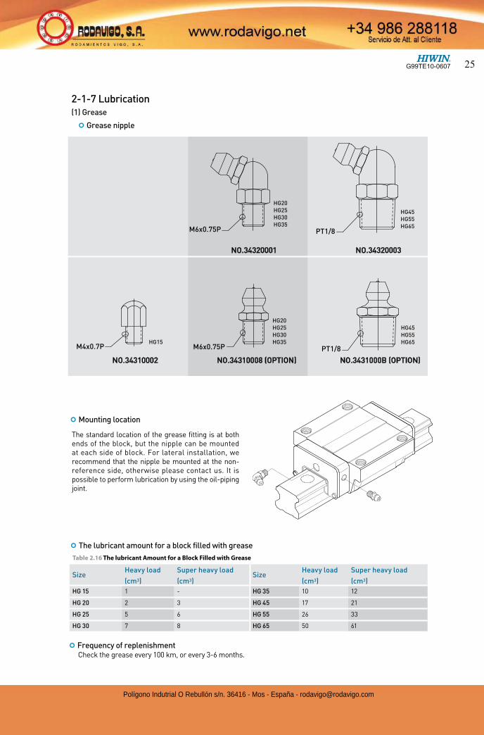
The standard location of the grease fitting is at both ends of the block, but the nipple can be mounted at each side of block. For lateral installation, we recommend that the nipple be mounted at the non-reference side, otherwise please contact us. It is possible to perform lubrication by using the oil-piping joint.
HG15
HG20
HG30HG35
HG25
HG20
HG30HG35
HG25
HG45
HG65HG55
HG45
HG65HG55
M6x0.75P
M6x0.75PM4x0.7P
NO.34310002 NO.34310008 (OPTION) NO.3431000B (OPTION)
NO.34320003 NO.34320001
PT1/8
PT1/8
¢ The lubricant amount for a block filled with grease
Table 2.16 The lubricant Amount for a Block Filled with Grease
2-1-7 Lubrication(1) Grease
¢ Grease nipple
¢ Mounting location
Size Heavy load Super heavy load
SizeHeavy load Super heavy load
(cm3) (cm3) (cm3) (cm3)
HG 15 1 - HG 35 10 12
HG 20 2 3 HG 45 17 21
HG 25 5 6 HG 55 26 33
HG 30 7 8 HG 65 50 61
¢ Frequency of replenishmentCheck the grease every 100 km, or every 3-6 months.
G99TE10-0607 25
Polígono Indutrial O Rebullón s/n. 36416 - Mos - España - [email protected]
Linear GuidewaysHG Series
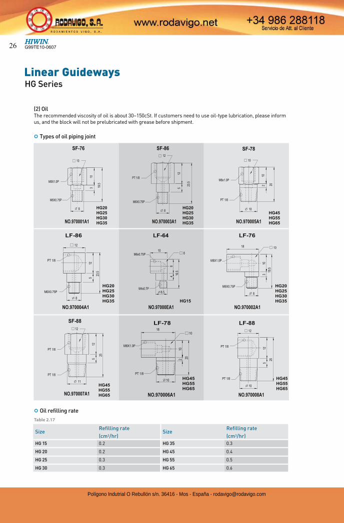
Size Refilling rate
SizeRefilling rate
(cm3/hr) (cm3/hr)
HG 15 0.2 HG 35 0.3
HG 20 0.2 HG 45 0.4
HG 25 0.3 HG 55 0.5
HG 30 0.3 HG 65 0.6
(2) OilThe recommended viscosity of oil is about 30~150cSt. If customers need to use oil-type lubrication, please inform us, and the block will not be prelubricated with grease before shipment.
¢ Types of oil piping joint
¢ Oil refilling rate
Table 2.17
G99TE10-060726
Polígono Indutrial O Rebullón s/n. 36416 - Mos - España - [email protected]
Size Thinkness (t2)
SizeThinkness (t2)
(mm) (mm)
HG 15 SC 1.5 HG 35 SC 1.5
HG 20 SC 1.5 HG 45 SC 1.5
HG 25 SC 1.5 HG 55 SC 1.7
HG 30 SC 1.5 HG 65 SC 1.7
t2
t1
Scraper
End seal
Spacer
End seal
Spacer
Bottom Seal End seal
End seal
Scraper
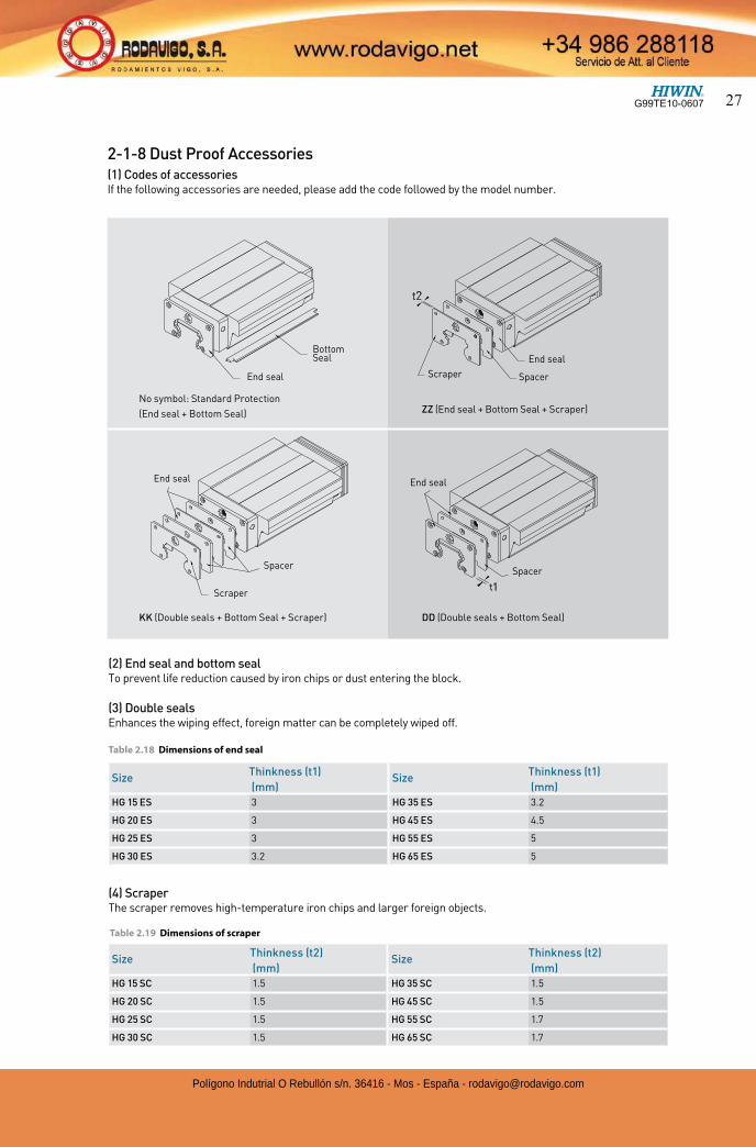
2-1-8 Dust Proof Accessories(1) Codes of accessoriesIf the following accessories are needed, please add the code followed by the model number.
(2) End seal and bottom seal To prevent life reduction caused by iron chips or dust entering the block.
(3) Double sealsEnhances the wiping effect, foreign matter can be completely wiped off.
No symbol: Standard Protection
(End seal + Bottom Seal)
KK (Double seals + Bottom Seal + Scraper) DD (Double seals + Bottom Seal)
ZZ (End seal + Bottom Seal + Scraper)
Spacer
Size Thinkness (t1)
SizeThinkness (t1)
(mm) (mm)
HG 15 ES 3 HG 35 ES 3.2
HG 20 ES 3 HG 45 ES 4.5
HG 25 ES 3 HG 55 ES 5
HG 30 ES 3.2 HG 65 ES 5
Table 2.19 Dimensions of scraper
(4) ScraperThe scraper removes high-temperature iron chips and larger foreign objects.
Table 2.18 Dimensions of end seal
G99TE10-0607 27
Polígono Indutrial O Rebullón s/n. 36416 - Mos - España - [email protected]
Linear GuidewaysHG Series
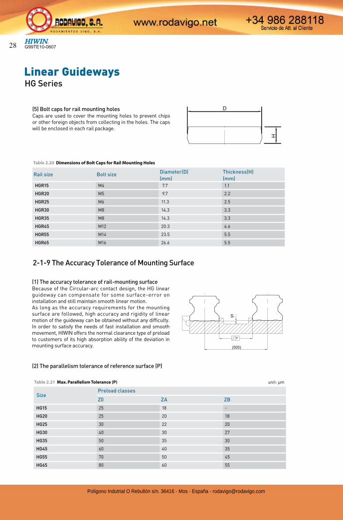
Table 2.20 Dimensions of Bolt Caps for Rail Mounting Holes
(5) Bolt caps for rail mounting holesCaps are used to cover the mounting holes to prevent chips or other foreign objects from collecting in the holes. The caps will be enclosed in each rail package.
2-1-9 The Accuracy Tolerance of Mounting Surface
Rail size Bolt size Diameter(D) Thickness(H)
(mm) (mm)
HGR15 M4 7.7 1.1
HGR20 M5 9.7 2.2
HGR25 M6 11.3 2.5
HGR30 M8 14.3 3.3
HGR35 M8 14.3 3.3
HGR45 M12 20.3 4.6
HGR55 M14 23.5 5.5
HGR65 M16 26.6 5.5
(1) The accuracy tolerance of rail-mounting surfaceBecause of the Circular-arc contact design, the HG linear guideway can compensate for some surface-error on installation and still maintain smooth linear motion.As long as the accuracy requirements for the mounting surface are followed, high accuracy and rigidity of linear motion of the guideway can be obtained without any difficulty. In order to satisfy the needs of fast installation and smooth movement, HIWIN offers the normal clearance type of preload to customers of its high absorption ability of the deviation in mounting surface accuracy.
(2) The parallelism tolerance of reference surface (P)
SizePreload classes
Z0 ZA ZB
HG15 25 18 -
HG20 25 20 18
HG25 30 22 20
HG30 40 30 27
HG35 50 35 30
HG45 60 40 35
HG55 70 50 45
HG65 80 60 55
Table 2.21 Max. Parallelism Tolerance (P) unit: µm
G99TE10-060728
Polígono Indutrial O Rebullón s/n. 36416 - Mos - España - [email protected]
(3) The accuracy tolerance of reference surface height
SizePreload classes
Z0 ZA ZB
HG15 130 85 -
HG20 130 85 50
HG25 130 85 70
HG30 170 110 90
HG35 210 150 120
HG45 250 170 140
HG55 300 210 170
HG65 350 250 200
Table 2.22 Max. Tolerance of Reference Surface Height (S1) unit: µm
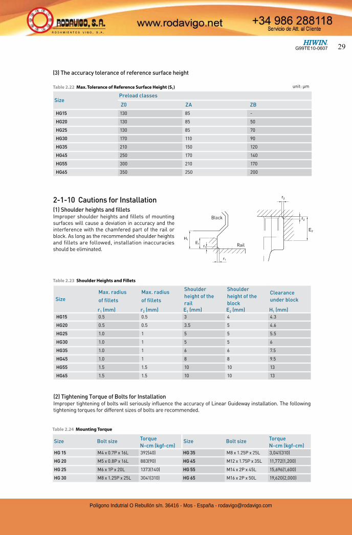
2-1-10 Cautions for Installation(1) Shoulder heights and filletsImproper shoulder heights and fillets of mounting surfaces will cause a deviation in accuracy and the interference with the chamfered part of the rail or block. As long as the recommended shoulder heights and fillets are followed, installation inaccuracies should be eliminated.
Block
Rail
Size
Max. radius
of fillets
Max. radius
of fillets
Shoulder
height of the
rail
Shoulder
height of the
block
Clearance
under block
r1 (mm) r2 (mm) E1 (mm) E2 (mm) H1 (mm)
HG15 0.5 0.5 3 4 4.3
HG20 0.5 0.5 3.5 5 4.6
HG25 1.0 1 5 5 5.5
HG30 1.0 1 5 5 6
HG35 1.0 1 6 6 7.5
HG45 1.0 1 8 8 9.5
HG55 1.5 1.5 10 10 13
HG65 1.5 1.5 10 10 13
Table 2.23 Shoulder Heights and Fillets
Table 2.24 Mounting Torque
(2) Tightening Torque of Bolts for InstallationImproper tightening of bolts will seriously influence the accuracy of Linear Guideway installation. The following tightening torques for different sizes of bolts are recommended.
Size Bolt size Torque Size Bolt size Torque
N-cm (kgf-cm) N-cm (kgf-cm)
HG 15 M4 x 0.7P x 16L 392(40) HG 35 M8 x 1.25P x 25L 3,041(310)
HG 20 M5 x 0.8P x 16L 883(90) HG 45 M12 x 1.75P x 35L 11,772(1,200)
HG 25 M6 x 1P x 20L 1373(140) HG 55 M14 x 2P x 45L 15,696(1,600)
HG 30 M8 x 1.25P x 25L 3041(310) HG 65 M16 x 2P x 50L 19,620(2,000)
G99TE10-0607 29
Polígono Indutrial O Rebullón s/n. 36416 - Mos - España - [email protected]
Linear GuidewaysHG Series
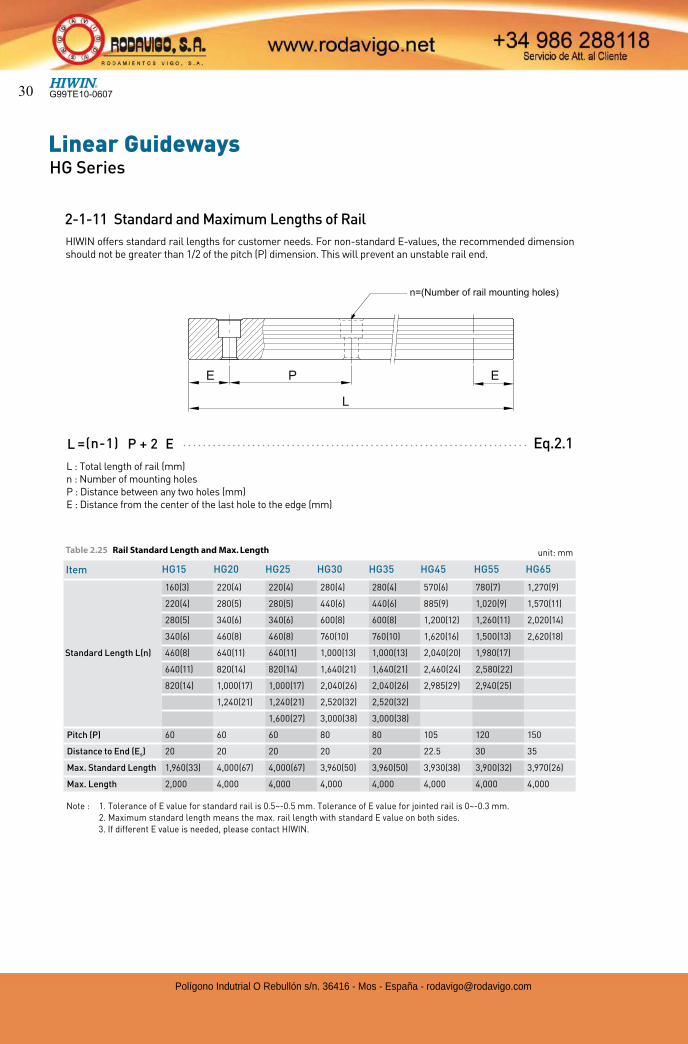
n=(Number of rail mounting holes)
Table 2.25 Rail Standard Length and Max. Length
L : Total length of rail (mm)n : Number of mounting holesP : Distance between any two holes (mm)E : Distance from the center of the last hole to the edge (mm)
2-1-11 Standard and Maximum Lengths of Rail
Eq.2.1=(n-1)L P + 2 E
HIWIN offers standard rail lengths for customer needs. For non-standard E-values, the recommended dimension should not be greater than 1/2 of the pitch (P) dimension. This will prevent an unstable rail end.
Item HG15 HG20 HG25 HG30 HG35 HG45 HG55 HG65
Standard Length L(n)
160(3) 220(4) 220(4) 280(4) 280(4) 570(6) 780(7) 1,270(9)
220(4) 280(5) 280(5) 440(6) 440(6) 885(9) 1,020(9) 1,570(11)
280(5) 340(6) 340(6) 600(8) 600(8) 1,200(12) 1,260(11) 2,020(14)
340(6) 460(8) 460(8) 760(10) 760(10) 1,620(16) 1,500(13) 2,620(18)
460(8) 640(11) 640(11) 1,000(13) 1,000(13) 2,040(20) 1,980(17)
640(11) 820(14) 820(14) 1,640(21) 1,640(21) 2,460(24) 2,580(22)
820(14) 1,000(17) 1,000(17) 2,040(26) 2,040(26) 2,985(29) 2,940(25)
1,240(21) 1,240(21) 2,520(32) 2,520(32)
1,600(27) 3,000(38) 3,000(38)
Pitch (P) 60 60 60 80 80 105 120 150
Distance to End (Es) 20 20 20 20 20 22.5 30 35
Max. Standard Length 1,960(33) 4,000(67) 4,000(67) 3,960(50) 3,960(50) 3,930(38) 3,900(32) 3,970(26)
Max. Length 2,000 4,000 4,000 4,000 4,000 4,000 4,000 4,000
unit: mm
Note : 1. Tolerance of E value for standard rail is 0.5~-0.5 mm. Tolerance of E value for jointed rail is 0~-0.3 mm. 2. Maximum standard length means the max. rail length with standard E value on both sides.
3. If different E value is needed, please contact HIWIN.
G99TE10-060730
Polígono Indutrial O Rebullón s/n. 36416 - Mos - España - [email protected]
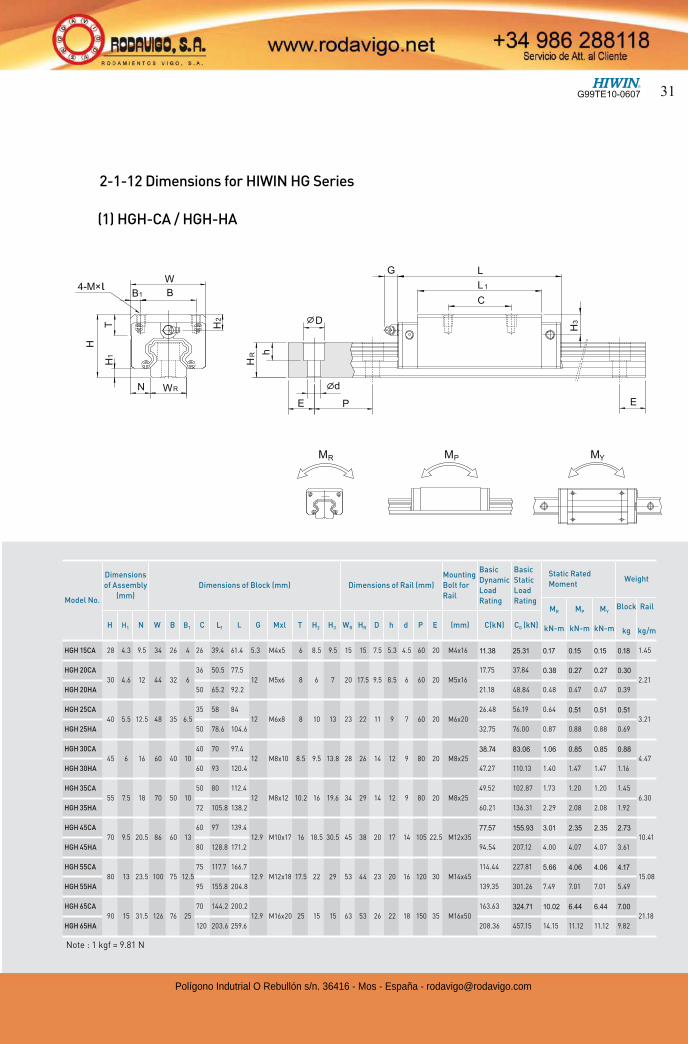
(1) HGH-CA / HGH-HA
l
Model No.
Dimensions
of Assembly
(mm)
Dimensions of Block (mm) Dimensions of Rail (mm)
Mounting
Bolt for
Rail
Basic
Dynamic
Load
Rating
Basic
Static
Load
Rating
Static Rated
MomentWeight
MR
kN-m
MP
kN-m
MY
kN-m
Block
kg
Rail
kg/mH H1 N W B B1 C L1 L G Mxl T H2 H3 WR HR D h d P E (mm) C(kN) C0 (kN)
HGH 15CA 28 4.3 9.5 34 26 4 26 39.4 61.4 5.3 M4x5 6 8.5 9.5 15 15 7.5 5.3 4.5 60 20 M4x16 11.38 25.31 0.17 0.15 0.15 0.18 1.45
HGH 20CA
30 4.6 12 44 32 6
36 50.5 77.5
12 M5x6 8 6 7 20 17.5 9.5 8.5 6 60 20 M5x16
17.75 37.84 0.38 0.27 0.27 0.30
2.21
HGH 20HA 50 65.2 92.2 21.18 48.84 0.48 0.47 0.47 0.39
HGH 25CA
40 5.5 12.5 48 35 6.5
35 58 84
12 M6x8 8 10 13 23 22 11 9 7 60 20 M6x20
26.48 56.19 0.64 0.51 0.51 0.51
3.21
HGH 25HA 50 78.6 104.6 32.75 76.00 0.87 0.88 0.88 0.69
HGH 30CA
45 6 16 60 40 10
40 70 97.4
12 M8x10 8.5 9.5 13.8 28 26 14 12 9 80 20 M8x2538.74 83.06 1.06 0.85 0.85 0.88
4.47
HGH 30HA 60 93 120.4 47.27 110.13 1.40 1.47 1.47 1.16
HGH 35CA
55 7.5 18 70 50 10
50 80 112.4
12 M8x12 10.2 16 19.6 34 29 14 12 9 80 20 M8x25
49.52 102.87 1.73 1.20 1.20 1.45
6.30
HGH 35HA 72 105.8 138.2 60.21 136.31 2.29 2.08 2.08 1.92
HGH 45CA
70 9.5 20.5 86 60 13
60 97 139.4
12.9 M10x17 16 18.5 30.5 45 38 20 17 14 105 22.5 M12x3577.57 155.93 3.01 2.35 2.35 2.73
10.41
HGH 45HA 80 128.8 171.2 94.54 207.12 4.00 4.07 4.07 3.61
HGH 55CA
80 13 23.5 100 75 12.5
75 117.7 166.7
12.9 M12x18 17.5 22 29 53 44 23 20 16 120 30 M14x45
114.44 227.81 5.66 4.06 4.06 4.17
15.08
HGH 55HA 95 155.8 204.8 139.35 301.26 7.49 7.01 7.01 5.49
HGH 65CA
90 15 31.5 126 76 25
70 144.2 200.2
12.9 M16x20 25 15 15 63 53 26 22 18 150 35 M16x50
163.63 324.71 10.02 6.44 6.44 7.00
21.18
HGH 65HA 120 203.6 259.6 208.36 457.15 14.15 11.12 11.12 9.82
Note : 1 kgf = 9.81 N
2-1-12 Dimensions for HIWIN HG Series
G99TE10-0607 31
Polígono Indutrial O Rebullón s/n. 36416 - Mos - España - [email protected]
Linear GuidewaysHG Series
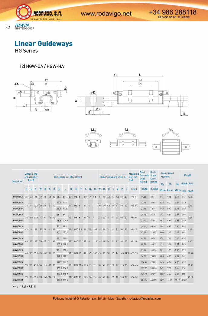
(2) HGW-CA / HGW-HA
Model No.
Dimensions
of Assembly
(mm)
Dimensions of Block (mm) Dimensions of Rail (mm)
Mounting
Bolt for
Rail
Basic
Dynamic
Load
Rating
Basic
Static
Load
Rating
Static Rated
MomentWeight
MR
kN-m
MP
kN-m
MY
kN-m
Block
kg
Rail
kg/mH H1 N W B B1 C L1 L G M T T1 H2 H3 WR HR D h d P E (mm) C(kN) C0 (kN)
HGW 15CA 24 4.3 16 47 38 4.5 30 39.4 61.4 5.3 M5 6 8.9 4.5 5.5 15 15 7.5 5.3 4.5 60 20 M4x16 11.38 25.31 0.17 0.15 0.15 0.17 1.45
HGW 20CA
30 4.6 21.5 63 53 5 40
50.5 77.5
12 M6 8 10 6 7 20 17.5 9.5 8.5 6 60 20 M5x16
17.75 37.84 0.38 0.27 0.27 0.40
2.21
HGW 20HA 65.2 92.2 21.18 48.84 0.48 0.47 0.47 0.52
HGW 25CA
36 5.5 23.5 70 57 6.5 45
58 84
12 M8 8 14 6 9 23 22 11 9 7 60 20 M6x20
26.48 56.19 0.64 0.51 0.51 0.59
3.21
HGW 25HA 78.6 104.6 32.75 76.00 0.87 0.88 0.88 0.80
HGW 30CA
42 6 31 90 72 9 52
70 97.4
12 M10 8.5 16 6.5 10.8 28 26 14 12 9 80 20 M8x2538.74 83.06 1.06 0.85 0.85 1.09
4.47
HGW 30HA 93 120.4 47.27 110.13 1.40 1.47 1.47 1.44
HGW 35CA
48 7.5 33 100 82 9 62
80 112.4
12 M10 10.1 18 9 12.6 34 29 14 12 9 80 20 M8x25
49.52 102.87 1.73 1.20 1.20 1.56
6.30
HGW 35HA 105.8 138.2 60.21 136.31 2.29 2.08 2.08 2.06
HGW 45CA
60 9.5 37.5 120 100 10 80
97 139.4
12.9 M12 15.1 22 8.5 20.5 45 38 20 17 14 105 22.5 M12x3577.57 155.93 3.01 2.35 2.35 2.79
10.41
HGW 45HA 128.8 171.2 94.54 207.12 4.00 4.07 4.07 3.69
HGW 55CA
70 13 43.5 140 116 12 95
117.7 166.7
12.9 M14 17.5 26.5 12 19 53 44 23 20 16 120 30 M14x45
114.44 227.81 5.66 4.06 4.06 4.52
15.08
HGW 55HA 155.8 204.8 139.35 301.26 7.49 7.01 7.01 5.96
HGW 65CA
90 15 53.5 170 142 14 110
144.2 200.2
12.9 M16 25 37.5 15 15 63 53 26 22 18 150 35 M16x50
163.63 324.71 10.02 6.44 6.44 9.17
21.18
HGW 65HA 203.6 259.6 208.36 457.15 14.15 11.12 11.12 12.89
Note : 1 kgf = 9.81 N
G99TE10-060732
Polígono Indutrial O Rebullón s/n. 36416 - Mos - España - [email protected]
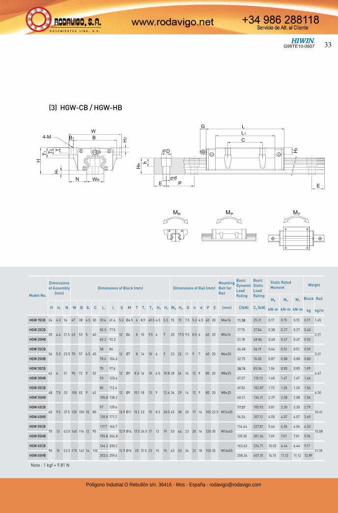
(3) HGW-CB / HGW-HB
Model No.
Dimensions
of Assembly
(mm)
Dimensions of Block (mm) Dimensions of Rail (mm)
Mounting
Bolt for
Rail
Basic
Dynamic
Load
Rating
Basic
Static
Load
Rating
Static Rated
MomentWeight
MR
kN-m
MP
kN-m
MY
kN-m
Block
kg
Rail
kg/mH H1 N W B B1 C L1 L G M T T1 T2 H2 H3 WR HR D h d P E (mm) C(kN) C0 (kN)
HGW 15CB 24 4.3 16 47 38 4.5 30 39.4 61.4 5.3 Ø4.5 6 8.9 69.5 4.5 5.5 15 15 7.5 5.3 4.5 60 20 M4x16 11.38 25.31 0.17 0.15 0.15 0.17 1.45
HGW 20CB
30 4.6 21.5 63 53 5 40
50.5 77.5
12 Ø6 8 10 9.5 6 7 20 17.5 9.5 8.5 6 60 20 M5x16
17.75 37.84 0.38 0.27 0.27 0.40
2.21
HGW 20HB 65.2 92.2 21.18 48.84 0.48 0.47 0.47 0.52
HGW 25CB
36 5.5 23.5 70 57 6.5 45
58 84
12 Ø7 8 14 10 6 9 23 22 11 9 7 60 20 M6x20
26.48 56.19 0.64 0.51 0.51 0.59
3.21
HGW 25HB 78.6 104.6 32.75 76.00 0.87 0.88 0.88 0.80
HGW 30CB
42 6 31 90 72 9 52
70 97.4
12 Ø9 8.5 16 10 6.5 10.8 28 26 14 12 9 80 20 M8x2538.74 83.06 1.06 0.85 0.85 1.09
4.47
HGW 30HB 93 120.4 47.27 110.13 1.40 1.47 1.47 1.44
HGW 35CB
48 7.5 33 100 82 9 62
80 112.4
12 Ø9 10.1 18 13 9 12.6 34 29 14 12 9 80 20 M8x25
49.52 102.87 1.73 1.20 1.20 1.56
6.30
HGW 35HB 105.8 138.2 60.21 136.31 2.29 2.08 2.08 2.06
HGW 45CB
60 9.5 37.5 120 100 10 80
97 139.4
12.9 Ø11 15.1 22 15 8.5 20.5 45 38 20 17 14 105 22.5 M12x3577.57 155.93 3.01 2.35 2.35 2.79
10.41
HGW 45HB 128.8 171.2 94.54 207.12 4.00 4.07 4.07 3.69
HGW 55CB
70 13 43.5 140 116 12 95
117.7 166.7
12.9 Ø14 17.5 26.5 17 12 19 53 44 23 20 16 120 30 M14x45
114.44 227.81 5.66 4.06 4.06 4.52
15.08
HGW 55HB 155.8 204.8 139.35 301.26 7.49 7.01 7.01 5.96
HGW 65CB
90 15 53.5 170 142 14 110
144.2 200.2
12.9 Ø16 25 37.5 23 15 15 63 53 26 22 18 150 35 M16x50
163.63 324.71 10.02 6.44 6.44 9.17
21.18
HGW 65HB 203.6 259.6 208.36 457.15 14.15 11.12 11.12 12.89
Note : 1 kgf = 9.81 N
G99TE10-0607 33
Polígono Indutrial O Rebullón s/n. 36416 - Mos - España - [email protected]
Linear GuidewaysHG Series
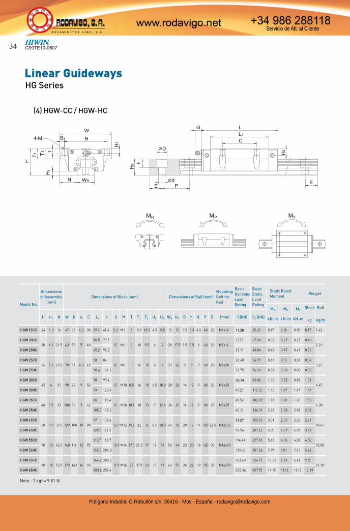
(4) HGW-CC / HGW-HC
Model No.
Dimensions
of Assembly
(mm)
Dimensions of Block (mm) Dimensions of Rail (mm)
Mounting
Bolt for
Rail
Basic
Dynamic
Load
Rating
Basic
Static
Load
Rating
Static Rated
MomentWeight
MR
kN-m
MP
kN-m
MY
kN-m
Block
kg
Rail
kg/mH H1 N W B B1 C L1 L G M T T1 T2 H2 H3 WR HR D h d P E (mm) C(kN) C0 (kN)
HGW 15CC 24 4.3 16 47 38 4.5 30 39.4 61.4 5.3 M5 6 8.9 69.5 4.5 5.5 15 15 7.5 5.3 4.5 60 20 M4x16 11.38 25.31 0.17 0.15 0.15 0.17 1.45
HGW 20CC
30 4.6 21.5 63 53 5 40
50.5 77.5
12 M6 8 10 9.5 6 7 20 17.5 9.5 8.5 6 60 20 M5x16
17.75 37.84 0.38 0.27 0.27 0.40
2.21
HGW 20HC 65.2 92.2 21.18 48.84 0.48 0.47 0.47 0.52
HGW 25CC
36 5.5 23.5 70 57 6.5 45
58 84
12 M8 8 14 10 6 9 23 22 11 9 7 60 20 M6x20
26.48 56.19 0.64 0.51 0.51 0.59
3.21
HGW 25HC 78.6 104.6 32.75 76.00 0.87 0.88 0.88 0.80
HGW 30CC
42 6 31 90 72 9 52
70 97.4
12 M10 8.5 16 10 6.5 10.8 28 26 14 12 9 80 20 M8x2538.74 83.06 1.06 0.85 0.85 1.09
4.47
HGW 30HC 93 120.4 47.27 110.13 1.40 1.47 1.47 1.44
HGW 35CC
48 7.5 33 100 82 9 62
80 112.4
12 M10 10.1 18 13 9 12.6 34 29 14 12 9 80 20 M8x25
49.52 102.87 1.73 1.20 1.20 1.56
6.30
HGW 35HC 105.8 138.2 60.21 136.31 2.29 2.08 2.08 2.06
HGW 45CC
60 9.5 37.5 120 100 10 80
97 139.4
12.9 M12 15.1 22 15 8.5 20.5 45 38 20 17 14 105 22.5 M12x3577.57 155.93 3.01 2.35 2.35 2.79
10.41
HGW 45HC 128.8 171.2 94.54 207.12 4.00 4.07 4.07 3.69
HGW 55CC
70 13 43.5 140 116 12 95
117.7 166.7
12.9 M14 17.5 26.5 17 12 19 53 44 23 20 16 120 30 M14x45
114.44 227.81 5.66 4.06 4.06 4.52
15.08
HGW 55HC 155.8 204.8 139.35 301.26 7.49 7.01 7.01 5.96
HGW 65CC
90 15 53.5 170 142 14 110
144.2 200.2
12.9 M16 25 37.5 23 15 15 63 53 26 22 18 150 35 M16x50
163.63 324.71 10.02 6.44 6.44 9.17
21.18
HGW 65HC 203.6 259.6 208.36 457.15 14.15 11.12 11.12 12.89
Note : 1 kgf = 9.81 N
G99TE10-060734
Polígono Indutrial O Rebullón s/n. 36416 - Mos - España - [email protected]
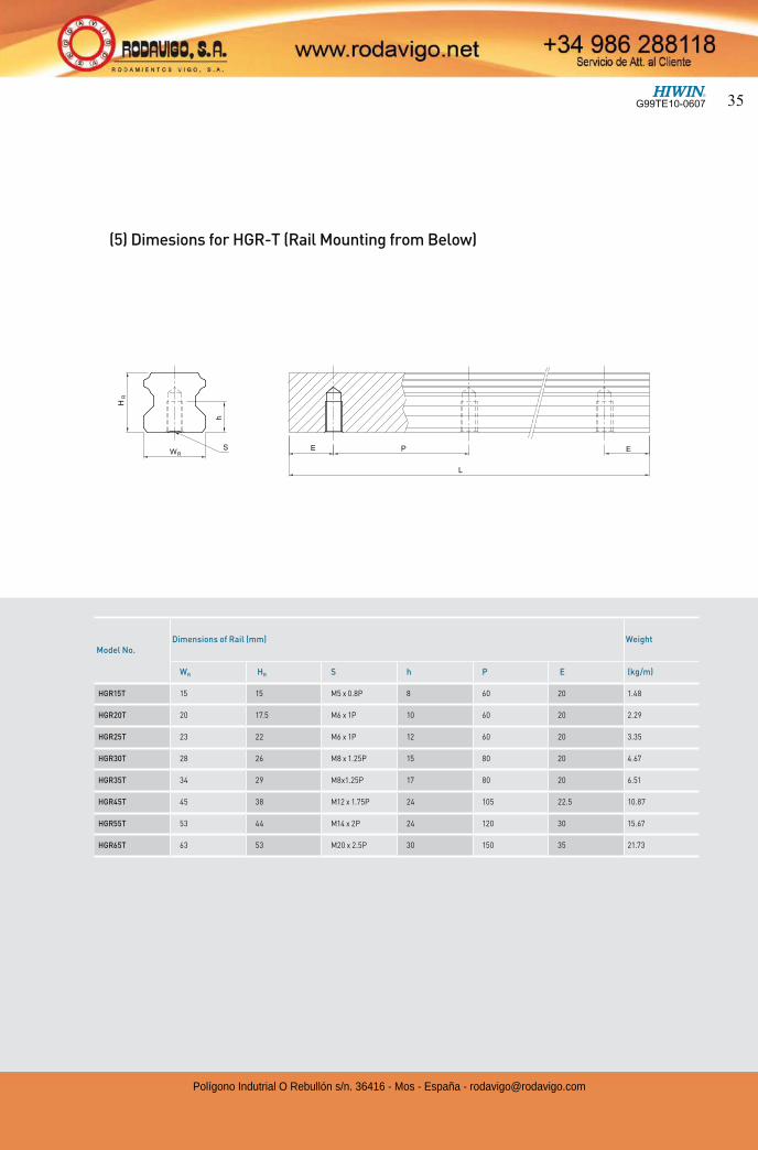
(5) Dimesions for HGR-T (Rail Mounting from Below)
Model No.Dimensions of Rail (mm) Weight
WR HR S h P E (kg/m)
HGR15T 15 15 M5 x 0.8P 8 60 20 1.48
HGR20T 20 17.5 M6 x 1P 10 60 20 2.29
HGR25T 23 22 M6 x 1P 12 60 20 3.35
HGR30T 28 26 M8 x 1.25P 15 80 20 4.67
HGR35T 34 29 M8x1.25P 17 80 20 6.51
HGR45T 45 38 M12 x 1.75P 24 105 22.5 10.87
HGR55T 53 44 M14 x 2P 24 120 30 15.67
HGR65T 63 53 M20 x 2.5P 30 150 35 21.73
G99TE10-0607 35
Polígono Indutrial O Rebullón s/n. 36416 - Mos - España - [email protected]
Linear GuidewaysEG Series
2-2-1 Features of the EG Series Linear Guideway
The design of the EG series offers a low profile, high load capacity, and high rigidity. It also features an equal load rating in all four directions and self-aligning capability to absorb installation-error, allowing for higher accuracies. Additionally, the lower assembly height and the shorter length make the EG series more suitable for high-speed, automation machines and applications where space is limited.The retainer is designed to hold the balls in the block even when it is removed from the rail.
2-2-3 Model Number of EG SeriesEG series linear guideways are classified into non-interchangeable and interchangeable types. The sizes of these two types are the same as one another. The main difference is that the interchangeable type of blocks and rails can be freely exchanged and they can maintain P-class accuracy. Because of strict dimensional control, the interchangeable type linear guideways are a wise choice for customers when rails do not need to be matched for an axis. The model number of the EG series identifies the size, type, accuracy class, preload class, etc.
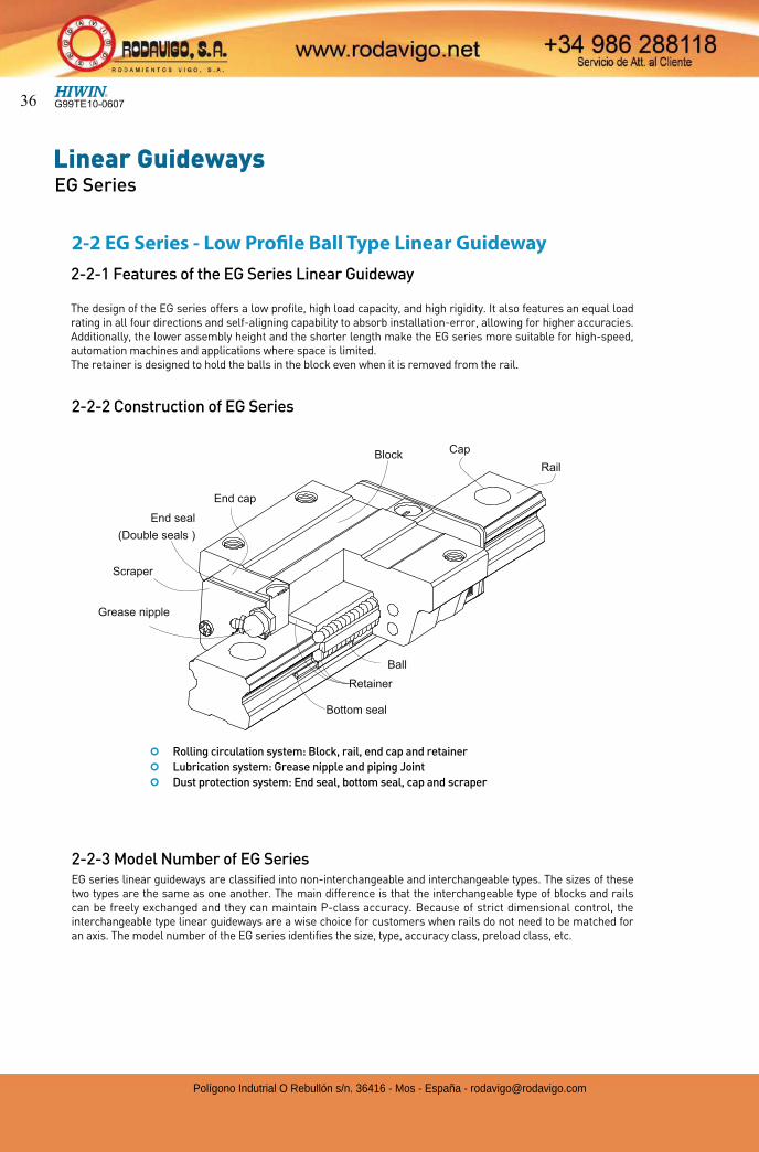
Ball
End seal
(Double seals )
Grease nipple
End cap
BlockRail
Retainer
Bottom seal
2-2-2 Construction of EG Series
2-2 EG Series - Low Profile Ball Type Linear Guideway
¢ Rolling circulation system: Block, rail, end cap and retainer
¢ Lubrication system: Grease nipple and piping Joint
¢ Dust protection system: End seal, bottom seal, cap and scraper
Cap
Scraper
G99TE10-060736
Polígono Indutrial O Rebullón s/n. 36416 - Mos - España - [email protected]
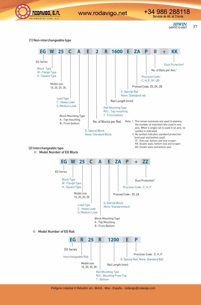
(1) Non-interchangeable type
(2) Interchangeable type ¢ Model Number of EG Block
¢ Model Number of EG Rail
EG Series
Block Type
W : Flange Type
H : Square Type
Block Mounting Type
A : Top Mounting
B : From Bottom
E: Special Block
None: Standard block
Dust Protection2
Precision Code : C, H, P
Preload Code : Z0, ZA
EG Series
Rail Mounting Type
R/U : Mounting From Top
T : Bottom
Rail Length (mm)
E: Special Rail, None: Standard Rail
Precision Code : C, H, PInterchangeable Rail
EG Series
Block Type
W : Flange Type
H : Square Type
Model size
15, 20, 25, 30,
No. of Blocks per Rail
Rail Length (mm)
E: Special Rail
None: Standard rail
Rail Mounting Type
R/U : Top mounting
T : From bottom
Preload Code: Z0, ZA, ZB
Precision Code:
C, H, P, SP, UP
No. of Rails per Axis 1
Dust Protection2
EG W 25 C A E 2 R 1600 E ZA P II + KK
Load Type
C : Heavy Load
S: Medium Load
Block Mounting Type
A : Top mounting
B : From bottom
Model size
15, 20, 25, 30
Load Type
C : Heavy Load S: Medium Load
EG W 25 C A E ZA P + ZZ
Model size
15, 20, 25, 30
EG R 25 R 1200 E P
Note: 1. The roman numerals are used to express the number of matched rails used in one axis. When a single rail is used in an axis, no symbol is indicated.
2. No symbol indicates standard protection (end seal and bottom seal).ZZ : End seal, bottom seal and scraperKK: Double seals, bottom seal and scraper.
DD: Double seals and bottom seal
E: Special Block
None: Standard Block
G99TE10-0607 37
Polígono Indutrial O Rebullón s/n. 36416 - Mos - España - [email protected]
Linear GuidewaysEG Series
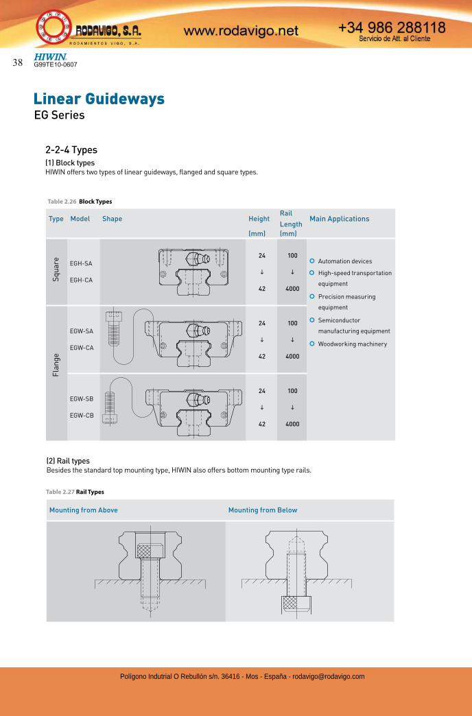
2-2-4 Types(1) Block typesHIWIN offers two types of linear guideways, flanged and square types.
Type Model Shape HeightRail
LengthMain Applications
(mm) (mm)
EGH-SA
EGH-CA
24
i
42
100
i
4000
¢ Automation devices
¢ High-speed transportation
equipment
¢ Precision measuring
equipment
¢ Semiconductor
manufacturing equipment
¢ Woodworking machinery
EGW-SA
EGW-CA
24
i
42
100
i
4000
EGW-SB
EGW-CB
24
i
42
100
i
4000
Sq
uar
e F
lan
ge
(2) Rail typesBesides the standard top mounting type, HIWIN also offers bottom mounting type rails.
Table 2.27 Rail Types
Mounting from Above Mounting from Below
Table 2.26 Block Types
G99TE10-060738
Polígono Indutrial O Rebullón s/n. 36416 - Mos - España - [email protected]
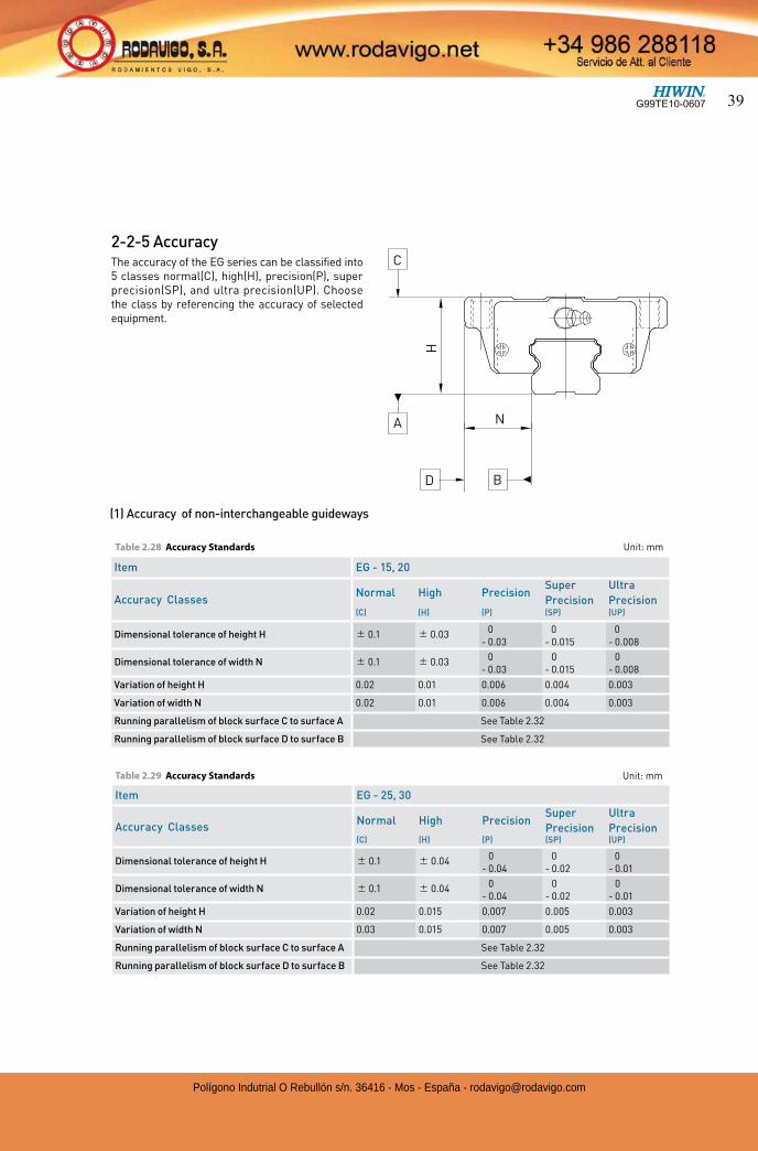
2-2-5 AccuracyThe accuracy of the EG series can be classified into 5 classes normal(C), high(H), precision(P), super precision(SP), and ultra precision(UP). Choose the class by referencing the accuracy of selected equipment.
Table 2.28 Accuracy Standards Unit: mm
(1) Accuracy of non-interchangeable guideways
Item EG - 25, 30
Accuracy ClassesNormal High Precision
Super
Precision
Ultra
Precision (C) (H) (P) (SP) (UP)
Dimensional tolerance of height H 0.1 0.04 0- 0.04
0- 0.02
0- 0.01
Dimensional tolerance of width N 0.1 0.04 0- 0.04
0- 0.02
0- 0.01
Variation of height H 0.02 0.015 0.007 0.005 0.003
Variation of width N 0.03 0.015 0.007 0.005 0.003
Running parallelism of block surface C to surface A See Table 2.32
Running parallelism of block surface D to surface B See Table 2.32
Item EG - 15, 20
Accuracy ClassesNormal High Precision
Super
Precision
Ultra
Precision (C) (H) (P) (SP) (UP)
Dimensional tolerance of height H 0.1 0.03 0- 0.03
0- 0.015
0- 0.008
Dimensional tolerance of width N 0.1 0.03 0- 0.03
0- 0.015
0- 0.008
Variation of height H 0.02 0.01 0.006 0.004 0.003
Variation of width N 0.02 0.01 0.006 0.004 0.003
Running parallelism of block surface C to surface A See Table 2.32
Running parallelism of block surface D to surface B See Table 2.32
Table 2.29 Accuracy Standards Unit: mm
HN
D B
A
C
G99TE10-0607 39
Polígono Indutrial O Rebullón s/n. 36416 - Mos - España - [email protected]
Linear GuidewaysEG Series
(2) Accuracy of interchangeable
Table 2.30 Accuracy Standards Unit: mm
Item EG - 15, 20
Accuracy Classes Normal High Precision(C) (H) (P)
Dimensional tolerance of height H 0.1 0.03 0.015
Dimensional tolerance of width N 0.1 0.03 0.015
Variation of height H 0.02 0.01 0.006
Variation of width N 0.02 0.01 0.006
Running parallelism of block surface C to surface A See Table 2.32
Running parallelism of block surface D to surface B See Table 2.32
Item EG - 25, 30
Accuracy Classes Normal High Precision(C) (H) (P)
Dimensional tolerance of height H 0.1 0.04 0.02
Dimensional tolerance of width N 0.1 0.04 0.02
Variation of height H 0.02 0.015 0.007
Variation of width N 0.03 0.015 0.007
Running parallelism of block surface C to surface A See Table 2.32
Running parallelism of block surface D to surface B See Table 2.32
Table 2.31 Accuracy Standards Unit: mm
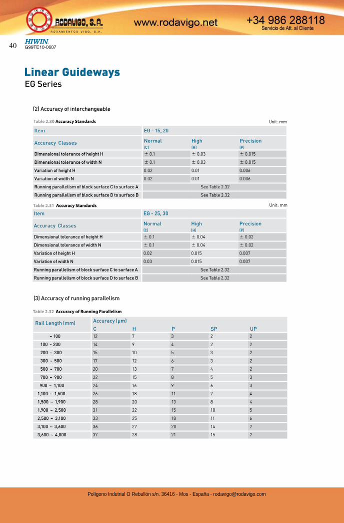
(3) Accuracy of running parallelism
Rail Length (mm) Accuracy (µm)
C H P SP UP
~ 100 12 7 3 2 2
100 ~ 200 14 9 4 2 2
200 ~ 300 15 10 5 3 2
300 ~ 500 17 12 6 3 2
500 ~ 700 20 13 7 4 2
700 ~ 900 22 15 8 5 3
900 ~ 1,100 24 16 9 6 3
1,100 ~ 1,500 26 18 11 7 4
1,500 ~ 1,900 28 20 13 8 4
1,900 ~ 2,500 31 22 15 10 5
2,500 ~ 3,100 33 25 18 11 6
3,100 ~ 3,600 36 27 20 14 7
3,600 ~ 4,000 37 28 21 15 7
Table 2.32 Accuracy of Running Parallelism
G99TE10-060740
Polígono Indutrial O Rebullón s/n. 36416 - Mos - España - [email protected]
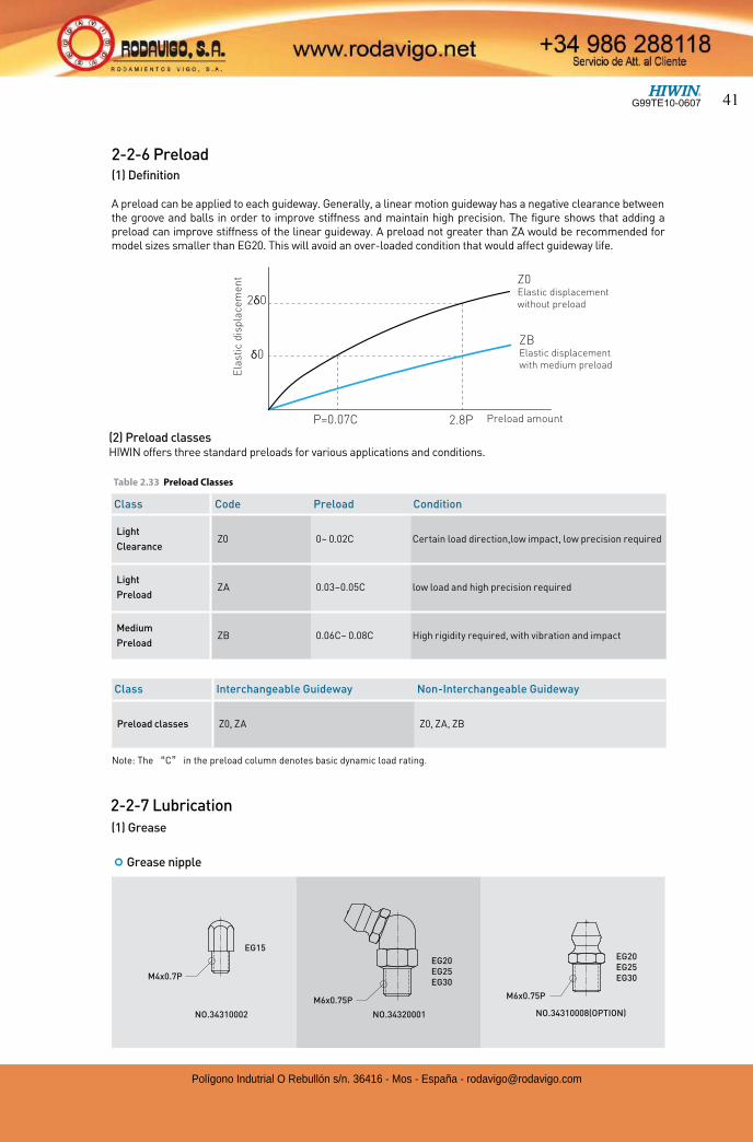
2-2-6 Preload(1) Definition
A preload can be applied to each guideway. Generally, a linear motion guideway has a negative clearance between the groove and balls in order to improve stiffness and maintain high precision. The figure shows that adding a preload can improve stiffness of the linear guideway. A preload not greater than ZA would be recommended for model sizes smaller than EG20. This will avoid an over-loaded condition that would affect guideway life.
2-2-7 Lubrication
Class Code Preload Condition
Light
ClearanceZ0 0~ 0.02C Certain load direction,low impact, low precision required
Light
PreloadZA 0.03~0.05C low load and high precision required
Medium
PreloadZB 0.06C~ 0.08C High rigidity required, with vibration and impact
Table 2.33 Preload Classes
(2) Preload classesHIWIN offers three standard preloads for various applications and conditions.
Class Interchangeable Guideway Non-Interchangeable Guideway
Preload classes Z0, ZA Z0, ZA, ZB
(1) Grease
¢ Grease nipple
P=0.07C
Ela
sti
c d
isp
lace
me
nt
2δ0
δ0
Preload amount 2.8P
ZBElastic displacement
with medium preload
Z0Elastic displacement
without preload
NO.34310002 NO.34320001
EG15
EG20
NO.34310008(OPTION)
EG30EG25
EG30EG25EG20
M6x0.75PM6x0.75P
M4x0.7P
Note: The C in the preload column denotes basic dynamic load rating.
G99TE10-0607 41
Polígono Indutrial O Rebullón s/n. 36416 - Mos - España - [email protected]
Linear GuidewaysEG Series
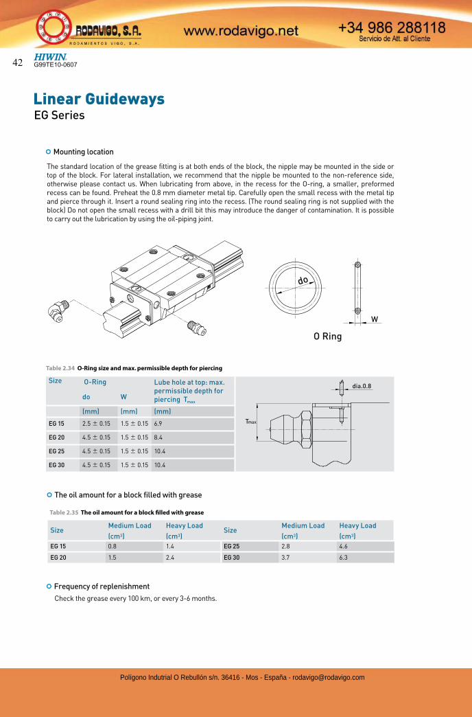
The standard location of the grease fitting is at both ends of the block, the nipple may be mounted in the side or top of the block. For lateral installation, we recommend that the nipple be mounted to the non-reference side, otherwise please contact us. When lubricating from above, in the recess for the O-ring, a smaller, preformed recess can be found. Preheat the 0.8 mm diameter metal tip. Carefully open the small recess with the metal tip and pierce through it. Insert a round sealing ring into the recess. (The round sealing ring is not supplied with the block) Do not open the small recess with a drill bit this may introduce the danger of contamination. It is possible to carry out the lubrication by using the oil-piping joint.
¢ Mounting location
Size O-Ring Lube hole at top: max.
permissible depth for piercing Tmax
do W
(mm) (mm) (mm)
EG 15 2.5 0.15 1.5 0.15 6.9
EG 20 4.5 0.15 1.5 0.15 8.4
EG 25 4.5 0.15 1.5 0.15 10.4
EG 30 4.5 0.15 1.5 0.15 10.4
¢ The oil amount for a block filled with grease
Table 2.34 O-Ring size and max. permissible depth for piercing
Table 2.35 The oil amount for a block filled with grease
¢ Frequency of replenishment
Check the grease every 100 km, or every 3-6 months.
Size Medium Load Heavy Load
Size Medium Load Heavy Load
(cm3) (cm3) (cm3) (cm3)
EG 15 0.8 1.4 EG 25 2.8 4.6
EG 20 1.5 2.4 EG 30 3.7 6.3
dia.0.8
Tmax
do
W
O Ring
G99TE10-060742
Polígono Indutrial O Rebullón s/n. 36416 - Mos - España - [email protected]
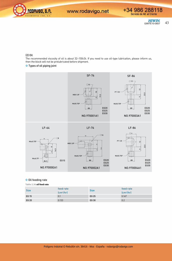
Size feed rate
Sizefeed rate
(cm3/hr) (cm3/hr)
EG 15 0.1 EG 25 0.167
EG 20 0.133 EG 30 0.2
(2) OilThe recommended viscosity of oil is about 32~150cSt. If you need to use oil-type lubrication, please inform us, then the block will not be prelubricated before shipment.
¢ Types of oil piping joint
¢ Oil feeding rate
Table 2.36 oil feed rate
31
0
19
.5
NO.97000EA1 NO.970002A1
16
.5
48
10
LF-64
19
.5
EG15
18
NO.970001A1
LF-76
SF-76
10
3
EG30NO.970004A1
EG30
23
.52
3.5
EG25EG20
EG25EG30
EG20
12
51
2
NO.970003A1
LF-86
SF-86
12
5
EG25EG20
EG25EG30
EG20
M6X0.75P
M8X1.0P
8
10
M6x0.75P
M4x0.7P
M6X0.75P
M8X1.0P
M6X0.75P
PT 1/8
M6X0.75P
PT 1/8
12
10
Ø8
Ø8Ø8Ø6.5
Ø8
G99TE10-0607 43
Polígono Indutrial O Rebullón s/n. 36416 - Mos - España - [email protected]
Linear GuidewaysEG Series
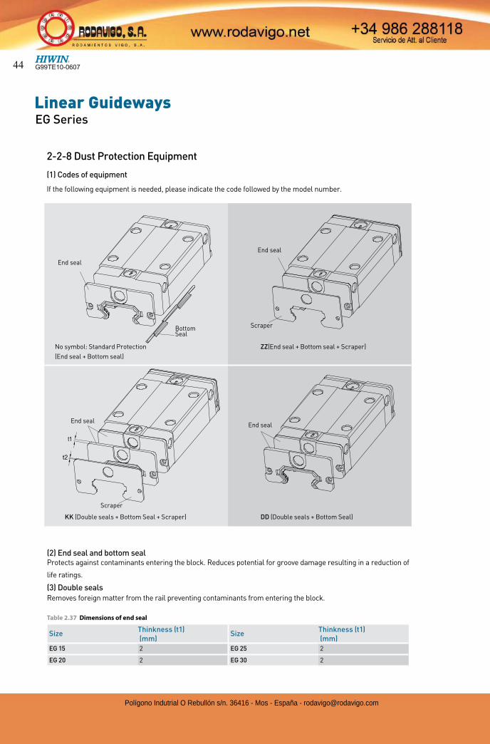
(2) End seal and bottom seal Protects against contaminants entering the block. Reduces potential for groove damage resulting in a reduction of
life ratings.
(3) Double sealsRemoves foreign matter from the rail preventing contaminants from entering the block.
Size Thinkness (t1)
SizeThinkness (t1)
(mm) (mm)
EG 15 2 EG 25 2
EG 20 2 EG 30 2
Table 2.37 Dimensions of end seal
2-2-8 Dust Protection Equipment
(1) Codes of equipment
If the following equipment is needed, please indicate the code followed by the model number.
Scraper
Bottom Seal
End seal
End seal
KK (Double seals + Bottom Seal + Scraper)
No symbol: Standard Protection
(End seal + Bottom seal)
Scraper
End seal
End seal
DD (Double seals + Bottom Seal)
ZZ(End seal + Bottom seal + Scraper)
G99TE10-060744
Polígono Indutrial O Rebullón s/n. 36416 - Mos - España - [email protected]
Size Thinkness (t2)
SizeThinkness (t2)
(mm) (mm)
EG 15 0.8 EG 25 1
EG 20 0.8 EG 30 1
Table 2.38 Dimensions of Scraper
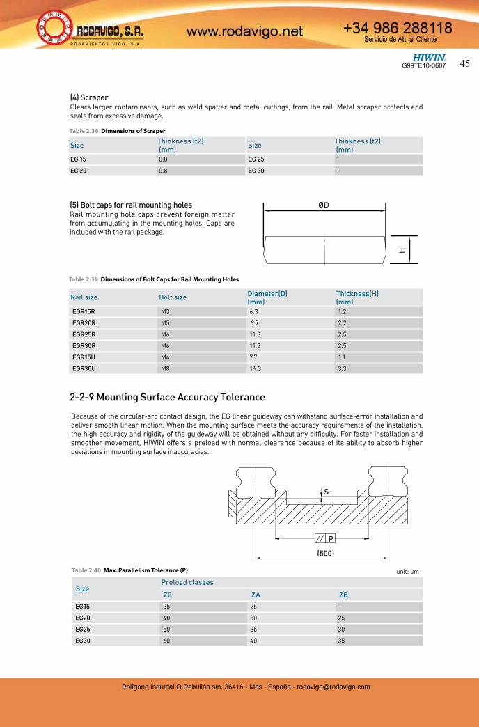
(4) ScraperClears larger contaminants, such as weld spatter and metal cuttings, from the rail. Metal scraper protects end seals from excessive damage.
(5) Bolt caps for rail mounting holesRail mounting hole caps prevent foreign matter from accumulating in the mounting holes. Caps are included with the rail package.
Rail size Bolt size Diameter(D) Thickness(H) (mm) (mm)
EGR15R M3 6.3 1.2
EGR20R M5 9.7 2.2
EGR25R M6 11.3 2.5
EGR30R M6 11.3 2.5
EGR15U M4 7.7 1.1
EGR30U M8 14.3 3.3
Table 2.39 Dimensions of Bolt Caps for Rail Mounting Holes
2-2-9 Mounting Surface Accuracy Tolerance
Because of the circular-arc contact design, the EG linear guideway can withstand surface-error installation and deliver smooth linear motion. When the mounting surface meets the accuracy requirements of the installation, the high accuracy and rigidity of the guideway will be obtained without any difficulty. For faster installation and smoother movement, HIWIN offers a preload with normal clearance because of its ability to absorb higher deviations in mounting surface inaccuracies.
Ø
(500)
P
S 1
SizePreload classes
Z0 ZA ZB
EG15 35 25 -
EG20 40 30 25
EG25 50 35 30
EG30 60 40 35
Table 2.40 Max. Parallelism Tolerance (P) unit: µm
G99TE10-0607 45
Polígono Indutrial O Rebullón s/n. 36416 - Mos - España - [email protected]
Linear GuidewaysEG Series
Size
Max. chamfers
of the rail
Max. chamfers
of the rail
Shoulder
height of the
rail
Shoulder
height of the
block
Clearance
under block
r1 (mm) r2 (mm) E1 (mm) E2 (mm) H1 (mm)
EG15 0.5 0.5 2.7 5.0 4.5
EG20 0.5 0.5 5.0 7.0 6.0
EG25 1.0 1.0 5.0 7.5 7.0
EG30 1.0 1.0 7.0 7.0 10.0
SizePreload classes
Z0 ZA ZB
EG15 180 100 -
EG20 180 100 80
EG25 200 120 100
EG30 240 150 120
Table 2.41 Max. Tolerance of Reference Surface Height (S1) unit: µm
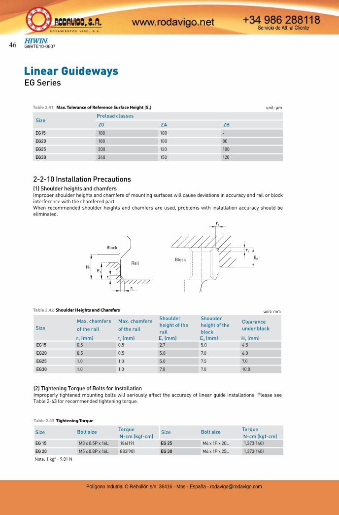
2-2-10 Installation Precautions(1) Shoulder heights and chamfersImproper shoulder heights and chamfers of mounting surfaces will cause deviations in accuracy and rail or block interference with the chamfered part.When recommended shoulder heights and chamfers are used, problems with installation accuracy should be eliminated.
Table 2.42 Shoulder Heights and Chamfers
Size Bolt size TorqueSize Bolt size Torque
N-cm (kgf-cm) N-cm (kgf-cm)
EG 15 M3 x 0.5P x 16L 186(19) EG 25 M6 x 1P x 20L 1,373(140)
EG 20 M5 x 0.8P x 16L 883(90) EG 30 M6 x 1P x 25L 1,373(140)
Table 2.43 Tightening Torque
(2) Tightening Torque of Bolts for InstallationImproperly tightened mounting bolts will seriously affect the accuracy of linear guide installations. Please see Table 2-43 for recommended tightening torque.
Note: 1 kgf = 9.81 N
unit: mm
1HE1
E2
1r
1r
2r
2r
BlockRail
Block
G99TE10-060746
Polígono Indutrial O Rebullón s/n. 36416 - Mos - España - [email protected]
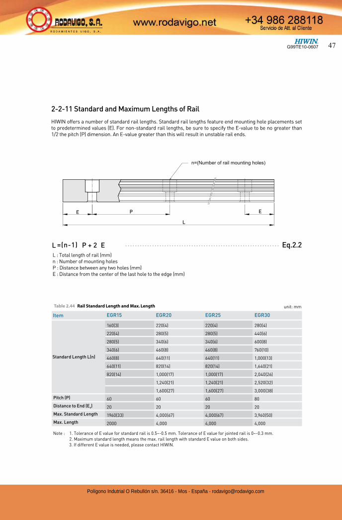
2-2-11 Standard and Maximum Lengths of Rail
HIWIN offers a number of standard rail lengths. Standard rail lengths feature end mounting hole placements set to predetermined values (E). For non-standard rail lengths, be sure to specify the E-value to be no greater than 1/2 the pitch (P) dimension. An E-value greater than this will result in unstable rail ends.
L : Total length of rail (mm)n : Number of mounting holesP : Distance between any two holes (mm)E : Distance from the center of the last hole to the edge (mm)
Eq.2.2=(n-1)L P + 2 E
Item EGR15 EGR20 EGR25 EGR30
Standard Length L(n)
160(3) 220(4) 220(4) 280(4)
220(4) 280(5) 280(5) 440(6)
280(5) 340(6) 340(6) 600(8)
340(6) 460(8) 460(8) 760(10)
460(8) 640(11) 640(11) 1,000(13)
640(11) 820(14) 820(14) 1,640(21)
820(14) 1,000(17) 1,000(17) 2,040(26)
1,240(21) 1,240(21) 2,520(32)
1,600(27) 1,600(27) 3,000(38)
Pitch (P) 60 60 60 80
Distance to End (Es) 20 20 20 20
Max. Standard Length 1960(33) 4,000(67) 4,000(67) 3,960(50)
Max. Length 2000 4,000 4,000 4,000
unit: mmTable 2.44 Rail Standard Length and Max. Length
L
E P E
n=(Number of rail mounting holes)
Note : 1. Tolerance of E value for standard rail is 0.5~-0.5 mm. Tolerance of E value for jointed rail is 0~-0.3 mm. 2. Maximum standard length means the max. rail length with standard E value on both sides.
3. If different E value is needed, please contact HIWIN.
G99TE10-0607 47
Polígono Indutrial O Rebullón s/n. 36416 - Mos - España - [email protected]
Linear GuidewaysEG Series
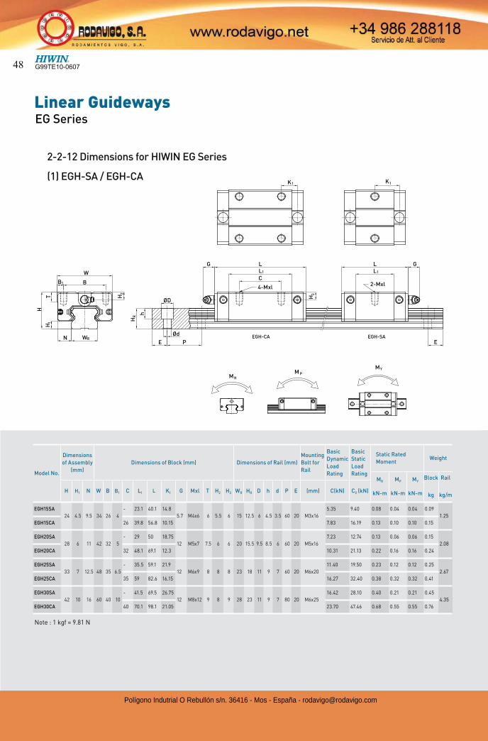
2-2-12 Dimensions for HIWIN EG Series
(1) EGH-SA / EGH-CA
Model No.
Dimensions
of Assembly
(mm)
Dimensions of Block (mm) Dimensions of Rail (mm)
Mounting
Bolt for
Rail
Basic
Dynamic
Load
Rating
Basic
Static
Load
Rating
Static Rated
MomentWeight
MR
kN-m
MP
kN-m
MY
kN-m
Block
kg
Rail
kg/mH H1 N W B B1 C L1 L K1 G Mxl T H2 H3 WR HR D h d P E (mm) C(kN) C0 (kN)
EGH15SA
24 4.5 9.5 34 26 4
- 23.1 40.1 14.8
5.7 M4x6 6 5.5 6 15 12.5 6 4.5 3.5 60 20 M3x16
5.35 9.40 0.08 0.04 0.04 0.09
1.25
EGH15CA 26 39.8 56.8 10.15 7.83 16.19 0.13 0.10 0.10 0.15
EGH20SA
28 6 11 42 32 5
- 29 50 18.75
12 M5x7 7.5 6 6 20 15.5 9.5 8.5 6 60 20 M5x16
7.23 12.74 0.13 0.06 0.06 0.15
2.08
EGH20CA 32 48.1 69.1 12.3 10.31 21.13 0.22 0.16 0.16 0.24
EGH25SA
33 7 12.5 48 35 6.5
- 35.5 59.1 21.9
12 M6x9 8 8 8 23 18 11 9 7 60 20 M6x20
11.40 19.50 0.23 0.12 0.12 0.25
2.67
EGH25CA 35 59 82.6 16.15 16.27 32.40 0.38 0.32 0.32 0.41
EGH30SA
42 10 16 60 40 10
- 41.5 69.5 26.75
12 M8x12 9 8 9 28 23 11 9 7 80 20 M6x25
16.42 28.10 0.40 0.21 0.21 0.45
4.35
EGH30CA 40 70.1 98.1 21.05 23.70 47.46 0.68 0.55 0.55 0.76
Note : 1 kgf = 9.81 N
1
RWN
H
H
W
B1B
T
RH
E
Ød
P
ØD
H2
h
G
EGH-CA
LL
1
4-Mxl
C
H3
1K
EGH-SAE
GLL1
2-Mxl
1K
RMP
YMM
G99TE10-060748
Polígono Indutrial O Rebullón s/n. 36416 - Mos - España - [email protected]
H
WRN
T
H
W
BB1
T1
1
E P
Ød
2H
h
HR
G
ØD
EGW-CA
C
LL1
4-M
H3
K1
EGW-SAE
GLL1
2-M
K1
M RM P
YM
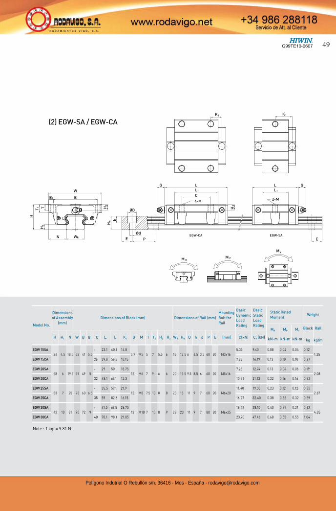
(2) EGW-SA / EGW-CA
Note : 1 kgf = 9.81 N
Model No.
Dimensions
of Assembly
(mm)
Dimensions of Block (mm) Dimensions of Rail (mm)
Mounting
Bolt for
Rail
Basic
Dynamic
Load
Rating
Basic
Static
Load
Rating
Static Rated
MomentWeight
MR
kN-m
MP
kN-m
MY
kN-m
Block
kg
Rail
kg/mH H1 N W B B1 C L1 L K1 G M T T1 H2 H3 WR HR D h d P E (mm) C(kN) C0 (kN)
EGW 15SA
24 4.5 18.5 52 41 5.5
- 23.1 40.1 14.8
5.7 M5 5 7 5.5 6 15 12.5 6 4.5 3.5 60 20 M3x16
5.35 9.40 0.08 0.04 0.04 0.12
1.25
EGW 15CA 26 39.8 56.8 10.15 7.83 16.19 0.13 0.10 0.10 0.21
EGW 20SA
28 6 19.5 59 49 5
- 29 50 18.75
12 M6 7 9 6 6 20 15.5 9.5 8.5 6 60 20 M5x16
7.23 12.74 0.13 0.06 0.06 0.19
2.08
EGW 20CA 32 48.1 69.1 12.3 10.31 21.13 0.22 0.16 0.16 0.32
EGW 25SA
33 7 25 73 60 6.5
- 35.5 59.1 21.9
12 M8 7.5 10 8 8 23 18 11 9 7 60 20 M6x20
11.40 19.50 0.23 0.12 0.12 0.35
2.67
EGW 25CA 35 59 82.6 16.15 16.27 32.40 0.38 0.32 0.32 0.59
EGW 30SA
42 10 31 90 72 9
- 41.5 69.5 26.75
12 M10 7 10 8 9 28 23 11 9 7 80 20 M6x25
16.42 28.10 0.40 0.21 0.21 0.62
4.35
EGW 30CA 40 70.1 98.1 21.05 23.70 47.46 0.68 0.55 0.55 1.04
G99TE10-0607 49
Polígono Indutrial O Rebullón s/n. 36416 - Mos - España - [email protected]
Linear GuidewaysEG Series
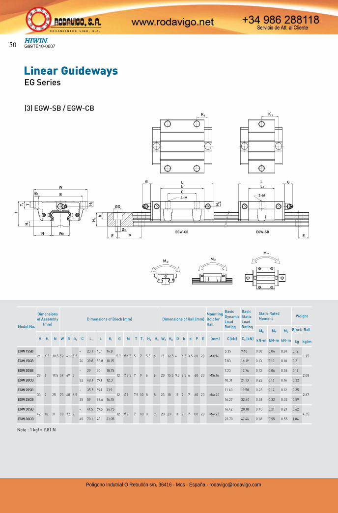
(3) EGW-SB / EGW-CB
Note : 1 kgf = 9.81 N
Model No.
Dimensions
of Assembly
(mm)
Dimensions of Block (mm) Dimensions of Rail (mm)
Mounting
Bolt for
Rail
Basic
Dynamic
Load
Rating
Basic
Static
Load
Rating
Static Rated
MomentWeight
MR
kN-m
MP
kN-m
MY
kN-m
Block
kg
Rail
kg/mH H1 N W B B1 C L1 L K1 G M T T1 H2 H3 WR HR D h d P E (mm) C(kN) C0 (kN)
EGW 15SB
24 4.5 18.5 52 41 5.5
- 23.1 40.1 14.8
5.7 4.5 5 7 5.5 6 15 12.5 6 4.5 3.5 60 20 M3x16
5.35 9.40 0.08 0.04 0.04 0.12
1.25
EGW 15CB 26 39.8 56.8 10.15 7.83 16.19 0.13 0.10 0.10 0.21
EGW 20SB
28 6 19.5 59 49 5
- 29 50 18.75
12 5.5 7 9 6 6 20 15.5 9.5 8.5 6 60 20 M5x16
7.23 12.74 0.13 0.06 0.06 0.19
2.08
EGW 20CB 32 48.1 69.1 12.3 10.31 21.13 0.22 0.16 0.16 0.32
EGW 25SB
33 7 25 73 60 6.5
- 35.5 59.1 21.9
12 7 7.5 10 8 8 23 18 11 9 7 60 20 M6x20
11.40 19.50 0.23 0.12 0.12 0.35
2.67
EGW 25CB 35 59 82.6 16.15 16.27 32.40 0.38 0.32 0.32 0.59
EGW 30SB
42 10 31 90 72 9
- 41.5 69.5 26.75
12 9 7 10 8 9 28 23 11 9 7 80 20 M6x25
16.42 28.10 0.40 0.21 0.21 0.62
4.35
EGW 30CB 40 70.1 98.1 21.05 23.70 47.46 0.68 0.55 0.55 1.04
WN R
T 1
1
H
W
B
TH
1
B
E P
ØD
h
HR
H2
G
ØdEGW-CB
L
4-M
C
1L
H3
1K
EGW-SBE
GL
2-M
1L
K 1
P
YM
MRM
G99TE10-060750
Polígono Indutrial O Rebullón s/n. 36416 - Mos - España - [email protected]
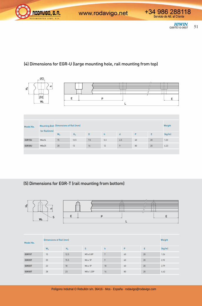
(4) Dimensions for EGR-U (large mounting hole, rail mounting from top)
Model No.Dimensions of Rail (mm) Weight
WR HR S h P E (kg/m)
EGR15T 15 12.5 M5 x 0.8P 7 60 20 1.26
EGR20T 20 15.5 M6 x 1P 9 60 20 2.15
EGR25T 23 18 M6 x 1P 10 60 20 2.79
EGR30T 28 23 M8 x 1.25P 14 80 20 4.42
(5) Dimensions for EGR-T (rail mounting from bottom)
Model No. Mounting Bolt
for Rail(mm)
Dimensions of Rail (mm) Weight
WR HR D h d P E (kg/m)
EGR15U M4x16 15 12.5 7.5 5.3 4.5 60 20 1.23
EGR30U M8x25 28 13 14 12 9 80 20 4.23
D
d
LWR
HR
h
E P E
LWR
S
HR
h
E P E
G99TE10-0607 51
Polígono Indutrial O Rebullón s/n. 36416 - Mos - España - [email protected]
Linear GuidewaysMG Series
2-3 MG Series - Miniature Linear Guideway
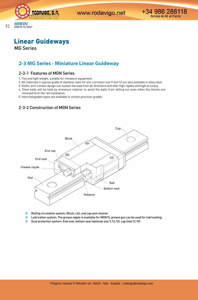
2-3-1 Features of MGN Series1. Tiny and light weight, suitable for miniature equipment.2. All materials in special grade of stainless steel for anti-corrosion size 9 and 12 are also available in alloy steel.3. Gothic arch contact design can sustain the load from all directions and offer high rigidity and high accuracy.4. Steel balls will be held by miniature retainer to avoid the balls from falling out even when the blocks are
removed form the rail installation.5. Interchangeable types are available in certain precision grades.
2-3-2 Construction of MGN Series
End seal
Ball
Grease nipple
End cap
Block
Rail
Cap
Retainer
Bottom seal
¢ Rolling circulation system: Block, rail, end cap and retainer
¢ Lubrication system: The grease nipple is available for MGN15, grease gun can be used for lubricanting.
¢ Dust protection system: End seal, bottom seal (optional size 9,12,15), cap (size12,15)
G99TE10-060752
Polígono Indutrial O Rebullón s/n. 36416 - Mos - España - [email protected]
2-3-5 ApplicationMGN/MGW series can be used in many fields, such as semiconductor equipment, PCB assembly equipment, medical equipment, robotics, measuring equipment, office automation equipment, and other miniature sliding mechinery.
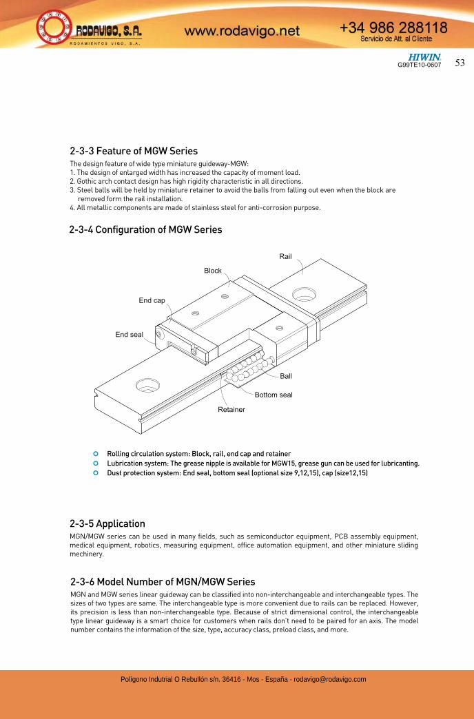
2-3-4 Configuration of MGW Series
Rail
Block
End cap
End seal
Retainer
Ball
Bottom seal
2-3-3 Feature of MGW SeriesThe design feature of wide type miniature guideway-MGW:1. The design of enlarged width has increased the capacity of moment load.2. Gothic arch contact design has high rigidity characteristic in all directions.3. Steel balls will be held by miniature retainer to avoid the balls from falling out even when the block are
removed form the rail installation.4. All metallic components are made of stainless steel for anti-corrosion purpose.
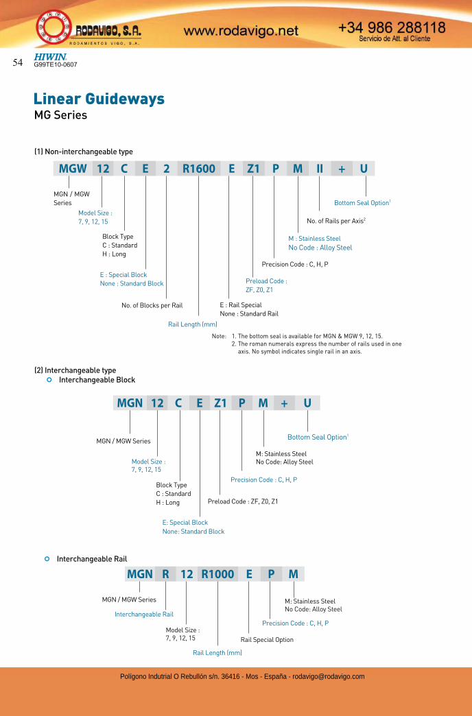
2-3-6 Model Number of MGN/MGW SeriesMGN and MGW series linear guideway can be classified into non-interchangeable and interchangeable types. The sizes of two types are same. The interchangeable type is more convenient due to rails can be replaced. However, its precision is less than non-interchangeable type. Because of strict dimensional control, the interchangeable type linear guideway is a smart choice for customers when rails don’t need to be paired for an axis. The model number contains the information of the size, type, accuracy class, preload class, and more.
¢ Rolling circulation system: Block, rail, end cap and retainer
¢ Lubrication system: The grease nipple is available for MGW15, grease gun can be used for lubricanting.
¢ Dust protection system: End seal, bottom seal (optional size 9,12,15), cap (size12,15)
G99TE10-0607 53
Polígono Indutrial O Rebullón s/n. 36416 - Mos - España - [email protected]
Linear GuidewaysMG Series
Note: 1. The bottom seal is available for MGN & MGW 9, 12, 15. 2. The roman numerals express the number of rails used in one
axis. No symbol indicates single rail in an axis.
MGN / MGW
Series
Block Type
C : Standard
H : Long
Model Size :
7, 9, 12, 15
No. of Blocks per Rail
Rail Length (mm)
E : Rail Special
None : Standard Rail
M : Stainless Steel
No Code : Alloy Steel
Preload Code :
ZF, Z0, Z1
Precision Code : C, H, P
No. of Rails per Axis2
Bottom Seal Option1
MGN / MGW Series
Preload Code : ZF, Z0, Z1
Rail Special Option
Model Size : 7, 9, 12, 15
Block Type
C : Standard
H : Long
M: Stainless SteelNo Code: Alloy Steel
Bottom Seal Option1
(1) Non-interchangeable type
(2) Interchangeable type ¢ Interchangeable Block
¢ Interchangeable Rail
E: Special Block
None: Standard Block
Precision Code : C, H, P
Rail Length (mm)
Precision Code : C, H, P
Interchangeable Rail
MGN 12 C E Z1 P M + U
MGN R 12 R1000 E P M
E : Special Block
None : Standard Block
MGW 12 C E 2 R1600 E Z1 P M II + U
MGN / MGW Series
Model Size : 7, 9, 12, 15
M: Stainless SteelNo Code: Alloy Steel
G99TE10-060754
Polígono Indutrial O Rebullón s/n. 36416 - Mos - España - [email protected]
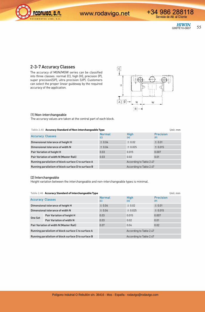
(1) Non-interchangeableThe accuracy values are taken at the central part of each block.
(2) InterchangeableHeight variation between the interchangeable and non-interchangeable types is minimal.
Table 2.45 Accuracy Standard of Non-interchangeable Type Unit: mm
Accuracy ClassesNormal High Precision(C) (H) (P)
Dimensional tolerance of height H 0.04 0.02 0.01
Dimensional tolerance of width N 0.04 0.025 0.015
Pair Variation of height H 0.03 0.015 0.007
Pair Variation of width N (Master Rail) 0.03 0.02 0.01
Running parallelism of block surface C to surface A According to Table 2.47
Running parallelism of block surface D to surface B According to Table 2.47
Table 2.46 Accuracy Standard of Interchangeable Type Unit: mm
Accuracy ClassesNormal High Precision(C) (H) (P)
Dimensional tolerance of height H 0.04 0.02 0.01
Dimensional tolerance of width N 0.04 0.025 0.015
One SetPair Variation of height H 0.03 0.015 0.007
Pair Variation of width N 0.03 0.02 0.01
Pair Variation of width N (Master Rail) 0.07 0.04 0.02
Running parallelism of block surface C to surface A According to Table 2.47
Running parallelism of block surface D to surface B According to Table 2.47
2-3-7 Accuracy ClassesThe accuracy of MGN/MGW series can be classified into three classes: normal (C), high (H), precision (P), super precision(SP), ultra precision (UP). Customers can select the proper linear guideway by the required accuracy of the application.
G99TE10-0607 55
Polígono Indutrial O Rebullón s/n. 36416 - Mos - España - [email protected]
Linear GuidewaysMG Series
Class Code Preload Accuracy
Light Clearance ZF Clearance 4~10µm C
Very Light Preload Z0 0 C~P
Light Preload Z1 0.02C C~P
Table 2.47 Accuracy of Running Parallelism
(3) Accuracy of running parallelismThe running parallelism C to A and D to B are related to the rail length.
2-3-8 PreloadMGN/MGW series provide three preload levels for various applications.
Note: C in column preload means basic dynamic load rating.
Table 2.48 Preload Classes
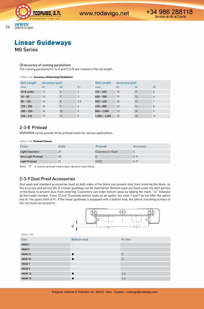
2-3-9 Dust Proof AccessoriesEnd seals and standard accessories fixed on both sides of the block can prevent dust from entering the block, so the accuracy and service life of a linear guideway can be maintained. Bottom seals are fixed under the skirt portion of the block to prevent dust from entering. Customers can order bottom seals by adding the mark “+U” followed by the model number. Sizes 12 and 15 provide bottom seals as an option, but sizes 7 and 9 do not offer the option due to the space limit of H1. If the linear guideway is equipped with a bottom seal, the lateral mounting surface of the rail must not exceed H1.
Rail Length Accuracy (µm) Rail Length Accuracy (µm)
(mm) (C) (H) (P) (mm) (C) (H) (P)
50 & under 12 6 2 315 ~ 400 18 11 6
50 ~ 80 13 7 3 400 ~ 500 19 12 6
80 ~ 125 14 8 3.5 500 ~ 630 20 13 7
125 ~ 200 15 9 4 630 ~ 800 22 14 8
200 ~ 250 16 10 5 800 ~ 1,000 23 16 9
250 ~ 315 17 11 5 1,000 ~ 1,200 25 18 11
Size Bottom seal H1 mm
MGN 7 - -
MGN 9 - -
MGN 12 2
MGN 15 3
MGW 7 - -
MGW 9 - -
MGW 12 2.6
MGW 15 2.6
Table 2.49
G99TE10-060756
Polígono Indutrial O Rebullón s/n. 36416 - Mos - España - [email protected]
SizeBolt size Torque
(kgf-cm)
MGN 7 M2 5.9
MGN 9 M3 19
MGN 12 M3 19
MGN 15 M3 19
MGW 7 M3 19
MGW 9 M3 19
MGW 12 M4 40
MGW 15 M4 40
¢ Tightening torque of bolts for installation
Table 2.51 Tightening Torque
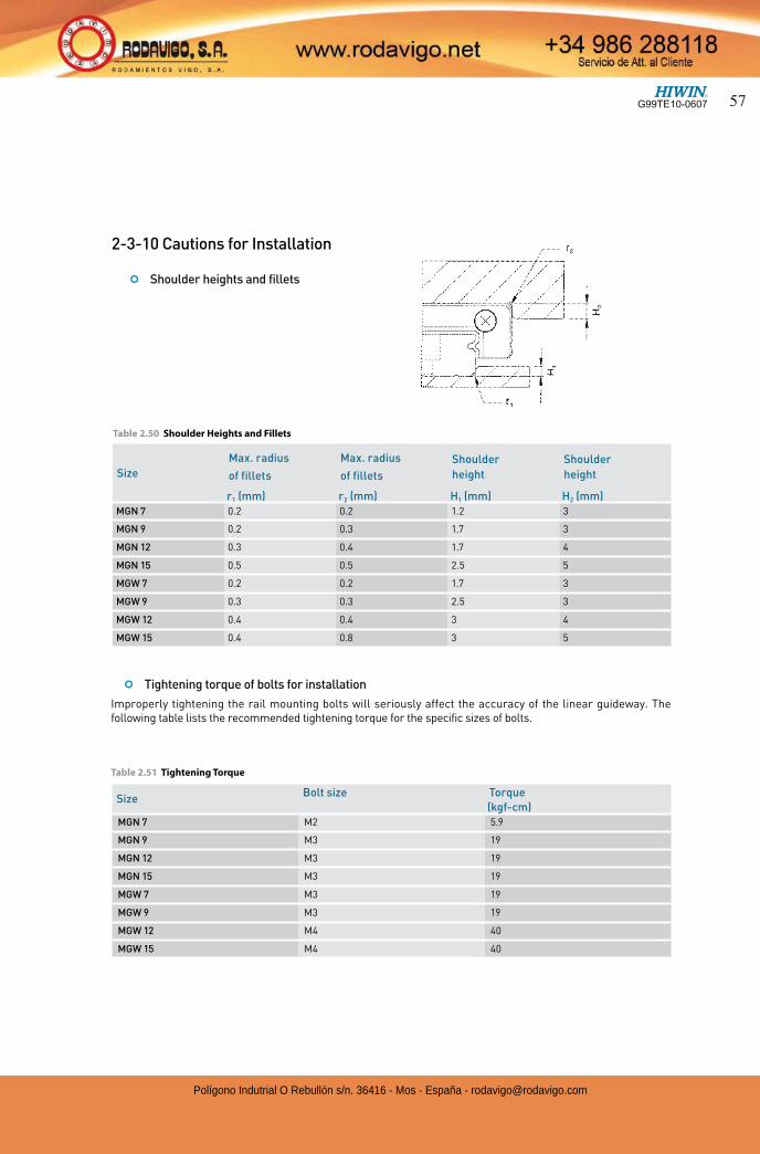
2-3-10 Cautions for Installation
¢ Shoulder heights and fillets
Size
Max. radius
of fillets
Max. radius
of fillets
Shoulder
height
Shoulder
height
r1 (mm) r2 (mm) H1 (mm) H2 (mm)
MGN 7 0.2 0.2 1.2 3
MGN 9 0.2 0.3 1.7 3
MGN 12 0.3 0.4 1.7 4
MGN 15 0.5 0.5 2.5 5
MGW 7 0.2 0.2 1.7 3
MGW 9 0.3 0.3 2.5 3
MGW 12 0.4 0.4 3 4
MGW 15 0.4 0.8 3 5
Table 2.50 Shoulder Heights and Fillets
Improperly tightening the rail mounting bolts will seriously affect the accuracy of the linear guideway. The following table lists the recommended tightening torque for the specific sizes of bolts.
G99TE10-0607 57
Polígono Indutrial O Rebullón s/n. 36416 - Mos - España - [email protected]
Linear GuidewaysMG Series
ItemMGNR MGNR MGNR MGNR MGWR MGWR MGWR MGWR
7M 9M 12M 15M 7M 9M 12M 15M
Standard Length L(n)
40(3) 55(3) 70(3) 70(2) 80(3) 80(3) 110(3) 110(3)
55(4) 75( 4) 95(4) 110(3) 110(4) 110(4) 150(4) 150(4)
70(5) 95(5) 120(5) 150(4) 140(5) 140(5) 190(5) 190(5)
85(6) 115(6) 145(6) 190(5) 170(6) 170(6) 230(6) 230(6)
100(7) 135(7) 170(7) 230(6) 200(7) 200(7) 270(7) 270(7)
130(9) 155(8) 195(8) 270(7) 260(9) 230(8) 310(8) 310(8)
175(9) 220(9) 310(8) 260(9) 350(9) 350(9)
195(10) 245(10) 350(9) 290(10) 390(10) 390(10)
275(14) 270(11) 390(10) 350(14) 430(11) 430(11)
375(19) 320(13) 430(11) 500(19) 510(13) 510(13)
370(15) 470(12) 710(24) 590(15) 590(15)
470(19) 550(14) 860(29) 750(19) 750(19)
570(23) 670(17) 910(23) 910(23)
695(28) 870(22) 1070(27) 1070(27)
Pitch (P) 15 20 25 40 30 30 40 40
Distance to End (Es) 5 7.5 10 15 10 10 15 15
Max. Standard Length 595(40) 995(40) 995(40) 990(25) 590(20) 980(33) 1150(29) 1150(29)
Max. Length 600 1000 1000 1000 1000 1000 1200 1200
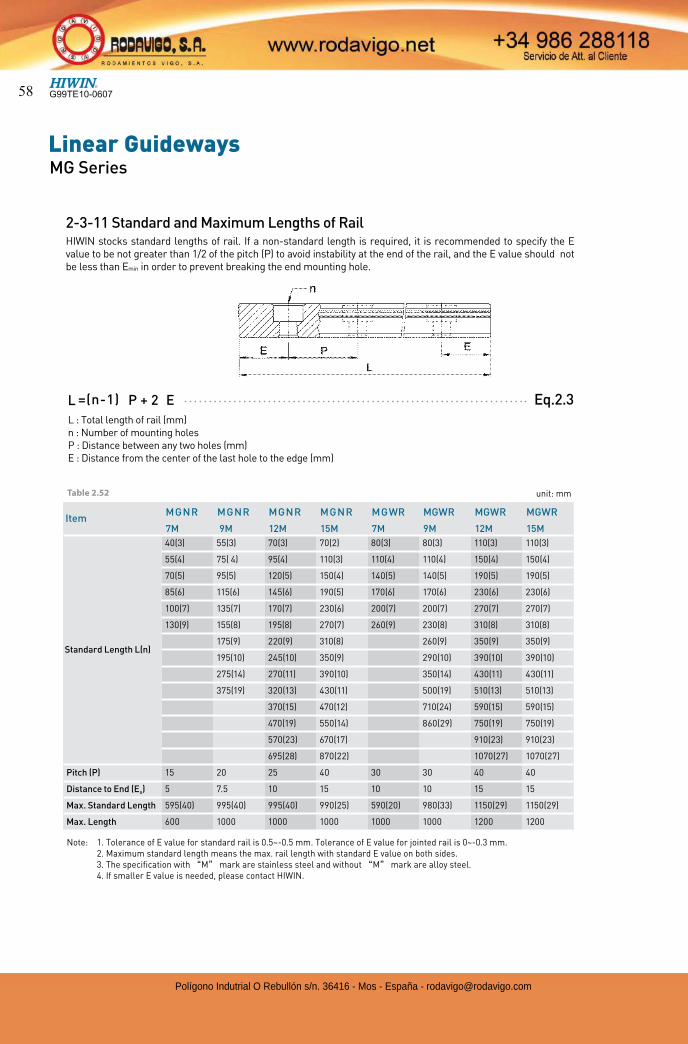
2-3-11 Standard and Maximum Lengths of RailHIWIN stocks standard lengths of rail. If a non-standard length is required, it is recommended to specify the E value to be not greater than 1/2 of the pitch (P) to avoid instability at the end of the rail, and the E value should not be less than Emin in order to prevent breaking the end mounting hole.
Note: 1. Tolerance of E value for standard rail is 0.5~-0.5 mm. Tolerance of E value for jointed rail is 0~-0.3 mm. 2. Maximum standard length means the max. rail length with standard E value on both sides. 3. The specification with M mark are stainless steel and without M mark are alloy steel. 4. If smaller E value is needed, please contact HIWIN.
L : Total length of rail (mm)n : Number of mounting holesP : Distance between any two holes (mm)E : Distance from the center of the last hole to the edge (mm)
Eq.2.3=(n-1)L P + 2 E
unit: mmTable 2.52
G99TE10-060758
Polígono Indutrial O Rebullón s/n. 36416 - Mos - España - [email protected]
l
l
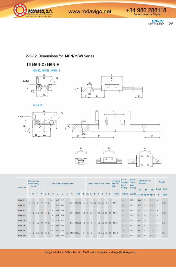
2-3-12 Dimensions for MGN/MGW Series
MGN7, MGN9, MGN12
MGN15
Model No.
Dimensions
of Assembly
(mm)
Dimensions of Block (mm) Dimensions of Rail (mm)
Mounting
Bolt for
Rail
Basic
Dynamic
Load
Rating
Basic
Static
Load
Rating
Static Rated
MomentWeight
MR
kgf-m
MP
kgf-m
MY
kgf-m
Block
g
Rail
kg/mH H1 N W B B1 C L1 L G Gn Mxl H2 WR HR D h d P E (mm) C(kgf) C0 (kgf)
MGN 7C
8 1.5 5 17 12 2.5
8 13.5 22.5
- Ø1.2 M2x2.5 1.5 7 4.8 4.2 2.3 2.4 15 5 M2x6
100 127 0.48 0.29 0.29 10
0.22
MGN 7H 13 21.8 30.8 140 200 0.78 0.49 0.49 15
MGN 9C
10 2 5.5 20 15 2.5
10 18.9 28.9
- Ø1.2 M3x3 1.8 9 6.5 6 3.5 3.5 20 7.5 M3x8
190 260 1.2 0.75 0.75 16
0.38
MGN 9H 16 29.9 39.9 260 410 2 1.9 1.9 26
MGN 12C
13 3 7.5 27 20 3.5
15 21.7 34.7
- Ø1.4 M3x3.5 2.5 12 8 6 4.5 3.5 25 10 M3x8
290 400 2.6 1.4 1.4 34
0.65
MGN 12H 20 32.4 45.4 380 600 3.9 3.7 3.7 54
MGN 15C
16 4 8.5 32 25 3.5
20 26.7 42.1
4.5 CN3S M3x4 3 15 10 6 4.5 3.5 40 15 M3x10
470 570 4.6 2.2 2.2 59
1.06
MGN 15H 25 43.4 58.8 650 930 7.5 5.9 5.9 92
(1) MGN-C / MGN-H
G99TE10-0607 59
Polígono Indutrial O Rebullón s/n. 36416 - Mos - España - [email protected]
Linear GuidewaysMG Series
l
l
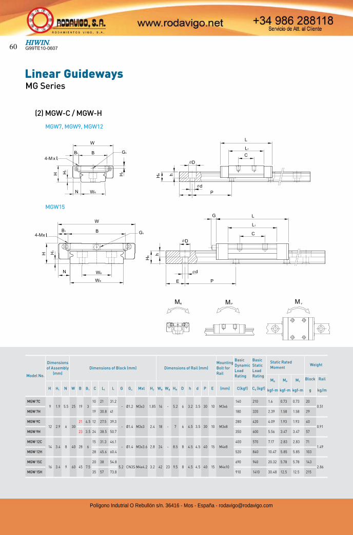
MGW7, MGW9, MGW12
(2) MGW-C / MGW-H
Model No.
Dimensions
of Assembly
(mm)
Dimensions of Block (mm) Dimensions of Rail (mm)
Mounting
Bolt for
Rail
Basic
Dynamic
Load
Rating
Basic
Static
Load
Rating
Static Rated
MomentWeight
MR
kgf-m
MP
kgf-m
MY
kgf-m
Block
g
Rail
kg/mH H1 N W B B1 C L1 L G Gn Mxl H2 WR WB HR D h d P E (mm) C(kgf) C0 (kgf)
MGW 7C
9 1.9 5.5 25 19 3
10 21 31.2
- Ø1.2 M3x3 1.85 14 - 5.2 6 3.2 3.5 30 10 M3x6
140 210 1.6 0.73 0.73 20
0.51
MGW 7H 19 30.8 41 180 320 2.39 1.58 1.58 29
MGW 9C
12 2.9 6 30
21 4.5 12 27.5 39.3
- Ø1.4 M3x3 2.4 18 - 7 6 4.5 3.5 30 10 M3x8
280 420 4.09 1.93 1.93 40
0.91
MGW 9H 23 3.5 24 38.5 50.7 350 600 5.56 3.47 3.47 57
MGW 12C
14 3.4 8 40 28 6
15 31.3 46.1
- Ø1.4 M3x3.6 2.8 24 - 8.5 8 4.5 4.5 40 15 M4x8
400 570 7.17 2.83 2.83 71
1.49
MGW 12H 28 45.6 60.4 520 840 10.47 5.85 5.85 103
MGW 15C
16 3.4 9 60 45 7.5
20 38 54.8
5.2 CN3S M4x4.2 3.2 42 23 9.5 8 4.5 4.5 40 15 M4x10
690 940 20.32 5.78 5.78 143
2.86
MGW 15H 35 57 73.8 910 1410 30.48 12.5 12.5 215
MGW15
G99TE10-060760
Polígono Indutrial O Rebullón s/n. 36416 - Mos - España - [email protected]
2-4 RG Series – High Rigidity Roller Type Linear Guideway
2-4-1 Advantages and features
The new RG series from Hiwin features a roller as the rolling element instead of steel balls. The roller series offers super high rigidity and very high load capacities. The RG series is designed with a 45-degree angle of contact. Elastic deformation of the linear contact surface, during load, is greatly reduced thereby offering greater rigidity and higher load capacities in all 4 load directions.The RG series linear guideway offers high performance for high-precision manufacturing and achieving longer service life.
(1) Optimal designFEM analysis was performed to determine the optimal structure of the block and the rail. The unique design of the circulation path allows the RG series linear guideway to offer smoother linear motion.
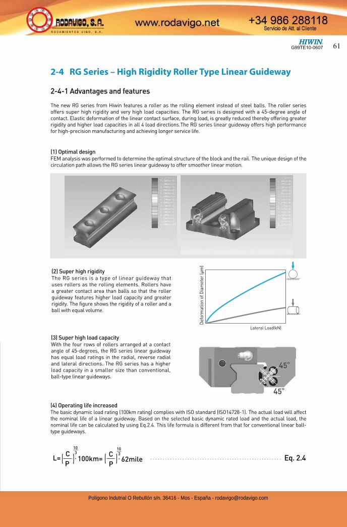
(2) Super high rigidityThe RG series is a type of linear guideway that uses rollers as the rolling elements. Rollers have a greater contact area than balls so that the roller guideway features higher load capacity and greater rigidity. The figure shows the rigidity of a roller and a ball with equal volume.
Lateral Load(kN)
Def
orm
atio
n o
f D
iam
eter
(µ
m)
(3) Super high load capacityWith the four rows of rollers arranged at a contact angle of 45-degrees, the RG series linear guideway has equal load ratings in the radial, reverse radial and lateral directions. The RG series has a higher load capacity in a smaller size than conventional, ball-type linear guideways.
(4) Operating life increasedThe basic dynamic load rating (100km rating) complies with ISO standard (ISO14728-1). The actual load will affect the nominal life of a linear guideway. Based on the selected basic dynamic rated load and the actual load, the nominal life can be calculated by using Eq.2.4. This life formula is different from that for conventional linear ball-type guideways.
L= C
P• 100km= • 62mile
C
P( ( ))3
10
310
Eq. 2.4
G99TE10-0607 61
Polígono Indutrial O Rebullón s/n. 36416 - Mos - España - [email protected]
Linear GuidewaysRG Series
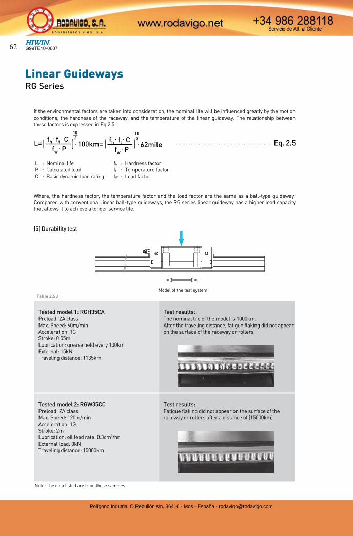
Model of the test system
Tested model 1: RGH35CAPreload: ZA classMax. Speed: 60m/minAcceleration: 1GStroke: 0.55mLubrication: grease held every 100kmExternal: 15kNTraveling distance: 1135km
Test results:The nominal life of the model is 1000km. After the traveling distance, fatigue flaking did not appear on the surface of the raceway or rollers.
Tested model 2: RGW35CCPreload: ZA classMax. Speed: 120m/minAcceleration: 1GStroke: 2mLubrication: oil feed rate: 0.3cm3/hrExternal load: 0kNTraveling distance: 15000km
Test results:Fatigue flaking did not appear on the surface of the raceway or rollers after a distance of (15000km).
Note: The data listed are from these samples.
Table 2.53
If the environmental factors are taken into consideration, the nominal life will be influenced greatly by the motion conditions, the hardness of the raceway, and the temperature of the linear guideway. The relationship between these factors is expressed in Eq.2.5.
Where, the hardness factor, the temperature factor and the load factor are the same as a ball-type guideway.Compared with conventional linear ball-type guideways, the RG series linear guideway has a higher load capacity that allows it to achieve a longer service life.
(5) Durability test
L=fh
• ft• C
fw• P
fh• ft
• C
fw• P
• 100km= • 62mile( ( ))3
10
310
Eq. 2.5
L : Nominal lifeP : Calculated loadC : Basic dynamic load rating
fh : Hardness factorft : Temperature factorfW : Load factor
G99TE10-060762
Polígono Indutrial O Rebullón s/n. 36416 - Mos - España - [email protected]
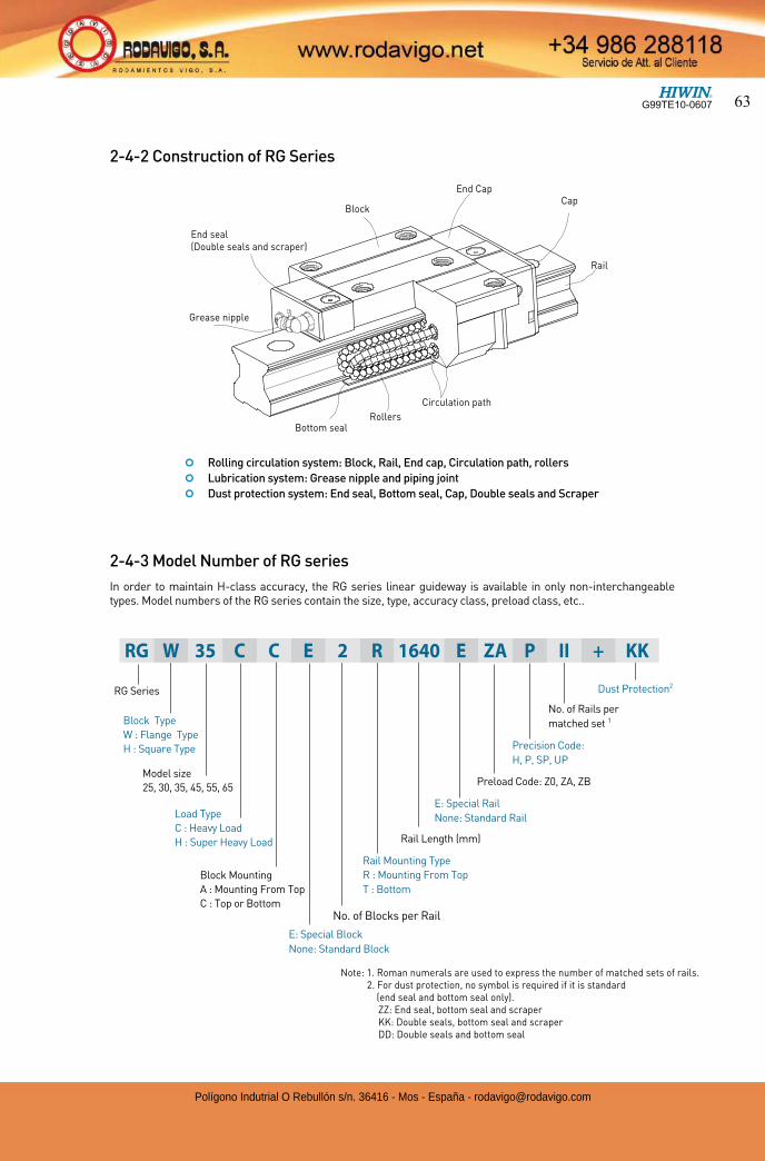
2-4-2 Construction of RG Series
Bottom seal
End Cap
Block
End seal(Double seals and scraper)
Grease nipple
Cap
Rail
Rollers
Circulation path
¢ Rolling circulation system: Block, Rail, End cap, Circulation path, rollers
¢ Lubrication system: Grease nipple and piping joint
¢ Dust protection system: End seal, Bottom seal, Cap, Double seals and Scraper
2-4-3 Model Number of RG series
In order to maintain H-class accuracy, the RG series linear guideway is available in only non-interchangeable types. Model numbers of the RG series contain the size, type, accuracy class, preload class, etc..
RG Series
Block Type
W : Flange Type
H : Square Type
E: Special Block
None: Standard Block
No. of Blocks per Rail
Rail Length (mm)
E: Special Rail
None: Standard Rail
Rail Mounting Type
R : Mounting From Top
T : Bottom
Preload Code: Z0, ZA, ZB
Precision Code:
H, P, SP, UP
No. of Rails per
matched set 1
Dust Protection2
RG W 35 C C E 2 R 1640 E ZA P II + KK
Block Mounting
A : Mounting From Top
C : Top or Bottom
Note: 1. Roman numerals are used to express the number of matched sets of rails. 2. For dust protection, no symbol is required if it is standard
(end seal and bottom seal only). ZZ: End seal, bottom seal and scraper KK: Double seals, bottom seal and scraper DD: Double seals and bottom seal
Model size
25, 30, 35, 45, 55, 65
Load Type
C : Heavy Load
H : Super Heavy Load
G99TE10-0607 63
Polígono Indutrial O Rebullón s/n. 36416 - Mos - España - [email protected]
Linear GuidewaysRG Series
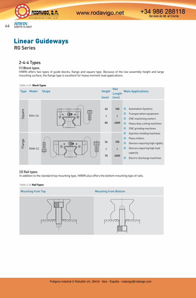
2-4-4 Types(1) Block typesHIWIN offers two types of guide blocks, flange and square type. Because of the low assembly height and large mounting surface, the flange type is excellent for heavy moment load applications.
Type Model Shape HeightRail
LengthMain Applications
(mm) (mm)
RGH-CA
40
i
80
100
i
4000
¢ Automation Systems
¢ Transportation equipment
¢ CNC machining centers
¢ Heavy duty cutting machines
¢ CNC grinding machines
¢ Injection molding machines
¢ Plano millers
¢ Devices requiring high rigidity
¢ Devices requiring high load
capacity
¢ Electric discharge machines
RGW-CC
36
i
70
100
i
4000
Sq
uar
e F
lan
ge
(2) Rail typesIn addition to the standard top mounting type, HIWIN also offers the bottom mounting type of rails.
Table 2.55 Rail Types
Mounting from Top Mounting from Bottom
Table 2.54 Block Types
G99TE10-060764
Polígono Indutrial O Rebullón s/n. 36416 - Mos - España - [email protected]
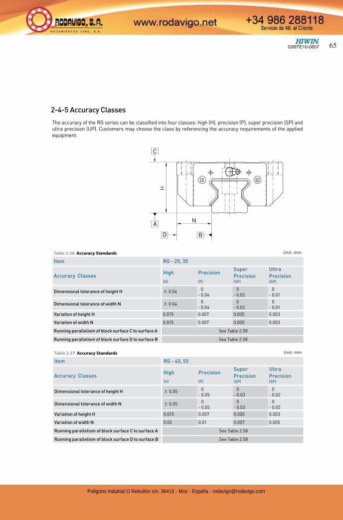
The accuracy of the RG series can be classified into four classes: high (H), precision (P), super precision (SP) and ultra precision (UP). Customers may choose the class by referencing the accuracy requirements of the applied equipment.
Table 2.56 Accuracy Standards Unit: mm
Item RG - 25, 35
Accuracy ClassesHigh Precision
Super
Precision
Ultra
Precision(H) (P) (SP) (SP)
Dimensional tolerance of height H 0.04 0- 0.04
0- 0.02
0- 0.01
Dimensional tolerance of width N 0.04 0- 0.04
0- 0.02
0- 0.01
Variation of height H 0.015 0.007 0.005 0.003
Variation of width N 0.015 0.007 0.005 0.003
Running parallelism of block surface C to surface A See Table 2.58
Running parallelism of block surface D to surface B See Table 2.58
2-4-5 Accuracy Classes
N
D B
C
H
A
Table 2.57 Accuracy Standards Unit: mm
Item RG - 45, 55
Accuracy ClassesHigh Precision
Super
Precision
Ultra
Precision(H) (P) (SP) (SP)
Dimensional tolerance of height H 0.05 0- 0.05
0- 0.03
0- 0.02
Dimensional tolerance of width N 0.05 0- 0.05
0- 0.03
0- 0.02
Variation of height H 0.015 0.007 0.005 0.003
Variation of width N 0.02 0.01 0.007 0.005
Running parallelism of block surface C to surface A See Table 2.58
Running parallelism of block surface D to surface B See Table 2.58
G99TE10-0607 65
Polígono Indutrial O Rebullón s/n. 36416 - Mos - España - [email protected]

Linear GuidewaysRG Series
2-4-6 PreloadA preload can be applied to each guideway using oversized rollers. Generally, a linear motion guideway has negative clearance between the raceway and rollers to improve stiffness and maintain high precision. The RG series linear guideway offers three standard preloads for various applications and conditions.
The figure shows the relationship between the rigidity, friction and nominal life. A preload no larger than ZA would be recommended for smaller model sizes to avoid over-preload affecting the life of the guideway.
Class Code Preload Condition
Light
PreloadZ0 0.02C~ 0.04C Certain load direction, low impact, low precision required
Medium
PreloadZA 0.07C~0.09C High rigidity required, high precision required
Heavy
PreloadZB 0.12C~ 0.14C Super high rigidity required, with vibration and impact
Rigidity
Friction
Life
ZBZAZ0
Table 2.59
Rail Length (mm) Accuracy (µm)
H P SP UP
~ 100 7 3 2 2
100 ~ 200 9 4 2 2
200 ~ 300 10 5 3 2
300 ~ 500 12 6 3 2
500 ~ 700 13 7 4 2
700 ~ 900 15 8 5 3
900 ~ 1,100 16 9 6 3
1,100 ~ 1,500 18 11 7 4
1,500 ~ 1,900 20 13 8 4
1,900 ~ 2,500 22 15 10 5
2,500 ~ 3,100 25 18 11 6
3,100 ~ 3,600 27 20 14 7
3,600 ~ 4,000 28 21 15 7
Table 2.58 Accuracy of Running Parallelism
G99TE10-060766
Polígono Indutrial O Rebullón s/n. 36416 - Mos - España - [email protected]
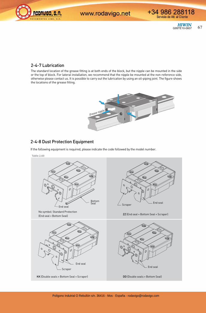
2-4-7 LubricationThe standard location of the grease fitting is at both ends of the block, but the nipple can be mounted in the side or the top of block. For lateral installation, we recommend that the nipple be mounted at the non-reference side, otherwise please contact us. It is possible to carry out the lubrication by using an oil-piping joint. The figure shows the locations of the grease fitting.
Scraper
End seal End seal
Bottom Seal End seal
Scraper
2-4-8 Dust Protection Equipment
If the following equipment is required, please indicate the code followed by the model number.
No symbol: Standard Protection
(End seal + Bottom Seal)
KK (Double seals + Bottom Seal + Scraper) DD (Double seals + Bottom Seal)
ZZ (End seal + Bottom Seal + Scraper)
End seal
Table 2.60
Grease nipple
G99TE10-0607 67
Polígono Indutrial O Rebullón s/n. 36416 - Mos - España - [email protected]
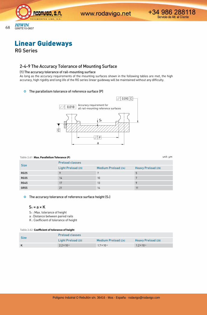
Linear GuidewaysRG Series
SizePreload classes
Light Preload (Z0) Medium Preload (ZA) Heavy Preload (ZB)
RG25 9 7 5
RG35 14 10 7
RG45 17 13 9
GR55 21 14 11
Table 2.62 Coefficient of tolerance of height
2-4-9 The Accuracy Tolerance of Mounting Surface(1) The accuracy tolerance of rail-mounting surfaceAs long as the accuracy requirements of the mounting surfaces shown in the following tables are met, the high accuracy, high rigidity and long life of the RG series linear guideway will be maintained without any difficulty.
unit: µm
¢ The parallelism tolerance of reference surface (P)
P
a
C
S1
0.010 C
0.010Accuracy requirement for all rail-mounting reference surfaces
¢ The accuracy tolerance of reference surface height (S1)
S1 : Max. tolerance of heighta : Distance between paired railsK : Coefficient of tolerance of height
S1 = a × K
Table 2.61 Max. Parallelism Tolerance (P)
SizePreload classes
Light Preload (Z0) Medium Preload (ZA) Heavy Preload (ZB)
K 2.2 10-4 1.7 10-4 1.2 10-4
G99TE10-060768
Polígono Indutrial O Rebullón s/n. 36416 - Mos - España - [email protected]
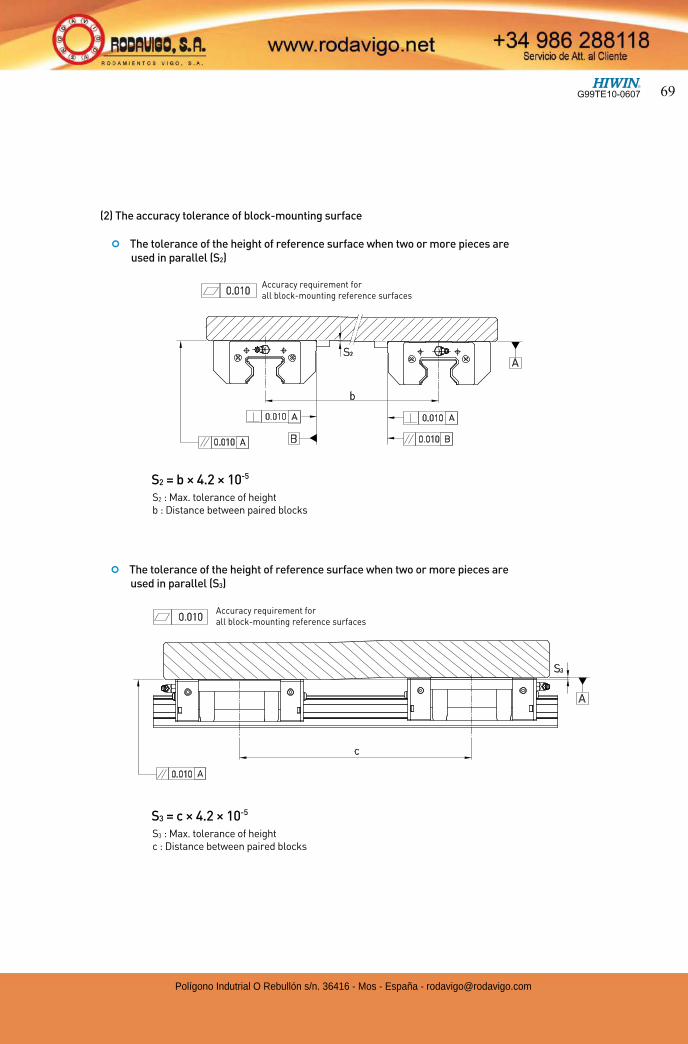
(2) The accuracy tolerance of block-mounting surface
¢ The tolerance of the height of reference surface when two or more pieces are used in parallel (S2)
b
A
0.010
S2
A 0.010 A
B0.010 A 0.010 B
0.010Accuracy requirement for all block-mounting reference surfaces
S2 : Max. tolerance of heightb : Distance between paired blocks
S2 = b × 4.2 × 10⁻⁵
¢ The tolerance of the height of reference surface when two or more pieces are used in parallel (S3)
S3 : Max. tolerance of heightc : Distance between paired blocks
S3 = c × 4.2 × 10⁻⁵
c
S3
0.010
A
0.010 A
Accuracy requirement for all block-mounting reference surfaces
G99TE10-0607 69
Polígono Indutrial O Rebullón s/n. 36416 - Mos - España - [email protected]
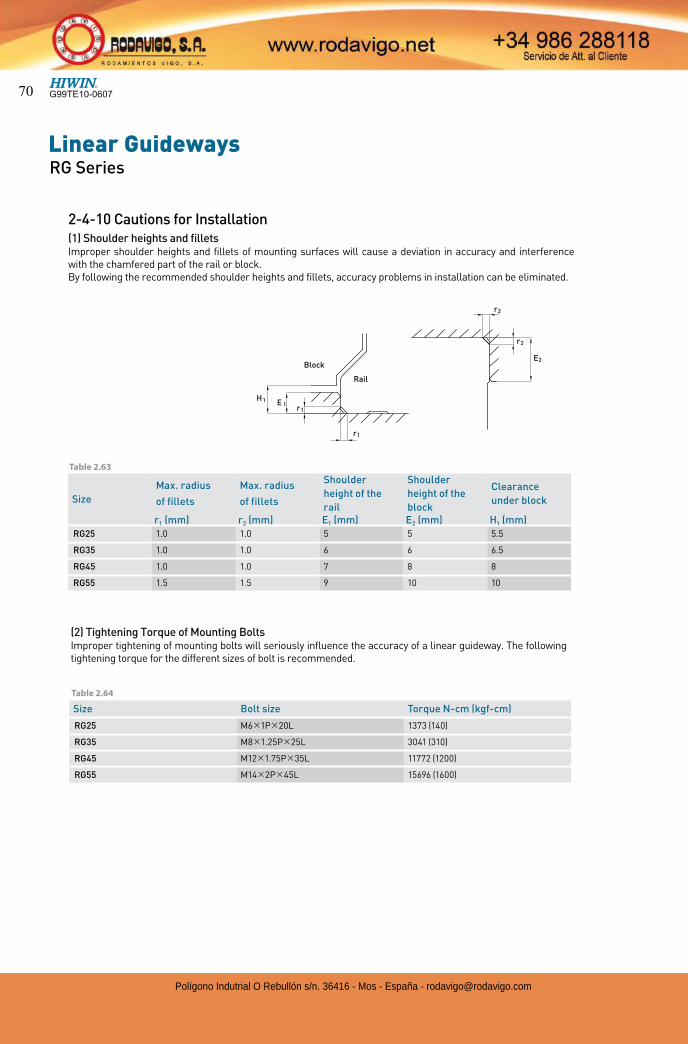
Linear GuidewaysRG Series
Size
Max. radius
of fillets
Max. radius
of fillets
Shoulder
height of the
rail
Shoulder
height of the
block
Clearance
under block
r1 (mm) r2 (mm) E1 (mm) E2 (mm) H1 (mm)
RG25 1.0 1.0 5 5 5.5
RG35 1.0 1.0 6 6 6.5
RG45 1.0 1.0 7 8 8
RG55 1.5 1.5 9 10 10
(2) Tightening Torque of Mounting BoltsImproper tightening of mounting bolts will seriously influence the accuracy of a linear guideway. The following tightening torque for the different sizes of bolt is recommended.
Size Bolt size Torque N-cm (kgf-cm)
RG25 M6 1P 20L 1373 (140)
RG35 M8 1.25P 25L 3041 (310)
RG45 M12 1.75P 35L 11772 (1200)
RG55 M14 2P 45L 15696 (1600)
Table 2.63
Table 2.64
r2
r1
r1
H1
Block
Rail
E 1
r2
E2
2-4-10 Cautions for Installation(1) Shoulder heights and filletsImproper shoulder heights and fillets of mounting surfaces will cause a deviation in accuracy and interference with the chamfered part of the rail or block.By following the recommended shoulder heights and fillets, accuracy problems in installation can be eliminated.
G99TE10-060770
Polígono Indutrial O Rebullón s/n. 36416 - Mos - España - [email protected]
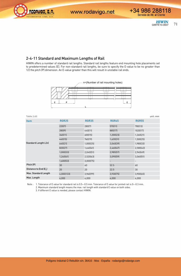
Item RGR25 RGR35 RGR45 RGR55
Standard Length L(n)
220(7) 280(7) 570(11) 780(13)
280(9) 440(11) 885(17) 1020(17)
340(11) 600(15) 1,200(23) 1,260(21)
460(15) 760(19) 1,620(31) 1,500(25)
640(21) 1,000(25) 2,040(39) 1,980(33)
820(27) 1,640(41) 2,460(47) 2,580(43)
1,000(33) 2,040(51) 2,985(57) 2,940(49)
1,240(41) 2,520(63) 3,090(59) 3,060(51)
1,600(53) 3,000(75) - -
Pitch (P) 30 40 52.5 60
Distance to End (Es) 20 20 22.5 30
Max. Standard Length 4,000(133) 3,960(99) 3,930(75) 3,900(65)
Max. Length 4,000 4,000 4,000 4,000
unit: mmTable 2.65
2-4-11 Standard and Maximum Lengths of RailHIWIN offers a number of standard rail lengths. Standard rail lengths feature end mounting hole placements set to predetermined values (E). For non-standard rail lengths, be sure to specify the E-value to be no greater than 1/2 the pitch (P) dimension. An E-value greater than this will result in unstable rail ends.
E P
L
E
n ( )n=(Number of rail mounting holes)
Note : 1. Tolerance of E value for standard rail is 0.5~-0.5 mm. Tolerance of E value for jointed rail is 0~-0.3 mm. 2. Maximum standard length means the max. rail length with standard E value on both sides.
3. If different E value is needed, please contact HIWIN.
G99TE10-0607 71
Polígono Indutrial O Rebullón s/n. 36416 - Mos - España - [email protected]
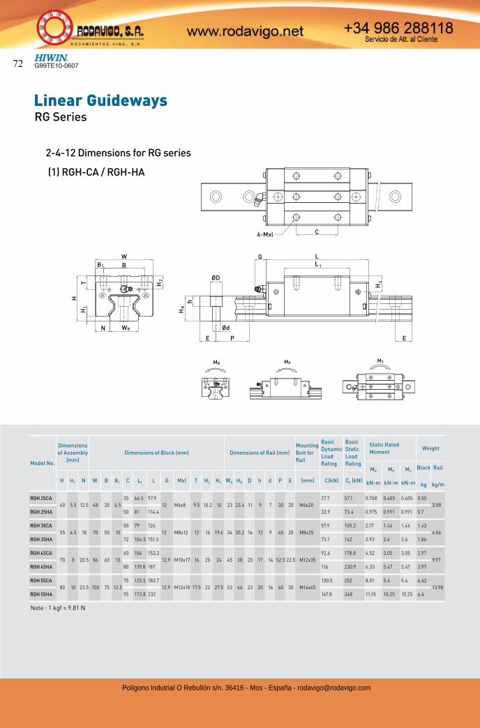
Linear GuidewaysRG Series
2-4-12 Dimensions for RG series
(1) RGH-CA / RGH-HA
W
B
T
H
LG
h
C
N
E P E
B1 L 1
ØD
Ød
H2
HR
H3
H1
6-Mxl
WR
MR MPMY
Model No.
Dimensions
of Assembly
(mm)
Dimensions of Block (mm) Dimensions of Rail (mm)
Mounting
Bolt for
Rail
Basic
Dynamic
Load
Rating
Basic
Static
Load
Rating
Static Rated
MomentWeight
MR
kN-m
MP
kN-m
MY
kN-m
Block
kg
Rail
kg/mH H1 N W B B1 C L1 L G Mxl T H2 H3 WR HR D h d P E (mm) C(kN) C0 (kN)
RGH 25CA
40 5.5 12.5 48 35 6.5
35 64.5 97.9
12 M6x8 9.5 10.2 10 23 23.6 11 9 7 30 20 M6x20
27.7 57.1 0.758 0.605 0.605 0.55
3.08
RGH 25HA 50 81 114.4 33.9 73.4 0.975 0.991 0.991 0.7
RGH 35CA
55 6.5 18 70 50 10
50 79 124
12 M8x12 12 16 19.6 34 30.2 14 12 9 40 20 M8x25
57.9 105.2 2.17 1.44 1.44 1.43
6.06
RGH 35HA 72 106.5 151.5 73.1 142 2.93 2.6 2.6 1.86
RGH 45CA
70 8 20.5 86 60 13
60 106 153.2
12.9 M10x17 16 20 24 45 38 20 17 14 52.5 22.5 M12x35
92.6 178.8 4.52 3.05 3.05 2.97
9.97
RGH 45HA 80 139.8 187 116 230.9 6.33 5.47 5.47 3.97
RGH 55CA
80 10 23.5 100 75 12.5
75 125.5 183.7
12.9 M12x18 17.5 22 27.5 53 44 23 20 16 60 30 M14x45
130.5 252 8.01 5.4 5.4 4.62
13.98
RGH 55HA 95 173.8 232 167.8 348 11.15 10.25 10.25 6.4
Note : 1 kgf = 9.81 N
G99TE10-060772
Polígono Indutrial O Rebullón s/n. 36416 - Mos - España - [email protected]

Model No.
Dimensions
of Assembly
(mm)
Dimensions of Block (mm) Dimensions of Rail (mm)
Mounting
Bolt for
Rail
Basic
Dynamic
Load
Rating
Basic
Static
Load
Rating
Static Rated
MomentWeight
MR
kN-m
MP
kN-m
MY
kN-m
Block
kg
Rail
kg/mH H1 N W B B1 C C1 L1 L G M T T1 H2 H3 WR HR D h d P E (mm) C(kN) C0 (kN)
RGW 25CC
36 5.5 23.5 70 57 6.5 45 40
64.5 97.9
12 M8 9.5 10 6.2 6 23 23.6 11 9 7 30 20 M6x20
27.7 57.1 0.758 0.605 0.605 0.67
3.08
RGW 25HC 81 114.4 33.9 73.4 0.975 0.991 0.991 0.86
RGW 35CC
48 6.5 33 100 82 9 62 52
79 124
12 M10 12 13 9 12.6 34 30.2 14 12 9 40 20 M8x25
57.9 105.2 2.17 1.44 1.44 1.61
6.06
RGW 35HC 106.5 151.5 73.1 142 2.93 2.6 2.6 2.21
RGW 45CC
60 8 37.5 120 100 10 80 60
106 153.2
12.9 M12 14 15 10 14 45 38 20 17 14 52.5 22.5 M12x35
92.6 178.8 4.52 3.05 3.05 3.22
9.97
RGW 45HC 139.8 187 116 230.9 6.33 5.47 5.47 4.41
RGW 55CC
70 10 43.5 140 116 12 95 70
125.5 183.7
12.9 M14 16 17 12 17.5 53 44 23 20 16 60 30 M14x45
130.5 252 8.01 5.4 5.4 5.18
13.98
RGW 55HC 173.8 232 167.8 348 11.15 10.25 10.25 7.34
W
B
T
H
N
B1
H1
WR
H2
T1
C
6-M C1
LG
E P
h
E
L1
H3
ØD
Ød
HR
MR MP
MY
(2) RGW-CC / RGW-HC
Note : 1 kgf = 9.81 N
G99TE10-0607 73
Polígono Indutrial O Rebullón s/n. 36416 - Mos - España - [email protected]
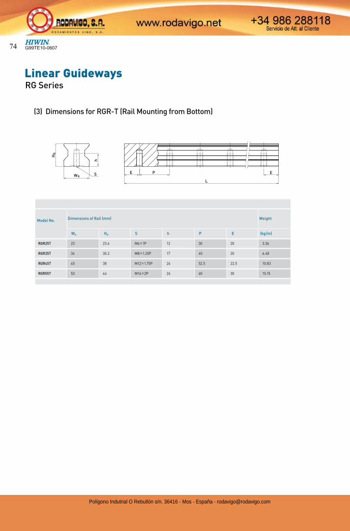
Linear GuidewaysRG Series
E P
L
E
h
HR
WRS
Model No. Dimensions of Rail (mm) Weight
WR HR S h P E (kg/m)
RGR25T 23 23.6 M6 1P 12 30 20 3.36
RGR35T 34 30.2 M8 1.25P 17 40 20 6.48
RGR45T 45 38 M12 1.75P 24 52.5 22.5 10.83
RGR55T 53 44 M14 2P 24 60 30 15.15
(3) Dimensions for RGR-T (Rail Mounting from Bottom)
G99TE10-060774
Polígono Indutrial O Rebullón s/n. 36416 - Mos - España - [email protected]
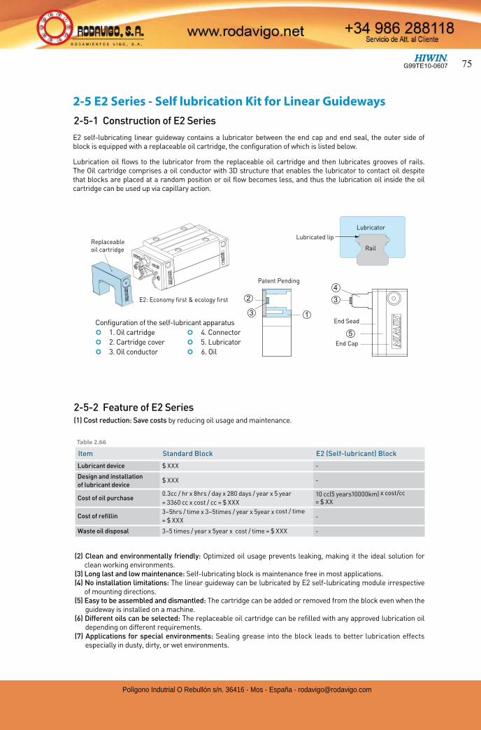
(2) Clean and environmentally friendly: Optimized oil usage prevents leaking, making it the ideal solution for clean working environments.
(3) Long last and low maintenance: Self-lubricating block is maintenance free in most applications.(4) No installation limitations: The linear guideway can be lubricated by E2 self-lubricating module irrespective
of mounting directions.(5) Easy to be assembled and dismantled: The cartridge can be added or removed from the block even when the
guideway is installed on a machine.(6) Different oils can be selected: The replaceable oil cartridge can be refilled with any approved lubrication oil
depending on different requirements.(7) Applications for special environments: Sealing grease into the block leads to better lubrication effects
especially in dusty, dirty, or wet environments.
2-5 E2 Series - Self lubrication Kit for Linear Guideways
E2 self-lubricating linear guideway contains a lubricator between the end cap and end seal, the outer side of block is equipped with a replaceable oil cartridge, the configuration of which is listed below.
Lubrication oil flows to the lubricator from the replaceable oil cartridge and then lubricates grooves of rails. The Oil cartridge comprises a oil conductor with 3D structure that enables the lubricator to contact oil despite that blocks are placed at a random position or oil flow becomes less, and thus the lubrication oil inside the oil cartridge can be used up via capillary action.
Patent Pending
13
2
4
3
5
End Sead
End Cap
Lubricated lip
Rail
Lubricator
Item Standard Block E2 (Self-lubricant) Block
Lubricant device $ XXX -
Design and installation
of lubricant device$ XXX -
Cost of oil purchase 0.3cc / hr x 8hrs / day x 280 days / year x 5 year
= 3360 cc x cost / cc = $ XXX 10 cc(5 years10000km) x cost/cc
= $ XX
Cost of refillin3~5hrs / time x 3~5times / year x 5year x cost / time
= $ XXX -
Waste oil disposal 3~5 times / year x 5year x cost / time = $ XXX -
E2: Economy first & ecology first
Replaceableoil cartridge
2-5-1 Construction of E2 Series
Configuration of the self-lubricant apparatus
¢ 1. Oil cartridge ¢ 4. Connector
¢ 2. Cartridge cover ¢ 5. Lubricator
¢ 3. Oil conductor ¢ 6. Oil
2-5-2 Feature of E2 Series(1) Cost reduction: Save costs by reducing oil usage and maintenance.
Table 2.66
G99TE10-0607 75
Polígono Indutrial O Rebullón s/n. 36416 - Mos - España - [email protected]
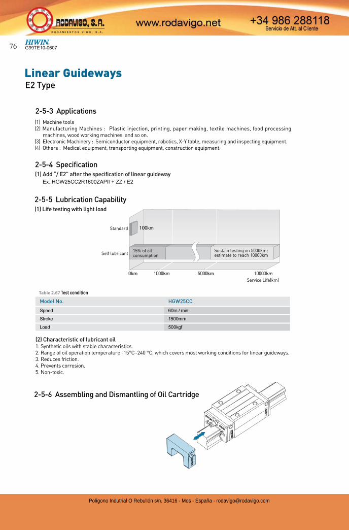
Linear GuidewaysE2 Type
(2) Characteristic of lubricant oil1. Synthetic oils with stable characteristics.2. Range of oil operation temperature -15°C~240 °C, which covers most working conditions for linear guideways.3. Reduces friction.4. Prevents corrosion.5. Non-toxic.
2-5-4 Specification(1) Add “/ E2” after the specification of linear guideway
Ex. HGW25CC2R1600ZAPII + ZZ / E2
(1) Machine tools(2) Manufacturing Machines : Plastic injection, printing, paper making, textile machines, food processing
machines, wood working machines, and so on. (3) Electronic Machinery : Semiconductor equipment, robotics, X-Y table, measuring and inspecting equipment.(4) Others : Medical equipment, transporting equipment, construction equipment.
2-5-3 Applications
2-5-5 Lubrication Capability(1) Life testing with light load
Service Life(km)
Standard
Self lubricant
0km 1000km 5000km 10000km
Sustain testing on 5000km; estimate to reach 10000km
15% of oil consumption
Model No. HGW25CC
Speed 60m / min
Stroke 1500mm
Load 500kgf
Table 2.67 Test condition
2-5-6 Assembling and Dismantling of Oil Cartridge
G99TE10-060776
Polígono Indutrial O Rebullón s/n. 36416 - Mos - España - [email protected]
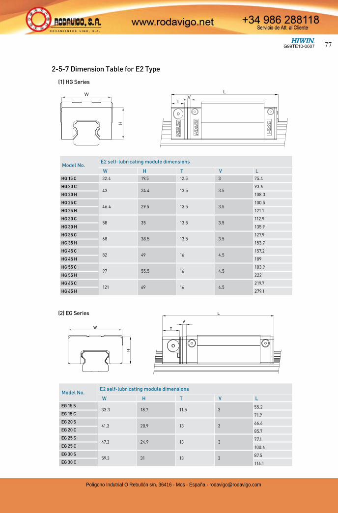
2-5-7 Dimension Table for E2 Type
T
L
V
H
W
Model No.E2 self-lubricating module dimensions
W H T V L
HG 15 C 32.4 19.5 12.5 3 75.4
HG 20 C43 24.4 13.5 3.5
93.6
HG 20 H 108.3
HG 25 C46.4 29.5 13.5 3.5
100.5
HG 25 H 121.1
HG 30 C58 35 13.5 3.5
112.9
HG 30 H 135.9
HG 35 C68 38.5 13.5 3.5
127.9
HG 35 H 153.7
HG 45 C82 49 16 4.5
157.2
HG 45 H 189
HG 55 C97 55.5 16 4.5
183.9
HG 55 H 222
HG 65 C121 69 16 4.5
219.7
HG 65 H 279.1
Model No.E2 self-lubricating module dimensions
W H T V L
EG 15 S33.3 18.7 11.5 3
55.2
EG 15 C 71.9
EG 20 S41.3 20.9 13 3
66.6
EG 20 C 85.7
EG 25 S47.3 24.9 13 3
77.1
EG 25 C 100.6
EG 30 S59.3 31 13 3
87.5
EG 30 C 116.1
(1) HG Series
(2) EG Series
G99TE10-0607 77
Polígono Indutrial O Rebullón s/n. 36416 - Mos - España - [email protected]
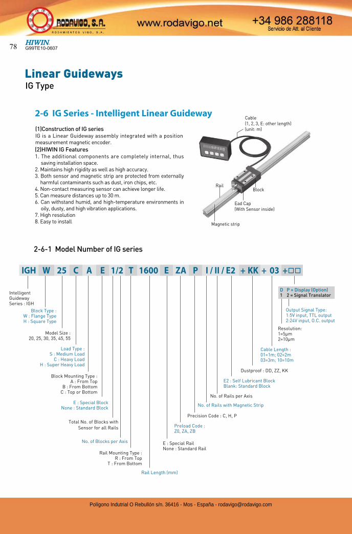
Linear GuidewaysIG Type
(1)Construction of IG seriesIG is a Linear Guideway assembly integrated with a position measurement magnetic encoder.
(2)HIWIN IG Features1. The additional components are completely internal, thus
saving installation space.2. Maintains high rigidity as well as high accuracy.3. Both sensor and magnetic strip are protected from externally
harmful contaminants such as dust, iron chips, etc.4. Non-contact measuring sensor can achieve longer life.5. Can measure distances up to 30 m.6. Can withstand humid, and high-temperature environments in
oily, dusty, and high vibration applications.7. High resolution8. Easy to install
BlockRail
Magnetic strip
Cable(1, 2, 3, E: other length)(unit: m)
Ead Cap(With Sensor inside)
Dustproof : DD, ZZ, KK
E2 : Self Lubricant BlockBlank: Standard Block
Block Type :W : Flange TypeH : Square Type
Model Size :20, 25, 30, 35, 45, 55
Load Type :S : Medium Load
C : Heavy LoadH : Super Heavy Load
Block Mounting Type :A : From Top
B : From BottomC : Top or Bottom
Rail Mounting Type :R : From Top
T : From Bottom
No. of Blocks per Axis
Rail Length (mm)
Preload Code : Z0, ZA, ZB
Precision Code : C, H, P
No. of Rails with Magnetic Strip
No. of Rails per Axis
E : Special RailNone : Standard Rail
Output Signal Type:1:5V input, TTL output2:24V input, O.C. output
Cable Length :01=1m; 02=2m03=3m; 10=10m
Resolution:1=5µm2=10µm
D P = Display (Option)1 2 = Signal TranslatorIntelligent
Guideway Series : IGH
Total No. of Blocks with Sensor for all Rails
E : Special BlockNone : Standard Block
IGH W 25 C A E 1/2 T 1600 E ZA P I / II / E2 + KK + 03 +
2-6-1 Model Number of IG series
2-6 IG Series - Intelligent Linear Guideway
G99TE10-060778
Polígono Indutrial O Rebullón s/n. 36416 - Mos - España - [email protected]
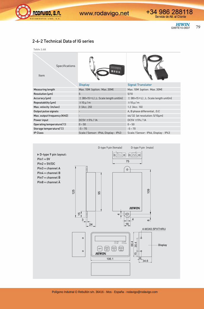
2-6-2 Technical Data of IG series
D-type 9 pin (male)D-type 9 pin (female)
} D-type 9 pin layout:
Pin1 = 0V
Pin2 = 5V/DC
Pin3 = channel A
Pin4 = channel B
Pin7 = channel B
Pin8 = channel A
Display Signal Translator
Measuring length Max. 10M (option: Max. 30M) Max. 10M (option: Max. 30M)
Resolution (µm) 5 5/10
Accuracy (µm) (80+15 L) ,L: Scale length unit(m) (80+15 L) , L: Scale length unit(m)
Repeatability (µm) 10 µ / m 10 µ / m
Max. velocity (m/sec) 3 (Acc. 2G) 1.2 (Acc. 1G)
Output pulse signals - A, B phase differential , O.C
Max. output frequency (KHZ) - 64/ 32 (at resolution: 5/10µm)
Power input DC5V 5% / 1A DC5V 5% / 1A
Operating temperature( ) 0 ~ 50 0 ~ 50
Storage temperature( ) -5 ~ 70 -5 ~ 70
IP Class Scale / Sensor: IP66, Display : IP43 Scale / Sensor: IP66, Display : IP43
Specifications
Item
Table 2.68
Display
G99TE10-0607 79
Polígono Indutrial O Rebullón s/n. 36416 - Mos - España - [email protected]
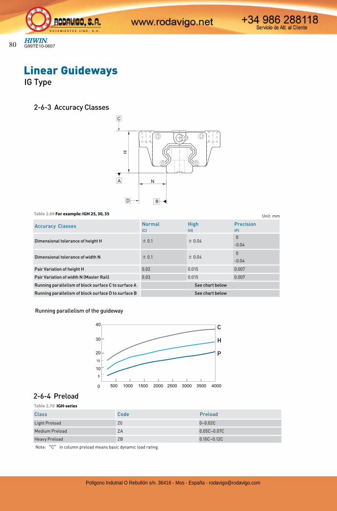
Linear GuidewaysIG Type
Class Code Preload
Light Preload Z0 0~0.02C
Medium Preload ZA 0.05C~0.07C
Heavy Preload ZB 0.10C~0.12C
2-6-3 Accuracy Classes
Running parallelism of the guideway
2-6-4 Preload
Note: C in column preload means basic dynamic load rating.
C
H
P
Unit: mm
Accuracy Classes Normal High Precision(C) (H) (P)
Dimensional tolerance of height H 0.1 0.040
-0.04
Dimensional tolerance of width N 0.1 0.040
-0.04
Pair Variation of height H 0.02 0.015 0.007
Pair Variation of width N (Master Rail) 0.03 0.015 0.007
Running parallelism of block surface C to surface A See chart below
Running parallelism of block surface D to surface B See chart below
Table 2.69 For example: IGH 25, 30, 35
Table 2.70 IGH-series
G99TE10-060780
Polígono Indutrial O Rebullón s/n. 36416 - Mos - España - [email protected]
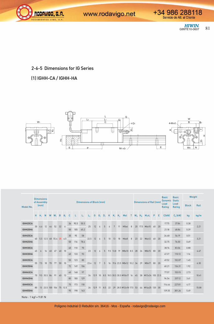
(1) IGHH-CA / IGHH-HA
2-6-5 Dimensions for IG Series
Model No.
Dimensions
of Assembly
(mm)
Dimensions of Block (mm) Dimensions of Rail (mm)
Basic
Dynamic
Load
Rating
Basic
Static
Load
Rating
Weight
Block Rail
H H1 N W W1 B B1 C L L1 L2 G G1 D1 K K1 K2 Mxl T WR HR M1xl1 P E C(kN) C0 (kN) kg kg/m
IGHH20CA
30 4.6 12 44 52 32 6
36 90.5 50.5
25 12 6 5 6 7 11 M5x6 8 20 17.5 M6x10 60 20
17.75 37.84 0.38
2.21
IGHH20HA 50 105 65.2 21.18 48.84 0.39
IGHH25CA
40 5.5 12.5 48 55.4 35 6.5
35 95 58
22.5 12 6 5 10 13 18 M6x8 8 23 22 M6x12 60 20
26.48 56.19 0.51
3.21
IGHH25HA 50 116 78.6 32.75 76.00 0.69
IGHH30CA
45 6 16 60 67 40 10
40 110 70
23 12 6 5 9.5 13.8 19 M8x10 8.5 28 26 M8x15 80 20
38.74 83.06 0.88
4.47
IGHH30HA 60 133 93 47.27 110.13 1.16
IGHH35CA
55 7.5 18 70 77 50 10
50 123 80
23.4 12 7 5 16 19.6 23.5 M8x12 10.2 34 29 M8x17 80 20
49.52 102.87 1.45
6.30
IGHH35HA 72 149 106 60.21 136.31 1.92
IGHH45CA
70 9.5 20.5 86 91 60 13
60 148 97
26 12.9 10 8.5 18.5 30.5 30.5 M10x17 16 45 38 M12x24 105 22.5
77.57 155.93 2.73
10.41
IGHH45HA 80 180 129 94.54 207.12 3.61
IGHH55CA
80 13 23.5 100 106 75 12.5
75 173 118
26 12.9 11 8.5 22 29 28.5 M12x18 17.5 53 44 M14x25 120 30
114.44 227.81 4.17
15.08
IGHH55HA 95 198 143 139.35 301.26 5.49
Note : 1 kgf = 9.81 N
G99TE10-0607 81
Polígono Indutrial O Rebullón s/n. 36416 - Mos - España - [email protected]
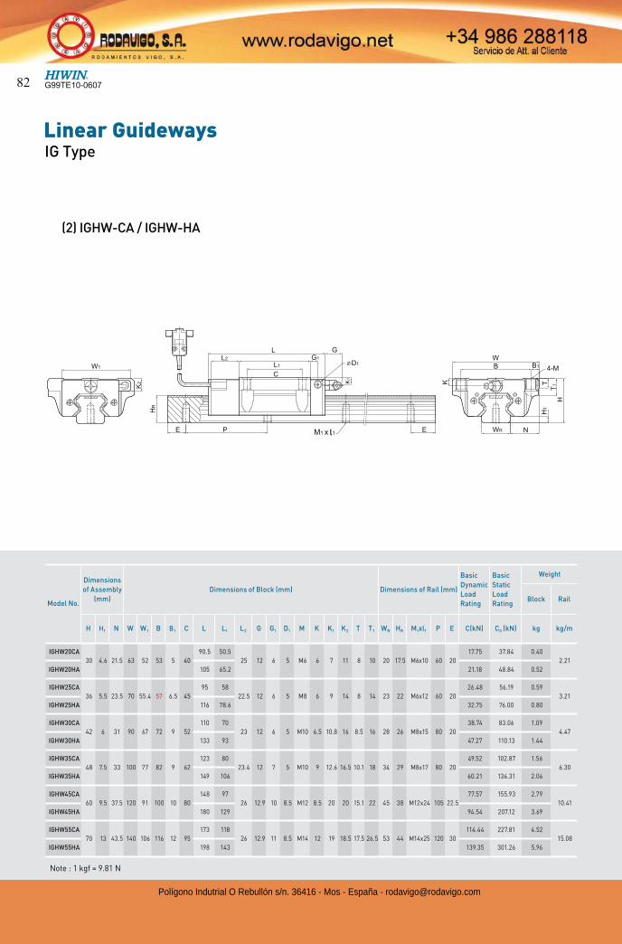
Linear GuidewaysIG Type
(2) IGHW-CA / IGHW-HA
Model No.
Dimensions
of Assembly
(mm)
Dimensions of Block (mm) Dimensions of Rail (mm)
Basic
Dynamic
Load
Rating
Basic
Static
Load
Rating
Weight
Block Rail
H H1 N W W1 B B1 C L L1 L2 G G1 D1 M K K1 K2 T T1 WR HR M1xl1 P E C(kN) C0 (kN) kg kg/m
IGHW20CA
30 4.6 21.5 63 52 53 5 40
90.5 50.5
25 12 6 5 M6 6 7 11 8 10 20 17.5 M6x10 60 20
17.75 37.84 0.40
2.21
IGHW20HA 105 65.2 21.18 48.84 0.52
IGHW25CA
36 5.5 23.5 70 55.4 57 6.5 45
95 58
22.5 12 6 5 M8 6 9 14 8 14 23 22 M6x12 60 20
26.48 56.19 0.59
3.21
IGHW25HA 116 78.6 32.75 76.00 0.80
IGHW30CA
42 6 31 90 67 72 9 52
110 70
23 12 6 5 M10 6.5 10.8 16 8.5 16 28 26 M8x15 80 20
38.74 83.06 1.09
4.47
IGHW30HA 133 93 47.27 110.13 1.44
IGHW35CA
48 7.5 33 100 77 82 9 62
123 80
23.4 12 7 5 M10 9 12.6 16.5 10.1 18 34 29 M8x17 80 20
49.52 102.87 1.56
6.30
IGHW35HA 149 106 60.21 136.31 2.06
IGHW45CA
60 9.5 37.5 120 91 100 10 80
148 97
26 12.9 10 8.5 M12 8.5 20 20 15.1 22 45 38 M12x24 105 22.5
77.57 155.93 2.79
10.41
IGHW45HA 180 129 94.54 207.12 3.69
IGHW55CA
70 13 43.5 140 106 116 12 95
173 118
26 12.9 11 8.5 M14 12 19 18.5 17.5 26.5 53 44 M14x25 120 30
114.44 227.81 4.52
15.08
IGHW55HA 198 143 139.35 301.26 5.96
Note : 1 kgf = 9.81 N
G99TE10-060782
Polígono Indutrial O Rebullón s/n. 36416 - Mos - España - [email protected]
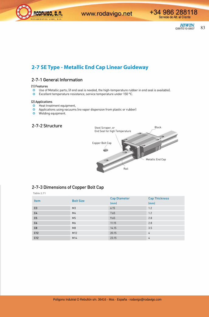
(1) Features ¢ Use of Metallic parts; (if end seal is needed, the high-temperature rubber in end seal is available). ¢ Excellent temperature resistance; service temperature under 150 °C. (2) Applications ¢ Heat treatment equipment, ¢ Applications using vacuums (no vapor dispersion from plastic or rubber) ¢ Welding equipment.
2-7-3 Dimensions of Copper Bolt Cap
2-7 SE Type - Metallic End Cap Linear Guideway
2-7-1 General Information
Item Bolt Size Cap Diameter Cap Thickness
(mm) (mm)
C3 M3 6.15 1.2
C4 M4 7.65 1.2
C5 M5 9.65 2.8
C6 M6 11.15 2.8
C8 M8 14.15 3.5
C12 M12 20.15 4
C12 M14 23.15 4
2-7-2 Structure
Table 2.71
Block
Rail
Steel Scraper, orEnd Seal for high Temperature
Copper Bolt Cap
Metallic End Cap
G99TE10-0607 83
Polígono Indutrial O Rebullón s/n. 36416 - Mos - España - [email protected]
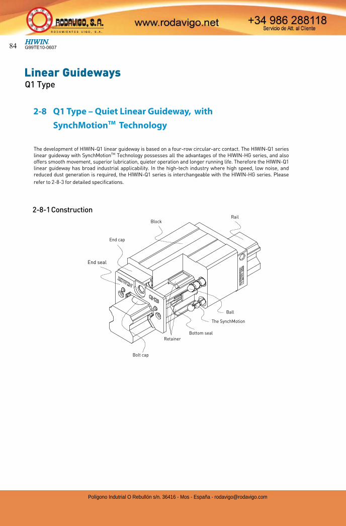
Linear GuidewaysQ1 Type
2-8 Q1 Type – Quiet Linear Guideway, with
SynchMotionTM Technology
Block
End seal
End cap
Rail
Bolt cap
RetainerBottom seal
Ball
The SynchMotion
2-8-1 Construction
The development of HIWIN-Q1 linear guideway is based on a four-row circular-arc contact. The HIWIN-Q1 series linear guideway with SynchMotionTM Technology possesses all the advantages of the HIWIN-HG series, and also offers smooth movement, superior lubrication, quieter operation and longer running life. Therefore the HIWIN-Q1 linear guideway has broad industrial applicability. In the high-tech industry where high speed, low noise, and reduced dust generation is required, the HIWIN-Q1 series is interchangeable with the HIWIN-HG series. Please
refer to 2-8-3 for detailed specifications.
G99TE10-060784
Polígono Indutrial O Rebullón s/n. 36416 - Mos - España - [email protected]
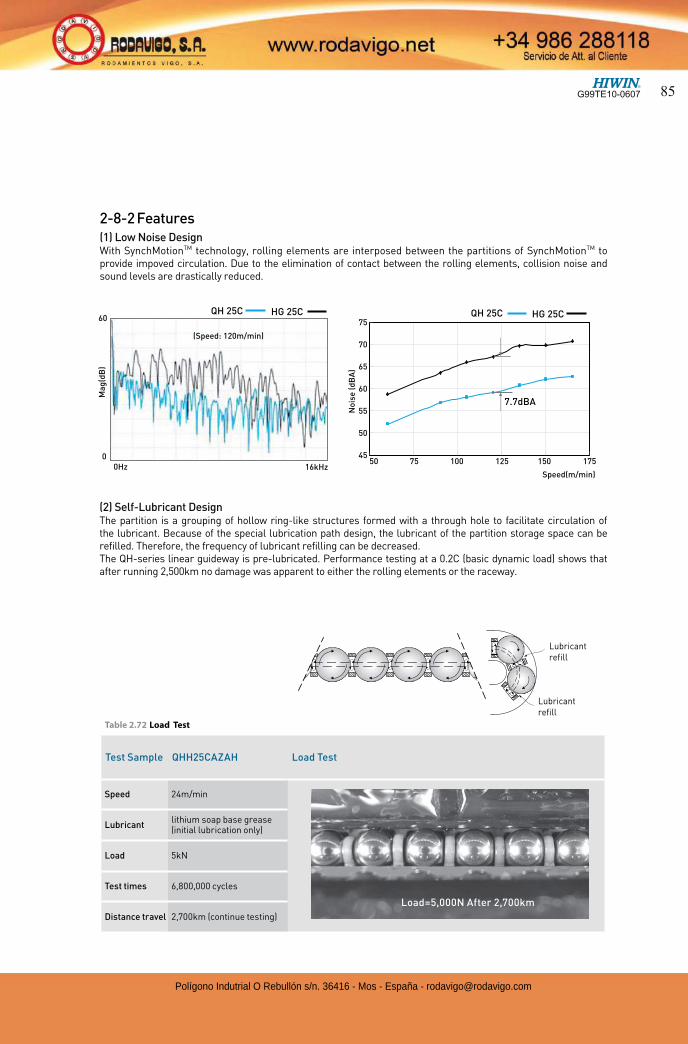
2-8-2 Features(1) Low Noise DesignWith SynchMotionTM technology, rolling elements are interposed between the partitions of SynchMotionTM to provide impoved circulation. Due to the elimination of contact between the rolling elements, collision noise and sound levels are drastically reduced.
Ma
g(d
B)
60
00Hz 16kHz
(Speed: 120m/min)
HG 25CQH 25C
45
50
55
60
65
70
75
50 75 100 125 150 175
Speed(m/min)
No
ise
(d
BA
)
7.7dBA
HG 25CQH 25C
(2) Self-Lubricant DesignThe partition is a grouping of hollow ring-like structures formed with a through hole to facilitate circulation of the lubricant. Because of the special lubrication path design, the lubricant of the partition storage space can be refilled. Therefore, the frequency of lubricant refilling can be decreased.The QH-series linear guideway is pre-lubricated. Performance testing at a 0.2C (basic dynamic load) shows that after running 2,500km no damage was apparent to either the rolling elements or the raceway.
Test Sample QHH25CAZAH Load Test
Speed 24m/min
Lubricantlithium soap base grease (initial lubrication only)
Load 5kN
Test times 6,800,000 cycles
Distance travel 2,700km (continue testing)
Table 2.72 Load Test
Load=5,000N After 2,700km
Lubricant refill
Lubricant refill
G99TE10-0607 85
Polígono Indutrial O Rebullón s/n. 36416 - Mos - España - [email protected]
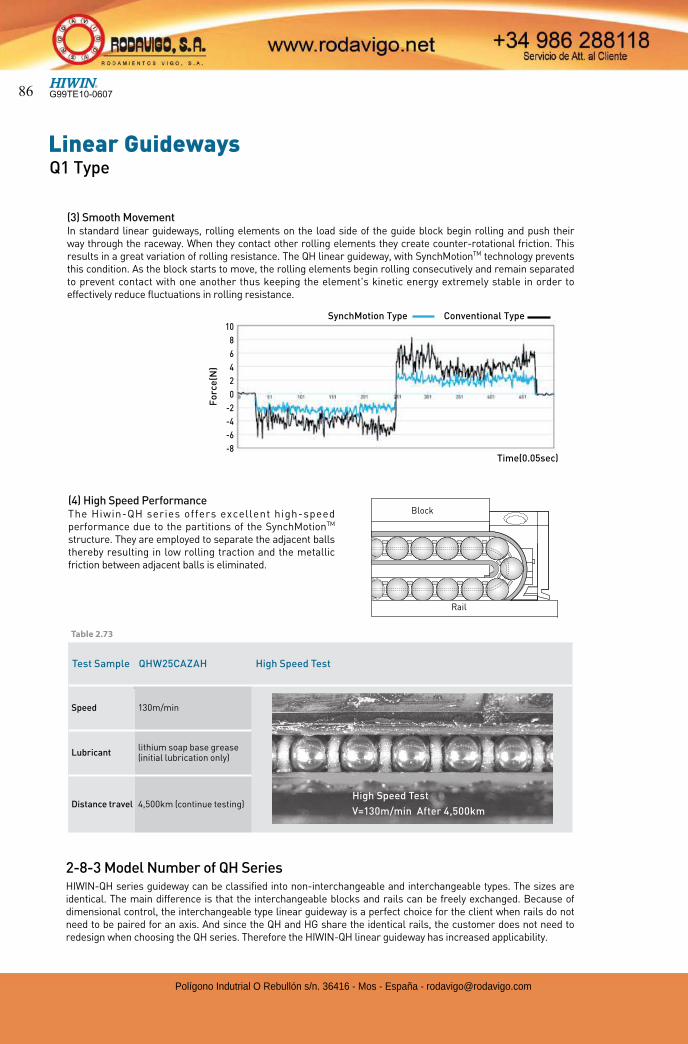
Linear GuidewaysQ1 Type
2-8-3 Model Number of QH SeriesHIWIN-QH series guideway can be classified into non-interchangeable and interchangeable types. The sizes are identical. The main difference is that the interchangeable blocks and rails can be freely exchanged. Because of dimensional control, the interchangeable type linear guideway is a perfect choice for the client when rails do not need to be paired for an axis. And since the QH and HG share the identical rails, the customer does not need to redesign when choosing the QH series. Therefore the HIWIN-QH linear guideway has increased applicability.
High Speed Test
Test Sample QHW25CAZAH High Speed Test
Speed 130m/min
Lubricantlithium soap base grease (initial lubrication only)
Distance travel 4,500km (continue testing)High Speed Test
V=130m/min After 4,500km
(3) Smooth MovementIn standard linear guideways, rolling elements on the load side of the guide block begin rolling and push their way through the raceway. When they contact other rolling elements they create counter-rotational friction. This results in a great variation of rolling resistance. The QH linear guideway, with SynchMotionTM technology prevents this condition. As the block starts to move, the rolling elements begin rolling consecutively and remain separated to prevent contact with one another thus keeping the element's kinetic energy extremely stable in order to effectively reduce fluctuations in rolling resistance.
Fo
rce
(N)
Time(0.05sec)
10
8
6
4
2
0
-2
-4
-6
-8
SynchMotion Type Conventional Type
(4) High Speed PerformanceThe Hiwin-QH series offers excellent high-speed performance due to the partitions of the SynchMotionTM structure. They are employed to separate the adjacent balls thereby resulting in low rolling traction and the metallic friction between adjacent balls is eliminated.
Block
Rail
Table 2.73
G99TE10-060786
Polígono Indutrial O Rebullón s/n. 36416 - Mos - España - [email protected]
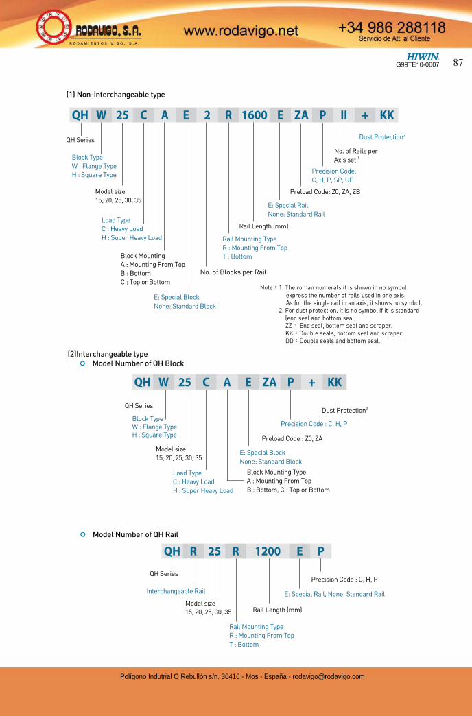
(1) Non-interchangeable type
(2)Interchangeable type ¢ Model Number of QH Block
¢ Model Number of QH Rail
QH Series
Rail Mounting Type
R : Mounting From Top
T : Bottom
Rail Length (mm)
E: Special Rail, None: Standard Rail
Precision Code : C, H, P
Interchangeable Rail
QH Series
Block Type
W : Flange Type
H : Square Type
Model size
15, 20, 25, 30, 35
E: Special Block
None: Standard Block
No. of Blocks per Rail
Rail Length (mm)
E: Special Rail
None: Standard Rail
Rail Mounting Type
R : Mounting From Top
T : Bottom
Preload Code: Z0, ZA, ZB
Precision Code:
C, H, P, SP, UP
No. of Rails per
Axis set 1
Dust Protection2
QH W 25 C A E 2 R 1600 E ZA P II + KK
Load Type
C : Heavy Load
H : Super Heavy Load
Block Mounting
A : Mounting From Top
B : Bottom
C : Top or Bottom
Model size
15, 20, 25, 30, 35
QH R 25 R 1200 E P
Note 1. The roman numerals it is shown in no symbol express the number of rails used in one axis. As for the single rail in an axis, it shows no symbol.
2. For dust protection, it is no symbol if it is standard(end seal and bottom seal).ZZ End seal, bottom seal and scraper.KK Double seals, bottom seal and scraper.DD Double seals and bottom seal.
QH Series
Block Type W : Flange Type H : Square Type
Block Mounting Type
A : Mounting From Top
B : Bottom, C : Top or Bottom
E: Special Block
None: Standard Block
Dust Protection2
Precision Code : C, H, P
Preload Code : Z0, ZA
Model size
15, 20, 25, 30, 35
Load Type
C : Heavy Load
H : Super Heavy Load
QH W 25 C A E ZA P + KK
G99TE10-0607 87
Polígono Indutrial O Rebullón s/n. 36416 - Mos - España - [email protected]
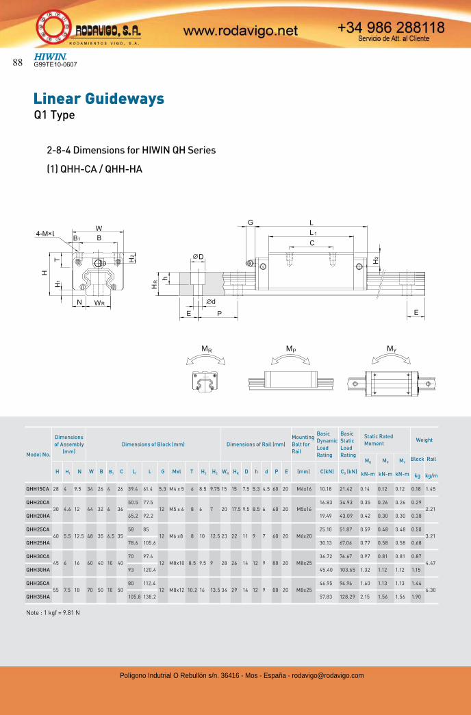
Linear GuidewaysQ1 Type
Model No.
Dimensions
of Assembly
(mm)
Dimensions of Block (mm) Dimensions of Rail (mm)
Mounting
Bolt for
Rail
Basic
Dynamic
Load
Rating
Basic
Static
Load
Rating
Static Rated
MomentWeight
MR
kN-m
MP
kN-m
MY
kN-m
Block
kg
Rail
kg/mH H1 N W B B1 C L1 L G Mxl T H2 H3 WR HR D h d P E (mm) C(kN) C0 (kN)
QHH15CA 28 4 9.5 34 26 4 26 39.4 61.4 5.3 M4 x 5 6 8.5 9.75 15 15 7.5 5.3 4.5 60 20 M4x16 10.18 21.42 0.14 0.12 0.12 0.18 1.45
QHH20CA
30 4.6 12 44 32 6 36
50.5 77.5
12 M5 x 6 8 6 7 20 17.5 9.5 8.5 6 60 20 M5x16
16.83 34.93 0.35 0.26 0.26 0.29
2.21
QHH20HA 65.2 92.2 19.49 43.09 0.42 0.30 0.30 0.38
QHH25CA
40 5.5 12.5 48 35 6.5 35
58 85
12 M6 x8 8 10 12.5 23 22 11 9 7 60 20 M6x20
25.10 51.87 0.59 0.48 0.48 0.50
3.21
QHH25HA 78.6 105.6 30.13 67.06 0.77 0.58 0.58 0.68
QHH30CA
45 6 16 60 40 10 40
70 97.4
12 M8x10 8.5 9.5 9 28 26 14 12 9 80 20 M8x25
36.72 76.67 0.97 0.81 0.81 0.87
4.47
QHH30HA 93 120.4 45.40 103.65 1.32 1.12 1.12 1.15
QHH35CA
55 7.5 18 70 50 10 50
80 112.4
12 M8x12 10.2 16 13.5 34 29 14 12 9 80 20 M8x25
46.95 94.96 1.60 1.13 1.13 1.44
6.30
QHH35HA 105.8 138.2 57.83 128.29 2.15 1.56 1.56 1.90
Note : 1 kgf = 9.81 N
2-8-4 Dimensions for HIWIN QH Series
(1) QHH-CA / QHH-HA
l
G99TE10-060788
Polígono Indutrial O Rebullón s/n. 36416 - Mos - España - [email protected]
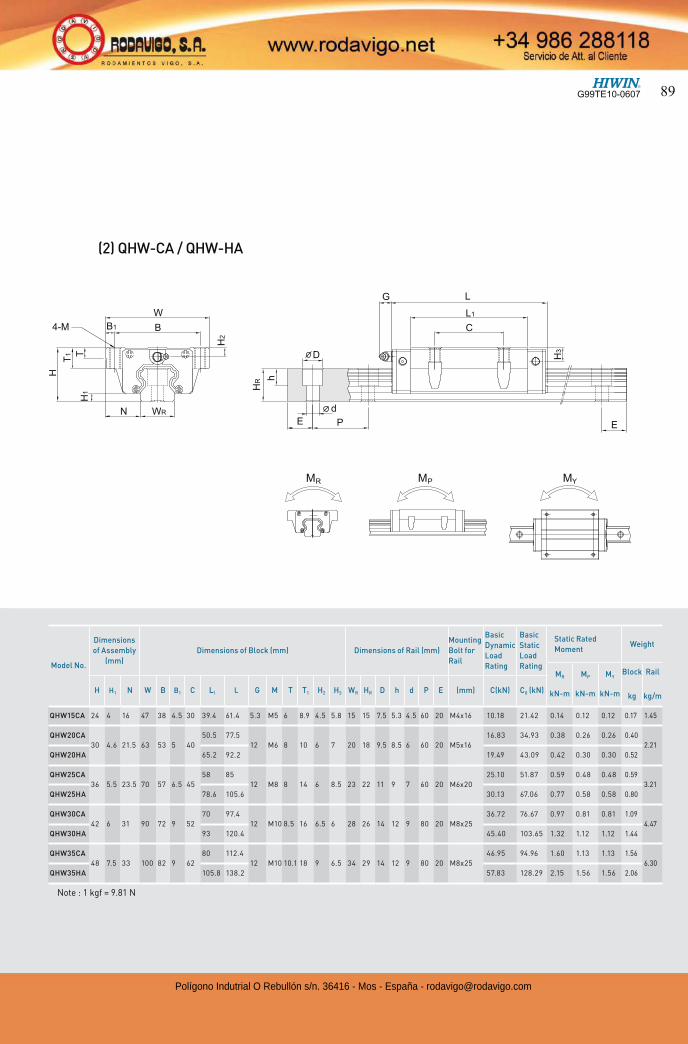
(2) QHW-CA / QHW-HA
Model No.
Dimensions
of Assembly
(mm)
Dimensions of Block (mm) Dimensions of Rail (mm)
Mounting
Bolt for
Rail
Basic
Dynamic
Load
Rating
Basic
Static
Load
Rating
Static Rated
MomentWeight
MR
kN-m
MP
kN-m
MY
kN-m
Block
kg
Rail
kg/mH H1 N W B B1 C L1 L G M T T1 H2 H3 WR HR D h d P E (mm) C(kN) C0 (kN)
QHW15CA 24 4 16 47 38 4.5 30 39.4 61.4 5.3 M5 6 8.9 4.5 5.8 15 15 7.5 5.3 4.5 60 20 M4x16 10.18 21.42 0.14 0.12 0.12 0.17 1.45
QHW20CA
30 4.6 21.5 63 53 5 40
50.5 77.5
12 M6 8 10 6 7 20 18 9.5 8.5 6 60 20 M5x16
16.83 34.93 0.38 0.26 0.26 0.40
2.21
QHW20HA 65.2 92.2 19.49 43.09 0.42 0.30 0.30 0.52
QHW25CA
36 5.5 23.5 70 57 6.5 45
58 85
12 M8 8 14 6 8.5 23 22 11 9 7 60 20 M6x20
25.10 51.87 0.59 0.48 0.48 0.59
3.21
QHW25HA 78.6 105.6 30.13 67.06 0.77 0.58 0.58 0.80
QHW30CA
42 6 31 90 72 9 52
70 97.4
12 M10 8.5 16 6.5 6 28 26 14 12 9 80 20 M8x25
36.72 76.67 0.97 0.81 0.81 1.09
4.47
QHW30HA 93 120.4 45.40 103.65 1.32 1.12 1.12 1.44
QHW35CA
48 7.5 33 100 82 9 62
80 112.4
12 M10 10.1 18 9 6.5 34 29 14 12 9 80 20 M8x25
46.95 94.96 1.60 1.13 1.13 1.56
6.30
QHW35HA 105.8 138.2 57.83 128.29 2.15 1.56 1.56 2.06
Note : 1 kgf = 9.81 N
G99TE10-0607 89
Polígono Indutrial O Rebullón s/n. 36416 - Mos - España - [email protected]
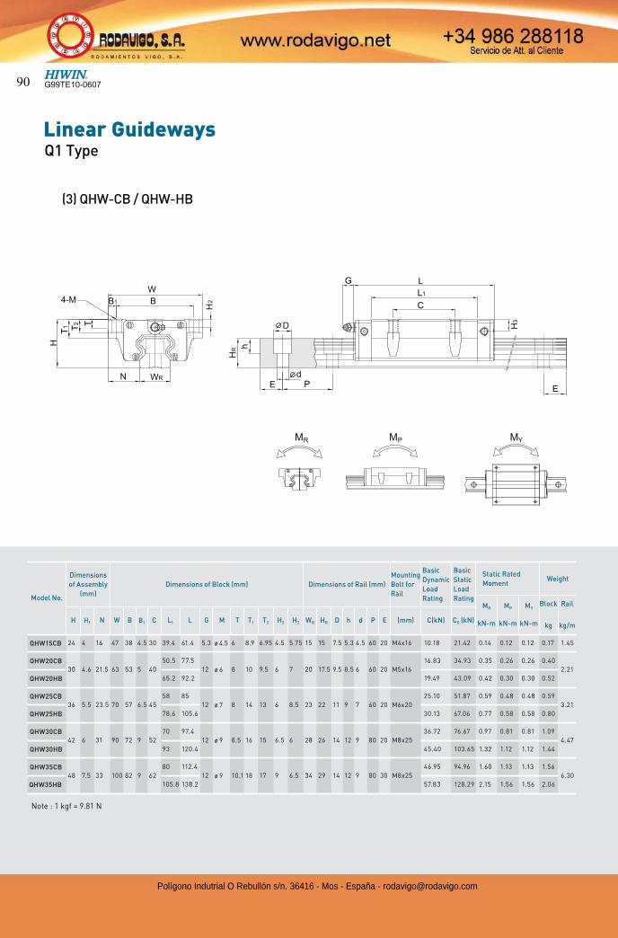
Linear GuidewaysQ1 Type
Note : 1 kgf = 9.81 N
Model No.
Dimensions
of Assembly
(mm)
Dimensions of Block (mm) Dimensions of Rail (mm)
Mounting
Bolt for
Rail
Basic
Dynamic
Load
Rating
Basic
Static
Load
Rating
Static Rated
MomentWeight
MR
kN-m
MP
kN-m
MY
kN-m
Block
kg
Rail
kg/mH H1 N W B B1 C L1 L G M T T1 T2 H2 H3 WR HR D h d P E (mm) C(kN) C0 (kN)
QHW15CB 24 4 16 47 38 4.5 30 39.4 61.4 5.3 ø 4.5 6 8.9 6.95 4.5 5.75 15 15 7.5 5.3 4.5 60 20 M4x16 10.18 21.42 0.14 0.12 0.12 0.17 1.45
QHW20CB30 4.6 21.5 63 53 5 40
50.5 77.5
12 ø 6 8 10 9.5 6 7 20 17.5 9.5 8.5 6 60 20 M5x16
16.83 34.93 0.35 0.26 0.26 0.40
2.21
QHW20HB 65.2 92.2 19.49 43.09 0.42 0.30 0.30 0.52
QHW25CB36 5.5 23.5 70 57 6.5 45
58 85
12 ø 7 8 14 13 6 8.5 23 22 11 9 7 60 20 M6x20
25.10 51.87 0.59 0.48 0.48 0.59
3.21
QHW25HB 78.6 105.6 30.13 67.06 0.77 0.58 0.58 0.80
QHW30CB42 6 31 90 72 9 52
70 97.4
12 ø 9 8.5 16 15 6.5 6 28 26 14 12 9 80 20 M8x25
36.72 76.67 0.97 0.81 0.81 1.09
4.47
QHW30HB 93 120.4 45.40 103.65 1.32 1.12 1.12 1.44
QHW35CB48 7.5 33 100 82 9 62
80 112.4
12 ø 9 10.1 18 17 9 6.5 34 29 14 12 9 80 30 M8x25
46.95 94.96 1.60 1.13 1.13 1.56
6.30
QHW35HB 105.8 138.2 57.83 128.29 2.15 1.56 1.56 2.06
(3) QHW-CB / QHW-HB
G99TE10-060790
Polígono Indutrial O Rebullón s/n. 36416 - Mos - España - [email protected]
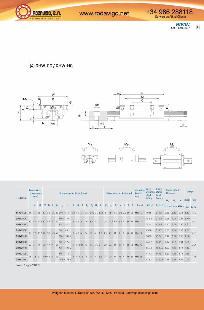
Model No.
Dimensions
of Assembly
(mm)
Dimensions of Block (mm) Dimensions of Rail (mm)
Mounting
Bolt for
Rail
Basic
Dynamic
Load
Rating
Basic
Static
Load
Rating
Static Rated
MomentWeight
MR
kN-m
MP
kN-m
MY
kN-m
Block
kg
Rail
kg/mH H1 N W B B1 C L1 L G M T T1 T2 H2 H3 WR HR D h d P E (mm) C(kN) C0 (kN)
QHW15CC 24 4 16 47 38 4.5 30 39.4 61.4 5.3 M5 6 8.9 6.95 4.5 5.75 15 15 7.5 5.3 4.5 60 20 M4x16 10.18 21.42 0.14 0.12 0.12 0.17 1.45
QHW20CC
30 4.6 21.5 63 53 5 40
50.5 77.5
12 M6 8 10 9.5 6 7 20 17.5 9.5 8.5 6 60 20 M5x16
16.83 34.93 0.35 0.26 0.26 0.40
2.21
QHW20HC 65.2 92.2 19.49 43.09 0.42 0.30 0.30 0.52
QHW25CC
36 5.5 23.5 70 57 6.5 45
58 85
12 M8 8 14 10 6 8.5 23 22 11 9 7 60 20 M6x20
25.10 51.87 0.59 0.48 0.48 0.59
3.21
QHW25HC 78.6 105.6 30.13 67.06 0.77 0.58 0.58 0.80
QHW30CC
42 6 31 90 72 9 52
70 97.4
12 M10 8.5 16 10 6.5 6 28 26 14 12 9 80 20 M8x25
36.72 76.67 0.97 0.81 0.81 1.09
4.47
QHW30HC 93 120.4 45.40 103.65 1.32 1.12 1.12 1.44
QHW35CC
48 7.5 33 100 82 9 62
80 112.4
12 M10 10.1 18 13 9 6.5 34 29 14 12 9 80 30 M8x25
46.95 94.96 1.60 1.13 1.13 1.56
6.30
QHW35HC 105.8 138.2 57.83 128.29 2.15 1.56 1.56 2.06
(4) QHW-CC / QHW-HC
Note : 1 kgf = 9.81 N
G99TE10-0607 91
Polígono Indutrial O Rebullón s/n. 36416 - Mos - España - [email protected]