Embed Size (px)
Citation preview
2” HIGH PRESSURE CLEAR WATER PUMP With 6.5 HP Gas Engine - CARB/EPA
Model 65351ASSEMBLy And OPERATIOn InSTRUCTIOnS
Visit our website at: http://www.harborfreight.com
Read this material before using this product. Failure to do so can result in serious injury. SAVE THIS MAnUAL.
Copyright© 2008 by Harbor Freight Tools®. All rights reserved. No portion of this manual or any artwork contained herein may be reproduced in any shape or form without the express written consent of Harbor Freight Tools. Diagrams within this manual may not be drawn proportionally. Due to continuing improvements, actual product may differ slightly from the product described herein. Tools required for assembly and service may not be included.
For technical questions or replacement parts, please call 1-800-444-3353.Manual Revised 10c; 10b; 09j
Using an engine indoors CAn KILL yOU In MInUTES.Engine exhaust contains carbon monoxide. This is a poison you cannot see or smell.
nEVER use inside a home or garage, EVEn IF doors and windows are open.
Only use OUTSIdE and far away from windows, doors, and vents.

Page 2 For technical questions, please call 1-800-444-3353. SKU 65351
SPECIFICATIOnSSuction Port Diameter 2” TPI
Discharge Port Diameter 2” TPI
Maximum Suction Head 25 ft.
Total Head 187 ft.
Maximum Discharge Capacity 108 GPM
Pump Type Centrifugal / Self-Priming*
Pump RPM 3600
Engine Specifications
6.5 HP, OHV / 4-Stroke / Recoil Start / 3 hr. Run-Time Displacement: 196cc Rotation: Counterclockwise (from shaft side) Unleaded Fuel: Min. 87 OctaneFuel Tank Capacity: 1 Gallon Engine Oil Capacity: 27 Oz.
Included Accessories
Plastic Basket FilterHose Coupling Hose Adapters / Barbed Fittings / Gasket / Wire Clamps
* The Water Pump is self-priming. However, for initial use the Pump Housing must be filled with water (see page 9).
IMPORTAnT! THIS PUMP IS FOR CLEAR WATER USE OnLy. Clear water is water that contains little to no solids.
IMPORTAnT! This product requires oil and fuel to be added before starting. Attempting to start the Engine without oil WILL ruin the Engine and void the warranty.
The Emission Control System for this Water Pump’s Engine is warranted for standards set by the U.S. Environmental Protection Agency and by the California Air Resources Board (also known as CARB). For warranty information, refer to the last two pages of this manual.
nOTE: At high altitudes, the engine’s carburetor, governor (if so equipped), and any other parts that control the fuel-air ratio will need to be adjusted by a qualified mechanic to allow efficient high-altitude use and to prevent damage to the engine and any other devices used with this product.
SAVE THIS MAnUALYou will need this manual for safety
warnings and precautions, assembly, operating, inspection, maintenance and cleaning procedures, parts list and assembly diagram. Keep invoice with manual. Write invoice number on inside of front cover. Write product’s serial number in back of manual near assembly diagram, or write month and year of purchase if product has no number. Keep manual and invoice in a safe and dry place for future reference.
Pump ApplicationsClear Water ** •
Slimy Water •
Muck Water •
Silt Water •
High Solid Content N/A
Slow Seepage N/A
Fast Seepage •
Manholes •
Cofferdams •
Quarries •
Septic Tanks N/A
Deep Piling N/A
Industrial/ Agricultural Chemicals N/A
This Water Pump can be used to supply water to:
Mixer or Paver N/A
Concrete Curing N/A
Water Wagons ** N/A
Sprinklers or Nozzle •
** Non Potable Only N/A = Not Applicable

Page 3For technical questions, please call 1-800-444-3353.SKU 65351
IMPORTAnT SAFETy InFORMATIOn
In this manual, on the labeling, and all other information provided with this product:
This is the safety alert symbol. It is used to alert you to potential personal injury hazards. Obey all safety messages that follow this symbol to avoid possible injury or death.
dAnGER indicates a hazardous situation
which, if not avoided, will result in death or serious injury.
WARnInG indicates a hazardous situation
which, if not avoided, could result in death or serious injury.
CAUTIOn, used with the safety alert
symbol, indicates a hazardous situation which, if not avoided, could result in minor or moderate injury.
nOTICE is used to address practices not
related to personal injury.
CAUTIOn, without the safety alert symbol, is
used to address practices not related to personal injury.
WARnInG! Read all instructions. Failure to follow all instructions listed below may result in fire, serious injury and/or dEATH. The warnings and precautions discussed in this manual cannot cover
all possible conditions and situations that may occur. It must be understood by the operator that common sense and caution are factors which cannot be built into this product, but must be supplied by the operator.
SAVE THESE InSTRUCTIOnS
SET UP PRECAUTIOnSGasoline fuel and fumes are flammable, 1. and potentially explosive. Use proper fuel storage and handling procedures. Do not store fuel or other flammable materials nearby.
Have multiple ABC class fire 2. extinguishers nearby.
Operation of this equipment may create 3. sparks that can start fires around dry vegetation. A spark arrestor may be required. The operator should contact local fire agencies for laws or regulations relating to fire prevention requirements.
Set up and use only on a flat, level, well-4. ventilated surface.
Wear ANSI-approved safety goggles, 5. heavy-duty work gloves, and dust mask/respirator during set up.
Use only oil and fuel recommended 6. in the “Specifications” section of this manual.
Do not use gasoline containing more 7. than 10% ethanol (E10). Do not use E85 ethanol.
Page 4 For technical questions, please call 1-800-444-3353. SKU 65351
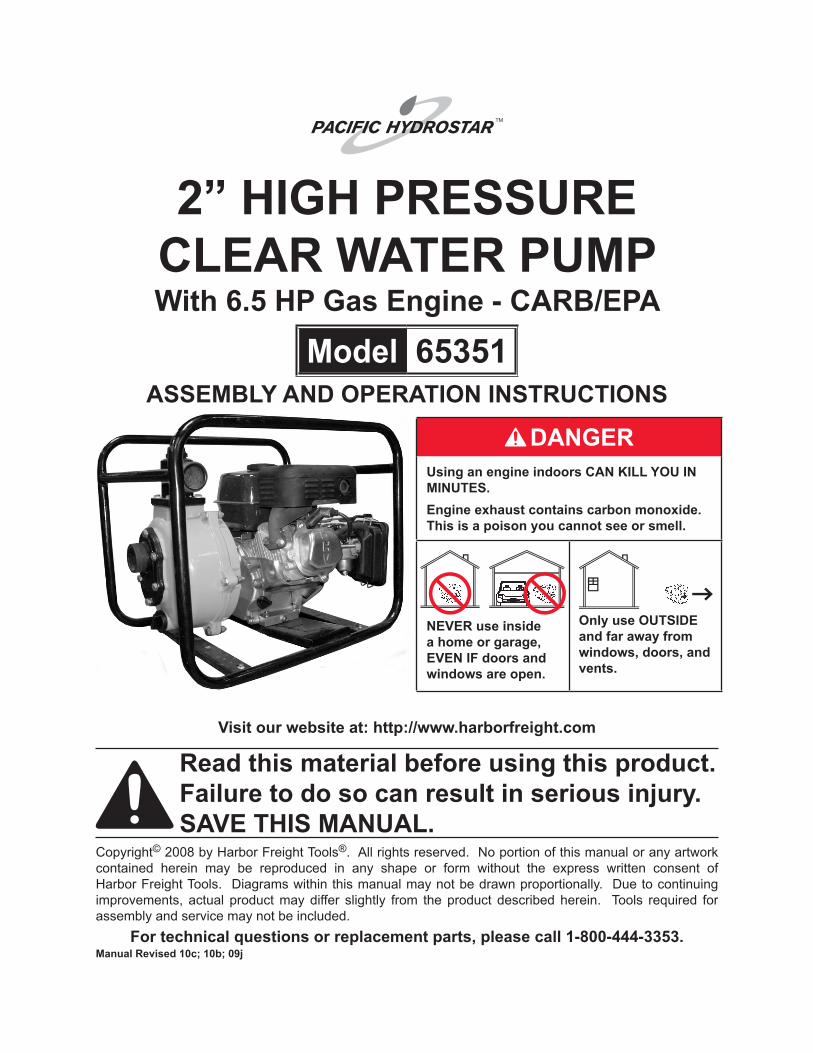
OPERATInG PRECAUTIOnS1. CARBOn MOnOxIdE
HAzARd Using an engine indoors CAn KILL yOU In MInUTES. Engine exhaust contains
carbon monoxide. This is a poison you cannot see or smell.
NEVER use inside a home or garage, EVEN IF doors and windows are open.
Only use OUTSIDE and far away from windows, doors, and vents.
Keep children away from the equipment, 2. especially while it is operating.
Do not leave the equipment unattended 3. when it is running. Turn off the equipment (and remove safety keys, if available) before leaving the work area.
Wear ANSI-approved safety goggles and 4. hearing protection during use.
People with pacemakers should 5. consult their physician(s) before use. Electromagnetic fields in close proximity to a heart pacemaker could cause pacemaker interference or pacemaker failure. Caution is necessary when near the engine’s magneto or recoil starter.
Use only accessories that are 6. recommended by Harbor Freight Tools for your model. Accessories that may
be suitable for one piece of equipment may become hazardous when used on another piece of equipment.
Do not operate in explosive 7. atmospheres, such as in the presence of flammable liquids, gases, or dust. Gasoline-powered engines may ignite the dust or fumes.
Stay alert, watch what you are doing 8. and use common sense when operating this piece of equipment. Do not use this piece of equipment while tired or under the influence of drugs, alcohol or medication.
Do not overreach. Keep proper footing 9. and balance at all times. This enables better control of the equipment in unexpected situations.
Dress properly. Do not wear loose 10. clothing or jewelry. Keep hair, clothing and gloves away from moving parts. Loose clothes, jewelry or long hair can be caught in moving parts.
Parts, especially exhaust system 11. components, get very hot during use. Stay clear of hot parts.
Do not cover the engine or equipment 12. during operation.
Keep the equipment, engine, and 13. surrounding area clean at all times.
Use the equipment, accessories, etc., in 14. accordance with these instructions and in the manner intended for the particular type of equipment, taking into account the working conditions and the work to be performed. Use of the equipment for operations different from those intended could result in a hazardous situation.
Do not operate the equipment with 15. known leaks in the engine’s fuel system.

Page 5For technical questions, please call 1-800-444-3353.SKU 65351
WARNING: The brass components of 16. this product contain lead, a chemical known to the State of California to cause birth defects (or other reproductive harm). (California Health & Safety code § 25249.5, et seq.)
This product contains or, when used, 17. produces a chemical known to the State of California to cause cancer and birth defects or other reproductive harm. (California Health & Safety Code § 25249.5, et seq.)
When spills of fuel or oil occur, they must 18. be cleaned up immediately. Dispose of fluids and cleaning materials as per any local, state, or federal codes and regulations. Store oil rags in a bottom-ventilated, covered, metal container.
Keep hands and feet away from moving 19. parts. Do not reach over or across equipment while operating.
Before use, check for misalignment 20. or binding of moving parts, breakage of parts, and any other condition that may affect the equipment’s operation. If damaged, have the equipment serviced before using. Many accidents are caused by poorly maintained equipment.
Use the correct equipment for the 21. application. Do not modify the equipment and do not use the equipment for a purpose for which it is not intended.
Industrial applications must follow OSHA 22. guidelines.
SERVICE PRECAUTIOnSBefore service, maintenance, or 1. cleaning:Turn the Power Switch (6K) to its a. “OFF” position. nOTE: When ordering or referencing parts, each Assembly Diagram (at back of manual) has its own suffix letter (A, B, C, etc.) Be sure to add the correct suffix letter when ordering replacement parts.Allow the engine to completely cool.b. Then, remove the Spark Plug (10D).c.
Keep all safety guards in place and in 2. proper working order. Safety guards include muffler, air cleaner, mechanical guards, and heat shields, among other guards.
do not alter or adjust any part of the 3. equipment or its engine that is sealed by the manufacturer or distributor. Only a qualified service technician may adjust parts that may increase or decrease governed engine speed.
Wear ANSI-approved safety goggles, 4. heavy-duty work gloves, and dust mask/respirator during service.
Maintain labels and nameplates on 5. the equipment. These carry important information. If unreadable or missing, contact Harbor Freight Tools for a replacement.
Have the equipment serviced by a 6. qualified repair person using only identical replacement parts. This will ensure that the safety of the equipment is maintained. Do not attempt any service or maintenance procedures not explained in this manual or any

Page 6 For technical questions, please call 1-800-444-3353. SKU 65351
procedures that you are uncertain about your ability to perform safely or correctly.
Store equipment out of the reach of 7. children.
Follow scheduled engine and equipment 8. maintenance.
Refueling Precautions:9. Do not smoke, or allow sparks, flames, a. or other sources of ignition around the equipment, especially when refuelling.Do not refill the fuel tank while the b. engine is running or hot.
Do not fill fuel tank to the top. Leave c. a little room for the fuel to expand as needed.Refuel in a well-ventilated area only.d.
SAVE THESE InSTRUCTIOnS.
UnPACKInGWhen unpacking, check to make sure
all of the parts shown on the Parts List in this manual are included. If any parts are missing or broken, please call Harbor Freight Tools at the number shown on the cover (and at the bottom of each page) of this manual as soon as possible.
dIPSTICK(8C)
POWER SWITCH(6K)
OIL dRAIn PLUG(1B)
STARTERHAndLE
(16K)
AIRCLEANER COVER (2I)
CHOKE(22G)
FUELLEVER(21K)
THROTTLE(23G)
FUEL TANK CAP (9H)
FUEL TAnK(11H)
MUFFLER(4J)
WATERPRIMERPLUG
(8)DISCHARGE FLANGE (33)
(Discharge Hose Connector)
WATERdRAInPLUG(1B)
INTAKE FLANGE (3) (Suction Hose Connector)
COnTROLS And FEATURES
COUPLInG GASKET
(38)
HOSE COUPLInG
(34)
InTAKE FILTER
(37)
InTAKE FILTER
COVER (36)
HOSE CLAMPS
(39)
HOSE COUPLER (35)
Page 7For technical questions, please call 1-800-444-3353.SKU 65351
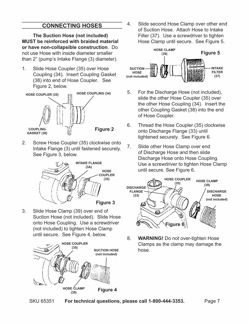
COnnECTInG HOSESThe Suction Hose (not included)
MUST be reinforced with braided material or have non-collapsible construction. Do not use Hose with inside diameter smaller than 2” (pump’s Intake Flange (3) diameter).
Slide Hose Coupler (35) over Hose 1. Coupling (34). Insert Coupling Gasket (38) into end of Hose Coupler. See Figure 2, below.
Screw Hose Coupler (35) clockwise onto 2. Intake Flange (3) until fastened securely. See Figure 3, below.
Slide Hose Clamp (39) over end of 3. Suction Hose (not included). Slide Hose onto Hose Coupling. Use a screwdriver (not included) to tighten Hose Clamp until secure. See Figure 4, below.
Slide second Hose Clamp over other end 4. of Suction Hose. Attach Hose to Intake Filter (37). Use a screwdriver to tighten Hose Clamp until secure. See Figure 5.
For the Discharge Hose (not included), 5. slide the other Hose Coupler (35) over the other Hose Coupling (34). Insert the other Coupling Gasket (38) into the end of Hose Coupler.
Thread the Hose Coupler (35) clockwise 6. onto Discharge Flange (33) until tightened securely. See Figure 6.
Slide other Hose Clamp over end 7. of Discharge Hose and then slide Discharge Hose onto Hose Coupling. Use a screwdriver to tighten Hose Clamp until secure. See Figure 6.
WARnInG!8. Do not over-tighten Hose Clamps as the clamp may damage the hose.
Figure 2
HOSE COUPLER (35) HOSE COUPLING (34)
COUPLInG GASKET (38)
InTAKE FLAnGE(3A)
HOSE COUPLER
(35)
Figure 3
HOSE COUPLER (35)
HOSE CLAMP (39)
SUCTIOn HOSE (not included)
Figure 4
HOSE CLAMP (39)
SUCTIOn HOSE
(not included)
InTAKE FILTER
(37)
Figure 5
HOSE CLAMP (39)
dISCHARGE HOSE
(not included)
HOSE COUPLER (35)
dISCHARGE FLAnGE
(33)
Figure 6

Page 8 For technical questions, please call 1-800-444-3353. SKU 65351
LOCATInG THE WATER PUMPMake sure the Water Pump is located 1. on a flat, level, sturdy surface capable of supporting the weight of the Pump and any additional tools and equipment.
For best Pump performance, place the 2. Pump near the water level and use hoses that are no longer than necessary. That will allow the Pump to produce the greatest output with the least self-priming time. See diagram below. As the head (pumping height) increases, pump output decreases. The length, type, and size of the suction and discharge hoses can also significantly affect Pump output. Discharge head capability is always greater than suction head capability. Which means pumping height for the Intake Hose (suction head) should be shorter than the pumping height for the Discharge Hose. Minimizing suction head (placing the Pump closer to the water level) will also help reduce self-priming time. This is the time it takes the Pump to bring the water from the water level to the Pump during the initial operation.
Route the Intake Hose with the Intake 3. Filter fully immersed in the water supply source.
Place Filter into water to be pumped. 4. WARnInG! Filter must be fully immersed in water. Do not operate Pump without Filter connected to end of suction hose. Keep Filter out of sand or silt by placing Filter in bucket or on stones. See diagram below.
Secure the Intake Hose in place to keep 5. it from moving once the Pump is turned on. The Intake Hose should be as short as possible for more efficient operation.
Route the discharge hose to the desired 6. discharge location. If necessary, connect additional discharge hoses to direct the discharge to the desired location. Then make sure to secure the discharge hose in place to keep it from moving once the Water Pump is turned on. The discharge hose should be kept as short as possible for more efficient operation.
CAUTIOn! 7. Be aware of the following problems during operation, and how to fix them: 1. Cavitation: This is the sudden formation and collapse of low-pressure vapor (bubbles) across the vanes of the impeller. Cause: When the surface pressure on a liquid becomes low enough, the
Total Head
Suction HeadWater Pump
discharge Head
Filter
Page 9For technical questions, please call 1-800-444-3353.SKU 65351
liquid will begin to boil (even at room temperature). With centrifugal pumps, cavitation can occur when the suction vacuum becomes too great, allowing water vapor or bubbles to form at the impeller. The rapid pressure increase can cause impeller damage. Solution: Minimizing suction head and using the largest practical suction hose diameter will reduce the likelihood of cavitation. do not use a suction hose with a diameter smaller than the Pump’s Flange (2” diameter). 2. Water Hammer Pressure: This is energy sent back to the Pump due to sudden stoppage of water flowing from the Pump. Cause: Water hammer pressure is more likely to occur when using a very long discharge hose. If the flow of water at the end of the discharge hose is shut off suddenly, energy is sent back to the pump. This causes a large pressure spike in the Pump housing, leading to potential damage to the Pump casing. Solution: Use as short a discharge hose as possible or shut off water flow slowly.
OPERATInG InSTRUCTIOnS Read the EnTIRE IMPORTAnT
SAFETy InFORMATIOn section at the beginning of this manual including all text under subheadings therein before set up or use of this product.
Starting the Engine Inspect Engine and Water Pump
for damaged, loose, and missing parts before set up and starting.
If any problems are found, do not use until properly repaired.
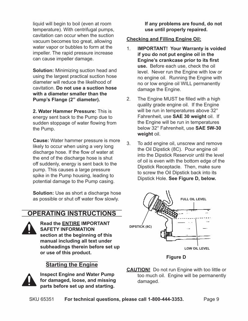
Checking and Filling Engine Oil:
IMPORTAnT! your Warranty is voided 1. if you do not put engine oil in the Engine’s crankcase prior to its first use. Before each use, check the oil level. Never run the Engine with low or no engine oil. Running the Engine with no or low engine oil WILL permanently damage the Engine.
The Engine MUST be filled with a high 2. quality grade engine oil. If the Engine will be run in temperatures above 32° Fahrenheit, use SAE 30 weight oil. If the Engine will be run in temperatures below 32° Fahrenheit, use SAE 5W-30 weight oil.
To add engine oil, unscrew and remove 3. the Oil Dipstick (8C). Pour engine oil into the Dipstick Reservoir until the level of oil is even with the bottom edge of the Dipstick Receptacle. Then, make sure to screw the Oil Dipstick back into its Dipstick Hole. See Figure d, below.
CAUTIOn! Do not run Engine with too little or too much oil. Engine will be permanently damaged.
DIPSTICK (8C)
Figure d
LOW OIL LEVEL
FULL OIL LEVEL
Page 10 For technical questions, please call 1-800-444-3353. SKU 65351
Checking and Filling Fuel:
Check the fuel level.1.
WARnInG! TO PREVEnT SERIOUS INJURy FROm FIRE: Fill the Fuel Tank (11H) in a well-ventilated area away from ignition
sources. Do not smoke.
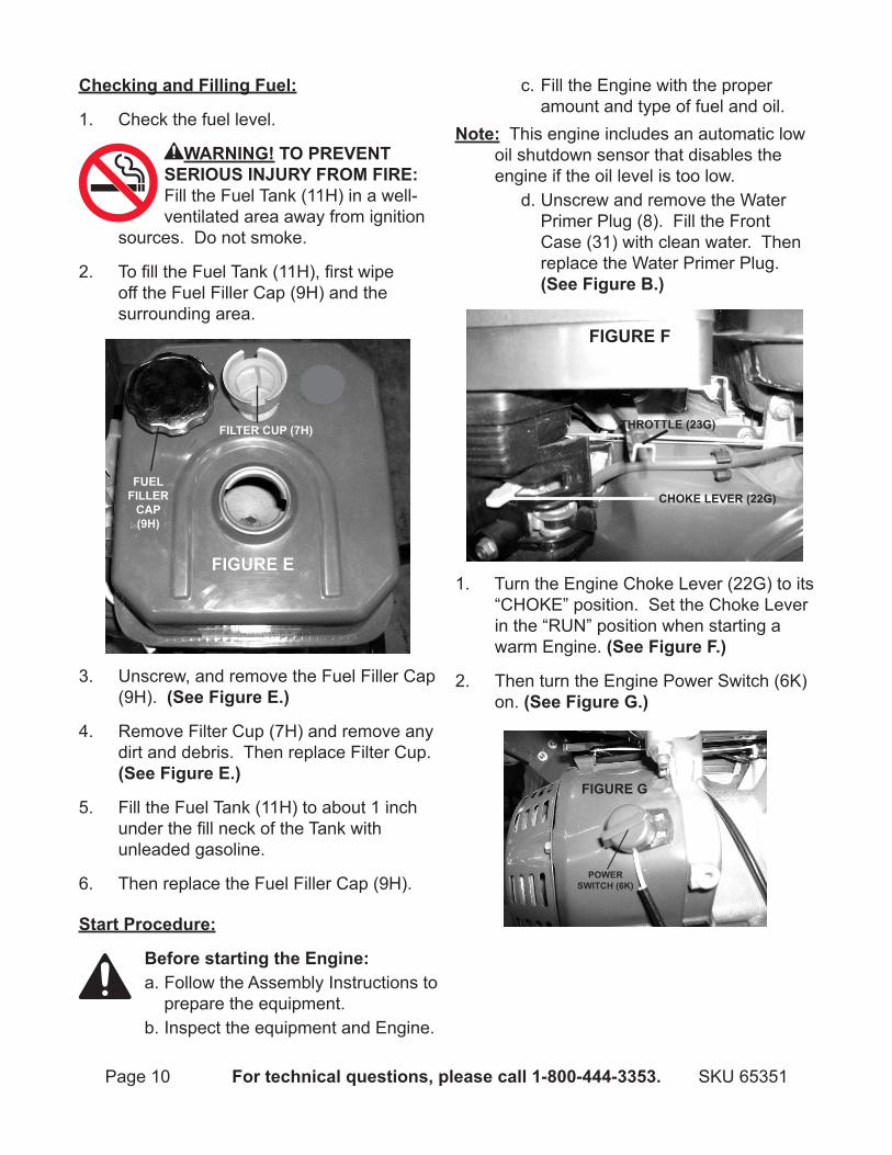
To fill the Fuel Tank (11H), first wipe 2. off the Fuel Filler Cap (9H) and the surrounding area.
FIGURE E
FUELFILLER
CAP(9H)
FILTER CUP (7H)
3. Unscrew, and remove the Fuel Filler Cap (9H). (See Figure E.)
Remove Filter Cup (7H) and remove any 4. dirt and debris. Then replace Filter Cup. (See Figure E.)
Fill the Fuel Tank (11H) to about 1 inch 5. under the fill neck of the Tank with unleaded gasoline.
Then replace the Fuel Filler Cap (9H).6.
Start Procedure:
Before starting the Engine:Follow the Assembly Instructions to a. prepare the equipment.Inspect the equipment and Engine.b.
Fill the Engine with the proper c. amount and type of fuel and oil.
note: This engine includes an automatic low oil shutdown sensor that disables the engine if the oil level is too low.
Unscrew and remove the Water d. Primer Plug (8). Fill the Front Case (31) with clean water. Then replace the Water Primer Plug. (See Figure B.)
FIGURE F
CHOKE LEVER (22G)
THROTTLE (23G)
1. Turn the Engine Choke Lever (22G) to its “CHOKE” position. Set the Choke Lever in the “RUN” position when starting a warm Engine. (See Figure F.)
Then turn the Engine Power Switch (6K) 2. on. (See Figure G.)
FIGURE G
POWERSWITCH (6K)
Page 11For technical questions, please call 1-800-444-3353.SKU 65351
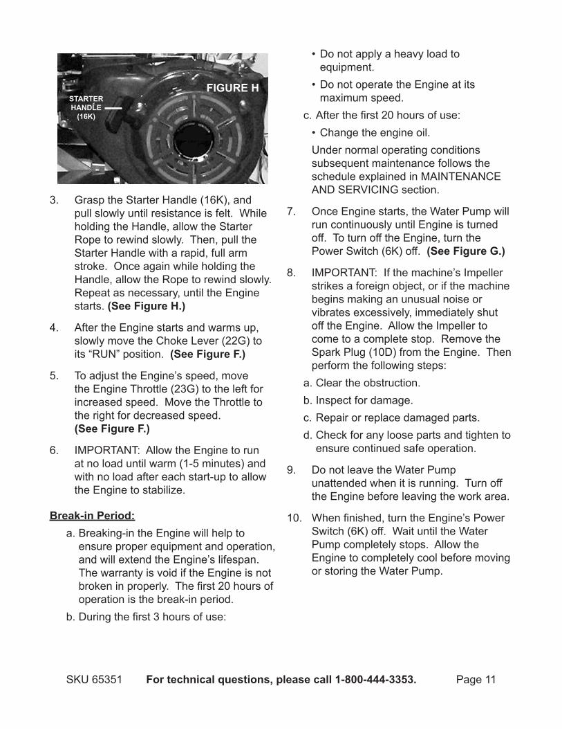
FIGURE HSTARTERHAndLE
(16K)
3. Grasp the Starter Handle (16K), and pull slowly until resistance is felt. While holding the Handle, allow the Starter Rope to rewind slowly. Then, pull the Starter Handle with a rapid, full arm stroke. Once again while holding the Handle, allow the Rope to rewind slowly. Repeat as necessary, until the Engine starts. (See Figure H.)
After the Engine starts and warms up, 4. slowly move the Choke Lever (22G) to its “RUN” position. (See Figure F.)
To adjust the Engine’s speed, move 5. the Engine Throttle (23G) to the left for increased speed. Move the Throttle to the right for decreased speed. (See Figure F.)
IMPORTANT: Allow the Engine to run 6. at no load until warm (1-5 minutes) and with no load after each start-up to allow the Engine to stabilize.
Break-in Period:Breaking-in the Engine will help to a. ensure proper equipment and operation, and will extend the Engine’s lifespan. The warranty is void if the Engine is not broken in properly. The first 20 hours of operation is the break-in period.During the first 3 hours of use:b.
Do not apply a heavy load to • equipment.Do not operate the Engine at its • maximum speed.
After the first 20 hours of use:c. Change the engine oil.•
Under normal operating conditions subsequent maintenance follows the schedule explained in MAINTENANCE AND SERVICING section.
Once Engine starts, the Water Pump will 7. run continuously until Engine is turned off. To turn off the Engine, turn the Power Switch (6K) off. (See Figure G.)
IMPORTANT: 8. If the machine’s Impeller strikes a foreign object, or if the machine begins making an unusual noise or vibrates excessively, immediately shut off the Engine. Allow the Impeller to come to a complete stop. Remove the Spark Plug (10D) from the Engine. Then perform the following steps:Clear the obstruction.a. Inspect for damage.b. Repair or replace damaged parts.c. Check for any loose parts and tighten to d. ensure continued safe operation.
Do not leave the Water Pump 9. unattended when it is running. Turn off the Engine before leaving the work area.
When finished, turn the Engine’s Power 10. Switch (6K) off. Wait until the Water Pump completely stops. Allow the Engine to completely cool before moving or storing the Water Pump.

Page 12 For technical questions, please call 1-800-444-3353. SKU 65351
MAInTEnAnCE And SERVICInG
TO PREVEnT SERIOUS INJURy
FROM ACCIdEnTAL STARTInG: Turn the Power Switch of the Engine to its “OFF” position, wait for the Engine to cool, and remove the Spark Plug (10D) before performing any inspection, maintenance, or cleaning procedures.
TO PREVEnT SERIOUS INJURy
FROM EqUIPMEnT FAILURE: do not use damaged equipment. If abnormal noise, vibration, or excess smoking occurs, correct problem before further use.
Maintenance Procedures Many maintenance procedures,
including those not detailed in this manual, will need to be performed by a qualified technician for safety. If you have any doubts about your ability to safely service the equipment or Engine, have a qualified technician service the equipment instead.
note: Warranty is void if proper maintenance and servicing procedures are not followed.
Engine Oil Change:
CAUTIOn! Oil is very hot during operation and can cause burns. Wait for Engine to cool before changing oil.
Place a drain pan (not included) 1. underneath the crankcase’s Drain Plug (1B). (See Figure A.)
Remove the Drain Plug (1B) and, if 2. possible, tilt the Crankcase (5B) slightly to help drain the oil out. Recycle used oil. (See Figure A.)
Replace the Drain Plug (1B) and gasket 3. and tighten it. (See Figure A.)
Refill the oil to the proper level following 4. the instructions under the “Starting the Engine” section.
Air Filter Element Maintenance:
Wipe off the Air Cleaner Cover (2I).1.
The Air Cleaner Cover is held in place by 2. the Air Cleaner Base (8I). Remove it.
Remove the Air Filter Element (3I).3.
Wash the Air Filter Element in warm 4. water and mild detergent several times. Rinse. Squeeze out excess water and allow it to dry completely. Soak the Filter in lightweight oil briefly, then squeeze out the excess oil.
Install the new Air Filter Element or the 5. cleaned Filter. Secure the Air Cleaner Cover before use.
Spark Plug Maintenance:
Disconnect Spark Plug Wire from end 1. of plug. Clean out debris from around Spark Plug (10D).
Using a spark plug wrench, remove the 2. Spark Plug.
Inspect the Spark Plug: 3. If electrode is oily, clean it using a clean, dry rag. If electrode has deposits on it, polish it using emery paper. If white insulator is cracked or chipped, Spark Plug needs to be replaced.

Page 13For technical questions, please call 1-800-444-3353.SKU 65351
When installing a new Spark Plug, adjust 4. Plug’s gap to the specification on the Technical specification chart. Do not pry against the electrode or the insulator; the Spark Plug can be damaged.
Install the new Spark Plug or the cleaned 5. Spark Plug into the Engine. Gasket-style: Finger-tighten until the gasket contacts the cylinder head, then about 1/2-2/3 turn more. Non-gasket-style: Finger-tighten until plug contacts head, then 1/16 turn more.
Cleaning, Maintenance, and Lubrication Schedule: Engine
note: This maintenance schedule is intended solely as a general guide. If performance decreases or if the Engine operates unusually, check systems immediately. The maintenance needs this Engine will differ depending on factors such as temperature, air quality, fuel quality, and other factors.
note: These procedures are in addition to regular checks and maintenance explained as part of the regular operation of the Engine.
After Initial 20 Operation Hours:Change engine oil.a.
Every 25 Operation Hours Thereafter:Clean/replace Air Filter Element.a. Inspect/clean Spark Plug.b.
Every 50 Operation Hours:Change engine oil.a.
Every 100 Operation Hours:Replace Spark Plug.a. Replace Air Filter Element.b.
note: All maintenance procedures scheduled for 25, 50, and 100 operation hours should be performed at least yearly.
Every 300 Operation Hours:Clean Fuel Tank (11H) and Carburetor a. Assembly (28G).Clean carbon build-up from Combustion b. Chamber.
StorageOnce Engine cools, wipe with cloth.1.
When the equipment is to remain idle for 2. longer than 20 days, prepare the Engine for storage as follows:Change engine oil and empty Fuel Tank.a. Clean out area around Spark Plug. b. Remove Spark Plug and pour one tablespoon of engine oil into Cylinder through Spark Plug hole.Reinstall Spark Plug, but leave the c. Spark Plug Wire disconnected.Pull Starter Handle (16K) to distribute d. oil in Cylinder. Stop after one or two revolutions when you feel the Piston start the compression stroke (when you start to feel resistance).
Apply a thin coat of rust preventive oil to 3. all uncoated metal parts.
Cover and store in a dry, well-ventilated 4. area out of reach of children.
Maintenance and Cleaning Schedule: Water Pump
note: This maintenance schedule is intended solely as a general guide. If performance decreases or if equipment operates unusually, check systems immediately. The maintenance needs of this machine will differ depending on
Page 14 For technical questions, please call 1-800-444-3353. SKU 65351
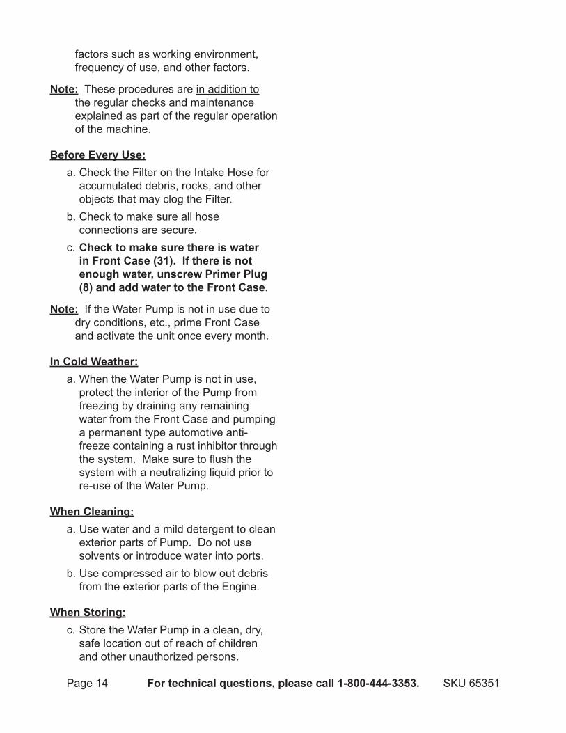
factors such as working environment, frequency of use, and other factors.
note: These procedures are in addition to the regular checks and maintenance explained as part of the regular operation of the machine.
Before Every Use:Check the Filter on the Intake Hose for a. accumulated debris, rocks, and other objects that may clog the Filter.Check to make sure all hose b. connections are secure.Check to make sure there is water c. in Front Case (31). If there is not enough water, unscrew Primer Plug (8) and add water to the Front Case.
note: If the Water Pump is not in use due to dry conditions, etc., prime Front Case and activate the unit once every month.
In Cold Weather:When the Water Pump is not in use, a. protect the interior of the Pump from freezing by draining any remaining water from the Front Case and pumping a permanent type automotive anti-freeze containing a rust inhibitor through the system. Make sure to flush the system with a neutralizing liquid prior to re-use of the Water Pump.
When Cleaning:Use water and a mild detergent to clean a. exterior parts of Pump. Do not use solvents or introduce water into ports.Use compressed air to blow out debris b. from the exterior parts of the Engine.
When Storing:Store the Water Pump in a clean, dry, c. safe location out of reach of children and other unauthorized persons.
Page 15For technical questions, please call 1-800-444-3353.SKU 65351
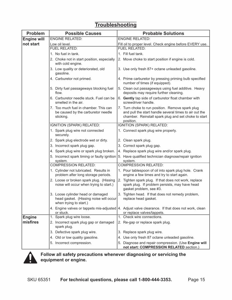
TroubleshootingProblem Possible Causes Probable Solutions
Engine will not start
ENGINE RELATED:Low oil level.
ENGINE RELATED:Fill oil to proper level. Check engine before EVERY use.
FUEL RELATED:No fuel in tank.1. Choke not in start position, especially 2. with cold engine.Low quality or deteriorated, old 3. gasoline.Carburetor not primed. 4.
Dirty fuel passageways blocking fuel 5. flow.Carburetor needle stuck. Fuel can be 6. smelled in the air.Too much fuel in chamber. This can 7. be caused by the carburetor needle sticking.
FUEL RELATED:Fill fuel tank.1. Move choke to start position if engine is cold. 2.
Use only fresh 87+ octane unleaded gasoline. 3.
Prime carburetor by pressing priming bulb specified 4. number of times (if equipped).Clean out passageways using fuel additive. Heavy 5. deposits may require further cleaning.Gently6. tap side of carburetor float chamber with screwdriver handle.Turn choke to run position. Remove spark plug 7. and pull the start handle several times to air out the chamber. Reinstall spark plug and set choke to start position.
IGNITION (SPARK) RELATED:Spark plug wire not connected 1. securely.Spark plug electrode wet or dirty.2. Incorrect spark plug gap.3. Spark plug wire or spark plug broken.4. Incorrect spark timing or faulty ignition 5. system.
IGNITION (SPARK) RELATED:Connect spark plug wire properly. 1.
Clean spark plug.2. Correct spark plug gap.3. Replace spark plug wire and/or spark plug.4. Have qualified technician diagnose/repair ignition 5. system.
COMPRESSION RELATED:Cylinder not lubricated. Results in 1. problem after long storage periods.Loose or broken spark plug. (Hissing 2. noise will occur when trying to start.)
Loose cylinder head or damaged 3. head gasket. (Hissing noise will occur when trying to start.)Engine valves or tappets mis-adjusted 4. or stuck.
COMPRESSION RELATED:Pour tablespoon of oil into spark plug hole. Crank 1. engine a few times and try to start again.Tighten spark plug. If that does not work, replace 2. spark plug. If problem persists, may have head gasket problem, see #3.Tighten head. If that does not remedy problem, 3. replace head gasket.
Adjust valve clearance. If that does not work, clean 4. or replace valves/tappets.
Engine misfires
Spark plug wire loose.1. Incorrect spark plug gap or damaged 2. spark plug.Defective spark plug wire.3. Old or low quality gasoline.4. Incorrect compression.5.
Check wire connections.1. Re-gap or replace spark plug. 2.
Replace spark plug wire.3. Use only fresh 87 octane unleaded gasoline.4. Diagnose and repair compression. (Use 5. Engine will not start: COMPRESSIOn RELATEd section.)
Follow all safety precautions whenever diagnosing or servicing the equipment or engine.
Page 16 For technical questions, please call 1-800-444-3353. SKU 65351
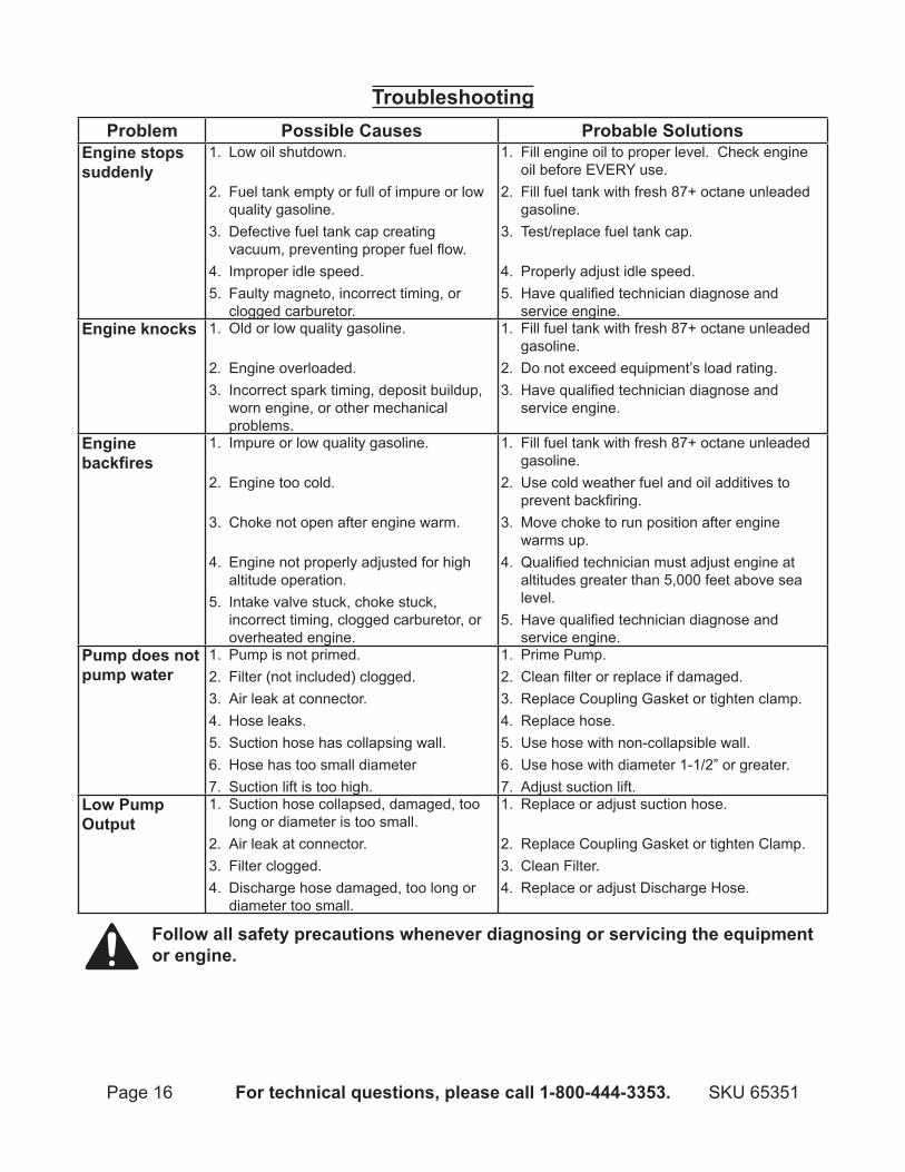
TroubleshootingProblem Possible Causes Probable Solutions
Engine stops suddenly
Low oil shutdown. 1.
Fuel tank empty or full of impure or low 2. quality gasoline.Defective fuel tank cap creating 3. vacuum, preventing proper fuel flow.Improper idle speed.4. Faulty magneto, incorrect timing, or 5. clogged carburetor.
Fill engine oil to proper level. Check engine 1. oil before EVERY use.Fill fuel tank with fresh 87+ octane unleaded 2. gasoline.Test/replace fuel tank cap. 3.
Properly adjust idle speed.4. Have qualified technician diagnose and 5. service engine.
Engine knocks Old or low quality gasoline. 1.
Engine overloaded.2. Incorrect spark timing, deposit buildup, 3. worn engine, or other mechanical problems.
Fill fuel tank with fresh 87+ octane unleaded 1. gasoline.Do not exceed equipment’s load rating.2. Have qualified technician diagnose and 3. service engine.
Engine backfires
Impure or low quality gasoline. 1.
Engine too cold. 2.
Choke not open after engine warm. 3.
Engine not properly adjusted for high 4. altitude operation.Intake valve stuck, choke stuck, 5. incorrect timing, clogged carburetor, or overheated engine.
Fill fuel tank with fresh 87+ octane unleaded 1. gasoline.Use cold weather fuel and oil additives to 2. prevent backfiring.Move choke to run position after engine 3. warms up.Qualified technician must adjust engine at 4. altitudes greater than 5,000 feet above sea level.Have qualified technician diagnose and 5. service engine.
Pump does not pump water
Pump is not primed.1. Filter (not included) clogged.2. Air leak at connector.3. Hose leaks.4. Suction hose has collapsing wall.5. Hose has too small diameter6. Suction lift is too high.7.
Prime Pump.1. Clean filter or replace if damaged.2. Replace Coupling Gasket or tighten clamp.3. Replace hose.4. Use hose with non-collapsible wall.5. Use hose with diameter 1-1/2” or greater.6. Adjust suction lift.7.
Low Pump Output
Suction hose collapsed, damaged, too 1. long or diameter is too small.Air leak at connector.2. Filter clogged.3. Discharge hose damaged, too long or 4. diameter too small.
Replace or adjust suction hose. 1.
Replace Coupling Gasket or tighten Clamp.2. Clean Filter.3. Replace or adjust Discharge Hose.4.
Follow all safety precautions whenever diagnosing or servicing the equipment or engine.
Page 17For technical questions, please call 1-800-444-3353.SKU 65351
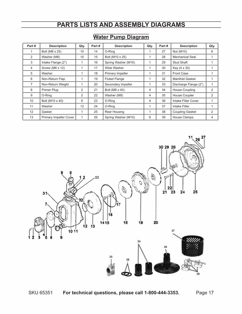
PARTS LISTS And ASSEMBLy dIAGRAMS
Water Pump diagramPart # description qty. Part # description qty. Part # description qty.
1 Bolt (M8 x 25) 10 14 O-Ring 1 27 Nut (M10) 6
2 Washer (M8) 10 15 Bolt (M10 x 25) 1 28 Mechanical Seal 1
3 Intake Flange (2”) 1 16 Spring Washer (M10) 1 29 Stud Shaft 1
4 Screw (M6 x 12) 1 17 Wide Washer 1 30 Key (4 x 35) 1
5 Washer 1 18 Primary Impeller 1 31 Front Case 1
6 Non-Return Flap 1 19 Fluted Flange 1 32 Manifold Gasket 1
7 Non-Return Weight 1 20 Secondary Impeller 1 33 Discharge Flange (2”) 1
8 Primer Plug 2 21 Bolt (M8 x 40) 4 34 House Coupling 2
9 O-Ring 2 22 Washer (M8) 4 35 House Coupler 2
10 Bolt (M10 x 40) 6 23 O-Ring 4 36 Intake Filter Cover 1
11 Washer 12 24 O-Ring 1 37 Intake Filter 1
12 Gasket 1 25 Rear Housing 1 38 Coupling Gasket 2
13 Primary Impeller Cover 1 26 Spring Washer (M10) 6 39 House Clamps 4
33
38
34
37
36
39
35
Page 18 For technical questions, please call 1-800-444-3353. SKU 65351
PLEASE REAd THE FOLLOWInG CAREFULLyTHE MANUFACTURER AND/OR DISTRIBUTOR HAS PROVIDED THE PARTS LIST AND ASSEMBLY DIAGRAM IN THIS MANUAL AS A REFERENCE TOOL ONLY. NEITHER THE MANUFACTURER OR DISTRIBUTOR MAKES ANY REPRESENTATION OR WARRANTY OF ANY KIND TO THE BUYER THAT HE OR SHE IS QUALIFIED TO MAKE ANY REPAIRS TO THE PRODUCT, OR THAT HE OR SHE IS QUALIFIED TO REPLACE ANY PARTS OF THE PRODUCT. IN FACT, THE MANUFACTURER AND/OR DISTRIBUTOR ExPRESSLY STATES THAT ALL REPAIRS AND PARTS REPLACEMENTS SHOULD BE UNDERTAKEN BY CERTIFIED AND LICENSED TECHNICIANS, AND NOT BY THE BUYER. THE BUYER ASSUMES ALL RISK AND LIABILITY ARISING OUT OF HIS OR HER REPAIRS TO THE ORIGINAL PRODUCT OR REPLACEMENT PARTS THERETO, OR ARISING OUT OF HIS OR HER INSTALLATION OF REPLACEMENT PARTS THERETO.
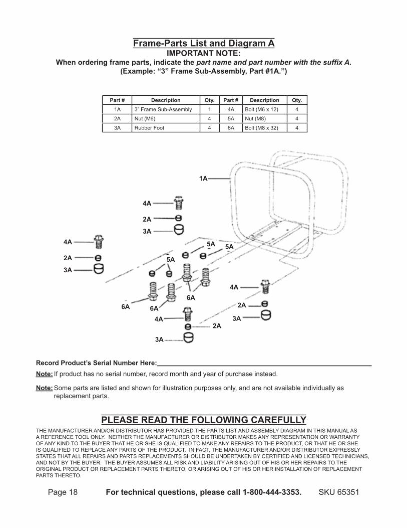
Frame-Parts List and diagram AIMPORTAnT nOTE:
When ordering frame parts, indicate the part name and part number with the suffix A.(Example: “3” Frame Sub-Assembly, Part #1A.”)
Part # description qty. Part # description qty.1A 3” Frame Sub-Assembly 1 4A Bolt (M6 x 12) 4
2A Nut (M6) 4 5A Nut (M8) 4
3A Rubber Foot 4 6A Bolt (M8 x 32) 4
4A 2A 3A
4A 2A 3A
1A
6A
3A
2A
4A
2A
3A
6A 6A
4A
5A
5A 5A
Record Product’s Serial number Here: note: If product has no serial number, record month and year of purchase instead.
note: Some parts are listed and shown for illustration purposes only, and are not available individually as replacement parts.
Page 19For technical questions, please call 1-800-444-3353.SKU 65351
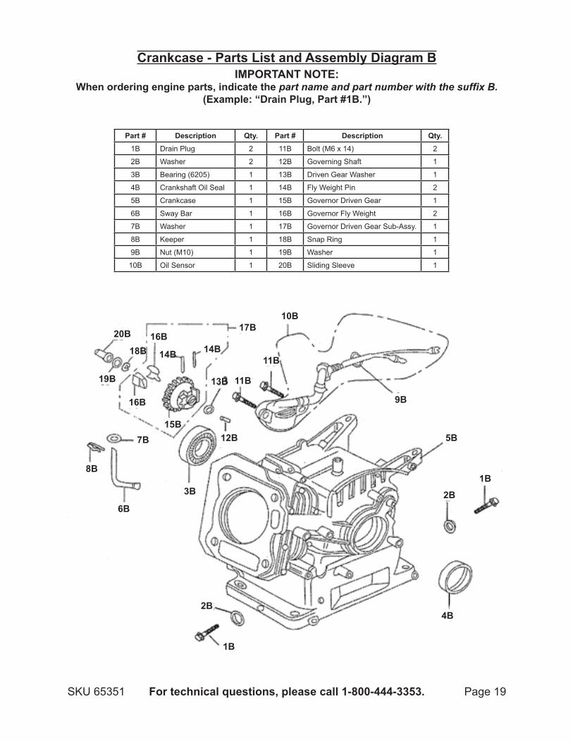
Crankcase - Parts List and Assembly diagram B
Part # description qty. Part # description qty.1B Drain Plug 2 11B Bolt (M6 x 14) 2
2B Washer 2 12B Governing Shaft 1
3B Bearing (6205) 1 13B Driven Gear Washer 1
4B Crankshaft Oil Seal 1 14B Fly Weight Pin 2
5B Crankcase 1 15B Governor Driven Gear 1
6B Sway Bar 1 16B Governor Fly Weight 2
7B Washer 1 17B Governor Driven Gear Sub-Assy. 1
8B Keeper 1 18B Snap Ring 1
9B Nut (M10) 1 19B Washer 1
10B Oil Sensor 1 20B Sliding Sleeve 1
IMPORTAnT nOTE:When ordering engine parts, indicate the part name and part number with the suffix B.
(Example: “Drain Plug, Part #1B.”)
1B
2B
2B
4B
1B
5B
6B
3B
8B
7B 12B
9B
10B
11B
11B
17B
13B
14B
15B
16B
16B
14B
20B
19B
18B
Page 20 For technical questions, please call 1-800-444-3353. SKU 65351
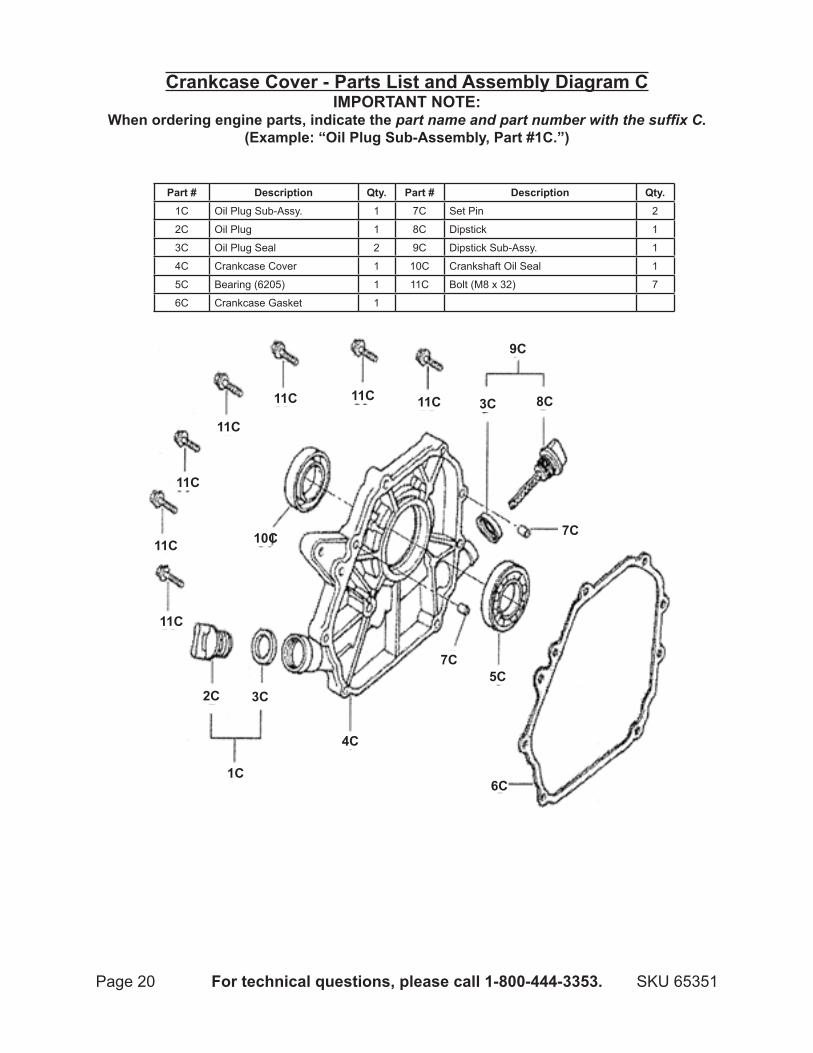
Crankcase Cover - Parts List and Assembly diagram CIMPORTAnT nOTE:
When ordering engine parts, indicate the part name and part number with the suffix C.(Example: “Oil Plug Sub-Assembly, Part #1C.”)
Part # description qty. Part # description qty.1C Oil Plug Sub-Assy. 1 7C Set Pin 2
2C Oil Plug 1 8C Dipstick 1
3C Oil Plug Seal 2 9C Dipstick Sub-Assy. 1
4C Crankcase Cover 1 10C Crankshaft Oil Seal 1
5C Bearing (6205) 1 11C Bolt (M8 x 32) 7
6C Crankcase Gasket 1
1C
2C 3C
4C
5C
6C
7C
7C
8C3C
9C
10C
11C
11C
11C
11C
11C 11C 11C
Page 21For technical questions, please call 1-800-444-3353.SKU 65351
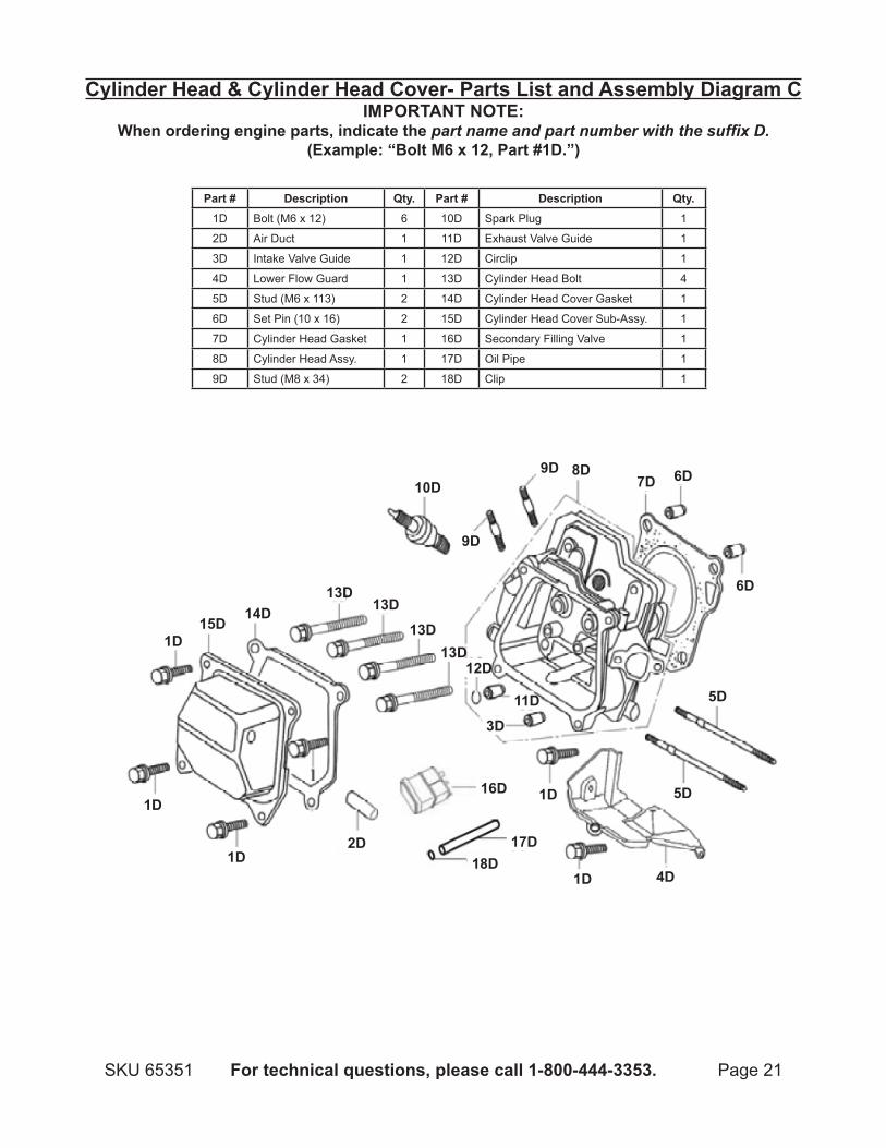
Cylinder Head & Cylinder Head Cover- Parts List and Assembly diagram CIMPORTAnT nOTE:
When ordering engine parts, indicate the part name and part number with the suffix D.(Example: “Bolt m6 x 12, Part #1D.”)
Part # description qty. Part # description qty.1D Bolt (M6 x 12) 6 10D Spark Plug 1
2D Air Duct 1 11D Exhaust Valve Guide 1
3D Intake Valve Guide 1 12D Circlip 1
4D Lower Flow Guard 1 13D Cylinder Head Bolt 4
5D Stud (M6 x 113) 2 14D Cylinder Head Cover Gasket 1
6D Set Pin (10 x 16) 2 15D Cylinder Head Cover Sub-Assy. 1
7D Cylinder Head Gasket 1 16D Secondary Filling Valve 1
8D Cylinder Head Assy. 1 17D Oil Pipe 1
9D Stud (M8 x 34) 2 18D Clip 1
1d
1d
1d 2d
1d
1d 4d
5d
5d
6d
6d7D8d9d
9d
10d
15d14d
13d13d
13d13d
3d11d
12d
16d
17D18d
Page 22 For technical questions, please call 1-800-444-3353. SKU 65351
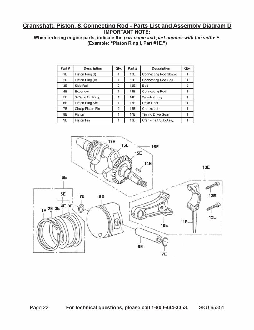
Crankshaft, Piston, & Connecting Rod - Parts List and Assembly diagram dIMPORTAnT nOTE:
When ordering engine parts, indicate the part name and part number with the suffix E.(Example: “Piston Ring I, Part #1E.”)
Part # description qty. Part # description qty.1E Piston Ring (I) 1 10E Connecting Rod Shank 1
2E Piston Ring (II) 1 11E Connecting Rod Cap 1
3E Side Rail 2 12E Bolt 2
4E Expander 1 13E Connecting Rod 1
5E 3-Piece Oil Ring 1 14E Woodruff Key 1
6E Piston Ring Set 1 15E Drive Gear 1
7E Circlip Piston Pin 2 16E Crankshaft 1
8E Piston 1 17E Timing Drive Gear 1
9E Piston Pin 1 18E Crankshaft Sub-Assy. 1
1E 2E 3E 4E 3E
5E
6E
7E 8E
7E
9E
18E17E
16E
15E
14E13E
12E
12E11E
10E
Page 23For technical questions, please call 1-800-444-3353.SKU 65351
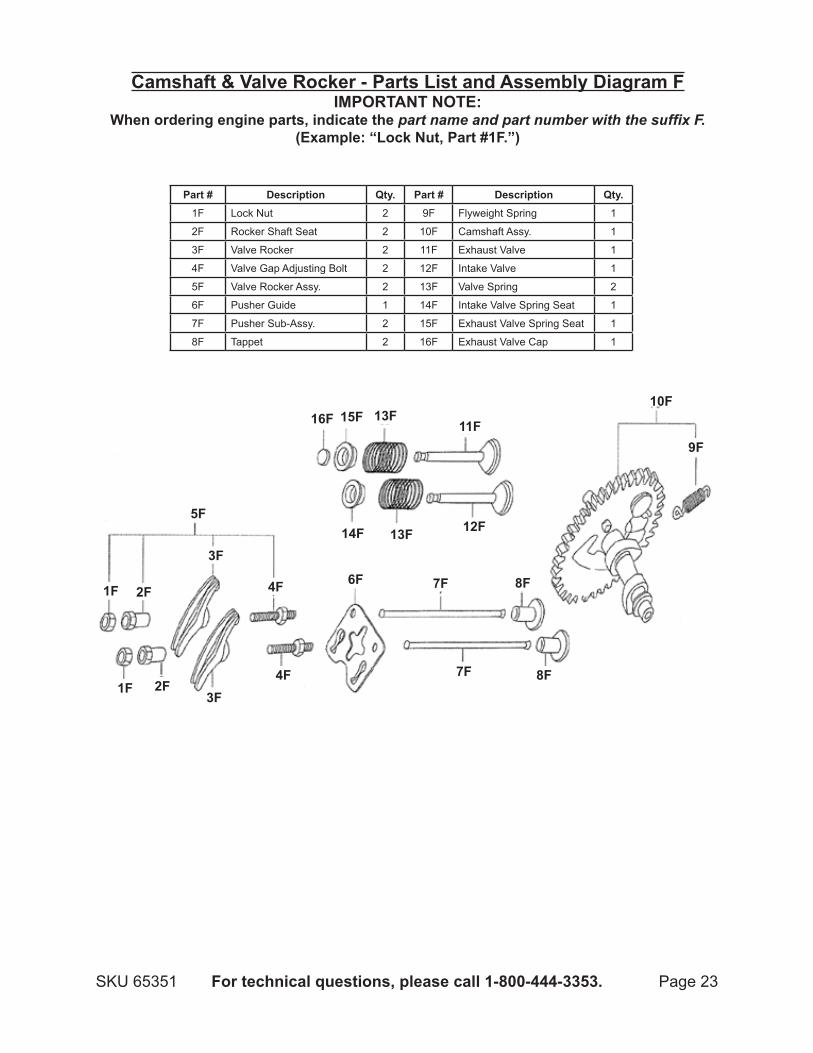
Camshaft & Valve Rocker - Parts List and Assembly diagram FIMPORTAnT nOTE:
When ordering engine parts, indicate the part name and part number with the suffix F.(Example: “Lock Nut, Part #1F.”)
Part # description qty. Part # description qty.1F Lock Nut 2 9F Flyweight Spring 1
2F Rocker Shaft Seat 2 10F Camshaft Assy. 1
3F Valve Rocker 2 11F Exhaust Valve 1
4F Valve Gap Adjusting Bolt 2 12F Intake Valve 1
5F Valve Rocker Assy. 2 13F Valve Spring 2
6F Pusher Guide 1 14F Intake Valve Spring Seat 1
7F Pusher Sub-Assy. 2 15F Exhaust Valve Spring Seat 1
8F Tappet 2 16F Exhaust Valve Cap 1
1F 2F3F
1F 2F
3F
4F
4F
5F
6F 7F
7F
8F
8F
9F
10F
11F
12F
13F
13F14F
15F16F
Page 24 For technical questions, please call 1-800-444-3353. SKU 65351
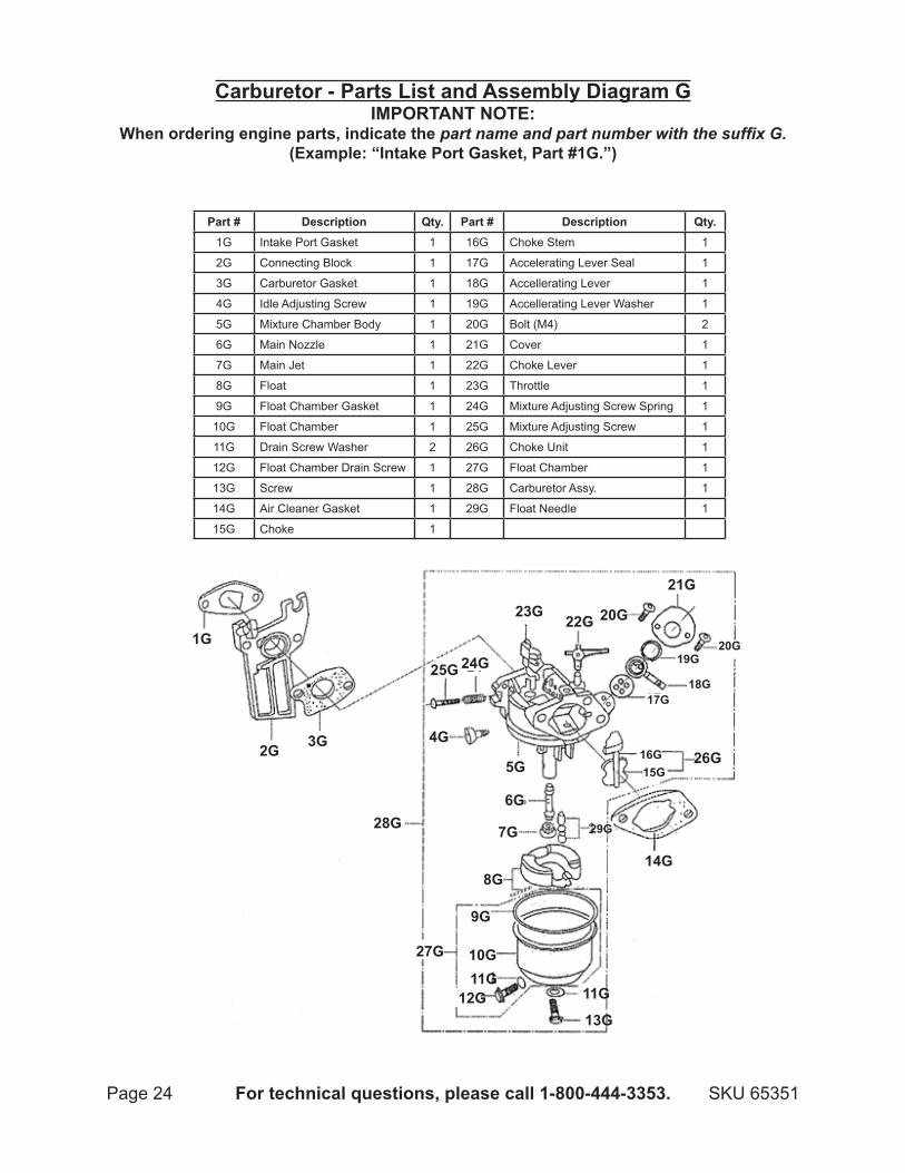
Carburetor - Parts List and Assembly diagram GIMPORTAnT nOTE:
When ordering engine parts, indicate the part name and part number with the suffix G.(Example: “Intake Port Gasket, Part #1G.”)
Part # description qty. Part # description qty.1G Intake Port Gasket 1 16G Choke Stem 1
2G Connecting Block 1 17G Accelerating Lever Seal 1
3G Carburetor Gasket 1 18G Accellerating Lever 1
4G Idle Adjusting Screw 1 19G Accellerating Lever Washer 1
5G Mixture Chamber Body 1 20G Bolt (M4) 2
6G Main Nozzle 1 21G Cover 1
7G Main Jet 1 22G Choke Lever 1
8G Float 1 23G Throttle 1
9G Float Chamber Gasket 1 24G Mixture Adjusting Screw Spring 1
10G Float Chamber 1 25G Mixture Adjusting Screw 1
11G Drain Screw Washer 2 26G Choke Unit 1
12G Float Chamber Drain Screw 1 27G Float Chamber 1
13G Screw 1 28G Carburetor Assy. 1
14G Air Cleaner Gasket 1 29G Float Needle 1
15G Choke 1
1G
2G 3G 4G
28G
5G
6G
7G
8G
9G
10G11G
12G 11G
13G
14G
27G
26G
25G 24G
29G
16G15G
17G
23G22G
21G
20G
18G
19G20G
Page 25For technical questions, please call 1-800-444-3353.SKU 65351
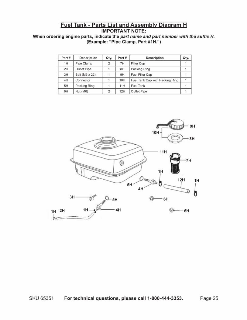
Fuel Tank - Parts List and Assembly diagram HIMPORTAnT nOTE:
When ordering engine parts, indicate the part name and part number with the suffix H.(Example: “Pipe Clamp, Part #1H.”)
Part # description qty. Part # description qty.1H Pipe Clamp 2 7H Filter Cup 1
2H Outlet Pipe 1 8H Packing Ring 1
3H Bolt (M6 x 22) 1 9H Fuel Filler Cap 1
4H Connector 1 10H Fuel Tank Cap with Packing Ring 1
5H Packing Ring 1 11H Fuel Tank 1
6H Nut (M6) 2 12H Outlet Pipe 1
8H 10H
9H
11H
7H
1H
1H
1H 1H
12H
6H
6H
4H 5H
5H
4H
3H
2H
Page 26 For technical questions, please call 1-800-444-3353. SKU 65351
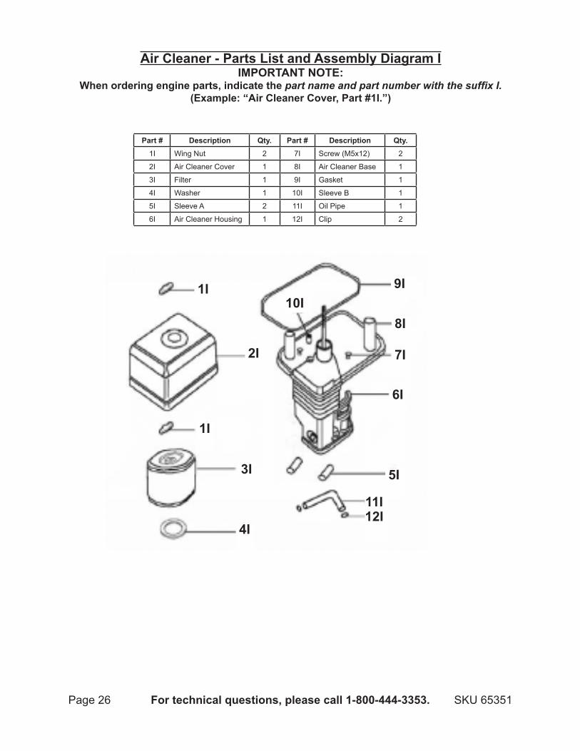
Air Cleaner - Parts List and Assembly diagram IIMPORTAnT nOTE:
When ordering engine parts, indicate the part name and part number with the suffix I.(Example: “Air Cleaner Cover, Part #1I.”)
Part # description qty. Part # description qty.1I Wing Nut 2 7I Screw (M5x12) 2
2I Air Cleaner Cover 1 8I Air Cleaner Base 1
3I Filter 1 9I Gasket 1
4I Washer 1 10I Sleeve B 1
5I Sleeve A 2 11I Oil Pipe 1
6I Air Cleaner Housing 1 12I Clip 2
1I
2I
6I
5I
10I
1I
3I
4I
7I
8I
9I
11I12I
Page 27For technical questions, please call 1-800-444-3353.SKU 65351
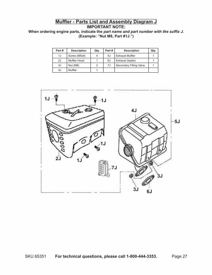
muffler - Parts List and Assembly Diagram JIMPORTAnT nOTE:
When ordering engine parts, indicate the part name and part number with the suffix J.(Example: “Nut m8, Part #1J.”)
Part # description qty. Part # description qty.
1J Screw (M5x8) 4 5J Exhaust Muffler 1
2J Muffler Hood 1 6J Exhaust Gasket 1
3J Nut (M8) 2 7J Secondary Filling Valve 1
4J Muffler 1
1J1J
2J
3J
4J
5J
6J
7J1J
1J
3J
Page 28 For technical questions, please call 1-800-444-3353. SKU 65351
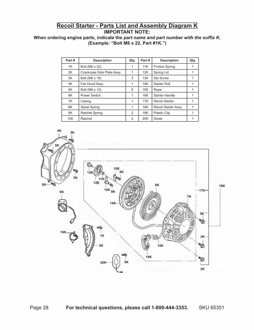
Recoil Starter - Parts List and Assembly diagram KIMPORTAnT nOTE:
When ordering engine parts, indicate the part name and part number with the suffix K.(Example: “Bolt m6 x 22, Part #1K.”)
Part # description qty. Part # description qty.
1K Bolt (M6 x 22) 1 11K Friction Spring 1
2K Crankcase Side Plate Assy. 1 12K Spring Lid 1
3K Bolt (M6 x 18) 3 13K Set Screw 1
4K Fan Hood Assy. 1 14K Starter Roll 1
5K Bolt (M6 x 12) 5 15K Rope 1
6K Power Switch 1 16K Starter Handle 1
7K Casing 1 17K Recoil Starter 1
8K Spiral Spring 1 18K Recoil Starter Assy. 1
9K Ratchet Spring 2 19K Plastic Clip 1
10K Ratchet 2 20K Diode 1
1K
2K
3K
3K
3K
4K
5K
5K
5K
5K
6K7K
8K
9K
9K10K
10K
12K
13K
15K
16K
18K
19K
20K
17K
5K
14K
11K
Page 29For technical questions, please call 1-800-444-3353.SKU 65351
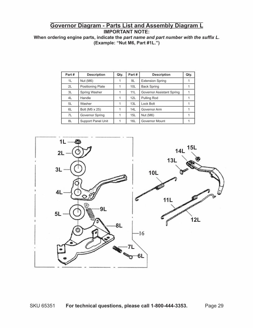
Governor diagram - Parts List and Assembly diagram LIMPORTAnT nOTE:
When ordering engine parts, indicate the part name and part number with the suffix L.(Example: “Nut m6, Part #1L.”)
Part # description qty. Part # description qty.
1L Nut (M6) 1 9L Extension Spring 1
2L Positioning Plate 1 10L Back Spring 1
3L Spring Washer 1 11L Governor Assistant Spring 1
4L Handle 1 12L Pulling Rod 1
5L Washer 1 13L Lock Bolt 1
6L Bolt (M5 x 25) 1 14L Governor Arm 1
7L Governor Spring 1 15L Nut (M6) 1
8L Support Panel Unit 1 16L Governor Mount 1
2L
1L
3L
4L
5L
6L7L
8L
9L
10L
11L
12L
13L14L 15L
Page 30 For technical questions, please call 1-800-444-3353. SKU 65351
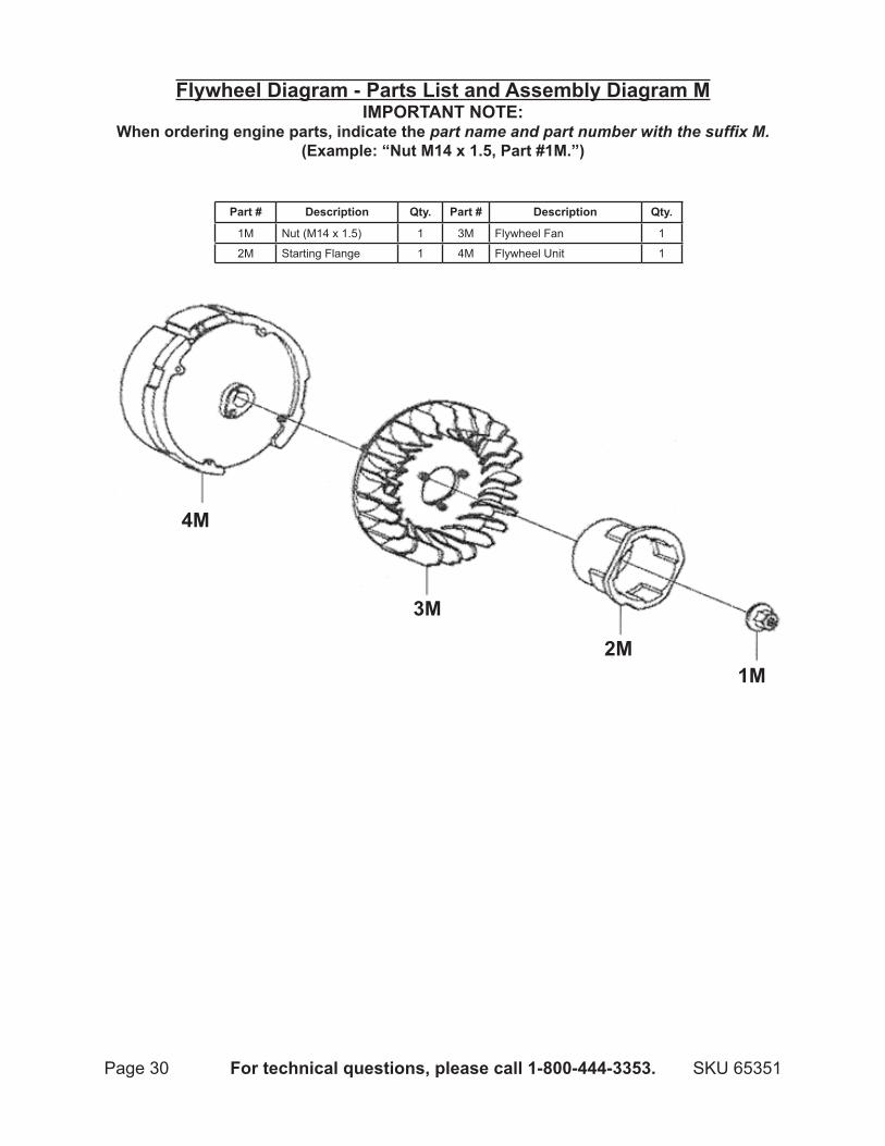
Flywheel diagram - Parts List and Assembly diagram MIMPORTAnT nOTE:
When ordering engine parts, indicate the part name and part number with the suffix M.(Example: “Nut m14 x 1.5, Part #1m.”)
Part # description qty. Part # description qty.
1M Nut (M14 x 1.5) 1 3M Flywheel Fan 1
2M Starting Flange 1 4M Flywheel Unit 1
1M2M
3M
4M

Page 31For technical questions, please call 1-800-444-3353.SKU 65351
Ignition Coil - Parts List and Assembly diagram nIMPORTAnT nOTE:
When ordering engine parts, indicate the part name and part number with the suffix N.(Example: “Bolt m6 x 25, Part #1N.”)
Part # description qty. Part # description qty.
1N Bolt (M6 x 25) 2 4N Spark Plug Cap 1
2N Engine Stop Cable 1 5N Ignition Coil Unit 1
3N Ignition Coil 1
1n
1n
2n
3n
4n
5n
Page 32 For technical questions, please call 1-800-444-3353. SKU 65351
LIMITEd 1 yEAR / 90 dAy WARRAnTy
Harbor Freight Tools Co. makes every effort to assure that its products meet high quality and durability standards, and warrants to the original purchaser that for a period of ninety days from date of purchase that the engine/motor, the belts (if so equipped), and the blades (if so equipped) are free of defects in materials and workmanship. Harbor Freight Tools also warrants to the original purchaser, for a period of one year from date of purchase, that all other parts and components of the product are free from defects in materials and workmanship (90 days if used by a professional contractor or if used as rental equipment). This warranty does not apply to damage due directly or indirectly, to misuse, abuse, negligence or accidents, repairs or alterations outside our facilities, normal wear and tear, or to lack of maintenance. We shall in no event be liable for death, injuries to persons or property, or for incidental, contingent, special or consequential damages arising from the use of our product. Some states do not allow the exclusion or limitation of incidental or consequential damages, so the above limitation of exclusion may not apply to you. THIS WARRANTY IS ExPRESSLY IN LIEU OF ALL OTHER WARRANTIES, ExPRESS OR IMPLIED, INCLUDING THE WARRANTIES OF MERCHANTABILITY AND FITNESS.
To take advantage of this warranty, the product or part must be returned to us with transportation charges prepaid. Proof of purchase date and an explanation of the complaint must accompany the merchandise. If our inspection verifies the defect, we will either repair or replace the product at our election or we may elect to refund the purchase price if we cannot readily and quickly provide you with a replacement. We
will return repaired products at our expense, but if we determine there is no defect, or that the defect resulted from causes not within the scope of our warranty, then you must bear the cost of returning the product.
This warranty gives you specific legal rights and you may also have other rights which vary from state to state.
3491 Mission Oaks Blvd. • PO Box 6009 • Camarillo, CA 93011 • (800) 444-3353
EMISSIOn COnTROL SySTEM WARRAnTy
California and United States Emission Control defects Warranty Statement
The California Air Resources Board (herein CARB), the United States Environmental Protection Agency (herein EPA), and Harbor Freight Tools (herein HFT) are pleased to explain the emission control system warranty on your 1995 and later Small Off-Road Engine (herein engine). In California, the engine must be designed, built and equipped to meet the State’s stringent anti-smog standards. Elsewhere within the United States, new off-road, spark-ignition engines certified for model year 1997 and later, must meet similar standards set forth by the EPA. HFT must warrant the emission control system on your engine for the periods of time described below, provided there has been no abuse, neglect or improper maintenance of your engine.
Your emission control system may include parts such as the carbu-retor or fuel-injection system, and the ignition system. Also included may be hoses, belts, connectors and other emission-related assemblies.
Where a warrantable condition exists, HFT will repair your engine at no cost to you including diagnosis, parts and labor.
Manufacturer’s Warranty CoverageThe 1995 and later engines are warranted for two (2) years. If
any emission-related part on your engine is defective, the part will be repaired or replaced by HFT.
Harbor Freight Tools Emission Control defects Warranty Coverage
Engines are warranted for a period of two (2) years relative to emission control parts defects, subject to the provisions set forth below. If any emission related part on your engine is defective, the part will be repaired or replaced by HFT.
Owner’s Warranty ResponsibilitiesAs the engine owner, you are responsible for the performance • of the required maintenance listed in your Owner’s Manual. HFT recommends that you retain all receipts covering maintenance on your engine, but HFT cannot deny warranty solely for the lack of receipts or for your failure to ensure the performance of all scheduled maintenance.As the engine owner, you should, however, be aware that HFT • may deny you warranty coverage if your engine or a part has failed due to abuse, neglect, improper maintenance, or unap-proved modifications.
Page 33For technical questions, please call 1-800-444-3353.SKU 65351
You are responsible for shipping your engine to a HFT warranty • station as soon as a problem exists. Contact the HFT Customer Service department at the number below to make shipping arrange-ments. The warranty repairs should be completed in a reasonable amount of time, not to exceed 30 days.
If you have any questions regarding your warranty rights and responsibilities, you should contact the Harbor Freight Tools Customer Service Department at 1-800-444-3353.
Harbor Freight Tools Emission Control defects Warranty Provisions
Length of CoverageHFT warrants to a first retail purchaser and each subsequent purchaser that the engine is free from defects in materials and workmanship that cause the failure of warranted parts for a period of two (2) years after the date of delivery to the first retail purchaser.
no Charge Repair or ReplacementRepair or replacement of any warranted part will be performed at no charge to the owner if the work is performed through a warranty station authorized by HFT. For emissions warranty service, contact the HFT Customer Service Department at 1-800-444-3353.
Consequential damages CoverageCoverage under this warranty shall also extend to the failure of any engine components caused by the failure of any warranted part while it is still covered under this warranty.
Coverage ExclusionsWarranty claims shall be filed in accordance with the provisions of the HFT warranty policy explained in the box at the top of the previous page. HFT shall not be liable for any loss of use of the engine, for any alternative usage, for any damage to goods, loss of time, or inconvenience. Warranty coverage shall also be excluded for any part which fails, malfunctions, or is damaged due to failure to follow the maintenance and operating instructions set forth in the Owner’s Manual including, but not limited to:
Use of parts which are not authorized by HFTa) Improper installation, adjustment or repair of the engine or b) of any warranted part unless performed by an authorized warranty centerFailure to follow recommendations on fuel use contained in c) the Owner’s ManualImproper or inadequate maintenance of any warranted d) partsRepairs performed outside of the authorized warranty service e) dealersAlterations by changing, adding to or removing parts from f) the engine.
Service and MaintenanceComponent parts which are not scheduled for replacement as required maintenance or are scheduled only for regular inspection to the effect of “repair or replace as necessary” are warranted for the warranty period. Any warranted part which is scheduled for replacement as required maintenance is warranted for the period of time up to the first scheduled replacement point for that part. Any replacement part, provided it is equivalent in durability and performance, may be used in performance of maintenance or repairs. The owner is responsible for commissioning a qualified technician/mechanic to perform all required maintenance, as outlined in the Inspection, Cleaning, and Maintenance section in this manual.
Warranted PartsFuel Metering System7)
Carburetor and its internal parts.i) Fuel pump (if so equipped).ii) Cold start enrichment system.iii)
Air Induction System8) Intake pipe/manifold.i) Air cleaner.ii)
Ignition System9) Spark plug.i) Magneto ignition system.ii)
Catalyst System (if so equipped)10) Exhaust pipe stud.i) Muffler.ii) Catalytic converter (if so equipped).iii)
Miscellaneous Items Used in Above Systems11) Vacuum, temperature and time sensitive valves and i) switches.Hoses, belts, connectors, and assemblies.ii)