Embed Size (px)
Citation preview

2. Feedlot site layout
AUTHOR: Peter Watts
FEEDLOT DESIGN AND CONSTRUCTION

2
FEEDLOT DESIGN AND CONSTRUCTION
2. Feedlot site layout
IntroductionThe principal objective of lot feeding cattle is to profitably produce beef of a specific, predictable and consistently repeatable quality for particular markets, both locally and overseas. Profitability is determined by • cattle performance and meat quality• the feedlot’s
– capital cost – operating cost – maintenance cost
However, the successful performance of a feedlot is now also measured by community acceptance. Thus it has to meet acceptable standards of• environmental impact• animal welfare• community amenity• workplace health and safety.
To meet these performance criteria, a feedlot must adopt a quality assurance program covering site selection, design, management and monitoring.
A feedlot is a production system incorporating several components that need to be carefully integrated. An overview of the various system components is given below. Detailed descriptions of the various components of a feedlot system are given in other sections.
This section describes the design of the overall layout of a feedlot to meet the profitability and community acceptance performance criteria.
Operational costs, including those of energy, have increased sharply in recent years while the availability of labour has declined.
Good site layout will integrate these components. If the layout is not ideal, components of the system can interfere, leading to operational inefficiencies.
Components of a feedlot system Feeding system Feed delivery, feed storage, silage pits, hay storage, feed processing mill, feed mixing/batching, feed trucks, feed alleys and feed bunks.
Watering system Water source, pumps and mainlines, emergency storage, pen reticulation system, water troughs and sewer system.
Cattle handling system Receival and induction facility, holding pens, cattle lanes, feeding pens, hospital pens, recovery pens and dispatch facilities.
Feeding system – storage, processing and delivery
Cattle handling systems – receival and induction, feeding pens and lanes

3
FEEDLOT DESIGN AND CONSTRUCTION
2. Feedlot site layout
Drainage system Feeding pens, pen drains, main drains, sedimentation systems, holding ponds and effluent utilisation areas.
Manure handling system Stockpile and manure screening area, pen manure cleaning equipment, manure composting and equipment, manure transport and processing equipment and manure utilisation areas.
Employee and visitor facilities Offices, amenities, lunch rooms, car parks, horse stables and workplace health and safety facilities.
Maintenance facilities Infrastructure for engineering, maintenance and repairs to equipment.
Security system Perimeter fencing, gates, lighting, signage and security cameras to provide biosecurity and security to the site.
Design objectivesThe design objectives for a feedlot site layout are to• maximise operational efficiency• maximise cattle performance• minimise environmental impact• minimise waste• maximise workplace health and safety• maximise cattle welfare• minimise capital and operational costs.
Specific design issues for consideration • Minimise travel distances and times for cattle, feed trucks and
manure equipment within the feedlot system.• Roads, drains and cattle lanes should not cross or traverse,
and there should be no gates in the feed alley or road network system.
• Separate cattle lanes and drains are preferable. When using a single cattle lane/pen drain it may be difficult to get cattle to walk through a wet and muddy drain and cattle may also bog-up the drain, reducing its effectiveness. Using the drain for the access of manure cleaning equipment can further damage it. (See Sections 10 and 16.)
• Avoid narrow cattle lanes, gateways, tight corners and turning circles to ensure efficient movement of cattle, feed trucks and manure cleaning equipment.
• Avoid narrow gates. The use of ‘herringbone’ type gates in cattle lanes enables excellent cattle flow in and out of the feeding pens while increasing turning circles for vehicle entry and exit. A single gate and a fixed opposing panel are adequate if cattle and manure equipment always move in one direction, but two gates are required if movement in both directions in the lane is envisaged. (See Section 16 – Fences, gates and lanes.)
Manure handling system – pen cleaning, manure composting and utilisation
Vehicles Crossing
Consider Intersection Design Looking at Number of Conflict Points
CROSS OVERINTERSECTION
'T' INTERSECTION
Vehicles Merging
Vehicles Diverging
16
8
8
Vehicles Diverging
Vehicles Merging
Vehicles Crossing
8.0m
8.0m
8.0m
3
3
3
Access road intersections
Wide lanes and gates
4
FEEDLOT DESIGN AND CONSTRUCTION
2. Feedlot site layout
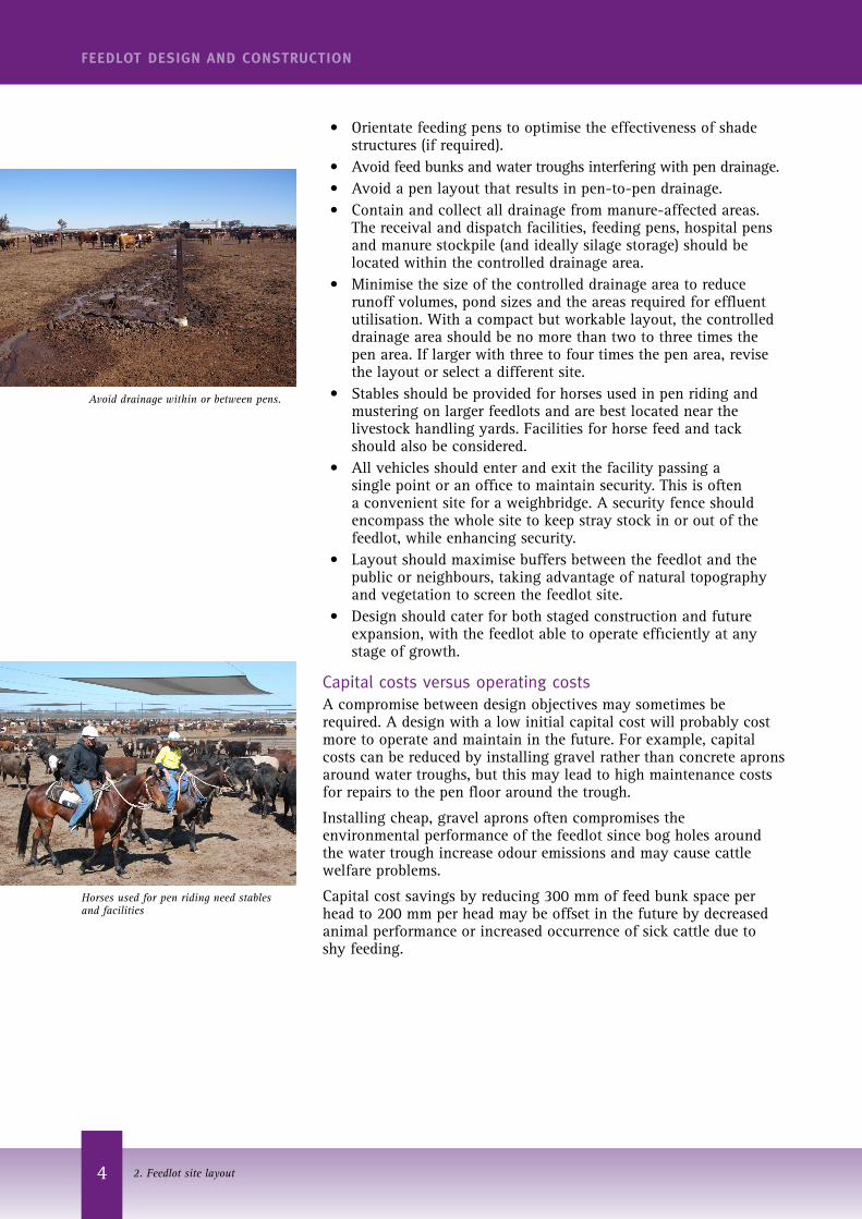
• Orientate feeding pens to optimise the effectiveness of shade structures (if required).
• Avoid feed bunks and water troughs interfering with pen drainage.• Avoid a pen layout that results in pen-to-pen drainage. • Contain and collect all drainage from manure-affected areas.
The receival and dispatch facilities, feeding pens, hospital pens and manure stockpile (and ideally silage storage) should be located within the controlled drainage area.
• Minimise the size of the controlled drainage area to reduce runoff volumes, pond sizes and the areas required for effluent utilisation. With a compact but workable layout, the controlled drainage area should be no more than two to three times the pen area. If larger with three to four times the pen area, revise the layout or select a different site.
• Stables should be provided for horses used in pen riding and mustering on larger feedlots and are best located near the livestock handling yards. Facilities for horse feed and tack should also be considered.
• All vehicles should enter and exit the facility passing a single point or an office to maintain security. This is often a convenient site for a weighbridge. A security fence should encompass the whole site to keep stray stock in or out of the feedlot, while enhancing security.
• Layout should maximise buffers between the feedlot and the public or neighbours, taking advantage of natural topography and vegetation to screen the feedlot site.
• Design should cater for both staged construction and future expansion, with the feedlot able to operate efficiently at any stage of growth.
Capital costs versus operating costsA compromise between design objectives may sometimes be required. A design with a low initial capital cost will probably cost more to operate and maintain in the future. For example, capital costs can be reduced by installing gravel rather than concrete aprons around water troughs, but this may lead to high maintenance costs for repairs to the pen floor around the trough.
Installing cheap, gravel aprons often compromises the environmental performance of the feedlot since bog holes around the water trough increase odour emissions and may cause cattle welfare problems.
Capital cost savings by reducing 300 mm of feed bunk space per head to 200 mm per head may be offset in the future by decreased animal performance or increased occurrence of sick cattle due to shy feeding.
Avoid drainage within or between pens.
Horses used for pen riding need stables and facilities

5
FEEDLOT DESIGN AND CONSTRUCTION
2. Feedlot site layout
Mandatory requirementsCompliance with:• Relevant Commonwealth, state and local authority codes,
regulations and relevant Australian standards as applicable to feedlot development.
• National Guidelines for Beef Cattle Feedlots in Australia (MLA, 2012a).
• National Beef Cattle Feedlot Environmental Code of Practice (MLA, 2012b).
Technical requirementsA wide range of information is needed before an appropriate design of feedlot layout can be proposed.
Information and data requirements
Site plans Aerial photographs, cadastral plans, road access, utilities.
Survey data Cadastral survey (e.g. boundary, easements), feature and topographic survey (e.g. utilities, natural/man-made features). See Section 7 for more detail on survey requirements.
Guidelines and Codes of Practice Relevant design criteria for feedlot layout elements.
Land resource data Overlays of soil types, vegetation, wetlands and natural features.
Topography and drainage Topographic data, overlays of watercourses and floodplains.
Separation distances Buffer distances from the feedlot complex to sensitive receptors including residences, portion boundaries, public roads, watercourses, bores and vegetation.
Visual impact Assessment of the visual impact of the site from neighbouring residences and public roads. “Out of sight, out of mind” is a benefit of good feedlot site layout.

6
FEEDLOT DESIGN AND CONSTRUCTION
2. Feedlot site layout
Design choicesFundamental design choices that will influence the overall layout include
Stocking densityStocking density has a significant influence on the environmental performance of a feedlot since it partly determines the average moisture content of the pad. Every day, cattle add moisture to the pen surface by depositing manure (faeces and urine).
The chosen stocking density that should achieve a balance between a pen surface that is, on average, too dry and one that is too wet depends on local climate and cattle size. (See Section 9 – Overall pen layout for more information on stocking density.)
The stocking density chosen will also determine the size and number of pens required and hence have a significant impact on construction and operational costs.
Feed bunk length per headFeed bunk length can vary from 200 mm/head to over 300 mm/head. The 300 mm bunk requires 50% more volume of concrete per head than the 200 mm bunk, and hence influences capital cost. Bunk length per head, along with stocking density, determines the width and depth of the pens.
(See Section 19 – Feeding systems for more information on bunk length per head.)
Pen capacitiesPen sizes in commercial feedlots may range from 50 head to 300 head. In custom feeding operations a variety of pen sizes allows management to cater optimally for different sized customer consignments.
When large consignments of cattle are fed long term, poor performers may be drafted off during the feeding period. These cattle may start in 300-head pens and some will end up in 50- and 100-head pens.
Many managers prefer a 100-head pen to finish cattle as this matches consignment sizes for transportation and container sizes for carcases and boxed beef. The smaller pens are generally located closer to the cattle receival and dispatch facilities.
(See Section 9 – Overall pen layout for more information on pen capacity.)
Pen and drain slopeGood pen drainage is essential to prevent odour problems and boggy pen conditions for the stock. Pen slopes can range from 2.5% to 6% but a gradient of 3–3.5% appears optimal. Slopes under 3% do not drain well, particularly if there is a buildup of manure.
Slopes over 4% can result in high rates of sediment removal during heavy storms particularly in deep pens or poorly cleaned pens, and this can cause problems throughout the whole of the drainage system.
The slope chosen may depend on site topography. For flat sites where earthworks are required to artificially create slope, lower
Feed bunk design, space per head and stock barriers
Stocking density and pen capacity

7
FEEDLOT DESIGN AND CONSTRUCTION
2. Feedlot site layout
pen slopes (2.5–3%) are often chosen. For steeper slopes such as hillsides, the natural topography usually determines the pen slope. In both cases, the orientation of the rows of pens should ensure adequate drain slope (0.5–1.5%).
(See Section 10 – Pen and drainage systems for more information on pen and drain slope.)
ShadeThe need for shade is determined by feedlot site, climatic conditions, cattle breeds and other factors. If shade will be installed the orientation of the pens becomes important, as the preferred orientation of the shade is north-south.
As the sun moves during the day, the shade available to the cattle moves across the width of the pen. An east-west orientation of shading prevents movement of the shaded area over the pen surface during the day and this can lead to localised buildup of moisture and manure under the shade structure.
(See Section 16 – Shade for more information on shade.)
On-site road systems The on-site road infrastructure is important to the overall layout. Factors such as the pitch, gradient and camber of roads affects vehicle stability, accurate feed delivery and road and vehicle damage over time.
Other factors include fitting the road to the natural contours of the land, road width, number of livestock lanes and feed truck turnarounds. The practicalities of feedlot access and safety also need to be considered. (See Section 13 – Access and internal roads for more information.)
Arrangement of facilitiesThere was a tendency to group the key feedlot facilities, particularly feed storage and preparation, cattle handling and the office, at one site in the middle of the feedlot but experience has shown that this arrangement rarely results in optimal functional performance. The preferred arrangement of facilities is to separate these three main systems.
All incoming and outgoing vehicles should travel past a single point or the main office where a truck weighbridge is located. This provides security and control over site entry as well as improved inventory control.
After passing the office, vehicles travel to either the feed receival/processing area or to the cattle receival/dispatch area. The cattle handling and feeding systems can be managed separately and both operate fairly independently with little operational interference. The practical examples of site layouts that follow demonstrate this independence.
Shade – orientation, shape and material

8
FEEDLOT DESIGN AND CONSTRUCTION
2. Feedlot site layout
Feeding pen configurationsFeeding pens are typically grouped into rows, usually with• Back-to-back configuration with a central feed alley servicing
pens on both sides of the roadway. Both sets of pens drain away from the feed alley to a stock alley or effluent drain.
• Sawtooth configuration with the feed alley servicing a single row of pens falling away from the road to a cattle lane or effluent drain.
Back-to-back configurations are probably more efficient in terms of feed delivery, time and fuel usage, but are generally suited only to relatively flat sites (<2%). Sawtooth layouts are the only cost-effective layouts for steeper sites (>2%) where the pen slope matches the natural slope.
Pen rows should be straight. Curved rows were once advocated as this suited a curved hillside. However, pen dimensions and bunk length per head are rarely uniform in these layouts, and it is difficult to deliver feed to a curved feed bunk without feed spillage and/or damage to the bunk due to collisions with feed trucks.
Basic layout choicesThe following practical examples show feedlot layouts for large and small feedlots that follow the design principles outlined above.• Feeding pen rows should be straight.• Pen rows should be either back-to-back configuration or
sawtooth configuration.• Feeding, cattle handling, manure removal and drainage systems
should be independent.• Feed roadways should not cross cattle lanes or drains.• The controlled drainage area should be as compact as possible.• Visitors, commodity, cattle and manure trucks should enter and
leave the site via a single entry/exit point or by passing the office/weighbridge.
Examples of overall layout
Overall site layout: All vehicles enter from the lower left
of the photograph. After going past the office, cattle trucks turn to the left while feed delivery trucks continue straight on.

9
FEEDLOT DESIGN AND CONSTRUCTION
2. Feedlot site layout
Small-size feedlot. Conceptual layout with single row of feeding pens.
Small feedlot with single row of equal-sized pens. This layout has sufficient area for expansion.
Medium-sized feedlot. Conceptual layout with back-to-back pen configuration.
10
FEEDLOT DESIGN AND CONSTRUCTION
2. Feedlot site layout
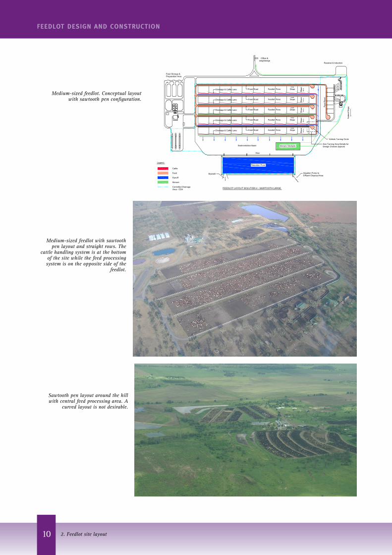
Medium-sized feedlot. Conceptual layout with sawtooth pen configuration.
Medium-sized feedlot with sawtooth pen layout and straight rows. The
cattle handling system is at the bottom of the site while the feed processing system is on the opposite side of the
feedlot.
Sawtooth pen layout around the hill with central feed processing area. A
curved layout is not desirable.

11
FEEDLOT DESIGN AND CONSTRUCTION
2. Feedlot site layout
Layout detailsSubsequent sections in this manual provide detail on most aspects of feedlot design. However, some details are specifically related to overall feedlot layout.
Long feed roadsIn some layouts, the rows of pens can become quite long (up to 1000 m). It is operationally inefficient for feed trucks to travel to the far end of each row if they are delivering feed only to the pens near the start of the row.
In addition to turning circles at the end of each feed road, turning circles can be installed in the middle of a row as it is generally unsafe to back feed trucks out of a feed road. Feed roads can be sealed with bitumen to minimise dust and damage to the feed truck. However, as a tight turning circle with a small mid-point can rapidly damage a bitumen surface, it can be left as compacted gravel.
Large-sized feedlot. Conceptual layout with back-to-back pen configuration.
Back-to-back straight rows with feed processing and cattle handling located on one side.
Curved feed roads and curved feed bunks should be avoided. Feed is often spilled and the bunks damaged by the feed truck.

12
FEEDLOT DESIGN AND CONSTRUCTION
2. Feedlot site layout
Use of areas adjacent to feed truck turning circlesAt the end of each feed row, there is a turning circle for feed trucks (assuming that the feed trucks do not cross cattle lanes) and this inevitably creates a space either side of the turning circle with a slope similar to that of the pen. This ‘vacant land’ could be used for hospitals, hospital pens, short production pens and/or road access for manure trucks. The following figures show options for the use of this ‘vacant land’ in back-to-back pen layouts.• Option A is a mid-lane turning circle for extended feeding
roadways.• Option B is a small production pen. This requires a bend in the
feed bunk.• Option C is a hospital treatment area.• Option D is vacant or green space.• Option E is an access point for manure trucks.
Option A – Mid-lane turning circle for extended roadways
Option A

13
FEEDLOT DESIGN AND CONSTRUCTION
2. Feedlot site layout
Feed Bunk
Feed Bunk
Hospital PensVehicle Turning Circle
Feed Truck Turning Path
Feed Road
Fenc
e
Fenc
e
Fenc
e
Feed Bunk
Feed Bunk
Production Pen
Vehicle Turning Circle
Feed Truck Turning Path
Feed Road
Fenc
eFe
nce
FEED TRUCK TURNING AREA OPTIONS
Manure truck movements
OPTION 'A'
OPTION 'B'
OPTION 'C'
OPTION 'D'
Runoff
Cattle Lane
Cattle Lane
Production Pen
Production Pen
Production Pen
Cat
tle L
ane
Cat
tle L
ane
Hospital
Manure TruckAccess toStockpile
Cattle Lane
Option B
Option C
Option D
Option E
Feed truck turning area options

14
FEEDLOT DESIGN AND CONSTRUCTION
2. Feedlot site layout
Manure truck accessAccess to a pen for pen cleaning and manure removal equipment is generally through the cattle lane and is facilitated by herringbone gates. However, adequate access is also required at both ends of the cattle lane.
Manure truck movement in cattle lanes is usually one way (i.e. the manure truck cannot turn around) and manure trucks need a swept entry/exit radius (appropriate to the size of vehicle), wider gates and a firm road base when exiting loaded.
Adequate access means entry/exit road slopes that are trafficable by fully-loaded manure trucks with sufficiently wide gates to allow turning of trucks (and trailers if attached).
Gates in feed bunksIn the past, some feedlots have installed gates into pens giving access from the feed road, but moving cattle to the cattle handling facility using the feed roads is not efficient practice. However, gates off the feed road do give pen access to pen cleaning and manure removal equipment without the need to use the cattle lane/drain. This may be a viable option for manure truck access in some configurations.
Gates at the top end of a cattle lane allow access for pen cleaning equipment and manure trucks
Gates giving vehicle and livestock access to pens from the feed alley
Further readingGuidelines for the establishment and operation of cattle feedlots in South Australia, Department of Primary Industries and Resources (SA) and Environment Protection Authority, 2006, Adelaide.
Guidelines for the Environmental Management of Beef Cattle Feedlots in Western Australia, Bulletin 4550, 2002, WADo Agriculture (ed.), Western Australia Department of Agriculture, Perth, WA.
National Guidelines for Beef Cattle Feedlots in Australia - 3rd Edition, Feedlot Industry Accreditation Committee (ed.), June 2012, Meat & Livestock Australia, Sydney, NSW.
National Beef Cattle Feedlot Environmental Code of Practice – 2nd Edition, Feedlot Industry Accreditation Committee (ed.), June 2012, Meat & Livestock Australia, Sydney, NSW.
Paine M, Teter, N and Guyer, P (n.d) ‘Feedlot Layout’, in Great Plains Beef Cattle Handbook, GPE-5201.
Skerman, A 2000, Reference manual for the establishment and operation of beef cattle feedlots in Queensland, Information Series QI99070, Queensland Cattle Feedlot Advisory Committee (FLAC), Department of Primary Industries, Toowoomba, QLD.
The New South Wales feedlot manual, 1997, NSW Agriculture, NSW Agriculture, Department of Land and Water Conservation, Department of Urban Affairs and Planning & Environment Protection Authority, Orange.
Victorian code for cattle feedlots, August 1995, Victorian Feedlot Commitee, Department of Agriculture, Energy & Minerals, Melbourne.