Embed Size (px)
Citation preview
2 EtherCAT Technology Group
© EtherCAT Technology Group. We reserve the right to make technical changes.
■ Content
3 Why EtherCAT?
4 User and Vendor Statements
6 EtherCAT Technology Group
8 EtherCAT – Technical Introduction and Overview
18 Implementation Aspects
23 Application Examples for Embedded Systems
24 Contact
3EtherCAT Technology Group
■ It’s faster| The fastest system available,
with outstanding synchronization features | Performance widely independent of topology| No underlying sub-system required any more| Meets today’s and tomorrow’s requirements
■ It’s cost effective| Meets or even undercuts fieldbus cost levels| No special master cards required –
on-board MAC or low cost standard NIC is fine| Highly integrated Slave Controllers for
lower interface costs| No active infrastructure components required
■ It’s easy to implement| Real-time protocol handling in hardware| Device application determines μC performance –
not the fieldbus protocol| Simple I/O slaves do not require μC at all| Universal slave interface modules available| Evaluation kits and stacks for master
and slave available
■ It’s easy to use| No manual address setting| No switch configuration| Auto configuration features| Diagnosis with exact localization
■ It’s flexible topology| All topologies supported: line, tree, star, ring| No node, switch or hub cascading issues| Up to 65,535 nodes per segment| Redundancy, Hot Connect, Hot Swap options
■ It’s versatile| master-slave, slave-slave and
master-master communication| Cyclic and acyclic services for process data
and parameter data| Suitable for centralized and distributed control
architectures| Machine control, robotics, embedded systems,
building automation, transport systems, …
■ It’s Industrial Ethernet| Standard Ethernet frames used| Supports all Internet technologies| HTTP, FTP, TCP/IP – without degrading
the real-time behavior| Simplifies vertical integration
■ It’s Safety on Ethernet| Functional Safety and standard application
with one network| Safety Protocol according to international
safety standard IEC 61508| Suitable for safety I/O and safety drives| Routable via gateways and fieldbus systems
■ It’s open| Open Technology, fully disclosed| Supported by the worlds largest Industrial
Ethernet Organization| EtherCAT is IEC, ISO and SEMI standard| Supports well established device profiles
■ It’s well proven| Deployed in series applications since 2003| Wide range of applications| Implemented on variety of controllers and
operating systems| Large product selection
© EtherCAT Technology Group. All rights reserved.
■ Why EtherCAT?
“The EtherCAT standard has potentialto be a significant and disruptive tech-nology in lowering costs and improvingperformance of hard real-time Ethernetbased fieldbus applications. As a 25-year
supplier of the RTOS iRMX and INtime for Windows TenAsys is par-ticularly aware of the highly optimized structure used in EtherCATtelegrams. We’re very pleased to be associated with the ETG, and inputting forth effort towards supplying a robust, and high perform-ance real-time EtherCAT master for OEM application.”
■ Martin Rostan, Head of TechnologyMarketing, Beckhoff Automation GmbH,and Executive Director,EtherCAT Technology Group:
“The strong growth of the EtherCAT Technology Groupreflects the tremendous worldwide interest in this exiting technology. Manufacturers and end users rec-
ognize the benefits: future-proof performance, flexible network topology, simpleconfiguration, and low costs. Nevertheless, while the number of members is animportant criterion for the success of a technology organization, it is not the cru-cial one. Acceptance of the technology resulting in product developments and ap-plications is even more important. Here too, EtherCAT is setting standards.”
■ Kenichi Karigane,General Manager,Drive Systems Division,Product Marketing & SalesEngineering Center,Hitachi IES Co., Ltd.:
“It is most important for us to supplycomponents and systems for factory automation that providebenefit and cover a wide range of application possibilities.Therefore, we have chosen EtherCAT from major Industrial Ether-net Solutions. We can expect that EtherCAT will contribute to thesuccess of our FA business because the technology provides highspeed and synchronization, good cost performance, and ETG main-tains an open door policy for product offering and supports ourproduct developments.“
■ Dieter Hess, ManagingDirector, 3S Smart SoftwareSolutions GmbH:
“3S decided to implement EtherCAT asthe first real-time Ethernet protocol,since EtherCAT utilizes the maximumperformance of Ethernet. For us as a
software manufacturer, the fact that the master implementationis independent of special plug-in cards is particularly attractive.The software can be based on the universally available standardEthernet controller. The openness of the system and active sup-port of Beckhoff for ETG are further significant factors.”
■ Kim Hartman, VP Sales & Marketing, TenAsys Corporation:
■ Dr. Peter Heidrich, R&D Manager,Baumüller GmbH, and ETG Board Member:
“Baumüller decided to use EtherCAT due to the signif-icant benefits it can offer, particularly in terms of pri-ce/performance ratio and availability. This decisionwas underlined through our active collaboration inthe ETG executive committee. We continue to be con-
vinced that the decision for EtherCAT was the right one. As soon as EtherCAT SlaveControllers became available, Baumüller started producing connections for thebmaXX 4400 system in August 2004. ETG has demonstrated that, due to the uni-versality of the EtherCAT technology, EtherCAT-based systems can be developedand realized very quickly.”
■ Erich Hutflesz, Manager Control Systems,Schuler SMG, and ETG Board Member:
“EtherCAT enables us to realize fast drive and hydrau-lic controls for all applications currently used in theSchuler Group. Another crucial factor is that, due toEtherCAT’s performance, we still have enough poten-tial for solving complex control tasks in future without
speed problems. Apart from the functional features of a technology, availabilityof a wide range of components is very significant for users of automation devices.The fact that so shortly after ETG was established so many member companieswere already presenting EtherCAT products and that further products are inpreparation is clear evidence for the success of this technology. The main factordetermining user acceptance continues to be simple and effective handling ofthe EtherCAT system in terms of configuration and diagnosis.”
4 EtherCAT Technology Group
© EtherCAT Technology Group. All rights reserved.
■ User and Vendor Statements
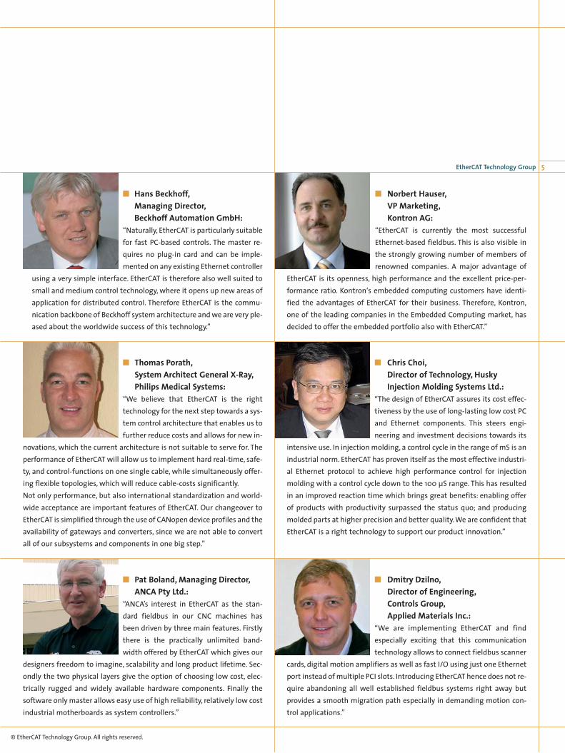
■ Norbert Hauser,VP Marketing,Kontron AG:
“EtherCAT is currently the most successful Ethernet-based fieldbus. This is also visible inthe strongly growing number of members ofrenowned companies. A major advantage of
EtherCAT is its openness, high performance and the excellent price-per-formance ratio. Kontron‘s embedded computing customers have identi-fied the advantages of EtherCAT for their business. Therefore, Kontron,one of the leading companies in the Embedded Computing market, hasdecided to offer the embedded portfolio also with EtherCAT.”
■ Thomas Porath,System Architect General X-Ray,Philips Medical Systems:
“We believe that EtherCAT is the righttechnology for the next step towards a sys-tem control architecture that enables us tofurther reduce costs and allows for new in-
novations, which the current architecture is not suitable to serve for. Theperformance of EtherCAT will allow us to implement hard real-time, safe-ty, and control-functions on one single cable, while simultaneously offer-ing flexible topologies, which will reduce cable-costs significantly.Not only performance, but also international standardization and world-wide acceptance are important features of EtherCAT. Our changeover toEtherCAT is simplified through the use of CANopen device profiles and theavailability of gateways and converters, since we are not able to convertall of our subsystems and components in one big step.”
■ Chris Choi,Director of Technology, Husky Injection Molding Systems Ltd.:
“The design of EtherCAT assures its cost effec-tiveness by the use of long-lasting low cost PCand Ethernet components. This steers engi-neering and investment decisions towards its
intensive use. In injection molding, a control cycle in the range of mS is anindustrial norm. EtherCAT has proven itself as the most effective industri-al Ethernet protocol to achieve high performance control for injectionmolding with a control cycle down to the 100 μS range. This has resultedin an improved reaction time which brings great benefits: enabling offerof products with productivity surpassed the status quo; and producingmolded parts at higher precision and better quality. We are confident thatEtherCAT is a right technology to support our product innovation.”
■ Pat Boland, Managing Director,ANCA Pty Ltd.:
“ANCA’s interest in EtherCAT as the stan-dard fieldbus in our CNC machines hasbeen driven by three main features. Firstlythere is the practically unlimited band-width offered by EtherCAT which gives our
designers freedom to imagine, scalability and long product lifetime. Sec-ondly the two physical layers give the option of choosing low cost, elec-trically rugged and widely available hardware components. Finally thesoftware only master allows easy use of high reliability, relatively low costindustrial motherboards as system controllers.”
5EtherCAT Technology Group
© EtherCAT Technology Group. All rights reserved.
■ Hans Beckhoff,Managing Director,Beckhoff Automation GmbH:
“Naturally, EtherCAT is particularly suitablefor fast PC-based controls. The master re-quires no plug-in card and can be imple-mented on any existing Ethernet controller
using a very simple interface. EtherCAT is therefore also well suited tosmall and medium control technology, where it opens up new areas ofapplication for distributed control. Therefore EtherCAT is the commu-nication backbone of Beckhoff system architecture and we are very ple-ased about the worldwide success of this technology.”
■ Dmitry Dzilno,Director of Engineering,Controls Group,Applied Materials Inc.:
“We are implementing EtherCAT and findespecially exciting that this communicationtechnology allows to connect fieldbus scanner
cards, digital motion amplifiers as well as fast I/O using just one Ethernetport instead of multiple PCI slots. Introducing EtherCAT hence does not re-quire abandoning all well established fieldbus systems right away butprovides a smooth migration path especially in demanding motion con-trol applications.”
The Management Board of the International Elec-trotechnical Commission (IEC) approved the Liaison of theEtherCAT Technology Group with the IEC Committee forDigital Communication: The ETG is official standardizationpartner organization.
Benefits of membership■ Member companies receive access to specificationdrafts, specifications, white papers, tools, prototype evalu-ation products and initial batch products and thus have a head start in evaluating, using or implementing theEtherCAT technology.■ Members are eligible to participate in working groupsand gain influence on future enhancements of the Ether-CAT technology specifications.■ ETG represent the member’s interest in internationalstandardization committees such as IEC and ISO.■ ETG members have access to the members-only part ofthe EtherCAT website, which provides specifications still indevelopment, a developers forum and up-to date informa-tion regarding the technology.
Everyone should be able to use and implement EtherCAT.The EtherCAT Technology Group stands for this philosophy.The ETG is a forum for end users from different sectors, andfor machine manufacturers and suppliers of powerful con-trol technology with the aim of supporting and promotingEtherCAT technology. The wide range of industry sectorsthat are represented ensures that EtherCAT is optimallyprepared for a large number of applications. With theirqualified feedback, the system partners ensure simple in-tegration of the hardware and software components in allrequired device classes.
The ETG Technical Committee meets frequently to re-view the technology. Technical Task Forces look after topicslike device profile integration, safety, wiring, standardiza-tion or test and certification.
In Training Classes and Seminars the ETG provides de-tailed information about the Technology. Plug Fests help toprovide interoperability and implementation support andcomplement the conformance test and certificationprocess.
6 EtherCAT Technology Group
© EtherCAT Technology Group. All rights reserved.
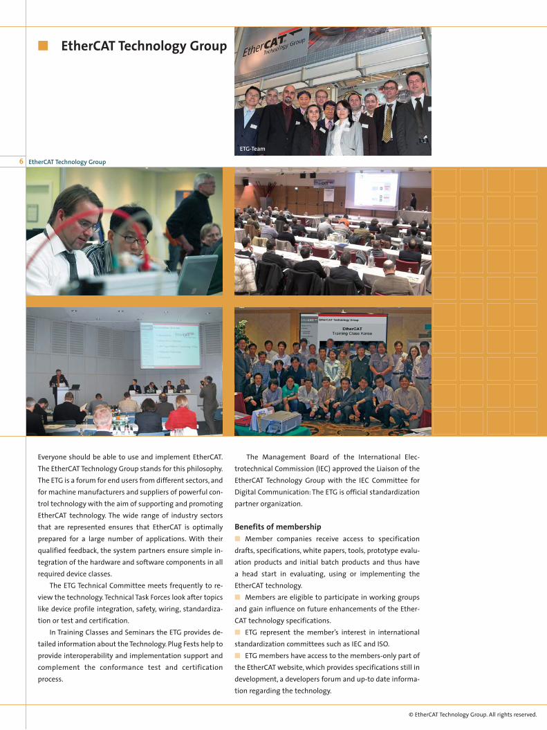
■ EtherCAT Technology Group
ETG-Team
7EtherCAT Technology Group
■ The ETG offices answers technical inquiries regardingEtherCAT, provide marketing assistance, publish productguides, issue press releases and articles, promote EtherCATvia its website and organize joint fair and exhibitionbooths.
International StandardizationThe EtherCAT specification is an international IEC and ISOstandard: EtherCAT is part of the international fieldbusstandard, IEC 61158 (Digital data communication for meas-urement and control – Fieldbus for use in industrial controlsystems). As part of the IEC 61784-2 (Industrial communi-cation networks – Part 2: Additional profiles for ISO/IEC 8802-3 based communication networks in real-timeapplications) profiles for specific EtherCAT device classesare defined.
The IEC 61800-7 is particularly important for MotionControl applications. The integration of EtherCAT in thisstandard makes it a standardized communication technol-ogy for the SERCOS™* and CANopen drive profiles.
Also the SEMI (Semiconductor Equipment and Materi-als International) has approved EtherCAT for their applica-tions by accepting the EtherCAT SEMI standard E54.20. Theleading standards organizations thus respond to the grow-ing interest of the industry in the fastest Industrial Ether-net solution.
Membership DevelopmentFounded in 2003, the EtherCAT Technology Group grew sofast that it can be considered the world’s largest IndustrialEthernet organization. With members from all over theworld and still growing, the ETG is a strong internationalcommunity. ETG offices in Europe, Asia and North Americaprovide support and members services. The current mem-bership list can be found on the EtherCAT website.
© EtherCAT Technology Group. All rights reserved.
“SERCOS Interface” is a trade name of SI e.V.
InputConversion
InputCommu-nication
Logic Calculation OutputConversion
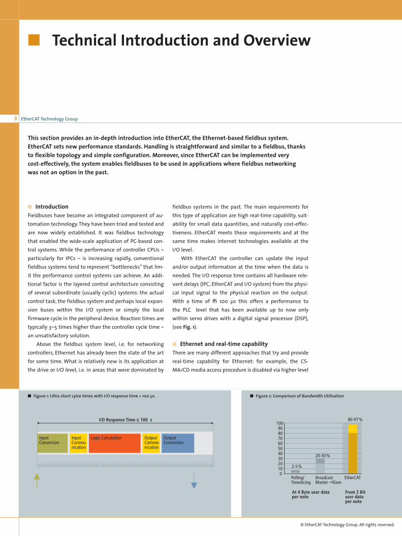
I/O Response Time 100 s
OutputCommu-nication
fieldbus systems in the past. The main requirements forthis type of application are high real-time capability, suit-ability for small data quantities, and naturally cost-effec-tiveness. EtherCAT meets these requirements and at thesame time makes internet technologies available at theI/O level.
With EtherCAT the controller can update the inputand/or output information at the time when the data isneeded. The I/O response time contains all hardware rele-vant delays (IPC, EtherCAT and I/O system) from the physi-cal input signal to the physical reaction on the output.With a time of ≤ 100 μs this offers a performance to the PLC level that has been available up to now only within servo drives with a digital signal processor (DSP),(see Fig. 1).
■ Ethernet and real-time capabilityThere are many different approaches that try and providereal-time capability for Ethernet: for example, the CS-MA/CD media access procedure is disabled via higher level
■ IntroductionFieldbuses have become an integrated component of au-tomation technology. They have been tried and tested andare now widely established. It was fieldbus technologythat enabled the wide-scale application of PC-based con-trol systems. While the performance of controller CPUs –particularly for IPCs – is increasing rapidly, conventionalfieldbus systems tend to represent “bottlenecks” that lim-it the performance control systems can achieve. An addi-tional factor is the layered control architecture consistingof several subordinate (usually cyclic) systems: the actualcontrol task, the fieldbus system and perhaps local expan-sion buses within the I/O system or simply the localfirmware cycle in the peripheral device. Reaction times aretypically 3–5 times higher than the controller cycle time –an unsatisfactory solution.
Above the fieldbus system level, i.e. for networkingcontrollers, Ethernet has already been the state of the artfor some time. What is relatively new is its application atthe drive or I/O level, i.e. in areas that were dominated by
8 EtherCAT Technology Group
© EtherCAT Technology Group. All rights reserved.
■ Technical Introduction and Overview
This section provides an in-depth introduction into EtherCAT, the Ethernet-based fieldbus system.EtherCAT sets new performance standards. Handling is straightforward and similar to a fieldbus, thanksto flexible topology and simple configuration. Moreover, since EtherCAT can be implemented very cost-effectively, the system enables fieldbuses to be used in applications where fieldbus networking was not an option in the past.
■ Figure 1: Ultra short cylce times with I/O response time < 100 μs
Polling/Timeslicing
0102030405060708090
100
2-5%
BroadcastMaster➝Slave
20-30%
EtherCAT
80-97%
At 4 Byte user dataper note
From 2 Bituser dataper note
■ Figure 2: Comparison of Bandwidth Utilisation
Ethernet Header ECAT HDR Datagram 1 Datagram 2 Datagram 3 Ethernet
Logical Process ImageTask 1
Logical Process ImageTask 2
Logical Process ImageTask 3
9EtherCAT Technology Group
protocol layers and replaced by the time slice procedure orpolling; other propositions use special switches that dis-tribute Ethernet packets in a precisely controlled timelymanner. Whilst these solutions may be able to transportdata packets more or less quickly and accurately to theconnected Ethernet nodes, the times required for the redi-rection to the outputs or drive controllers and for readingthe input data strongly depend on the implementation.
If individual Ethernet frames are used for each device,the usable data rate is very low in principle: The shortestEthernet frame is 84 bytes long (incl. inter-packet gap IPG).If, for example, a drive cyclically sends 4 bytes of actual val-ue and status information and accordingly receives 4 bytesof command value and control word information, at 100 %bus load (i.e. with infinitely short response time of thedrive) a usable data rate of only 4/84 = 4.8 % is achieved. Atan average response time of 10 μs, the rate drops to 1.9 %.These limitations apply to all real-time Ethernet approach-es that send an Ethernet frame to each device (or expect aframe from each device), irrespective of the protocols usedwithin the Ethernet frame.
■ EtherCAT operating principleEtherCAT technology overcomes these inherent limitationsof other Ethernet solutions: On the one hand the Ethernetpacket is no longer received then interpreted and processdata then copied at every device, but the EtherCAT slavedevices read the data addressed to them while the frame
© EtherCAT Technology Group. All rights reserved.
passes through the node. Similarly, input data is insertedwhile the telegram passes through (see Fig. 3). The framesare only delayed by a few nanoseconds. The frame send bythe master is passed through to the next device until itreaches the end of the segment (or branch). The last devicedetects an open port and therefore sends the frame backto the master.
On the other hand, an EtherCAT frame comprises thedata of many devices both in send and receive directionwithin one Ethernet frame. The usable data rate increasesto over 90 %. The full-duplex features of 100BaseTX are ful-ly utilized, so that effective data rates of > 100 Mb/s (> 90 %of 2 x 100 Mb/s) can be achieved (see Fig. 2).
The EtherCAT master uses standard Ethernet MediumAccess Controllers (MACs) without extra communicationprocessors. Thus an EtherCAT master can be implementedon any equipment controller that provides an Ethernet in-terface, independently of the operating system or applica-tion environment.
The EtherCAT slave uses an EtherCAT Slave Controller(ESC) for processing the data on-the-fly. Thus the perform-ance of the network is not determined by the microcon-troller performance of the slave but is handled complete inhardware. A process data interface (PDI) to the slave‘s ap-plication offers a Dual-Port-RAM for data exchange.
■ Figure 3: Process data is inserted in datagram
EtherCAT TelegramECATEthernet Header
DA SA Type Frame HDR Datagram 1 Datagram 2 -- Datagram n
(6)Ethertype 88A4h
(6) (2/4) (2) (10+n+2) (10+m+2) (10+k+2)
Ethernet
Pad. FCS
(0…32) (4)
EthernetHeader
IP Header UDP Header ECAT HDR EtherCAT Telegram
Ethertype 0800hUDP-Port: 88A4h
(20) (8)
Ethernet
10 EtherCAT Technology Group
© EtherCAT Technology Group. All rights reserved.
■ ProtocolEtherCAT only uses standard frames according to IEEE802.3 – the frames are not shortened. EtherCAT frames canthus be sent from any Ethernet controller (master), andstandard tools (e.g. monitor) can be used.
The EtherCAT protocol is optimized for process dataand is transported directly within the Ethernet framethanks to a special Ether type. It may consist of severalEtherCAT datagrams, each serving a particular memoryarea within the 4 gigabyte address space. This memory isavailable in the segment for process data and is used as adistributed memory. For small I/O devices the EtherCATSlave Controller also supports bitwise mapping. The bits ofan input device can be inserted individually anywherewithin the logical address space. If an EtherCAT datagramis sent that reads or writes a certain process image areathe input terminal inserts its data at the right place with-in the data area. This is done by the Fieldbus Memory Man-agement Unit (FMMU) within the ESC. So the data se-quence becomes independent of the physical order of theEthernet terminals in the network; addressing can be inany order. Broadcast, Multicast and communication be-tween slaves are possible. Direct Ethernet frame transfer isused in cases where maximum performance is requiredand the EtherCAT components are operated in the samesubnet as the controller.
However, EtherCAT applications are not limited to asingle subnet: EtherCAT UDP packages the EtherCAT proto-
■ Figure 4: EtherCAT: Standard Frames according to IEEE 802.3 [3]
col into UDP/IP datagrams (see Fig. 4). This enables anycontrol with Ethernet protocol stack to address EtherCATsystems. Even communication across routers into othersubnets is possible. In this variant, system performance ob-viously depends on the real-time characteristics of the con-trol and its Ethernet protocol implementation. The re-sponse times of the EtherCAT network itself are hardly re-stricted at all: the UDP datagram only has to be unpackedin the first station.
To access the local memory of the devices for examplefor configuration either the position of the devices in thesegment can be addressed or the device is addressed via anassigned fixed address.This means: No manual address ad-justment on the devices is needed!
The position addressing is used for the boot-up of thenetwork. The master can identify each device in the seg-ment (Vendor-ID, product code, etc.) and can read in thelink status of the device‘s ports. Therefore the complete in-formation about all devices and about the topology isavailable and can be compared to an expected configura-tion. Additionally, the master assigns a fixed address to alldevices.
This fixed address is used afterwards and addresses thedevices reliably even if one or more devices are not con-nected (e.g. Hot-plug groups) and therefore the position inthe segment is not the same.
In addition to data exchange according to the mas-ter/slave principle, EtherCAT is also very suitable for com-
■ Figure 5: Flexible Topology: Line, Tree or Star
11EtherCAT Technology Group
© EtherCAT Technology Group. All rights reserved.
Particularly useful for system wiring is the combina-tion of line and branches or stubs: the required interfacesexist on many devices (e.g. on I/O modules); no additionalswitches are required. Naturally, the classic switch-basedEthernet star topology can also be used.
Wiring flexibility is further maximized through thechoice of different cables. Flexible and inexpensive stan-dard Ethernet cables transfer the signals in 100BASE-TXmode. Plastic optical fibers (POF) will complement the sys-tem for special applications. The complete choice of Ether-net wiring – such as different optical fibers and copper ca-bles – can be used in combination with switches or mediaconverters.
The Fast Ethernet physics (100BASE-TX) enables a cablelength of 100 m between two devices. Since up to 65,535devices can be connected, the size of the network is almostunlimited.
The Ethernet protocol according to IEEE 802.3 remainsintact right up to the individual device; no sub-bus is re-quired. In order to meet the requirements of a modular de-vice like an electronic terminal block, the physical layer inthe coupling device can be converted from twisted pair oroptical fiber to LVDS (alternative Ethernet physical layer,standardized in [4,5]). A modular device can thus be ex-tended very cost-efficiently. Subsequent conversion fromthe backplane physical layer LVDS to the 100BASE-TX phys-ical layer is possible at any time – as usual with Ethernet.
munication between controllers (master/master). Freelyaddressable network variables for process data and a vari-ety of services for parameterization, diagnosis, program-ming and remote control cover a wide range of require-ments. The data interfaces for master/slave and mas-ter/master communication are identical.
For slave-to-slave communication, two mechanismsare available. Upstream devices can communicate todownstream devices within the same cycle – and thus ex-tremely fast. Since this method is topology-dependent, it isparticularly suitable for slave-to-slave communication re-lationships given by machine design – e.g. in printing orpackaging applications. For freely configurable slave-to-slave communication, the second mechanism applies: thedata is relayed by the master. Here, two cycles are needed,but due to the extraordinary performance of EtherCAT thisis still faster than any other approach.
EtherCAT only uses standard frames according to [3] –the frames are not shortened. EtherCAT frames can thus besent from any Ethernet MAC, and standard tools (e.g. mon-itor) can be used.
■ TopologyLine, tree or star: EtherCAT supports almost any topology(see Fig. 5). The bus or line structure known from the field-buses thus also becomes available for Ethernet, withoutthe quantity limitations implied by cascaded switches orhubs.
sssss s
sΔt
M■ Figure 6: Synchronicity and Simultaneousness: Scope view of two
distributed devices with 300 nodes and 120m of cable between them
12 EtherCAT Technology Group
© EtherCAT Technology Group. All rights reserved.
also provide accurate information about the local timingof the data acquisition. For example, motion controllerstypically calculate velocities from sequentially measuredpositions. Particularly with very short sampling times, evena small temporal jitter in the position measurement leadsto large step changes in the computed velocity.With Ether-CAT, timestamp data types are introduced as a logical ex-tension. The high resolution system time is linked to themeasured value, which is made possible by the large band-width offered by Ethernet. The accuracy of a velocity calcu-lation then no longer depends on the jitter of the commu-nication system. It is orders of magnitude better than thatof measuring techniques based on jitter-free communica-tion.
■ PerformanceEtherCAT reaches new dimensions in network perform-ance. Thanks to hardware integration in the slave and di-rect memory access to the network controller in the mas-ter, the complete protocol processing takes place withinhardware and is thus fully independent of the run-time ofprotocol stacks, CPU performance or software implemen-tation. The update time for 1,000 I/Os is only 30 μs – in-cluding I/O cycle time (see Table 1). Up to 1486 bytes ofprocess data can be exchanged with a single Ethernetframe – this is equivalent to almost 12,000 digital inputsand outputs. The transfer of this data quantity only takes150 μs. The communication with 100 servo axes is also ex-
■ Distributed clocksAccurate synchronization is particularly important in caseswhere spatially distributed processes require simultane-ous actions. This may be the case, for example, in applica-tions where several servo axes carry out coordinated move-ments simultaneously.
The most powerful approach for synchronization is theaccurate alignment of distributed clocks, as described forexample in the IEEE 1588 standard [6]. In contrast to fullysynchronous communication, where synchronization qual-ity suffers immediately in the event of a communicationfault, distributed aligned clocks have a high degree of tol-erance versus possible fault-related delays within the com-munication system.
With EtherCAT, the synchronization of the devices isfully based on a pure hardware machine. Since the com-munication utilizes a logical (and thanks to full-duplex FastEthernet also physical) ring structure, a timestamp can besampled within each device for the incoming and the re-turning frame. With these timestamps the master can de-termine the propagation delay offset to the individualslave clocks simply and accurately (see Fig. 7). The distrib-uted clocks are adjusted based on this value, which meansthat a very precise network-wide time base with a jitter ofsignificantly less then 1 microsecond is available (see Fig. 6). External synchronization, e.g. across the plant, isthen based on IEEE 1588. However, high-resolution distrib-uted clocks are not only used for synchronization, but can
■ Figure 7: Setting the indivual clocks of each device to the network-wide time base.
13EtherCAT Technology Group
consistency with the specified configuration. The topologyshould also match the configuration. Due to the built-intopology recognition down to the individual terminals,this verification can not only take place during systemstart-up, automatic reading in of the network is also possi-ble (configuration up-load).
Bit faults during the transfer are reliably detectedthrough evaluation of the CRC checksum: The 32 bit CRCpolynomial has a minimum hamming distance of 4. Apartfrom broken wire detection and localization, the protocol,physical layer and topology of the EtherCAT system enableindividual quality monitoring of each individual transmis-sion segment. The automatic evaluation of the associatederror counters enables precise localization of critical net-work sections. Gradual or changing sources of error such asEMI influences, defective connectors or cable damage aredetected and located, even if they do not yet overstrain theself healing capacity of the network.
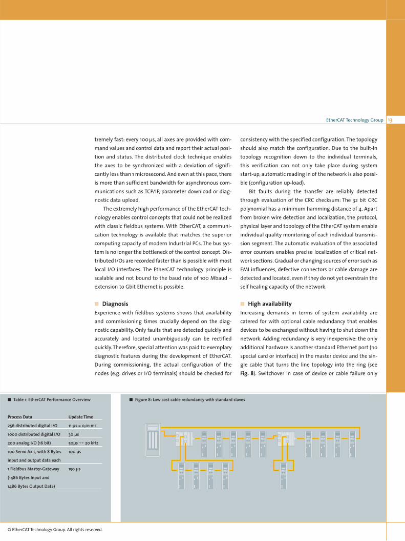
■ High availabilityIncreasing demands in terms of system availability arecatered for with optional cable redundancy that enablesdevices to be exchanged without having to shut down thenetwork. Adding redundancy is very inexpensive: the onlyadditional hardware is another standard Ethernet port (nospecial card or interface) in the master device and the sin-gle cable that turns the line topology into the ring (see Fig. 8). Switchover in case of device or cable failure only
© EtherCAT Technology Group. All rights reserved.
tremely fast: every 100 μs, all axes are provided with com-mand values and control data and report their actual posi-tion and status. The distributed clock technique enablesthe axes to be synchronized with a deviation of signifi-cantly less than 1 microsecond. And even at this pace, thereis more than sufficient bandwidth for asynchronous com-munications such as TCP/IP, parameter download or diag-nostic data upload.
The extremely high performance of the EtherCAT tech-nology enables control concepts that could not be realizedwith classic fieldbus systems. With EtherCAT, a communi-cation technology is available that matches the superiorcomputing capacity of modern Industrial PCs. The bus sys-tem is no longer the bottleneck of the control concept. Dis-tributed I/Os are recorded faster than is possible with mostlocal I/O interfaces. The EtherCAT technology principle isscalable and not bound to the baud rate of 100 Mbaud –extension to Gbit Ethernet is possible.
■ DiagnosisExperience with fieldbus systems shows that availabilityand commissioning times crucially depend on the diag-nostic capability. Only faults that are detected quickly andaccurately and located unambiguously can be rectifiedquickly. Therefore, special attention was paid to exemplarydiagnostic features during the development of EtherCAT.During commissioning, the actual configuration of thenodes (e.g. drives or I/O terminals) should be checked for
■ Table 1: EtherCAT Performance Overview
Process Data Update Time
256 distributed digital I/O 11 μs = 0,01 ms
1000 distributed digital I/O 30 μs
200 analog I/O (16 bit) 50μs ↔ 20 kHz
100 Servo Axis, with 8 Bytes 100 μs
input and output data each
1 Fieldbus Master-Gateway 150 μs
(1486 Bytes Input and
1486 Bytes Output Data)
■ Figure 8: Low cost cable redundancy with standard slaves
■ Figure 9: Decentralized Fieldbus Interfaces
takes one cycle, so even demanding motion control appli-cations survive a cable failure without problems. EtherCATalso supports redundant masters with hot standby func-tionality. Since the EtherCAT Slave Controllers immediatelyreturn the frame automatically if an interruption is en-countered, failure of a device does not necessarily lead tothe complete network being shut down. Drag chain appli-cations, for example, can thus be specifically configured asstubs in order to be prepared for cable break.
■ SafetyConventionally, safety functions are realized separatelyfrom the automation network, either via hardware or us-ing dedicated safety bus systems. Safety over EtherCAT en-ables safety-related communication and control communi-cation on the same network. The safety protocol is basedon the application layer of EtherCAT, without influencingthe lower layers. It is certified according to IEC 61508 andmeets the requirements of Safety Integrity Level (SIL) 3.Thedata length is variable, making the protocol equally suit-able for safe I/O data and for safe drive technology. Thereare no restrictions regarding the communication mediumor the transfer rate. Like other EtherCAT data, the safety da-ta can be routed without requiring safety routers or gate-ways. First fully certified products featuring Safety overEtherCAT are available since 2005.
14 EtherCAT Technology Group
© EtherCAT Technology Group. All rights reserved.
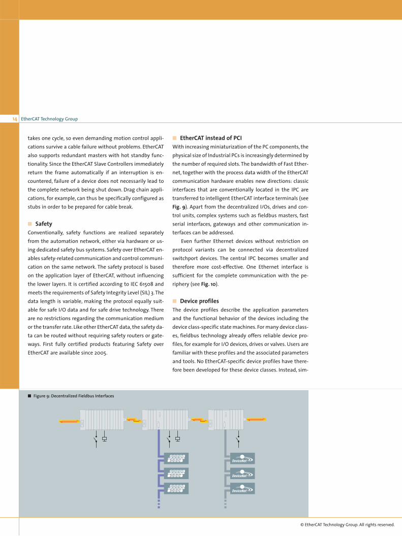
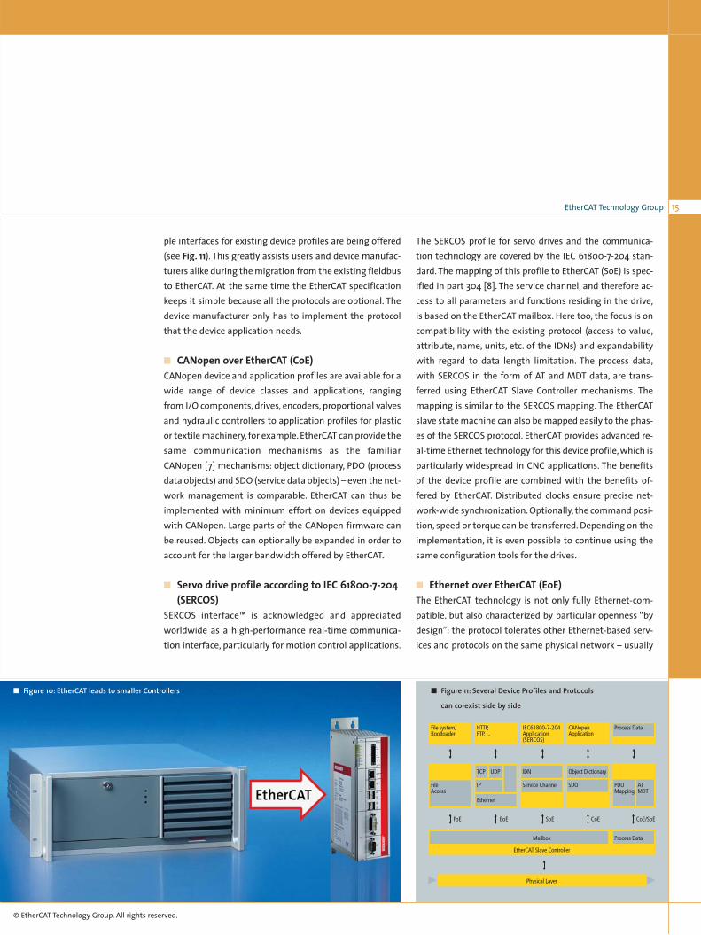
■ EtherCAT instead of PCIWith increasing miniaturization of the PC components, thephysical size of Industrial PCs is increasingly determined bythe number of required slots. The bandwidth of Fast Ether-net, together with the process data width of the EtherCATcommunication hardware enables new directions: classicinterfaces that are conventionally located in the IPC aretransferred to intelligent EtherCAT interface terminals (seeFig. 9). Apart from the decentralized I/Os, drives and con-trol units, complex systems such as fieldbus masters, fastserial interfaces, gateways and other communication in-terfaces can be addressed.
Even further Ethernet devices without restriction onprotocol variants can be connected via decentralizedswitchport devices. The central IPC becomes smaller andtherefore more cost-effective. One Ethernet interface issufficient for the complete communication with the pe-riphery (see Fig. 10).
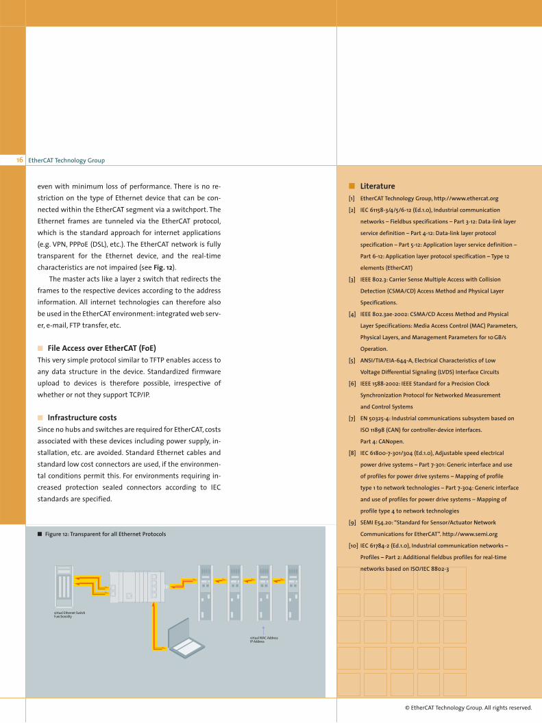
■ Device profilesThe device profiles describe the application parametersand the functional behavior of the devices including thedevice class-specific state machines. For many device class-es, fieldbus technology already offers reliable device pro-files, for example for I/O devices, drives or valves. Users arefamiliar with these profiles and the associated parametersand tools. No EtherCAT-specific device profiles have there-fore been developed for these device classes. Instead, sim-
PDOMapping
ATMDT
FileAccess
Mailbox
EtherCAT Slave Controller
Physical Layer
IDN
CANopenApplication
HTTP,FTP, ...
File system,Bootloader
Process Data
Object Dictionary
SDOIP
TCP
Ethernet
Service Channel
Process Data
UDP
FoE EoE SoE CoE CoE/SoE
IEC61800-7-204Application(SERCOS)
■ Figure 11: Several Device Profiles and Protocols
can co-exist side by side
15EtherCAT Technology Group
© EtherCAT Technology Group. All rights reserved.
ple interfaces for existing device profiles are being offered(see Fig. 11). This greatly assists users and device manufac-turers alike during the migration from the existing fieldbusto EtherCAT. At the same time the EtherCAT specificationkeeps it simple because all the protocols are optional. Thedevice manufacturer only has to implement the protocolthat the device application needs.
■ CANopen over EtherCAT (CoE)CANopen device and application profiles are available for awide range of device classes and applications, rangingfrom I/O components, drives, encoders, proportional valvesand hydraulic controllers to application profiles for plasticor textile machinery, for example. EtherCAT can provide thesame communication mechanisms as the familiarCANopen [7] mechanisms: object dictionary, PDO (processdata objects) and SDO (service data objects) – even the net-work management is comparable. EtherCAT can thus beimplemented with minimum effort on devices equippedwith CANopen. Large parts of the CANopen firmware canbe reused. Objects can optionally be expanded in order toaccount for the larger bandwidth offered by EtherCAT.
■ Servo drive profile according to IEC 61800-7-204 (SERCOS)
SERCOS interface™ is acknowledged and appreciatedworldwide as a high-performance real-time communica-tion interface, particularly for motion control applications.
The SERCOS profile for servo drives and the communica-tion technology are covered by the IEC 61800-7-204 stan-dard. The mapping of this profile to EtherCAT (SoE) is spec-ified in part 304 [8]. The service channel, and therefore ac-cess to all parameters and functions residing in the drive,is based on the EtherCAT mailbox. Here too, the focus is oncompatibility with the existing protocol (access to value,attribute, name, units, etc. of the IDNs) and expandabilitywith regard to data length limitation. The process data,with SERCOS in the form of AT and MDT data, are trans-ferred using EtherCAT Slave Controller mechanisms. Themapping is similar to the SERCOS mapping. The EtherCATslave state machine can also be mapped easily to the phas-es of the SERCOS protocol. EtherCAT provides advanced re-al-time Ethernet technology for this device profile, which isparticularly widespread in CNC applications. The benefitsof the device profile are combined with the benefits of-fered by EtherCAT. Distributed clocks ensure precise net-work-wide synchronization. Optionally, the command posi-tion, speed or torque can be transferred. Depending on theimplementation, it is even possible to continue using thesame configuration tools for the drives.
■ Ethernet over EtherCAT (EoE)The EtherCAT technology is not only fully Ethernet-com-patible, but also characterized by particular openness “bydesign”: the protocol tolerates other Ethernet-based serv-ices and protocols on the same physical network – usually
■ Figure 10: EtherCAT leads to smaller Controllers
virtual Ethernet SwitchFunctionality
virtual MAC AddressIP Address
■ Figure 12: Transparent for all Ethernet Protocols
even with minimum loss of performance. There is no re-striction on the type of Ethernet device that can be con-nected within the EtherCAT segment via a switchport. TheEthernet frames are tunneled via the EtherCAT protocol,which is the standard approach for internet applications(e.g. VPN, PPPoE (DSL), etc.). The EtherCAT network is fullytransparent for the Ethernet device, and the real-timecharacteristics are not impaired (see Fig. 12).
The master acts like a layer 2 switch that redirects theframes to the respective devices according to the addressinformation. All internet technologies can therefore alsobe used in the EtherCAT environment: integrated web serv-er, e-mail, FTP transfer, etc.
■ File Access over EtherCAT (FoE)This very simple protocol similar to TFTP enables access toany data structure in the device. Standardized firmwareupload to devices is therefore possible, irrespective ofwhether or not they support TCP/IP.
■ Infrastructure costsSince no hubs and switches are required for EtherCAT, costsassociated with these devices including power supply, in-stallation, etc. are avoided. Standard Ethernet cables andstandard low cost connectors are used, if the environmen-tal conditions permit this. For environments requiring in-creased protection sealed connectors according to IECstandards are specified.
16 EtherCAT Technology Group
© EtherCAT Technology Group. All rights reserved.
■ Literature[1] EtherCAT Technology Group, http://www.ethercat.org
[2] IEC 61158-3/4/5/6-12 (Ed.1.0), Industrial communication
networks – Fieldbus specifications – Part 3-12: Data-link layer
service definition – Part 4-12: Data-link layer protocol
specification – Part 5-12: Application layer service definition –
Part 6-12: Application layer protocol specification – Type 12
elements (EtherCAT)
[3] IEEE 802.3: Carrier Sense Multiple Access with Collision
Detection (CSMA/CD) Access Method and Physical Layer
Specifications.
[4] IEEE 802.3ae-2002: CSMA/CD Access Method and Physical
Layer Specifications: Media Access Control (MAC) Parameters,
Physical Layers, and Management Parameters for 10 GB/s
Operation.
[5] ANSI/TIA/EIA-644-A, Electrical Characteristics of Low
Voltage Differential Signaling (LVDS) Interface Circuits
[6] IEEE 1588-2002: IEEE Standard for a Precision Clock
Synchronization Protocol for Networked Measurement
and Control Systems
[7] EN 50325-4: Industrial communications subsystem based on
ISO 11898 (CAN) for controller-device interfaces.
Part 4: CANopen.
[8] IEC 61800-7-301/304 (Ed.1.0), Adjustable speed electrical
power drive systems – Part 7-301: Generic interface and use
of profiles for power drive systems – Mapping of profile
type 1 to network technologies – Part 7-304: Generic interface
and use of profiles for power drive systems – Mapping of
profile type 4 to network technologies
[9] SEMI E54.20: “Standard for Sensor/Actuator Network
Communications for EtherCAT”. http://www.semi.org
[10] IEC 61784-2 (Ed.1.0), Industrial communication networks –
Profiles – Part 2: Additional fieldbus profiles for real-time
networks based on ISO/IEC 8802-3
■ Figure 13: Versatile network architecture
17EtherCAT Technology Group
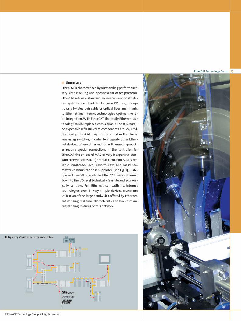
■ SummaryEtherCAT is characterized by outstanding performance,very simple wiring and openness for other protocols.EtherCAT sets new standards where conventional field-bus systems reach their limits: 1,000 I/Os in 30 μs, op-tionally twisted pair cable or optical fiber and, thanksto Ethernet and Internet technologies, optimum verti-cal integration. With EtherCAT, the costly Ethernet startopology can be replaced with a simple line structure –no expensive infrastructure components are required.Optionally, EtherCAT may also be wired in the classicway using switches, in order to integrate other Ether-net devices. Where other real-time Ethernet approach-es require special connections in the controller, forEtherCAT the on-board MAC or very inexpensive stan-dard Ethernet cards (NIC) are sufficient. EtherCAT is ver-satile: master-to-slave, slave-to-slave and master-to-master communication is supported (see Fig. 13). Safe-ty over EtherCAT is available. EtherCAT makes Ethernetdown to the I/O level technically feasible and econom-ically sensible. Full Ethernet compatibility, internettechnologies even in very simple devices, maximumutilization of the large bandwidth offered by Ethernet,outstanding real-time characteristics at low costs areoutstanding features of this network.
© EtherCAT Technology Group. All rights reserved.
18
© EtherCAT Technology Group. All rights reserved.
■ Master requirements In an embedded environment an EtherCAT Master imple-mentation has to fit some special requirements, which areoften conflicting. On one hand, a specific environment re-stricts hard- and software properties, and on the otherhand, the application requirements have to be fulfilled.
The hardware environment includes a broad variationof micro controllers (8, 16 or 32 bit) with different con-straints concerning endianness and alignment limitations,which a master needs to address. There is also a broad vari-ation of different MAC chips used where a master has toface different data access methods (DMA access, IO access,Dual Port RAM access). A special objective in an embeddedenvironment is often the lack of a hard disk drive and ofcourse the limited resources like Memory, CPU or bus band-width (when accessing the MAC). Another objective a mas-ter should meet is a broad variety of different operatingsystems or in some cases even no operating system at all.If the same master software implementation shall run onmultiple of such different systems, the main requirementsto the software are portability and footprint.
Besides these different environments a system design-er has to consider which application requirements are tofulfill. These requirements are defined by the maximumnumber of slaves to be used, what kind of slaves are usedwith respect to the required slave protocols (e.g. EoE, CoE,FoE, SoE) and how much data has to be transferred pertime period (cyclic/acyclic data volume and bus cycle rate).What also has to be considered is whether the used busconfiguration is static or dynamic. When using EtherCAT ascommunication technology between multiple embeddedsystems, there is often a special operating mode usedwhich is either the standard logical process data exchangeor a point-to-point type communication, where
The EtherCAT Technology was developed with very low cost devices in mind, like I/O terminals, sensors,and embedded controllers. EtherCAT only uses standard Ethernet frames according to IEEE 802.3.These frames are sent by the master device; the slave devices extract and/or insert data on the fly.Thus EtherCAT uses standard Ethernet MACs, where they really make sense: in the master device.And EtherCAT Slave Controllers are used, where such dedicated chips really make sense: in the slave device, where they handle the process data protocol in hardware and provide maximum real-time performance regardless of the local processing power or software quality.
■ Implementation Aspects
■ Master
slave stations are polled by acyclic commands and thecyclic part is only used to keep the system operational.
The main task for deciding which master solution touse is to clearly define how to face those conflicting re-quirements. The different options are to develop an ownmaster solution, to adapt the master sample code to theembedded environment or to purchase a commerciallyavailable master solution.
The benefit of EtherCAT in an embedded environmentis the possibility to have a scalable master by using oromitting some features or special protocols to meet theenvironment concerning memory and CPU. This is possiblebecause a master stack must not be implemented in a spe-cial hardware but can be implemented in software. Ether-CAT preserves space in your control unit because no addi-tional interface devices are needed. Furthermore it reducespower consumption because only an Ethernet MAC isneeded and no additional active I/O cards. On mass prod-ucts the cost is always a matter of desire; here EtherCATsaves money because standard MAC hardware (consumermarket) can be used, which has a very low price.
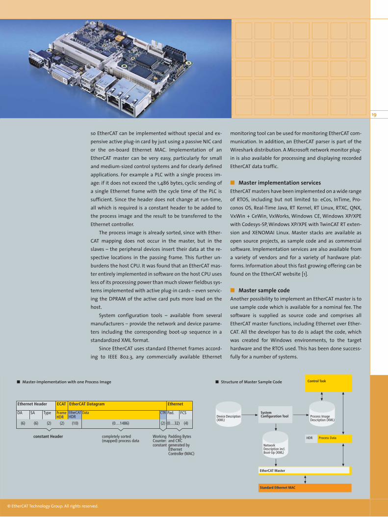
■ EtherCAT MasterEtherCAT communicates a maximum of 1,486 bytes of dis-tributed process data with just one Ethernet frame. Unlikeother solutions where the master device in each networkcycle has to process, send and receive frames for each node,EtherCAT systems typically only need one or two framesper cycle for the entire communication with all nodes.Therefore EtherCAT masters do not require a dedicatedcommunication processor. The master functionality putshardly any load on the host CPU which can handle this taskeasily besides processing the application program:
Device Description(XML)
Control Task
HDR Process Data
Process ImageDescription (XML)
SystemConfiguration Tool
NetworkDescription incl.Boot-Up (XML)
EtherCAT Master
Standard Ethernet MAC
constant Header completely sorted(mapped) process data
WorkingCounter:constant
Padding Bytesand CRCgenerated byEthernetController (MAC)
Ethernet
FrameHDRFrameHDRDA SA Type Frame
HDREtherCATHDR
Data CTR Pad. FCS
Ethernet Header ECAT EtherCAT Datagram
(6) (6) (2) (2) (10) (0…1486) (2) (0…32) (4)
■ Master-Implementation with one Process Image
19
so EtherCAT can be implemented without special and ex-pensive active plug-in card by just using a passive NIC cardor the on-board Ethernet MAC. Implementation of anEtherCAT master can be very easy, particularly for smalland medium-sized control systems and for clearly definedapplications. For example a PLC with a single process im-age: if it does not exceed the 1,486 bytes, cyclic sending ofa single Ethernet frame with the cycle time of the PLC issufficient. Since the header does not change at run-time,all which is required is a constant header to be added tothe process image and the result to be transferred to theEthernet controller.
The process image is already sorted, since with Ether-CAT mapping does not occur in the master, but in theslaves – the peripheral devices insert their data at the re-spective locations in the passing frame. This further un-burdens the host CPU. It was found that an EtherCAT mas-ter entirely implemented in software on the host CPU usesless of its processing power than much slower fieldbus sys-tems implemented with active plug-in cards – even servic-ing the DPRAM of the active card puts more load on thehost.
System configuration tools – available from severalmanufacturers – provide the network and device parame-ters including the corresponding boot-up sequence in astandardized XML format.
Since EtherCAT uses standard Ethernet frames accord-ing to IEEE 802.3, any commercially available Ethernet
© EtherCAT Technology Group. All rights reserved.
■ Structure of Master Sample Code
monitoring tool can be used for monitoring EtherCAT com-munication. In addition, an EtherCAT parser is part of theWireshark distribution. A Microsoft network monitor plug-in is also available for processing and displaying recordedEtherCAT data traffic.
■ Master implementation servicesEtherCAT masters have been implemented on a wide rangeof RTOS, including but not limited to: eCos, InTime, Pro-conos OS, Real-Time Java, RT Kernel, RT Linux, RTXC, QNX,VxWin + CeWin, VxWorks, Windows CE, Windows XP/XPEwith Codesys-SP, Windows XP/XPE with TwinCAT RT exten-sion and XENOMAI Linux. Master stacks are available asopen source projects, as sample code and as commercialsoftware. Implementation services are also available froma variety of vendors and for a variety of hardware plat-forms. Information about this fast growing offering can befound on the EtherCAT website [1].
■ Master sample codeAnother possibility to implement an EtherCAT master is touse sample code which is available for a nominal fee. Thesoftware is supplied as source code and comprises allEtherCAT master functions, including Ethernet over Ether-CAT. All the developer has to do is adapt the code, whichwas created for Windows environments, to the targethardware and the RTOS used. This has been done success-fully for a number of systems.
20
© EtherCAT Technology Group. All rights reserved.
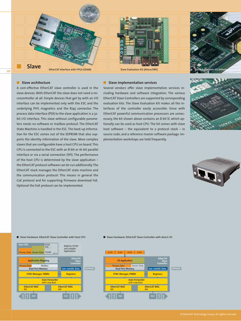
Slave Evaluation Kit (Altera/EBV)■ Slave
■ Slave Hardware: EtherCAT Slave Controller with Host CPU ■ Slave Hardware: EtherCAT Slave Controller with direct I/O
EtherCAT Interface with FPGA (IDAM) Slave Evaluation Kit (Hilscher)
■ Slave implementation servicesSeveral vendors offer slave implementation services in-cluding hardware and software integration. The variousEtherCAT Slave Controllers are supported by correspondingevaluation kits. The Slave Evaluation Kit makes all the in-terfaces of the controller easily accessible. Since withEtherCAT powerful communication processors are unnec-essary, the kit shown above contains an 8 bit ÌC which op-tionally can be used as host CPU. The kit comes with slavehost software – the equivalent to a protocol stack – insource code, and a reference master software package. Im-plementation workshops are held frequently.
■ Slave architectureA cost-effective EtherCAT slave controller is used in theslave devices. With EtherCAT the slave does not need a mi-crocontroller at all. Simple devices that get by with an I/Ointerface can be implemented only with the ESC and theunderlying PHY, magnetics and the RJ45 connector. Theprocess data interface (PDI) to the slave application is a 32-bit I/O interface. This slave without configurable parame-ters needs no software or mailbox protocol. The EtherCATState Machine is handled in the ESC. The boot-up informa-tion for the ESC comes out of the EEPROM that also sup-ports the identity information of the slave. More complexslaves that are configurable have a host CPU on board. ThisCPU is connected to the ESC with an 8-bit or 16-bit parallelinterface or via a serial connection (SPI). The performanceof the host CPU is determined by the slave application –the EtherCAT protocol software can be run additionally.TheEtherCAT stack manages the EtherCAT state machine andthe communication protocol: This means in general theCoE protocol and for supporting firmware download FoE.Optional the EoE protocol can be implemented.
EtherCAT MACMII
EEPROM
MIIEtherCAT MAC
Auto-Forwarderwith Loop Back
RegistersSYNC-Manager, FMMU
Process DataDual Port Memory
Mailbox
Host CPU
Process Data Service Data TCP/IP (optional)
HTTP,FTP, … RAM for TCP/IP
and complexApplications
Application Mapping
non volatile Data
EtherCATSlave
Controller
RJ45
Traf
o
PHY
RJ45
Traf
o
PHY
EtherCAT MACMII
EEPROM
MIIEtherCAT MAC
Auto-Forwarderwith Loop Back
RegistersSYNC-Manager, FMMU
Process DataDual Port Memory
Service Datanon volatile Data
EtherCATSlave
Controller
RJ45
Traf
o
PHY
RJ45
Traf
o
PHY
I/O Application
8 I/O8 I/O8 I/O8 I/O
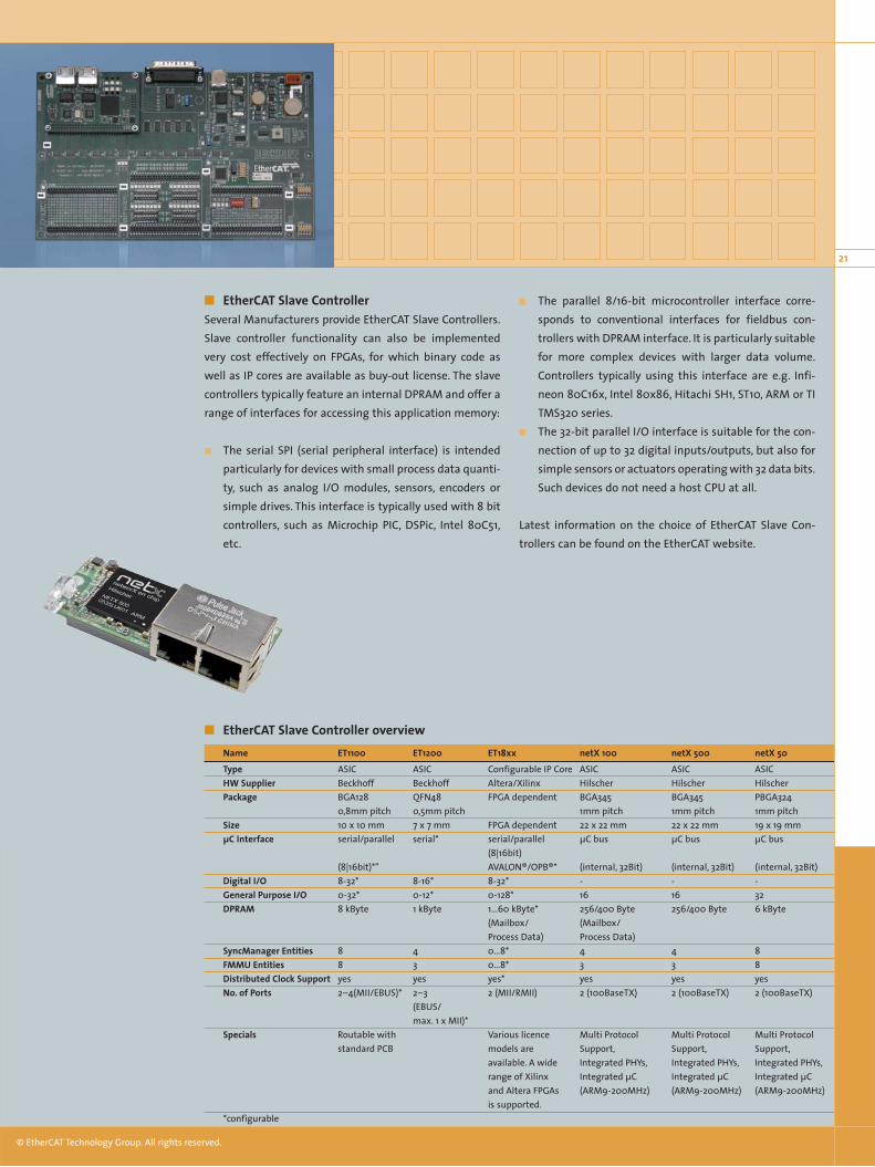
■ EtherCAT Slave Controller overviewName ET1100 ET1200 ET18xx netX 100 netX 500 netX 50Type ASIC ASIC Configurable IP Core ASIC ASIC ASICHW Supplier Beckhoff Beckhoff Altera/Xilinx Hilscher Hilscher HilscherPackage BGA128 QFN48 FPGA dependent BGA345 BGA345 PBGA324
0,8mm pitch 0,5mm pitch 1mm pitch 1mm pitch 1mm pitchSize 10 x 10 mm 7 x 7 mm FPGA dependent 22 x 22 mm 22 x 22 mm 19 x 19 mmμC Interface serial/parallel serial* serial/parallel μC bus μC bus μC bus
(8|16bit)(8|16bit)*" AVALON®/OPB®* (internal, 32Bit) (internal, 32Bit) (internal, 32Bit)
Digital I/O 8-32* 8-16* 8-32* - - -General Purpose I/O 0-32* 0-12* 0-128* 16 16 32DPRAM 8 kByte 1 kByte 1...60 kByte* 256/400 Byte 256/400 Byte 6 kByte
(Mailbox/ (Mailbox/Process Data) Process Data)
SyncManager Entities 8 4 0…8* 4 4 8FMMU Entities 8 3 0…8* 3 3 8Distributed Clock Support yes yes yes* yes yes yesNo. of Ports 2–4(MII/EBUS)* 2–3 2 (MII/RMII) 2 (100BaseTX) 2 (100BaseTX) 2 (100BaseTX)
(EBUS/max. 1 x MII)*
Specials Routable with Various licence Multi Protocol Multi Protocol Multi Protocol standard PCB models are Support, Support, Support,
available. A wide Integrated PHYs, Integrated PHYs, Integrated PHYs,range of Xilinx Integrated μC Integrated μC Integrated μCand Altera FPGAs (ARM9-200MHz) (ARM9-200MHz) (ARM9-200MHz)is supported.
*configurable
21
© EtherCAT Technology Group. All rights reserved.
Slave Evaluation Kit (Beckhoff)
■ EtherCAT Slave ControllerSeveral Manufacturers provide EtherCAT Slave Controllers.Slave controller functionality can also be implementedvery cost effectively on FPGAs, for which binary code aswell as IP cores are available as buy-out license. The slavecontrollers typically feature an internal DPRAM and offer arange of interfaces for accessing this application memory:
■ The serial SPI (serial peripheral interface) is intendedparticularly for devices with small process data quanti-ty, such as analog I/O modules, sensors, encoders orsimple drives. This interface is typically used with 8 bitcontrollers, such as Microchip PIC, DSPic, Intel 80C51,etc.
■ The parallel 8/16-bit microcontroller interface corre-sponds to conventional interfaces for fieldbus con-trollers with DPRAM interface. It is particularly suitablefor more complex devices with larger data volume.Controllers typically using this interface are e.g. Infi-neon 80C16x, Intel 80x86, Hitachi SH1, ST10, ARM or TITMS320 series.
■ The 32-bit parallel I/O interface is suitable for the con-nection of up to 32 digital inputs/outputs, but also forsimple sensors or actuators operating with 32 data bits.Such devices do not need a host CPU at all.
Latest information on the choice of EtherCAT Slave Con-trollers can be found on the EtherCAT website.
22 EtherCAT Technology Group22 EtherCAT Technology Group
© EtherCAT Technology Group. All rights reserved.
■ Why do companies chose EtherCAT?
■ Flexible TopologyThe machine structure determines the topology - not thebus system. Since no switches or hubs are needed, they donot limit the network structure. There are almost no re-strictions given by the EtherCAT technology: line, tree, star,drop lines - everything is possible.
The automatic link detection gives the possibility tosupport hot-swap functionality of machine parts. The(dis-)connection of the parts can be managed by the busmanager or can be handled automatically by the slavedevices.
With a simple extra cable to a second (standard) Ether-net port on the EtherCAT master, a very simple and cost ef-fective network redundancy is possible.
EtherCAT is also ideal for widely distributed applica-tions: Up to 100 m between two nodes on copper cables andup to 2 km on standard fiber-optic cables are supported.
Application examples:■ Baggage conveyor systems■ Bridge absorption system■ Snow blower control■ Automated warehousing■ Printing machines■ Hydraulic/electric presses■ Woodworking machines
■ High PerformanceEtherCAT is the fastest Industrial Ethernet technology withoutstanding synchronization features. It is used in all ap-plications with short cycle times like Motion Control appli-cations as well as for measurement applications withmany I/O signals.
Simply the use of EtherCAT allows one to increase thecontrol performance up to 20%, often even more. This per-formance is then available for the user application. The in-creased accuracy and productivity of the machine leads tolower costs and higher profits. EtherCAT meets today's andtomorrow's requirements!
Application examples:■ Robotics■ Machine tool applications■ CNC functionality■ Packaging machines■ Injection molding■ Engine test beds■ Measurement applications■ Ultra fast metal cutting■ Blow molding machinery■ Semiconductor + FPD manufacturing
Photo: BMW AG
23EtherCAT Technology Group 23EtherCAT Technology Group
© EtherCAT Technology Group. All rights reserved.
■ Ease of UseThe configuration and maintenance of a machine is a deci-sive factor for the life cycle costs. With EtherCAT, thesetasks are significantly simplified. The configuration andthe topology of a machine can be scanned after installa-tion and can be compared to an expected configuration.
If a device has a failure or detects errors on the com-munication systems, the outstanding diagnostic featuresgive an exact localization of the error source and thereforeallow a fast trouble shooting.
Again the performance of EtherCAT is decisive: There isno need for network "tuning", as known for standard field-bus systems. If additional information is needed from a de-vice, it can be added to the cyclic transfer (nearly) withoutlimitations by the network bandwidth.
Application examples:■ Standard PLC applications■ Automotive factory automation with short MTTR
(Mean time to repair)■ Intra-machine communication with expected hard-
ware configuration■ Modular machines■ Welding machines■ Edge banding machines
■ Low CostEtherCAT meets or even undercuts fieldbus cost levels.There is no special master card required on the master side– on-board MAC or low cost standard NIC are sufficient. Forthe slave side, highly integrated slave controllers guaran-tee low interface costs. Furthermore, between the masterand the slave standard Ethernet cables can be used. No ac-tive infrastructure components are required and thereforeno costs for buying, configuration, installation and main-tenance of these devices are necessary.
Application examples:■ Embedded systems■ Frequency inverters■ Sensors■ Mass flow controller■ Encoder■ RFID reader
24 EtherCAT Technology Group
www.ethercat.org
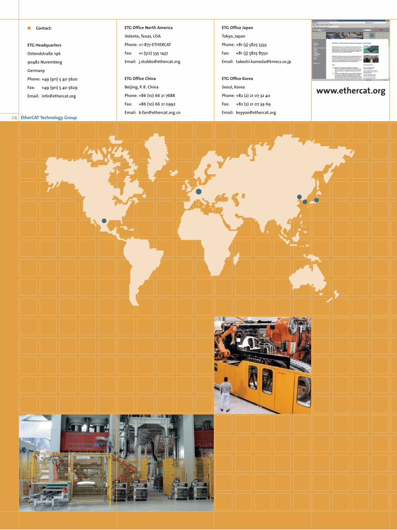
■ Contact:
ETG Headquarters
Ostendstraße 196
90482 Nuremberg
Germany
Phone: +49 (911) 5 40 5620
Fax: +49 (911) 5 40 5629
Email: [email protected]
ETG Office North America
Volente, Texas, USA
Phone: +1-877-ETHERCAT
Fax: +1 (512) 535 1437
Email: [email protected]
ETG Office China
Beijing, P. R. China
Phone: +86 (10) 66 21 7688
Fax: +86 (10) 66 21 0992
Email: [email protected]
ETG Office Japan
Tokyo, Japan
Phone: +81 (3) 5825 5333
Fax: +81 (3) 5825 8550
Email: [email protected]
ETG Office Korea
Seoul, Korea
Phone: +82 (2) 21 07 32 40
Fax: +82 (2) 21 07 39 69
Email: [email protected]